WO2012070914A2 - 무선 통신 시스템에서 제어 채널 및 데이터 채널 전송 방법 및 장치 - Google Patents
무선 통신 시스템에서 제어 채널 및 데이터 채널 전송 방법 및 장치 Download PDFInfo
- Publication number
- WO2012070914A2 WO2012070914A2 PCT/KR2011/009084 KR2011009084W WO2012070914A2 WO 2012070914 A2 WO2012070914 A2 WO 2012070914A2 KR 2011009084 W KR2011009084 W KR 2011009084W WO 2012070914 A2 WO2012070914 A2 WO 2012070914A2
- Authority
- WO
- WIPO (PCT)
- Prior art keywords
- downlink
- base station
- region
- subframe
- control
- Prior art date
Links
Images


Classifications
-
- H—ELECTRICITY
- H04—ELECTRIC COMMUNICATION TECHNIQUE
- H04L—TRANSMISSION OF DIGITAL INFORMATION, e.g. TELEGRAPHIC COMMUNICATION
- H04L27/00—Modulated-carrier systems
- H04L27/26—Systems using multi-frequency codes
- H04L27/2601—Multicarrier modulation systems
- H04L27/2602—Signal structure
-
- H—ELECTRICITY
- H04—ELECTRIC COMMUNICATION TECHNIQUE
- H04J—MULTIPLEX COMMUNICATION
- H04J11/00—Orthogonal multiplex systems, e.g. using WALSH codes
- H04J11/0023—Interference mitigation or co-ordination
- H04J11/005—Interference mitigation or co-ordination of intercell interference
- H04J11/0053—Interference mitigation or co-ordination of intercell interference using co-ordinated multipoint transmission/reception
-
- H—ELECTRICITY
- H04—ELECTRIC COMMUNICATION TECHNIQUE
- H04L—TRANSMISSION OF DIGITAL INFORMATION, e.g. TELEGRAPHIC COMMUNICATION
- H04L5/00—Arrangements affording multiple use of the transmission path
- H04L5/003—Arrangements for allocating sub-channels of the transmission path
- H04L5/0032—Distributed allocation, i.e. involving a plurality of allocating devices, each making partial allocation
- H04L5/0035—Resource allocation in a cooperative multipoint environment
-
- H—ELECTRICITY
- H04—ELECTRIC COMMUNICATION TECHNIQUE
- H04W—WIRELESS COMMUNICATION NETWORKS
- H04W72/00—Local resource management
- H04W72/20—Control channels or signalling for resource management
- H04W72/23—Control channels or signalling for resource management in the downlink direction of a wireless link, i.e. towards a terminal
-
- H—ELECTRICITY
- H04—ELECTRIC COMMUNICATION TECHNIQUE
- H04L—TRANSMISSION OF DIGITAL INFORMATION, e.g. TELEGRAPHIC COMMUNICATION
- H04L27/00—Modulated-carrier systems
- H04L27/26—Systems using multi-frequency codes
- H04L27/2601—Multicarrier modulation systems
- H04L27/2602—Signal structure
- H04L27/2603—Signal structure ensuring backward compatibility with legacy system
-
- H—ELECTRICITY
- H04—ELECTRIC COMMUNICATION TECHNIQUE
- H04W—WIRELESS COMMUNICATION NETWORKS
- H04W72/00—Local resource management
- H04W72/50—Allocation or scheduling criteria for wireless resources
- H04W72/54—Allocation or scheduling criteria for wireless resources based on quality criteria
- H04W72/541—Allocation or scheduling criteria for wireless resources based on quality criteria using the level of interference
Definitions
- the following description relates to a wireless communication system, and more particularly, to a method and apparatus for transmitting a control channel and a data channel in a wireless communication system.
- inter-cell interference may occur when a plurality of cells are arranged. Accordingly, methods for inter-cell interference coordination (ICIC) have been considered. For example, a method of restricting transmission of an interfering cell on a specific resource (on a time resource and / or a frequency resource), a method of adjusting the beam direction of the interfering cell, or the like may be applied.
- IOC inter-cell interference coordination
- interference to a neighboring cell may still occur on a resource on which transmission of an interfering cell is not limited.
- a restriction of a precoding matrix or the like may be used to adjust the beam direction of the interfering cell, which is applicable only to the data channel and not to the control channel. Due to the control channel of, interference may occur in the control channel and / or data channel of another cell.
- a control channel provided by a serving cell may collide with a control channel or a data channel from a neighboring cell. If the terminal does not receive the control channel of the serving cell correctly, the transmission and reception operations for the terminal may not be performed correctly.
- the present invention provides a method for protecting a control channel and a data channel of a specific cell from interference of another cell when a plurality of cells perform cooperative communication in order to adjust inter-cell interference.
- a method for performing downlink transmission by a base station includes a downlink control channel in a downlink subframe including a control region, a data region, and a null region. Or mapping one or more of the downlink data channels; And transmitting one or more of the downlink control channel or the downlink data channel mapped to the downlink subframe to the terminal.
- the null region may correspond to some or all of the control region of the downlink subframe of the neighboring base station, and information for determining the position of the null region may be provided to the terminal.
- a method for performing downlink reception by a terminal includes a control region, a data region, and a null region in a downlink subframe including a null region.
- the null region may correspond to part or all of the control region of the downlink subframe of the neighboring base station.
- a base station for performing downlink transmission a receiving module for receiving an uplink signal from the terminal; A transmission module for transmitting a downlink signal to the terminal; And a processor controlling the base station including the receiving module and the transmitting module.
- the processor is configured to map one or more of a downlink control channel or a downlink data channel to a downlink subframe including a control region, a data region and a null region;
- One or more of the downlink control channel or the downlink data channel mapped to the downlink subframe may be configured to be transmitted to the terminal through the transmission module.
- the null region may correspond to some or all of the control region of the downlink subframe of the neighboring base station, and information for determining the position of the null region may be provided to the terminal.
- a terminal for performing downlink reception includes a receiving module for receiving a downlink signal from a base station; A transmission module for transmitting an uplink signal to the base station; And a processor controlling the terminal including the receiving module and the transmitting module.
- the processor is configured to receive from the base station, via the receiving module, information for determining the position of the null region in a downlink subframe including a control region, a data region and a null region; Receive at least one of a downlink control channel or a downlink data channel mapped to the downlink subframe from the base station through the receiving module; And may decode at least one of the received downlink control channel or the downlink data channel.
- the null region may correspond to part or all of the control region of the downlink subframe of the neighboring base station.
- At least one of the control region or the data region of the downlink subframe of the base station may include the null region, and the null region may include one or a plurality of consecutive Orthogonal Frequency Division Multiplexing (OFDM) symbols. .
- OFDM Orthogonal Frequency Division Multiplexing
- the information for determining the position of the null region may include information about an end position of the control region and a length of the null region, information about an end position of the control region and a start position of the data region, or Information on a start position and a length of the null area may be included.
- At least one of an end position of the control region, a start position of the data region, or a length of the null region may include a physical control format indicator channel (PCFICH), a physical hybrid automatic repeat request indicator channel (PHICH), or higher layer signaling. It may be determined from the information transmitted to the terminal through.
- PCFICH physical control format indicator channel
- PHICH physical hybrid automatic repeat request indicator channel
- a control channel element (CCE) to which resource elements corresponding to the control region of the neighboring base station belong is nulled, or the PDCCH of the base station is mapped.
- the resource elements corresponding to the control region of the neighboring base station may be punctured or nulled.
- the null region may include all of the control region of the downlink subframe of the base station.
- the control information for data transmission of the downlink subframe of the base station may be transmitted through a control channel transmitted in the data area.
- control information for data transmission of the downlink subframe of the base station may be transmitted through a control channel transmitted in another downlink subframe of the base station.
- the control region may correspond to the first 1, 2 or 3 OFDM symbol intervals of the downlink subframe, and the data region may correspond to the remaining OFDM symbol interval except for the control region in the downlink subframe.
- the base station may be a base station of an interfering cell, and the neighboring base station may be a base station of an interfering cell.
- the base station may be a base station of an interfering cell, and the neighboring base station may be a base station of an interfering cell.
- Information about the positions of the control region, the data region, and the null region of the downlink subframe of each base station may be exchanged between the base station and the neighboring base station.
- a method of protecting a control channel and a data channel of one cell from interference of another cell may be provided.
- 1 is a diagram illustrating a structure of a downlink radio frame.
- FIG. 2 is a diagram illustrating a resource grid in a downlink slot.
- 3 is a diagram illustrating a structure of a downlink subframe.
- FIG. 4 is a diagram illustrating a structure of an uplink subframe.
- FIG. 5 is a configuration diagram of a wireless communication system having multiple antennas.
- FIG. 6 is a diagram illustrating a CRS and a DRS pattern defined in an existing 3GPP LTE system.
- FIG. 7 is a diagram illustrating an uplink subframe structure including an SRS symbol.
- FIG. 8 is a diagram showing an example of the implementation of the transceiver function of the FDD mode repeater.
- FIG. 9 is a diagram for describing transmission of a terminal from a repeater and downlink transmission from a base station to a repeater.
- FIG. 10 is a diagram illustrating a resource element group (REG) that is a unit to which downlink control channels are allocated.
- REG resource element group
- PCFICH physical control format indicator channel
- FIG. 12 is a diagram illustrating the positions of a PCFICH and a physical HARQ indicator channel (PHICH).
- PHICH physical HARQ indicator channel
- FIG. 13 is a diagram illustrating downlink resource element positions to which PHICH groups are mapped.
- 15 is a view for explaining an example of CoMP operation to which the present invention can be applied.
- 16 to 19 are diagrams illustrating a subframe configuration according to examples of the present invention.
- 20 is a diagram for explaining an example of a network in which inter-cell interference coordination is performed to which the present invention can be applied.
- 21 is a flowchart illustrating a method of transmitting and receiving a downlink subframe including a null area according to an embodiment of the present invention.
- FIG. 22 is a diagram showing the configuration of a preferred embodiment of a base station apparatus and a terminal apparatus according to the present invention.
- each component or feature may be considered to be optional unless otherwise stated.
- Each component or feature may be embodied in a form that is not combined with other components or features.
- some components and / or features may be combined to form an embodiment of the present invention.
- the order of the operations described in the embodiments of the present invention may be changed. Some components or features of one embodiment may be included in another embodiment or may be replaced with corresponding components or features of another embodiment.
- the base station has a meaning as a terminal node of the network that directly communicates with the terminal.
- the specific operation described as performed by the base station in this document may be performed by an upper node of the base station in some cases.
- a 'base station (BS)' may be replaced by terms such as a fixed station, a Node B, an eNode B (eNB), an access point (AP), and the like.
- the repeater may be replaced by terms such as relay node (RN) and relay station (RS).
- the term “terminal” may be replaced with terms such as a user equipment (UE), a mobile station (MS), a mobile subscriber station (MSS), a subscriber station (SS), and the like.
- Embodiments of the present invention may be supported by standard documents disclosed in at least one of the wireless access systems IEEE 802 system, 3GPP system, 3GPP LTE and LTE-Advanced (LTE-A) system and 3GPP2 system. That is, steps or parts which are not described to clearly reveal the technical spirit of the present invention among the embodiments of the present invention may be supported by the above documents. In addition, all terms disclosed in the present document can be described by the above standard document.
- CDMA code division multiple access
- FDMA frequency division multiple access
- TDMA time division multiple access
- OFDMA orthogonal frequency division multiple access
- SC-FDMA single carrier frequency division multiple access
- CDMA may be implemented with a radio technology such as Universal Terrestrial Radio Access (UTRA) or CDMA2000.
- TDMA may be implemented with wireless technologies such as Global System for Mobile communications (GSM) / General Packet Radio Service (GPRS) / Enhanced Data Rates for GSM Evolution (EDGE).
- GSM Global System for Mobile communications
- GPRS General Packet Radio Service
- EDGE Enhanced Data Rates for GSM Evolution
- OFDMA may be implemented in a wireless technology such as IEEE 802.11 (Wi-Fi), IEEE 802.16 (WiMAX), IEEE 802-20, Evolved UTRA (E-UTRA).
- UTRA is part of the Universal Mobile Telecommunications System (UMTS).
- 3rd Generation Partnership Project (3GPP) long term evolution (LTE) is part of an Evolved UMTS (E-UMTS) using E-UTRA, and employs OFDMA in downlink and SC-FDMA in uplink.
- LTE-A Advanced
- WiMAX can be described by the IEEE 802.16e standard (WirelessMAN-OFDMA Reference System) and the advanced IEEE 802.16m standard (WirelessMAN-OFDMA Advanced system). For clarity, the following description focuses on 3GPP LTE and 3GPP LTE-A systems, but the technical spirit of the present invention is not limited thereto.
- a structure of a downlink radio frame will be described with reference to FIG. 1.
- uplink / downlink data packet transmission is performed in units of subframes, and one subframe is defined as a predetermined time interval including a plurality of OFDM symbols.
- the 3GPP LTE standard supports a type 1 radio frame structure applicable to frequency division duplex (FDD) and a type 2 radio frame structure applicable to time division duplex (TDD).
- the downlink radio frame consists of 10 subframes, and one subframe consists of two slots in the time domain.
- the time it takes for one subframe to be transmitted is called a transmission time interval (TTI).
- TTI transmission time interval
- one subframe may have a length of 1 ms and one slot may have a length of 0.5 ms.
- One slot includes a plurality of OFDM symbols in the time domain and a plurality of resource blocks (RBs) in the frequency domain.
- RBs resource blocks
- a resource block (RB) is a resource allocation unit and may include a plurality of consecutive subcarriers in one slot.
- the number of OFDM symbols included in one slot may vary depending on the configuration of a cyclic prefix (CP).
- CP has an extended CP (normal CP) and a normal CP (normal CP).
- normal CP normal CP
- the number of OFDM symbols included in one slot may be seven.
- the OFDM symbol is configured by an extended CP, since the length of one OFDM symbol is increased, the number of OFDM symbols included in one slot is smaller than that of the normal CP.
- the number of OFDM symbols included in one slot may be six. If the channel state is unstable, such as when the terminal moves at a high speed, an extended CP may be used to further reduce intersymbol interference.
- one subframe includes 14 OFDM symbols.
- the first two or three OFDM symbols of each subframe may be allocated to a physical downlink control channel (PDCCH), and the remaining OFDM symbols may be allocated to a physical downlink shared channel (PDSCH).
- PDCCH physical downlink control channel
- PDSCH physical downlink shared channel
- Type 2 radio frames consist of two half frames, each of which has five subframes, a downlink pilot time slot (DwPTS), a guard period (GP), and an uplink pilot time slot (UpPTS).
- DwPTS downlink pilot time slot
- GP guard period
- UpPTS uplink pilot time slot
- One subframe consists of two slots.
- DwPTS is used for initial cell search, synchronization or channel estimation at the terminal.
- UpPTS is used for channel estimation at the base station and synchronization of uplink transmission of the terminal.
- the guard period is a period for removing interference generated in the uplink due to the multipath delay of the downlink signal between the uplink and the downlink.
- one subframe consists of two slots regardless of the radio frame type.
- the structure of the radio frame is only an example, and the number of subframes included in the radio frame or the number of slots included in the subframe and the number of symbols included in the slot may be variously changed.
- FIG. 2 is a diagram illustrating a resource grid in a downlink slot.
- One downlink slot includes seven OFDM symbols in the time domain and one resource block (RB) is shown to include 12 subcarriers in the frequency domain, but the present invention is not limited thereto.
- one slot includes 7 OFDM symbols in the case of a general cyclic prefix (CP), but one slot may include 6 OFDM symbols in the case of an extended-CP (CP).
- Each element on the resource grid is called a resource element.
- One resource block includes 12 ⁇ 7 resource elements.
- the number of N DLs of resource blocks included in the downlink slot depends on the downlink transmission bandwidth.
- the structure of the uplink slot may be the same as the structure of the downlink slot.
- FIG. 3 is a diagram illustrating a structure of a downlink subframe.
- Up to three OFDM symbols at the front of the first slot in one subframe correspond to a control region to which a control channel is allocated.
- the remaining OFDM symbols correspond to data regions to which a physical downlink shared channel (PDSCH) is allocated.
- Downlink control channels used in the 3GPP LTE system include, for example, a Physical Control Format Indicator Channel (PCFICH), a Physical Downlink Control Channel (PDCCH), and a Physical HARQ Indicator Channel.
- PCFICH Physical Hybrid automatic repeat request Indicator Channel
- the PCFICH is transmitted in the first OFDM symbol of a subframe and includes information on the number of OFDM symbols used for control channel transmission in the subframe.
- the PHICH includes a HARQ ACK / NACK signal as a response of uplink transmission.
- Control information transmitted through the PDCCH is referred to as downlink control information (DCI).
- DCI includes uplink or downlink scheduling information or an uplink transmit power control command for a certain terminal group.
- the PDCCH is a resource allocation and transmission format of the downlink shared channel (DL-SCH), resource allocation information of the uplink shared channel (UL-SCH), paging information of the paging channel (PCH), system information on the DL-SCH, on the PDSCH Resource allocation of upper layer control messages such as random access responses transmitted to the network, a set of transmit power control commands for individual terminals in an arbitrary terminal group, transmission power control information, and activation of voice over IP (VoIP) And the like.
- a plurality of PDCCHs may be transmitted in the control region.
- the UE may monitor the plurality of PDCCHs.
- the PDCCH is transmitted in an aggregation of one or more consecutive Control Channel Elements (CCEs).
- CCEs Control Channel Elements
- the CCE is a logical allocation unit used to provide a PDCCH at a coding rate based on the state of a radio channel.
- the CCE corresponds to a plurality of resource element groups (REGs).
- the format of the PDCCH and the number of available bits are determined according to the correlation between the number of CCEs and the coding rate provided by the CCEs.
- the number of CCEs used for PDCCH transmission is called a CCE aggregation level.
- the CCE combination level is a CCE unit for searching for a PDCCH.
- the size of the CCE combination level is defined by the number of adjacent CCEs. For example, the CCE combination level can be 1, 2, 4 or 8.
- the base station determines the PDCCH format according to the DCI transmitted to the terminal, and adds a cyclic redundancy check (CRC) to the control information.
- CRC cyclic redundancy check
- the CRC is masked with an identifier called a Radio Network Temporary Identifier (RNTI) according to the owner or purpose of the PDCCH.
- RNTI Radio Network Temporary Identifier
- the PDCCH is for a specific terminal, the cell-RNTI (C-RNTI) identifier of the terminal may be masked to the CRC.
- a paging indicator identifier P-RNTI
- SI-RNTI system information identifier and system information RNTI
- RA-RNTI Random Access-RNTI
- the uplink subframe may be divided into a control region and a data region in the frequency domain.
- a physical uplink control channel (PUCCH) including uplink control information is allocated to the control region.
- a physical uplink shared channel (PUSCH) including user data is allocated.
- PUCCH physical uplink control channel
- PUSCH physical uplink shared channel
- one UE does not simultaneously transmit a PUCCH and a PUSCH.
- PUCCH for one UE is allocated to an RB pair in a subframe. Resource blocks belonging to a resource block pair occupy different subcarriers for two slots. This is called a resource block pair allocated to the PUCCH is frequency-hopped at the slot boundary.
- FIG. 5 is a configuration diagram of a wireless communication system having multiple antennas.
- the theoretical ratio is proportional to the number of antennas, unlike when the transmitter or the receiver uses multiple antennas only.
- Channel transmission capacity is increased. Therefore, the transmission rate can be improved and the frequency efficiency can be significantly improved.
- the transmission rate can theoretically increase as the rate of increase rate R i multiplied by the maximum transmission rate R o when using a single antenna.
- a transmission rate four times higher than a single antenna system may be theoretically obtained. Since the theoretical capacity increase of multi-antenna systems was proved in the mid 90's, various techniques to actively lead to the actual data rate improvement have been actively studied. In addition, some technologies are already being reflected in various wireless communication standards such as 3G mobile communication and next generation WLAN.
- the research trends related to multi-antennas to date include the study of information theory aspects related to the calculation of multi-antenna communication capacity in various channel environments and multi-access environments, the study of wireless channel measurement and model derivation of multi-antenna systems, improvement of transmission reliability, and improvement of transmission rate. Research is being actively conducted from various viewpoints, such as research on space-time signal processing technology.
- the transmission signal when there are N T transmit antennas, the maximum information that can be transmitted is N T.
- the transmission information may be expressed as follows.
- Each transmission information The transmit power may be different.
- Each transmit power In this case, the transmission information whose transmission power is adjusted may be expressed as follows.
- Weighting matrix N T transmitted signals actually applied by applying Consider the case where is configured.
- Weighting matrix Plays a role in properly distributing transmission information to each antenna according to a transmission channel situation.
- Vector It can be expressed as follows.
- Received signal is received signal of each antenna when there are N R receiving antennas Can be expressed as a vector as
- channels may be divided according to transmit / receive antenna indexes. From the transmit antenna j to the channel through the receive antenna i It is indicated by. Note that in the order of the index, the receiving antenna index is first, and the index of the transmitting antenna is later.
- FIG. 5B is a diagram illustrating a channel from N T transmit antennas to receive antenna i .
- the channels may be bundled and displayed in vector and matrix form.
- a channel arriving from the total N T transmit antennas to the receive antenna i may be represented as follows.
- AWGN Additive White Gaussian Noise
- the received signal may be expressed as follows through the above-described mathematical modeling.
- the channel matrix indicating the channel state The number of rows and columns of is determined by the number of transmit and receive antennas.
- Channel matrix The number of rows is equal to the number of receive antennas N R
- the number of columns is equal to the number of transmit antennas N T. That is, the channel matrix The matrix is N R ⁇ N T.
- the rank of a matrix is defined as the minimum number of rows or columns that are independent of each other. Thus, the rank of the matrix cannot be greater than the number of rows or columns.
- Channel matrix Rank of ( ) Is limited to
- rank may be defined as the number of nonzero eigenvalues when the matrix is eigenvalue decomposition.
- another definition of rank may be defined as the number of nonzero singular values when singular value decomposition is performed. Therefore, the physical meaning of rank in the channel matrix is the maximum number that can send different information in a given channel.
- the transmitted packet is transmitted through a wireless channel
- signal distortion may occur during the transmission process.
- the distortion In order to correctly receive the distorted signal at the receiving end, the distortion must be corrected in the received signal using the channel information.
- a method of transmitting the signal known to both the transmitting side and the receiving side and finding the channel information with the distortion degree when the signal is received through the channel is mainly used.
- the signal is called a pilot signal or a reference signal.
- the downlink reference signal includes a common reference signal (CRS) shared by all terminals in a cell and a dedicated reference signal (DRS) only for a specific terminal.
- CRS common reference signal
- DRS dedicated reference signal
- the receiver estimates the state of the channel from the CRS and feeds back indicators related to channel quality such as channel quality indicator (CQI), precoding matrix index (PMI), and / or rank indicator (RI) to the transmitter (base station). can do.
- CQI channel quality indicator
- PMI precoding matrix index
- RI rank indicator
- the CRS may be called a cell-specific reference signal.
- RS related to feedback of Channel State Information (CSI) such as CQI / PMI / RI may be separately defined as CSI-RS.
- CSI-RS Channel State Information
- the DRS may be transmitted through the corresponding RE.
- the UE may be instructed as to whether DRS is present from a higher layer and may be instructed that the DRS is valid only when the corresponding PDSCH is mapped.
- the DRS may also be called a UE-specific reference signal or a demodulation reference signal (DMRS).
- FIG. 6 is a diagram illustrating a pattern in which CRSs and DRSs defined in an existing 3GPP LTE system (eg, Release-8) are mapped onto a downlink resource block pair (RB pair).
- a downlink resource block pair as a unit to which a reference signal is mapped may be expressed in units of 12 subcarriers in one subframe ⁇ frequency in time. That is, one resource block pair has 14 OFDM symbol lengths in the case of a general CP (Fig. 6 (a)) and 12 OFDM symbol lengths in the case of an extended CP (Fig. 6 (b)).
- FIG. 6 shows a position of a reference signal on a resource block pair in a system in which a base station supports four transmit antennas.
- resource elements RE denoted by '0', '1', '2' and '3' indicate positions of CRSs for antenna port indexes 0, 1, 2, and 3, respectively.
- the resource element denoted as 'D' in FIG. 6 indicates the position of the DRS.
- the CRS is used to estimate a channel of a physical antenna terminal, and is a reference signal that can be commonly received by all UEs in a cell, and is distributed over all bands.
- CRS may be used for channel state information (CSI) acquisition and data demodulation purposes.
- CSI channel state information
- the CRS is defined in various forms according to the antenna configuration of the transmitting side (base station).
- the 3GPP LTE (eg, Release-8) system supports various antenna configurations, and the downlink signal transmitter (base station) uses three types of antenna configurations such as a single antenna, two transmit antennas, and four transmit antennas.
- a reference signal for a single antenna port is arranged.
- reference signals for two antenna ports are arranged in a time division multiplexing and / or frequency division multiplexing scheme. That is, reference signals for the two antenna ports may be arranged in different time resources and / or different frequency resources to be distinguished from each other.
- Channel information estimated by the downlink signal receiving side (terminal) through the CRS is a single antenna transmission (Transmission diversity), closed-loop spatial multiplexing, open-loop It may be used for demodulation of data transmitted by a transmission scheme such as open-loop spatial multiplexing, multi-user MIMO, or the like.
- the reference signal when transmitting a reference signal from one antenna port, the reference signal is transmitted to a resource element (RE) position designated according to the reference signal pattern, and a signal is transmitted to a resource element (RE) position designated for another antenna port. Do not send.
- Equation 12 k is a subcarrier index, l is a symbol index, and p is an antenna port index.
- the position of the reference signal in the frequency domain depends on the V shift value. Since the V shift value also depends on the cell ID, the position of the reference signal has a different frequency shift value for each cell.
- the position on the frequency domain of the CRS may be shifted for each cell to be different.
- a reference signal is located every 3 subcarriers
- one cell may be arranged on a 3k subcarrier and another cell on a 3k + 1 subcarrier.
- the reference signal is arranged at 6 RE intervals (ie, 6 subcarrier intervals) in the frequency domain, and maintains 3 RE intervals in the frequency domain from the RE where reference signals for other antenna ports are arranged.
- power boosting may be applied to the CRS.
- Power boosting refers to the transmission of a reference signal with higher power by taking power from another RE other than the RE allocated for the reference signal among the resource elements RE of one OFDM symbol.
- reference signal positions are arranged at regular intervals starting from the symbol index ( l ) 0 of each slot.
- the time interval is defined differently depending on the CP length.
- the general CP case is located at symbol indexes 0 and 4 of the slot
- the extended CP case is located at symbol indexes 0 and 3 of the slot.
- Only one reference signal is defined for up to two antenna ports in one OFDM symbol. Therefore, when transmitting 4 transmit antennas, the reference signals for antenna ports 0 and 1 are located at symbol indexes 0 and 4 of slots (symbol indexes 0 and 3 in the case of an extended CP), and the reference signals for antenna ports 2 and 3 It is located at symbol index 1 of the slot.
- the frequency positions of the reference signals for the antenna ports 2 and 3 are switched with each other in the second slot.
- a system with an extended antenna configuration (eg, an LTE-A system) can be designed.
- the extended antenna configuration can be, for example, eight transmit antenna configurations.
- it is necessary to support terminals operating in the existing antenna configuration, that is, backward compatibility.
- adding a CRS for a new antenna port to a system having an existing antenna configuration has a disadvantage in that the reference signal overhead is rapidly increased to decrease the data rate.
- CSI-RS channel state information
- the DRS (or terminal-specific reference signal) is a reference signal used for data demodulation.
- the terminal receives the reference signal by using the precoding weight used for the specific terminal as the reference signal when transmitting multiple antennas, Equivalent channel combined with the precoding weight transmitted in the transmission antenna and the transmission channel can be estimated.
- Equation 13 is for the case of a general CP
- Equation 14 is for the case of an extended CP.
- Equations 13 and 14 k is a subcarrier index, l is a symbol index, and p is an antenna port index.
- the position of the reference signal in the frequency domain depends on the V shift value. Since the V shift value also depends on the cell ID, the position of the reference signal has a different frequency shift value for each cell.
- LTE-A Advanced
- 3GPP LTE 3GPP LTE
- 3GPP LTE 3GPP LTE
- two or more layers may be used to support data transmission through an added antenna.
- DRS can be defined.
- CoMP Cooperative Multi-Point
- CoMP transmission and reception techniques also referred to as co-MIMO, collaborative MIMO, network MIMO, etc.
- CoMP technology can increase the performance of the terminal located in the cell-edge (cell-edge) and increase the average sector throughput (throughput).
- inter-cell interference may reduce performance and average sector yield of a terminal located in a cell boundary.
- ICI inter-cell interference
- existing LTE system is located in a cell-boundary in an environment that is limited by interference by using a simple passive technique such as fractional frequency reuse (FFR) through UE-specific power control.
- FFR fractional frequency reuse
- the method for the terminal to have a proper yield performance has been applied.
- CoMP transmission scheme may be applied.
- CoMP schemes applicable to downlink can be classified into joint processing (JP) techniques and coordinated scheduling / beamforming (CS / CB) techniques.
- JP joint processing
- CS / CB coordinated scheduling / beamforming
- the JP technique may use data at each point (base station) of the CoMP cooperative unit.
- CoMP cooperative unit means a set of base stations used in a cooperative transmission scheme.
- the JP technique can be classified into a joint transmission technique and a dynamic cell selection technique.
- the joint transmission technique refers to a technique in which a PDSCH is transmitted from a plurality of points (part or all of CoMP cooperative units) at a time. That is, data transmitted to a single terminal may be simultaneously transmitted from a plurality of transmission points. According to the joint transmission technique, the quality of a received signal may be improved coherently or non-coherently, and may also actively cancel interference with other terminals.
- Dynamic cell selection scheme refers to a scheme in which PDSCH is transmitted from one point (of CoMP cooperative units) at a time. That is, data transmitted to a single terminal at a specific time point is transmitted from one point, and other points in the cooperative unit do not transmit data to the corresponding terminal at that time point, and a point for transmitting data to the corresponding terminal is dynamically selected. Can be.
- CoMP cooperative units may cooperatively perform beamforming of data transmission for a single terminal.
- data is transmitted only in the serving cell, but user scheduling / beamforming may be determined by coordination of cells of a corresponding CoMP cooperative unit.
- coordinated multi-point reception means receiving a signal transmitted by coordination of a plurality of geographically separated points.
- CoMP schemes applicable to uplink may be classified into joint reception (JR) and coordinated scheduling / beamforming (CS / CB).
- the JR scheme means that a signal transmitted through a PUSCH is received at a plurality of reception points.
- a PUSCH is received only at one point, but user scheduling / beamforming is determined by coordination of cells of a CoMP cooperative unit. It means to be.
- SRS Sounding Reference Signal
- the sounding reference signal is mainly used for frequency-selective scheduling on uplink by a base station measuring channel quality and is not associated with uplink data and / or control information transmission. Do not.
- the present invention is not limited thereto, and the SRS may be used for the purpose of improved power control or for supporting various start-up functions of terminals not recently scheduled.
- the start function is, for example, an initial modulation and coding scheme (MCS), initial power control for data transmission, timing advance and frequency anti-selective scheduling (in the first slot of the subframe).
- MCS modulation and coding scheme
- Frequency resources are selectively allocated and may include pseudo-random hopping to other frequencies in the second slot).
- the SRS may be used for downlink channel quality measurement under the assumption that the radio channel is reciprocal between uplink and downlink. This assumption is particularly valid in time division duplex (TDD) systems where uplink and downlink share the same frequency band and are distinguished in the time domain.
- TDD time division duplex
- the subframe in which the SRS is transmitted by any terminal in the cell is indicated by cell-specific broadcast signaling.
- the 4-bit cell-specific 'SrsSubframeConfiguration' parameter represents fifteen possible configurations of subframes in which an SRS can be transmitted within each radio frame. This configuration can provide flexibility to adjust SRS overhead according to network deployment scenarios.
- the configuration of the other (16th) of the parameter is to switch off the SRS transmission in the cell completely, for example, may be suitable for a cell serving mainly high speed terminals.
- the SRS is always transmitted on the last SC-FDMA symbol of the configured subframe. Therefore, the SRS and the demodulation reference signal (DMRS) are located on different SC-FDMA symbols. PUSCH data transmissions are not allowed on the SC-FDMA symbols designated for SRS transmissions, and therefore do not exceed approximately 7% even when the sounding overhead is highest (that is, when there is an SRS transmission symbol in every subframe). .
- Each SRS symbol is generated by a base sequence (random sequence or Zadoff-Chu-based sequence set) for a given time unit and frequency band, and all terminals in a cell use the same base sequence.
- SRS transmissions from a plurality of terminals in a cell in the same time unit and the same frequency band are orthogonally distinguished by different cyclic shifts of a basic sequence allocated to the plurality of terminals.
- SRS sequences of different cells can be distinguished by assigning different base sequences from cell to cell, but orthogonality between different base sequences is not guaranteed.
- Repeaters may be considered, for example, to extend high data rate coverage, improve group mobility, ad hoc network deployment, improve cell boundary yield and / or provide network coverage in new areas.
- the relay plays a role of forwarding transmission and reception between the base station and the terminal, and two types of links (backhaul link and access link) having different attributes are applied to each carrier frequency band.
- the base station may comprise a donor cell.
- the repeater is wirelessly connected to the radio-access network through the donor cell.
- the backhaul link between the base station and the repeater may be represented as a backhaul downlink when using a downlink frequency band or a downlink subframe resource, and as a backhaul uplink when using an uplink frequency band or an uplink subframe resource.
- the frequency band is a resource allocated in the frequency division duplex (FDD) mode
- the subframe is a resource allocated in the time division duplex (TDD) mode.
- FDD frequency division duplex
- TDD time division duplex
- the access link between the repeater and the terminal (s) uses downlink frequency band or downlink subframe resources, it is expressed as access downlink, and when uplink frequency band or uplink subframe resource is used, access uplink. Can be represented by a link.
- the base station requires a function of uplink reception and downlink transmission
- the terminal requires a function of uplink transmission and downlink reception.
- the repeater requires all the functions of backhaul uplink transmission to the base station, access uplink reception from the terminal, backhaul downlink reception from the base station, and access downlink transmission to the terminal.
- the receiving function of the repeater is as follows.
- the downlink received signal from the base station is passed to the fast fourier transform (FFT) module 912 via the duplexer 911 and the OFDMA baseband reception process 913 is performed.
- the uplink received signal from the terminal is delivered to the FFT module 922 via the duplexer 921 and a Discrete Fourier Transform-spread-OFDMA (DFT-s-OFDMA) baseband reception process 923 is performed.
- DFT-s-OFDMA Discrete Fourier Transform-spread-OFDMA
- the downlink signal receiving process from the base station and the uplink signal receiving process from the terminal may be performed in parallel at the same time. Meanwhile, the transmission function of the repeater will be described conceptually as follows.
- the uplink transmission signal to the base station is transmitted via a DFT-s-OFDMA baseband transmission process 933, an Inverse FFT (IFFT) module 932, and a duplexer 931.
- the downlink transmission signal to the terminal is transmitted through the OFDM baseband transmission process 943, the IFFT module 942 and the duplexer 941.
- the uplink signal transmission process to the base station and the downlink signal transmission process to the terminal may be performed in parallel at the same time.
- the duplexers shown in one direction may be implemented by one bidirectional duplexer.
- the duplexer 911 and the duplexer 931 may be implemented as one bidirectional duplexer
- the duplexer 921 and the duplexer 941 may be implemented as one bidirectional duplexer.
- the IFFT module and baseband process module lines associated with transmission and reception on a particular carrier frequency band in one bidirectional duplexer may be implemented as branching.
- the case in which the backhaul link operates in the same frequency band as the access link is called 'in-band', and the frequency band in which the backhaul link and the access link are different.
- the case of operating at is called 'out-band'.
- a terminal operating according to an existing LTE system eg, Release-8 (hereinafter referred to as a legacy terminal) should be able to access the donor cell.
- the repeater may be classified as a transparent repeater or a non-transparent repeater.
- a transparent means a case in which a terminal does not recognize whether it communicates with a network through a repeater
- a non-transient refers to a case in which a terminal recognizes whether a terminal communicates with a network through a repeater.
- the repeater may be divided into a repeater configured as part of the donor cell or a repeater controlling the cell by itself.
- the repeater configured as part of the donor cell may have a repeater identifier (ID), but does not have the repeater's own cell identity.
- ID a repeater identifier
- RRM Radio Resource Management
- a relay configured as part of the donor cell.
- such a repeater can support legacy terminals.
- various types of smart repeaters, decode-and-forward relays, L2 (second layer) repeaters, and type-2 repeaters are examples of such repeaters.
- the repeater controls one or several cells, each of the cells controlled by the repeater is provided with a unique physical layer cell identity, and may use the same RRM mechanism. From a terminal perspective, there is no difference between accessing a cell controlled by a repeater and accessing a cell controlled by a general base station.
- the cell controlled by this repeater may support the legacy terminal.
- self-backhauling repeaters, L3 (third layer) repeaters, type-1 repeaters and type-1a repeaters are such repeaters.
- the type-1 repeater controls the plurality of cells as an in-band repeater, each of which appears to be a separate cell from the donor cell from the terminal's point of view. Also, the plurality of cells have their own physical cell IDs (defined in LTE Release-8), and the repeater may transmit its own synchronization channel, reference signal, and the like. In the case of single-cell operation, the terminal may receive scheduling information and HARQ feedback directly from the relay and transmit its control channel (scheduling request (SR), CQI, ACK / NACK, etc.) to the relay.
- the type-1 repeater appears to be a legacy base station (base stations operating according to the LTE Release-8 system). That is, it has backward compatibility.
- the type-1 repeater may be seen as a base station different from the legacy base station, thereby providing performance improvement.
- the type-1a repeater has the same features as the type-1 repeater described above in addition to operating out-band.
- the operation of the type-1a repeater may be configured to minimize or eliminate the impact on L1 (first layer) operation.
- the type-2 repeater is an in-band repeater and does not have a separate physical cell ID and thus does not form a new cell.
- the type 2 repeater is transparent to the legacy terminal, and the legacy terminal is not aware of the presence of the type 2 repeater.
- the type-2 repeater may transmit a PDSCH, but not at least CRS and PDCCH.
- resource partitioning In order for the repeater to operate in-band, some resources in time-frequency space must be reserved for the backhaul link and these resources can be configured not to be used for the access link. This is called resource partitioning.
- the backhaul downlink and the access downlink may be multiplexed in a time division multiplexing (TDM) scheme on one carrier frequency (ie, only one of the backhaul downlink or the access downlink is activated at a specific time).
- TDM time division multiplexing
- the backhaul uplink and access uplink may be multiplexed in a TDM manner on one carrier frequency (ie, only one of the backhaul uplink or access uplink is activated at a particular time).
- Backhaul link multiplexing in FDD may be described as backhaul downlink transmission is performed in a downlink frequency band, and backhaul uplink transmission is performed in an uplink frequency band.
- Backhaul link multiplexing in TDD may be described as backhaul downlink transmission is performed in a downlink subframe of a base station and a repeater, and backhaul uplink transmission is performed in an uplink subframe of a base station and a repeater.
- an in-band repeater for example, when a backhaul downlink reception from a base station and an access downlink transmission to a terminal are simultaneously performed in a predetermined frequency band, a signal transmitted from the transmitting end of the repeater is received at the receiving end of the repeater. This may result in signal interference or RF jamming at the RF front-end of the repeater. Similarly, if the reception of the access uplink from the terminal and the transmission of the backhaul uplink to the base station are simultaneously performed in a predetermined frequency band, signal interference may occur at the RF front end of the repeater.
- simultaneous transmission and reception in one frequency band in a repeater is sufficient separation between the received signal and the transmitted signal (e.g., with sufficient geographical separation of the transmit and receive antennas (e.g., ground / underground)). If is not provided, it is difficult to implement.
- a first subframe 1010 is a general subframe and a downlink (ie, access downlink) control signal and data are transmitted from a repeater to a terminal
- the second subframe 1020 is a multicast broadcast single frequency (MBSFN).
- a control signal is transmitted from the repeater to the terminal in the control region 1021 of the downlink subframe, but no transmission is performed from the repeater to the terminal in the remaining region 1022 of the downlink subframe.
- the legacy UE since the physical downlink control channel (PDCCH) is expected to be transmitted in all downlink subframes (in other words, the repeater receives the PDCCH in every subframe and the legacy UEs in their area measure the measurement function). It is necessary to support to perform the (), to transmit the PDCCH in all downlink subframes for the correct operation of the legacy terminal.
- PDCCH physical downlink control channel
- the repeater needs to perform access downlink transmission instead of receiving the backhaul downlink.
- the PDCCH is transmitted from the repeater to the terminal in the control region 1021 of the second subframe, backward compatibility with respect to the legacy terminal served by the repeater may be provided.
- the repeater may receive the transmission from the base station while no transmission is performed from the repeater to the terminal. Accordingly, through this resource partitioning scheme, it is possible to prevent access downlink transmission and backhaul downlink reception from being simultaneously performed in the in-band repeater.
- MBSFN subframe is a subframe for MBMS (Multimedia Broadcast and Multicast Service) in principle, and MBMS means a service for transmitting the same signal simultaneously in multiple cells.
- the control region 1021 of the second subframe may be referred to as a relay non-hearing section.
- the repeater non-listening period means a period in which the repeater transmits the access downlink signal without receiving the backhaul downlink signal. This interval may be set to 1, 2 or 3 OFDM lengths as described above.
- the repeater may perform access downlink transmission to the terminal and receive the backhaul downlink from the base station in the remaining area 1022.
- the guard time GT needs to be set so that the repeater performs transmission / reception mode switching in the first partial section of the backhaul downlink reception region 1022.
- a guard time GT for the reception / transmission mode switching of the repeater may be set.
- the length of this guard time may be given as a value in the time domain, for example, may be given as k (k ⁇ 1) time sample (Ts) values, or may be set to one or more OFDM symbol lengths. have.
- the guard time of the last part of the subframe may not be defined or set.
- Such guard time may be defined only in a frequency domain configured for backhaul downlink subframe transmission in order to maintain backward compatibility (when a guard time is set in an access downlink period, legacy terminals cannot be supported).
- the repeater may receive the PDCCH and the PDSCH from the base station. This may be expressed as a relay-PDCCH (R-PDCCH) and an R-PDSCH (Relay-PDSCH) in the sense of a relay dedicated physical channel.
- the first three OFDM symbols of each subframe may be used as an area for transmitting the downlink control channel, and one to three OFDM symbols may be used according to the overhead of the downlink control channel.
- PCFICH may be used to adjust the number of OFDM symbols for the downlink control channel for each subframe.
- the PHICH may be used to provide an acknowledgment (acknowledgment (ACK) / negative acknowledgment (NACK)) for the uplink transmission through the downlink.
- ACK acknowledgeledgment
- NACK negative acknowledgment
- PDCCH may be used for transmission of control information for downlink data transmission or uplink data transmission.
- FIG. 10 shows that the downlink control channels as described above are allocated in a resource element group (REG) unit in the control region of each subframe.
- FIG. 10A illustrates a system having one or two transmit antenna configurations
- FIG. 10B illustrates a system having four transmit antenna configurations.
- the REG which is a basic resource unit to which a control channel is allocated, is composed of four REs concatenated in the frequency domain except for a resource element to which a reference signal is allocated.
- a certain number of REGs may be used for transmission of the downlink control channel.
- PCFICH Physical Control Format Indicator Channel
- PDCCH may be transmitted between OFDM symbol indexes 0 and 2 in order to provide resource allocation information of the corresponding subframe in each subframe, and OFDM symbol index 0 is used according to overhead of the control channel, or OFDM symbol Index 0 and 1 may be used, or OFDM symbol indexes 0 to 2 may be used.
- OFDM symbol Index 0 and 1 may be used, or OFDM symbol indexes 0 to 2 may be used.
- the number of OFDM symbols used by the control channel may be changed for each subframe, and information on this may be provided through the PCFICH. Therefore, the PCFICH must be transmitted in each subframe.
- CFI Control Format Indicator
- FIG. 11 is a diagram illustrating a method of transmitting a PCFICH.
- the REG shown in FIG. 11 is composed of four subcarriers, is composed only of data subcarriers except RS (reference signal), and in general, a transmit diversity scheme may be applied.
- the location of the REG can also be frequency shifted from cell to cell (ie, depending on the cell identifier) so as not to interfere between cells.
- the PCFICH is always transmitted in the first OFDM symbol (OFDM symbol index 0) of the subframe. Accordingly, when receiving the subframe, the receiving end first checks the information of the PCFICH to determine the number of OFDM symbols to which the PDCCH is transmitted, and accordingly, may receive control information transmitted through the PDCCH.
- PHICH Physical Hybrid-ARQ Indicator Channel
- FIG. 12 is a diagram illustrating positions of PCFICH and PHICH channels generally applied in a specific bandwidth.
- ACK / NACK information for uplink data transmission is transmitted through the PHICH.
- Several PHICH groups are created in one subframe, and several PHICHs exist in one PHICH group. Therefore, one PHICH group includes PHICH channels for several terminals.
- PHICH allocation for each terminal in a plurality of PHICH groups includes a lowest PRB index of a PUSCH resource allocation and an upward PRB index.
- a cyclic shift index for a demodulation reference signal (DMRS) transmitted through a link grant PDCCH is used.
- the DMRS is an uplink reference signal and is a signal provided together with uplink transmission for channel estimation for demodulation of uplink data.
- PHICH resources It is known through an index pair such as Means PHICH group number, Denotes an orthogonal sequence index in the PHICH group.
- the number of PHICH groups may be set by a higher layer, and the number of PHICH groups may be derived from information on the amount of PHICH resources transmitted through a physical broadcast channel (PBCH).
- PBCH physical broadcast channel
- FIG. 13 is a diagram illustrating downlink resource element positions to which PHICH groups are mapped.
- the PHICH group may be configured in different time domains (ie, different OFDM symbols) in one subframe as shown in FIG. 13 according to the PHICH duration.
- the PHICH interval is 1, the PHICH is transmitted in OS0 (OFDM symbol index 0).
- the PHICH interval is 2, the PHICH is transmitted in OS1 and OS2 (OFDM symbol index 0 and 1).
- 3 indicates that PHICH is transmitted in OS0 to 2 (OFDM symbol index 0 to 2).
- inter-cell interference coordination is performed such as restricting transmission of a specific cell to specific resources or adjusting beam direction of a specific cell.
- heterogeneous network refers to a network where a macro base station (Macro eNB) and a micro base station (Micro eNB) coexist, even when using the same Radio Access Technology (RAT).
- Macro base station is a general base station of a wireless communication system having a wide coverage and high transmit power.
- the macro base station may be referred to as a macro cell.
- the micro base station may be referred to as a micro cell, a pico cell, a femto cell, a home eNB (HeNB), a relay, or the like.
- 14 exemplarily shows a pico base station.
- the micro base station is a small version of the macro base station, which can operate independently while performing most of the functions of the macro base station, and can be installed in an area covered by the macro base station or in a shaded area not covered by the macro base station. base station of the non-overlay) type.
- the micro base station can accommodate fewer terminals with narrower coverage and lower transmit power than the macro base station.
- the micro base station may be classified into two types according to the access restriction of the terminal.
- the first type is a closed subscriber group (CSG) micro base station
- the second type is an open access (OA) or open subscriber group (OSC) micro base station.
- CSG micro base station may serve only authorized specific terminals
- OSG micro base station may serve all terminals without a separate access restriction.
- interference may occur in the downlink signal from the macro base station received by the macro terminal due to the strong downlink signal from the micro base station. .
- the terminal served by the micro base station may receive strong interference due to the downlink signal of the macro base station.
- FIG. 14 illustrates a case in which cell range expansion (CRE) is applied to a pico cell.
- CRE is a technique for reducing the burden on macro cells and increasing the overall system yield by forcibly expanding the range of pico cells.
- the Pico UE may receive strong interference from the macro cell.
- the performance of the control channel and the data channel that the Pico UE receives from the pico cell may be greatly reduced.
- inter-cell interference coordination in which the neighboring cell mitigates / removes interference by limiting its transmission in some resource regions (eg, some subframes). This can be done.
- an interfering cell a macro cell in the example of FIG. 14
- a specific resource region ie, null for a terminal connected to an interfering cell (pico cell in the example of FIG. 14).
- (null) signal can also be expressed as being transmitted or silencing.
- the attack cell may configure a particular subframe as the MBSFN subframe.
- the downlink subframe configured as the MBSFN subframe a signal is transmitted only in the control region and no signal is transmitted in the data region.
- an interfering cell may set a specific subframe to an Almost Blank Subframe (ABS) or ABS-with-MBSFN.
- ABS Almost Blank Subframe
- ABS refers to a subframe in which only the CRS is transmitted in the control region and the data region of the downlink subframe, and no other control information and data are transmitted.
- downlink channels and downlink signals such as PBCH (Physical Broadcast CHannel), PSS (Primary Synchronization Signal), and SSS (Secondary Synchronization Signal) may be transmitted.
- PBCH Physical Broadcast CHannel
- PSS Primary Synchronization Signal
- SSS Secondary Synchronization Signal
- the specific resource region in which silencing is performed may be represented by a time resource and / or a frequency resource.
- the time resource location to be silenced may be determined by a combination of one or more of an entire time domain, a specific subframe, a specific slot, and a specific OFDM symbol unit.
- the frequency resource location to be silenced may be determined by a combination of one or more of the entire frequency band, a specific carrier (in case of carrier aggregation in which a plurality of carriers are used), a specific resource block, and a specific subcarrier unit. have. Accordingly, the resource region in which silencing is performed can be clearly specified down to the resource element (RE) unit.
- RE resource element
- CoMP operation can be largely divided into Joint Processing (JP) and Coordinated Scheduling / Coordinated beamforming (CS / CB).
- JP Joint Processing
- CS / CB Coordinated Scheduling / Coordinated beamforming
- the CS / CB technique may be used as a method of reducing inter-cell interference through coordination of cells in a CoMP cooperative set.
- the cell direction can be adjusted by adjusting different cells to reduce inter-cell interference or increase yield.
- eNB1 is an interference cell
- eNB2 is an interference cell.
- the beam direction of eNB1 may be adjusted in a direction in which eNB2 is not affected. Adjustment of the beam direction may be performed through PMI restriction, and the example of FIG. 15 indicates that PMI0, PMI1, PMI3, and PMI6 are used, and the remaining PMI is not used.
- the eNB1 may not be able to provide a service to a terminal that is not located in the beam direction when PMI0, PMI1, PMI3, and PMI6 are used. Instead, from the standpoint of eNB2, the beam direction of eNB1 does not reach the terminals in the cell of eNB2, so that eNB2 can smoothly communicate with its terminals without interference from eNB1.
- the limitation of the beam direction may be applied only to resources corresponding to the data channel, and it is impossible to limit the beam direction on resources corresponding to the control channel.
- PDSCH downlink data channel
- PDCCH downlink control channel
- the control channels of the two cells collide with each other to ensure the performance of the control channel, and the subframe boundaries do not match.
- the control channel of one cell interferes with the control channel and / or data channel of another cell, and thus the performance of the control channel / data channel cannot be guaranteed.
- ICIC using the CB technique may be more problematic in heterogeneous networks such as macro-pico (when the transmission of the macro cell acts as a strong interference to the pico cell) as shown in FIG. 14.
- a problem may occur that the system performance of the pico cell is greatly impaired because beam direction adjustment is not performed for the control channel of the macro cell.
- the first few OFDM symbols of one subframe are defined as a control region used for transmission of a control channel and the remaining OFDM symbols are used for data channel transmission. It is defined as In the present invention, it is proposed to define a null region (OFDM symbol (s) in which a null signal is transmitted or no signal is transmitted) between a control region and a data region of a downlink subframe of a specific cell. Between a control region and a data region of a subframe, the control channel (or data channel) of the one subframe in a control frame and a data channel in one subframe, or in a subframe consecutively before and after one subframe.
- OFDM symbol s
- the specific cell may be an interfering cell or an interfering cell.
- the downlink subframe configuration including the null region proposed by the present invention may be implemented by a method in which a specific cell signals the start position or the end position of a data channel, or signals the number of OFDM symbols constituting the null region itself. It may be implemented in a way.
- the PCFICH is a channel carrying information on the number of OFDM symbols (Control Channel Format Indication (CCFI)) used for transmission of the PDCCH in one subframe.
- the number of OFDM symbols used for PDCCH transmission may be 1, 2 or 3, for example.
- the terminal may know the number of OFDM symbols used for control channel transmission by decoding control format indicator (CFI) information transmitted through the PCFICH.
- CFI decoding control format indicator
- the start position of the control channel is defined as the first OFDM symbol (or OFDM symbol index 0) of the subframe, the first few OFDM symbols of one subframe through the CFI information. It can be determined whether this control channel transmission is used.
- the UE can determine the start position and end position of the control channel through the PCFICH.
- the start position of the data channel is implicitly determined to be an OFDM symbol immediately after the end position of the control channel. That is, the information on the start position of the data channel is not transmitted separately, and the data channel start position may be indirectly determined according to the result of PCFICH decoding.
- the start position of the data channel is inferred from the end position of the control channel as before. The way of doing this cannot be applied. Accordingly, it is necessary to define a new scheme for allowing the UE to know the start position (and / or end position) of the data channel in the downlink subframe.
- This embodiment is for a case where a subframe of an interfering cell includes a null region.
- FIG. 16 illustrates a subframe configuration according to an embodiment of the present invention.
- a macro cell is an interference cell and a pico cell is an interference cell.
- the subframe boundaries of the macro cell and the pico cell coincide.
- the coincidence of subframe boundaries means that the start and end points of the subframe of the macro cell are the same as the start and end points of the subframe of the pico cell.
- the downlink transmission frequency resource of the macro cell overlaps with the downlink transmission frequency resource of the pico cell. This means, for example, that downlink transmission resource blocks of the macro cell and the pico cell exist in the same frequency band.
- a null region (or null symbols) may be included in a subframe of a macro cell.
- the null region may be located between a control region in which the control channel is transmitted and a data region in which the data channel is transmitted.
- the control channel of the pico cell may be protected. That is, the control region of the pico cell corresponding to the null region of the macro cell is not subjected to interference from the macro cell.
- the number of control channel transmission OFDM symbols of the macro cell is one. As described above, the number of control channel transmission OFDM symbols in the macro cell may be reduced.
- the number of terminals served by the pico cell when the area of the pico cell is extended, the number of terminals served by the pico cell may be increased while the number of terminals served by the macro cell may be reduced.
- the load of the control channel that the macro cell should transmit to the UEs is reduced as the number of UEs serving is limited, the number of OFDM symbols required for the control channel transmission in the downlink subframe (ie, the control region). Is likely to be reduced.
- the present embodiment may be usefully used even when the CB technique is not applied, but may be preferably used when the macro cell adjusts the inter-cell interference by restricting the beam direction.
- the number of terminals that the macro cell can serve may be limited as compared with the case where the beam direction is not limited. Since the number of serving terminals is limited, the load of the control channel that the macro cell should transmit to the terminals is reduced, so that the number of OFDM symbols (that is, the control region) required for the control channel transmission in the downlink subframe can be reduced. Most likely.
- the control channel of the pico cell may be transmitted through three OFDM symbols. Even if the subframe of the macro cell includes a null region, the control channel of the first OFDM symbol of the pico cell may be subjected to strong interference due to the control channel transmitted in the first OFDM symbol (OFDM symbol index 0) of the macro cell. Since the PCFICH carrying the CFI information is transmitted in the first OFDM symbol of the pico cell, when the terminal of the pico cell cannot correctly decode the PCFICH due to the interference of the macro cell, it is impossible to correctly determine the number of OFDM channel control channel transmission OFDM symbols. The terminal of the pico cell may not correctly decode the control channel.
- the following method may be used as a method for allowing the UE of the pico cell to know the number of control channel transmission OFDM symbols of the pico cell.
- the terminal may infer the number of transmission OFDM symbols of the control channel (PDCCH) indirectly from the number of transmission OFDM symbols of another control channel.
- the terminal may implicitly determine the number of control channel transmission OFDM symbols through the PHICH information.
- the number of OFDM symbols (or PHICH interval) in which the PHICH is transmitted may be known to the UE through the PBCH, and if the PHICH is transmitted through the three OFDM symbols, the control channel is also transmitted through the three OFDM symbols. I can recognize it.
- the number of control channel transmission OFDM symbols may be defined by the pico cell to inform the UE through higher layer (eg, RRC) signaling, or may be defined as a predetermined value used without additional signaling.
- the macro cell nulls remaining symbols (second and third OFDM symbols) except for the first OFDM symbol in which the macro cell transmits control information in the region in which the pico cell transmits the control channel, thereby controlling the pico cell's control channel.
- the pico cell may configure and transmit a control channel so that the terminal serving the pico cell can correctly decode the control channel.
- the pico cell may apply a method such as raising the CCE aggregation level of the control channel.
- the base station of the macro cell needs to signal to the scheduled terminals in the cell information such as the presence or absence of the null region and the start and end points of the null region. This will be described in detail in Example 4 described later.
- This embodiment is for the case where a subframe of an interfering cell includes a null region.
- FIG. 17 illustrates a subframe configuration according to an embodiment of the present invention.
- a macro cell is an interference cell and a pico cell is an interference cell.
- the subframe boundary of the macro cell may be shifted (back in time) relative to the subframe boundary of the pico cell.
- a subframe boundary of a macro cell is shifted by a control region size (eg, 3 OFDM symbols) of the pico cell.
- downlink transmission frequency resources of the macro cell overlap with downlink transmission frequency resources of the pico cell. This means, for example, that downlink transmission resource blocks of the macro cell and the pico cell exist in the same frequency band.
- subframe boundaries of two cells do not coincide with each other.
- the subframe boundary of the macro cell is shifted by the control channel region (for example, 3 OFDM symbols) of the pico cell. May be a result of inter-cell interference coordination.
- the control channel of the pico cell does not receive interference from the macro cell, while some regions of the data channel of the pico cell may be interfered by the control channel transmission of the macro cell.
- OFDM symbols overlapping the control region of the macro cell may be defined as a null region in a subframe of the pico cell.
- the macro cell adjusts the beam direction so that the data channel of the macro cell may not be beamed in the direction of the pico cell.
- the control channel of the pico cell overlaps with the data channel of the macro cell from the point of view of the pico cell (the data region of the subframe before the subframe of the macro cell of FIG. 17) (not shown). Since the beam direction is limited, the amount of interference acting on the control channel of the pico cell can be greatly reduced. However, since the beam direction restriction is not applied to the control channel of the macro cell, a portion of the data channel of the pico cell overlapping with the control channel of the macro cell may receive strong interference from the macro cell. In this case, in order to guarantee the performance of the data channel of the pico cell, OFDM symbols overlapping the control region of the macro cell may be defined as a null region in a subframe of the pico cell.
- the control region of the pico cell is limited to 1 OFDM symbol or 2 OFDM symbol.
- 18 shows an example in which a control region of a pico cell is limited to 1 OFDM symbol.
- the control region of the macro cell is the value (for example, 1 OFDM symbol) minus the size of the control region of the pico cell (for example, 1 OFDM symbol) from the maximum value that the control region can occupy (that is, 3 OFDM symbols). , 2 OFDM symbols).
- the subframe boundary of the macro cell is shifted by the size of the control region of the pico cell (ie, 1 OFDM symbol), so that the control region of the pico cell can be protected.
- the pico cell may set OFDM symbols next to the control region of the pico cell overlapping with the control region of the macro cell as a null region.
- the base station of the pico cell needs to signal to the scheduled terminals in the cell, such as the presence or absence of the null region and the start and end points of the null region. This will be described in detail in Example 4 described later.
- This embodiment is for the case where a subframe of an interfering cell includes a null region.
- 19 is a diagram illustrating a subframe configuration according to an embodiment of the present invention.
- a macro cell is an interference cell and a pico cell is an interference cell.
- 19 illustrates a case where a subframe boundary of a macro cell does not coincide with a subframe boundary of a pico cell.
- downlink transmission frequency resources of the macro cell overlap with downlink transmission frequency resources of the pico cell. This means, for example, that downlink transmission resource blocks of the macro cell and the pico cell exist in the same frequency band.
- the example of FIG. 19 illustrates a case in which a subframe boundary of a macro cell is shifted (forward in time).
- the null area is positioned at the end of the Nth subframe of the pico cell (that is, the null area in an area overlapping the control channel of the N + 1th subframe of the macro cell. Can be set). In this case, it is necessary to inform the terminal of the end position of the data channel (or the start position of the null region).
- a null region may be set in various ways in some intervals of a subframe of an interfering cell or an interfering cell.
- the null region set in the subframe of the interfering cell (or the interfering cell) may correspond to all or part of the control region of the subframe of the interfering cell (or the interfering cell).
- it is necessary to inform the UEs serving the information such as the presence or absence of the null region and the starting and ending points of the null region.
- information indicating the number of OFDM symbols used for transmission of a control channel (that is, an end position of PDCCH transmission) may be informed through PCFICH, and the OFDM symbol immediately after the PDCCH end position is a data channel.
- the UE may implicitly determine that the PDSCH is a transmission start position.
- the OFDM symbol immediately after the end position of the control channel may not always be the start position of the data channel, or the end position of the data channel always becomes the last OFDM symbol of the subframe. Since it may not be, it is necessary to inform the terminal of the information about the position of the null area.
- the base station may signal the terminal to the end position of the control channel and / or the start position (or end position) of the data channel, the specific method is as follows.
- the terminal determines the end position of the PDCCH.
- the signal may be signaled or the start position of the PDSCH may be signaled.
- the terminal may additionally signal the start position (or end position) of the PDSCH or signal the position information of the null region. have.
- the terminal may additionally signal the location of the null region from the base station.
- the PDCCH end position corresponds to the value of the signaled value used as the actual PDCCH end position
- the PDSCH actual start position corresponds to the PDSCH start position indicated by the OFDM symbol immediately after the end position of the PDCCH plus the null region length. It may be determined as an OFDM symbol (for the macro cell of FIG. 16 or the pico cell of FIG. 17).
- the end position (or the number of PDCCH transmission OFDM symbols) of the PDCCH is signaled to the maximum value
- the number of OFDM symbols corresponding to a value obtained by subtracting the length of the null region is determined as the actual number of PDCCH transmission OFDM symbols
- the PDSCH The actual starting position may be determined by the OFDM symbol immediately after the maximum PDCCH ending position (for the pico cell of FIG. 18).
- the terminal may further receive the end position of the PDSCH from the base station for the application of the present invention.
- the end position of the PDCCH becomes the actual end position of the PDCCH
- the start position of the PDSCH becomes the OFDM symbol immediately after the actual end position of the PDCCH
- the end position of the PDSCH may be determined according to the signaled value (FIG. 19). For pico cells).
- the terminal when the terminal receives the start position of the PDSCH from the base station, for the application of the null region as shown in the present invention, an additional end signal of the PDCCH may be signaled or information about the position of the null region may be signaled. Accordingly, the terminal may determine the PDCCH transmission region, the null region, and the PDSCH transmission region. Meanwhile, as shown in FIG. 19, when the null region is located at the end of the subframe, the null region may be determined by signaling the end position of the PDSCH.
- the end position of the control channel can be basically determined by the UE through PCFICH decoding, but indirectly from the PHICH information transmitted through the PBCH when PCFICH decoding is difficult due to strong interference.
- a method of determining the number of transmission OFDM symbols or determining the number of control channel transmission OFDM symbols using higher layer signaling or a pre-defined value may be applied.
- the number of control channel transmission OFDM symbols is determined through various schemes as described above, and after the UE acquires additional information on the PDSCH transmission region through PDCCH decoding, the method may include performing PDSCH decoding. have.
- At least one of a start position or an end position of the data channel PDSCH, an end position of the control channel PDCCH, and a null region may be provided to the terminal through higher layer signaling (eg, RRC signaling), or It may be provided through a channel (eg a broadcast channel) or a predetermined value may be used.
- higher layer signaling eg, RRC signaling
- a channel eg a broadcast channel
- the information about the data channel may not be transmitted.
- the information about the control channel may not be transmitted.
- a null region When various embodiments of the present invention apply a null region to a downlink subframe, information for inter-cell interference coordination between base stations (eg, macro cell and pico cell) that interfere with each other needs to be exchanged. There is. Such information may be exchanged through a backhaul link (or X2 interface) between base stations, and specific examples thereof are as follows.
- One base station may inform the other base station (s) of control channel related information.
- the number of OFDM symbols (or CFI values) to which the control channel is transmitted, the start position (or end position), and the like of the control channel may be signaled.
- information about a subframe in which only the control region is blank that is, a subframe in which the control region is blanked (or nulled) and information is transmitted only in the data region) may be signaled (this may be referred to as control only blank subframe, Details will be described in Example 7 to be described later).
- One base station may inform other base station (s) of data channel related information. Specifically, the start position (or end position), etc. of the data channel may be signaled.
- One base station may inform other base station (s) of null area related information. Specifically, the start position (or end position) of the null region, the number of OFDM symbols occupied by the null region (or the length of the null region), and the like may be signaled.
- the information about the control channel, the data channel, and the null region may be transmitted to other base stations alone, or may be transmitted to other base stations in the form of a combination of two or more.
- it is also possible not to transmit inferred information when it is possible to infer other information from some information, it is also possible not to transmit inferred information.
- the start position of the data channel can be inferred from the information about the end position of the control channel and the length of the null region, the information about the data channel may not be transmitted.
- the end position of the control channel can be inferred from the information about the start position of the data channel and the length of the null region, the information about the control channel may not be transmitted.
- the present embodiment proposes a method of transmitting a control channel (PDCCH) of an interfering cell avoiding a control region (PDCCH transmission region) of an interfering cell.
- a control channel e.g. the pico cell of FIG. 14
- a control region e.g. the control region of an interfering cell.
- the PDCCH of an interfering cell causes strong interference in the first OFDM symbol (OFDM symbol index 0) of a downlink subframe as in the example of FIG. 16. can do.
- the scope of the present invention is not limited thereto.
- the following examples influence the interference by minimizing the number of resource elements (REs) used for PDCCH transmission in a specific OFDM symbol that is strongly interfered among PDCCH transmission OFDM symbols of a downlink subframe of an interfering cell. It can be applied as a way to minimize.
- REs resource elements
- This embodiment relates to a method of applying control channel element (CCE) nulling in an affected cell.
- the PDCCH is transmitted in a combination of one or more consecutive CCEs, one CCE corresponds to a plurality of resource element groups (REGs), and one REG includes a plurality of resource elements (REs).
- CCE control channel element
- a CCE including a REG belonging to an OFDM symbol of a subframe of an interfering cell, in which the PDCCH of the interfering cell is aligned (time overlapping) with the transmitted OFDM symbol may be nulled. Nulling can be understood in a similar sense to rate matching. Nulling the CCE may be expressed by mapping the PDCCH except for the RE corresponding to the CCE.
- each CCE is interleaved in units of REGs before being mapped onto physical resources.
- the REGs belonging to the OFDM symbols of the interfering cells overlapping the PDCCH transmission OFDM symbols of the interfering cells may correspond to the plurality of CCEs, and the CCEs to be nulled may be the plurality of CCEs.
- the present embodiment of nulling the CCE can operate more efficiently when the system bandwidth is smaller than when the system bandwidth is large. This is because as the system bandwidth increases, the number of nulled CCEs increases, and accordingly, the amount of resources available for control channel transmission may decrease.
- This embodiment relates to a method for signaling a maximum value of a PHICH group to a user equipment in an interfering cell. That is, the base station may inform the terminal that the number of PHICH groups has a maximum value regardless of the number of PHICH groups actually used. In addition, although the number of PHICH groups is signaled to the maximum value, the PHICH may actually be limited to be transmitted only in the first OFDM symbol of the downlink subframe. Since the PHICH is centrally mapped only to the first OFDM symbol, the PDCCH may be less mapped to the first OFDM symbol.
- the method for signaling the maximum value of the PHICH group may be used together with the above-described embodiment 6-1. That is, this embodiment 6-2 also reduces the amount of resources allocated to the PDCCH in a specific OFDM symbol (the first OFDM symbol in the example of FIG. 16) is expected to be the strongest interference by the PDCCH of the interfering cell. Can be used.
- the present embodiment relates to a method of signaling to a UE a start position (OFDM symbol) to which a PDCCH is mapped in an interfering cell.
- the PDCCH starting OFDM symbol position may be signaled to the UE separately from information such as CFI.
- the PDCCH end OFDM symbol position may be signaled separately or may be known through the CFI as before. For example, if the PDCCH starting OFDM symbol is signaled as the second OFDM symbol (ie, OFDM symbol index 1), only PCFICH and PHICH are transmitted in the first OFDM symbol (ie, OFDM symbol index 0) and transmission of the PDCCH is performed. May be set to no.
- This embodiment may be extended and used as a method of informing a starting position of a corresponding PDCCH when a cell that interferes maps a PDCCH to a symbol that does not overlap with an area where a PDCCH of an interfering cell is transmitted.
- This embodiment relates to a method of using REG (or RE) puncturing in an affected cell.
- a receiver eg, a UE punctures a REG (or RE) belonging to an OFDM symbol having strong interference from an interfering cell or an OFDM symbol overlapping a PDCCH transmission region of an interfering cell and decodes a PDCCH.
- the puncturing and decoding of a specific REG (or RE) means that the transmitting end attempts to decode the corresponding REG (or RE) even if the transmitting end transmits information to the corresponding REG (or RE).
- a method of forcibly setting the power received at the corresponding REG (or RE) to 0 during decoding may be used.
- a specific REG may be punctured when the transmitter maps the PDCCH to the REG.
- REG puncturing at the transmit end does not transmit a specific REG (or RE) after mapping the PDCCH to a REG (or RE), except for a specific REG (or RE) in that it transmits a power of zero. It can be distinguished from nulling for mapping the PDCCH.
- the REG (or RE) to be punctured is a cell signaled by an interference cell to its UE by receiving information on the transmission region (the start position, the end position, or the number of OFDM symbols) of the control channel of the interfering cell. You can tell them by doing it. Or, the terminal directly measures the interference on the downlink resource, puncturing and decoding the REG (or RE) belonging to the resource (or the corresponding OFDM symbol) when the interference of the interfering cell is greater than a predetermined threshold Manner may be used.
- This embodiment is directed to using REG (or RE) nulling in an affected cell.
- REG (or CCE) configuration for control channels may be performed after the interfering cell nulls an REG (or RE) having a large interference of the interfering cell. Accordingly, no information is transmitted through the nulled REG (or RE), and the decoding may be performed considering that there is no information in the nulled REG (or RE) even at the receiving end (for example, the terminal).
- nulling may be distinguished from puncturing except for a corresponding REG (or RE) even when information is transmitted to a specific REG (or RE).
- the base station of the interfering cell may signal information (location information on time / frequency, etc.) about the nulled REG (or RE) to the terminal using higher layer signaling.
- the base station may provide a terminal with a bitmap indicating what the nulling REG (or RE) is through RRC signaling.
- This nulling of the REG (or RE) minimizes the effect of the interference by excluding the REG (or RE) from the REG (or RE) to be used for PDCCH transmission at the transmitter in case of strong interference to a particular REG (or RE). It can be used as a solution.
- the schemes proposed in the above-described embodiments 6-1 to 6-5 may be applied independently, or a combination of one or more schemes signaling a specific UE and resource location of a resource to be used for PDCCH transmission in an interference cell. It can be used as a solution.
- This embodiment relates to a method of not performing transmission in a control region in a specific subframe of an interfering cell. To express the same meaning differently, it can be expressed that the null region of a specific subframe includes all of the control regions of the corresponding subframe.
- 20 is a view for explaining an embodiment of inter-cell interference coordination according to the present invention.
- 20 shows an example of application of the CB scheme, and assumes that an interfering cell is eNB1 and an interfering cell is eNB2.
- the eNB1 may adjust the beam direction in a different direction for each PMI set.
- eNB1 may inform eNB2 in the manner of signaling over the X2 interface of the set of available subframes.
- This set of available subframes may correspond to subframes in which eNB2 may assume that the interference specification from eNB1 is constant (or the same).
- the signaling of the available subframe set may be configured in a bitmap format indicating the corresponding subframe.
- the eNB2 that has received the information on the available subframe set from the eNB1 may signal the UEs in its cell to perform a measurement.
- the subframe in which the UE performs measurement may be set to some or all of the available subframe sets received by eNB2 from eNB1.
- the eNB2 may signal the eNB1 a request for transmission power adjustment or PMI set use adjustment of the eNB1.
- request signaling may be configured with information that eNB1 requests eNB1 to lower transmission power in a specific subframe or that eNB2 uses a specific PMI set.
- signaling may be performed through the X2 interface.
- the eNB1 may apply a specific beam pattern (that is, use of a specific PMI set) in a specific subframe in consideration of the request information of the eNB2.
- eNB1 may provide information about the UEs in its cell.
- the eNB1 may signal the UE to select the PMI only from a specific PMI set (that is, PMI restriction), or may schedule a subframe determined in consideration of the request information of the eNB2 to the UE using the corresponding PMI.
- a specific PMI set that is, PMI restriction
- operations such as beam direction adjustment or exchange of a set of available subframes in interfering cells may be applied to various examples of the present invention, not just the example of FIG. 20.
- the CB can be effectively applied only to the signal transmitted in the data region, and the beam pattern cannot be limited to the signal transmitted in the control region. Therefore, even though the beam pattern is adjusted by the eNB1 in the example of FIG. 20, the signal of the control region of the eNB1 may still act as a strong interference to the eNB2.
- the first 1, 2 or 3 OFDM symbol intervals may be set as the control region, and the remaining intervals may be set as the data region (when there is no null region) (see FIG. 3).
- not performing transmission in the control region may mean not mapping control channels such as PCFICH, PHICH, PDCCH, etc. to the control region, or may be expressed by blanking or nulling the control region. . Even in this case, only the control signal (or control channel) of the control region is not transmitted, and the reference signal RS may be transmitted in the control region.
- the set of subframes in which the control region is blanked / nulled may consist of a subset of the available set of subframes that eNB1 signals to eNB2.
- eNB2 may assume that the interference of eNB1 is constant (or the same) in the set of available subframes signaled via the X2 interface.
- eNB2 may interpret that eNB1 limitedly uses only a specific PMI set in the available subframe set, in which case, the available subframe set corresponds to the PMI set used by eNB1, and eNB1 is eNB2.
- a plurality of subframe sets may be signaled to the receiver.
- the PDCCH may not be transmitted according to an existing definition (that is, in the control region of the downlink subframe).
- a control channel especially a PDCCH
- the present invention proposes a method of transmitting control information (or control channel) to the terminal even when there is no transmission of the control region in a specific subframe.
- transmission of a control region is not performed in a specific subframe, and control information necessary for data transmission of the specific subframe may be transmitted in advance through another subframe.
- the eNB1 may not perform transmission in the control region of the available subframe set signaling to the eNB2 through the X2 interface.
- the subframe in which the control region transmission is not performed may correspond to, for example, a subframe indicated by 1 in the bitmap indicating the set of available subframes, and may correspond to a subframe in which eNB1 performs beam direction limitation. Can be.
- control information for data area transmission in a subframe indicated by 1 in the bitmap may be transmitted in another subframe (eg, a subframe indicated by 0 in the bitmap).
- control information for data transmission in a subframe without control region transmission may be transmitted in a subframe in which control region transmission is performed among subframes earlier than the corresponding subframe.
- control information for data transmission in another or a plurality of subframes in which control region transmission is not performed may be transmitted.
- control information necessary for data transmission of the specific subframe is connected to data through a data region of the specific subframe.
- the OFDM symbols of the control region of a specific subframe are nulled (the reference signal RS of the control region may be transmitted), and in that specific subframe, control information is precoded with data in the data region to be transmitted.
- control information can be transmitted in a specific beam direction, thereby reducing interference caused by the control information.
- a control channel transmitted in a data region of a downlink subframe may be newly defined, and may be referred to as -PDCCH (E-PDCCH) which is developed to distinguish it from an existing downlink control channel (PDCCH).
- E-PDCCH a control channel transmitted in the data area and carrying scheduling information for PDSCH transmission to the relay, etc.
- R-PDCCH a channel transmitted in the data area and carrying scheduling information for PDSCH transmission to the relay, etc.
- data of one subframe of one of the subframes ie, no control region transmission is performed
- E-PDCCH may be transmitted in the region, and control information for data transmission in another one or a plurality of subsequent subframes indicated by 1 in a bitmap may be transmitted through the E-PDCCH.
- the null area of a specific subframe includes all of the control area of the corresponding subframe.
- the null region is applied to all of the control region of the downlink subframe of the interfering cell, thereby reducing interference with neighboring cells, and the control information for data transmission of the interfering cell is transmitted in the data region. It can be transmitted using a control channel (eg, E-PDCCH).
- control of the corresponding downlink subframe in the interfered cell Minimize the influence of interference by applying a null region to all regions, and control information for data transmission of the affected cell is transmitted using a new type of control channel (eg, E-PDCCH) transmitted in the data region.
- E-PDCCH a new type of control channel
- 21 is a flowchart illustrating a method of transmitting and receiving a downlink subframe including a null area according to an embodiment of the present invention.
- the base station may provide the terminal with information for determining the location of the null region included in the downlink subframe.
- the null region may correspond to one or a plurality of consecutive OFDM symbols.
- the null region may correspond to some or all of the control region of the downlink subframe of the neighboring base station.
- the null area may be located in part or all of the control area or in a part of the data area.
- the position of the null region may be determined indirectly from the end position of the control region, the start position (or end position) of the data region, or the like, and information about the position and length of the null region may be directly provided. .
- Information about the end position of the control region, the start position (or end position) of the data region, or the position of the null region may be provided through higher layer signaling, or may be determined from information transmitted through PCFICH, PHICH, or the like. Alternatively, a predetermined value may be used.
- the base station may map a control channel, a data channel, and the like in a downlink subframe including the control region, the data region, and the null region.
- the control channel is generally mapped to the control region, but may be mapped to the data region in some cases.
- the data channel may be mapped to the data area.
- the CCE to which the resource elements corresponding to the control region of the neighboring base station belong may be nulled, or the resource elements corresponding to the control region of the neighboring base station may be punctured or nulled.
- control information for data transmission is transmitted through the control channel transmitted in the data area of the corresponding subframe. Or through a control channel transmitted in a control region or a data region of another downlink subframe.
- the base station may transmit a control channel, a data channel, or a control channel and a data channel mapped to the downlink subframe to the terminal.
- the UE may estimate the positions of the control region, the data region, and the null region of the downlink subframe based on the information on the null region received from the base station, and accordingly, the downlink channel mapped to the downlink subframe Decoding (control channel and / or data channel) can be performed.
- the serving cell of FIG. 21 may be an interfering cell and a neighbor base station may be a base station of an interfering cell. That is, by setting the null region in the downlink subframe of the interfering cell, it can be implemented in a way to reduce the interference to the neighboring cell.
- the serving cell of FIG. 21 may be an interfering cell and a neighbor base station may be a base station of an interfering cell. That is, by setting a null region in the downlink subframe of the interfering cell, the neighboring cell may be implemented in a manner that avoids interference on the serving cell.
- information about the location of a null region between a serving cell and a neighboring cell, and about a subframe in which an interfering cell performs an inter-cell interference coordination (ICIC) operation (for example, applying a CB scheme or silencing) Information and the like can be exchanged.
- IOC inter-cell interference coordination
- the operation of the base station (cell) and the terminal has been described by way of example. The same may be applied to the operation in the repeater apparatus as the link receiving entity, and the description of the operation in the terminal may be equally applicable to the operation in the repeater apparatus as the uplink transmitting entity or the downlink receiving entity.
- FIG. 22 is a diagram showing the configuration of a preferred embodiment of a base station apparatus and a terminal apparatus according to the present invention.
- the base station apparatus 2210 may include a receiving module 2211, a transmitting module 2212, a processor 2213, a memory 2214, and a plurality of antennas 2215.
- the plurality of antennas 2215 mean a base station apparatus supporting MIMO transmission and reception.
- the receiving module 2211 may receive various signals, data, and information on the uplink from the terminal.
- the transmission module 2212 may transmit various signals, data, and information on downlink to the terminal.
- the processor 2213 may control the overall operation of the base station apparatus 2210.
- the base station apparatus 2210 may be configured to transmit a downlink channel in a downlink subframe including a null region.
- the processor 2213 of the base station apparatus 2210 may be configured to map one or more of a downlink control channel or a downlink data channel to a downlink subframe including a control region, a data region, and a null region.
- the processor 2213 may be configured to transmit one or more of the downlink control channel or the downlink data channel mapped to the downlink subframe to the terminal through the transmission module.
- the null region may correspond to part or all of the control region of the downlink subframe of the neighboring base station.
- information for determining the location of a null area may be provided to the terminal.
- the processor 2213 of the base station apparatus 2210 performs a function of processing the information received by the base station apparatus 2210, information to be transmitted to the outside, and the memory 2214 stores the processed information and the like for a predetermined time. And may be replaced by a component such as a buffer (not shown).
- the terminal device 2220 may include a reception module 2221, a transmission module 2222, a processor 2223, a memory 2224, and a plurality of antennas 2225.
- the plurality of antennas 2225 may mean a terminal device that supports MIMO transmission and reception.
- the receiving module 2221 may receive various signals, data, and information on downlink from the base station.
- the receiving module 2222 may transmit various signals, data, and information on the uplink to the base station.
- the processor 2223 may control operations of the entire terminal device 2220.
- the terminal device 2220 may be configured to receive a downlink channel in a downlink subframe including a null region.
- the processor 2223 of the terminal device 2220 receives information for determining the position of the null region from the base station through the receiving module in a downlink subframe including a control region, a data region, and a null region. Can be configured to receive.
- the processor 2213 may be configured to receive at least one of a downlink control channel or a downlink data channel mapped to the downlink subframe from the base station through the receiving module.
- the processor 2213 may be configured to decode one or more of the received downlink control channel or the downlink data channel.
- the null region may correspond to part or all of the control region of the downlink subframe of the neighboring base station.
- the processor 2223 of the terminal device 2220 performs a function of processing information received by the terminal device 2220, information to be transmitted to the outside, and the memory 2224 stores arithmetic processing information for a predetermined time. And may be replaced by a component such as a buffer (not shown).
- the description of the base station apparatus 2210 of FIG. 22 may be equally applicable to a relay apparatus as a downlink transmission entity or an uplink reception entity.
- the description of the terminal device 2210 of FIG. 22 may be equally applicable to a relay device as an uplink transmission entity or a downlink reception entity.
- Embodiments of the present invention described above may be implemented through various means.
- embodiments of the present invention may be implemented by hardware, firmware, software, or a combination thereof.
- a method according to embodiments of the present invention may include one or more Application Specific Integrated Circuits (ASICs), Digital Signal Processors (DSPs), Digital Signal Processing Devices (DSPDs), and Programmable Logic Devices (PLDs). It may be implemented by field programmable gate arrays (FPGAs), processors, controllers, microcontrollers, microprocessors, and the like.
- ASICs Application Specific Integrated Circuits
- DSPs Digital Signal Processors
- DSPDs Digital Signal Processing Devices
- PLDs Programmable Logic Devices
- FPGAs field programmable gate arrays
- processors controllers, microcontrollers, microprocessors, and the like.
- the method according to the embodiments of the present invention may be implemented in the form of a module, a procedure, or a function that performs the functions or operations described above.
- the software code may be stored in a memory unit and driven by a processor.
- the memory unit may be located inside or outside the processor, and may exchange data with the processor by various known means.
- Embodiments of the present invention as described above may be applied to various mobile communication systems.
Landscapes
- Engineering & Computer Science (AREA)
- Signal Processing (AREA)
- Computer Networks & Wireless Communication (AREA)
- Mobile Radio Communication Systems (AREA)
Abstract
본 발명은 무선 통신 시스템에 대한 것으로, 보다 상세하게는 다중-셀 협력 통신 지원 무선 통신 시스템에서 제어 채널 전송 방법 및 장치가 개시된다. 본 발명에 따르면 한 셀의 제어 채널 및 데이터 채널을 다른 셀의 간섭으로부터 보호하는 방안이 제공될 수 있다.
Description
이하의 설명은 무선 통신 시스템에 대한 것으로, 보다 상세하게는 무선 통신 시스템에서 제어 채널 및 데이터 채널 전송 방법 및 장치에 대한 것이다.
발전된 무선 통신 시스템에서는 복수개의 셀들이 배치되는 경우의 셀간 간섭(inter-cell interference)이 발생할 수 있다. 이에 따라, 셀간 간섭 조정(Inter-Cell Interference Coordination; ICIC)을 위한 방안들이 고려되고 있다. 예를 들어, 특정 자원 상에서 (시간 자원 및/또는 주파수 자원 상에서) 간섭을 주는 셀의 전송을 제한하는 방식, 간섭을 주는 셀의 빔 방향(beam direction)을 조정하는 방식 등이 적용될 수 있다.
그러나, 간섭을 주는 셀의 전송을 제한하는 경우에도 간섭을 주는 셀의 전송이 제한되지 않는 자원 상에서는 이웃 셀에 대한 간섭이 여전히 발생할 수 있다. 또한, 간섭을 주는 셀의 빔 방향을 조정하기 위해서 프리코딩 행렬(precoding matrix)의 제한(restriction) 등이 이용될 수 있는데, 이는 데이터 채널에만 적용가능하고 제어 채널에는 적용될 수 없으므로, 간섭을 주는 셀의 제어 채널로 인하여 다른 셀의 제어 채널 및/또는 데이터 채널에 간섭이 발생할 수 있다.
이와 같이 ICIC 가 적용되는 경우에도, 서빙 셀이 제공하는 제어 채널이 이웃 셀로부터의 제어 채널 또는 데이터 채널과 충돌하는 경우가 발생할 수 있다. 서빙 셀의 제어 채널을 단말이 올바르게 수신하지 못하면 해당 단말에 대한 송수신 동작이 올바르게 수행되지 않을 수 있다.
본 발명에서는 셀간 간섭을 조정하기 위해서 복수개의 셀이 협력(cooperated) 통신을 수행하는 경우에, 특정 셀의 제어 채널 및 데이터 채널을 다른 셀의 간섭으로부터 보호하는 방안을 제공하는 것을 기술적 과제로 한다.
본 발명에서 이루고자 하는 기술적 과제들은 이상에서 언급한 기술적 과제들로 제한되지 않으며, 언급하지 않은 또 다른 기술적 과제들은 아래의 기재로부터 본 발명이 속하는 기술분야에서 통상의 지식을 가진 자에게 명확하게 이해될 수 있을 것이다.
상기의 기술적 과제를 해결하기 위하여 본 발명의 일 실시예에 따른 기지국이 하향링크 전송을 수행하는 방법은, 제어 영역, 데이터 영역 및 널(null) 영역을 포함하는 하향링크 서브프레임에 하향링크 제어 채널 또는 하향링크 데이터 채널 중 하나 이상을 매핑하는 단계; 및 상기 하향링크 서브프레임에 매핑된 상기 하향링크 제어 채널 또는 상기 하향링크 데이터 채널 중 하나 이상을 단말에게 전송하는 단계를 포함할 수 있다. 여기서, 상기 널 영역은 이웃 기지국의 하향링크 서브프레임의 제어 영역의 일부 또는 전부에 대응하고, 상기 널 영역의 위치를 결정하기 위한 정보가 상기 단말에게 제공될 수 있다.
상기의 기술적 과제를 해결하기 위하여 본 발명의 다른 실시예에 따른 단말이 하향링크 수신을 수행하는 방법은, 제어 영역, 데이터 영역 및 널(null) 영역을 포함하는 하향링크 서브프레임에서 상기 널 영역의 위치를 결정하기 위한 정보를 기지국으로부터 수신하는 단계; 상기 하향링크 서브프레임에 매핑된 하향링크 제어 채널 또는 하향링크 데이터 채널 중 하나 이상을 상기 기지국으로부터 수신하는 단계; 및 상기 수신된 상기 하향링크 제어 채널 또는 상기 하향링크 데이터 채널 중 하나 이상을 디코딩하는 단계를 포함할 수 있다. 여기서, 상기 널 영역은 이웃 기지국의 하향링크 서브프레임의 제어 영역의 일부 또는 전부에 대응할 수 있다.
상기의 기술적 과제를 해결하기 위하여 본 발명의 또 다른 실시예에 따른 하향링크 전송을 수행하는 기지국은, 단말로부터 상향링크 신호를 수신하는 수신 모듈; 상기 단말에게 하향링크 신호를 전송하는 전송 모듈; 및 상기 수신 모듈 및 상기 전송 모듈을 포함하는 상기 기지국을 제어하는 프로세서를 포함할 수 있다. 여기서, 상기 프로세서는, 제어 영역, 데이터 영역 및 널(null) 영역을 포함하는 하향링크 서브프레임에 하향링크 제어 채널 또는 하향링크 데이터 채널 중 하나 이상을 매핑하고; 상기 하향링크 서브프레임에 매핑된 상기 하향링크 제어 채널 또는 상기 하향링크 데이터 채널 중 하나 이상을 상기 전송 모듈을 통하여 상기 단말에게 전송하도록 구성될 수 있다. 여기서, 상기 널 영역은 이웃 기지국의 하향링크 서브프레임의 제어 영역의 일부 또는 전부에 대응하고, 상기 널 영역의 위치를 결정하기 위한 정보가 상기 단말에게 제공될 수 있다.
상기의 기술적 과제를 해결하기 위하여 본 발명의 또 다른 실시예에 따른 하향링크 수신을 수행하는 단말은, 기지국으로부터 하향링크 신호를 수신하는 수신 모듈; 상기 기지국으로 상향링크 신호를 전송하는 전송 모듈; 및 상기 수신 모듈 및 상기 전송 모듈을 포함하는 상기 단말을 제어하는 프로세서를 포함할 수 있다. 여기서, 상기 프로세서는, 제어 영역, 데이터 영역 및 널(null) 영역을 포함하는 하향링크 서브프레임에서 상기 널 영역의 위치를 결정하기 위한 정보를 상기 기지국으로부터 상기 수신 모듈을 통하여 수신하고; 상기 하향링크 서브프레임에 매핑된 하향링크 제어 채널 또는 하향링크 데이터 채널 중 하나 이상을 상기 기지국으로부터 상기 수신 모듈을 통하여 수신하고; 상기 수신된 상기 하향링크 제어 채널 또는 상기 하향링크 데이터 채널 중 하나 이상을 디코딩하도록 구성될 수 있다. 여기서, 상기 널 영역은 이웃 기지국의 하향링크 서브프레임의 제어 영역의 일부 또는 전부에 대응할 수 있다.
상기 본 발명에 따른 실시예들에 있어서 이하의 사항이 공통으로 적용될 수 있다.
상기 기지국의 상기 하향링크 서브프레임의 상기 제어 영역 또는 상기 데이터 영역 중 하나 이상은 상기 널 영역을 포함하고, 상기 널 영역은 하나 또는 복수개의 연속된 OFDM(Orthogonal Frequency Division Multiplexing) 심볼로 구성될 수 있다.
상기 널 영역의 위치를 결정하기 위한 정보는, 상기 제어 영역의 종료 위치 및 상기 널 영역의 길이에 대한 정보, 상기 제어 영역의 종료 위치 및 상기 데이터 영역의 시작 위치에 대한 정보, 또는 상기 데이터 영역의 시작 위치 및 상기 널 영역의 길이에 대한 정보를 포함할 수 있다.
상기 제어 영역의 종료 위치, 상기 데이터 영역의 시작 위치, 또는 상기 널 영역의 길이 중 하나 이상은, PCFICH(Physical Control Format Indicator Channel), PHICH(Physical Hybrid automatic repeat request Indicator Channel), 또는 상위 계층 시그널링을 통해 상기 단말에게 전송되는 정보로부터 결정될 수 있다.
상기 기지국의 PDCCH(Physical Downlink Control Channel)가 매핑되는 자원요소들 중에서 상기 이웃 기지국의 제어 영역에 대응하는 자원요소들이 속하는 CCE(Control Channel Element)가 널링(nulling)되거나, 또는 상기 기지국의 PDCCH가 매핑되는 자원요소들 중에서 상기 이웃 기지국의 제어 영역에 대응하는 자원요소들이 펑처링(puncturing) 또는 널링될 수 있다.
상기 널 영역은 상기 기지국의 상기 하향링크 서브프레임의 상기 제어 영역의 전부를 포함할 수 있다. 여기서, 상기 기지국의 상기 하향링크 서브프레임의 데이터 전송을 위한 제어 정보는 상기 데이터 영역에서 전송되는 제어 채널을 통하여 전송될 수 있다. 또는, 상기 기지국의 상기 하향링크 서브프레임의 데이터 전송을 위한 제어 정보는 상기 기지국의 다른 하향링크 서브프레임에서 전송되는 제어 채널을 통하여 전송될 수 있다.
상기 제어 영역은 상기 하향링크 서브프레임의 처음 1, 2 또는 3 개의 OFDM 심볼 구간에 대응하고, 상기 데이터 영역은 상기 하향링크 서브프레임에서 상기 제어 영역을 제외한 나머지 OFDM 심볼 구간에 대응할 수 있다.
상기 기지국은 간섭을 주는 셀의 기지국이고, 상기 이웃 기지국은 간섭을 받는 셀의 기지국일 수 있다. 또는, 상기 기지국은 간섭을 받는 셀의 기지국이고, 상기 이웃 기지국은 간섭을 주는 셀의 기지국일 수 있다.
상기 기지국과 상기 이웃 기지국 사이에서 각 기지국의 하향링크 서브프레임의 상기 제어 영역, 상기 데이터 영역, 상기 널 영역의 위치에 대한 정보가 교환될 수 있다.
본 발명에 대하여 전술한 일반적인 설명과 후술하는 상세한 설명은 예시적인 것이며, 청구항 기재 발명에 대한 추가적인 설명을 위한 것이다.
본 발명에 따르면 특정 셀의 제어 채널 및 데이터 채널을 다른 셀의 간섭으로부터 보호하는 방안이 제공될 수 있다.
본 발명에서 얻을 수 있는 효과는 이상에서 언급한 효과들로 제한되지 않으며, 언급하지 않은 또 다른 효과들은 아래의 기재로부터 본 발명이 속하는 기술분야에서 통상의 지식을 가진 자에게 명확하게 이해될 수 있을 것이다.
본 명세서에 첨부되는 도면은 본 발명에 대한 이해를 제공하기 위한 것으로서 본 발명의 다양한 실시형태들을 나타내고 명세서의 기재와 함께 본 발명의 원리를 설명하기 위한 것이다.
도 1은 하향링크 무선 프레임의 구조를 나타내는 도면이다.
도 2는 하향링크 슬롯에서의 자원 그리드(resource grid)를 나타내는 도면이다.
도 3은 하향링크 서브프레임의 구조를 나타내는 도면이다.
도 4는 상향링크 서브프레임의 구조를 나타내는 도면이다.
도 5는 다중안테나를 갖는 무선 통신 시스템의 구성도이다.
도 6은 기존의 3GPP LTE 시스템에서 정의하는 CRS 및 DRS 패턴을 나타내는 도면이다.
도 7은 SRS 심볼을 포함하는 상향링크 서브프레임 구조를 나타내는 도면이다.
도 8는 FDD 모드 중계기의 송수신부 기능 구현의 일례를 나타내는 도면이다.
도 9는 중계기로부터 단말의 전송 및 기지국으로부터 중계기로의 하향링크 전송을 설명하기 위한 도면이다.
도 10은 하향링크 제어채널들이 할당되는 단위인 자원요소그룹(REG)을 설명하는 도면이다.
도 11은 물리제어포맷지시자채널(PCFICH)이 전송되는 방식을 나타내는 도면이다.
도 12는 PCFICH 및 물리HARQ지시자채널(PHICH)의 위치를 나타내는 도면이다.
도 13은 PHICH 그룹이 매핑되는 하향링크 자원요소 위치를 나타내는 도면이다.
도 15는 본 발명이 적용될 수 있는 CoMP 동작의 일례를 설명하기 위한 도면이다.
도 16 내지 도 19는 본 발명의 예시들에 따른 서브프레임 구성을 나타내는 도면이다.
도 20은 본 발명이 적용될 수 있는 셀간 간섭 조정이 수행되는 네트워크의 예시를 설명하기 위한 도면이다.
도 21은 본 발명의 일 실시예에 따른 널 영역을 포함하는 하향링크 서브프레임의 송수신 방법을 설명하기 위한 흐름도이다.
도 22는 본 발명에 따른 기지국 장치 및 단말 장치에 대한 바람직한 실시예의 구성을 도시한 도면이다.
이하의 실시예들은 본 발명의 구성요소들과 특징들을 소정 형태로 결합한 것들이다. 각 구성요소 또는 특징은 별도의 명시적 언급이 없는 한 선택적인 것으로 고려될 수 있다. 각 구성요소 또는 특징은 다른 구성요소나 특징과 결합되지 않은 형태로 실시될 수 있다. 또한, 일부 구성요소들 및/또는 특징들을 결합하여 본 발명의 실시예를 구성할 수도 있다. 본 발명의 실시예들에서 설명되는 동작들의 순서는 변경될 수 있다. 어느 실시예의 일부 구성이나 특징은 다른 실시예에 포함될 수 있고, 또는 다른 실시예의 대응하는 구성 또는 특징과 교체될 수 있다.
본 명세서에서 본 발명의 실시예들을 기지국과 단말 간의 데이터 송신 및 수신의 관계를 중심으로 설명한다. 여기서, 기지국은 단말과 직접적으로 통신을 수행하는 네트워크의 종단 노드(terminal node)로서의 의미를 갖는다. 본 문서에서 기지국에 의해 수행되는 것으로 설명된 특정 동작은 경우에 따라서는 기지국의 상위 노드(upper node)에 의해 수행될 수도 있다.
즉, 기지국을 포함하는 다수의 네트워크 노드들(network nodes)로 이루어지는 네트워크에서 단말과의 통신을 위해 수행되는 다양한 동작들은 기지국 또는 기지국 이외의 다른 네트워크 노드들에 의해 수행될 수 있음은 자명하다. '기지국(BS: Base Station)'은 고정국(fixed station), Node B, eNode B(eNB), 액세스 포인트(AP: Access Point) 등의 용어에 의해 대체될 수 있다. 중계기는 Relay Node(RN), Relay Station(RS) 등의 용어에 의해 대체될 수 있다. 또한, '단말(Terminal)'은 UE(User Equipment), MS(Mobile Station), MSS(Mobile Subscriber Station), SS(Subscriber Station) 등의 용어로 대체될 수 있다.
이하의 설명에서 사용되는 특정 용어들은 본 발명의 이해를 돕기 위해서 제공된 것이며, 이러한 특정 용어의 사용은 본 발명의 기술적 사상을 벗어나지 않는 범위에서 다른 형태로 변경될 수 있다.
몇몇 경우, 본 발명의 개념이 모호해지는 것을 피하기 위하여 공지의 구조 및 장치는 생략되거나, 각 구조 및 장치의 핵심기능을 중심으로 한 블록도 형식으로 도시될 수 있다. 또한, 본 명세서 전체에서 동일한 구성요소에 대해서는 동일한 도면 부호를 사용하여 설명한다.
본 발명의 실시예들은 무선 접속 시스템들인 IEEE 802 시스템, 3GPP 시스템, 3GPP LTE 및 LTE-A(LTE-Advanced)시스템 및 3GPP2 시스템 중 적어도 하나에 개시된 표준 문서들에 의해 뒷받침될 수 있다. 즉, 본 발명의 실시예들 중 본 발명의 기술적 사상을 명확히 드러내기 위해 설명하지 않은 단계들 또는 부분들은 상기 문서들에 의해 뒷받침될 수 있다. 또한, 본 문서에서 개시하고 있는 모든 용어들은 상기 표준 문서에 의해 설명될 수 있다.
이하의 기술은 CDMA(Code Division Multiple Access), FDMA(Frequency Division Multiple Access), TDMA(Time Division Multiple Access), OFDMA(Orthogonal Frequency Division Multiple Access), SC-FDMA(Single Carrier Frequency Division Multiple Access) 등과 같은 다양한 무선 접속 시스템에 사용될 수 있다. CDMA는 UTRA(Universal Terrestrial Radio Access)나 CDMA2000과 같은 무선 기술(radio technology)로 구현될 수 있다. TDMA는 GSM(Global System for Mobile communications)/GPRS(General Packet Radio Service)/EDGE(Enhanced Data Rates for GSM Evolution)와 같은 무선 기술로 구현될 수 있다. OFDMA는 IEEE 802.11 (Wi-Fi), IEEE 802.16 (WiMAX), IEEE 802-20, E-UTRA(Evolved UTRA) 등과 같은 무선 기술로 구현될 수 있다. UTRA는 UMTS(Universal Mobile Telecommunications System)의 일부이다. 3GPP(3rd Generation Partnership Project) LTE(long term evolution)는 E-UTRA를 사용하는 E-UMTS(Evolved UMTS)의 일부로써, 하향링크에서 OFDMA를 채용하고 상향링크에서 SC-FDMA를 채용한다. LTE-A(Advanced)는 3GPP LTE의 진화이다. WiMAX는 IEEE 802.16e 규격(WirelessMAN-OFDMA Reference System) 및 발전된 IEEE 802.16m 규격(WirelessMAN-OFDMA Advanced system)에 의하여 설명될 수 있다. 명확성을 위하여 이하에서는 3GPP LTE 및 3GPP LTE-A 시스템을 위주로 설명하지만 본 발명의 기술적 사상이 이에 제한되는 것은 아니다.
도 1 을 참조하여 하향링크 무선 프레임의 구조에 대하여 설명한다.
셀룰라 OFDM 무선 패킷 통신 시스템에서, 상/하향링크 데이터 패킷 전송은 서브프레임 (subframe) 단위로 이루어지며, 한 서브프레임은 다수의 OFDM 심볼을 포함하는 일정 시간 구간으로 정의된다. 3GPP LTE 표준에서는 FDD(Frequency Division Duplex)에 적용 가능한 타입 1 무선 프레임(radio frame) 구조와 TDD(Time Division Duplex)에 적용 가능한 타입 2의 무선 프레임 구조를 지원한다.
도 1(a)는 타입 1 무선 프레임의 구조를 나타내는 도면이다. 하향링크 무선 프레임(radio frame)은 10개의 서브프레임(subframe)으로 구성되고, 하나의 서브프레임은 시간 영역(time domain)에서 2개의 슬롯(slot)으로 구성된다. 하나의 서브프레임이 전송되는 데 걸리는 시간을 TTI(transmission time interval)이라 하고, 예를 들어 하나의 서브프레임의 길이는 1ms이고, 하나의 슬롯의 길이는 0.5ms 일 수 있다. 하나의 슬롯은 시간 영역에서 복수의 OFDM 심볼을 포함하고, 주파수 영역에서 다수의 자원블록(Resource Block; RB)을 포함한다. 3GPP LTE 시스템에서는 하향링크에서 OFDMA 를 사용하므로, OFDM 심볼이 하나의 심볼 구간을 나타낸다. OFDM 심볼은 또한 SC-FDMA 심볼 또는 심볼 구간으로 칭하여질 수도 있다. 자원 블록(Resource Block; RB)은 자원 할당 단위이고, 하나의 슬롯에서 복수개의 연속적인 부반송파(subcarrier)를 포함할 수 있다.
하나의 슬롯에 포함되는 OFDM 심볼의 수는 CP(Cyclic Prefix)의 구성(configuration)에 따라 달라질 수 있다. CP에는 확장된 CP(extended CP)와 일반 CP(normal CP)가 있다. 예를 들어, OFDM 심볼이 일반 CP에 의해 구성된 경우, 하나의 슬롯에 포함되는 OFDM 심볼의 수는 7개일 수 있다. OFDM 심볼이 확장된 CP에 의해 구성된 경우, 한 OFDM 심볼의 길이가 늘어나므로, 한 슬롯에 포함되는 OFDM 심볼의 수는 일반 CP인 경우보다 적다. 확장된 CP의 경우에, 예를 들어, 하나의 슬롯에 포함되는 OFDM 심볼의 수는 6개일 수 있다. 단말이 빠른 속도로 이동하는 등의 경우와 같이 채널상태가 불안정한 경우, 심볼간 간섭을 더욱 줄이기 위해 확장된 CP가 사용될 수 있다.
일반 CP가 사용되는 경우 하나의 슬롯은 7개의 OFDM 심볼을 포함하므로, 하나의 서브프레임은 14개의 OFDM 심볼을 포함한다. 이때, 각 서브프레임의 처음 2개 또는 3개의 OFDM 심볼은 PDCCH(physical downlink control channel)에 할당되고, 나머지 OFDM 심볼은 PDSCH(physical downlink shared channel)에 할당될 수 있다.
도 1(b)는 타입 2 무선 프레임의 구조를 나타내는 도면이다. 타입 2 무선 프레임은 2개의 해프 프레임 (half frame)으로 구성되며, 각 해프 프레임은 5개의 서브프레임과 DwPTS (Downlink Pilot Time Slot), 보호구간(Guard Period; GP), UpPTS (Uplink Pilot Time Slot)로 구성되며, 이 중 1개의 서브프레임은 2개의 슬롯으로 구성된다. DwPTS는 단말에서의 초기 셀 탐색, 동기화 또는 채널 추정에 사용된다. UpPTS는 기지국에서의 채널 추정과 단말의 상향 전송 동기를 맞추는 데 사용된다. 보호구간은 상향링크와 하향링크 사이에 하향링크 신호의 다중경로 지연으로 인해 상향링크에서 생기는 간섭을 제거하기 위한 구간이다. 한편, 무선 프레임의 타입에 관계 없이 1개의 서브프레임은 2개의 슬롯으로 구성된다.
무선 프레임의 구조는 예시에 불과하고, 무선 프레임에 포함되는 서브프레임의 수 또는 서브프레임에 포함되는 슬롯의 수, 슬롯에 포함되는 심볼의 수는 다양하게 변경될 수 있다.
도 2는 하향링크 슬롯에서의 자원 그리드(resource grid)를 나타내는 도면이다. 하나의 하향링크 슬롯은 시간 영역에서 7 개의 OFDM 심볼을 포함하고, 하나의 자원블록(RB)은 주파수 영역에서 12 개의 부반송파를 포함하는 것으로 도시되어 있지만, 본 발명이 이에 제한되는 것은 아니다. 예를 들어, 일반 CP(Cyclic Prefix)의 경우에는 하나의 슬롯이 7 OFDM 심볼을 포함하지만, 확장된 CP(extended-CP)의 경우에는 하나의 슬롯이 6 OFDM 심볼을 포함할 수 있다. 자원 그리드 상의 각각의 요소는 자원 요소(resource element)라 한다. 하나의 자원블록은 12×7 자원 요소를 포함한다. 하향링크 슬롯에 포함되는 자원블록들의 NDL의 개수는 하향링크 전송 대역폭에 따른다. 상향링크 슬롯의 구조는 하향링크 슬롯의 구조와 동일할 수 있다.
도 3은 하향링크 서브프레임의 구조를 나타내는 도면이다. 하나의 서브프레임 내에서 첫 번째 슬롯의 앞 부분의 최대 3 개의 OFDM 심볼은 제어 채널이 할당되는 제어 영역에 해당한다. 나머지 OFDM 심볼들은 물리하향링크공유채널(Physical Downlink Shared Chancel; PDSCH)이 할당되는 데이터 영역에 해당한다. 3GPP LTE 시스템에서 사용되는 하향링크 제어 채널들에는, 예를 들어, 물리제어포맷지시자채널(Physical Control Format Indicator Channel; PCFICH), 물리하향링크제어채널(Physical Downlink Control Channel; PDCCH), 물리HARQ지시자채널(Physical Hybrid automatic repeat request Indicator Channel; PHICH) 등이 있다. PCFICH는 서브프레임의 첫 번째 OFDM 심볼에서 전송되고 서브프레임 내의 제어 채널 전송에 사용되는 OFDM 심볼의 개수에 대한 정보를 포함한다. PHICH는 상향링크 전송의 응답으로서 HARQ ACK/NACK 신호를 포함한다. PDCCH를 통하여 전송되는 제어 정보를 하향링크제어정보(Downlink Control Information; DCI)라 한다. DCI는 상향링크 또는 하향링크 스케줄링 정보를 포함하거나 임의의 단말 그룹에 대한 상향링크 전송 전력 제어 명령을 포함한다. PDCCH는 하향링크공유채널(DL-SCH)의 자원 할당 및 전송 포맷, 상향링크공유채널(UL-SCH)의 자원 할당 정보, 페이징채널(PCH)의 페이징 정보, DL-SCH 상의 시스템 정보, PDSCH 상으로 전송되는 임의접속응답(Random Access Response)과 같은 상위계층 제어 메시지의 자원 할당, 임의의 단말 그룹 내의 개별 단말에 대한 전송 전력 제어 명령의 세트, 전송 전력 제어 정보, VoIP(Voice over IP)의 활성화 등을 포함할 수 있다. 복수의 PDCCH가 제어 영역 내에서 전송될 수 있다. 단말은 복수의 PDCCH를 모니터링할 수 있다. PDCCH는 하나 이상의 연속하는 제어채널요소(Control Channel Element; CCE)의 조합(aggregation)으로 전송된다. CCE는 무선 채널의 상태에 기초한 코딩 레이트로 PDCCH를 제공하기 위해 사용되는 논리 할당 단위이다. CCE는 복수개의 자원 요소 그룹(Resource Element Group; REG)에 대응한다. PDCCH의 포맷과 이용가능한 비트 수는 CCE의 개수와 CCE에 의해 제공되는 코딩 레이트 간의 상관관계에 따라서 결정된다. PDCCH 전송을 위해 사용되는 CCE의 수를 CCE 조합 레벨(aggregation level)이라 한다. 또한, CCE 조합 레벨은 PDCCH를 검색하기 위한 CCE 단위이다. CCE 조합 레벨의 크기는 인접하는 CCE들의 수로 정의된다. 예를 들어, CCE 조합 레벨은 1, 2, 4 또는 8 일 수 있다.
기지국은 단말에게 전송되는 DCI에 따라서 PDCCH 포맷을 결정하고, 제어 정보에 순환잉여검사(Cyclic Redundancy Check; CRC)를 부가한다. CRC는 PDCCH의 소유자 또는 용도에 따라 무선 네트워크 임시 식별자(Radio Network Temporary Identifier; RNTI)라 하는 식별자로 마스킹된다. PDCCH가 특정 단말에 대한 것이면, 단말의 cell-RNTI(C-RNTI) 식별자가 CRC에 마스킹될 수 있다. 또는, PDCCH가 페이징 메시지에 대한 것이면, 페이징 지시자 식별자(Paging Indicator Identifier; P-RNTI)가 CRC에 마스킹될 수 있다. PDCCH가 시스템 정보(보다 구체적으로, 시스템 정보 블록(SIB))에 대한 것이면, 시스템 정보 식별자 및 시스템 정보 RNTI(SI-RNTI)가 CRC에 마스킹될 수 있다. 단말의 임의 접속 프리앰블의 전송에 대한 응답인 임의접속응답을 나타내기 위해, 임의접속-RNTI(RA-RNTI)가 CRC에 마스킹될 수 있다.
도 4는 상향링크 서브프레임의 구조를 나타내는 도면이다. 상향링크 서브프레임은 주파수 영역에서 제어 영역과 데이터 영역으로 분할될 수 있다. 제어 영역에는 상향링크 제어 정보를 포함하는 물리상향링크제어채널(Physical Uplink Control Channel; PUCCH)이 할당된다. 데이터 영역에는 사용자 데이터를 포함하는 물리상향링크공유채널(Physical uplink shared channel; PUSCH)이 할당된다. 단일 반송파 특성을 유지하기 위해서, 하나의 단말은 PUCCH와 PUSCH를 동시에 전송하지 않는다. 하나의 단말에 대한 PUCCH는 서브프레임에서 자원블록 쌍(RB pair)에 할당된다. 자원블록 쌍에 속하는 자원블록들은 2 슬롯에 대하여 상이한 부반송파를 차지한다. 이를 PUCCH에 할당되는 자원블록 쌍이 슬롯 경계에서 주파수-호핑(frequency-hopped)된다고 한다.
다중안테나(MIMO) 시스템의 모델링
도 5는 다중안테나를 갖는 무선 통신 시스템의 구성도이다.
도 5(a)에 도시된 바와 같이 송신 안테나의 수를 N
T 개로, 수신 안테나의 수를 N
R 개로 늘리면, 송신기나 수신기에서만 다수의 안테나를 사용하게 되는 경우와 달리 안테나 수에 비례하여 이론적인 채널 전송 용량이 증가한다. 따라서, 전송 레이트를 향상시키고 주파수 효율을 획기적으로 향상시킬 수 있다. 채널 전송 용량이 증가함에 따라, 전송 레이트는 이론적으로 단일 안테나 이용시의 최대 전송 레이트(R
o )에 레이트 증가율(R
i )이 곱해진 만큼 증가할 수 있다.
수학식 1 
예를 들어, 4개의 송신 안테나와 4개의 수신 안테나를 이용하는 MIMO 통신 시스템에서는 단일 안테나 시스템에 비해 이론상 4배의 전송 레이트를 획득할 수 있다. 다중안테나 시스템의 이론적 용량 증가가 90 년대 중반에 증명된 이후 이를 실질적인 데이터 전송률 향상으로 이끌어 내기 위한 다양한 기술들이 현재까지 활발히 연구되고 있다. 또한, 몇몇 기술들은 이미 3 세대 이동 통신과 차세대 무선랜 등의 다양한 무선 통신의 표준에 반영되고 있다.
현재까지의 다중안테나 관련 연구 동향을 살펴보면 다양한 채널 환경 및 다중접속 환경에서의 다중안테나 통신 용량 계산 등과 관련된 정보 이론 측면 연구, 다중안테나 시스템의 무선 채널 측정 및 모형 도출 연구, 전송 신뢰도 향상 및 전송률 향상을 위한 시공간 신호 처리 기술 연구 등 다양한 관점에서 활발히 연구가 진행되고 있다.
다중안테나 시스템에서의 통신 방법을 수학적 모델링을 이용하여 보다 구체적으로 설명한다. 상기 시스템에는 N
T 개의 송신 안테나와 N
R 개의 수신 안테나가 존재한다고 가정한다.
송신 신호를 살펴보면, N
T 개의 송신 안테나가 있는 경우 전송 가능한 최대 정보는 N
T 개이다. 전송 정보는 다음과 같이 표현될 수 있다.
수학식 2 
각각의 전송 정보  는 전송 전력이 다를 수 있다. 각각의 전송 전력을
  라고 하면, 전송 전력이 조정된 전송 정보는 다음과 같이 표현될 수 있다.
수학식 3 
또한,  는 전송 전력의 대각행렬
  를 이용해 다음과 같이 표현될 수 있다.
수학식 4 
전송전력이 조정된 정보 벡터  에 가중치 행렬
  가 적용되어 실제 전송되는 N
T 개의 송신신호
가 적용되어 실제 전송되는 N
T 개의 송신신호  가 구성되는 경우를 고려해 보자. 가중치 행렬
  는 전송 정보를 전송 채널 상황 등에 따라 각 안테나에 적절히 분배해 주는 역할을 한다.
  는 벡터
는 벡터  를 이용하여 다음과 같이 표현될 수 있다.
수학식 5 
여기에서,  는 i번째 송신 안테나와 j번째 정보간의 가중치를 의미한다.
  는 프리코딩 행렬이라고도 불린다.
수신신호는 N
R 개의 수신 안테나가 있는 경우 각 안테나의 수신신호  은 벡터로 다음과 같이 표현될 수 있다.
수학식 6 
다중안테나 무선 통신 시스템에서 채널을 모델링하는 경우, 채널은 송수신 안테나 인덱스에 따라 구분될 수 있다. 송신 안테나 j로부터 수신 안테나 i를 거치는 채널을  로 표시하기로 한다.
  에서, 인덱스의 순서가 수신 안테나 인덱스가 먼저, 송신 안테나의 인덱스가 나중임에 유의한다.
한편, 도 5(b)은 N
T 개의 송신 안테나에서 수신 안테나 i로의 채널을 도시한 도면이다. 상기 채널을 묶어서 벡터 및 행렬 형태로 표시할 수 있다. 도 5(b)에서, 총 N
T 개의 송신 안테나로부터 수신 안테나 i로 도착하는 채널은 다음과 같이 나타낼 수 있다.
수학식 7 
따라서, N
T 개의 송신 안테나로부터 N
R 개의 수신 안테나로 도착하는 모든 채널은 다음과 같이 표현될 수 있다.
수학식 8 
실제 채널에는 채널 행렬  를 거친 후에 백색잡음(AWGN; Additive White Gaussian Noise)이 더해진다. N
R 개의 수신 안테나 각각에 더해지는 백색잡음
를 거친 후에 백색잡음(AWGN; Additive White Gaussian Noise)이 더해진다. N
R 개의 수신 안테나 각각에 더해지는 백색잡음  은 다음과 같이 표현될 수 있다.
수학식 9 
상술한 수식 모델링을 통해 수신신호는 다음과 같이 표현될 수 있다.
수학식 10 
한편, 채널 상태를 나타내는 채널 행렬  의 행과 열의 수는 송수신 안테나의 수에 의해 결정된다. 채널 행렬
  에서 행의 수는 수신 안테나의 수 N
R 과 같고, 열의 수는 송신 안테나의 수 N
T 와 같다. 즉, 채널 행렬
에서 행의 수는 수신 안테나의 수 N
R 과 같고, 열의 수는 송신 안테나의 수 N
T 와 같다. 즉, 채널 행렬  는 행렬이 N
R ×N
T 된다.
는 행렬이 N
R ×N
T 된다.
행렬의 랭크(rank)는 서로 독립인(independent) 행 또는 열의 개수 중에서 최소 개수로 정의된다. 따라서, 행렬의 랭크는 행 또는 열의 개수 보다 클 수 없다. 채널 행렬  의 랭크(
의 랭크( )는 다음과 같이 제한된다.
수학식 11 
랭크의 다른 정의는 행렬을 고유치 분해(Eigen value decomposition) 하였을 때, 0이 아닌 고유치들의 개수로 정의할 수 있다. 유사하게, 랭크의 또 다른 정의는 특이치 분해(singular value decomposition) 하였을 때, 0이 아닌 특이치들의 개수로 정의할 수 있다. 따라서, 채널 행렬에서 랭크의 물리적인 의미는 주어진 채널에서 서로 다른 정보를 보낼 수 있는 최대 수라고 할 수 있다.
참조 신호 (Reference Signal; RS)
무선 통신 시스템에서 패킷을 전송할 때, 전송되는 패킷은 무선 채널을 통해서 전송되기 때문에 전송과정에서 신호의 왜곡이 발생할 수 있다. 왜곡된 신호를 수신측에서 올바로 수신하기 위해서는 채널 정보를 이용하여 수신 신호에서 왜곡을 보정하여야 한다. 채널 정보를 알아내기 위해서, 송신측과 수신측에서 모두 알고 있는 신호를 전송하여, 상기 신호가 채널을 통해 수신될 때의 왜곡 정도를 가지고 채널 정보를 알아내는 방법을 주로 사용한다. 상기 신호를 파일럿 신호 (Pilot Signal) 또는 참조 신호 (Reference Signal)라고 한다.
다중안테나를 사용하여 데이터를 송수신하는 경우에는 각 송신 안테나와 수신 안테나 사이의 채널 상황을 알아야 올바른 신호를 수신할 수 있다. 따라서, 각 송신 안테나 별로 별도의 참조 신호가 존재하여야 한다.
하향링크 참조신호는 셀 내의 모든 단말이 공유하는 공용 참조신호(Common Reference Signal; CRS)와 특정 단말만을 위한 전용 참조신호(Dedicated Reference Signal; DRS)가 있다. 이러한 참조신호들에 의해 채널 추정 및 복조를 위한 정보가 제공될 수 있다.
수신측(단말)은 CRS로부터 채널의 상태를 추정하여 CQI(Channel Quality Indicator), PMI(Precoding Matrix Index) 및/또는 RI(Rank Indicator)와 같은 채널 품질과 관련된 지시자를 송신측(기지국)으로 피드백할 수 있다. CRS는 셀-특정(cell-specific) 참조신호라 불릴 수도 있다. 또는 CQI/PMI/RI 와 같은 채널 상태 정보(Channel State Information; CSI)의 피드백과 관련된 RS를 별도로 CSI-RS로 정의할 수도 있다.
한편, DRS는 PDSCH 상의 데이터의 복조가 필요한 경우에 해당 RE를 통하여 전송될 수 있다. 단말은 상위계층으로부터 DRS의 존재 여부에 대하여 지시받을 수 있고, 해당 PDSCH가 매핑된 경우에만 DRS가 유효하다는 것에 대하여 지시받을 수 있다. DRS는 단말-특정(UE-specific) 참조신호 또는 복조용 참조신호(Demodulation Reference Signal; DMRS)라 불릴 수도 있다.
도 6은 기존의 3GPP LTE 시스템 (예를 들어, 릴리즈-8)에서 정의하는 CRS 및 DRS가 하향링크 자원블록 쌍 (RB pair) 상에 매핑되는 패턴을 나타내는 도면이다. 참조신호가 매핑되는 단위로서의 하향링크 자원블록 쌍은 시간 상으로 하나의 서브프레임×주파수 상으로 12 부반송파의 단위로 표현될 수 있다. 즉, 하나의 자원블록 쌍은 시간 상으로 일반 CP의 경우(도 6(a))에는 14 개의 OFDM 심볼 길이, 확장된 CP의 경우(도 6(b))에는 12 개의 OFDM 심볼 길이를 가진다.
도 6은 기지국이 4 개의 전송 안테나를 지원하는 시스템에서 참조신호의 자원블록 쌍 상에서의 위치를 나타낸다. 도 6에서 '0', '1', '2' 및 '3' 으로 표시된 자원 요소(RE)는, 각각 안테나 포트 인덱스 0, 1, 2 및 3에 대한 CRS의 위치를 나타낸다. 한편, 도 6에서 'D'로 표시된 자원 요소는 DRS의 위치를 나타낸다.
이하에서는 CRS에 대하여 구체적으로 설명한다.
CRS는 물리 안테나단의 채널을 추정하기 위해 사용되며, 셀 내에 있는 모든 단말(UE)들이 공통적으로 수신할 수 있는 참조신호로서, 전대역에 걸쳐 분포한다. CRS는 채널 상태 정보 (CSI) 획득 및 데이터 복조의 목적으로 사용될 수 있다.
CRS는 송신측(기지국)의 안테나 구성에 따라 다양한 형태로 정의된다. 3GPP LTE (예를 들어, 릴리즈-8) 시스템은 다양한 안테나 구성(Antenna configuration)을 지원하며, 하향링크 신호 송신측(기지국)은 단일 안테나, 2 전송 안테나, 4 전송 안테나 등 3 종류의 안테나 구성을 가진다. 기지국이 단일 안테나 전송을 하는 경우에는 단일 안테나 포트를 위한 참조신호가 배치된다. 기지국이 2 안테나 전송을 하는 경우에는 2개의 안테나 포트를 위한 참조신호가 시간분할다중화(Time Division Multiplexing) 및/또는 주파수분할다중화(Frequency Division Multiplexing) 방식으로 배치된다. 즉, 2 개의 안테나 포트를 위한 참조신호가 상이한 시간 자원 및/또는 상이한 주파수 자원에 배치되어 서로 구별될 수 있다. 또한, 기지국이 4 안테나 전송을 하는 경우에는 4개의 안테나 포트를 위한 참조신호가 TDM/FDM 방식으로 배치된다. CRS를 통해 하향링크 신호 수신측(단말)에 의하여 추정된 채널 정보는 단일 안테나 전송(Single Antenna Transmission), 전송 다이버시티(Transmit diversity), 폐-루프 공간 다중화(Closed-loop Spatial multiplexing), 개-루프 공간 다중화(Open-loop Spatial multiplexing), 다중-사용자(Multi-User) MIMO(MU-MIMO) 등의 전송 기법으로 송신된 데이터의 복조를 위해 사용될 수 있다.
다중 안테나를 지원하는 경우, 어떤 안테나 포트에서 참조신호를 전송할 때에 참조신호 패턴에 따라 지정된 자원요소(RE) 위치에 참조신호를 전송하고, 다른 안테나 포트를 위해 지정된 자원요소(RE) 위치에는 어떠한 신호도 전송하지 않는다.
CRS가 자원 블록 상에 매핑되는 규칙은 아래의 수식 12에 따른다.
수학식 12 

수식 12에서, k 는 부반송파 인덱스이고, l은 심볼 인덱스이며, p는 안테나 포트 인덱스이다.  는 하나의 하향링크 슬롯의 OFDM 심볼의 개수이고,
  는 하향링크에 할당된 자원블록의 개수이고,
  는 슬롯 인덱스이고,
  는 셀 ID를 의미한다. mod 는 모듈러 연산을 의미한다. 주파수 영역에서 참조신호의 위치는 Vshift 값에 의존한다. Vshift 값은 또한 셀 ID에 의존하므로, 참조신호의 위치는 셀 별로 상이한 주파수 시프트 값을 가지게 된다.
구체적으로는, CRS를 통한 채널 추정 성능을 높이기 위해 셀 별로 CRS의 주파수 영역 상의 위치를 시프트(shift)시켜 다르게 할 수 있다. 예를 들어, 참조신호가 3 부반송파 마다 위치하는 경우에, 어떤 셀은 3k 의 부반송파 상에, 다른 셀은 3k+1의 부반송파 상에 배치 되도록 할 수 있다. 하나의 안테나 포트의 관점에서 참조신호는 주파수 영역에서 6 RE 간격(즉, 6 부반송파 간격)으로 배치되고, 다른 안테나 포트를 위한 참조신호가 배치되는 RE 와는 주파수 영역에서 3 RE 간격을 유지한다.
또한, CRS에 대해서 전력 부스팅(power boosting)이 적용될 수 있다. 전력 부스팅이란, 하나의 OFDM 심볼의 자원요소(RE)들 중 참조신호를 위해 할당된 RE가 아닌 다른 RE로부터 전력을 가져와서 참조신호를 보다 높은 전력으로 전송하는 것을 의미한다.
시간 영역에서 참조신호 위치는 각 슬롯의 심볼 인덱스 (l) 0을 시작점으로 하여 일정한 간격으로 배치된다. 시간 간격은 CP 길이에 따라 다르게 정의된다. 일반 CP 경우는 슬롯의 심볼 인덱스 0 및 4에 위치하며, 확장된 CP 경우는 슬롯의 심볼 인덱스 0 및 3에 위치한다. 하나의 OFDM 심볼에는 최대 2개의 안테나 포트를 참조신호만이 정의된다. 따라서 4 전송 안테나 전송 시, 안테나 포트 0 및 1을 위한 참조신호는 슬롯의 심볼 인덱스 0 및 4 (확장된 CP 경우는 심볼 인덱스 0 및 3)에 위치하며, 안테나 포트 2 및 3을 위한 참조신호는 슬롯의 심볼 인덱스 1에 위치한다. 단, 안테나 포트 2 및 3을 위한 참조신호의 주파수 위치는 2 번째 슬롯에서는 서로 스위칭된다.
기존의 3GPP LTE (예를 들어, 릴리즈-8) 시스템보다 높은 스펙트럼 효율성(Spectral Efficiency)를 지원하기 위하여, 확장된 안테나 구성을 갖는 시스템(예를 들어, LTE-A 시스템)을 설계할 수 있다. 확장된 안테나 구성은, 예를 들어, 8개의 전송 안테나 구성일 수 있다. 이러한 확장된 안테나 구성을 갖는 시스템에서 기존의 안테나 구성에서 동작하는 단말들을 지원, 즉, 역방향 호환성(backward compatibility)을 지원할 필요가 있다. 따라서, 기존의 안테나 구성에 따른 참조신호 패턴을 지원하고, 추가적인 안테나 구성에 대한 새로운 참조신호 패턴을 설계할 필요가 있다. 여기서, 기존의 안테나 구성을 가진 시스템에 새로운 안테나 포트를 위한 CRS를 추가하게 되면 참조신호 오버헤드가 급격하게 증가하여 데이터 전송률을 떨어뜨리는 단점이 있다. 위와 같은 사항을 고려하여 3GPP LTE의 진화인 LTE-A(Advanced) 시스템에서는 새로운 안테나 포트를 위한 채널 상태 정보(CSI) 측정을 위한 별도의 참조신호 (CSI-RS)가 도입될 수 있다.
이하에서는 DRS에 대하여 구체적으로 설명한다.
DRS (또는 단말-특정 참조신호)는 데이터 복조를 위해 사용되는 참조신호로, 다중안테나 전송을 할 때 특정 단말에 사용되는 프리코딩 가중치를 참조신호에도 그대로 사용함으로써 단말이 참조신호를 수신했을 때에 각 송신안테나에서 전송되는 프리코딩 가중치와 전송 채널이 결합된 균등 채널(Equivalent channel)을 추정할 수 있도록 한다.
기존의 3GPP LTE 시스템 (예를 들어, 릴리즈-8)은 최대 4 송신 안테나 전송을 지원하고, 랭크 1 빔포밍을 위한 DRS가 정의되어 있다. 랭크 1 빔포밍을 위한 DRS는 안테나 포트 인덱스 5 에 대한 참조신호로 표시되기도 한다. DRS가 자원블록 상에 매핑되는 규칙은 아래의 수식 13 및 14에 따른다. 수식 13은 일반 CP의 경우에 대한 것이고, 수식 14는 확장된 CP의 경우에 대한 것이다.
수학식 13 
수학식 14 
수식 13 및 14에서, k 는 부반송파 인덱스이고, l은 심볼 인덱스이며, p는 안테나 포트 인덱스이다.  는 주파수 영역에서 자원 블록 크기를 나타내며 부반송파의 개수로 표현된다.
  는 물리자원블록 넘버를 나타낸다.
  는 대응하는 PDSCH 전송의 자원 블록의 대역폭을 나타낸다.
  는 슬롯 인덱스이고,
  는 셀 ID를 의미한다. mod 는 모듈러 연산을 의미한다. 주파수 영역에서 참조신호의 위치는 Vshift 값에 의존한다. Vshift 값은 또한 셀 ID에 의존하므로, 참조신호의 위치는 셀 별로 상이한 주파수 시프트 값을 가지게 된다.
한편, 3GPP LTE의 진화인 LTE-A(Advanced) 시스템에서는 높은 차수(order)의 MIMO, 다중-셀 전송, 발전된 MU-MIMO 등이 고려되고 있는데, 효율적인 참조신호의 운용과 발전된 전송 방식을 지원하기 위하여 DRS 기반의 데이터 복조를 고려하고 있다. 즉, 기존의 3GPP LTE (예를 들어, 릴리즈-8) 에서 정의하는 랭크 1 빔포밍을 위한 DRS (안테나 포트 인덱스 5)와는 별도로, 추가된 안테나를 통한 데이터 전송을 지원하기 위하여 2 이상의 레이어에 대한 DRS를 정의할 수 있다.
협력형 다중-포인트 (Cooperative Multi-Point; CoMP)
3GPP LTE-A 시스템의 개선된 시스템 성능 요구조건에 따라서, CoMP 송수신 기술 (co-MIMO, 공동(collaborative) MIMO 또는 네트워크 MIMO 등으로 표현되기도 함)이 제안되고 있다. CoMP 기술은 셀-경계(cell-edge)에 위치한 단말의 성능을 증가시키고 평균 섹터 수율(throughput)을 증가시킬 수 있다.
일반적으로, 주파수 재사용 인자(frequency reuse factor)가 1 인 다중-셀 환경에서, 셀-간 간섭(Inter-Cell Interference; ICI)으로 인하여 셀-경계에 위치한 단말의 성능과 평균 섹터 수율이 감소될 수 있다. 이러한 ICI를 저감하기 위하여, 기존의 LTE 시스템에서는 단말 특정 전력 제어를 통한 부분 주파수 재사용(fractional frequency reuse; FFR)과 같은 단순한 수동적인 기법을 이용하여 간섭에 의해 제한을 받은 환경에서 셀-경계에 위치한 단말이 적절한 수율 성능을 가지도록 하는 방법이 적용되었다. 그러나, 셀 당 주파수 자원 사용을 낮추기보다는, ICI를 저감하거나 ICI를 단말이 원하는 신호로 재사용하는 것이 보다 바람직할 수 있다. 위와 같은 목적을 달성하기 위하여, CoMP 전송 기법이 적용될 수 있다.
하향링크의 경우에 적용될 수 있는 CoMP 기법은 크게 조인트-프로세싱(joint processing; JP) 기법 및 조정 스케줄링/빔포밍 (coordinated scheduling/beamforming; CS/CB) 기법으로 분류할 수 있다.
JP 기법은 CoMP 협력 단위의 각각의 포인트(기지국)에서 데이터를 이용할 수 있다. CoMP 협력 단위는 협력 전송 기법에 이용되는 기지국들의 집합을 의미한다. JP 기법은 조인트 전송(Joint Transmission) 기법과 동적 셀 선택(Dynamic cell selection) 기법으로 분류할 수 있다.
조인트 전송 기법은, PDSCH 가 한번에 복수개의 포인트(CoMP 협력 단위의 일부 또는 전부)로부터 전송되는 기법을 말한다. 즉, 단일 단말로 전송되는 데이터는 복수개의 전송 포인트로부터 동시에 전송될 수 있다. 조인트 전송 기법에 의하면, 코히어런트하게(coherently) 또는 넌-코히어런트하게 (non-coherently) 수신 신호의 품질이 향상될 수 있고, 또한, 다른 단말에 대한 간섭을 능동적으로 소거할 수도 있다.
동적 셀 선택 기법은, PDSCH가 한번에 (CoMP 협력 단위의) 하나의 포인트로부터 전송되는 기법을 말한다. 즉, 특정 시점에서 단일 단말로 전송되는 데이터는 하나의 포인트로부터 전송되고, 그 시점에 협력 단위 내의 다른 포인트는 해당 단말에 대하여 데이터 전송을 하지 않으며, 해당 단말로 데이터를 전송하는 포인트는 동적으로 선택될 수 있다.
한편, CS/CB 기법에 의하면 CoMP 협력 단위들이 단일 단말에 대한 데이터 전송의 빔포밍을 협력적으로 수행할 수 있다. 여기서, 데이터는 서빙 셀에서만 전송되지만, 사용자 스케줄링/빔포밍은 해당 CoMP 협력 단위의 셀들의 조정에 의하여 결정될 수 있다.
한편, 상향링크의 경우에, 조정(coordinated) 다중-포인트 수신은 지리적으로 떨어진 복수개의 포인트들의 조정에 의해서 전송된 신호를 수신하는 것을 의미한다. 상향링크의 경우에 적용될 수 있는 CoMP 기법은 조인트 수신(Joint Reception; JR) 및 조정 스케줄링/빔포밍(coordinated scheduling/beamforming; CS/CB)으로 분류할 수 있다.
JR 기법은 PUSCH 를 통해 전송된 신호가 복수개의 수신 포인트에서 수신되는 것을 의미하고, CS/CB 기법은 PUSCH 가 하나의 포인트에서만 수신되지만 사용자 스케줄링/빔포밍은 CoMP 협력 단위의 셀들의 조정에 의해 결정되는 것을 의미한다.
사운딩 참조 신호(SRS)
사운딩 참조 신호(Sounding Reference Signal; SRS)는 주로 기지국이 채널 품질 측정을 하여 상향링크 상에서 주파수-선택적(frequency-selective) 스케줄링을 위해 사용되며, 상향링크 데이터 및/또는 제어 정보 전송과 연관되지는 않는다. 그러나, 이에 제한되는 것은 아니고, SRS는 향상된 전력 제어의 목적 또는 최근에 스케줄링되지 않은 단말들의 다양한 시작 기능(start-up function)을 지원하는 목적으로 사용될 수도 있다. 시작 기능은, 예를 들어, 초기 변조및코딩 기법(Modulation and Coding Scheme; MCS), 데이터 전송을 위한 초기 전력 제어, 타이밍 정렬(timing advance) 및 주파수 반-선택적 스케줄링 (서브프레임의 첫 번째 슬롯에서는 주파수 자원이 선택적으로 할당되고 두 번째 슬롯에서는 다른 주파수로 유사-무작위(pseudo-random)적으로 호핑되는 스케줄링) 등을 포함할 수 있다.
또한, SRS 는 무선 채널이 상향링크와 하향링크 간에 상호적인(reciprocal)이라는 가정하에 하향링크 채널 품질 측정을 위해 사용될 수도 있다. 이러한 가정은, 상향링크와 하향링크가 동일한 주파수 대역을 공유하고 시간 영역에서 구별되는 시분할듀플렉스(time division duplex ;TDD) 시스템에서 특히 유효하다.
셀 내의 임의의 단말에 의하여 SRS가 전송되는 서브프레임은 셀-특정 브로드캐스트 시그널링에 의하여 지시된다. 4-비트의 셀-특정 'SrsSubframeConfiguration' 파라미터는 각각의 무선 프레임 내에서 SRS가 전송될 수 있는 서브프레임의 15 가지 가능한 구성들을 나타낸다. 이러한 구성에 의해 네트워크 배치 시나리오에 따라 SRS 오버헤드를 조정할 수 있는 유연성이 제공될 수 있다. 상기 파라미터의 나머지 하나(16 번째)의 구성은 셀 내의 SRS 전송을 완전히 끄는(switch-off) 것으로, 예를 들어, 주로 고속의 단말들을 서빙하는 셀에 적절할 수 있다.
도 7에서 도시하는 바와 같이, SRS는 항상 구성된 서브프레임의 마지막 SC-FDMA 심볼 상에서 전송된다. 따라서, SRS와 복조용 참조신호(DeModulation Reference Signal; DMRS)는 상이한 SC-FDMA 심볼 상에 위치된다. PUSCH 데이터 전송은 SRS 전송을 위해 지정된 SC-FDMA 심볼 상에서 허용되지 않으며, 이에 따라 사운딩 오버헤드가 가장 높은 경우 (즉, 모든 서브프레임에서 SRS 전송 심볼이 존재하는 경우)에도 대략 7% 를 넘지 않는다.
각각의 SRS 심볼은 주어진 시간 단위 및 주파수 대역에 대하여 기본 시퀀스(랜덤 시퀀스 또는 ZC(Zadoff-Chu)-기반 시퀀스 집합)에 의하여 생성되고, 셀 내의 모든 단말은 동일한 기본 시퀀스를 사용한다. 이때, 동일한 시간 단위 및 동일한 주파수 대역에서 셀 내의 복수개의 단말로부터의 SRS 전송은, 해당 복수개의 단말들에게 할당되는 기본 시퀀스의 상이한 순환 시프트(cyclic shifts)에 의하여 직교적으로(orthogonally) 구별된다. 상이한 셀의 SRS 시퀀스는 셀 마다 상이한 기본 시퀀스를 할당함으로써 구별될 수 있지만, 상이한 기본 시퀀스들 간에 직교성은 보장되지 않는다.
중계기
중계기는, 예를 들어, 고속 데이터 레이트 커버리지의 확대, 그룹 이동성의 향상, 임시 네트워크 배치, 셀 경계 수율의 향상 및/또는 새로운 영역에 네트워크 커버리지를 제공하기 위하여 고려될 수 있다.
중계기는 기지국과 단말 사이의 송수신을 전달(forwarding)하는 역할을 하며, 각각의 반송파 주파수 대역에 속성이 상이한 두 종류의 링크(백홀 링크 및 액세스 링크)가 적용된다. 기지국은 도너 셀(donor cell)을 포함할 수 있다. 중계기는 도너 셀을 통하여 무선-액세스 네트워크와 무선으로 접속된다.
기지국과 중계기 간의 백홀 링크가 하향링크 주파수 대역 또는 하향링크 서브프레임 자원을 이용하는 경우에는 백홀 하향링크로 표현하고, 상향링크 주파수 대역 또는 상향링크 서브프레임 자원을 이용하는 경우에는 백홀 상향링크로 표현할 수 있다. 여기서, 주파수 대역은 FDD(Frequency Division Duplex) 모드에서 할당되는 자원이고, 서브프레임은 TDD(Time Division Duplex) 모드에서 할당되는 자원이다. 유사하게, 중계기와 단말(들) 간의 액세스 링크가 하향링크 주파수 대역 또는 하향링크 서브프레임 자원을 이용하는 경우에는 액세스 하향링크로 표현하고, 상향링크 주파수 대역 또는 상향링크 서브프레임 자원을 이용하는 경우에는 액세스 상향링크로 표현할 수 있다.
기지국에는 상향링크 수신 및 하향링크 전송의 기능이 요구되고, 단말에게는 상향링크 전송 및 하향링크 수신의 기능이 요구된다. 한편, 중계기에는 기지국으로의 백홀 상향링크 전송, 단말로부터의 액세스 상향링크 수신, 기지국으로부터의 백홀 하향링크 수신 및 단말로의 액세스 하향링크 전송의 기능이 모두 요구된다.
도 8은 FDD 모드 중계기의 송수신부 기능 구현의 일례를 나타내는 도면이다. 중계기의 수신 기능을 개념적으로 설명하면 다음과 같다. 기지국으로부터의 하향링크 수신 신호는 듀플렉서(911)를 거쳐 FFT(Fast Fourier Transform) 모듈(912)로 전달되고 OFDMA 기저대역(Baseband) 수신 프로세스(913)가 수행된다. 단말로부터의 상향링크 수신 신호는 듀플렉서(921)를 거쳐 FFT 모듈(922)로 전달되고 DFT-s-OFDMA(Discrete Fourier Transform-spread-OFDMA) 기저대역 수신 프로세스(923)가 수행된다. 기지국으로부터의 하향링크 신호 수신 프로세스와 단말로부터의 상향링크 신호 수신 프로세스는 동시에 병렬적으로 수행될 수 있다. 한편, 중계기의 전송 기능을 개념적으로 설명하면 다음과 같다. 기지국으로의 상향링크 전송 신호는 DFT-s-OFDMA 기저대역 전송 프로세스(933), IFFT(Inverse FFT) 모듈(932) 및 듀플렉서(931)를 통해 전송된다. 단말로의 하향링크 전송 신호는 OFDM 기저대역 전송 프로세스(943), IFFT 모듈(942) 및 듀플렉서(941)를 통해 전송된다. 기지국으로의 상향링크 신호 전송 프로세스와 단말로의 하향링크 신호 전송 프로세스는 동시에 병렬적으로 수행될 수 있다. 또한, 일방향으로 도시된 듀플렉서들은 하나의 양방향 듀플렉서에 의해 구현될 수 있다. 예를 들어, 듀플렉서(911)와 듀플렉서(931)는 하나의 양방향 듀플렉서로 구현될 수 있고, 듀플렉서(921)와 듀플렉서(941)는 하나의 양방향 듀플렉서로 구현될 수 있다. 양방향 듀플렉서인 경우에, 하나의 양방향 듀플렉서에서 특정 반송파 주파수 대역 상의 송수신에 연관되는 IFFT 모듈 및 기저대역 프로세스 모듈 라인이 분기되는 것으로 구현될 수도 있다.
한편, 중계기의 대역(또는 스펙트럼) 사용과 관련하여, 백홀 링크가 액세스 링크와 동일한 주파수 대역에서 동작하는 경우를 '인-밴드(in-band)'라고 하고, 백홀 링크와 액세스 링크가 상이한 주파수 대역에서 동작하는 경우를 '아웃-밴드(out-band)'라고 한다. 인-밴드 및 아웃-밴드 경우 모두에서 기존의 LTE 시스템(예를 들어, 릴리즈-8)에 따라 동작하는 단말(이하, 레거시(legacy) 단말이라 함)이 도너 셀에 접속할 수 있어야 한다.
단말에서 중계기를 인식하는지 여부에 따라 중계기는 트랜스패런트(transparent) 중계기 또는 넌-트랜스패런트(non-transparent) 중계기로 분류될 수 있다. 트랜스패런트는 단말이 중계기를 통하여 네트워크와 통신하는지 여부를 인지하지 못하는 경우를 의미하고, 넌-트랜스패런트는 단말이 중계기를 통하여 네트워크와 통신하는지 여부를 인지하는 경우를 의미한다.
중계기의 제어와 관련하여, 도너 셀의 일부로 구성되는 중계기 또는 스스로 셀을 제어하는 중계기로 구분될 수 있다.
도너 셀의 일부로서 구성되는 중계기는 중계기 식별자(ID)를 가질 수는 있지만, 중계기 자신의 셀 아이덴터티(identity)를 가지지 않는다. 도너 셀이 속하는 기지국에 의하여 RRM(Radio Resource Management)의 적어도 일부가 제어되면 (RRM의 나머지 부분들은 중계기에 위치하더라도), 도너 셀의 일부로서 구성되는 중계기라 한다. 바람직하게는, 이러한 중계기는 레거시 단말을 지원할 수 있다. 예를 들어, 스마트 리피터(Smart repeaters), 디코드-앤-포워드 중계기(decode-and-forward relays), L2(제2계층) 중계기들의 다양한 종류들 및 타입-2 중계기가 이러한 중계기에 해당한다.
스스로 셀을 제어하는 중계기의 경우에, 중계기는 하나 또는 여러개의 셀들을 제어하고, 중계기에 의해 제어되는 셀들 각각에 고유의 물리계층 셀 아이덴터티가 제공되며, 동일한 RRM 메커니즘을 이용할 수 있다. 단말 관점에서는 중계기에 의하여 제어되는 셀에 액세스하는 것과 일반 기지국에 의해 제어되는 셀에 액세스하는 것에 차이점이 없다. 바람직하게는, 이러한 중계기에 의해 제어되는 셀은 레거시 단말을 지원할 수 있다. 예를 들어, 셀프-백홀링(Self-backhauling) 중계기, L3(제3계층) 중계기, 타입-1 중계기 및 타입-1a 중계기가 이러한 중계기에 해당한다.
타입-1 중계기는 인-밴드 중계기로서 복수개의 셀들을 제어하고, 이들 복수개의 셀들의 각각은 단말 입장에서 도너 셀과 구별되는 별개의 셀로 보인다. 또한, 복수개의 셀들은 각자의 물리 셀 ID(LTE 릴리즈-8에서 정의함)를 가지고, 중계기는 자신의 동기화 채널, 참조신호 등을 전송할 수 있다. 단일-셀 동작의 경우에, 단말은 중계기로부터 직접 스케줄링 정보 및 HARQ 피드백을 수신하고 중계기로 자신의 제어 채널(스케줄링 요청(SR), CQI, ACK/NACK 등)을 전송할 수 있다. 또한, 레거시 단말(LTE 릴리즈-8 시스템에 따라 동작하는 단말)들에게 타입-1 중계기는 레거시 기지국(LTE 릴리즈-8 시스템에 따라 동작하는 기지국)으로 보인다. 즉, 역방향 호환성(backward compatibility)을 가진다. 한편, LTE-A 시스템에 따라 동작하는 단말들에게는, 타입-1 중계기는 레거시 기지국과 다른 기지국으로 보여, 성능 향상을 제공할 수 있다.
타입-1a 중계기는 아웃-밴드로 동작하는 것 외에 전술한 타입-1 중계기와 동일한 특징들을 가진다. 타입-1a 중계기의 동작은 L1(제1계층) 동작에 대한 영향이 최소화 또는 없도록 구성될 수 있다.
타입-2 중계기는 인-밴드 중계기로서, 별도의 물리 셀 ID를 가지지 않으며, 이에 따라 새로운 셀을 형성하지 않는다. 타입-2 중계기는 레거시 단말에 대해 트랜스패런트하고, 레거시 단말은 타입-2 중계기의 존재를 인지하지 못한다. 타입-2 중계기는 PDSCH를 전송할 수 있지만, 적어도 CRS 및 PDCCH는 전송하지 않는다.
한편, 중계기가 인-밴드로 동작하도록 하기 위하여, 시간-주파수 공간에서의 일부 자원이 백홀 링크를 위해 예비되어야 하고 이 자원은 액세스 링크를 위해서 사용되지 않도록 설정(configure)할 수 있다. 이를 자원 분할(resource partitioning)이라 한다.
중계기에서의 자원 분할에 있어서의 일반적인 원리는 다음과 같이 설명할 수 있다. 백홀 하향링크 및 액세스 하향링크가 하나의 반송파 주파수 상에서 시간분할다중화(Time Division Multiplexing; TDM) 방식으로 다중화될 수 있다 (즉, 특정 시간에서 백홀 하향링크 또는 액세스 하향링크 중 하나만이 활성화된다). 유사하게, 백홀 상향링크 및 액세스 상향링크는 하나의 반송파 주파수 상에서 TDM 방식으로 다중화될 수 있다 (즉, 특정 시간에서 백홀 상향링크 또는 액세스 상향링크 중 하나만이 활성화된다).
FDD 에서의 백홀 링크 다중화는, 백홀 하향링크 전송은 하향링크 주파수 대역에서 수행되고, 백홀 상향링크 전송은 상향링크 주파수 대역에서 수행되는 것으로 설명할 수 있다. TDD 에서의 백홀 링크 다중화는, 백홀 하향링크 전송은 기지국과 중계기의 하향링크 서브프레임에서 수행되고, 백홀 상향링크 전송은 기지국과 중계기의 상향링크 서브프레임에서 수행되는 것으로 설명할 수 있다.
인-밴드 중계기의 경우에, 예를 들어, 소정의 주파수 대역에서 기지국으로부터의 백홀 하향링크 수신과 단말로의 액세스 하향링크 전송이 동시에 이루어지면, 중계기의 송신단으로부터 전송되는 신호가 중계기의 수신단에서 수신될 수 있고, 이에 따라 중계기의 RF 전단(front-end)에서 신호 간섭 또는 RF 재밍(jamming)이 발생할 수 있다. 유사하게, 소정의 주파수 대역에서 단말로부터의 액세스 상향링크의 수신과 기지국으로의 백홀 상향링크의 전송이 동시에 이루어지면, 중계기의 RF 전단에서 신호 간섭이 발생할 수 있다. 따라서, 중계기에서 하나의 주파수 대역에서의 동시 송수신은 수신 신호와 송신 신호간에 충분한 분리(예를 들어, 송신 안테나와 수신 안테나를 지리적으로 충분히 이격시켜(예를 들어, 지상/지하에) 설치함)가 제공되지 않으면 구현하기 어렵다.
이와 같은 신호 간섭의 문제를 해결하는 한 가지 방안은, 중계기가 도너 셀로부터 신호를 수신하는 동안에 단말로 신호를 전송하지 않도록 동작하게 하는 것이다. 즉, 중계기로부터 단말로의 전송에 갭(gap)을 생성하고, 이 갭 동안에는 단말(레거시 단말 포함)이 중계기로부터의 어떠한 전송도 기대하지 않도록 설정할 수 있다. 도 9에서는 제 1 서브프레임(1010)은 일반 서브프레임으로서 중계기로부터 단말로 하향링크 (즉, 액세스 하향링크) 제어신호 및 데이터가 전송되고, 제 2 서브프레임(1020)은 MBSFN(Multicast Broadcast Single Frequency Network) 서브프레임으로서, 하향링크 서브프레임의 제어 영역(1021)에서는 중계기로부터 단말로 제어 신호가 전송되지만 하향링크 서브프레임의 나머지 영역(1022)에서는 중계기로부터 단말로 아무런 전송이 수행되지 않는다. 여기서, 레거시 단말의 경우에는 모든 하향링크 서브프레임에서 물리하향링크제어채널(PDCCH)의 전송을 기대하게 되므로 (다시 말하자면, 중계기는 자신의 영역 내의 레거시 단말들이 매 서브프레임에서 PDCCH를 수신하여 측정 기능을 수행하도록 지원할 필요가 있으므로), 레거시 단말의 올바른 동작을 위해서는 모든 하향링크 서브프레임에서 PDCCH를 전송할 필요가 있다. 따라서, 기지국으로부터 중계기로의 하향링크 (즉, 백홀 하향링크) 전송을 위해 설정된 서브프레임 (제 2 서브프레임(1020))상에서도, 서브프레임의 처음 N (N=1, 2 또는 3) 개의 OFDM 심볼구간에서 중계기는 백홀 하향링크를 수신하는 것이 아니라 액세스 하향링크 전송을 해야할 필요가 있다. 이에 대하여, 제 2 서브프레임의 제어 영역(1021)에서 PDCCH가 중계기로부터 단말로 전송되므로 중계기에서 서빙하는 레거시 단말에 대한 역방향 호환성이 제공될 수 있다. 제 2 서브프레임의 나머지 영역(1022)에서는 중계기로부터 단말로 아무런 전송이 수행되지 않는 동안에 중계기는 기지국으로부터의 전송을 수신할 수 있다. 따라서, 이러한 자원 분할 방식을 통해서, 인-밴드 중계기에서 액세스 하향링크 전송과 백홀 하향링크 수신이 동시에 수행되지 않도록 할 수 있다.
MBSFN 서브프레임을 이용하는 제 2 서브프레임(1022)에 대하여 구체적으로 설명한다. MBSFN 서브프레임은 원칙적으로 MBMS(Multimedia Broadcast and Multicast Service)를 위한 서브프레임이며, MBMS는 여러 셀에서 동시에 동일한 신호를 전송하는 서비스를 의미한다. 제 2 서브프레임의 제어 영역(1021)은 중계기 비-청취(non-hearing) 구간이라고 할 수 있다. 중계기 비-청취 구간은 중계기가 백홀 하향링크 신호를 수신하지 않고 액세스 하향링크 신호를 전송하는 구간을 의미한다. 이 구간은 전술한 바와 같이 1, 2 또는 3 OFDM 길이로 설정될 수 있다. 중계기 비-청취 구간(1021)에서 중계기는 단말로의 액세스 하향링크 전송을 수행하고 나머지 영역(1022)에서는 기지국으로부터 백홀 하향링크를 수신할 수 있다. 이 때, 중계기는 동일한 주파수 대역에서 동시에 송수신을 수행할 수 없으므로, 중계기가 송신 모드에서 수신 모드로 전환하는데에 시간이 소요된다. 따라서, 백홀 하향링크 수신 영역(1022)의 처음 일부 구간에서 중계기가 송신/수신 모드 스위칭을 하도록 가드 시간(GT)이 설정될 필요가 있다. 유사하게 중계기가 기지국으로부터의 백홀 하향링크를 수신하고 단말로의 액세스 하향링크를 전송하도록 동작하는 경우에도, 중계기의 수신/송신 모드 스위칭을 위한 가드 시간(GT)이 설정될 수 있다. 이러한 가드 시간의 길이는 시간 영역의 값으로 주어질 수 있고, 예를 들어, k (k≥1) 개의 시간 샘플(time sample, Ts) 값으로 주어질 수 있고, 또는 하나 이상의 OFDM 심볼 길이로 설정될 수도 있다. 또는, 중계기 백홀 하향링크 서브프레임이 연속으로 설정되어 있는 경우에 또는 소정의 서브프레임 타이밍 정렬(timing alignment) 관계에 따라서, 서브프레임의 마지막 부분의 가드시간은 정의되거나 설정되지 않을 수 있다. 이러한 가드 시간은 역방향 호환성을 유지하기 위하여, 백홀 하향링크 서브프레임 전송을 위해 설정되어 있는 주파수 영역에서만 정의될 수 있다 (액세스 하향링크 구간에서 가드 시간이 설정되는 경우에는 레거시 단말을 지원할 수 없다). 가드 시간을 제외한 백홀 하향링크 수신 구간 (1022) 에서 중계기는 기지국으로부터 PDCCH 및 PDSCH를 수신할 수 있다. 이를 중계기 전용 물리 채널이라는 의미에서 R-PDCCH (Relay-PDCCH) 및 R-PDSCH (Relay-PDSCH)로 표현할 수도 있다.
하향링크 제어채널의 구성
하향링크 제어채널이 전송되는 영역으로 기본적으로는 각각의 서브프레임의 처음 3개의 OFDM 심볼이 사용될 수 있으며, 하향링크 제어채널의 오버헤드에 따라서 1 내지 3개의 OFDM 심볼이 사용될 수 있다. 하향링크 제어채널을 위한 OFDM 심볼의 개수를 각 서브프레임마다 조정하기 위하여, PCFICH가 사용될 수 있다. 상향링크 전송에 대한 확인응답(긍정확인응답(ACK)/부정확인응답(NACK))을 하향링크를 통하여 제공하기 위하여 PHICH가 사용될 수 있다. 또한, 하향링크 데이터전송 또는 상향링크의 데이터전송을 위한 제어정보의 전송을 위해서 PDCCH 가 사용될 수 있다.
도 10은 위와 같은 하향링크 제어채널들이 각각의 서브프레임의 제어 영역에서 자원요소그룹(Resource Element Group; REG) 단위로 할당되는 것을 나타낸다. 도 10(a)는 1 개 또는 2 개의 전송 안테나 구성을 가지는 시스템에 대한 것이고, 도 10(b)는 4 개의 전송 안테나 구성을 가지는 시스템에 대한 것이다. 도 10에서 도시하는 바와 같이, 제어채널이 할당되는 기본적인 자원단위인 REG 는, 참조신호가 할당되는 자원요소를 제외하고 주파수 영역에서 연접한 4개의 RE 로 구성된다. 하향링크 제어채널의 오버헤드에 따라서 특정 개수의 REG 가 하향링크 제어채널의 전송에 이용될 수 있다.
PCFICH (Physical Control Format Indicator Channel)
각각의 모든 서브프레임마다 해당 서브프레임의 자원 할당 정보 등을 제공하기 위해서 PDCCH 가 OFDM 심볼 인덱스 0 내지 2 사이에서 전송될 수 있고, 제어채널의 오버헤드에 따라서 OFDM 심볼 인덱스 0 이 사용되거나, OFDM 심볼 인덱스 0 및 1이 사용되거나, OFDM 심볼 인덱스 0 내지 2 가 사용될 수 있다. 이와 같이 제어채널이 사용하는 OFDM 심볼의 개수를 서브프레임마다 변경 할 수 있는데, 이에 대한 정보는 PCFICH를 통해 제공될 수 있다. 따라서, PCFICH는 각각의 모든 서브프레임에서 전송되어야 한다.
PCFICH를 통해 3가지의 정보가 제공될 수 있다. 아래의 표 1 은 PCFICH의 CFI(Control Format Indicator)를 나타낸다. CFI=1 은 OFDM 심볼 인덱스 0 에서 PDCCH가 전송됨을 나타내고, CFI=2 는 OFDM 심볼 인덱스 0 및 1 에서 PDCCH가 전송됨을 나타내고, CFI=3 은 OFDM 심볼 인덱스 0 내지 2 에서 PDCCH가 전송됨을 나타낸다.
표 1 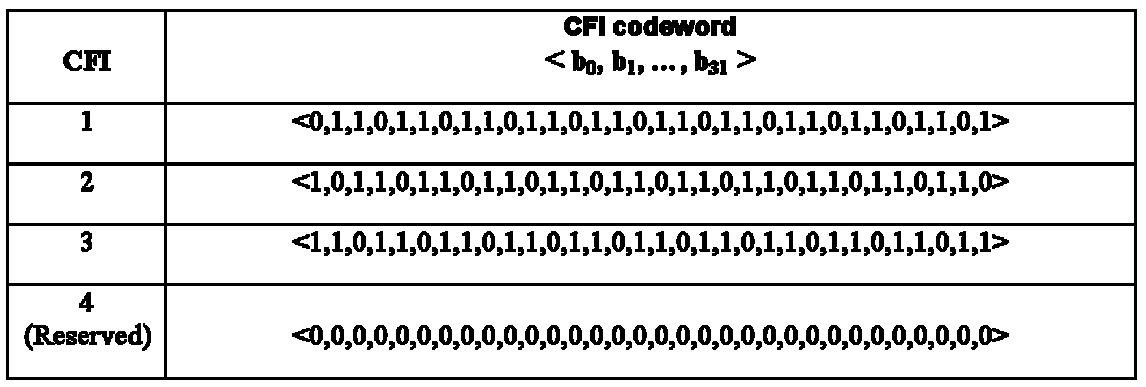
PCFICH 를 통해 전송되는 정보는 시스템 대역폭(system bandwidth)에 따라 다르게 정의될 수 있다. 예를 들면, 시스템의 대역폭이 특정 임계치보다 작은 경우 CFI=1, 2, 3 은 각각 2, 3, 4 개의 OFDM 심볼이 PDCCH를 위해 사용됨을 나타낼 수도 있다.
도 11 은 PCFICH가 전송되는 방식을 나타내는 도면이다. 도 11 에서 도시하는 REG 는, 4개의 부반송파로 구성되어 있고, RS(참조신호)를 제외한 데이터 부반송파로만 구성되어 있으며, 일반적으로 전송 다이버시티(transmit diversity) 기법이 적용될 수 있다. 또한 REG의 위치는, 셀간에 간섭을 주지 않도록 셀마다 (즉, 셀 식별자에 따라서) 주파수 시프트될 수 있다. 추가적으로, PCFICH는 항상 서브프레임의 첫 번째 OFDM 심볼(OFDM 심볼 인덱스 0)에서 전송된다. 이에 따라 수신단에서는 서브프레임을 수신할 때에 먼저 PCFICH의 정보를 확인하여 PDCCH 가 전송되는 OFDM 심볼의 개수를 파악하고 그에 따라서 PDCCH를 통해 전송되는 제어 정보를 수신할 수 있다.
PHICH (Physical Hybrid-ARQ Indicator Channel)
도 12 는 특정 대역폭에서 일반적으로 적용되는 PCFICH 및 PHICH 채널의 위치를 나타내는 도면이다. PHICH 를 통해서 상향링크 데이터 전송에 대한 ACK/NACK 정보가 전송된다. 하나의 서브프레임에서 여러 개의 PHICH 그룹이 만들어지고, 하나의 PHICH 그룹에는 여러 개의 PHICH가 존재한다. 따라서, 하나의 PHICH 그룹에는 여러 개의 단말에 대한 PHICH 채널이 포함된다.
도 12에서 도시하는 바와 같이, 여러 개의 PHICH 그룹에서 각 단말기에 대한 PHICH 할당은, PUSCH 자원 할당(resource allocation)의 가장 낮은 물리자원블록(Physical Resource Block; PRB) 인덱스(lowest PRB index)와, 상향링크 그랜트 PDCCH 를 통해 전송되는 복조참조신호(Demodulation RS; DMRS)를 위한 순환시프트(Cyclic Shift) 인덱스를 이용하여 이루어진다. DMRS 는 상향링크 참조신호이며, 상향링크 데이터의 복조를 위한 채널 추정을 위해서 상향링크 전송과 함께 제공되는 신호이다. 또한, PHICH 자원은  와 같은 인덱스 쌍(index pair)를 통해서 알려지게 되는데, 이때
  는 PHICH 그룹 번호(PHICH group number)를 의미하고,
  는 해당 PHICH 그룹 내에서의 직교 시퀀스 인덱스(orthogonal sequence index)를 의미한다. 또한, PHICH 그룹의 개수는 상위계층에 의해서 설정되며, PHICH 그룹의 개수는 물리방송채널(PBCH)을 통해 전송되는 PHICH 자원의 양에 대한 정보로부터 도출될 수 있다.
도 13은 PHICH 그룹이 매핑되는 하향링크 자원요소 위치를 나타내는 도면이다. PHICH 그룹은 PHICH 구간(duration)에 따라서 도 13 과 같이 하나의 서브프레임 내에서 상이한 시간 영역 (즉, 상이한 OFDM 심볼) 상에서 구성될 수도 있다. 도 13 에서 PHICH 구간이 1 인 경우에는 OS0(OFDM 심볼 인덱스 0) 에서 PHICH가 전송되고, PHICH 구간이 2 인 경우에는 OS1 및 OS2 (OFDM 심볼 인덱스 0 및 1) 에서 PHICH가 전송되고, PHICH 구간이 3 인 경우에는 OS0 내지 2(OFDM 심볼 인덱스 0 내지 2) 에서 PHICH가 전송되는 것을 나타낸다.
제어 채널 및 데이터 채널의 보호
발전된 무선 통신 시스템(예를 들어, LTE-A 또는 LTE 릴리즈-10 시스템)에서는 특정 셀의 전송을 특정 자원에서 제한하거나 특정 셀의 빔 방향을 조정하는 등의 셀간 간섭 조정(ICIC)을 수행하여 데이터 레이트를 증가시키고 셀-경계(cell-edge)에서의 수율(throughput)을 증가시키는 방안이 논의되고 있다.
도 14 은 이종 네트워크 무선 통신 시스템의 일례를 나타내는 도면이다. 이종 네트워크(heterogeneous network)라는 용어는, 동일한 RAT(Radio Access Technology)를 사용하더라도 매크로 기지국(Macro eNB) 및 마이크로 기지국(Micro eNB)가 공존하는 네트워크를 의미한다. 매크로 기지국은 넓은 커버리지 및 높은 전송 전력을 가지고, 무선 통신 시스템의 일반적인 기지국을 의미한다. 매크로 기지국을 매크로 셀이라고 칭할 수도 있다. 한편, 마이크로 기지국은, 예를 들어, 마이크로 셀(cell), 피코 셀(pico cell), 펨토 셀(femto cell), 홈(home) eNB(HeNB), 중계기(relay) 등으로 칭하여질 수도 있다. 도 14 에서는 피코 기지국을 예시적으로 나타낸다. 마이크로 기지국은 매크로 기지국의 소형 버전으로 매크로 기지국의 기능을 대부분 수행하면서 독립적으로 작동할 수 있으며, 매크로 기지국이 커버하는 영역 내에 설치(overlay)되거나 매크로 기지국이 커버하지 못하는 음영 지역에 설치 될 수 있는(non-overlay) 유형의 기지국이다. 마이크로 기지국은 매크로 기지국에 비하여 좁은 커버리지 및 낮은 전송 전력을 가지고 보다 적은 개수의 단말을 수용할 수 있다.
단말의 액세스 제한 여부에 따라 마이크로 기지국은 두 가지 타입으로 분류될 수 있다. 첫 번째 타입은 CSG(Closed Subscriber Group) 마이크로 기지국이고, 두 번째 타입은 OA (Open Access) 또는 OSC(Open Subscriber Group) 마이크로 기지국이다. CSG 마이크로 기지국은 허가 받은 특정 단말들만 서빙할 수 있고, OSG 마이크로 기지국은 별도의 액세스 제한 없이 모든 단말들을 서빙할 수 있다.
도 14 과 같은 이종 네트워크에서 매크로 기지국에 의하여 서빙받는 단말이 마이크로 기지국에 인접한 경우에, 마이크로 기지국으로부터의 강한 하향링크 신호로 인하여 매크로 단말이 수신하는 매크로 기지국으로부터의 하향링크 신호에 간섭이 발생할 수 있다. 또는, 마이크로 기지국에 의해서 서빙받는 단말이 매크로 기지국의 하향링크 신호로 인하여 강한 간섭을 받을 수도 있다.
또한, 도 14에서는 피코 셀에서 셀 범위 확장(Cell Range Expansion; CRE)이 적용되는 경우를 나타낸다. CRE는 피코 셀의 범위를 강제적으로 확장함으로써 매크로 셀의 부담을 줄이고 시스템 전체적인 수율을 증가시키기 위한 기법이다. 도 14 의 예시에서와 같이 피코 셀에 의해 서빙 받는 단말(Pico UE)이 피코 셀의 범위 확장 영역(range expansion area)에 위치하는 경우에, Pico UE가 매크로 셀로부터의 강한 간섭을 받을 수 있다. 구체적으로 Pico UE가 피코 셀로부터 수신하는 제어 채널 및 데이터 채널의 성능이 크게 감소할 수 있다. 이와 같이 하나의 셀이 인접한 셀로부터 강한 간섭을 받는 경우에, 인접 셀이 일부 자원 영역(예를 들어, 일부 서브프레임)에서 자신의 전송을 제한하여 간섭을 완화/제거하는 셀간 간섭 조정(ICIC)이 수행될 수 있다.
예를 들어, 간섭을 받는 셀(도 14의 예시에서 피코 셀)에 연결된 단말을 위해서 간섭을 주는 셀(도 14의 예시에서 매크로 셀)이 특정 자원 영역에서 전송을 수행하지 않는 방안(즉, 널(null) 신호가 전송되는 것 또는 사일런싱(silencing)되는 것으로도 표현할 수 있음)이 적용될 수 있다. 사일런싱 동작의 일례로서, 공격 셀이 특정 서브프레임을 MBSFN 서브프레임으로 설정(configure)할 수 있다. MBSFN 서브프레임으로 설정되는 하향링크 서브프레임에서는 제어 영역에서만 신호가 전송되고 데이터 영역에서는 신호가 전송되지 않는다. 사일런싱 동작의 다른 일례로서, 간섭을 주는 셀이 특정 서브프레임을 ABS(Almost Blank Subframe) 또는 ABS-with-MBSFN 으로 설정할 수도 있다. ABS 는 하향링크 서브프레임의 제어 영역 및 데이터 영역에서 CRS 만을 전송하고, 그 외의 제어 정보 및 데이터는 전송되지 않는 서브프레임을 의미한다. 다만 ABS 에서도 PBCH(Physical Broadcast CHannel), PSS(Primary Synchronization Signal), SSS(Secondary Synchronization Signal) 등의 하향링크 채널 및 하향링크 신호는 전송될 수 있다. ABS-with-MBSFN 는 전술한 ABS 에서 데이터 영역의 CRS 도 전송되지 않는 경우를 의미한다.
여기서, 사일런싱이 수행되는 특정 자원 영역은 시간 자원 및/또는 주파수 자원으로 표현될 수 있다. 예를 들어, 사일런싱되는 시간 자원 위치는, 전체 시간 영역, 특정 서브프레임, 특정 슬롯, 특정 OFDM 심볼 단위 중 하나 이상의 조합에 의해서 결정될 수 있다. 예를 들어, 사일런싱되는 주파수 자원 위치는, 전체 주파수 대역, 특정 반송파 (복수개의 반송파가 사용되는 반송파 병합(carrier aggregation)의 경우), 특정 자원블록, 특정 부반송파 단위 중 하나 이상의 조합에 의해 결정될 수 있다. 이에 따라, 사일런싱이 수행되는 자원 영역이 자원요소(RE) 단위에 이르기까지 명확하게 특정될 수 있다.
이와 같이 특정 자원에서는 간섭을 주는 셀의 전송을 제한함으로써 ICIC의 목적을 어느 정도는 달성할 수 있지만, 상기 특정 영역을 제외한 나머지 영역에서는 간섭을 주는 셀로부터의 강한 간섭이 여전히 존재할 수 있다. 따라서, 이와 같은 사일런싱 기법과 함께 또는 별도로 CoMP 동작을 통해서 ICIC를 적용하는 것을 고려할 수 있다.
CoMP 동작은 크게 JP(Joint Processing) 및 CS/CB(Coordinated Scheduling / Coordinated beamforming)로 나눌 수 있다. 여기서 CS/CB 기법은 CoMP 협력 세트 내의 셀들의 조정을 통해 셀간 간섭을 줄이는 방안으로서 이용될 수 있다.
도 15을 참조하여 CB 동작의 일례에 대하여 설명한다. CB 기법을 이용하면, 서로 다른 셀들의 조정을 통해 각 셀의 빔 방향을 조절하여 셀간 간섭을 줄이거나 수율을 높일 수 있다. 도 15 의 예시에서 eNB1이 간섭을 주는 셀이고 eNB2가 간섭을 받는 셀인 것을 가정한다. eNB1이 eNB2에게 주는 간섭을 줄이기 위해서 eNB2 가 영향을 받지 않는 방향으로 eNB1의 빔 방향을 조정할 수 있다. 빔 방향의 조정은 PMI 제한을 통해서 수행될 수 있으며, 도 15 의 예시에서는 PMI0, PMI1, PMI3, PMI6 을 사용하고 나머지 PMI는 사용하지 않는 것을 나타낸다. 이에 따라, PMI0, PMI1, PMI3, PMI6 을 사용한 경우의 빔 방향에 위치하지 않는 단말에 대해서 eNB1이 서비스를 제공하지 못할 수 있다. 그 대신, eNB2의 입장에서는 eNB1의 빔 방향이 eNB2의 셀 내의 단말들에게 미치지 않게 됨으로써, eNB2는 eNB1으로부터의 간섭 없이 자신의 단말들과의 통신을 원활하게 수행할 수 있게 된다.
여기서, 현재 LTE 및 LTE-A 시스템에서는 빔 방향의 제한은 데이터 채널에 해당하는 자원에서만 적용될 수 있으며, 제어 채널에 해당하는 자원에서는 빔 방향을 제한하는 것이 불가능하다. 예를 들어, 하향링크 데이터 채널(PDSCH)의 처리에서는 프리코딩 처리를 이용하여 빔 방향을 조절함으로써 특정 단말에 대한 양호한 채널을 통해서 데이터 전송이 수행되도록 정의하고 있는 반면, 하향링크 제어 채널(PDCCH)의 경우에는 셀 내의 모든 단말들이 수신할 수 있도록 전 방향으로 전송되어야 하므로 PDCCH의 처리에 프리코딩이 적용되지 않는 것으로 정의하고 있다. 따라서, 전술한 바와 같이 CB 기법을 적용하더라도 간섭을 주는 셀의 제어 채널의 빔 방향을 조정할 수 없게 된다. 예를 들어, CoMP 협력 세트 내의 2 셀의 서브프레임 경계(boundary)가 일치하는 경우에는 2 셀의 각각의 제어 채널이 서로 충돌하여 제어 채널의 성능을 보장할 수 없고, 서브프레임 경계가 일치하지 않는 경우에는 하나의 셀의 제어 채널이 다른 하나의 셀의 제어 채널 및/또는 데이터 채널에 간섭을 주게 되어 제어 채널/데이터 채널의 성능을 보장할 수 없게 된다.
이와 같이 CB 기법을 이용한 ICIC는 도 14 과 같은 매크로-피코(매크로 셀의 전송이 피코 셀에 대해서 강한 간섭으로 작용하는 경우)와 같은 이종 네트워크에서 더욱 문제될 수 있다. 예를 들어, 매크로 셀의 제어 채널에 대한 빔 방향 조정이 수행되지 않음으로써 피코 셀의 시스템 성능이 크게 훼손되는 문제가 발생할 수 있다.
전술한 바와 같은 다양한 ICIC 기법(예를 들어, 간섭을 주는 셀의 전송을 특정 자원 영역에서 제한하거나 또는 간섭을 주는 셀의 빔 방향을 조정하는 등의 기법)을 적용하더라도 간섭을 주는 셀로부터의 간섭으로 인해 간섭을 받는 셀의 성능이 크게 훼손되는 경우가 여전히 발생하게 된다. 따라서, 본 발명에서는 이러한 문제를 해결하는 방안을 제안한다.
종래의 일반적인 하향링크 서브프레임 구조는 상기 도 3 과 같이 하나의 서브프레임의 처음 몇 개의 OFDM 심볼들을 제어 채널의 전송에 이용되는 제어 영역으로 정의하고 나머지 OFDM 심볼들을 데이터 채널의 전송에 이용되는 데이터 영역으로 정의한다. 본 발명에서는, 특정 셀의 하향링크 서브프레임의 제어 영역과 데이터 영역 사이에 널(Null) 영역(널 신호가 전송되는 또는 아무런 신호가 전송되지 않는 OFDM 심볼(들))을 정의하는 것을 제안한다. 서브프레임의 제어 영역과 데이터 영역의 사이는, 하나의 서브프레임 내의 제어 채널과 데이터 채널 사이, 또는 하나의 서브프레임과 앞/뒤로 연속하는 서브프레임에서 상기 하나의 서브프레임의 제어 채널(또는 데이터 채널)과 상기 연속하는 서브프레임의 데이터 채널(또는 제어 채널)사이를 의미할 수 있다. 또한, 상기 특정 셀은 간섭을 주는 셀일 수도 있고 간섭을 받는 셀일 수도 있다. 이와 같이 하향링크 서브프레임을 구성함으로써 하향링크 제어 채널 및 데이터 채널을 다른 셀의 간섭으로부터 보호할 수 있다.
본 발명에서 제안하는 널 영역을 포함하는 하향링크 서브프레임 구성은, 특정 셀이 데이터 채널의 시작 위치 또는 종료 위치를 시그널링하는 방법으로 구현될 수도 있고, 또는 널 영역을 구성하는 OFDM 심볼 개수 자체를 시그널링하는 방법으로 구현될 수도 있다.
기존의 LTE 또는 LTE-A 시스템의 제어 채널 중에서 PCFICH는, 하나의 서브프레임에서 PDCCH의 전송에 이용되는 OFDM 심볼의 개수에 대한 정보(Control Channel Format Indication; CCFI)를 나르는 채널이다. PDCCH전송에 이용되는 OFDM 심볼의 개수는 예를 들어 1, 2 또는 3 이 될 수 있다. 따라서, 단말의 입장에서는 PCFICH를 통해 전송되는 CFI(control format indicator) 정보를 디코딩하여 제어 채널 전송에 이용되는 OFDM 심볼 개수를 알 수 있다. 또한, 기존의 LTE 또는 LTE-A 시스템에서 제어 채널의 시작 위치는 서브프레임의 첫 번째 OFDM 심볼(또는 OFDM 심볼 인덱스 0)로 정의되어 있으므로, CFI 정보를 통해 하나의 서브프레임의 처음 몇개의 OFDM 심볼이 제어 채널 전송이 이용되는지를 결정할 수 있다. 이와 같이 단말은 PCFICH 를 통해서 제어 채널의 시작 위치 및 종료 위치를 결정할 수 있다. 또한, 기존의 LTE 또는 LTE-A 시스템에서 데이터 채널의 시작 위치는 제어 채널의 종료 위치 바로 다음의 OFDM 심볼인 것으로 묵시적으로(implicitly) 결정된다. 즉, 데이터 채널의 시작 위치에 대한 정보가 별도로 전송되지 않고, PCFICH 디코딩의 결과에 따라 간접적으로 데이터 채널 시작 위치가 결정될 수 있다.
그러나, 본 발명에서 제안하는 바와 같이 제어 채널 및 데이터 채널을 보호하기 위해서 제어 채널과 데이터 채널의 사이에 널 영역을 삽입하면, 이에 따라 데이터 채널의 시작 위치를 기존과 같이 제어 채널의 종료 위치로부터 유추해내는 방법이 그대로 적용될 수 없다. 따라서, 하향링크 서브프레임에서 데이터 채널의 시작 위치(및/또는 종료 위치)를 단말이 알 수 있도록 하는 새로운 방안을 정의하는 것이 필요하다.
실시예 1
본 실시예는 간섭을 주는 셀의 서브프레임이 널 영역을 포함하는 경우에 대한 것이다.
도 16 는 본 발명의 일 실시예에 따른 서브프레임 구성을 나타내는 도면이다. 도 16 의 예시에서는 매크로 셀이 간섭을 주는 셀이고 피코 셀이 간섭을 받는 셀이라고 가정한다. 또한, 매크로 셀과 피코 셀의 서브프레임 경계가 일치하는 것을 가정한다. 서브프레임 경계가 일치한다는 것은 매크로 셀의 서브프레임의 시작 및 종료 시점이 피코 셀의 서브프레임의 시작 및 종료 시점과 동일하다는 의미이다. 또한, 도 16 의 예시에서 매크로 셀의 하향링크 전송 주파수 자원은 피코 셀의 하향링크 전송 주파수 자원과 겹치는 것을 가정한다. 이는, 예를 들어, 매크로 셀과 피코 셀의 하향링크 전송 자원 블록이 동일한 주파수 대역에 존재하는 것을 의미한다.
도 16에서 도시하는 바와 같이, 매크로 셀의 서브프레임에는 널 영역(또는 null symbols)이 포함될 수 있다. 널 영역은 제어 채널이 전송되는 영역(control region) 및 데이터 채널이 전송되는 영역(data region)의 사이에 위치할 수 있다. 이와 같이 매크로 셀의 서브프레임에 널 영역을 삽입하면, 피코 셀의 제어 채널이 보호될 수 있다. 즉, 매크로 셀의 널 영역에 대응하는 피코 셀의 제어 영역은 매크로 셀로부터의 간섭을 받지 않게 된다.
도 16 의 예시에서는 매크로 셀의 제어 채널 전송 OFDM 심볼의 개수가 1 인 것을 가정하였다. 이와 같이 매크로 셀의 제어 채널 전송 OFDM 심볼의 개수를 줄이는 경우로서 다음과 같은 상황을 고려할 수 있다.
예를 들어, 도 14에서와 같이 피코 셀의 영역이 확장되는 경우에 피코 셀이 서빙하는 단말의 개수는 증가되는 반면 매크로 셀이 서빙하는 단말의 개수는 줄어들 수 있다. 이 경우, 서빙하는 단말의 개수가 제한되는 만큼 매크로 셀이 단말들에게 전송해야 하는 제어 채널의 부하도 줄어들기 때문에, 하향링크 서브프레임에서 제어 채널 전송에 필요한 OFDM 심볼의 개수(즉, 제어 영역)을 줄일 수 있을 가능성이 높다.
또한, 본 실시예는 CB 기법이 적용되지 않는 경우에도 유용하게 이용될 수 있지만, 매크로 셀이 빔 방향을 제한하여 셀간 간섭을 조정하는 경우에 바람직하게 이용될 수 있다. 예를 들어, 매크로 셀이 PMI 제한 등을 통하여 빔 방향을 제한하면, 매크로 셀이 서빙할 수 있는 단말의 개수가 빔 방향이 제한되지 않는 경우에 비하여 제한될 수 있다. 서빙하는 단말의 개수가 제한되는 만큼 매크로 셀이 단말들에게 전송해야 하는 제어 채널의 부하도 줄어들기 때문에, 하향링크 서브프레임에서 제어 채널 전송에 필요한 OFDM 심볼의 개수(즉, 제어 영역)을 줄일 수 있을 가능성이 높다.
한편, 피코 셀의 제어 채널은 3 개의 OFDM 심볼을 통해 전송될 수 있다. 매크로 셀의 서브프레임이 널 영역을 포함하더라도 매크로 셀의 첫 번째 OFDM 심볼(OFDM 심볼 인덱스 0)에서 전송되는 제어 채널로 인하여, 피코 셀의 첫 번째 OFDM 심볼의 제어 채널이 강한 간섭을 받을 수 있다. 피코 셀의 첫 번째 OFDM 심볼에는 CFI 정보를 나르는 PCFICH가 전송되기 때문에, 피코 셀의 단말이 매크로 셀의 간섭으로 인하여 PCFICH 디코딩을 올바르게 하지 못하여 피코 셀의 제어 채널 전송 OFDM 심볼의 개수를 올바르게 파악하지 못하면, 피코 셀의 단말이 제어 채널을 올바르게 디코딩하지 못할 수도 있다. 따라서, 피코 셀의 단말이 PCFICH 디코딩을 올바르게 수행하지 못하는 경우에도, 피코 셀의 단말이 피코 셀의 제어 채널 전송 OFDM 심볼의 개수를 알 수 있도록 하는 방안으로 다음의 방법을 사용할 수 있다. 단말은 다른 제어 채널의 전송 OFDM 심볼의 개수로부터 간접적으로 제어 채널(PDCCH)의 전송 OFDM 심볼 개수를 유추할 수 있다. 일례로서, 단말은 PHICH 정보를 통하여 묵시적으로 제어 채널 전송 OFDM 심볼의 개수를 파악할 수 있다. 구체적으로, PHICH가 전송되는 OFDM 심볼의 개수(또는 PHICH 구간)는 PBCH를 통하여 단말에게 알려질 수 있고, 단말은 PHICH가 3 개의 OFDM 심볼을 통해서 전송된다면 제어 채널 역시 3 개의 OFDM 심볼을 통해서 전송되는 것으로 인식할 수 있다. 또는, 제어 채널 전송 OFDM 심볼의 개수는 피코 셀이 단말에게 상위 계층(예를 들어, RRC) 시그널링을 통해 알려줄 수도 있고, 별도의 시그널링 없이 미리 정해진 값이 이용되는 것으로 정의할 수도 있다.
한편, 매크로 셀은 피코 셀이 제어 채널을 전송하는 영역 중에서 매크로 셀이 제어 정보를 전송하는 첫 번째 OFDM 심볼을 제외한 나머지 심볼들(두 번째 및 세 번째 OFDM 심볼)을 널링하여, 피코 셀의 제어 채널에 가해지는 간섭을 줄일 수 있고, 이에 따라 피코 셀은 자신이 서빙하는 단말이 제어 채널을 올바르게 디코딩할 수 있도록 제어 채널을 구성 및 전송할 수 있다. 예를 들어, 피코 셀은 제어 채널의 CCE 조합 레벨(aggregation level)을 높이는 등의 방법을 적용할 수 있다.
이 때, 매크로 셀의 기지국은 셀 내의 스케줄링된 단말들에게 널 영역의 존재 유무 및 널 영역의 시작점 및 종료점 등의 정보를 시그널링하여 줄 필요가 있다. 이에 대해서는 후술하는 실시예 4 에서 구체적으로 설명한다.
실시예 2
본 실시예는 간섭을 받는 셀의 서브프레임이 널 영역을 포함하는 경우에 대한 것이다.
도 17 은 본 발명의 일 실시예에 따른 서브프레임 구성을 나타내는 도면이다. 도 17 의 예시에서는 매크로 셀이 간섭을 주는 셀이고 피코 셀이 간섭을 받는 셀이라고 가정한다. 도 17 에서는 도 16 와 달리 매크로 셀과 피코 셀의 서브프레임 경계가 일치하지 않는 것을 가정한다. 여기서, 매크로 셀의 서브프레임 경계가 피코 셀의 서브프레임 경계에 비하여 (시간상에서 뒤로) 시프트될 수 있다. 도 17 의 예시에서는 매크로 셀의 서브프레임 경계가 피코 셀의 제어 영역 크기(예를 들어, 3 OFDM 심볼) 만큼 시프트된 경우를 나타낸다. 또한, 도 17 의 예시에서 매크로 셀의 하향링크 전송 주파수 자원은 피코 셀의 하향링크 전송 주파수 자원과 겹치는 것을 가정한다. 이는, 예를 들어, 매크로 셀과 피코 셀의 하향링크 전송 자원 블록이 동일한 주파수 대역에 존재하는 것을 의미한다.
도 17 의 예시와 같이 두 셀의 서브프레임 경계가 일치하지 않는 것은, 피코 셀의 제어 채널 보호를 위하여 매크로 셀의 서브프레임 경계를 피코 셀의 제어 채널 영역(예를 들어, 3 OFDM 심볼) 만큼 시프트하는 셀간 간섭 조정의 결과일 수 있다.
여기서, 도 17 에 도시된 매크로 셀의 제어 영역을 제외한 데이터 영역은 사일런싱되는 경우를 가정할 수 있다. 이 경우, 피코 셀의 제어 채널은 매크로 셀로부터의 간섭을 받지 않는 반면, 피코 셀의 데이터 채널의 일부 영역은 매크로 셀의 제어 채널 전송에 의해 간섭을 받을 수 있다. 이 경우에는 피코 셀의 데이터 채널의 성능을 보장하기 위해서, 피코 셀의 서브프레임에서 매크로 셀의 제어 영역과 겹치는 OFDM 심볼들을 널 영역으로 정할 수 있다.
또는, 사일런싱의 적용과 함께 또는 별개로 CB 기법이 적용되는 경우 매크로 셀이 빔 방향을 조정함으로써 매크로 셀의 데이터 채널은 피코 셀의 방향으로 빔이 형성되지 않을 수 있다. 이러한 경우, 피코 셀의 입장에서 피코 셀의 제어 채널은 매크로 셀의 데이터 채널과 겹치지만(도 17 의 매크로 셀의 서브프레임 이전의 서브프레임의 데이터 영역(미도시)), 매크로 셀의 데이터 채널의 빔 방향이 제한되기 때문에 피코 셀의 제어 채널에 작용하는 간섭량이 크게 감소할 수 있다. 그러나, 매크로 셀의 제어 채널에는 빔 방향 제한이 적용되지 않기 때문에, 피코 셀의 데이터 채널 중에서 매크로 셀의 제어 채널과 겹치는 부분은 매크로 셀로부터 강한 간섭을 받을 수 있다. 이 경우에는 피코 셀의 데이터 채널의 성능을 보장하기 위해서, 피코 셀의 서브프레임에서 매크로 셀의 제어 영역과 겹치는 OFDM 심볼들을 널 영역으로 정할 수 있다.
추가적으로, 피코 셀의 서브프레임에 널 영역을 삽입하고 피코 셀의 서브프레임 경계가 시프트되는 또 다른 예시로서, 피코 셀의 제어 영역을 1 OFDM 심볼 또는 2 OFDM 심볼로 제한하는 경우를 가정할 수 있다. 도 18 에서는 피코 셀의 제어 영역이 1 OFDM 심볼로 제한되는 예시를 나타낸다. 이 경우에는, 매크로 셀의 제어 영역을, 제어 영역이 차지할 수 있는 최대 값(즉, 3 OFDM 심볼)에서 피코 셀의 제어 영역의 크기(예를 들어, 1 OFDM 심볼)를 제외한 값(예를 들어, 2 OFDM 심볼)에 따라 구성할 수 있다. 또한, 매크로 셀의 서브프레임 경계가 피코 셀의 제어 영역의 크기(즉, 1 OFDM 심볼) 만큼 시프트되어, 피코 셀의 제어 영역이 보호될 수 있다. 또한, 피코 셀은 매크로 셀의 제어 영역과 겹치는 피코 셀의 제어 영역 다음의 OFDM 심볼들을 널 영역으로 설정할 수 있다.
이 때, 피코 셀의 기지국은 셀 내의 스케줄링된 단말들에게 널 영역의 존재 유무 및 널 영역의 시작점 및 종료점 등의 정보를 시그널링하여 줄 필요가 있다. 이에 대해서는 후술하는 실시예 4 에서 구체적으로 설명한다.
실시예 3
본 실시예는 간섭을 받는 셀의 서브프레임이 널 영역을 포함하는 경우에 대한 것이다.
도 19 는 본 발명의 일 실시예에 따른 서브프레임 구성을 나타내는 도면이다. 도 19 의 예시에서는 매크로 셀이 간섭을 주는 셀이고 피코 셀이 간섭을 받는 셀이라고 가정한다. 도 19 에서는 매크로 셀의 서브프레임 경계가 피코 셀의 서브프레임 경계와 일치하지 않는 경우를 나타낸다. 또한, 도 19 의 예시에서 매크로 셀의 하향링크 전송 주파수 자원은 피코 셀의 하향링크 전송 주파수 자원과 겹치는 것을 가정한다. 이는, 예를 들어, 매크로 셀과 피코 셀의 하향링크 전송 자원 블록이 동일한 주파수 대역에 존재하는 것을 의미한다.
도 19 의 예시는 도 17 또는 도 18 의 예시와 달리 매크로 셀의 서브프레임 경계가 (시간 상에서 앞으로) 시프트되는 경우를 나타낸다. 이 경우에는 피코 셀의 데이터 채널을 보호하기 위해서 널 영역이 피코 셀의 N 번째 서브프레임의 마지막 부분에 위치하게 된다 (즉, 매크로 셀의 N+1 번째 서브프레임의 제어 채널과 겹치는 영역에 널 영역이 설정될 수 있다). 이 경우, 데이터 채널의 종료 위치(또는 널 영역의 시작 위치)를 단말에게 알려줄 필요가 있다.
전술한 실시예 1 내지 3 에서 설명한 본 발명의 다양한 예시들에 따르면, 간섭을 주는 셀 또는 간섭을 받는 셀의 서브프레임의 일부 구간에 다양한 방식으로 널 영역이 설정될 수 있다. 간섭을 주는 셀(또는 간섭을 받는 셀)의 서브프레임에 설정되는 널 영역은 간섭을 받는 셀(또는 간섭을 주는 셀)의 서브프레임의 제어 영역의 전부 또는 일부에 대응할 수 있다. 이와 같이 널 영역을 설정하는 셀에서는 자신이 서빙하는 단말들에게 널 영역의 존재 유무 및 널 영역의 시작점 및 종료점 등의 정보를 알려줄 필요가 있다.
실시예 4
기존의 시스템에서는 제어 채널(PDCCH)의 전송에 이용되는 OFDM 심볼 개수(즉, PDCCH 전송의 종료 위치)를 알려주는 정보를 PCFICH를 통해 알려줄 수 있고, PDCCH 종료 위치의 바로 다음의 OFDM 심볼이 데이터 채널(PDSCH) 전송 시작 위치임을 단말이 묵시적으로 파악할 수 있다. 그러나, 널 영역이 포함되는 경우에는 제어 채널의 종료 위치의 바로 다음 OFDM 심볼이 항상 데이터 채널의 시작 위치가 되는 것이 아닐 수도 있고, 또는 데이터 채널의 종료 위치가 항상 서브프레임의 마지막 OFDM 심볼이 되는 것은 아닐 수도 있으므로, 널 영역의 위치에 대한 정보를 단말에게 알려주는 것이 필요하다.
이를 위하여 기지국이 단말에게 제어 채널의 종료 위치 및/또는 데이터 채널의 시작 위치(또는 종료 위치)를 시그널링하여 줄 수 있으며, 구체적인 방안은 다음과 같다.
현재 LTE 및 LTE-A 시스템에서 다양한 상황(하나 초과의 반송파를 설정받는 단말의 경우, 단일 반송파를 설정받는 단말의 경우, 중계기의 경우 등)에 있어서, 단말(또는 중계기)은 PDCCH의 종료 위치를 시그널링 받거나, PDSCH의 시작 위치를 시그널링 받을 수 있다.
단말이 기지국으로부터 PDCCH의 종료 위치를 시그널링 받는 경우에 본 발명과 같이 널 영역의 적용을 위해서는 추가적으로 PDSCH의 시작 위치(또는 종료 위치)에 대한 시그널링을 받거나, 널 영역의 위치에 대한 정보를 시그널링 받을 수 있다.
여기서, 단말이 기지국으로부터 시그널링 받은 PDCCH의 종료 위치가 PDSCH의 시작 위치를 동시에 의미하는 경우(즉, 종래의 CFI 정보와 같이 PDCCH 종료 위치의 바로 다음 OFDM 심볼이 PDSCH의 시작 위치를 의미하는 경우), 본 발명의 적용을 위해서 단말이 기지국으로부터 널 영역의 위치를 추가적으로 시그널링 받을 수 있다. 예를 들어, PDCCH 종료 위치는 시그널링 받는 값이 실제 PDCCH 종료 위치로 사용되고, PDSCH 실제 시작 위치는 PDCCH의 종료 위치의 바로 다음 OFDM 심볼로 지시되는 PDSCH 시작 위치에 널 영역의 길이를 더한 값에 해당하는 OFDM 심볼로 결정될 수 있다 (도 16 의 매크로 셀 또는 도 17 의 피코 셀의 경우). 다른 예시로서, PDCCH의 종료 위치(또는 PDCCH 전송 OFDM 심볼 개수)가 최대값으로 시그널링 되는 경우, 여기서 널 영역의 길이를 뺀 값에 해당하는 OFDM 심볼 개수가 실제 PDCCH 전송 OFDM 심볼 개수로 결정되고, PDSCH 실제 시작 위치는 최대 값의 PDCCH 종료 위치 바로 다음의 OFDM 심볼로 결정될 수 있다 (도 18 의 피코 셀의 경우).
또는, 단말이 기지국으로부터 시그널링 받은 PDCCH의 종료 위치가 PDSCH의 시작 위치를 동시에 의미하는 경우, 본 발명의 적용을 위해서 단말이 기지국으로부터 PDSCH의 종료 위치를 추가적으로 시그널링을 받을 수 있다. 이 경우, PDCCH의 종료 위치가 PDCCH의 실제 종료 위치가 되고 PDSCH의 시작 위치는 PDCCH의 실제 종료 위치의 바로 다음 OFDM 심볼이 되고, PDSCH의 종료 위치는 시그널링 받은 값에 따라 결정될 수 있다 (도 19의 피코 셀의 경우).
다음으로, 단말이 기지국으로부터 PDSCH의 시작 위치를 시그널링 받는 경우에 본 발명과 같이 널 영역의 적용을 위해서는 추가적으로 PDCCH의 종료 위치를 시그널링 받거나, 널 영역의 위치에 대한 정보를 시그널링 받을 수 있다. 이에 따라, 단말은 PDCCH 전송 영역, 널 영역, PDSCH 전송 영역을 결정할 수 있다. 한편, 도 19 와 같이 널 영역이 서브프레임의 마지막 부분에 위치하는 경우에는 PDSCH 의 종료 위치를 시그널링 받음으로써 널 영역의 위치를 결정할 수도 있다.
전술한 설명에 있어서 기본적으로는 제어 채널(PDCCH)의 종료 위치는 PCFICH 디코딩을 통하여 단말이 파악할 수 있지만, 강한 간섭 등으로 인하여 PCFICH 디코딩이 어려운 경우에는 PBCH를 통해 전송되는 PHICH 정보로부터 간접적으로 제어 채널 전송 OFDM 심볼의 개수를 파악하거나, 상위 계층 시그널링이나 미리-정의된 값을 이용하여 제어 채널 전송 OFDM 심볼의 개수를 파악하는 방안이 적용될 수 있다. 본 발명에서는 이와 같이 다양한 방안을 통해 제어 채널 전송 OFDM 심볼 개수가 결정되고, 이를 바탕으로 단말이 PDCCH 디코딩을 통해 PDSCH 전송 영역에 대한 추가적인 정보를 획득한 후, PDSCH 디코딩을 수행하는 과정을 포함할 수 있다.
또한, 데이터 채널(PDSCH)의 시작 위치 또는 종료 위치, 제어 채널(PDCCH)의 종료 위치, 널 영역의 위치 중 하나 이상이 상위 계층 시그널링(예를 들어, RRC 시그널링)을 통하여 단말에게 제공되거나, 다른 채널(예를 들어, 방송 채널)을 통해서 제공되거나, 또는 미리 정해진 값이 사용될 수도 있다.
위와 같은 제어 채널에 대한 정보, 데이터 채널에 대한 정보, 널 영역에 대한 정보 중 일부로부터 다른 정보를 유추할 수 있는 경우에는 유추가능한 정보를 전달하지 않는 것이 가능하다. 이렇게 함으로써 제어 정보 전달의 오버헤드를 줄이고 네트워크 성능을 향상시킬 수 있다. 예를 들어, 제어 채널의 종료 위치 및 널 영역의 길이에 대한 정보로부터 데이터 채널의 시작 위치가 유추가능한 경우에는 데이터 채널에 대한 정보는 전달되지 않을 수 있다. 또는, 데이터 채널의 시작 위치 및 널 영역의 길이에 대한 정보로부터 제어 채널의 종료 위치가 유추가능한 경우에는 제어 채널에 대한 정보는 전달되지 않을 수도 있다.
실시예 5
하향링크 서브프레임에 널 영역을 적용하는 본 발명의 다양한 실시예들이 적용되는 경우에, 간섭을 주고 받는 기지국들(예를 들어, 매크로 셀과 피코 셀) 간의 셀간 간섭 조정을 위한 정보들이 교환될 필요가 있다. 이러한 정보들은 기지국들 간의 백홀 링크(또는 X2 인터페이스)를 통하여 교환될 수 있으며, 그 구체적인 예시들은 다음과 같다.
한 기지국은 다른 기지국(들)에게 제어 채널 관련 정보를 알려 줄 수 있다. 구체적으로, 제어 채널이 전송되는 OFDM 심볼의 개수 (또는 CFI 값), 제어 채널의 시작 위치 (또는 종료 위치) 등이 시그널링될 수 있다. 또한, 제어 영역만 블랭크되는 서브프레임(즉, 제어 영역이 블랭크(또는 널링)되고 데이터 영역에서만 정보가 전송되는 서브프레임)에 대한 정보가 시그널링될 수도 있다 (이를 control only blank subframe 이라고 칭할 수 있으며, 후술하는 실시예 7 에서 자세한 내용에 대하여 설명한다).
한 기지국은 다른 기지국(들)에게 데이터 채널 관련 정보를 알려 줄 수 있다. 구체적으로, 데이터 채널의 시작 위치 (또는 종료 위치) 등이 시그널링될 수 있다.
한 기지국은 다른 기지국(들)에게 널 영역 관련 정보를 알려 줄 수 있다. 구체적으로, 널 영역의 시작 위치 (또는 종료 위치), 널 영역이 차지하는 OFDM 심볼의 개수 (또는 널 영역의 길이) 등이 시그널링될 수 있다.
위와 같은 제어 채널, 데이터 채널, 널 영역에 대한 정보는 각각 단독으로 다른 기지국에게 전달될 수도 있고, 또는 2 이상의 조합의 형태로 다른 기지국에게 전달될 수도 있다. 또한, 일부의 정보로부터 다른 정보를 유추할 수 있는 경우에는 유추가능한 정보를 전달하지 않는 것도 가능하다. 예를 들어, 제어 채널의 종료 위치 및 널 영역의 길이에 대한 정보로부터 데이터 채널의 시작 위치가 유추가능한 경우에는 데이터 채널에 대한 정보는 전달되지 않을 수 있다. 또는, 데이터 채널의 시작 위치 및 널 영역의 길이에 대한 정보로부터 제어 채널의 종료 위치가 유추가능한 경우에는 제어 채널에 대한 정보는 전달되지 않을 수도 있다.
실시예 6
간섭을 받는 셀(예를 들어, 도 14 의 피코 셀)의 제어 채널이 간섭을 주는 셀(예를 들어, 도 14 의 매크로 셀)의 제어 채널에 의해서 강한 간섭을 받는 경우에, 간섭을 받는 셀의 성능이 크게 저하된다. 따라서, 본 실시예에서는 간섭을 받는 셀의 제어 채널(PDCCH)을 간섭을 주는 셀의 제어 영역(PDCCH 전송 영역)을 피해서 전송하는 방안에 대하여 제안한다. 이하에서 설명하는 다양한 예시들의 이해를 돕기 위해서, 도 16 의 예시에서와 같이 간섭을 주는 셀의 PDCCH가 하향링크 서브프레임의 첫 번째 OFDM 심볼(OFDM 심볼 인덱스 0)에서 강한 간섭을 유발하는 경우를 가정할 수 있다. 그러나, 본 발명의 범위가 이에 제한되는 것은 아니다. 즉, 이하의 예시들은 간섭을 받는 셀의 하향링크 서브프레임의 PDCCH 전송 OFDM 심볼들 중에서 강한 간섭을 받는 특정 OFDM 심볼에서 PDCCH 전송을 위해 사용되는 자원요소(RE)의 개수를 최대한 줄임으로써 간섭의 영향을 최소화하는 방안으로서 적용될 수 있다.
실시예 6-1
본 실시예는 간섭을 받는 셀에서 제어채널요소(CCE) 널링(nulling)을 적용하는 방안에 대한 것이다. 여기서, PDCCH는 하나 이상의 연속하는 CCE의 조합으로 전송되며, 하나의 CCE는 복수개의 자원요소그룹(REG)에 대응하며, 하나의 REG는 복수개의 자원요소(RE)를 포함한다.
본 실시예에 따르면, 간섭을 주는 셀의 PDCCH가 전송되는 OFDM 심볼과 정렬되는 (시간 상 겹치는), 간섭을 받는 셀의 서브프레임의 OFDM 심볼에 속한 REG를 포함하는 CCE를 널링할 수 있다. 널링은 레이트 매칭(rate matching)과 유사한 의미로 이해될 수 있다. CCE를 널링한다는 것은 CCE에 해당하는 RE를 제외하고 PDCCH를 매핑하는 것으로 표현할 수도 있다.
여기서, 각각의 CCE는 물리 자원 상에 매핑되기 이전에 REG 단위로 인터리빙(interleaving)된다. 따라서, 간섭을 주는 셀의 PDCCH 전송 OFDM 심볼과 겹치는 간섭을 받는 셀의 OFDM 심볼에 속한 REG는 복수개의 CCE에 대응할 수 있고, 널링되는 CCE는 복수개의 CCE가 될 수 있다. 이러한 면에서, CCE를 널링하는 본 실시예는 시스템 대역폭이 큰 경우에 비하여 시스템 대역폭이 작은 경우에 보다 효율적으로 동작할 수 있다. 왜냐하면, 시스템 대역폭이 커질 수록 널링되는 CCE의 개수가 증가하고 이에 따라 제어 채널 전송에 사용할 수 있는 자원의 양이 작아질 수 있기 때문이다.
실시예 6-2
본 실시예는 간섭을 받는 셀에서 PHICH 그룹의 최대값을 단말에게 시그널링하는 방안에 대한 것이다. 즉, 기지국은 실제 사용하는 PHICH 그룹의 개수와 무관하게 PHICH 그룹의 개수가 최대값을 가지는 것으로 단말에게 알려줄 수 있다. 또한, PHICH 그룹의 개수가 최대값으로 시그널링되지만, 실제로 PHICH는 하향링크 서브프레임의 첫 번째 OFDM 심볼에서만 전송되도록 제한될 수 있다. 첫 번째 OFDM 심볼에만 PHICH가 집중되어 매핑되므로, PDCCH는 첫 번째 OFDM 심볼에 적게 매핑될 수 있다.
이와 같이 PHICH 그룹의 최대값을 시그널링하는 방안은 전술한 실시예 6-1 과 함께 사용될 수 있다. 즉, 본 실시예 6-2 역시 간섭을 주는 셀의 PDCCH에 의한 간섭이 가장 강할 것으로 예상되는 특정 OFDM 심볼(도 16의 예시에서 첫 번째 OFDM 심볼)에서 PDCCH가 할당되는 자원의 양을 줄이는 방안으로 이용될 수 있다.
실시예 6-3
본 실시예는 간섭을 받는 셀에서 PDCCH가 매핑되는 시작 위치(OFDM 심볼)을 단말에게 시그널링하는 방안에 대한 것이다. PDCCH 시작 OFDM 심볼 위치는 CFI 등의 정보와는 별도로 단말에게 시그널링될 수 있다. 이 경우, PDCCH 종료 OFDM 심볼 위치는 따로 시그널링될 수도 있고, 기존과 같이 CFI를 통해서 알려질 수도 있다. 예를 들어, PDCCH 시작 OFDM 심볼이 두 번째 OFDM 심볼(즉, OFDM 심볼 인덱스 1)인 것으로 시그널링되는 경우에, 첫 번째 OFDM 심볼(즉, OFDM 심볼 인덱스 0)에는 PCFICH 및 PHICH 만이 전송되고 PDCCH의 전송은 없는 것으로 설정될 수 있다.
본 실시예를 확장하여 간섭을 주는 셀의 PDCCH가 전송되는 영역과 겹치지 않는 심볼에 간섭을 받는 셀이 PDCCH를 매핑하는 경우에, 해당 PDCCH의 시작 위치를 알려주는 방안으로서 이용될 수 있다.
실시예 6-4
본 실시예는 간섭을 받는 셀에서 REG (또는 RE) 펑처링(puncturing)을 이용하는 방안에 대한 것이다. 구체적으로, 간섭을 주는 셀의 간섭이 강한 OFDM 심볼 또는 간섭을 주는 셀의 PDCCH 전송 영역과 겹치는 OFDM 심볼에 속한 REG(또는 RE)를 수신단(예를 들어, 단말)에서 펑처링하고 PDCCH를 디코딩할 수 있다. 특정 REG(또는 RE)를 펑처링하고 디코딩한다는 의미는, 송신단에서는 해당 REG(또는 RE)에 정보를 전송하더라도 수신단에서 해당 REG(또는 RE)를 제외하고 디코딩을 시도한다는 의미이다. 예를 들어, 디코딩시에 해당 REG(또는 RE)에서 수신되는 전력을 0 으로 강제로 설정하는 방안 등이 사용될 수 있다. 또한, 송신단에서 PDCCH를 REG에 매핑할 때에 특정 REG(또는 RE)를 펑처링할 수도 있다. 송신단에서의 REG 펑처링은 PDCCH를 REG(또는 RE)에 매핑한 후에 특정 REG(또는 RE)를 전송하지 않는(또는 송신 전력을 0 으로 설정하는) 점에서, 특정 REG(또는 RE)를 제외하고 PDCCH를 매핑하는 널링과 구별될 수 있다.
수신단에서 PDCCH 디코딩에 REG(또는 RE) 펑처링을 사용하는 경우에, 송신단의 입장에서는 간섭의 유무를 고려하지 않고 모든 CCE를 제한없이 사용할 수 있는 장점이 있다. 다만, 특정 REG(또는 RE)가 펑처링되면 그만큼 수신단에서의 PDCCH 디코딩 시에 사용할 수 있는 정보의 양이 줄어들기 때문에, PDCCH 디코딩 성능은 감소할 수 있다.
펑처링되어야 하는 REG(또는 RE)는, 간섭을 주는 셀의 제어 채널의 전송 영역(제어 채널의 시작 위치, 종료 위치 또는 전송 OFDM 심볼 개수)에 대한 정보를 간섭을 받는 셀이 자신의 단말에게 시그널링해 줌으로써 알려줄 수 있다. 또는, 단말이 직접 하향링크 자원 상에서의 간섭을 측정하여, 간섭을 주는 셀의 간섭이 소정의 임계치보다 큰 경우에 해당 자원(또는 해당 OFDM 심볼)에 속한 REG(또는 RE)를 펑처링하고 디코딩하는 방식이 사용될 수도 있다.
실시예 6-5
본 실시예는 간섭을 받는 셀에서 REG (또는 RE) 널링(nulling)을 이용하는 방안에 대한 것이다. 구체적으로, 간섭을 받는 셀이 간섭을 주는 셀의 간섭이 큰 REG(또는 RE)를 널링한 후에 제어 채널들을 위한 REG(또는 CCE) 설정을 수행할 수 있다. 이에 따라, 널링된 REG(또는 RE)를 통해서는 어떠한 정보도 전송되지 않고, 수신단(예를 들어, 단말)에서도 널링된 REG(또는 RE)에는 아무런 정보가 없음을 고려하여 디코딩을 수행할 수 있다. 이러한 점에서 널링은 특정 REG(또는 RE)에 정보가 전송되더라도 해당 REG(또는 RE)를 제외하는 펑처링과 구분될 수 있다.
간섭을 받는 셀의 기지국은 널링되는 REG(또는 RE)에 대한 정보(시간/주파수 상의 위치 정보 등)를 단말에게 상위 계층 시그널링을 이용하여 시그널링하여 줄 수 있다. 예를 들어, 기지국은 단말에게 RRC 시그널링을 통하여 널링 REG(또는 RE)가 무엇인지 나타내는 비트맵을 제공할 수 있다.
이러한 REG(또는 RE)의 널링은 특정 REG(또는 RE)에 강한 간섭이 미치는 경우에 해당 REG(또는 RE)를 송신단에서의 PDCCH 전송에 이용할 REG(또는 RE)에서 배제함으로써 간섭의 영향을 최소화하기 위한 방안으로 사용될 수 있다.
전술한 실시예 6-1 내지 6-5 에서 제안하는 방안들은 독립적으로 적용될 수도 있고, 하나 이상의 방안을 조합하여 간섭을 받는 셀에서의 PDCCH 전송에 이용될 자원의 특정 및 해당 자원 위치를 단말에게 시그널링하여 주는 방안으로서 사용될 수 있다.
실시예 7
본 실시예는 간섭을 주는 셀의 특정 서브프레임에서 제어 영역에서의 전송을 수행하지 않는 방안에 대한 것이다. 동일한 의미를 달리 표현하자면, 특정 서브프레임의 널 영역이 해당 서브프레임의 제어 영역의 전부를 포함하는 것이라고 표현할 수 있다.
도 20은 본 발명에 따른 셀간 간섭 조정의 일 실시예를 설명하기 위한 도면이다. 도 20 에서는 CB 기법의 적용의 일례를 나타내며, 간섭을 주는 셀이 eNB1 이고 간섭을 받는 셀이 eNB2 임을 가정한다. eNB1 은 PMI 세트 별로 상이한 방향으로 빔 방향을 조정할 수 있다. eNB1 은 eNB2에게 이용가능한 서브프레임 세트를 X2 인터페이스를 통한 시그널링의 방식으로 알려줄 수 있다. 이러한 이용가능한 서브프레임 세트는, eNB2가 eNB1으로부터의 간섭 특정이 일정한(또는 동일한) 것으로 가정할 수 있는 서브프레임들에 해당할 수 있다. 또한, 이용가능한 서브프레임 세트의 시그널링은 해당 서브프레임을 나타내는 비트맵 형식으로 구성될 수 있다. eNB1으로부터 이용가능한 서브프레임 세트에 대한 정보를 수신한 eNB2는, 자신의 셀 내의 단말들에게 측정(measurement)을 수행하도록 시그널링하여 줄 수 있다. 여기서, 단말이 측정을 수행할 서브프레임은, eNB2이 eNB1으로부터 수신한 이용가능한 서브프레임 세트 중의 일부 또는 전부 서브프레임으로 설정될 수 있다.
한편, 도 20 에서 나타내는 바와 같이, eNB2는 eNB1의 전송전력 조정 또는 PMI 세트 사용 조정 등에 대한 요청을 eNB1에게 시그널링할 수 있다. 이러한 요청 시그널링은 eNB1이 특정 서브프레임에서의 전송 전력을 낮추거나, eNB2가 특정 PMI 세트를 사용하여 줄 것을 eNB2가 eNB1에게 요청하는 정보로 구성될 수 있다. 또한, 이러한 시그널링은 X2 인터페이스를 통하여 수행될 수 있다. 이에 따라, eNB1은 eNB2의 요청 정보를 고려하여 특정 서브프레임에서 특정 빔 패턴(즉, 특정 PMI 세트의 사용)을 적용할 수 있다. 또한, eNB1은 자신의 셀 내의 단말들에게 이에 대한 정보를 제공할 수 있다. 즉, eNB1은 단말에게 특정 PMI 세트에서만 PMI를 선택하도록 시그널링할 수 있고(즉, PMI 제한), 또는 해당 PMI를 사용하는 단말에게 eNB2의 요청 정보를 고려하여 결정된 서브프레임을 스케줄링하여 줄 수도 있다. 전술한 바와 같이 간섭을 주고 받는 셀들에서의 빔 방향 조정 또는 이용가능한 서브프레임 세트의 교환 등의 동작은 도 20 의 예시에만 적용되는 것이 아니라, 본 발명의 다양한 예시들에 적용될 수 있다.
이와 같이 간섭을 주는 셀에서 CB 기법을 적용하여 빔 방향을 조정하는 경우에도, CB는 데이터 영역에서 전송되는 신호에만 유효하게 적용가능하고, 제어 영역에서 전송되는 신호에는 빔 패턴을 제한할 수가 없다. 따라서, 도 20의 예시에서 eNB1에서 빔 패턴을 조정하더라도 eNB1의 제어 영역의 신호는 여전히 eNB2에게 강한 간섭으로 작용할 수 있다.
본 실시예에서는 간섭을 주는 셀의 제어 영역에서의 신호로 인한 간섭을 줄이기 위해서, 간섭을 주는 셀이 특정 서브프레임에서 제어 영역에서의 전송을 수행하지 않는 방안을 제안한다. 하향링크 서브프레임에서 처음 1, 2 또는 3 개의 OFDM 심볼 구간을 제어 영역으로 설정할 수 있고, (널 영역이 없는 경우에) 나머지 구간을 데이터 영역으로 설정할 수 있다 (도 3 참조). 여기서, 제어 영역에서 전송을 수행하지 않는다는 것은 제어 영역에 PCFICH, PHICH, PDCCH 등의 제어 채널을 매핑시키지 않는 것을 의미할 수도 있고, 제어 영역을 블랭킹(blanking) 또는 널링(nulling)하는 것으로 표현할 수도 있다. 이 경우에도 제어 영역의 제어 신호 (또는 제어 채널) 만이 전송되지 않고, 제어 영역에서 참조신호(RS)는 전송될 수 있다.
여기서, 제어 영역이 블랭킹/널링되는 서브프레임의 세트는 eNB1이 eNB2에게 시그널링해 주는 이용가능한 서브프레임 세트의 부분집합(subset)으로 구성될 수 있다. 도 20의 예시에서는 X2 인터페이스를 통해 시그널링되는 이용가능한 서브프레임 세트에서 eNB2는 eNB1의 간섭이 일정한(또는 동일한) 것을 가정할 수 있다. 예를 들어, eNB2 는 이용가능한 서브프레임 세트에서 eNB1이 특정 PMI 세트만을 제한적으로 사용하는 것으로 해석할 수도 있고, 이러한 경우, eNB1이 사용하는 PMI 세트 별로 이용가능한 서브프레임 세트가 대응되고, eNB1은 eNB2에게 복수개의 서브프레임 세트를 시그널링할 수도 있다.
이와 같이 특정 서브프레임에서 간섭을 주는 셀이 제어 영역에서의 전송을 수행하지 않는 경우에, PDCCH는 기존의 정의에 따라 (즉, 하향링크 서브프레임의 제어 영역에서) 전송될 수 없다. 또한, 해당 서브프레임에서 전송되는 데이터 채널을 단말이 올바르게 수신/디코딩하기 위해서는, 데이터 채널의 전송에 대한 제어 정보를 나르는 제어 채널(특히, PDCCH)이 단말에게 전송될 필요가 있다. 따라서, 본 발명에서는 특정 서브프레임에서 제어 영역의 전송이 없는 경우에도, 제어 정보(또는 제어 채널)를 단말에게 전송하는 방안에 대하여 제안한다.
일례로서, 간섭을 주는 셀에서 간섭을 줄이기 위해 특정 서브프레임에서 제어 영역의 전송은 수행하지 않고, 상기 특정 서브프레임의 데이터 전송을 위해 필요한 제어 정보는 다른 서브프레임을 통해서 미리 전송할 수 있다. 구체적인 예시로서, 도 20의 예시에서 eNB1의 제어 영역에 의한 간섭을 줄이기 위해서 eNB1은 eNB2에게 X2 인터페이스를 통해서 시그널링해주는 이용가능한 서브프레임 세트의 제어 영역에서 전송을 수행하지 않을 수 있다. 제어 영역 전송이 수행되지 않는 서브프레임은, 예를 들어, 이용가능한 서브프레임 세트를 나타내는 비트맵에서 1 로 표시된 서브프레임에 해당할 수 있고, eNB1이 빔 방향의 제한을 수행하는 서브프레임에 해당할 수 있다. 이 경우, 비트맵에서 1 로 표시된 서브프레임에서의 데이터 영역 전송에 대한 제어 정보는 다른 서브프레임(예를 들어, 비트맵에서 0 으로 표시된 서브프레임)에서 전송될 수 있다. 또한, 제어 영역 전송이 없는 서브프레임에서의 데이터 전송에 대한 제어 정보는 해당 서브프레임보다 앞선 서브프레임 중에서 제어 영역 전송이 수행되는 서브프레임에서 전송될 수 있다. 또한, 제어 영역 전송이 수행되는 하나의 서브프레임에서, 제어 영역 전송이 수행되지 않는 다른 하나 또는 복수개의 서브프레임에서의 데이터 전송에 대한 제어 정보가 전송될 수도 있다.
다른 예시로서, 간섭을 주는 셀에서 간섭을 줄이기 위해 특정 서브프레임에서 제어 영역의 전송은 수행하지 않고, 상기 특정 서브프레임의 데이터 전송을 위해 필요한 제어 정보는 상기 특정 서브프레임의 데이터 영역을 통해서 데이터와 함께 전송할 수 있다. 구체적으로, 특정 서브프레임의 제어 영역의 OFDM 심볼들은 널링하고 (제어 영역의 참조신호(RS)는 전송될 수 있음), 그 특정 서브프레임에서 제어 정보는 데이터 영역에서 데이터와 함께 프리코딩되어 전송될 수 있다. 이에 따라, 특정 빔 방향으로 제어 정보의 전송이 가능해지고, 이에 따라 제어 정보에 의한 간섭을 줄일 수 있다. 이와 같이 하향링크 서브프레임의 데이터 영역에서 전송되는 제어 채널이 새롭게 정의될 수 있고, 이를 기존의 하향링크제어채널(PDCCH)와 구분하기 위해서 발전된-PDCCH(E-PDCCH)라고 칭할 수 있다. 또는, 중계기를 위한 제어 채널로서 제안되는 R-PDCCH (데이터 영역에서 전송되며 중계기로의 PDSCH 전송에 대한 스케줄링 정보 등을 나르는 채널, 도 9 참조)가 이용될 수도 있다. 도 20의 예시에서, eNB1이 eNB2에게 X2 인터페이스를 통해 전송하는 이용가능한 서브프레임 세트의 비트맵 중에서 1 로 표시되는 (즉, 제어 영역 전송이 수행되지 않는) 서브프레임들 중 하나의 서브프레임의 데이터 영역에서 E-PDCCH가 전송될 수 있고, 상기 E-PDCCH를 통해서 비트맵에서 1 로 표시되는 다른 하나 또는 복수개의 후속 서브프레임들에서의 데이터 전송에 대한 제어 정보가 전송될 수 있다.
본 실시예에서 설명한 사항을 특정 서브프레임의 널 영역이 해당 서브프레임의 제어 영역의 전부를 포함하는 관점에서 설명할 수도 있다. 예를 들어, 간섭을 주고 받는 셀들의 서브프레임 경계가 일치하고 제어 영역의 길이가 동일한 경우를 가정할 수 있다. 이 경우에, 간섭을 주는 셀의 하향링크 서브프레임의 제어 영역의 전부에 널 영역이 적용됨으로써 주변 셀에 대한 간섭을 줄이고, 간섭을 주는 셀의 데이터 전송에 대한 제어 정보는 데이터 영역에서 전송되는 새로운 형식의 제어 채널(예를 들어, E-PDCCH)를 이용하여 전송할 수 있다. 또는, 간섭을 주는 셀의 하향링크 서브프레임에서 제어 영역의 전송이 수행되고 이로 인하여 간섭을 받는 셀의 제어 영역의 전부가 강한 간섭을 받는 경우에, 간섭을 받는 셀에서 해당 하향링크 서브프레임의 제어 영역 전부에 널 영역을 적용함으로써 간섭의 영향을 최소화하고, 간섭을 받는 셀의 데이터 전송을 위한 제어 정보는 데이터 영역에서 전송되는 새로운 형식의 제어 채널(예를 들어, E-PDCCH)를 이용하여 전송할 수 있다.
도 21은 본 발명의 일 실시예에 따른 널 영역을 포함하는 하향링크 서브프레임의 송수신 방법을 설명하기 위한 흐름도이다.
단계 S2110 에서 기지국은 단말에게 하향링크 서브프레임에 포함되는 널 영역의 위치를 결정할 수 있는 정보를 제공할 수 있다. 널 영역은 하나 또는 복수개의 연속된 OFDM 심볼에 대응할 수 있다. 또한, 널 영역은 이웃 기지국의 하향링크 서브프레임의 제어 영역의 일부 또는 전부에 대응할 수 있다. 또한, 널 영역은 제어 영역의 일부 또는 전부에 위치하거나, 데이터 영역의 일부에 위치할 수 있다. 널 영역의 위치는 전술한 바와 같이, 제어 영역의 종료 위치, 데이터 영역의 시작 위치(또는 종료 위치) 등으로부터 간접적으로 결정될 수도 있고, 직접적으로 널 영역의 위치 및 길이에 대한 정보가 제공될 수도 있다. 제어 영역의 종료위치, 데이터 영역의 시작위치(또는 종료위치), 또는 널 영역의 위치에 대한 정보는 상위계층 시그널링을 통하여 제공될 수도 있고, PCFICH, PHICH 등을 통하여 전송되는 정보로부터 결정될 수도 있으며, 또는 미리 결정된 값이 사용될 수도 있다.
단계 S2120 에서 기지국은 제어 영역, 데이터 영역 및 널 영역을 포함하는 하향링크 서브프레임에서 제어 채널, 데이터 채널 등을 매핑시킬 수 있다. 제어 채널은 일반적으로 제어 영역에 매핑되지만, 경우에 따라 데이터 영역에 매핑될 수도 있다. 데이터 채널은 데이터 영역에 매핑될 수 있다. PDCCH를 제어 영역에 매핑시키는 경우에, 이웃 기지국의 제어 영역에 대응하는 자원요소들이 속하는 CCE가 널링되거나, 이웃 기지국의 제어 영역에 대응하는 자원요소들이 펑처링 또는 널링될 수도 있다. 또는, 제어 영역의 전부가 널 영역으로 설정되는 경우에 (즉, 제어 영역의 전송이 수행되지 않는 경우에), 데이터 전송을 위한 제어 정보는 해당 서브프레임의 데이터 영역에서 전송되는 제어 채널을 통하여 전송되거나, 다른 하향링크 서브프레임의 제어 영역 또는 데이터 영역에서 전송되는 제어 채널을 통하여 전송될 수 있다.
단계 S2130에서 기지국은 하향링크 서브프레임에 매핑된 제어 채널, 데이터 채널, 또는 제어 채널 및 데이터 채널을 단말에게 전송할 수 있다.
단계 S2140에서 단말은 기지국으로부터 수신한 널 영역에 대한 정보를 바탕으로 하향링크 서브프레임의 제어 영역, 데이터 영역 및 널 영역의 위치를 겨정할 수 있고, 이에 따라 하향링크 서브프레임에 매핑된 하향링크 채널(제어 채널 및/또는 데이터 채널)의 디코딩을 수행할 수 있다.
도 21 의 서빙셀은 간섭을 주는 셀이고 이웃 기지국은 간섭을 받는 셀의 기지국일 수 있다. 즉, 간섭을 주는 셀의 하향링크 서브프레임에서 널 영역을 설정함으로써 이웃 셀에 대한 간섭을 줄이는 방법으로 구현될 수 있다. 또는, 도 21 의 서빙셀은 간섭을 받는 셀이고 이웃 기지국은 간섭을 주는 셀의 기지국일 수 있다. 즉, 간섭을 받는 셀의 하향링크 서브프레임에서 널 영역을 설정함으로써 이웃 셀이 서빙 셀에 미치는 간섭을 피할 수 있는 방법으로 구현될 수 있다. 이를 위하여, 서빙 셀과 이웃 셀 간에는 널 영역의 위치에 대한 정보, 간섭을 주는 셀이 셀간간섭조정(ICIC) 동작(예를 들어, CB 기법의 적용, 사일런싱 등)을 수행하는 서브프레임에 대한 정보 등이 교환될 수 있다.
도 21 의 하향링크 송수신 방법을 적용함에 있어서 전술한 본 발명들의 다양한 실시예들에서 설명한 사항들이 독립적으로 적용되거나 또는 2 이상의 실시예가 동시에 적용되도록 구현될 수 있으며, 중복되는 내용은 명확성을 위하여 설명을 생략한다.
또한, 전술한 본 발명들의 다양한 실시예들에서는 설명의 명료성을 위해서 기지국(셀) 및 단말에서의 동작을 예시적으로 설명하였지만, 기지국(셀)에서의 동작에 대한 설명은 하향링크 전송 주체 또는 상향링크 수신 주체로서의 중계기 장치에서의 동작에 대해서도 동일하게 적용될 수 있고, 단말에서의 동작에 대한 설명은 상향링크 전송 주체 또는 하향링크 수신 주체로서의 중계기 장치에서의 동작에 대해서도 동일하게 적용될 수 있다.
도 22은 본 발명에 따른 기지국 장치 및 단말 장치에 대한 바람직한 실시예의 구성을 도시한 도면이다.
도 22을 참조하여 본 발명에 따른 기지국 장치(2210)는, 수신모듈(2211), 전송모듈(2212), 프로세서(2213), 메모리(2214) 및 복수개의 안테나(2215)를 포함할 수 있다. 복수개의 안테나(2215)는 MIMO 송수신을 지원하는 기지국 장치를 의미한다. 수신모듈(2211)은 단말로부터의 상향링크 상의 각종 신호, 데이터 및 정보를 수신할 수 있다. 전송모듈(2212)은 단말로의 하향링크 상의 각종 신호, 데이터 및 정보를 전송할 수 있다. 프로세서(2213)는 기지국 장치(2210) 전반의 동작을 제어할 수 있다.
본 발명의 일 실시예에 따른 기지국 장치(2210)는 널 영역이 포함된 하향링크 서브프레임에서 하향링크 채널을 송신하도록 구성될 수 있다. 기지국 장치(2210)의 프로세서(2213)는, 제어 영역, 데이터 영역 및 널 영역을 포함하는 하향링크 서브프레임에 하향링크 제어 채널 또는 하향링크 데이터 채널 중 하나 이상을 매핑하도록 구성될 수 있다. 또한, 프로세서(2213)는, 상기 하향링크 서브프레임에 매핑된 상기 하향링크 제어 채널 또는 상기 하향링크 데이터 채널 중 하나 이상을 상기 전송 모듈을 통하여 상기 단말에게 전송하도록 구성될 수 있다. 여기서, 널 영역은 이웃 기지국의 하향링크 서브프레임의 제어 영역의 일부 또는 전부에 대응할 수 있다. 또한, 널 영역의 위치를 결정하기 위한 정보가 상기 단말에게 제공될 수 있다.
기지국 장치(2210)의 프로세서(2213)는 그 외에도 기지국 장치(2210)가 수신한 정보, 외부로 전송할 정보 등을 연산 처리하는 기능을 수행하며, 메모리(2214)는 연산 처리된 정보 등을 소정시간 동안 저장할 수 있으며, 버퍼(미도시) 등의 구성요소로 대체될 수 있다.
도 22를 참조하여 본 발명에 따른 단말 장치(2220)는, 수신모듈(2221), 전송모듈(2222), 프로세서(2223), 메모리(2224) 및 복수개의 안테나(2225)를 포함할 수 있다. 복수개의 안테나(2225)는 MIMO 송수신을 지원하는 단말 장치를 의미한다. 수신모듈(2221)은 기지국으로부터의 하향링크 상의 각종 신호, 데이터 및 정보를 수신할 수 있다. 수신모듈(2222)은 기지국으로의 상향링크 상의 각종 신호, 데이터 및 정보를 전송할 수 있다. 프로세서(2223)는 단말 장치(2220) 전반의 동작을 제어할 수 있다.
본 발명의 일 실시예에 따른 단말 장치(2220)는 널 영역이 포함된 하향링크 서브프레임에서 하향링크 채널을 수신하도록 구성될 수 있다. 단말 장치(2220)의 프로세서(2223)는, 제어 영역, 데이터 영역 및 널(null) 영역을 포함하는 하향링크 서브프레임에서 상기 널 영역의 위치를 결정하기 위한 정보를 상기 기지국으로부터 상기 수신 모듈을 통하여 수신하도록 구성될 수 있다. 또한, 프로세서(2213)는, 상기 하향링크 서브프레임에 매핑된 하향링크 제어 채널 또는 하향링크 데이터 채널 중 하나 이상을 상기 기지국으로부터 상기 수신 모듈을 통하여 수신하도록 구성될 수 있다. 또한, 프로세서(2213)는, 상기 수신된 상기 하향링크 제어 채널 또는 상기 하향링크 데이터 채널 중 하나 이상을 디코딩하도록 구성될 수 있다. 여기서, 상기 널 영역은 이웃 기지국의 하향링크 서브프레임의 제어 영역의 일부 또는 전부에 대응할 수 있다.
단말 장치(2220)의 프로세서(2223)는 그 외에도 단말 장치(2220)가 수신한 정보, 외부로 전송할 정보 등을 연산 처리하는 기능을 수행하며, 메모리(2224)는 연산 처리된 정보 등을 소정시간 동안 저장할 수 있으며, 버퍼(미도시) 등의 구성요소로 대체될 수 있다.
위와 같은 기지국 장치(2210) 및 단말 장치(2220)의 구체적인 구성은, 전술한 본 발명의 다양한 실시예에서 설명한 사항들이 독립적으로 적용되거나 또는 2 이상의 실시예가 동시에 적용되도록 구현될 수 있으며, 중복되는 내용은 명확성을 위하여 설명을 생략한다.
또한, 도 22의 기지국 장치(2210)에 대한 설명은 하향링크 전송 주체 또는 상향링크 수신 주체로서의 중계기 장치에 대해서도 동일하게 적용될 수 있다. 또한, 도 22의 단말 장치(2210)에 대한 설명은 상향링크 전송 주체 또는 하향링크 수신 주체로서의 중계기 장치에 대해서도 동일하게 적용될 수 있다.
상술한 본 발명의 실시예들은 다양한 수단을 통해 구현될 수 있다. 예를 들어, 본 발명의 실시예들은 하드웨어, 펌웨어(firmware), 소프트웨어 또는 그것들의 결합 등에 의해 구현될 수 있다.
하드웨어에 의한 구현의 경우, 본 발명의 실시예들에 따른 방법은 하나 또는 그 이상의 ASICs(Application Specific Integrated Circuits), DSPs(Digital Signal Processors), DSPDs(Digital Signal Processing Devices), PLDs(Programmable Logic Devices), FPGAs(Field Programmable Gate Arrays), 프로세서, 컨트롤러, 마이크로 컨트롤러, 마이크로 프로세서 등에 의해 구현될 수 있다.
펌웨어나 소프트웨어에 의한 구현의 경우, 본 발명의 실시예들에 따른 방법은 이상에서 설명된 기능 또는 동작들을 수행하는 모듈, 절차 또는 함수 등의 형태로 구현될 수 있다. 소프트웨어 코드는 메모리 유닛에 저장되어 프로세서에 의해 구동될 수 있다. 상기 메모리 유닛은 상기 프로세서 내부 또는 외부에 위치하여, 이미 공지된 다양한 수단에 의해 상기 프로세서와 데이터를 주고 받을 수 있다.
상술한 바와 같이 개시된 본 발명의 바람직한 실시예들에 대한 상세한 설명은 당업자가 본 발명을 구현하고 실시할 수 있도록 제공되었다. 상기에서는 본 발명의 바람직한 실시예들을 참조하여 설명하였지만, 해당 기술 분야의 숙련된 당업자는 본 발명의 영역으로부터 벗어나지 않는 범위 내에서 본 발명을 다양하게 수정 및 변경시킬 수 있음을 이해할 수 있을 것이다. 예를 들어, 당업자는 상술한 실시예들에 기재된 각 구성을 서로 조합하는 방식으로 이용할 수 있다. 따라서, 본 발명은 여기에 나타난 실시형태들에 제한되려는 것이 아니라, 여기서 개시된 원리들 및 신규한 특징들과 일치하는 최광의 범위를 부여하려는 것이다.
본 발명은 본 발명의 정신 및 필수적 특징을 벗어나지 않는 범위에서 다른 특정한 형태로 구체화될 수 있다. 따라서, 상기의 상세한 설명은 모든 면에서 제한적으로 해석되어서는 아니 되고 예시적인 것으로 고려되어야 한다. 본 발명의 범위는 첨부된 청구항의 합리적 해석에 의해 결정되어야 하고, 본 발명의 등가적 범위 내에서의 모든 변경은 본 발명의 범위에 포함된다. 본 발명은 여기에 나타난 실시형태들에 제한되려는 것이 아니라, 여기서 개시된 원리들 및 신규한 특징들과 일치하는 최광의 범위를 부여하려는 것이다. 또한, 특허청구범위에서 명시적인 인용 관계가 있지 않은 청구항들을 결합하여 실시예를 구성하거나 출원 후의 보정에 의해 새로운 청구항으로 포함할 수 있다.
상술한 바와 같은 본 발명의 실시형태들은 다양한 이동통신 시스템에 적용될 수 있다.
Claims (14)
- 기지국이 하향링크 전송을 수행하는 방법으로서,제어 영역, 데이터 영역 및 널(null) 영역을 포함하는 하향링크 서브프레임에 하향링크 제어 채널 또는 하향링크 데이터 채널 중 하나 이상을 매핑하는 단계; 및상기 하향링크 서브프레임에 매핑된 상기 하향링크 제어 채널 또는 상기 하향링크 데이터 채널 중 하나 이상을 단말에게 전송하는 단계를 포함하고,상기 널 영역은 이웃 기지국의 하향링크 서브프레임의 제어 영역의 일부 또는 전부에 대응하고, 상기 널 영역의 위치를 결정하기 위한 정보가 상기 단말에게 제공되는, 하향링크 전송 수행 방법.
- 제 1 항에 있어서,상기 기지국의 상기 하향링크 서브프레임의 상기 제어 영역 또는 상기 데이터 영역 중 하나 이상은 상기 널 영역을 포함하고,상기 널 영역은 하나 또는 복수개의 연속된 OFDM(Orthogonal Frequency Division Multiplexing) 심볼로 구성되는, 하향링크 전송 수행 방법.
- 제 1 항에 있어서,상기 널 영역의 위치를 결정하기 위한 정보는,상기 제어 영역의 종료 위치 및 상기 널 영역의 길이에 대한 정보,상기 제어 영역의 종료 위치 및 상기 데이터 영역의 시작 위치에 대한 정보, 또는상기 데이터 영역의 시작 위치 및 상기 널 영역의 길이에 대한 정보를 포함하는, 하향링크 전송 수행 방법.
- 제 3 항에 있어서,상기 제어 영역의 종료 위치, 상기 데이터 영역의 시작 위치, 또는 상기 널 영역의 길이 중 하나 이상은,PCFICH(Physical Control Format Indicator Channel), PHICH(Physical Hybrid automatic repeat request Indicator Channel), 또는 상위 계층 시그널링을 통해 상기 단말에게 전송되는 정보로부터 결정되는, 하향링크 전송 수행 방법.
- 제 1 항에 있어서,상기 기지국의 PDCCH(Physical Downlink Control Channel)가 매핑되는 자원요소들 중에서 상기 이웃 기지국의 제어 영역에 대응하는 자원요소들이 속하는 CCE(Control Channel Element)가 널링(nulling)되거나, 또는상기 기지국의 PDCCH가 매핑되는 자원요소들 중에서 상기 이웃 기지국의 제어 영역에 대응하는 자원요소들이 펑처링(puncturing) 또는 널링되는, 하향링크 전송 수행 방법.
- 제 1 항에 있어서,상기 널 영역은 상기 기지국의 상기 하향링크 서브프레임의 상기 제어 영역의 전부를 포함하는, 하향링크 전송 수행 방법.
- 제 6 항에 있어서,상기 기지국의 상기 하향링크 서브프레임의 데이터 전송을 위한 제어 정보는 상기 데이터 영역에서 전송되는 제어 채널을 통하여 전송되는, 하향링크 전송 수행 방법.
- 제 6 항에 있어서,상기 기지국의 상기 하향링크 서브프레임의 데이터 전송을 위한 제어 정보는 상기 기지국의 다른 하향링크 서브프레임에서 전송되는 제어 채널을 통하여 전송되는, 하향링크 전송 수행 방법.
- 제 1 항에 있어서,상기 기지국은 간섭을 주는 셀의 기지국이고, 상기 이웃 기지국은 간섭을 받는 셀의 기지국인, 하향링크 전송 수행 방법.
- 제 1 항에 있어서,상기 기지국은 간섭을 받는 셀의 기지국이고, 상기 이웃 기지국은 간섭을 주는 셀의 기지국인, 하향링크 전송 수행 방법.
- 제 1 항에 있어서,상기 기지국과 상기 이웃 기지국 사이에서 각 기지국의 하향링크 서브프레임의 상기 제어 영역, 상기 데이터 영역, 상기 널 영역의 위치에 대한 정보가 교환되는, 하향링크 전송 수행 방법.
- 단말이 하향링크 수신을 수행하는 방법으로서,제어 영역, 데이터 영역 및 널(null) 영역을 포함하는 하향링크 서브프레임에서 상기 널 영역의 위치를 결정하기 위한 정보를 기지국으로부터 수신하는 단계;상기 하향링크 서브프레임에 매핑된 하향링크 제어 채널 또는 하향링크 데이터 채널 중 하나 이상을 상기 기지국으로부터 수신하는 단계; 및상기 수신된 상기 하향링크 제어 채널 또는 상기 하향링크 데이터 채널 중 하나 이상을 디코딩하는 단계를 포함하고,상기 널 영역은 이웃 기지국의 하향링크 서브프레임의 제어 영역의 일부 또는 전부에 대응하는, 하향링크 수신 방법.
- 하향링크 전송을 수행하는 기지국으로서,단말로부터 상향링크 신호를 수신하는 수신 모듈;상기 단말에게 하향링크 신호를 전송하는 전송 모듈; 및상기 수신 모듈 및 상기 전송 모듈을 포함하는 상기 기지국을 제어하는 프로세서를 포함하며,상기 프로세서는,제어 영역, 데이터 영역 및 널(null) 영역을 포함하는 하향링크 서브프레임에 하향링크 제어 채널 또는 하향링크 데이터 채널 중 하나 이상을 매핑하고;상기 하향링크 서브프레임에 매핑된 상기 하향링크 제어 채널 또는 상기 하향링크 데이터 채널 중 하나 이상을 상기 전송 모듈을 통하여 상기 단말에게 전송하도록 구성되며,상기 널 영역은 이웃 기지국의 하향링크 서브프레임의 제어 영역의 일부 또는 전부에 대응하고, 상기 널 영역의 위치를 결정하기 위한 정보가 상기 단말에게 제공되는, 하향링크 전송 기지국.
- 하향링크 수신을 수행하는 단말로서,기지국으로부터 하향링크 신호를 수신하는 수신 모듈;상기 기지국으로 상향링크 신호를 전송하는 전송 모듈; 및상기 수신 모듈 및 상기 전송 모듈을 포함하는 상기 단말을 제어하는 프로세서를 포함하며,상기 프로세서는,제어 영역, 데이터 영역 및 널(null) 영역을 포함하는 하향링크 서브프레임에서 상기 널 영역의 위치를 결정하기 위한 정보를 상기 기지국으로부터 상기 수신 모듈을 통하여 수신하고;상기 하향링크 서브프레임에 매핑된 하향링크 제어 채널 또는 하향링크 데이터 채널 중 하나 이상을 상기 기지국으로부터 상기 수신 모듈을 통하여 수신하고;상기 수신된 상기 하향링크 제어 채널 또는 상기 하향링크 데이터 채널 중 하나 이상을 디코딩하도록 구성되며;상기 널 영역은 이웃 기지국의 하향링크 서브프레임의 제어 영역의 일부 또는 전부에 대응하는, 하향링크 수신 단말.
Priority Applications (1)
| Application Number | Priority Date | Filing Date | Title |
|---|---|---|---|
| US13/884,928 US9504027B2 (en) | 2010-11-25 | 2011-11-25 | Method and apparatus for transmitting a control channel and a data channel in a wireless communication system |
Applications Claiming Priority (4)
| Application Number | Priority Date | Filing Date | Title |
|---|---|---|---|
| US41727510P | 2010-11-25 | 2010-11-25 | |
| US61/417,275 | 2010-11-25 | ||
| US42403410P | 2010-12-16 | 2010-12-16 | |
| US61/424,034 | 2010-12-16 |
Publications (2)
| Publication Number | Publication Date |
|---|---|
| WO2012070914A2 true WO2012070914A2 (ko) | 2012-05-31 |
| WO2012070914A3 WO2012070914A3 (ko) | 2012-07-19 |
Family
ID=46146339
Family Applications (1)
| Application Number | Title | Priority Date | Filing Date |
|---|---|---|---|
| PCT/KR2011/009084 WO2012070914A2 (ko) | 2010-11-25 | 2011-11-25 | 무선 통신 시스템에서 제어 채널 및 데이터 채널 전송 방법 및 장치 |
Country Status (2)
| Country | Link |
|---|---|
| US (1) | US9504027B2 (ko) |
| WO (1) | WO2012070914A2 (ko) |
Cited By (4)
| Publication number | Priority date | Publication date | Assignee | Title |
|---|---|---|---|---|
| WO2013182507A3 (en) * | 2012-06-05 | 2014-07-24 | Telefonica, S.A. | A method for radio resources usage reporting in a lte network and uses thereof for interference reduction and for energy optimization |
| KR20150119478A (ko) * | 2013-04-04 | 2015-10-23 | 후지쯔 가부시끼가이샤 | 통신 단말 장치, 기지국 장치 및 통신 시스템 |
| US20150372777A1 (en) * | 2013-01-31 | 2015-12-24 | Ntt Docomo, Inc. | User apparatus, base station, interference reducing method and interference reducing control information notification method |
| CN112929976A (zh) * | 2015-07-08 | 2021-06-08 | 苹果公司 | 使用定向发送和接收进行通信的方法和用户设备(ue) |
Families Citing this family (38)
| Publication number | Priority date | Publication date | Assignee | Title |
|---|---|---|---|---|
| CN101882978A (zh) * | 2009-05-04 | 2010-11-10 | 中兴通讯股份有限公司 | 一种中继站下行协作重传的方法和装置 |
| CN101895925B (zh) | 2009-05-22 | 2014-11-05 | 中兴通讯股份有限公司 | 一种实现中继站下行协作重传的方法及中继站 |
| KR101591829B1 (ko) * | 2009-07-17 | 2016-02-04 | 엘지전자 주식회사 | 무선 통신 시스템에서 채널 대역폭 정보 전송 및 수신 방법 |
| JP5883802B2 (ja) * | 2010-02-22 | 2016-03-15 | 中国移▲動▼通信集▲団▼公司China Mobile Communications Corporation | eMBMSサービスをサポートする方法、MCCH修正通知送信方法及びデバイス |
| US9191098B2 (en) * | 2011-01-14 | 2015-11-17 | Telefonaktiebolaget L M Ericsson (Publ) | Capability reporting for relay nodes in wireless networks |
| CN102724757B (zh) * | 2011-03-30 | 2017-11-07 | 中兴通讯股份有限公司 | 一种控制信道信息处理方法和系统 |
| WO2012138150A2 (ko) * | 2011-04-06 | 2012-10-11 | 엘지전자 주식회사 | 무선 통신 시스템에서 셀간 충돌 조정 방법 및 장치 |
| JP5801093B2 (ja) * | 2011-04-27 | 2015-10-28 | シャープ株式会社 | 基地局、端末、通信システムおよび通信方法 |
| KR101943821B1 (ko) * | 2011-06-21 | 2019-01-31 | 한국전자통신연구원 | 무선 통신 시스템에서 제어채널 송수신 방법 |
| KR101741059B1 (ko) * | 2011-06-27 | 2017-06-15 | 삼성전자 주식회사 | CoMP 단말의 스케줄링 방법 및 장치 |
| WO2013004006A1 (en) * | 2011-07-05 | 2013-01-10 | Nokia Siemens Networks Oy | Method and apparatus for resource aggregation in wireless communications |
| WO2013003980A1 (en) * | 2011-07-06 | 2013-01-10 | Nokia Siemens Networks Oy | Dm rs based downlink lte physical layer |
| US9100136B2 (en) * | 2011-11-08 | 2015-08-04 | Marvell World Trade Ltd. | Methods and apparatus for mitigating known interference |
| US9510339B2 (en) * | 2012-06-19 | 2016-11-29 | Lg Electronics Inc. | Method for transceiving signal via interference measurement in wireless communication system with cooperative base stations, and apparatus therefor |
| CN103797878B (zh) * | 2012-07-30 | 2017-09-26 | 华为技术有限公司 | 一种lte系统中的干扰协调方法 |
| CN103795491B (zh) * | 2012-11-01 | 2019-01-15 | 中兴通讯股份有限公司 | 信道状态信息的处理方法、基站和终端 |
| AU2013373816A1 (en) * | 2013-01-18 | 2015-07-16 | Nokia Solutions And Networks Oy | Reference signal transmission from multiple cells in dormant mode |
| US9391685B2 (en) | 2013-08-15 | 2016-07-12 | Samsung Electronics Co., Ltd. | Computing system with pre-coding mechanism and method of operation thereof |
| KR102171797B1 (ko) * | 2014-02-28 | 2020-10-29 | 삼성전자주식회사 | 무선 통신 시스템에서 비가우시안 간섭채널을 생성하기 위한 방법 및 장치 |
| JP6576352B2 (ja) * | 2014-09-03 | 2019-09-18 | 株式会社Nttドコモ | 無線送信局 |
| WO2016047514A1 (ja) * | 2014-09-26 | 2016-03-31 | 京セラ株式会社 | 基地局及びユーザ端末 |
| US9572106B2 (en) * | 2014-10-31 | 2017-02-14 | Qualcomm Incorporated | Dynamic bandwidth switching for reducing power consumption in wireless communication devices |
| CN107210776B (zh) * | 2015-02-03 | 2019-07-12 | 株式会社村田制作所 | 频率信道设定方法以及基站装置 |
| CN107852200B (zh) * | 2015-05-08 | 2021-11-05 | 英特尔公司 | 参考信号、测量值以及解调架构和方法 |
| US10103795B2 (en) * | 2015-06-02 | 2018-10-16 | Northrop Grumman Systems Corporation | System and method for providing a distributed directional aperture for cellular communication |
| US9866343B1 (en) * | 2015-06-02 | 2018-01-09 | Sprint Communications Company L.P. | Orthogonal frequency division multiplex (OFDM) sub-band allocation to enhance wireless data communications |
| WO2017018762A1 (ko) * | 2015-07-24 | 2017-02-02 | 삼성전자 주식회사 | 비 면허 대역을 사용하는 이동 통신 시스템에서의 제어 신호 및 채널 전송 방법 |
| WO2017018607A1 (ko) * | 2015-07-27 | 2017-02-02 | 엘지전자(주) | 방송 신호 송수신 장치 및 방법 |
| US10383136B2 (en) * | 2015-08-24 | 2019-08-13 | Qualcomm Incorporated | Methods an apparatus for backhaul and access link scheduling in integrated access and backhaul network and synchronized networks |
| US10887143B2 (en) * | 2016-05-06 | 2021-01-05 | Samsung Electronics Co., Ltd. | Method and apparatus for initial access in wireless communication systems |
| KR102664786B1 (ko) | 2016-08-11 | 2024-05-10 | 프라운호퍼 게젤샤프트 쭈르 푀르데룽 데어 안겐반텐 포르슝 에. 베. | 단축된 프레임 구조들을 이용한 사운딩 피드백 |
| WO2018135438A1 (ja) * | 2017-01-19 | 2018-07-26 | 日本電気株式会社 | 基地局、移動局、基地局の制御方法、記録媒体 |
| CN108668367B (zh) * | 2017-04-01 | 2020-06-02 | 华为技术有限公司 | 一种数据传输方法、网络设备和终端 |
| US11039433B2 (en) * | 2017-05-05 | 2021-06-15 | Qualcomm Incorporated | Channel formats with flexible duration in wireless communications |
| US11259248B2 (en) * | 2017-09-18 | 2022-02-22 | Qualcomm Incorporated | Handling power transitions in new radio |
| IT201800000832A1 (it) * | 2018-01-12 | 2019-07-12 | Inst Rundfunktechnik Gmbh | Sender und/oder empfänger zum senden bzw. empfangen von rundfunkinformationssignalen |
| US11271701B2 (en) * | 2018-01-12 | 2022-03-08 | Qualcomm Incorporated | Physical downlink control channel (PDCCH) monitoring with overlapping resources |
| CN108337682B (zh) * | 2018-01-30 | 2021-12-07 | 北京佰才邦技术股份有限公司 | 一种控制基站开启的方法及装置 |
Citations (4)
| Publication number | Priority date | Publication date | Assignee | Title |
|---|---|---|---|---|
| US20080232495A1 (en) * | 2007-03-21 | 2008-09-25 | Samsung Electronics Co., Ltd. | Method for mapping physical downlink control channel to resources and apparatus for transmitting/receiving the mapped physical downlink control channel in a wireless communication system |
| US20090257394A1 (en) * | 2005-05-06 | 2009-10-15 | Sung Duck Chun | Communicating control information in mobile communication system |
| US20100091708A1 (en) * | 2007-02-15 | 2010-04-15 | Ntt Docomo, Inc. | Base station apparatus, mobile station, radio communication system, and communication control method |
| KR20100048496A (ko) * | 2008-10-31 | 2010-05-11 | 삼성전자주식회사 | 이동무선 통신시스템의 하향링크 제어채널의 페이로드 크기결정장치 및 방법 |
Family Cites Families (8)
| Publication number | Priority date | Publication date | Assignee | Title |
|---|---|---|---|---|
| US8140098B2 (en) * | 2008-05-15 | 2012-03-20 | Qualcomm Incorporated | Spatial interference mitigation for wireless communication |
| US9294219B2 (en) * | 2008-09-30 | 2016-03-22 | Qualcomm Incorporated | Techniques for supporting relay operation in wireless communication systems |
| US8005039B2 (en) * | 2008-12-30 | 2011-08-23 | Telefonaktiebolaget Lm Ericsson (Publ) | Method and apparatus for robust transmission of control information in wireless communication network |
| KR101472171B1 (ko) * | 2009-02-05 | 2014-12-12 | 애플 인크. | 무선 전송 시스템에서 사용자 장치 위치 결정을 위한 방법 및 시스템 |
| KR20110017811A (ko) * | 2009-08-14 | 2011-02-22 | 삼성전자주식회사 | 릴레이를 위한 백홀 서브프레임의 제어 채널 구성과 다중화 방법 및 장치 |
| US8194603B2 (en) * | 2009-08-18 | 2012-06-05 | Motorola Mobility, Inc. | Subframe component reduction and notification in a heterogeneous wireless communication system |
| US8804586B2 (en) * | 2010-01-11 | 2014-08-12 | Blackberry Limited | Control channel interference management and extended PDCCH for heterogeneous network |
| US20120122472A1 (en) * | 2010-11-12 | 2012-05-17 | Motorola Mobility, Inc. | Positioning Reference Signal Assistance Data Signaling for Enhanced Interference Coordination in a Wireless Communication Network |
-
2011
- 2011-11-25 WO PCT/KR2011/009084 patent/WO2012070914A2/ko active Application Filing
- 2011-11-25 US US13/884,928 patent/US9504027B2/en active Active
Patent Citations (4)
| Publication number | Priority date | Publication date | Assignee | Title |
|---|---|---|---|---|
| US20090257394A1 (en) * | 2005-05-06 | 2009-10-15 | Sung Duck Chun | Communicating control information in mobile communication system |
| US20100091708A1 (en) * | 2007-02-15 | 2010-04-15 | Ntt Docomo, Inc. | Base station apparatus, mobile station, radio communication system, and communication control method |
| US20080232495A1 (en) * | 2007-03-21 | 2008-09-25 | Samsung Electronics Co., Ltd. | Method for mapping physical downlink control channel to resources and apparatus for transmitting/receiving the mapped physical downlink control channel in a wireless communication system |
| KR20100048496A (ko) * | 2008-10-31 | 2010-05-11 | 삼성전자주식회사 | 이동무선 통신시스템의 하향링크 제어채널의 페이로드 크기결정장치 및 방법 |
Cited By (11)
| Publication number | Priority date | Publication date | Assignee | Title |
|---|---|---|---|---|
| WO2013182507A3 (en) * | 2012-06-05 | 2014-07-24 | Telefonica, S.A. | A method for radio resources usage reporting in a lte network and uses thereof for interference reduction and for energy optimization |
| US9603142B2 (en) | 2012-06-05 | 2017-03-21 | Telefonica, S.A. | Method for radio resources usage reporting in a LTE network and uses thereof for interference reduction and for energy optimization |
| US20150372777A1 (en) * | 2013-01-31 | 2015-12-24 | Ntt Docomo, Inc. | User apparatus, base station, interference reducing method and interference reducing control information notification method |
| US10425180B2 (en) * | 2013-01-31 | 2019-09-24 | Ntt Docomo, Inc. | User apparatus, base station, interference reducing method and interference reducing control information notification method |
| KR20150119478A (ko) * | 2013-04-04 | 2015-10-23 | 후지쯔 가부시끼가이샤 | 통신 단말 장치, 기지국 장치 및 통신 시스템 |
| CN105103601A (zh) * | 2013-04-04 | 2015-11-25 | 富士通株式会社 | 通信终端装置、基站装置以及通信系统 |
| EP2983401A4 (en) * | 2013-04-04 | 2016-03-16 | Fujitsu Ltd | COMMUNICATION TERMINAL DEVICES, BASE STATION DEVICE, AND COMMUNICATION SYSTEM |
| KR101677870B1 (ko) | 2013-04-04 | 2016-11-18 | 후지쯔 가부시끼가이샤 | 통신 단말 장치, 기지국 장치 및 통신 시스템 |
| US9730209B2 (en) | 2013-04-04 | 2017-08-08 | Fujitsu Limited | Communication terminal device, base station device, and communication system |
| CN112929976A (zh) * | 2015-07-08 | 2021-06-08 | 苹果公司 | 使用定向发送和接收进行通信的方法和用户设备(ue) |
| CN112929976B (zh) * | 2015-07-08 | 2024-06-04 | 苹果公司 | 使用定向发送和接收进行通信的方法和用户设备(ue) |
Also Published As
| Publication number | Publication date |
|---|---|
| US20130230013A1 (en) | 2013-09-05 |
| US9504027B2 (en) | 2016-11-22 |
| WO2012070914A3 (ko) | 2012-07-19 |
Similar Documents
| Publication | Publication Date | Title |
|---|---|---|
| WO2012070914A2 (ko) | 무선 통신 시스템에서 제어 채널 및 데이터 채널 전송 방법 및 장치 | |
| WO2012064117A9 (ko) | 무선 통신 시스템에서 셀간 간섭 조정에 대한 하향링크 제어 채널의 송수신 방법 및 장치 | |
| WO2012070823A2 (ko) | 무선 통신 시스템에서 하향링크 측정 방법 및 장치 | |
| WO2012077971A2 (ko) | 무선 통신 시스템에서 단말 간의 통신 방법 및 장치 | |
| WO2018226065A1 (ko) | Nr에서 이중 연결을 지원하는 방법 및 장치 | |
| WO2012067448A2 (ko) | 무선 통신 시스템에서 하향링크제어채널을 송수신하는 방법 및 장치 | |
| WO2018199685A1 (ko) | 통신 시스템에서 하향링크 채널 및 참조 신호의 송수신 방법 | |
| WO2012099412A2 (ko) | 무선 통신 시스템에서 중계기의 상향링크 신호 전송 방법 및 장치 | |
| WO2011102631A2 (en) | Relay node apparatus for transmitting and receiving signal according to link operation mode in wireless communication system and method thereof | |
| WO2011052964A2 (en) | Method for transmitting and receiving signal of relay in radio communication system supporting multiple carriers | |
| WO2018128297A1 (ko) | 측정 정보를 보고하는 방법 및 이를 위한 단말 | |
| WO2018062937A1 (ko) | 무선 통신 시스템에서의 데이터 송수신 방법 및 이를 위한 장치 | |
| WO2017217805A1 (en) | Transmission of reference signals in a communication system | |
| WO2011046413A2 (ko) | 중계기를 지원하는 무선 통신 시스템에서 다중 사용자 mimo 참조신호를 전송하는 방법 및 장치 | |
| WO2018231030A1 (ko) | 무선 통신 시스템에서 단말과 기지국 간 물리 상향링크 제어 채널을 송수신하는 방법 및 이를 지원하는 장치 | |
| WO2018147700A1 (ko) | 무선 통신 시스템에서 단말과 복수의 trp (transmission and reception point)를 포함하는 기지국의 신호 송수신 방법 및 이를 위한 장치 | |
| WO2011034340A2 (ko) | 다중 안테나를 지원하는 무선 통신 시스템에서 하향링크 참조신호를 전송하는 방법 및 장치 | |
| WO2018199584A1 (ko) | 무선 통신 시스템에서 단말의 위상 트래킹 참조 신호 수신 방법 및 이를 지원하는 장치 | |
| WO2016200137A1 (ko) | 무선 통신 시스템에서 데이터를 송수신하기 위한 방법 및 장치 | |
| WO2012128505A2 (ko) | 장치-대-장치 통신 방법 및 장치 | |
| WO2018084660A1 (ko) | 무선 통신 시스템에서 단말과 기지국 간 물리 상향링크 제어 채널 송수신 방법 및 이를 지원하는 장치 | |
| EP3403340A1 (en) | Apparatus and method for supporting unified wireless backhaul and access network in wireless communication system | |
| WO2014185673A1 (ko) | 캐리어 타입을 고려한 통신 방법 및 이를 위한 장치 | |
| WO2016043523A1 (ko) | 반송파 집성 기법을 지원하는 무선 통신 시스템에서 단말이 기지국과 신호를 송수신하는 방법 및 장치 | |
| WO2011155785A2 (ko) | Harq 프로세스 수행 방법 및 이를 이용하는 장치 |
Legal Events
| Date | Code | Title | Description |
|---|---|---|---|
| 121 | Ep: the epo has been informed by wipo that ep was designated in this application |
Ref document number: 11842496 Country of ref document: EP Kind code of ref document: A2 |
|
| WWE | Wipo information: entry into national phase |
Ref document number: 13884928 Country of ref document: US |
|
| NENP | Non-entry into the national phase |
Ref country code: DE |
|
| 122 | Ep: pct application non-entry in european phase |
Ref document number: 11842496 Country of ref document: EP Kind code of ref document: A2 |