WO2012070474A1 - 物体または形状の情報表現方法 - Google Patents
物体または形状の情報表現方法 Download PDFInfo
- Publication number
- WO2012070474A1 WO2012070474A1 PCT/JP2011/076599 JP2011076599W WO2012070474A1 WO 2012070474 A1 WO2012070474 A1 WO 2012070474A1 JP 2011076599 W JP2011076599 W JP 2011076599W WO 2012070474 A1 WO2012070474 A1 WO 2012070474A1
- Authority
- WO
- WIPO (PCT)
- Prior art keywords
- contour
- curve
- shape
- information
- curvature
- Prior art date
- Legal status (The legal status is an assumption and is not a legal conclusion. Google has not performed a legal analysis and makes no representation as to the accuracy of the status listed.)
- Ceased
Links
Images






Classifications
-
- G—PHYSICS
- G06—COMPUTING OR CALCULATING; COUNTING
- G06V—IMAGE OR VIDEO RECOGNITION OR UNDERSTANDING
- G06V10/00—Arrangements for image or video recognition or understanding
- G06V10/40—Extraction of image or video features
- G06V10/46—Descriptors for shape, contour or point-related descriptors, e.g. scale invariant feature transform [SIFT] or bags of words [BoW]; Salient regional features
- G06V10/469—Contour-based spatial representations, e.g. vector-coding
- G06V10/471—Contour-based spatial representations, e.g. vector-coding using approximation functions
Definitions
- the present invention relates to an object or shape information expression method.
- Non-Patent Document 1 As a method for calculating a feature amount without requiring statistical learning or user experience, it is referred to as Non-Patent Document 1, referred to as SIFT (Scale Invariant Feature Transform) using a histogram in which local intensity gradients of images are accumulated.
- SIFT Scale Invariant Feature Transform
- the method is widely recognized. By using this technique, it is possible to recognize that the same image with geometric transformation and occlusion is the same. However, the present technology is for determining whether or not two images are the same, and cannot provide information on how similar two similar images are.
- CSS Cosmetic Scale Space
- the inflection point position information used in the present technology has a similar appearance pattern in the same image or a similar image. Therefore, by using the present technology, it is possible to recognize images having the same or similar contours, or recognize images having undergone geometric transformation as being the same or similar.
- the present technology does not use information on points other than the inflection point at all, and uses only very limited information in the information on the contour. Therefore, even if the images have similar outlines, they may be determined as “not similar” if the inflection point position information is different. Even if the images are not similar to each other in outline, if the position information of the inflection points is relatively similar, it may be determined as “similar”.
- Patent Document 3 a method of performing recognition using curvature information of each point on the contour. This technique uses curvature information of all points on the contour, and can calculate the similarity even for contours having slightly different contour shapes.
- the present technology is premised on comparing the contours of one round of the shape. For this reason, this technique cannot be used when the contour is cut off in the middle or when a part of the object shape in the image overlaps with another object shape.
- an object of the present invention is to obtain a similarity indicating how far two different images are, and to enable object recognition that is robust against image modification by geometric transformation or occlusion
- Another object is to provide a shape information expression method.
- One aspect of the present invention is an information expression method for expressing an object or a shape, wherein the contour shape of the whole or a part of the object or shape is divided into one or a plurality of curves, and the contour shape is It is characterized by being expressed by parameters including the degree of bending and positional relationship of each divided curve.
- An advantage of one aspect of the present invention is to provide a method for recognizing a general object without requiring statistical learning or user experience. In particular, it is lacking due to the fact that it is lacking due to circumstances such as handwritten characters that are similar but have different details, object shapes in which it is difficult to extract the entire contour from the background information, or a part of the shape is hidden. Providing a robust recognition method for generally existing shapes, such as object shapes that are difficult to extract contours and object shapes that are difficult to extract because of the discontinuity in the shape. There is.
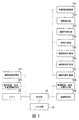
- FIG. 1 is a block diagram showing a schematic configuration of the image processing apparatus according to the first embodiment of the present invention.
- FIG. 2 is a diagram illustrating an example of an image represented by image information acquired by an image information acquisition unit included in the image processing apparatus of FIG.
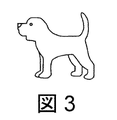
- FIG. 3 is a diagram illustrating an example of a contour line indicated by the contour information extracted by the contour extracting unit included in the image processing apparatus of FIG.
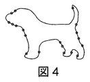
- FIG. 4 is a diagram illustrating an example of a contour line smoothed to a certain smoothing level.
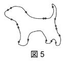
- FIG. 5 is a diagram showing an example in which the contour line shown in FIG. 4 is smoothed to a higher smoothing level.
- FIG. 6 is a diagram showing an example in which the contour line shown in FIG. 5 is smoothed to a higher smoothing level.
- FIG. 5 is a diagram showing an example in which the contour line shown in FIG. 5 is smoothed to a higher smoothing level.
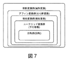
- FIG. 7 is a diagram for explaining the geometric transformation.
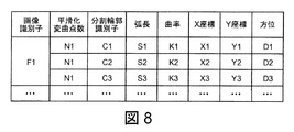
- FIG. 8 is a diagram illustrating an example of information output from the contour arc length / curvature / position output unit included in the image processing apparatus of FIG. 1.
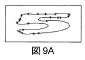
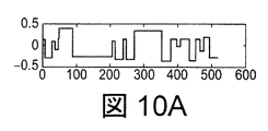
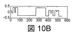
- 9A and 9B are diagrams illustrating an example of two contour lines that are targets of determination of similarity / dissimilarity in the image processing apparatus of FIG. 10A and 10B are diagrams respectively showing the results of profiling the arc length information and the curvature information obtained from the contour lines of FIGS. 9A and 9B.
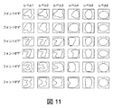
- FIG. 11 is a diagram showing an example of smoothing the contour lines of numbers of two types of fonts in a plurality of stages.
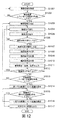
- FIG. 12 is a flowchart showing an example of the operation of the image processing apparatus of FIG. FIG.
- FIG. 13 is a block diagram showing a schematic configuration of an image processing apparatus according to the second embodiment of the present invention.
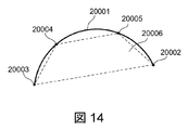
- FIG. 14 is a diagram for explaining a characteristic area in the divided contour line.
- FIG. 15 is a flowchart showing an example of the operation of the image processing apparatus of FIG.
- FIG. 16 is a block diagram showing a schematic configuration of an image processing apparatus according to the third embodiment of the present invention.
- FIG. 17 is a flowchart showing an example of the operation of the image processing apparatus of FIG.
- FIG. 1 An expression method for expressing an object or a shape according to the first embodiment of the present invention is realized by, for example, an image processing apparatus as shown in FIG. 1 includes a control unit 10, a memory 20, an input / output unit 30, an image information acquisition unit 101, a contour extraction unit 102, a contour smoothing unit 103, a contour dividing unit 104, a contour Arc length calculation unit 105, contour curvature calculation unit 106, contour position calculation unit 107, contour arc length / curvature / position output unit 108, image determination unit 109, image information storage unit 201, contour arc length / And a curvature / position information storage unit 202.
- the image information acquisition unit 101 uses the input / output unit 30 to extract image information (image data) such as a photograph designated by the user from the image information storage unit 201.
- image information acquisition unit 101 may acquire image information from an image input unit (not shown) such as a scanner.
- the image information acquisition unit 101 may perform conversion processing for facilitating subsequent processing, for example, color / monochrome conversion, when acquiring image information.
- FIG. 2 shows an example of an image represented by the image information acquired by the image information acquisition unit 101.
- the image in FIG. 2 includes only one object (dog).
- the contour extraction unit 102 extracts the contour information (contour line) of the object included in the image from the image information acquired by the image information acquisition unit 101.
- the extraction of the contour information can be performed by extracting points where the hue, saturation, brightness, etc. change abruptly using a Laplacian / Gaussian filter, for example.
- the contour information extraction method is not limited to the above method.
- the extracted contour information of the object is expressed as a collection of contour points expressed as (x, y), for example, using an orthogonal coordinate system.
- An example of the contour line indicated by the contour information extracted by the contour extracting unit 102 is shown in FIG.
- the contour smoothing unit 103 performs stepwise multi-step smoothing on the contour line extracted by the contour extracting unit 102. For this smoothing, for example, convolution using a Gaussian filter or the like can be used, but is not limited thereto.
- the smoothing is first performed for the purpose of removing the influence of noise in the subsequent processing, and then, in order to obtain a plurality of stepped (hierarchical) contour information (smoothed contour lines). Is called.
- stepped contour information smoothed contour lines
- the degree of smoothing is determined based on the number of times of smoothing and the number of “inflection points” described later. Examples of smoothing in multiple stages (hierarchical) with the number of inflection points as a guide are shown in FIGS.
- the contour dividing unit 104 functions as a dividing unit that divides the contour line of each smoothing level smoothed by the contour smoothing unit 103 into one or more partial contour lines. This division is performed using characteristic points regarding the degree of bending in the smoothed contour as division points. As a result of using such division points, the partial outline becomes a curve. If there is no division point, no division is performed. In this case, the divided outline after division matches the entire outline before division.
- the contour shape of the whole or part of the object or shape is divided into one or a plurality of curves.
- the “bending degree” is an amount defined based on the characteristics related to the curve of the curve, such as the Euclidean curvature, the Euclidean radius of curvature, and the affine curvature, and how much the curve is distorted compared to the straight line.
- the amount to describe Any of these amounts may be used as an amount that defines the degree of curve bending, but here, the Euclidean curvature is used. That is, the contour dividing unit 104 divides the contour line using the inflection point of the Euclidean curvature on the contour as a dividing point.
- the “inflection point” means a point where the sign of curvature changes on the contour line. Since the inflection point of the Euclidean curvature is invariant to the projective transformation, it is a robust point with respect to the geometric transformation. That is, by using the inflection point of the Euclidean curvature as the division point, a point that is robust to geometric transformation can be used as the division point.
- the geometric transformation will be described with reference to FIG.
- the “transformation group” is a group having each geometric transformation as an element.
- the Euclidean geometric transformation (including rotation) is transformation involving rotation and translation.
- the affine geometric transformation (including the similarity transformation) is obtained by adding the scaling / shearing transformation to the Euclidean geometric transformation.
- the projective transformation is the affine geometric transformation obtained by adding a sector transformation. Therefore, the relationship of projective transformation ⁇ affine geometric transformation ⁇ Euclidean geometric transformation is established, and projective transformation is the broadest geometric transformation among them. Since the inflection point of the Euclidean curvature is an invariant to the projective geometric transformation, it can be said that it is robust in the broadest geometric transformation. In other words, if the inflection point of the Euclidean curvature is taken as a division point, the division point is a division point that is robust to geometric transformation.
- the contour dividing unit 104 divides the contour line, it is desirable to perform a certain degree of smoothing as the preprocessing. By performing smoothing as preprocessing, the contour line can be divided without being affected by the local bending state when there is a lot of noise.
- the contour arc length calculation unit 105 calculates the arc length of each of the divided contour lines divided by the contour division unit 104.
- the arc length here may be either a Euclidean arc length or an affine arc length, but it is desirable to use the affine arc length.
- the affine arc length is an invariant with respect to the equal product affine geometric transformation (including the Euclidean geometric transformation) and is a more robust amount with respect to the geometric transformation.
- the affine arc length s is defined by the following formula (2). Where t 1 And t 2 Represents the coordinates of the start point and end point of each divided contour line. The start point and the end point are points that can be determined by the shape of the divided contour line.
- the contour curvature calculator 106 calculates the curvature of each of the divided contour lines divided by the contour divider 104.
- the curvature here may be either Euclidean curvature or affine curvature, but it is desirable to use affine curvature.
- Affine curvature ⁇ A is defined by the following equation (3). Represents second and third order derivatives, respectively.
- the curvature information calculated by the contour curvature calculation unit 106 may define curvature information for all contour points included in the divided contour line as a vector of dimensions corresponding to the number of contour points, and may also calculate an average value or a maximum value. -You may be represented by a value such as the minimum value.
- the effect of obtaining both the arc length and the curvature of the split contour is an invariant to the equal-affine affine transformation, so by taking the ratio of the two, the affine geometric transformation with scaling can be obtained. it is that it provides a invariants.
- the contour point is a point that can be determined by the shape of the divided contour line.
- Both the arc length information calculated by the contour arc length calculation unit 105 and the curvature information calculated by the contour curvature calculation unit 106 are feature quantities (parameters) that express the degree of bending of the corresponding divided contour line. , characteristic of the contour is represented by a parameter. As described above, the contour arc length calculation unit 105 and the contour curvature calculation unit 106 each function as a parameter calculation unit.
- the contour position calculation unit 107 calculates each position (also referred to as a positional relationship) of the divided contour lines divided by the contour division unit 104.
- the position here, the coordinates of the inflection points at both ends of the divided contour line may be used, or the coordinates such as the center of gravity calculated using the respective contour point coordinates forming the divided contour line may be used. .
- various coordinates such as a polar coordinate system as well as an orthogonal coordinate system can be used. When the polar coordinate system is used, not only the positional relationship including the size but also the positional relationship based on the relative angle can be expressed. Or you may employ
- the information regarding the position of the divided contour line may include not only the absolute position and the relative position of the divided contour line but also the direction in which the convex portion of the divided contour line faces.
- the azimuth can be described as the orientation of the major axis or minor axis when each point included in the divided contour is approximated by ellipse approximation or the like.
- the description method of the azimuth is not limited to the method using the ellipse approximation. For example, various methods such as a method of describing the direction perpendicular to the straight line connecting the positions of the two end points of the divided contour line are conceivable.
- the position calculation by the contour position calculation unit 107 can also be used to obtain the positional relationship between the divided contour lines related to one object. It can also be used to obtain the mutual positional relationship between a plurality of contour lines included in one image. By looking at the positional relationship between a plurality of contour lines, it is possible to recognize the object more accurately, and it is possible to recognize the object even when the contour line represents a part of the object. Furthermore, it is also effective when a plurality of contour lines are extracted for one object.
- the contour arc length / curvature / position output unit 108 outputs the arc length information, the curvature information, and the position information calculated by the contour arc length calculation unit 105, the contour curvature calculation unit 106, and the contour position calculation unit 107, respectively. Is output to the contour arc length / curvature / position information storage unit 202 as information representing the feature amount of the image.
- An example of information output from the contour arc length / curvature / position output unit 108 is shown in FIG. In FIG. 8, the contour line to which the image identifier F1 is assigned has an inflection point of N1 by smoothing and is divided into three divided contour lines C1 to C3.
- the divided contour C1 has an arc length S1, a curvature K1, an X coordinate X1, a Y coordinate Y1, and an orientation D1.
- the image determination unit 109 determines matching or similarity between two objects (images) based on information (feature amount) stored in the contour arc length / curvature / position information storage unit 202. This determination can be used to search for an object that is most similar to one object. Further, in order to classify one object into any of a plurality of groups, it can be used for comparison with an object representing each group.
- the image determination unit retrieves the information on the one object and the information on the comparison object different from the information from the contour arc length / curvature / position information storage unit 202 and compares them, and matches / mismatches (similarity). / Dissimilar).
- the determination by the image determination unit 109 is performed by comparing all or part of information on the arc length, curvature, position, and orientation with each other. When the value indicated by each information or the difference (parameter distance) between the values obtained from the information is below a predetermined threshold value, it is determined as “match (similar)”, otherwise “match (similar)” “No”.
- FIG. 10B a method for determining similarity / dissimilarity between two contour lines will be specifically described.
- two contour lines representing the number “5” of different fonts are illustrated as the two contour lines.
- FIG. 9A and FIG. 9B show the contour line of the number “5” in different fonts and the inflection points on the contour line.
- Each of these contour lines is divided into a plurality of divided contour lines, and arc length information and curvature information are obtained from each of the divided contour lines. Then, the obtained arc length information and curvature information are profiled to obtain profiles as shown in FIGS. 10A and 10B, respectively.
- the horizontal axis represents the length obtained by accumulating the arc lengths of the divided contour lines
- the vertical axis represents the curvature corresponding to each divided contour line.
- each of the two contour lines to be determined represents the entire object, but at least one of the two contour lines to be determined is a single object. Even if it represents a part, it can be determined.
- the contour dividing unit 104 divides the contour line into one or more partial contour lines, and obtains information on the arc length, curvature, position, and orientation for each partial contour line. is there. Therefore, according to the present embodiment, it is possible to make a determination on a shielded object or shape.
- the similarity / dissimilarity determination is performed using the arc length information and the curvature information for all of the plurality of divided contour lines has been described.
- Similarity / dissimilarity determination may be performed using arc length information and curvature information.
- a predetermined number of divided contour lines are selected in order from the longest arc length, and the difference in curvature between the divided contour lines in the same order is obtained.
- the obtained curvature difference is weighted according to the order of the arc lengths, and the weighted curvature differences are summed. Based on the total obtained in this way, the similarity between the two contour lines is determined. According to this method, since it is not necessary to use all the information, the amount of calculation can be reduced and high-speed processing becomes possible.
- the above-described determination is performed for each smoothing level.
- the contour lines of each object are smoothed to a plurality of smoothing levels, and feature amounts are obtained for the smoothing contour lines of each smoothing level.
- the degree of similarity of the shape of the article is obtained by comparing feature quantities for each level from the highest level to the lowest level.
- all the figures (contour lines) converge to convex figures.
- the degree of similarity between the shapes of two objects can be expressed depending on at which smoothing level it is determined as “match (similar)”. For example, the outline of the same object is determined as “match (similar)” at all smoothing levels.
- FIG. 11 shows an example in which the numbers “4”, “7”, and “3” of the two types of fonts A and B are each smoothed to multi-levels. There are 6 smoothing levels, and the smoothing level increases from the left side to the right side of the figure.
- the similar / dissimilar determination result of each number may differ depending on the feature amount used, a set threshold value, and the like.
- the determination result is as follows. At smoothing levels 5 and 6 (first and second columns from the right in the figure), all numbers are determined to be “similar”. At the smoothing level 4 (third column from the right in the figure), the numbers “4” and the numbers “7” and “3” are determined to be “dissimilar”. At the smoothing level 3 (third column from the left in the figure), the number “7” and the number “3” are determined to be “dissimilar”.
- the number “4” of font A and the number “4” of font B, the number “3” of font A and the number “3” of font B are respectively It is determined to be "non-similar".
- the similarity is expressed by smoothing levels 1 to 6
- the similarity between the number “7” of font A and the number “7” of font B is “1”
- the number “4” of font A is “4”.
- the similarity between the number “4” of the font B, the number “3” of the font A, and the number “3” of the font B is “2”, respectively.
- the similarity between the numbers “7” and “3” is “4”, and the similarity between the numbers “4” and “7” or “3” is “5”.
- the image determination unit 109 performs similarity / dissimilarity between two contour lines for each smoothing level, thereby obtaining a similarity indicating how similar the contour lines are. it can.
- the similarity determination by the image determination unit 109 is not necessarily performed using smoothing. For example, this can be substituted by a method of comparing a multi-step from a partial contour having a long arc length or a partial contour peculiar to a certain figure.
- the image information acquisition unit 101 of the image processing apparatus acquires image information designated by the user (step S1001). Acquisition of image information is not limited to user designation, and may be automatically acquired. For example, an image from the imaging unit is acquired according to a detection result of a sensor or the like. Next, it is confirmed whether or not all designated image information has been acquired (step S1002). If acquisition of all designated image information has not been completed (NO in step S1002), steps S1001 and S1002 are repeated until all designated image information is obtained. When all the designated image information is acquired (YES in step S1002), the image information acquisition unit 101 sends the acquired image information to the contour extraction unit 102.
- the contour extraction unit 102 extracts the contour information included in the image based on the image information sent from the image information acquisition unit 101 (step S1003).
- the extraction of the contour information can be performed only for those that satisfy a predetermined standard set in advance by the user, such as a contour line having a length equal to or longer than a threshold.
- the contour information extracted by the contour extraction unit 102 is sent to the contour smoothing unit 103.
- the contour smoothing unit 103 smooths the contour line based on the contour information from the contour extracting unit 102 (step S1004).
- the number of inflection points is detected (step S1005), and it is determined whether or not the number of inflection points has decreased to a preset number (corresponding to a certain smoothing stage) (step S1006).
- the smoothing is repeated until the number of inflection points matches (decreases) a preset number.
- the preset number used in step S1006 is set to a different value depending on the smoothing level.
- the contour dividing unit 104 divides the contour line smoothed in a certain stage into one or more divided contour lines (step S1007). This division is performed using a characteristic point regarding the degree of curve of the smoothed contour as a division point. For each of the divided contour lines divided by the contour dividing unit 104, the contour arc length calculation unit 105 calculates the arc length (step S1008), and the contour curvature calculation unit 106 calculates the curvature (step S1009).
- the position calculation unit 107 calculates a position (step S1010).
- the contour arc length / curvature / position output unit 108 outputs and stores the arc length / curvature / position information calculated in steps S1005 to S1007 to the contour arc length / curvature / position information storage unit 202 (step S1011).
- the contour smoothing unit 103 determines whether or not the number of inflection points is zero or less than a predetermined number (step S1012). That is, it is determined whether or not smoothed contour lines have been obtained for all of the plurality of stages. If smoothing contour lines of all smoothing levels are not obtained, the process returns to step S1004 and the subsequent processing is repeated.
- the contour extraction unit 102 determines whether all the contour lines included in the image information from the image information acquisition unit 101 have been extracted (step S1013). This is a process for a case where there are a plurality of contour lines, particularly when one object has a plurality of contour lines (a case where a plurality of parts are included). If there is an outline that has not been extracted, steps S1003 to S1013 are repeated. If YES is determined in step S ⁇ b> 1013, the image determination unit 109 determines that an image is mutually correlated with one or more other images based on information stored in the contour arc length / curvature / position information storage unit 202. a determination whether similar. This determination is performed for each smoothing level.
- step S1014 information obtained from contour lines having the lowest smoothing level (at the highest level) is compared. If there is matching (or similar) information (YES in step S1015), the search image corresponding to the information is output as a similar image (step S1017). If there is no matching (or similar) information (NO in step S1015), the information obtained from the contour line (in the next lower layer) with the one-step smoothing level increased is compared (step S1016).
- step S1015 If there is matching (or similar) information (YES in step S1015), the search image corresponding to the information is output as a similar image (step S1017). If there is no matching (or similar) information (NO in step S1015), the information obtained from the contour line with a further increased smoothing level is compared. Thereafter, steps S1015 to S1016 are repeated until it is determined that there is matching (or similar) information or until the determination for the highest degree of smoothing level is completed. Although the case where the most similar image is output has been described here, the search result may be output as the similarity.
- each of a plurality of smoothed contour lines smoothed in a plurality of stages is divided into one or more curves, and each of the divided curves is bent and positioned. It is possible to appropriately evaluate the degree of similarity between two images by expressing with the parameters included and comparing the parameters (features) for each smoothing level.
- each of the plurality of divided contour lines is represented as a parameter (determining a feature value for each divided contour line), it is possible to perform image recognition that is robust against occlusion.
- FIG. 13 is a block diagram showing a configuration of an image processing apparatus used for realizing an expression method for expressing an object or a shape according to the second embodiment of the present invention.
- 1 differs from the image processing apparatus of FIG. 1 in that a contour occupation area calculation unit 111 is used instead of the contour curvature calculation unit 106, and a contour arc length / occupation area / position output unit is used instead of the contour arc length / curvature / position output unit 108. 112 is that each have.
- the contour occupation area calculation unit 111 calculates a characteristic area (also referred to as a contour occupation area) for each of the divided contour lines divided by the contour division unit 104.
- the affine curvature used in the first embodiment has a large variation in value and is difficult to handle.
- the contour occupation area has a limited fluctuation range and is easy to handle, and the object or the shape can be easily recognized.
- the characteristic area is, for example, an area determined depending on each divided contour line 20001 as shown in FIG. That is, the area is calculated using points that can be determined by the shape of each divided contour line. More specifically, there are four points 20004 and 20005 that equally divide the two end points 20002 and 20003 of the divided contour 20001 from the contour arc length expressed by the affine arc length of the divided contour 20001 (here, three equal parts).
- the area of the quadrangle connecting the two can be a characteristic area.
- the area of the region surrounded by the straight line connecting the two end points 20002 and 20003 of the divided contour 20001 and the divided contour 20001 can also be a characteristic area. However, it is preferable to use the area of the region surrounded by the four points 20002 to 20005.
- the area surrounded by these four points is the equal product This is because it becomes an invariant with respect to the affine transformation and a robust amount with respect to the geometric transformation.
- segmentation number of the contour arc length expressed by the affine arc length should just be 2 or more (2 or more equal parts).
- the contour occupation area calculation unit 111 obtains the area of the triangle connecting the two end points 20002 and 20003 of the division contour line 20001 and one division point as the contour occupation area.
- the contour arc length / occupied area / position output unit 112 outputs the arc length information / occupied area information / position information calculated by the contour arc length calculator 105, the contour occupied area calculator 111, and the contour position calculator 107 respectively.
- the contour position calculation unit 107 may calculate the contour position by a method similar to the method of deriving the occupied area by the contour occupied area calculation unit 111. By adopting this method, the positional relationship can be described invariably with respect to the affine geometric transformation. Further, an invariant calculated from the positional relationship may be added to the feature amount.
- the invariant calculated from the positional relationship is, for example, an area surrounded by four representative points extracted from each division point (inflection point) calculated by the contour division unit 104. .
- This quantity provides an invariant for the equal product affine geometric transformation.
- an invariant with respect to the affine geometric transformation with scaling can be obtained.
- step S1011 is also changed to step S1102 in which the contour arc length / occupied area / position output unit 112 outputs the arc length / occupied area / position information calculated in steps S1008, S1101 and S1010.
- the obtained feature amount is easy to handle and the object or the shape can be easily recognized. be able to.
- 16 is a block diagram showing a configuration of an image processing apparatus used for realizing an expression method for expressing an object or a shape according to the third embodiment of the present invention.
- 1 is different from the image processing apparatus of FIG. 1 in that an inflection point extraction unit 121, a contour orientation calculation unit 122, and a coordinate conversion unit 124 are newly added, and the contour arc length / curvature / position output unit 108 is replaced with a contour arc.
- the long / curvature / position / azimuth output unit 123 is provided. Further, even if the names are the same, there are elements having functions different from those of the image processing apparatus of FIG. Hereinafter, differences from the image processing apparatus of FIG. 1 will be described.
- the inflection point extraction unit 121 extracts an inflection point on the contour in the same manner as the contour division unit 104 in the first embodiment.
- the contour dividing unit 104 further divides the region between the inflection points (referred to as a contour segment) unlike the method of using the inflection points as the contour dividing points in the contour dividing unit 104 in the first embodiment ( Contour subsegment).
- a method of dividing the contour segment for example, the number of contour sub-segments in one contour segment is made equal, and the contour sub-segments in one contour segment are divided so that the arc lengths are equal.
- the method for generating the contour sub-segment is not limited to this method, and any method may be used.
- the apparatus after the contour arc length calculation part 105 shall process with respect to each of the said contour subsegment.
- the contour orientation calculation unit 122 is a processing unit newly added to the first embodiment.
- the contour position calculation unit 107 may calculate the orientation.
- the contour orientation calculation unit 122 performs this. Accordingly, the contour position calculation unit 107 calculates a position different from the orientation information. For example, the position can be calculated so as to specify a two-dimensional position in the image using an orthogonal coordinate system.
- the contour arc length / curvature / position output unit 108 outputs a contour arc length / curvature / position / azimuth output in addition to the contour arc length / curvature / position information.
- the contour arc length / curvature / position information storage unit 202 is changed to a contour arc length / curvature / position / orientation information storage unit 204.
- the coordinate conversion unit 124 appropriately converts the coordinates of the image acquired by the image information acquisition unit 101 so as to correspond to each of the images included in the image information storage unit 201.
- the coordinate conversion unit 124 also performs coordinate conversion on the contour arc length / curvature / position / orientation information output from the contour arc length / curvature / position / orientation output unit 123.
- the contour arc length / curvature / position / azimuth information output for the image acquired by the image information acquisition unit 101 is the contour arc length / curvature / correspondence corresponding to each image included in the image information storage unit 201. This is performed so as to approximate the position / orientation information most closely.
- the coordinate transformation for example, linear transformation such as translation, rotation, enlargement / reduction, affine geometric transformation, projective geometric transformation in a two-dimensional orthogonal coordinate system can be used.
- the conversion means used for the coordinate conversion may be any conversion means regardless of linear conversion or non-linear conversion.
- the operation of the image processing apparatus shown in FIG. 16 will be described with reference to FIG. The difference from FIG. 12 is that the contour orientation calculation unit 122 calculates the contour orientation after step S1010 (S1201). Accordingly, step S1011 is also changed to step S1202 in which the contour arc length / curvature / position / orientation output unit 123 outputs the arc length / curvature / position / orientation information calculated in steps S1008, S1009, S1010, and S1201. Has been. Furthermore, in FIG. 17, the partial outlines divided in step S1007 correspond to the sub-segments.
- the search for an image in step S1014 involves coordinate conversion processing in the coordinate conversion unit 124.
- the following effects can be expected in addition to the effects of the first embodiment by dividing the contour in two stages of segments and sub-segments and using coordinate transformation.
- the segment contributes to searching for corresponding points of two images at high speed.
- the sub-segment can then describe in detail the local contour features within the segment (between the inflection points).
- coordinate transformation contributes to robust image recognition regardless of image distortion.
- the combination of the contour arc length calculation unit 105 and the contour curvature calculation unit 106 or the contour occupation area calculation unit 111 is illustrated, but instead of these combinations, the contour curvature calculation unit 106 and the contour occupation area combination of the calculator 111 can also be used. Further, the contour orientation calculation unit 122 may be combined. In these cases, other related components are appropriately changed according to the combination.
- an image processing apparatus that specializes in image processing has been described. However, an ordinary computer (computer) may be caused to operate as an image processing apparatus by executing a program that performs the above processing. Good. That is, the present invention can be provided as a program that causes a computer to execute the above-described image processing method.
- the computer may be provided as a computer-readable non-temporary information recording medium in which the program is recorded.
- the computer when the computer is operated as the image processing apparatus of FIG. 1 using a normal computer, the computer may have at least the control unit 10, the memory 20, and the input / output unit 30.
- the memory 20 stores the program and also serves as the image information storage unit 201 and the contour arc length / curvature / position information storage unit 202.
- the control unit 10 also serves as the image information acquisition unit 101 to the image determination unit 109 by executing the program. If necessary, a reading device is provided that reads a program from an information recording medium and sends the read program to the memory 20 or the like.
- the step of obtaining the feature amount includes dividing each of the plurality of stages of smoothed contour lines into one or more partial contour lines, and obtaining a feature amount for each of the divided contour lines.
- the image processing method according to supplementary note 1. (Supplementary note 3) The image processing method according to supplementary note 2, wherein the feature amount includes information on a position and a bending state of each partial outline. (Supplementary Note 4) The information on the degree of bending is an area of a region surrounded by a plurality of points existing on the partial contour line or a straight line connecting a plurality of points determined depending on the shape of the partial contour line.
- the information regarding the said bending condition is the area of the area
- the said partial outline The image processing method according to supplementary note 3, which is a combination of any two or more of a line arc length and a curvature of the partial outline.
- the image processing method according to supplementary note 5 wherein the information related to the curve state of the curve is represented by two of an arc length and a curvature of the curve.
- the method of dividing into partial contour lines is to divide globally based on inflection points where the sign of curvature on the contour lines changes, and to further locally localize the regions between the inflection points.
- the said area is an area of the area
- the present invention in recognition of an object in a general image or moving image, it can be applied to uses such as searching for a desired image and classifying an image. In particular, it can be applied to uses such as retrieval and classification of similar but different images.
- This application claims priority based on Japanese Patent Application No. 2010-263877 filed on November 26, 2010 and Japanese Patent Application No. 2011-213005 filed on September 28, 2011. , The entire disclosure of which is incorporated herein.
Landscapes
- Engineering & Computer Science (AREA)
- Computer Vision & Pattern Recognition (AREA)
- Physics & Mathematics (AREA)
- General Physics & Mathematics (AREA)
- Multimedia (AREA)
- Theoretical Computer Science (AREA)
- Image Analysis (AREA)
Abstract
Description
物体認識に関する技術として、顔認識や指紋認識など様々な認識技術がこれまでに開発されてきたが、これらはすべて特定の用途に向けられたものである。このようなある一つの用途に特化した認識技術は、別の用途に利用しようとすると、途端に認識率が下がるなどの問題がある。このため、一般的な物体の認識を行う技術の開発が期待されている。
一般物体の認識を行うには、認識対象となる画像の特徴量を抽出することが必要となる。この特徴量を抽出する方法として、特許文献1や特許文献2に示される、画像に含まれる幾何学的特徴を用いる方法が、広く知られている。しかしながら、こうした特徴量のほとんどは、統計的学習やユーザーの経験によって、閾値などのパラメータを前もって設定しておかなければ計算できないものである。統計的学習やユーザーの経験を必要とする方法は、これまで学習が行われなかった画像に対して特徴量を計算することができず、誤った認識結果を与えるという問題がある。
統計的学習やユーザーの経験を必要とせずに特徴量を計算する方法として、非特許文献1に示される、画像の局所的な強度勾配を集積したヒストグラムを用いたSIFT(Scale Invariant Feature Transform)という手法が広く認知されている。本技術を利用することによって、幾何変換や遮蔽を伴う同一画像を、同一であると認識することが可能である。しかしながら、本技術は二つの画像が同一であるか否かを判断するためのものであり、類似する二つの画像に対して、どの程度似ているのかについての情報を与えることができない。
また、非特許文献2に示される、画像輪郭を段階的に平滑化し、それぞれでの輪郭の変曲点の位置を用いて表現したCSS(Curvature Scale Space)という表現方法を用いた認識もまた、よく知られている。本技術で用いられている変曲点の位置情報は、同一画像或いは類似する画像において、よく似た出現パターンを持つということが知られている。従って、本技術を用いることによって、輪郭が同一の或いは類似する画像の認識、または、それらの幾何変換が施された画像を、同一である、或いは類似すると認識することが可能である。しかしながら、本技術は、変曲点以外の点の情報を全く利用せず、輪郭に関する情報の中の非常に限られた情報のみを用いる。それゆえ、輪郭が相互に類似する画像であっても、変曲点の位置情報が異なると「類似しない」と判定することがある。また、輪郭が相互に類似しない画像であっても、変曲点の位置情報が比較的類似していると、「類似する」と判定したりすることがある。すなわち、本技術は、類似度を輪郭の特徴によって算出することができていないと言える。
一方で、輪郭上の各点の曲率情報を用いて認識を行う手法もまた提案されている(特許文献3)。本技術は、輪郭上の点すべての曲率情報を用いており、輪郭形状が若干異なる輪郭に対しても、類似度を算出することが可能である。しかしながら、本技術は、形状の外形一周分の輪郭を比較することを前提にしている。このため、輪郭が途中で切れていたり、画像中の物体形状の一部が他の物体形状と重なっている場合には、本技術を用いることができない。
そこで、本発明の目的は、異なる二つの画像に対してどの程度にているのかを示す類似度を求めることができ、幾何変換や遮蔽による画像改変に対してロバストな物体認識を可能にする物体または形状の情報表現方法を提供することにある。
本発明の一形態は、物体または形状を表現するための情報表現方法であって、前記物体または形状の全体または一部の輪郭形状をひとつまたは複数の曲線に分割し、前記輪郭形状を、前記分割された各曲線の曲がり具合と位置関係とを含むパラメータで表現することを特徴とする。
本発明の一形態による効果は、統計的学習やユーザーの経験を必要とすることなく、一般的な物体の認識を行う手法を提供することにある。特に、手書き文字などの、似ているけれども細部が異なる形状や、背景情報から全輪郭を取り出すことが困難な物体形状や、形状の一部が隠蔽されるなどの事情によって欠けているために全輪郭を取り出すことが困難な物体形状や、形状内が不連続であることから全輪郭を取り出すことが困難な物体形状など、一般的に存在する形状に対してロバストな認識を行う手法を提供することにある。
図2は、図1の画像処理装置に含まれる画像情報取得部によって取得される画像情報が表す画像の一例を示す図である。
図3は、図1の画像処理装置に含まれる輪郭抽出部によって抽出された輪郭情報が示す輪郭線の一例を示す図である。
図4は、ある平滑化レベルに平滑化された輪郭線の一例を示す図である。
図5は、図4に示す輪郭線をさらに高い平滑化レベルまで平滑化した例を示す図である。
図6は、図5に示す輪郭線をさらに高い平滑化レベルまで平滑化した例を示す図である。
図7は、幾何変換について説明するための図である。
図8は、図1の画像処理装置に含まれる輪郭弧長・曲率・位置出力部より出力される情報の一例を示す図である。
図9A及び図9Bは、図1の画像処理装置において、類似/非類似の判定の対象となる2つの輪郭線の一例を示す図である。
図10A及び図10Bは、図9A及び図9Bの輪郭線から得た弧長情報と曲率情報とをプロファイル化した結果をそれぞれ示す図である。
図11は、2種類のフォントの数字の輪郭線を複数段階に平滑化した例を示す図である。
図12は、図1の画像処理装置の動作の一例を示すフローチャートである。
図13は、本発明の第2の実施の形態に係る画像処理装置の概略構成を示すブロック図である。
図14は、分割輪郭線における特徴的な面積を説明するための図である。
図15は、図13の画像処理装置の動作の一例を示すフローチャートである。
図16は、本発明の第3の実施の形態に係る画像処理装置の概略構成を示すブロック図である。
図17は、図16の画像処理装置の動作の一例を示すフローチャートである。
本発明の第1の実施の形態に係る物体または形状を表現するための表現方法は、例えば、図1に示すような画像処理装置によって実現される。
図1の画像処理装置は、制御部10と、メモリ20と、入出力部30と、画像情報取得部101と、輪郭抽出部102と、輪郭平滑化部103と、輪郭分割部104と、輪郭弧長計算部105と、輪郭曲率計算部106と、輪郭位置計算部107と、輪郭弧長・曲率・位置出力部108と、画像判定部109と、画像情報記憶部201と、輪郭弧長・曲率・位置情報記憶部202とを有している。
画像情報取得部101は、入出力部30を用いてユーザーが指定する写真などの画像情報(画像データ)を、画像情報記憶部201から取り出す。或いは、画像情報取得部101は、図示しない画像入力部、例えばスキャナ等、から画像情報を入手してもよい。画像情報取得部101は、画像情報を取得する際にその後の処理を容易にするための変換処理、例えば、カラー・白黒変換を行ってもよい。図2に、画像情報取得部101によって取得される画像情報が表す画像の一例を示す。図2の画像には、物体(犬)が一つだけ含まれている。
輪郭抽出部102は、画像情報取得部101によって取得された画像情報から画像中に含まれる物体の輪郭情報(輪郭線)を抽出する。輪郭情報の抽出は、例えば、ラプラシアン・ガウシアンフィルタなどを用いて、色相・彩度・明度などが急激に変化する点を抽出することにより行うことができる。もちろん、輪郭情報抽出方法は、上記方法に限られるものではない。抽出された物体の輪郭情報は、例えば、直交座標系を用いて(x,y)などのように表現される輪郭点の集まりとして表現される。輪郭抽出部102によって抽出された輪郭情報が示す輪郭線の一例を図3に示す。
輪郭平滑化部103は、輪郭抽出部102によって抽出された輪郭線に対して段階的な多段階の平滑化を行う。この平滑化には、例えばガウシアンフィルタによる畳み込みなどを利用することができるが、それに限られない。平滑化は、まず、後の処理におけるノイズの影響を除去することを目的として行われ、続いて、段階的な(階層化された)複数の輪郭情報(平滑化輪郭線)を得るために行われる。後述するように、複数の段階的な輪郭情報のそれぞれについて、他の画像中の物体に関して求めた段階的な輪郭情報との類似度を求めることで、物品の形状の類似度をより高い精度で求めることができる。平滑化の度合い(平滑化レベル)は、平滑化回数や、後述する「変曲点」の数に基づいて決定する。変曲点の数を目安に多段階(階層的)に平滑化を行った例を図4から図6に示す。「変曲点」の数は、平滑化を繰り返すことにより減少し、やがてゼロに収束する(あらゆる閉曲面の輪郭は平滑化レベルがある程度以上になると凸図形となる)。
なお、この平滑化は、階層化を平滑化で行う場合は必要だが、その他の手法で階層化を行う場合は必ずしも行う必要はない。
輪郭分割部104は、輪郭平滑化部103により平滑化された各平滑化レベルの輪郭線を1つ以上の部分輪郭線に分割する分割手段として機能する。この分割は、平滑化輪郭線における曲がり具合に関して特徴的な点を分割点として行う。このような分割点を利用する結果、部分輪郭線は曲線となる。分割点が存在しない場合には、分割は行わない。この場合、分割後の分割輪郭線は、分割前の輪郭線全体に一致する。こうして、物体または形状の全体又は一部の輪郭形状はひとつまたは複数の曲線に分割される。
ここで、「曲がり具合」とは、ユークリッド曲率、ユークリッド曲率半径、アフィン曲率など、曲線の曲がりに関する特徴に基づいて定義される量であり、曲線が、直線に比較してどの程度歪んでいるかを記述する量である。これらの量のうち、どれを曲線の曲がり具合を定義する量として利用してもよいが、ここでは、ユークリッド曲率を利用するものとする。即ち、輪郭分割部104は、輪郭上のユークリッド曲率の変曲点を分割点として、輪郭線を分割する。
また、「変曲点」とは、輪郭線上で曲率の符号が変化する点を意味する。ユークリッド曲率の変曲点は、射影変換に対して不変であることから、幾何変換に対してロバストな点である。つまり、ユークリッド曲率の変曲点を分割点とすることにより、幾何変換に対してロバストな点を分割点とすることができる。
ここで、図7を参照して、幾何変換について説明する。図7において、「変換群」とは、各幾何変換を要素に持つ群である。図7から理解されるように、ユークリッド幾何変換(回転を内包)とは、回転・平行移動を伴う変換である。また、アフィン幾何変換(相似変換を内包)とは、ユークリッド幾何変換に拡大縮小・せん断変換を加えたものである。さらに、射影変換とは、アフィン幾何変換に扇形変換を加えたものである。したがって、射影変換⊃アフィン幾何変換⊃ユークリッド幾何変換、の関係が成立しており、射影変換はこの中で最も広義の幾何変換である。ユークリッド曲率の変曲点は、射影幾何変換に対しての不変量であるため、最も広義の幾何変換においてロバストであるということができる。つまり、ユークリッド曲率の変曲点を分割点とすれば、その分割点は、幾何変換に対してロバストな分割点である。
次に、ユークリッド曲率の変曲点を分割点とする輪郭線の分割方法について説明する。
まず、任意の一点を始点として輪郭線を一周するように輪郭点の座標tを取る。各輪郭点において、以下の数式(1)で定義されるユークリッド曲率κ(t)を計算し、ユークリッド曲率の値がゼロとなる点を輪郭の分割点として抽出する。


上記では、ユークリッド曲率の変曲点を用いた輪郭線の分割方法を示したが、輪郭の分割方法はこれに限らない。
輪郭弧長計算部105は、輪郭分割部104によって分割された分割輪郭線の各々の弧長を計算する。ここでの弧長は、ユークリッド弧長、アフィン弧長の何れであってもよいが、アフィン弧長を利用することが望ましい。アフィン弧長は、等積アフィン幾何変換(ユークリッド幾何変換を含む)に対しての不変量であり、幾何変換に対してよりロバストな量であるからである。アフィン弧長sは、以下の数式(2)によって定義される。

輪郭曲率計算部106は、輪郭分割部104によって分割された分割輪郭線の各々の曲率を計算する。ここでの曲率は、ユークリッド曲率、アフィン曲率の何れであってもよいが、アフィン曲率を利用することが望ましい。アフィン曲率は等積のユークリッド幾何変換を含む等積アフィン幾何変換に対しての不変量であり、幾何変換に対してよりロバストな量であるからである。アフィン曲率κAは、以下の数式(3)によって定義される。

輪郭曲率計算部106によって計算される曲率情報は、分割輪郭線に含まれるすべての輪郭点についての曲率情報を、輪郭点数分の次元のベクトルとして定義してもよく、また、平均値や最大値・最小値などの値で代表させてもよい。分割輪郭線の弧長と曲率の両者を求める効果は、これらは共に等積アフィン変換に対しての不変量であるため、両者の比を取ることで、拡大縮小を伴うアフィン幾何変換に対しての不変量を提供できることである。なお、輪郭点は、分割輪郭線の形状によって決定できる点である。
輪郭弧長計算部105によって計算される弧長情報および輪郭曲率計算部106によって計算される曲率情報は、ともに、該当する分割輪郭線の曲がり具合を表現する特徴量(パラメータ)であり、これによって、輪郭の特徴がパラメータにより表現される。このように輪郭弧長計算部105及び輪郭曲率計算部106はそれぞれパラメータ算出手段として機能する。
輪郭位置計算部107は、輪郭分割部104によって分割された分割輪郭線の各々の位置(位置関係ともいう)を計算する。ここでの位置は、分割輪郭線の両端にある変曲点の座標を用いてもよく、また、分割輪郭線をなす各輪郭点座標を用いて計算される重心などの座標を用いてもよい。座標としては、直交座標系だけでなく、極座標系など様々な座標を用いることが可能である。極座標系を用いると、大きさを含む位置関係だけでなく、相対的な角度による位置関係を表現することも可能となる。
或いは、輪郭線に沿って時計回り又は反時計回りに順番に割り当てた番号を、位置に関する情報として採用してもよい。
さらに、分割輪郭線の位置に関する情報として、分割輪郭線の絶対的な位置や相対的な位置だけでなく、分割輪郭線の凸部が向く方位を含めてもよい。方位は、分割輪郭線に含まれる各点を楕円近似などで近似した際の長軸や短軸の向きとして記述できる。方位の記述方法は、楕円近似による方法に限定されることはなく、例えば、分割輪郭線の二つの端点の位置を結ぶ直線に垂直な向きとして記述する方法など、様々な手法が考えられる。また、こうして方位を定める手法以外にも、(全体の輪郭線に関して)単純な凹凸で記述する手法も考えられる。
輪郭位置計算部107による位置計算は、一の物体に関する分割輪郭線相互の位置関係を求めるためにも利用できる。また、一の画像に含まれる複数の輪郭線の相互位置関係を求めるためにも利用できる。複数の輪郭線の位置関係を見ることで、より正確な物体の認識が可能になり、また、輪郭線が物体の一部分を表している場合でもその物体を認識することが可能になる。さらに、一の物体について複数の輪郭線が抽出されるような場合にも有効である。
輪郭弧長・曲率・位置出力部108は、輪郭弧長計算部105、輪郭曲率計算部106及び輪郭位置計算部107によってそれぞれ計算された弧長情報、曲率情報及び位置情報を、各分割輪郭線の特徴量を表す情報として輪郭弧長・曲率・位置情報記憶部202に出力する。輪郭弧長・曲率・位置出力部108より出力される情報の一例を図8に示す。
図8において、画像識別子F1が付与された輪郭線は、平滑化によって変曲点数がN1となったものであり、3つの分割輪郭線C1~C3に分割されている。分割輪郭線C1は、弧長S1、曲率K1、X座標X1、Y座標Y1及び方位D1を有している。分割輪郭線C2及びC3についても同様である。
画像判定部109は、輪郭弧長・曲率・位置情報記憶部202に格納されている情報(特徴量)に基づいて、2つの物体(画像)間の一致又は類似を判定する。この判定は、一の物体に最も類似する物体を検索するために利用することができる。また、一の物体を複数のグループのいずれかに分類するために、各グループを代表する物体と比較するために利用することができる。いずれにしても、画像判定部は、一の物体に関する情報と、それとは異なる比較用物体の情報とを、輪郭弧長・曲率・位置情報記憶部202から取り出して比較し、一致/不一致(類似/非類似)を判定する。
画像判定部109による判定は、弧長、曲率、位置及び方位に関する情報の全部又は一部を互いに比較することにより行われる。各情報が示す値又はそれら情報から求められた値の差(パラメータの距離)が予め定めた閾値を下回る場合に、「一致(類似)する」と判定し、そうでなければ「一致(類似)しない」と判定する。
図9A,図9B,図10A及び図10Bを参照して、2つの輪郭線の類似/非類似を判定する方法について具体的に説明する。ここでは2つの輪郭線として、互いに異なるフォントの数字“5”を表す2つの輪郭線を例示する。
図9A及び図9Bは、互いに異なるフォントの数字“5”の輪郭線と、その輪郭線上の変曲点を示している。これらの輪郭線をそれぞれ複数の分割輪郭線に分割し、各分割輪郭線から弧長情報と曲率情報を得る。そして、得られた弧長情報と曲率情報をプロファイル化し、図10A及び図10Bにそれぞれ示すようなプロファイルを得る。図10A及び図10Bにおいて、横軸は分割輪郭線の弧長を累積した長さ、縦軸は各分割輪郭線に対応する曲率である。
以上のようにして得られた2つの輪郭線についてのプロファイルの差を求める。その差は、例えば、弧長の累積した長さが互いに等しいときの曲率の差を、全弧長の累積した長さについて求めて合計した結果として得ることができる。こうして得られた差を、予め設定した閾値と比較することにより、2つの輪郭線の類似/非類似を判定する。
なお、上記例では、判定の対象となる2つの輪郭線がそれぞれ一つの物体の全体を表わしている場合について説明したが、判定の対象となる2つの輪郭線の少なくとも一方が、一つの物体の一部分を表している場合であっても、判定は可能である。これは、本実施の形態では、輪郭分割部104によって輪郭線を1以上の部分輪郭線に分割し、その部分輪郭線それぞれについて、弧長・曲率・位置及び方位に関する情報を求めるようにしたためである。したがって、本実施に形態によれば、遮蔽された物体または形状についても判定を行うことが可能である。
また、上記例では、複数の分割輪郭線の全てについての弧長情報と曲率情報を用いて類似/非類似の判定を行う例について説明したが、複数の分割輪郭線のうちの一部についての弧長情報と曲率情報とを用いて類似/非類似の判定を行うようにしてもよい。その場合、例えば、比較する2つの輪郭線に関して、弧長の長いものから順番に所定数の分割輪郭線を選択し、同一順番の分割輪郭線の曲率の差を求める。そして、求めた曲率の差に、弧長の長さの順番に応じた重み付けを行い、重み付けされた曲率の差を合計する。こうして得られた合計に基づいて、2つの輪郭線の類似/非類似の判定を行う。この方法によれば、全ての情報を用いる必要がないので、計算量を低減でき、高速処理が可能になる。
上述した判定は、平滑化レベルごとに行われる。上述したように、各物体の輪郭線は、複数平滑化レベルに平滑化されており、各平滑化レベルの平滑化輪郭線についてそれぞれ特徴量が求められる。平滑化レベルの最も高いものから最も低いものまで、各レベル毎に特徴量を比較することにより物品の形状の類似度を求める。
平滑化レベルが高くなると、全ての図形(輪郭線)は凸図形に収束する。このため、平滑化レベルが高くなるに従い、2つの物体の形状は「一致(類似)する」と判定される可能性が高くなる。したがって、どの平滑化レベルで「一致(類似)する」と判定されたかによって、2つの物体の形状の類似度を表すことができる。例えば、同一の物体の輪郭線は、全ての平滑化レベルで「一致(類似)する」と判定される。また、よく似た物体の輪郭線は、平滑化レベルが比較的低い段階から「一致(類似)する」と判定される。また、ある程度似ている物体の形状は、平滑化レベルが高くなると「一致(類似)する」と判定される。そして、全く似ていない物体の形状は、平滑化レベルが高くなっても「一致(類似)しない」と判定される。このようにして、多段階の平滑化レベルを採用することによって、どの画像がどの画像と、どの程度「類似」しているかが判定できるようになる。
図11に、2種類のフォントA,Bの数字“4”、“7”及び“3”をそれぞれ多段階のレベルに平滑化処理した例を示す。平滑化レベルは6段階であって、図の左側から右側に向かうほど平滑化レベルは高くなっている。
各数字の類似/非類似の判定結果は、使用される特徴量及び設定される閾値等によって異なる場合もあり得るが、例えば、以下のような判定結果となる。
平滑化レベル5及び6(図の右から1列目及び2列目)では、全ての数字が「類似」と判定される。
平滑化レベル4(図の右から3列目)では、数字“4”と数字“7”及び“3”とが、「非類似」と判定される。
平滑化レベル3(図の左から3列目)では、数字“7”と数字“3”とが、「非類似」と判定される。
平滑化レベル1(図の左から1列目)では、フォントAの数字“4”とフォントBの数字“4”、及びフォントAの数字“3”とフォントBの数字“3”が、それぞれ「非類似」と判定される。
以上の結果、類似度を平滑化レベル1~6で表すものとすると、フォントAの数字“7”とフォントBの数字“7”の類似度は「1」、フォントAの数字“4”とフォントBの数字“4”及びフォントAの数字“3”とフォントBの数字“3”の類似度はそれぞれ「2」となる。また、フォントに関わらず、数字“7”と数字“3”の類似度は「4」となり、数字“4”と数字“7”又は“3”の類似度は「5」となる。
以上のようにして、画像判定部109は、2つの輪郭線の類似/非類似を、平滑化レベルごとに行うことで、それらの輪郭線がどの程度似ているかを表す類似度を求めることができる。
なお、画像判定部109による類似度の判定は、必ずしも平滑化を用いて行う必要はない。例えば、弧長の長い部分輪郭や、ある図形に特有の部分輪郭から多段階に比較していくなどの手法によっても、これを代用できる。
次に、図1の画像処理装置の動作例について説明する。
図12は、図1の画像処理装置の動作の例を示すフローチャートである。図示のように、まず、画像処理装置の画像情報取得部101は、ユーザーが指定する画像情報を取得する(ステップS1001)。画像情報の取得は、ユーザーの指定に限らず、自動的に取得するようにしてもよい。例えば、センサー等の検出結果に応じて撮像手段からの画像を取得する。
次に、指定されたすべての画像情報を取得したかどうかを確認する(ステップS1002)。指定されたすべての画像情報の取得が完了していない場合(ステップS1002でNO)、指定されたすべての画像情報を取得するまでステップS1001及びS1002を繰り返す。指定されたすべての画像情報を取得すると(ステップS1002でYES)、画像情報取得部101は、取得した画像情報を輪郭抽出部102へ送る。
輪郭抽出部102は、画像情報取得部101から送られてきた画像情報に基づき、画像に含まれる輪郭情報を抽出する(ステップS1003)。輪郭情報の抽出は、閾値以上の長さの輪郭線など、予めユーザーが設定する等した所定の基準を満たすもののみについて行うことができる。輪郭抽出部102が抽出した輪郭情報は、輪郭平滑化部103へ送られる。
次に、輪郭平滑化部103は、輪郭抽出部102からの輪郭情報に基づいて、輪郭線の平滑化を行う(ステップS1004)。変曲点の数を検出し(ステップS1005)、変曲点の数が予め設定された数(ある平滑化段階に対応)に減少したか否か判定する(ステップS1006)。平滑化は、変曲点の数が予め設定された数に一致(減少)するまで繰り返される。複数段階の平滑化を行うため、ステップS1006で使用される予め設定された数は、平滑化レベルに応じて異なる値とする。
輪郭分割部104は、ある段階に平滑化された輪郭線を1つ以上の分割輪郭線に分割する(ステップS1007)。この分割は、平滑化輪郭線の曲がり具合に関して特徴的な点を分割点として行う。
輪郭分割部104で分割された分割輪郭線の各々について、輪郭弧長計算部105は、弧長を計算し(ステップS1008)、輪郭曲率計算部106は、曲率を計算し(ステップS1009)、輪郭位置計算部107は、位置を計算する(ステップS1010)。
輪郭弧長・曲率・位置出力部108は、ステップS1005からS1007で計算された弧長・曲率・位置情報を輪郭弧長・曲率・位置情報記憶部202へ出力し格納させる(ステップS1011)。
その後、又はステップS1007~S1011に並行して、輪郭平滑化部103は、変曲点の数がゼロまたはあらかじめ指定された個数以下になったか否か判定する(ステップS1012)。即ち、複数段階の全てについて平滑化輪郭線が得られたか否か判定する。全ての平滑化レベルの平滑化輪郭線が得られていない場合には、ステップS1004に戻り、その後の処理を繰り返す。
次に、輪郭抽出部102は、画像情報取得部101からの画像情報に含まれる輪郭線の全てを抽出したか否か判定する(ステップS1013)。これは、複数の輪郭線が存在する場合、特に一つの物体が複数の輪郭線を持つ場合(複数のパーツからなる場合)、のための処理である。抽出されていない輪郭線が存在する場合には、ステップS1003~S1013を繰り返す。
ステップS1013においてYESと判定されると、画像判定部109は、輪郭弧長・曲率・位置情報記憶部202に格納されている情報に基づいて、ある画像が、他の1つ以上の画像と相互に類似するか否か判定を行う。この判定は、平滑化レベルごとに行われる。
例えば、ある画像(検索キー画像)に最も似ている画像を複数の画像(検索対象画像)の中から検索する場合、輪郭弧長・曲率・位置情報記憶部202に格納されている検索キー画像に関する情報と、検索対象画像に関する情報とを比較する。
まず、それぞれの画像について平滑化の度合いの最も低い(最上位の階層の)輪郭線から得た情報同士を比較する(ステップS1014)。一致(又は類似)する情報が存在する場合(ステップS1015でYES)、その情報に対応するが検索画像を類似画像として出力する(ステップS1017)。
一致(又は類似)する情報が存在しない場合(ステップS1015でNO)、一段階平滑化レベルを高めた(一段下の階層の)輪郭線から得た情報同士を比較する(ステップS1016)。一致(又は類似)する情報が存在する場合(ステップS1015でYES)、その情報に対応するが検索画像を類似画像として出力する(ステップS1017)。一致(又は類似)する情報が存在しない場合(ステップS1015でNO)、さらに一段平滑化レベルを高めた輪郭線から得た情報同士を比較する。以降、一致(又は類似)する情報が存在すると判定されるまで、又は、最も度合いの高い平滑化レベルについて判定を終えるまで、ステップS1015~S1016が繰り返される。
なお、ここでは、最も類似する画像を出力する場合について説明したが、検索結果を類似度として出力するようにしてもよい。この場合、検索対象画像として、複数種類のグループの代表画像(判断基準画像)を用意しておくことで、検索キー画像がどのグループに属し、どの程度似ているかを、出力結果とすることができる。
以上のように、本実施の形態によれば、複数段階に平滑化した複数の平滑化輪郭線のそれぞれを一つ以上の曲線に分割し、分割された各曲線を曲がり具合と位置関係とを含むパラメータで表現し、平滑化レベルごとにパラメータ(特徴量)を比較するようにしたことで、2つの画像の類似度を適切に評価することができる。
また、複数の分割輪郭線をそれぞれパラメータで表現する(分割輪郭線ごとに特徴量を求める)ようにしたことで、遮蔽に対してロバストな画像認識を行うことができる。
さらに、分割点と、特徴量を適切に選択することで、幾何変換に対してロバストな画像認識を行うことができる。
次に、本発明の第2の実施の形態に係る物体または形状を表現するための表現方法の実現に用いられる画像処理装置について、図面を参照して詳細に説明する。
図13は、本発明の第2の実施の形態に係る物体または形状を表現するための表現方法を実現に用いられる画像処理装置の構成を示すブロックである。図1の画像処理装置との相違は、輪郭曲率計算部106に代えて輪郭占有面積計算部111を、輪郭弧長・曲率・位置出力部108に代えて輪郭弧長・占有面積・位置出力部112を、それぞれ有している点である。また、これらの変更に伴い、輪郭弧長・曲率・位置記憶部202は、輪郭弧長・占有面積・位置情報記憶部203に名称変更されている。さらに、同一名称であっても、上記変更に対応するため、図1の画像処理装置とは異なる機能を有する要素も存在する。以下、図1の画像処理装置と異なる点ついて説明する。
輪郭占有面積計算部111は、輪郭分割部104によって分割された分割輪郭線のそれぞれについて特徴的な面積(輪郭占有面積ともいう)を計算する。第1の実施の形態において用いたアフィン曲率は、値の変動が激しく扱いが難しい。これに対して輪郭占有面積は、変動幅が限定的で扱いやすく、物体または形状の認識が容易となる。
ここで、特徴的な面積とは、例えば、図14に示すように各分割輪郭線20001に依存して定まる面積である。つまり、各分割輪郭線の形状によって決定できる点を用いて計算される面積である。詳述すると、分割輪郭線20001の両端点20002及び20003と、分割輪郭線20001のアフィン弧長で表現された輪郭弧長を等分(ここでは、3等分)する点20004及び20005の4点を結ぶ四角形の面積を、特徴的な面積とすることができる。分割輪郭線20001の両端点20002及び20003を結ぶ直線と分割輪郭線20001とで囲まれた領域の面積を、特徴的な面積とすることもできる。しかしながら、四点20002~20005で囲まれた領域の面積を用いる方が望ましい。これら四点は、射影変換に対して不変量である端点と、アフィン変換に対して不変量となるアフィン弧長を3等分する二点なので、これら四点に囲まれた面積は、等積アフィン変換に対して不変量となり、幾何変換に対してロバストな量となるためである。なお、アフィン弧長で表現された輪郭弧長の分割数は、2以上(2等分以上)であればよい。分割数が2の場合、輪郭占有面積計算部111は、分割輪郭線20001の両端点20002及び20003と、一つの分割点を結ぶ三角形の面積を輪郭占有面積として求める。
各分割輪郭線について輪郭占有面積を求めることにより、分割輪郭線が2個以上あれば、それぞれの相対関係を求めることが可能となり、第1の実施の形態よりもより部分的な形状しか検出できない場合の認識に有効となる。
輪郭弧長と輪郭占有面積は、共に等積アフィン変換に対しての不変量であるため、両者の比を取ることで、拡大縮小を伴うアフィン幾何変換に対しての不変量を提供することができる。
輪郭弧長・占有面積・位置出力部112は、輪郭弧長計算部105、輪郭占有面積計算部111、輪郭位置計算部107によってそれぞれ計算された弧長情報・占有面積情報・位置情報を、輪郭弧長・占有面積・位置情報記憶部203に出力する。輪郭弧長・占有面積・位置出力部112によって出力される情報は、輪郭弧長・曲率・位置出力部108によって出力される情報(図8)と同様である。ただし、曲率情報に代わって占有面積情報が含まれる。
なお、輪郭位置計算部107は、第1の実施の形態とは異なり、輪郭占有面積計算部111による占有面積の導出手法と同様の手法で、輪郭位置を計算するようにしてもよい。この手法を採用することによって、アフィン幾何変換に対して不変に位置関係を記述することが可能となる。
また、位置関係から計算される不変量を特徴量に加えてもよい。位置関係から計算される不変量とは、例えば、輪郭分割部104によって計算された各分割点(変曲点)のうち、代表的な四点を抽出し、その四点に囲まれる面積である。この量は、等積アフィン幾何変換に対しての不変量を提供する。さらに、この四点の対角線で分断される二つの三角形の面積の比を取ることによって、拡大縮小を伴うアフィン幾何変換に対しての不変量が得られる。
次に、図15を参照し、図13に示す画像処理装置の動作について説明する。図12と異なる点は、ステップS1009に代えて、輪郭占有面積計算部111が占有面積を計算する点(ステップS1101)である。これに伴い、ステップS1011も、輪郭弧長・占有面積・位置出力部112が、ステップS1008、S1101及びS1010で計算された弧長・占有面積・位置情報を出力するステップS1102に変更されている。
本実施の形態によれば、アフィン曲率に変えて輪郭占有面積を用いたことで、第1の実施の形態による効果に加え、求めた特徴量が扱いやすく、物体または形状の認識を容易に行うことができる。
次に、本発明の第3の実施の形態に係る物体または形状を表現するための表現方法を実現に用いられる画像処理装置について、図面を参照して詳細に説明する。
図16は、本発明の第3の実施の形態に係る物体または形状を表現するための表現方法の実現に用いられる画像処理装置の構成を示すブロックである。図1の画像処理装置との相違は、変曲点抽出部121、輪郭方位計算部122、座標変換部124を新たに加えた他、輪郭弧長・曲率・位置出力部108に代えて輪郭弧長・曲率・位置・方位出力部123を有している点である。さらに、同一名称であっても、上記変更に対応するため、図1の画像処理装置とは異なる機能を有する要素も存在する。以下、図1の画像処理装置と異なる点について説明する。
変曲点抽出部121は、第1の実施の形態における輪郭分割部104と同様の方法で輪郭上の変曲点を抽出する。ここで、変曲点が観測されない場合、抽出される変曲点の個数はゼロである。
輪郭分割部104は、第1の実施の形態における輪郭分割部104において、変曲点を輪郭分割点としていた方法とは異なり、変曲点間の領域(輪郭セグメントとする)をさらに分割する(輪郭サブセグメントとする)。輪郭セグメントを分割する方法は、例えば、一つの輪郭セグメント内の輪郭サブセグメントの個数が等しくなるようにし、一つの輪郭セグメント内での輪郭サブセグメントは、弧長が等しくなるように分割する。この、輪郭サブセグメントを生成する方法は、本手法のみに限らず、如何なる手法を用いてもよい。これに伴い、輪郭弧長計算部105以降の装置は、前記輪郭サブセグメントそれぞれに対して処理を行うものとする。
輪郭方位計算部122は、第1の実施の形態に対して、新たに加えられた処理部である。第1の実施の形態では、輪郭位置計算部107が方位を計算する場合があったが、第3の実施の形態では、輪郭方位計算部122がこれを行う。これに伴って、輪郭位置計算部107は、方位情報とは異なる位置を計算する。例えば、直交座標系を用い、画像内での二次元位置を特定するように位置を計算することができる。輪郭方位計算部122の追加に伴い、輪郭弧長・曲率・位置出力部108は、輪郭弧長・曲率・位置情報に加え、新たに方位をも出力する輪郭弧長・曲率・位置・方位出力部123に変更され、同様に、輪郭弧長・曲率・位置情報記憶部202は、輪郭弧長・曲率・位置・方位情報記憶部204に変更されている。
座標変換部124は、画像情報取得部101において取得された画像の座標を、画像情報記憶部201に含まれる画像のそれぞれに対応するように、適切に変換する。また、座標変換部124は、輪郭弧長・曲率・位置・方位出力部123から出力された輪郭弧長・曲率・位置・方位情報についても座標変換する。座標変換は、画像情報取得部101において取得された画像に関して出力された輪郭弧長・曲率・位置・方位情報が、画像情報記憶部201に含まれるそれぞれの画像に対応する輪郭弧長・曲率・位置・方位情報のそれぞれと、最も近似するように行われる。座標変換には、例えば二次元の直交座標系における並進、回転、拡大縮小、アフィン幾何変換、射影幾何変換などの線形変換を用いることができる。座標変換に用いる変換手段は線形変換・非線形変換を問わず、如何なる変換手段を用いてもよい。
次に、図17を参照し、図16に示す画像処理装置の動作について説明する。図12と異なる点は、ステップS1010の後に、輪郭方位計算部122が、輪郭方位を計算する点(S1201)である。これに伴い、ステップS1011も、輪郭弧長・曲率・位置・方位出力部123が、ステップS1008、S1009、S1010、S1201で計算された弧長・曲率・位置・方位情報を出力するステップS1202に変更されている。さらに、図17では、ステップS1007において分割された部分輪郭は前記サブセグメントに対応する。また、ステップS1014における画像の探索は、座標変換部124における座標変換処理を伴う。
本実施の形態によれば、輪郭をセグメントおよびサブセグメントの二段階で分割したこと、並びに座標変換を用いたことで、第1の実施の形態による効果に加え、以下の効果が期待できる。
まず、セグメントは、二つの画像の対応点を高速に探索するのに寄与する。
次に、サブセグメントは、セグメント内(変曲点間)の局所的な輪郭の特徴を詳細に記述できる。
最後に、座標変換は、画像の歪みに関わらずロバストな画像認識を行うのに寄与する。
以上、本発明についていくつかの実施の形態に即して説明したが、本発明は上記実施の形態に限定されるものでなく、本発明の範囲を逸脱しない限りにおいて、種々の変更、変形が可能である。
例えば、上記実施の形態では、輪郭弧長計算部105と輪郭曲率計算部106または輪郭占有面積計算部111との組み合わせを例示したが、これら組合せに代えて、輪郭曲率計算部106と輪郭占有面積計算部111との組合せを用いることもできる。さらに、輪郭方位計算部122を組み合わせてもよい。これらの場合、他の関連する構成要素は、その組合せに応じて、適宜変更される。
また、上記実施の形態では、画像処理を専門に行う画像処理装置について説明したが、通常の計算機(コンピュータ)に上記処理を行うプログラムを実行させることにより、画像処理装置として動作させるようにしてもよい。即ち、本発明は、計算機に上述した画像処置方法を実行させるプラグラムとして提供され得る。あるいは、当該プログラムが記録されたコンピュータ読み取り可能な一時的でない情報記録媒体として提供され得る。通常の計算機を用いて、例えば、図1の画像処理装置として動作させる場合、計算機は、少なくとも制御部10、メモリ20及び入出力部30を有していればよい。メモリ20が、プログラムを格納するとともに、画像情報記憶部201と輪郭弧長・曲率・位置情報記憶部202を兼ねる。また、制御部10が、プログラムを実行することにより、画像情報取得部101~画像判定部109を兼ねる。必要により、情報記録媒体からプログラムを読み取り、読み取ったプログラムをメモリ20等へ送る読取装置が設けられる。
また、上記の実施形態の一部又は全部は、以下の付記のようにも記載されうるが、以下には限られない。
(付記1)画像データを処理することによって、前記画像データが表す画像に含まれる物体の輪郭線を特定し、前記輪郭線を段階的に平滑化して複数段階の平滑化輪郭線を得、前記複数段階の平滑化輪郭線の各々について特徴量を求め、求めた各段階の平滑化輪郭線についての特徴量と、予め比較用物体に関して求めておいた各段階に対応する特徴量とに基づいて、前記物体と前記比較用物体との類似度を求める、ことを特徴とする画像処理方法。
(付記2)前記特徴量を求める工程は、前記複数段階の平滑化輪郭線のそれぞれを1以上の部分輪郭線に分割し、前記分割輪郭線のそれぞれについて特徴量を求める、ことを特徴とする付記1に記載の画像処理方法。
(付記3)前記特徴量が、各部分輪郭線の位置と曲がり具合に関する情報を含むことを特徴とする付記2に記載の画像処理方法。
(付記4)前記曲がり具合に関する情報は、前記部分輪郭線上に存在する複数の点又は前記部分輪郭線の形状に依存して定まる複数の点を結ぶ直線に囲まれた領域の面積であることを特徴とする付記3に記載の画像処理方法。
(付記5)前記曲がり具合に関する情報は、前記部分輪郭線上に存在する複数の点又は前記部分輪郭線の形状に依存して定まる複数の点を結ぶ直線に囲まれた領域の面積、前記部分輪郭線の弧長、及び前記部分輪郭線の曲率のうち、いずれか2つ以上の組み合わせであることを特徴とする付記3に記載の画像処理方法。
(付記6)前記曲線の曲がり具合に関する情報は、前記曲線の弧長及び曲率の二つにより表されることを特徴とする付記5に記載の画像処理方法。
(付記7)前記弧長及び前記曲率は、それぞれアフィン弧長及びアフィン曲率であることを特徴とする付記6に記載の画像処理方法。
(付記8)前記部分輪郭線上に存在する複数の点及び前記部分輪郭線の形状に依存して定まる複数の点は、アフィン幾何変換に対して不変位置にあることを特徴とする付記4乃至7のいずれかに記載の画像処理方法。
(付記9)前記部分輪郭線への分割を行う分割点は、前記輪郭線上の曲率の符号が変化する変曲点を含むことを特徴とする付記2乃至8のいずれか記載の画像処理方法。
(付記10)前記部分輪郭線への分割を行う方法は、前記輪郭線上の曲率の符号が変化する変曲点をもとに大域的に分割し、さらに、変曲点の間の領域を局所的に分割することによる、二段階の分割方法を用いることを特徴とする付記2乃至付記9の何れかに記載の画像処理方法。
(付記11)前記面積は、前記部分輪郭線の両側の端点と、当該部分輪郭線をアフィン弧長に基づいて複数に分割したときの分割点とによって定まる領域の面積であることを特徴とする付記4乃至5のいずれかに記載の画像処理方法。
(付記12)前記部分輪郭線の位置に関する情報は、アフィン幾何変換に対して不変な量であることを特徴とする付記3乃至11のいずれかに記載の画像処理方法。
(付記13)前記部分輪郭線の位置に関する情報は、前記輪郭線に沿って順番に付与される番号、又は座標であることを特徴とする付記3乃至12のいずれかに記載の画像処理方法。
(付記14)前記特徴量は、さらに各部分輪郭線の方位に関する情報を含むことを特徴とする付記1乃至13のいずれかに記載の画像処理方法。
(付記15)付記1乃至14のいずれかに記載の画像処理方法を実行する画像処理装置。
(付記16)付記1乃至15のいずれかに記載の画像処理方法を計算機に実行させるプログラム。
この出願は、2010年11月26日に出願された日本出願特願2010−263877号及び2011年9月28日に出願された日本出願特願2011−213005号を基礎とする優先権を主張し、その開示の全てをここに取り込む。
20 メモリ
30 入出力部
101 画像情報取得部
102 輪郭抽出部
103 輪郭平滑化部
104 輪郭分割部
105 輪郭弧長計算部
106 輪郭曲率計算部
107 輪郭位置計算部
108 輪郭弧長・曲率・位置出力部
109 画像判定部
111 輪郭占有面積計算部
112 輪郭弧長・占有面積・位置出力部
121 変曲点抽出部
122 輪郭方位計算部
123 輪郭弧長・曲率・位置・方位出力部
124 座標変換部
204 輪郭弧長・曲率・位置・方位情報記憶部
201 画像情報記憶部
202 輪郭弧長・曲率・位置情報記憶部
203 輪郭弧長・占有面積・位置情報記憶部
20001 分割輪郭線
20002,20003 端点
20004,20005 アフィン弧長で表現された輪郭弧長を等分する点
Claims (18)
- 物体または形状を表現するための情報表現方法であって、
前記物体または形状の全体または一部の輪郭形状をひとつまたは複数の曲線に分割し、
前記輪郭形状を、前記分割された各曲線の曲がり具合と位置関係とを含むパラメータで表現する
ことを特徴とする物体または形状の情報表現方法。 - 前記曲線の曲がり具合は、
前記曲線上または曲線の形状によって位置を決定できる複数の点を用いて計算された面積で表される
ことを特徴とする請求項1に記載の物体または形状の情報表現方法。 - 前記曲線の曲がり具合は、
前記曲線上または曲線の形状によって位置を決定できる複数の点を用いて計算された面積、前記曲線の弧長または、前記曲線の曲率のうち、何れか二つ以上により表される
ことを特徴とする請求項1に記載の物体または形状の情報表現方法。 - 前記曲線の曲がり具合は、
前記曲線の弧長および、前記曲線の曲率、
の二つにより表される
ことを特徴とする請求項1または3に記載の物体または形状の情報表現方法。 - 前記曲線の弧長及び前記曲線の曲率は、
それぞれアフィン弧長及びアフィン曲率である
ことを特徴とする請求項1、3または4に記載の物体または形状の情報表現方法。 - 前記曲線上または曲線の形状によって位置を決定できる複数の点の位置は、
アフィン幾何変換に対して不変な位置である
ことを特徴とする請求項1から5の何れかに記載の物体または形状の情報表現方法。 - 前記分割を行う分割点は、
輪郭上の曲率の符号が変化する変曲点を含む
ことを特徴とする請求項1から6の何れかに記載の物体または形状の情報表現方法。 - 前記分割を行う方法は、
輪郭上の曲率の符号が変化する変曲点をもとに大域的に分割し、
さらに、変曲点の間の領域を局所的に分割することによる、
二段階の分割方法を用いる、
ことを特徴とする請求項1から7の何れかに記載の物体または形状の情報表現方法。 - 前記曲線によって定義される面積は、
前記曲線を、曲線のアフィン弧長を指標として複数に分割する分割点および曲線の端点のうちの三点以上を用いて導出される
ことを特徴とする請求項1から8の何れかに記載の物体または形状の情報表現方法。 - 前記曲線間の位置関係は、
アフィン幾何変換に対して不変な量で表される
ことを特徴とする請求項1から9の何れかに記載の物体または形状の情報表現方法。 - 前記曲線の位置関係は、
前記分割された各曲線の位置関係または、複数の前記輪郭形状における分割された各曲線の位置関係である
ことを特徴とする請求項1から10の何れかに記載の物体または形状の情報表現方法。 - 前記曲線の位置関係は、
前記各曲線の順番あるいは座標を含む客観的な指標から選択された一以上の指標により表される
ことを特徴とする請求項1から11の何れかに記載の物体または形状の情報表現方法。 - 前記分割された各曲線は、
前記曲線の曲がり具合と位置関係とさらに方位とを含むパラメータで表現される
ことを特徴とする請求項1から12の何れかに記載の物体または形状の情報表現方法。 - 前記分割された各曲線は、複数に階層化された情報で表現される、ことを特徴とする請求項1から13の何れかに記載の物体または形状の情報表現方法。
- 二つの前記物体または形状を照合する際に、
前記情報表現は、幾何変換を伴う、ことを特徴とする請求項1から14の何れかに記載の物体または形状の情報表現方法。 - 物体または形状の全体または一部の輪郭形状をひとつまたは複数の曲線に分割する分割手段、及び前記輪郭形状を、前記分割された各曲線の曲がり具合と位置関係とを含むパラメータで表現するパラメータ算出手段、を備えることを特徴とする物体または形状の情報表現するシステム。
- 物体または形状の全体または一部の輪郭形状をひとつまたは複数の曲線に分割するステップ、及び前記輪郭形状を、前記分割された各曲線の曲がり具合と位置関係とを含むパラメータで表現するステップ
をコンピュータに実行させるプログラム。 - 物体を含む画像を表す画像データを処理することにより、前記物体の輪郭線の少なくとも一部を一つ以上の曲線に分割し、前記一つ以上の曲線の各々を、曲がり具合を表す第1のパラメータと位置を表す第2のパラメータとを用いて表現する、ことを特徴とする物体形状の表現方法。
Priority Applications (2)
| Application Number | Priority Date | Filing Date | Title |
|---|---|---|---|
| US13/988,655 US9256802B2 (en) | 2010-11-26 | 2011-11-11 | Object or shape information representation method |
| JP2012545710A JP5754055B2 (ja) | 2010-11-26 | 2011-11-11 | 物体または形状の情報表現方法 |
Applications Claiming Priority (4)
| Application Number | Priority Date | Filing Date | Title |
|---|---|---|---|
| JP2010-263877 | 2010-11-26 | ||
| JP2010263877 | 2010-11-26 | ||
| JP2011-213005 | 2011-09-28 | ||
| JP2011213005 | 2011-09-28 |
Publications (1)
| Publication Number | Publication Date |
|---|---|
| WO2012070474A1 true WO2012070474A1 (ja) | 2012-05-31 |
Family
ID=46145818
Family Applications (1)
| Application Number | Title | Priority Date | Filing Date |
|---|---|---|---|
| PCT/JP2011/076599 Ceased WO2012070474A1 (ja) | 2010-11-26 | 2011-11-11 | 物体または形状の情報表現方法 |
Country Status (3)
| Country | Link |
|---|---|
| US (1) | US9256802B2 (ja) |
| JP (1) | JP5754055B2 (ja) |
| WO (1) | WO2012070474A1 (ja) |
Cited By (3)
| Publication number | Priority date | Publication date | Assignee | Title |
|---|---|---|---|---|
| JP2014056415A (ja) * | 2012-09-12 | 2014-03-27 | Nec Corp | 画像照合システム、画像照合方法、およびプログラム |
| WO2015068417A1 (ja) * | 2013-11-11 | 2015-05-14 | 日本電気株式会社 | 画像照合システム、画像照合方法およびプログラム |
| CN109035277A (zh) * | 2018-07-13 | 2018-12-18 | 沈阳理工大学 | 基于显著性轮廓特征片段的目标识别方法 |
Families Citing this family (7)
| Publication number | Priority date | Publication date | Assignee | Title |
|---|---|---|---|---|
| US9072489B2 (en) * | 2010-01-07 | 2015-07-07 | Hitachi Medical Corporation | Medical image diagnostic apparatus and medical image contour extraction processing method |
| JP5754055B2 (ja) * | 2010-11-26 | 2015-07-22 | 日本電気株式会社 | 物体または形状の情報表現方法 |
| JP5777507B2 (ja) * | 2011-12-27 | 2015-09-09 | キヤノン株式会社 | 情報処理装置、情報処理方法、及びそのプログラム |
| WO2020195272A1 (ja) * | 2019-03-28 | 2020-10-01 | Necソリューションイノベータ株式会社 | 部位検出装置、部位検出方法、及びコンピュータ読み取り可能な記録媒体 |
| CN115375333B (zh) * | 2022-08-31 | 2023-09-12 | 深圳市彩生活网络服务有限公司 | 一种基于区块链的物业租赁溯源系统及方法 |
| CN115588157B (zh) * | 2022-12-12 | 2023-03-21 | 广东祥利科技有限公司 | 交联低烟低卤聚烯烃材料的性能数据处理方法及系统 |
| CN116433916B (zh) * | 2023-03-14 | 2023-11-17 | 宁波银瑞有机硅科技发展有限公司 | 一种硅胶制品寿命测试系统 |
Citations (6)
| Publication number | Priority date | Publication date | Assignee | Title |
|---|---|---|---|---|
| JPS6228887A (ja) * | 1985-07-31 | 1987-02-06 | Fuji Electric Co Ltd | 対象物識別方法 |
| JPH02302880A (ja) * | 1989-05-18 | 1990-12-14 | Nippon Telegr & Teleph Corp <Ntt> | 輪郭図形の整合方法 |
| JPH04191988A (ja) * | 1990-11-26 | 1992-07-10 | Matsushita Electric Ind Co Ltd | 画像パターン認識方法 |
| JPH06309465A (ja) * | 1993-04-21 | 1994-11-04 | Nippon Telegr & Teleph Corp <Ntt> | 線図形学習認識方法 |
| JP2007502473A (ja) * | 2003-08-15 | 2007-02-08 | スカーペ アクティーゼルスカブ | 有界三次元対象物の分類と空間ローカライゼーションのためのコンピュータ視覚システム |
| JP2007172409A (ja) * | 2005-12-22 | 2007-07-05 | Matsushita Electric Works Ltd | 画像処理方法 |
Family Cites Families (13)
| Publication number | Priority date | Publication date | Assignee | Title |
|---|---|---|---|---|
| JPS6470890A (en) * | 1987-09-11 | 1989-03-16 | Fuji Electric Co Ltd | Method for writing contour of graphic |
| US6463176B1 (en) * | 1994-02-02 | 2002-10-08 | Canon Kabushiki Kaisha | Image recognition/reproduction method and apparatus |
| JPH1055447A (ja) | 1996-05-21 | 1998-02-24 | Monorisu:Kk | オブジェクト認識方法およびその方法を用いた装置 |
| JP3815704B2 (ja) * | 1997-10-28 | 2006-08-30 | 株式会社リコー | 図形分類処理方法、図形検索処理方法、図形分類システム、図形検索システム、図形分類用特徴抽出処理方法、図形分類用表作成処理方法、情報記録媒体、図形間の類似度又は相異度の評価処理方法、図形正規化処理方法、及び、図形間対応付け処理方法 |
| JP4392886B2 (ja) * | 1999-01-22 | 2010-01-06 | キヤノン株式会社 | 画像抽出方法及び装置 |
| JP4564634B2 (ja) * | 2000-08-14 | 2010-10-20 | キヤノン株式会社 | 画像処理方法及び装置並びに記憶媒体 |
| JP2002352252A (ja) | 2001-05-28 | 2002-12-06 | Sanyo Electric Co Ltd | 画像処理装置及び画像処理プログラム |
| JP2003051014A (ja) * | 2001-08-03 | 2003-02-21 | Canon Inc | 情報処理装置及び方法 |
| JP2005165791A (ja) | 2003-12-03 | 2005-06-23 | Fuji Xerox Co Ltd | 対象物の追跡方法及び追跡システム |
| JP4543759B2 (ja) | 2004-06-02 | 2010-09-15 | トヨタ自動車株式会社 | 物体認識方法 |
| JP4756660B2 (ja) * | 2008-03-14 | 2011-08-24 | 株式会社ソニー・コンピュータエンタテインメント | 画像処理装置および画像処理方法 |
| JP5570866B2 (ja) * | 2010-04-30 | 2014-08-13 | オリンパス株式会社 | 画像処理装置、画像処理装置の作動方法、および画像処理プログラム |
| JP5754055B2 (ja) * | 2010-11-26 | 2015-07-22 | 日本電気株式会社 | 物体または形状の情報表現方法 |
-
2011
- 2011-11-11 JP JP2012545710A patent/JP5754055B2/ja active Active
- 2011-11-11 WO PCT/JP2011/076599 patent/WO2012070474A1/ja not_active Ceased
- 2011-11-11 US US13/988,655 patent/US9256802B2/en active Active
Patent Citations (6)
| Publication number | Priority date | Publication date | Assignee | Title |
|---|---|---|---|---|
| JPS6228887A (ja) * | 1985-07-31 | 1987-02-06 | Fuji Electric Co Ltd | 対象物識別方法 |
| JPH02302880A (ja) * | 1989-05-18 | 1990-12-14 | Nippon Telegr & Teleph Corp <Ntt> | 輪郭図形の整合方法 |
| JPH04191988A (ja) * | 1990-11-26 | 1992-07-10 | Matsushita Electric Ind Co Ltd | 画像パターン認識方法 |
| JPH06309465A (ja) * | 1993-04-21 | 1994-11-04 | Nippon Telegr & Teleph Corp <Ntt> | 線図形学習認識方法 |
| JP2007502473A (ja) * | 2003-08-15 | 2007-02-08 | スカーペ アクティーゼルスカブ | 有界三次元対象物の分類と空間ローカライゼーションのためのコンピュータ視覚システム |
| JP2007172409A (ja) * | 2005-12-22 | 2007-07-05 | Matsushita Electric Works Ltd | 画像処理方法 |
Cited By (4)
| Publication number | Priority date | Publication date | Assignee | Title |
|---|---|---|---|---|
| JP2014056415A (ja) * | 2012-09-12 | 2014-03-27 | Nec Corp | 画像照合システム、画像照合方法、およびプログラム |
| WO2015068417A1 (ja) * | 2013-11-11 | 2015-05-14 | 日本電気株式会社 | 画像照合システム、画像照合方法およびプログラム |
| CN109035277A (zh) * | 2018-07-13 | 2018-12-18 | 沈阳理工大学 | 基于显著性轮廓特征片段的目标识别方法 |
| CN109035277B (zh) * | 2018-07-13 | 2022-05-27 | 沈阳理工大学 | 基于显著性轮廓特征片段的目标识别方法 |
Also Published As
| Publication number | Publication date |
|---|---|
| US20130236108A1 (en) | 2013-09-12 |
| JP5754055B2 (ja) | 2015-07-22 |
| JPWO2012070474A1 (ja) | 2014-05-19 |
| US9256802B2 (en) | 2016-02-09 |
Similar Documents
| Publication | Publication Date | Title |
|---|---|---|
| JP5754055B2 (ja) | 物体または形状の情報表現方法 | |
| US9619733B2 (en) | Method for generating a hierarchical structured pattern based descriptor and method and device for recognizing object using the same | |
| Dibeklioglu et al. | 3D facial landmarking under expression, pose, and occlusion variations | |
| CN110287952B (zh) | 一种维语图片字符的识别方法及系统 | |
| KR101637229B1 (ko) | Sift 기반의 특징점 추출 장치 및 방법과 이를 이용한 얼굴 인식 시스템 | |
| CN118710866B (zh) | 一种基于单目视觉的目标定位方法 | |
| US10387731B2 (en) | Systems and methods for extracting and matching descriptors from data structures describing an image sequence | |
| CN103136520A (zh) | 基于pca-sc算法的形状匹配和目标识别方法 | |
| Fang et al. | Real-time hand posture recognition using hand geometric features and fisher vector | |
| CN118155196B (zh) | 一种用于仪表盘识别的跨尺度检索算法 | |
| CN104978582A (zh) | 基于轮廓弦角特征的遮挡目标识别方法 | |
| Cao et al. | Character segmentation and restoration of Qin-Han bamboo slips using local auto-focus thresholding method | |
| CN119339284A (zh) | 用于多模态大模型的视频处理方法和视频检索增强方法 | |
| CN113129332A (zh) | 执行目标对象跟踪的方法和装置 | |
| CN116128792A (zh) | 图像处理方法及相关设备 | |
| Nasri et al. | A novel approach for dynamic hand gesture recognition using contour-based similarity images | |
| JP2017084006A (ja) | 画像処理装置およびその方法 | |
| CN115205649B (zh) | 一种基于融合局部特征的卷积神经网络遥感目标匹配方法 | |
| CN107798286B (zh) | 基于标记样本位置的高光谱图像进化分类方法 | |
| KR20120134936A (ko) | 하이퍼 비디오 정보 파일 제작장치 및 제작방법, 그 기록매체 | |
| CN107424172B (zh) | 基于前景判别和圆形搜索方法的运动目标跟踪方法 | |
| WO2015178001A1 (ja) | 画像照合システム、画像照合方法、およびプログラムを記憶する記録媒体 | |
| Dadgostar et al. | Gesture-based human–machine interfaces: a novel approach for robust hand and face tracking | |
| Dyana et al. | Trajectory representation using Gabor features for motion-based video retrieval | |
| JP2014112347A (ja) | 画像照合システム、画像照合方法、およびプログラム |
Legal Events
| Date | Code | Title | Description |
|---|---|---|---|
| 121 | Ep: the epo has been informed by wipo that ep was designated in this application |
Ref document number: 11842959 Country of ref document: EP Kind code of ref document: A1 |
|
| ENP | Entry into the national phase |
Ref document number: 2012545710 Country of ref document: JP Kind code of ref document: A |
|
| WWE | Wipo information: entry into national phase |
Ref document number: 13988655 Country of ref document: US |
|
| NENP | Non-entry into the national phase |
Ref country code: DE |
|
| 122 | Ep: pct application non-entry in european phase |
Ref document number: 11842959 Country of ref document: EP Kind code of ref document: A1 |