WO2012066920A1 - 二次電池の残容量補正方法、二次電池の残容量補正装置及び二次電池装置 - Google Patents
二次電池の残容量補正方法、二次電池の残容量補正装置及び二次電池装置 Download PDFInfo
- Publication number
- WO2012066920A1 WO2012066920A1 PCT/JP2011/074843 JP2011074843W WO2012066920A1 WO 2012066920 A1 WO2012066920 A1 WO 2012066920A1 JP 2011074843 W JP2011074843 W JP 2011074843W WO 2012066920 A1 WO2012066920 A1 WO 2012066920A1
- Authority
- WO
- WIPO (PCT)
- Prior art keywords
- secondary battery
- voltage
- remaining capacity
- time
- charging
- Prior art date
- Legal status (The legal status is an assumption and is not a legal conclusion. Google has not performed a legal analysis and makes no representation as to the accuracy of the status listed.)
- Ceased
Links
Images

Classifications
-
- H—ELECTRICITY
- H01—ELECTRIC ELEMENTS
- H01M—PROCESSES OR MEANS, e.g. BATTERIES, FOR THE DIRECT CONVERSION OF CHEMICAL ENERGY INTO ELECTRICAL ENERGY
- H01M10/00—Secondary cells; Manufacture thereof
- H01M10/42—Methods or arrangements for servicing or maintenance of secondary cells or secondary half-cells
- H01M10/44—Methods for charging or discharging
-
- B—PERFORMING OPERATIONS; TRANSPORTING
- B60—VEHICLES IN GENERAL
- B60L—PROPULSION OF ELECTRICALLY-PROPELLED VEHICLES; SUPPLYING ELECTRIC POWER FOR AUXILIARY EQUIPMENT OF ELECTRICALLY-PROPELLED VEHICLES; ELECTRODYNAMIC BRAKE SYSTEMS FOR VEHICLES IN GENERAL; MAGNETIC SUSPENSION OR LEVITATION FOR VEHICLES; MONITORING OPERATING VARIABLES OF ELECTRICALLY-PROPELLED VEHICLES; ELECTRIC SAFETY DEVICES FOR ELECTRICALLY-PROPELLED VEHICLES
- B60L58/00—Methods or circuit arrangements for monitoring or controlling batteries or fuel cells, specially adapted for electric vehicles
- B60L58/10—Methods or circuit arrangements for monitoring or controlling batteries or fuel cells, specially adapted for electric vehicles for monitoring or controlling batteries
- B60L58/12—Methods or circuit arrangements for monitoring or controlling batteries or fuel cells, specially adapted for electric vehicles for monitoring or controlling batteries responding to state of charge [SoC]
-
- G—PHYSICS
- G01—MEASURING; TESTING
- G01R—MEASURING ELECTRIC VARIABLES; MEASURING MAGNETIC VARIABLES
- G01R31/00—Arrangements for testing electric properties; Arrangements for locating electric faults; Arrangements for electrical testing characterised by what is being tested not provided for elsewhere
- G01R31/36—Arrangements for testing, measuring or monitoring the electrical condition of accumulators or electric batteries, e.g. capacity or state of charge [SoC]
- G01R31/382—Arrangements for monitoring battery or accumulator variables, e.g. SoC
- G01R31/3842—Arrangements for monitoring battery or accumulator variables, e.g. SoC combining voltage and current measurements
-
- H—ELECTRICITY
- H01—ELECTRIC ELEMENTS
- H01M—PROCESSES OR MEANS, e.g. BATTERIES, FOR THE DIRECT CONVERSION OF CHEMICAL ENERGY INTO ELECTRICAL ENERGY
- H01M10/00—Secondary cells; Manufacture thereof
- H01M10/42—Methods or arrangements for servicing or maintenance of secondary cells or secondary half-cells
- H01M10/48—Accumulators combined with arrangements for measuring, testing or indicating the condition of cells, e.g. the level or density of the electrolyte
-
- H—ELECTRICITY
- H02—GENERATION; CONVERSION OR DISTRIBUTION OF ELECTRIC POWER
- H02J—ELECTRIC POWER NETWORKS; CIRCUIT ARRANGEMENTS OR SYSTEMS FOR SUPPLYING OR DISTRIBUTING ELECTRIC POWER; SYSTEMS FOR STORING ELECTRIC ENERGY
- H02J7/00—Circuit arrangements for charging or discharging batteries or for supplying loads from batteries
- H02J7/90—Regulation of charging or discharging current or voltage
- H02J7/933—Regulation of charging or discharging current or voltage the cycle being controlled or terminated in response to electric parameters
-
- B—PERFORMING OPERATIONS; TRANSPORTING
- B60—VEHICLES IN GENERAL
- B60L—PROPULSION OF ELECTRICALLY-PROPELLED VEHICLES; SUPPLYING ELECTRIC POWER FOR AUXILIARY EQUIPMENT OF ELECTRICALLY-PROPELLED VEHICLES; ELECTRODYNAMIC BRAKE SYSTEMS FOR VEHICLES IN GENERAL; MAGNETIC SUSPENSION OR LEVITATION FOR VEHICLES; MONITORING OPERATING VARIABLES OF ELECTRICALLY-PROPELLED VEHICLES; ELECTRIC SAFETY DEVICES FOR ELECTRICALLY-PROPELLED VEHICLES
- B60L2240/00—Control parameters of input or output; Target parameters
- B60L2240/40—Drive Train control parameters
- B60L2240/54—Drive Train control parameters related to batteries
- B60L2240/547—Voltage
-
- B—PERFORMING OPERATIONS; TRANSPORTING
- B60—VEHICLES IN GENERAL
- B60L—PROPULSION OF ELECTRICALLY-PROPELLED VEHICLES; SUPPLYING ELECTRIC POWER FOR AUXILIARY EQUIPMENT OF ELECTRICALLY-PROPELLED VEHICLES; ELECTRODYNAMIC BRAKE SYSTEMS FOR VEHICLES IN GENERAL; MAGNETIC SUSPENSION OR LEVITATION FOR VEHICLES; MONITORING OPERATING VARIABLES OF ELECTRICALLY-PROPELLED VEHICLES; ELECTRIC SAFETY DEVICES FOR ELECTRICALLY-PROPELLED VEHICLES
- B60L2240/00—Control parameters of input or output; Target parameters
- B60L2240/40—Drive Train control parameters
- B60L2240/54—Drive Train control parameters related to batteries
- B60L2240/549—Current
-
- Y—GENERAL TAGGING OF NEW TECHNOLOGICAL DEVELOPMENTS; GENERAL TAGGING OF CROSS-SECTIONAL TECHNOLOGIES SPANNING OVER SEVERAL SECTIONS OF THE IPC; TECHNICAL SUBJECTS COVERED BY FORMER USPC CROSS-REFERENCE ART COLLECTIONS [XRACs] AND DIGESTS
- Y02—TECHNOLOGIES OR APPLICATIONS FOR MITIGATION OR ADAPTATION AGAINST CLIMATE CHANGE
- Y02E—REDUCTION OF GREENHOUSE GAS [GHG] EMISSIONS, RELATED TO ENERGY GENERATION, TRANSMISSION OR DISTRIBUTION
- Y02E60/00—Enabling technologies; Technologies with a potential or indirect contribution to GHG emissions mitigation
- Y02E60/10—Energy storage using batteries
-
- Y—GENERAL TAGGING OF NEW TECHNOLOGICAL DEVELOPMENTS; GENERAL TAGGING OF CROSS-SECTIONAL TECHNOLOGIES SPANNING OVER SEVERAL SECTIONS OF THE IPC; TECHNICAL SUBJECTS COVERED BY FORMER USPC CROSS-REFERENCE ART COLLECTIONS [XRACs] AND DIGESTS
- Y02—TECHNOLOGIES OR APPLICATIONS FOR MITIGATION OR ADAPTATION AGAINST CLIMATE CHANGE
- Y02T—CLIMATE CHANGE MITIGATION TECHNOLOGIES RELATED TO TRANSPORTATION
- Y02T10/00—Road transport of goods or passengers
- Y02T10/60—Other road transportation technologies with climate change mitigation effect
- Y02T10/70—Energy storage systems for electromobility, e.g. batteries
Definitions
- the present invention relates to a secondary battery remaining capacity correcting method, a secondary battery remaining capacity correcting apparatus, a secondary battery remaining capacity correcting apparatus, and a secondary battery remaining capacity correcting apparatus.
- the present invention relates to a secondary battery device.
- the remaining capacity of a secondary battery mounted on an electronic device such as a personal computer is, for example, charged to the amount of electricity (current value ⁇ time) or the amount of power (power value ⁇ time) when fully charged. It is calculated by adding an integrated value of discharge current or charge / discharge power (hereinafter referred to as charge / discharge capacity). The calculated remaining capacity can be expressed as a percentage (%) with respect to the remaining capacity at full charge. *
- the voltage of the secondary battery corresponds to a predetermined remaining capacity (for example, the remaining capacity is N%).
- the remaining capacity is N%.
- the capacity obtained by dividing the accumulated discharge capacity-charge capacity from the time of full charge by (1-N / 100) is also used as the total capacity (learning capacity) of the secondary battery. Yes.
- Patent Document 1 when correcting the remaining capacity when the time when the voltage of the secondary battery falls below the known determination voltage corresponding to the remaining capacity of N% is equal to or longer than the determination time, the discharge current being determined
- a technique is disclosed that uses the longest determination time among the determination times that should be changed to short / long according to the determination voltage while changing the determination voltage to high / low according to the large / small. By this technique, the remaining capacity of the secondary battery is corrected more accurately.
- Patent Document 1 discloses that The disclosed technology has a problem that the remaining capacity cannot be corrected properly because the time measurement result of the duration of the state in which the voltage of the secondary battery is lower than the determination voltage is initialized each time charging occurs. .
- the present invention has been made in view of such circumstances, and the object of the present invention is to charge even if charging occurs during the determination for correcting the remaining capacity of the secondary battery.
- An object of the present invention is to provide a secondary battery remaining capacity correcting method, a secondary battery remaining capacity correcting apparatus, and a secondary battery apparatus capable of appropriately correcting the remaining capacity by continuing determination before and after.
- the method for correcting the remaining capacity of the secondary battery according to the present invention includes detecting the voltage and charge / discharge current of the secondary battery in time series and integrating the remaining capacity, and determining the detected voltage to be lower than a predetermined voltage.
- the detected charge is determined when it is determined that the detected voltage is not lower than the predetermined voltage. Whether or not the secondary battery is charged is determined based on a discharge current. When it is determined that the secondary battery is charged, the counting of the number of times is interrupted.
- the method for correcting the remaining capacity of the secondary battery integrates the charging / discharging current after determining that the detected voltage is lower than the predetermined voltage, and interrupts the counting of the number of times, the integrated value of the charging / discharging current. Is determined to be larger than a predetermined value, and when it is determined to be larger than the predetermined value, the count value of the number of times is initialized.
- the secondary battery remaining capacity correction apparatus detects the voltage and charging / discharging current of the secondary battery in time series, integrates the remaining capacity, and determines the detected voltage is lower than a predetermined voltage.
- the secondary battery remaining capacity correction device that corrects the remaining capacity to a predetermined capacity when the number of times counted is greater than the predetermined number, the detected charge is determined when it is determined that the detected voltage is not lower than the predetermined voltage.
- the secondary battery remaining capacity correction device for integrating the charge and discharge current after determining that the detected voltage is lower than the predetermined voltage, A determination unit that determines whether or not the integrated value of the integration unit is greater than a predetermined value when the counting of the number of times is interrupted, and the integration unit determines that the determination unit is greater than a predetermined value; The count value of the number of times is initialized.
- a secondary battery device is characterized by including the above-described remaining capacity correcting device for a secondary battery and one or more secondary batteries whose remaining capacity is corrected by the remaining capacity correcting device.
- the voltage of the secondary battery detected in time series is not lower than the predetermined voltage, and the secondary battery is determined to be charging based on the charge / discharge current detected in time series
- the counting of the number of times that the voltage of the secondary battery is determined to be lower than the predetermined voltage is interrupted.
- the count result of the number of times that the voltage of the secondary battery is determined to be lower than the predetermined voltage is held without being initialized.
- the counting of the number of times is resumed, and the counting result that has been held until then is taken over by the counting of the number of times of resumption.
- the integrated value of the charging / discharging current after starting the counting of the number of times Is greater than a predetermined value, the count result of the number of times is initialized.
- the predetermined value in this case is compared with an integrated value that increases or decreases according to charge / discharge of the secondary battery, and can take a negative value.
- the above-mentioned secondary battery remaining capacity correction device integrates the remaining capacity of the secondary battery and corrects the accumulated remaining capacity. As a result, even when charging occurs while the determination for correcting the remaining capacity of the secondary battery is continued, the determination can be continued before and after the charging to appropriately correct the remaining capacity.
- a secondary battery remaining capacity correction device is applied to a secondary battery device.
- the counting result of the number of times that the voltage of the secondary battery is determined to be lower than the predetermined voltage is not initialized. Deferred. Then, when charging is finished and the counting of the number of times is resumed, the count result that has been suspended is taken over by a new number of times of counting. Therefore, even when charging occurs during the determination for correcting the remaining capacity of the secondary battery, it is possible to continue the determination before and after charging and correct the remaining capacity appropriately.
- FIG. 1 It is a block diagram which shows the structural example of the secondary battery apparatus which concerns on Embodiment 1 of this invention. It is a graph which shows typically a time change of battery voltage at the time of regenerative charge generating during discharge of a secondary battery.
- 4 is a flowchart illustrating a processing procedure of a CPU of the remaining capacity correction device according to the first embodiment. It is a flowchart which shows the process sequence of CPU which calculates a charging current and a discharge current. It is a graph which shows typically a time change of battery voltage when regenerative charge with a long duration occurs during discharge of a secondary battery.
- 6 is a flowchart illustrating a processing procedure of a CPU of a remaining capacity correction device according to a second embodiment.
- FIG. 1 is a block diagram showing a configuration example of a secondary battery device according to Embodiment 1 of the present invention.
- reference numeral 1 denotes a secondary battery device (pack battery).
- the secondary battery device 1 includes a secondary battery 2 formed by connecting one or a plurality of lithium ion batteries in series, parallel, or series-parallel, and the secondary battery device 1. And a remaining capacity correction device 3 connected to the positive terminal and the negative terminal of the battery 2.
- the secondary battery 2 may be another secondary battery such as a nickel metal hydride battery.
- the remaining capacity correction device 3 is connected to the positive electrode terminal and the negative electrode terminal of the secondary battery 2 to detect the voltage of the secondary battery 2, and one end is connected to the negative electrode terminal of the secondary battery 2.
- a current detection unit 5 that detects charging / discharging current of the secondary battery 2 and a control unit 6 that calculates a remaining capacity based on detection values given from these detection units are provided.
- the control unit 6 includes a temperature detection unit 7 that detects the temperature of the secondary battery 2 using a temperature sensor 71 that is thermally coupled to the secondary battery 2, and communicates the calculated remaining capacity data to an external electrical device.
- a communication unit 8 for transmitting via a terminal 81 is connected.
- the positive electrode terminal of the secondary battery 2 and the other terminal of the current detection unit 5 are connected to an external electric device via a + (plus) terminal 21 and a ⁇ (minus) terminal 22, respectively.
- the control unit 6 includes a CPU 61, and the CPU 61 is bus-connected to a ROM 62 that stores information such as programs, a RAM 63 that stores temporarily generated information, a communication unit 8, and an A / D converter (not shown). ing. Detection output terminals of the voltage detection unit 4, the current detection unit 5, and the temperature detection unit 7 are connected to a plurality of analog input terminals of the A / D converter.
- the ROM 62 is a nonvolatile memory composed of an EEPROM (Electrically Erasable Programmable ROM) or a flash memory. In addition to the program, the ROM 62 has a learning capacity, a remaining capacity, the number of charge / discharge cycles, and an abnormal time. Stored data such as detection values and various setting data for correcting the remaining capacity are stored.
- the current detection unit 5 is composed of a resistance element having a low resistance value, and supplies the A / D converter with a voltage drop when the charge / discharge current of the secondary battery 2 flows through the resistance element as an analog detection signal.
- the polarity of the analog detection signal becomes positive and negative according to charging and discharging of the secondary battery 2, respectively.
- a semiconductor such as a transistor or FET can be used instead of the resistance element.
- the negative terminal of the secondary battery 2 and the negative terminal 22 are directly connected by a lead wire, and by detecting the magnetic field generated from this lead wire, the charge / discharge current flowing through the lead wire is reduced. You may make it detect.
- the voltage detector 4 detects the voltage of the secondary battery 2 and provides an analog detection signal to the A / D converter.
- the A / D converter given analog detection signals from the voltage detection unit 4, the current detection unit 5 and the temperature detection unit 7 converts each analog detection signal into a digital detection value.
- the converted digital detection value is taken into the CPU 61 as appropriate.
- the CPU 61 executes processes such as input / output and calculation in accordance with a control program stored in the ROM 62 in advance.
- the CPU 61 takes in digital detection values related to the voltage and charge / discharge current of the secondary battery 2 from the A / D converter at a cycle of 10 ms, and sets the average value of the taken detection values as the battery.
- the voltage, charging current, and discharging current are calculated at a cycle of 250 ms.
- the CPU 61 also calculates the discharge capacity by integrating the calculated discharge current in a cycle of 250 ms, and calculates the remaining capacity by subtracting the calculated discharge capacity from the full charge capacity (learning capacity). Therefore, the remaining capacity decreases as time elapses when the secondary battery 2 is discharged from the fully charged state.
- the CPU 61 further indicates that the state where the calculated battery voltage is lower than the battery voltage indicating that the remaining capacity is N% (hereinafter referred to as N% voltage) is a time indicated by Tn (hereinafter referred to as N% determination time). If it continues for a longer time, the remaining capacity is corrected to N%. For example, when the secondary battery 2 is a lithium ion battery, the battery voltage indicating that the remaining capacity is 10% is 3.1 V / cell. When counting the number of continuations of the determination in the 250 ms fixed period processing instead of counting time, the continuation is continued by Cn (hereinafter also referred to as N% determination number) indicating the number of times four times the value of Tn in seconds. Count the number of times.
- the voltage value of N% voltage, the value of N, and the values of Tn and Cn are stored in the ROM 62. These values may be appropriately changed according to the temperature of the secondary battery 2 detected by the temperature detection unit 7.
- external electric devices to be connected to the secondary battery device 1 are electric motors such as electric bikes and electric assist bicycles equipped with a motor that is supplied with power from the secondary battery device 1 via the bidirectional power converter. It is a vehicle.
- regenerative power is generated by the motor when the driver releases his hand from the accelerator lever, and the electric power converted by the bidirectional power converter is regenerated to the secondary battery device 1 side, and the secondary battery The battery 2 is charged (hereinafter referred to as regenerative charging).
- regenerative charging is generated during traveling downhill, and the secondary battery 2 is recharged.
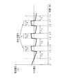
- FIG. 2 is a graph schematically showing the time change of the battery voltage when regenerative charging occurs during the discharge of the secondary battery 2.
- the vertical axis represents battery voltage (V)
- the horizontal axis represents time (seconds).
- the battery voltage changes from a state higher than the N% voltage to a lower state.
- regenerative charging occurs during time (Td) from time t2 to t3 after time t1, time (Te) from time t4 to t5, and time (Tf) from time t6 to t7
- the battery voltage is higher than the N% voltage. That is, the battery voltage is N during the time (Ta) from time t1 to t2, the time (Tb) from time t3 to t4, the time (Tc) from time t5 to t6, and after time t7.
- the state below the% voltage continues.
- Ta, Tb, and Tc are all shorter than Tn.
- Time measurement of the time during which the state where the battery voltage is lower than the N% voltage continues is first started at time t1 with initialization of the time measurement result.
- time t1 time
- time t3, t5, and t7 when the time measurement is started with initialization of the time measurement results, the remaining capacity becomes N% because Ta, Tb, and Tc are all shorter than Tn.
- the corrected timing is delayed at least from the time t7 until after the lapse of Tn. Therefore, in the first embodiment, the time measurement is only temporarily interrupted between time t2 to t3, t4 to t5, t6 to t7, and the time measurement result from time t1 is the time It will be taken over until t7.
- the remaining capacity is corrected to N% at time tx when the following expression (1) is established.
- time tx is a time after time t7
- Tx is a time from time t7 to tx.
- Tn Ta + Tb + Tc + Tx (1)
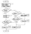
- FIG. 3 is a flowchart showing a processing procedure of the CPU 61 of the remaining capacity correction device 3 according to the first embodiment.
- FIG. 4 is a flowchart showing a processing procedure of the CPU 61 for calculating the charging current and the discharging current.
- the battery voltage is also calculated by the same process as in FIG. 4, but the description thereof is omitted.
- the processes in FIGS. 3 and 4 are started at a 250 ms period and a 10 ms period, but are not limited thereto.
- the CPU 61 determines whether or not the battery voltage (the voltage obtained by averaging the voltages of the secondary batteries 2) is lower than the N% voltage (S11).
- the voltage value of the N% voltage (for example, 3.1 V in the case of the 10% voltage) is read from the ROM 62.
- the CPU 61 determines that the value of the charging current calculated in step S27 of FIG. It is determined whether it is larger, that is, whether the secondary battery 2 is charged (S12).
- the CPU 61 clears the number of detections to zero (S15). Thereby, the number of detections can be initialized in advance before time t1 shown in FIG.
- the CPU 61 clears the N% detection flag (S16), and ends the process of FIG.
- step S11 If the battery voltage is lower than the N% voltage in step S11 (S11: YES), the CPU 61 increments the number of detections by 1 (S17), and then the number of detections is greater than the N% determination number (Cn described above). Is determined (S18). The value of Cn is read from the RAM 63. If the number is greater than the N% determination number (S18: YES), the CPU 61 sets an N% detection flag (S19) and ends the process of FIG. On the other hand, if it is not greater than the N% determination count (S18: NO), the CPU 61 shifts the processing to step S16 in order to clear the N% detection flag.
- the charging / discharging current is captured every time the system is activated at a cycle of 10 ms, and the captured current is divided into a charging current and a discharging current, and is accumulated separately as an additional charging current and an additional discharging current.
- the current obtained by dividing each of the accumulated additional charging current and the additional discharging current by 25 is set as the charging current and the discharging current. .
- the CPU 61 captures a digital detection value (hereinafter also referred to as Icd) related to the charge / discharge current from an A / D converter (not shown) (S21), and the captured detection value indicates It is determined whether or not the current is a current in the charging direction (S22). Whether the current is in the charging direction is determined by the polarity of the detected value.
- the CPU 61 adds the absolute value of Icd to the added charging current (Ic) (S23).
- the CPU 61 adds the absolute value of Icd to the added discharge current (Id) (S24).
- step S23 or S24 the CPU 61 increments the addition counter by 1 (S25), and then determines whether or not the addition counter is 25 (S26). When the addition counter is not 25 (S26: NO), the CPU 61 waits for the process of FIG. 4 to be started again after 10 ms, and temporarily ends the process of FIG.
- the CPU 61 sets the value of the additional charging current (Ic) to 25. After the value divided by is set as the charging current (S27), Ic is cleared to zero (S28). Next, the CPU 61 sets the value obtained by dividing the value of the added discharge current (Id) by 25 as the discharge current (S29), then clears Id to zero (S30), further clears the addition counter to zero (S31), and FIG. Terminate the process.
- the voltage of the secondary battery detected in time series is not lower than the N% voltage, and the current in the charging direction among the charge / discharge currents detected in time series is calculated.
- the counting of the number of times that the voltage of the secondary battery is determined to be lower than the N% voltage is interrupted. Thereby, when charging occurs in the secondary battery and the voltage becomes higher than the N% voltage, the count result (number of detections) of the number of times that the voltage of the secondary battery is determined to be lower than the N% voltage is 0. Held without being initialized.
- the secondary capacity can be corrected appropriately by continuing the determination before and after charging. It is possible to provide a battery remaining capacity correcting method, a secondary battery remaining capacity correcting apparatus, and a secondary battery apparatus.
- the secondary battery remaining capacity correction device integrates the remaining capacity of the secondary battery and corrects the accumulated remaining capacity. Therefore, even when charging occurs during the determination for correcting the remaining capacity of the secondary battery, the secondary capacity can be corrected appropriately by continuing the determination before and after charging.
- the battery remaining capacity correction device can be applied to a secondary battery device.
- the first embodiment is a mode in which the time measurement result is taken over even if regenerative charging occurs after the time measurement of the time during which the battery voltage is lower than the N% voltage is once started.
- the second embodiment is a form in which the time measurement once started is stopped during charging and the time measurement result is initialized depending on the relationship with the time during which regenerative charging is performed.
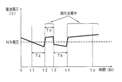
- FIG. 5 is a graph schematically showing changes in battery voltage over time when regenerative charging with a long duration occurs during discharge of the secondary battery 2.
- the vertical axis represents the battery voltage (V)
- the horizontal axis represents time (seconds).
- the change in the battery voltage up to time t4 is the same as in FIG. 2, whereas the duration of regenerative charging that occurred at time t4 is longer than in FIG.
- the ratio of regenerative charging increases with respect to discharge, the remaining capacity when the remaining capacity of the secondary battery starts to count the time during which the battery voltage is lower than the N% voltage continues. It is appropriate to stop the determination for correcting the remaining capacity when approaching.
- the time measurement is stopped when the integrated value of the charging current during the regenerative charging becomes greater than the integrated value of the discharging current during the discharge by a predetermined value ( ⁇ ) or more.
- ⁇ a predetermined value
- time ty is a time after time t4.
- ⁇ is a value whose absolute value is about 0.1% of the learning capacity of the secondary battery 2 and may take a negative value.
- FIG. 6 is a flowchart showing a processing procedure of the CPU 61 of the remaining capacity correction device 3 according to the second embodiment.
- the processing from step S111 to S119 is the same as the processing from step S11 to S19 shown in FIG.
- each of the processes in steps S112, S115, and S116 corresponds to the processes in steps S12, S15, and S16 shown in FIG.
- the “integrated charge / discharge current” indicating the integrated value of the charge / discharge current is stored in the RAM 63.
- the CPU 61 adds and subtracts the respective values of the charging current and the discharging current with respect to the integrated charging / discharging current.
- Each of the charging current and the discharging current is calculated in steps S27 and S29 in the processing shown in FIG. 4 of the first embodiment, and is stored in the RAM 63.
- the CPU 61 determines whether or not the battery voltage is lower than the N% voltage (S111). If not lower (S111: NO), the value of the charging current is greater than 0, that is, the secondary battery 2 is It is determined whether or not the battery is charged (S112).
- the CPU 61 clears the accumulated charge / discharge current to zero (S113) and then clears the number of detections to zero (S115). Thereby, the integrated charge / discharge current and the number of detections can be initialized in advance before time t1 shown in FIG. Thereafter, the CPU 61 clears the N% detection flag (S116) and ends the process of FIG.
- step S112 When the secondary battery 2 is charged in step S112 (S112: YES), the CPU 61 determines whether or not the integrated charge / discharge current is larger than ⁇ (see formula (2)) (S114). (S114: NO), the process proceeds to step S116. On the other hand, when larger than ⁇ (S114: YES), the CPU 61 shifts the processing to step S115. Thereby, the count result of the number of times when the battery voltage is determined to be lower than the N% voltage is initialized (cleared).
- the counting of the number of times is started.
- the count result of the number of times is initialized to zero. Therefore, when the secondary battery is charged and the remaining capacity of the secondary battery approaches the remaining capacity when the counting is started, the determination for correcting the remaining capacity is repeated from the beginning. Is possible.
Landscapes
- Engineering & Computer Science (AREA)
- Power Engineering (AREA)
- Manufacturing & Machinery (AREA)
- Chemical & Material Sciences (AREA)
- Chemical Kinetics & Catalysis (AREA)
- Electrochemistry (AREA)
- General Chemical & Material Sciences (AREA)
- Life Sciences & Earth Sciences (AREA)
- Sustainable Development (AREA)
- Sustainable Energy (AREA)
- Transportation (AREA)
- Mechanical Engineering (AREA)
- Physics & Mathematics (AREA)
- General Physics & Mathematics (AREA)
- Secondary Cells (AREA)
- Charge And Discharge Circuits For Batteries Or The Like (AREA)
Abstract
【課題】二次電池の残容量を補正するための判定の継続中に充電が発生した場合であっても、充電の前後で判定を継続させて残容量を適正に補正することが可能な二次電池の残容量補正方法、二次電池の残容量補正装置及び二次電池装置を提供する。 【解決手段】10msごとに検出して25回平均化した二次電池の電圧がN%電圧より低くなく、且つ、10msごとに検出した充放電電流のうち充電方向の電流を25回平均化した充電電流の値が0より大きいことから二次電池が充電中と判定される場合、即ち、時刻t2からt3までの時間Tdの間と、時刻t4からt5までの時間Teの間と、時刻t6からt7までの時間Tfの間とで、二次電池の電圧がN%電圧より低いと判定される回数の計数を中断する。時刻t3,t5,t7で充電が終了して二次電池の電圧がN%電圧より低くなったときに、それまで保留されていた計数結果を引き継いで前記回数の計数を再開する。
Description
本発明は、充放電に伴う二次電池の残容量を積算して適正に補正する二次電池の残容量補正方法、二次電池の残容量補正装置及び該二次電池の残容量補正装置を備える二次電池装置に関する。
従来、パーソナルコンピュータ等の電子機器に搭載される二次電池の残容量は、例えば、満充電での電気量(電流値×時間)又は電力量(電力値×時間)の夫々に対して、充放電電流又は充放電電力の積算値(以下、充放電容量という)を加算して算出されている。算出された残容量は、満充電での残容量に対する割合(%)として表すことができる。
このような積算による残容量と、実際の残容量との差が拡大するのを防止するため、二次電池の電圧が所定の残容量に対応する電圧(例えば、残容量がN%であることを示す既知の電圧。Nは一般的には10程度の自然数)より低下した場合に、積算した残容量をN%に補正する方法が知られている。またこの場合、満充電のときから積算した放電容量-充電容量を(1-N/100)で除して得た容量を、二次電池の総容量(学習容量)とすることも行われている。
例えば、特許文献1では、N%の残容量に対応する既知の判定電圧を二次電池の電圧が下回る時間が、判定時間以上となったときに残容量を補正するに際し、判定中の放電電流の大/小に応じて、判定電圧を高/低に変更する一方で、判定電圧に応じて短/長に変更すべき判定時間のうち最も長い判定時間を用いる技術が開示されている。この技術により、二次電池の残容量の補正が、より的確に行われる。
しかしながら、近年の二次電池は、電動バイク、電動自転車等の電動車両に用いられることがあり、電力回生が行われる電動車両において二次電池の充電が断続的に発生した場合、特許文献1に開示された技術では、充電が発生する都度、二次電池の電圧が判定電圧を下回る状態の継続時間の計時結果が初期化されるため、残容量の補正が適正に行えないという問題があった。
本発明は斯かる事情に鑑みてなされたものであり、その目的とするところは、二次電池の残容量を補正するための判定の継続中に充電が発生した場合であっても、充電の前後で判定を継続させて残容量を適正に補正することが可能な二次電池の残容量補正方法、二次電池の残容量補正装置及び二次電池装置を提供することにある。
本発明に係る二次電池の残容量補正方法は、二次電池の電圧及び充放電電流を時系列的に検出して残容量を積算すると共に、検出した電圧が所定電圧より低いと判定した回数を計数し、計数した回数が所定回数より多い場合、残容量を所定容量に補正する二次電池の残容量補正方法において、検出した電圧が前記所定電圧より低くないと判定した場合、検出した充放電電流に基づいて前記二次電池が充電しているか否かを判定し、充電していると判定した場合、前記回数の計数を中断することを特徴とする。
本発明に係る二次電池の残容量補正方法は、検出した電圧が前記所定電圧より低いと判定した後における充放電電流を積算し、前記回数の計数を中断した場合、充放電電流の積算値が所定値より大きいか否かを判定し、所定値より大きいと判定した場合、前記回数の計数値を初期化することを特徴とする。
本発明に係る二次電池の残容量補正装置は、二次電池の電圧及び充放電電流を時系列的に検出して残容量を積算すると共に、検出した電圧が所定電圧より低いと判定した回数を計数し、計数した回数が所定回数より多い場合、残容量を所定容量に補正する二次電池の残容量補正装置において、検出した電圧が前記所定電圧より低くないと判定した場合、検出した充放電電流に基づいて前記二次電池が充電しているか否かを判定する手段と、該手段が充電していると判定した場合、前記回数の計数を中断するようにしてあることを特徴とする。
本発明に係る二次電池の残容量補正装置は、検出した電圧が前記所定電圧より低いと判定した後における充放電電流を積算する積算手段と、
前記回数の計数を中断した場合、前記積算手段の積算値が所定値より大きいか否かを判定する判定手段とを備え、前記積算手段は、前記判定手段が所定値より大きいと判定した場合、前記回数の計数値を初期化するようにしてあることを特徴とする。
前記回数の計数を中断した場合、前記積算手段の積算値が所定値より大きいか否かを判定する判定手段とを備え、前記積算手段は、前記判定手段が所定値より大きいと判定した場合、前記回数の計数値を初期化するようにしてあることを特徴とする。
本発明に係る二次電池装置は、前述の二次電池の残容量補正装置と、該残容量補正装置によって残容量が補正される1又は複数の二次電池とを備えることを特徴とする。
本発明にあっては、時系列的に検出した二次電池の電圧が所定電圧より低くなく、且つ、時系列的に検出した充放電電流に基づいて二次電池が充電中と判定される場合に、二次電池の電圧が所定電圧より低いと判定される回数の計数を中断する。
これにより、二次電池に充電が発生して電圧が所定電圧より高くなった場合は、二次電池の電圧が所定電圧より低いと判定された回数の計数結果が初期化されずに保留される。そして、充電が終了して二次電池の電圧が所定電圧より低くなったときに、前記回数の計数が再開され、それまで保留されていた計数結果が、再開された回数の計数に引き継がれる。
これにより、二次電池に充電が発生して電圧が所定電圧より高くなった場合は、二次電池の電圧が所定電圧より低いと判定された回数の計数結果が初期化されずに保留される。そして、充電が終了して二次電池の電圧が所定電圧より低くなったときに、前記回数の計数が再開され、それまで保留されていた計数結果が、再開された回数の計数に引き継がれる。
本発明にあっては、充電が発生して、二次電池の電圧が所定電圧より低いと判定される回数の計数を中断した場合、前記回数の計数を開始した後における充放電電流の積算値が所定値より大きいときは、前記回数の計数結果を初期化する。この場合の所定値は、二次電池の充放電に応じて増減する積算値と比較されるものであり、負の値をとり得る。
これにより、二次電池が充電されたことによって、二次電池の残容量が、前記回数の計数を開始したときの残容量に近づいた場合は、残容量の補正のための判定を最初からやり直すことができる。
これにより、二次電池が充電されたことによって、二次電池の残容量が、前記回数の計数を開始したときの残容量に近づいた場合は、残容量の補正のための判定を最初からやり直すことができる。
本発明にあっては、前述の二次電池の残容量補正装置が、二次電池の残容量を積算すると共に、積算した残容量を補正する。
これにより、二次電池の残容量を補正するための判定の継続中に充電が発生した場合であっても、充電の前後で判定を継続させて残容量を適正に補正することが可能な二次電池の残容量補正装置が、二次電池装置に適用される。
これにより、二次電池の残容量を補正するための判定の継続中に充電が発生した場合であっても、充電の前後で判定を継続させて残容量を適正に補正することが可能な二次電池の残容量補正装置が、二次電池装置に適用される。
本発明によれば、二次電池に充電が発生して電圧が所定電圧より高くなった場合は、二次電池の電圧が所定電圧より低いと判定された回数の計数結果が初期化されずに保留される。そして、充電が終了して前記回数の計数が再開されるときに、保留されていた計数結果が、新たな回数の計数に引き継がれる。
従って、二次電池の残容量を補正するための判定の継続中に充電が発生した場合であっても、充電の前後で判定を継続させて残容量を適正に補正することが可能となる。
従って、二次電池の残容量を補正するための判定の継続中に充電が発生した場合であっても、充電の前後で判定を継続させて残容量を適正に補正することが可能となる。
以下、本発明をその実施の形態を示す図面に基づいて詳述する。
(実施の形態1)
図1は、本発明の実施の形態1に係る二次電池装置の構成例を示すブロック図である。図中1は二次電池装置(パック電池)であり、二次電池装置1は、1又は複数のリチウムイオン電池を直列、並列又は直並列に接続してなる二次電池2と、該二次電池2の正極端子及び負極端子に接続された残容量補正装置3とを備える。二次電池2は、ニッケル水素電池等の他の二次電池とすることもできる。
(実施の形態1)
図1は、本発明の実施の形態1に係る二次電池装置の構成例を示すブロック図である。図中1は二次電池装置(パック電池)であり、二次電池装置1は、1又は複数のリチウムイオン電池を直列、並列又は直並列に接続してなる二次電池2と、該二次電池2の正極端子及び負極端子に接続された残容量補正装置3とを備える。二次電池2は、ニッケル水素電池等の他の二次電池とすることもできる。
残容量補正装置3は、二次電池2の正極端子及び負極端子に接続されて二次電池2の電圧を検出する電圧検出部4と、二次電池2の負極端子に一端が接続されて二次電池2の充放電電流を検出する電流検出部5と、これらの検出部から与えられた検出値に基づいて残容量を算出する制御部6とを備える。制御部6には、二次電池2に熱結合された温度センサ71を用いて二次電池2の温度を検出する温度検出部7と、算出された残容量のデータを外部の電気機器に通信端子81を介して送信するための通信部8とが接続されている。二次電池2の正極端子及び電流検出部5の他端子の夫々は、+(プラス)端子21及び-(マイナス)端子22を介して外部の電気機器と接続されるようになっている。
制御部6は、CPU61を有し、CPU61は、プログラム等の情報を記憶するROM62、一時的に発生した情報を記憶するRAM63、通信部8、及び図示しないA/D変換器と互いにバス接続されている。A/D変換器の複数のアナログ入力端子には、電圧検出部4、電流検出部5及び温度検出部7夫々の検出出力端子が接続されている。ROM62は、EEPROM(Electrically Erasable Programmable ROM )又はフラッシュメモリからなる不揮発性メモリであり、ROM62には、プログラムの他に、二次電池2の学習容量、残容量、充放電のサイクル数、異常時の各検出値等の保存データ、及び残容量を補正するための各種設定データが記憶される。
電流検出部5は、抵抗値が低い抵抗素子からなり、この抵抗素子に二次電池2の充放電電流が流れたときの降下電圧を、アナログの検出信号として上記A/D変換器に与える。この場合のアナログの検出信号の極性は、二次電池2に対する充電及び放電の夫々に応じて正及び負となる。抵抗素子に代えてトランジスタ、FET等の半導体を用いることもできる。抵抗素子を用いることなく、二次電池2の負極端子と-端子22とをリード線にて直結しておき、このリード線から発生する磁界を検出することによって、リード線に流れる充放電電流を検出するようにしてもよい。
電圧検出部4は、二次電池2の電圧を検出してアナログの検出信号をA/D変換器に与える。
電圧検出部4、電流検出部5及び温度検出部7からアナログの検出信号を与えられたA/D変換器は、アナログの各検出信号をデジタルの検出値に変換する。変換されたデジタルの検出値は、CPU61に適宜取り込まれる。
電圧検出部4、電流検出部5及び温度検出部7からアナログの検出信号を与えられたA/D変換器は、アナログの各検出信号をデジタルの検出値に変換する。変換されたデジタルの検出値は、CPU61に適宜取り込まれる。
CPU61は、ROM62に予め格納されている制御プログラムに従って、入出力及び演算等の処理を実行する。本実施の形態1では、CPU61は、上記A/D変換器から、二次電池2の電圧及び充放電電流に係るデジタルの検出値を10ms周期で取り込み、取り込んだ検出値の平均値として、電池電圧、充電電流及び放電電流を250ms周期で算出する。CPU61は、また、算出した放電電流を250ms周期で積算して放電容量を算出し、算出した放電容量を、満充電容量(学習容量)から減算して残容量を算出する。従って、二次電池2が満充電の状態から放電される時間の経過と共に、残容量が低下する。
CPU61は、更に、残容量がN%であることを示す電池電圧(以下、N%電圧という)よりも、算出した電池電圧が低くなる状態が、Tnで示される時間(以下、N%判定時間ともいう)より長く継続した場合、残容量をN%に補正する。例えば、二次電池2がリチウムイオン電池の場合、残容量が10%であることを示す電池電圧は3.1V/セルである。時間の計時に代えて、250msの定周期処理における判定の継続回数を計数する場合は、秒単位のTnの値の4倍の回数を示すCn(以下、N%判定回数ともいう)だけ、継続回数を計数する。N%電圧の電圧値、Nの値、並びにTn及びCnの値は、ROM62に記憶されている。これらの値は、温度検出部7で検出された二次電池2の温度に応じて適当に変更してもよい。
さて、二次電池装置1に接続されるべき外部の電気機器は、双方向電力変換装置を介して二次電池装置1から電力を送給されるモータを備える電動バイク、電動アシスト自転車等の電動車両である。例えば電動バイクの場合、運転者がアクセルレバーから手を離したときにモータにて回生電力が発生し、双方向電力変換装置が変換する電力が二次電池装置1側に回生されて、二次電池2が充電(以下、回生充電という)される。同様に電動アシスト自転車の場合、例えば下り坂を走行中に回生電力が発生して、二次電池2が回生充電される。
ところで、二次電池2が放電中に充電が断続的に発生する場合、電池電圧がN%電圧より低くなる状態が、充電の都度一旦解消されるときは、残容量をN%に補正するタイミングが遅れる虞がある。以下、そのような場合が発生する様子と、本実施の形態1における処理方法について、図を用いて説明する。
図2は、二次電池2の放電中に回生充電が発生した場合の電池電圧の時間変化を模式的に示すグラフである。図2において、縦軸は電池電圧(V)を表し、横軸は時間(秒)を表す。
図2は、二次電池2の放電中に回生充電が発生した場合の電池電圧の時間変化を模式的に示すグラフである。図2において、縦軸は電池電圧(V)を表し、横軸は時間(秒)を表す。
図2では、時刻t1の前後で、電池電圧がN%電圧より高い状態から低い状態に変化する。そして、時刻t1より後の時刻t2からt3までの時間(Td)、時刻t4からt5までの時間(Te)、及び時刻t6からt7までの時間(Tf)の間は回生充電が発生して、電池電圧がN%電圧より高くなっている。つまり、時刻t1からt2までの時間(Ta)、時刻t3からt4までの時間(Tb)、及び時刻t5からt6までの時間(Tc)の間と、時刻t7より後とでは、電池電圧がN%電圧より低い状態が継続している。但し、Ta,Tb,Tcは、何れもTnより短い。
電池電圧がN%電圧より低い状態が継続する時間の計時は、先ず最初に時刻t1において計時結果の初期化を伴って開始される。ここで、時刻t3,t5,t7においても、前記時間の計時が計時結果の初期化を伴って開始された場合は、Ta,Tb,Tcが何れもTnより短いため、残容量がN%に補正されるタイミングが、少なくとも時刻t7からTnの経過後まで遅れることとなる。そこで、本実施の形態1では、時刻t2からt3,t4からt5,t6からt7の間は、前記時間の計時が一旦中断されるのみとし、時刻t1から開始された計時による計時結果が、時刻t7以降まで引き継がれるようにする。
具体的には、電池電圧がN%電圧より高くなった場合であっても、充電が発生しているときは、一旦開始された継続時間の計時が中断されて計時結果が保留される。その後、充電が終了して再び電池電圧がN%電圧より低くなった場合、それまで中断されていた継続時間の計時が再開されるときに、それまで保留されていた計時結果が引き継がれるようにする。
これにより、例えば以下の式(1)が成立する時刻txにおいて、残容量がN%に補正される。但し、時刻txは時刻t7より後の時刻であり、Txは時刻t7からtxまでの時間である。
これにより、例えば以下の式(1)が成立する時刻txにおいて、残容量がN%に補正される。但し、時刻txは時刻t7より後の時刻であり、Txは時刻t7からtxまでの時間である。
Tn=Ta+Tb+Tc+Tx・・・・・・・・・・・・・・・・・・(1)
以下では、上述した残容量補正装置3の動作を、それを示すフローチャートを用いて説明する。以下に示す処理は、ROM62に予め格納された制御プログラムに従ってCPU61により実行される。
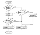
図3は、実施の形態1に係る残容量補正装置3のCPU61の処理手順を示すフローチャートである。また、図4は、充電電流及び放電電流を算出するCPU61の処理手順を示すフローチャートである。電池電圧についても、図4と同様の処理によって算出されるが、その説明を省略する。図3及び図4夫々の処理は、250ms周期及び10ms周期で起動されるが、これに限定されるものではない。
図3は、実施の形態1に係る残容量補正装置3のCPU61の処理手順を示すフローチャートである。また、図4は、充電電流及び放電電流を算出するCPU61の処理手順を示すフローチャートである。電池電圧についても、図4と同様の処理によって算出されるが、その説明を省略する。図3及び図4夫々の処理は、250ms周期及び10ms周期で起動されるが、これに限定されるものではない。
尚、図3において、電池電圧がN%電圧より低いと判定された回数の計数結果を示す「検出回数」と、該「検出回数」がN%判定回数より多くなったか否かを示す「N%検出フラグ」とは、RAM63に記憶される。図3の処理によってN%検出フラグが「1」にセットされた場合、図示しない残容量補正処理によって二次電池2の残容量のデータがN%に補正される。
また、図4において算出された「充電電流」及び「放電電流」と、平均化の処理中に一時的に記憶されるべき「加算充電電流(以下、Icともいう)」、「加算放電電流(以下、Idともいう)」及び「加算カウンタ」とは、RAM63に記憶される。図4の処理によって算出された「充電電流」は、図3の処理で参照されるものである。
また、図4において算出された「充電電流」及び「放電電流」と、平均化の処理中に一時的に記憶されるべき「加算充電電流(以下、Icともいう)」、「加算放電電流(以下、Idともいう)」及び「加算カウンタ」とは、RAM63に記憶される。図4の処理によって算出された「充電電流」は、図3の処理で参照されるものである。
図3の処理が起動された場合、CPU61は、電池電圧(二次電池2の電圧が平均化された電圧)が、N%電圧より低いか否かを判定する(S11)。ここで、N%電圧の電圧値(例えば10%電圧の場合の3.1V)は、ROM62から読み出される。電池電圧がN%電圧より低くない場合(S11:NO)、CPU61は、後述する図4のステップS27で算出した充電電流(充放電電流のうち、充電方向の電流の平均値)の値が0より大きいか、即ち、二次電池2が充電されているか否かを判定する(S12)。
二次電池2が充電されていない場合(S12:NO)、CPU61は、検出回数をゼロクリアする(S15)。これにより、図2に示す時刻t1より前に、検出回数を予め初期化することができる。二次電池2が充電されている場合(S12:YES)、又はステップS15の処理を終えた場合、CPU61は、N%検出フラグをクリアして(S16)、図3の処理を終了する。
ステップS11で、電池電圧がN%電圧より低い場合(S11:YES)、CPU61は、検出回数を1だけインクリメントした(S17)後、検出回数がN%判定回数(上述したCn)より多いか否かを判定する(S18)。Cnの値はRAM63から読み出される。N%判定回数より多い場合(S18:YES)、CPU61は、N%検出フラグをセットして(S19)、図3の処理を終了する。一方、N%判定回数より多くない場合(S18:NO)、CPU61は、N%検出フラグをクリアするために、処理をステップS16に移す。
次に、図4の処理について説明する。図4の処理では、10ms周期で起動される毎に充放電電流を取り込み、取り込んだ電流を充電の電流と放電の電流とに振り分けて、加算充電電流及び加算放電電流として各別に積算する。図4の処理が25回目に起動された場合、積算した加算充電電流及び加算放電電流の夫々を25で除して得た電流(250ms間における平均的な電流)を充電電流及び放電電流とする。
図4の処理が起動された場合、CPU61は、図示しないA/D変換器から、充放電電流に係るデジタルの検出値(以下、Icdともいう)を取り込み(S21)、取り込んだ検出値が示す電流が、充電方向の電流であるか否かを判定する(S22)。充電方向の電流であるか否かは、検出値の極性によって判定する。充電方向の電流である場合(S22:YES)、CPU61は、加算充電電流(Ic)にIcdの絶対値を加算する(S23)。一方、充電方向の電流ではない場合(S22:NO)、CPU61は、加算放電電流(Id)にIcdの絶対値を加算する(S24)。
ステップS23又はS24の処理を終えた場合、CPU61は、加算カウンタを1だけインクリメントした(S25)後に、加算カウンタが25であるか否かを判定する(S26)。加算カウンタが25ではない場合(S26:NO)、CPU61は、10ms後に再び図4の処理が起動されるのを待つこととして、図4の処理を一旦終了する。
加算カウンタが25である場合、即ち、充放電電流の検出値を25回取り込んで、その都度充電電流及び放電電流に振り分ける処理を終えた場合、CPU61は、加算充電電流(Ic)の値を25で除した値を充電電流とした(S27)後に、Icをゼロクリアする(S28)。次いで、CPU61は、加算放電電流(Id)の値を25で除した値を放電電流とした(S29)後に、Idをゼロクリアし(S30)、更に加算カウンタをゼロクリアして(S31)、図4の処理を終了する。
以上にように本実施の形態1によれば、時系列的に検出した二次電池の電圧がN%電圧より低くなく、且つ、時系列的に検出した充放電電流のうち充電方向の電流を平均化した充電電流の値が0より大きいことから二次電池が充電中と判定される場合に、二次電池の電圧がN%電圧より低いと判定される回数の計数を中断する。
これにより、二次電池に充電が発生して電圧がN%電圧より高くなった場合は、二次電池の電圧がN%電圧より低いと判定された回数の計数結果(検出回数)が0に初期化されずに保留される。そして、充電が終了して二次電池の電圧がN%電圧より低くなったときに、前記回数の計数が再開され、それまで保留されていた計数結果が、再開された回数の計数に引き継がれる。
従って、二次電池の残容量を補正するための判定の継続中に充電が発生した場合であっても、充電の前後で判定を継続させて残容量を適正に補正することが可能な二次電池の残容量補正方法、二次電池の残容量補正装置及び二次電池装置を提供することが可能となる。
これにより、二次電池に充電が発生して電圧がN%電圧より高くなった場合は、二次電池の電圧がN%電圧より低いと判定された回数の計数結果(検出回数)が0に初期化されずに保留される。そして、充電が終了して二次電池の電圧がN%電圧より低くなったときに、前記回数の計数が再開され、それまで保留されていた計数結果が、再開された回数の計数に引き継がれる。
従って、二次電池の残容量を補正するための判定の継続中に充電が発生した場合であっても、充電の前後で判定を継続させて残容量を適正に補正することが可能な二次電池の残容量補正方法、二次電池の残容量補正装置及び二次電池装置を提供することが可能となる。
また、二次電池の残容量補正装置が、二次電池の残容量を積算すると共に、積算した残容量を補正する。
従って、二次電池の残容量を補正するための判定の継続中に充電が発生した場合であっても、充電の前後で判定を継続させて残容量を適正に補正することが可能な二次電池の残容量補正装置を、二次電池装置に適用することが可能となる。
従って、二次電池の残容量を補正するための判定の継続中に充電が発生した場合であっても、充電の前後で判定を継続させて残容量を適正に補正することが可能な二次電池の残容量補正装置を、二次電池装置に適用することが可能となる。
(実施の形態2)
実施の形態1は、電池電圧がN%電圧より低い状態が継続する時間の計時が一旦開始された後は、回生充電が発生した場合であっても計時結果が引き継がれる形態であるのに対し、実施の形態2は、回生充電が行われる時間との関係により、一旦開始された前記時間の計時が充電中に中止されて計時結果が初期化されることがある形態である。
実施の形態1は、電池電圧がN%電圧より低い状態が継続する時間の計時が一旦開始された後は、回生充電が発生した場合であっても計時結果が引き継がれる形態であるのに対し、実施の形態2は、回生充電が行われる時間との関係により、一旦開始された前記時間の計時が充電中に中止されて計時結果が初期化されることがある形態である。
図5は、二次電池2の放電中に継続時間が長い回生充電が発生した場合の電池電圧の時間変化を模式的に示すグラフである。図2と同様に、縦軸は電池電圧(V)を表し、横軸は時間(秒)を表す。図5では、時刻t4に至るまでの電池電圧の変化が、図2の場合と同一であるのに対し、時刻t4で発生した回生充電の継続時間が、図2の場合より長くなっている。このように、放電に対して回生充電の割合が増加して行く場合は、二次電池の残容量が、電池電圧がN%電圧より低い状態が継続する時間の計時を開始したときの残容量に近づいたときに、残容量の補正のための判定を中止するのが適当である。
そこで、本実施の形態2では、回生充電中の充電電流の積算値が、放電中の放電電流の積算値より所定値(α)以上大きくなった場合に、前記時間の計時を中止する。これにより、例えば以下の式(2)が成立する時刻tyにおいて、残容量をN%に補正するための一連の判定処理が中止される。但し、時刻tyは時刻t4より後の時刻である。また、αは、絶対値が二次電池2の学習容量の0.1%程度の値であり、負の値をとり得る。
(時刻t2からt3までの間の充電電流の積算値)
+(時刻t4からtyまでの間の充電電流の積算値)
-(時刻t1からt2までの間の放電電流の積算値)
-(時刻t3からt4までの間の放電電流の積算値)>α・・・・・・・(2)
+(時刻t4からtyまでの間の充電電流の積算値)
-(時刻t1からt2までの間の放電電流の積算値)
-(時刻t3からt4までの間の放電電流の積算値)>α・・・・・・・(2)
以下では、実施の形態2に係る残容量補正装置3の動作を、それを示すフローチャートを用いて説明する。
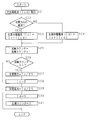
図6は、実施の形態2に係る残容量補正装置3のCPU61の処理手順を示すフローチャートである。図5に示す処理のうち、ステップS111からS119までの処理は、実施の形態1の図3に示すステップS11からS19までの処理と同一であるため、その説明の大部分を省略する。また、ステップS112,S115,S116の処理の夫々は、図3に示すステップS12,S15,S16の処理と対応している。
尚、充放電電流の積算値を示す「積算充放電電流」は、RAM63に記憶される。
図6は、実施の形態2に係る残容量補正装置3のCPU61の処理手順を示すフローチャートである。図5に示す処理のうち、ステップS111からS119までの処理は、実施の形態1の図3に示すステップS11からS19までの処理と同一であるため、その説明の大部分を省略する。また、ステップS112,S115,S116の処理の夫々は、図3に示すステップS12,S15,S16の処理と対応している。
尚、充放電電流の積算値を示す「積算充放電電流」は、RAM63に記憶される。
図6の処理が起動された場合、CPU61は、積算充放電電流に対して、充電電流及び放電電流夫々の値を加算及び減算する。充電電流及び放電電流の夫々は、実施の形態1の図4に示す処理のうち、ステップS27及びS29にて算出したものであり、RAM63に記憶されている。その後、CPU61は、電池電圧が、N%電圧より低いか否かを判定し(S111)、低くない場合(S111:NO)、充電電流の値が0より大きいか、即ち、二次電池2が充電されているか否かを判定する(S112)。
二次電池2が充電されていない場合(S112:NO)、CPU61は、積算充放電電流をゼロクリアした(S113)後に、検出回数をゼロクリアする(S115)。これにより、図5に示す時刻t1より前に、積算充放電電流と検出回数とを予め初期化することができる。その後、CPU61は、N%検出フラグをクリアして(S116)、図6の処理を終了する。
ステップS112で二次電池2が充電されている場合(S112:YES)、CPU61は、積算充放電電流がα(式(2)参照)より大きいか否かを判定し(S114)、大きくない場合(S114:NO)、処理をステップS116に移す。一方、αより大きい場合(S114:YES)、CPU61は、処理をステップS115に移す。これにより、電池電圧がN%電圧より低いと判定された回数の計数結果が初期化(クリア)される。
その他、実施の形態1に対応する箇所には同様の符号を付して、その詳細な説明を省略する。
以上のように、本実施の形態2によれば、充電が発生して、二次電池の電圧がN%電圧より低いと判定される回数の計数を中断した場合、前記回数の計数を開始した後に充放電電流を積算した積算充放電電流の値がαより大きいときは、前記回数の計数結果を0に初期化する。
従って、二次電池が充電されたことによって、二次電池の残容量が、前記回数の計数を開始したときの残容量に近づいた場合は、残容量の補正のための判定を最初からやり直すことが可能となる。
従って、二次電池が充電されたことによって、二次電池の残容量が、前記回数の計数を開始したときの残容量に近づいた場合は、残容量の補正のための判定を最初からやり直すことが可能となる。
今回開示された実施の形態は、全ての点で例示であって、制限的なものではないと考えられるべきである。本発明の範囲は、上述した意味ではなく、特許請求の範囲によって示され、特許請求の範囲と均等の意味及び範囲内での全ての変更が含まれることが意図される。
1 二次電池装置
2 二次電池
3 残容量補正装置
4 電圧検出部
5 電流検出部
6 制御部
61 CPU
63 RAM
8 通信部
2 二次電池
3 残容量補正装置
4 電圧検出部
5 電流検出部
6 制御部
61 CPU
63 RAM
8 通信部
Claims (5)
- 二次電池の電圧及び充放電電流を時系列的に検出して残容量を積算すると共に、検出した電圧が所定電圧より低いと判定した回数を計数し、計数した回数が所定回数より多い場合、残容量を所定容量に補正する二次電池の残容量補正方法において、
検出した電圧が前記所定電圧より低くないと判定した場合、検出した充放電電流に基づいて前記二次電池が充電しているか否かを判定し、
充電していると判定した場合、前記回数の計数を中断すること
を特徴とする二次電池の残容量補正方法。 - 検出した電圧が前記所定電圧より低いと判定した後における充放電電流を積算し、
前記回数の計数を中断した場合、充放電電流の積算値が所定値より大きいか否かを判定し、
所定値より大きいと判定した場合、前記回数の計数値を初期化すること
を特徴とする請求項1に記載の二次電池の残容量補正方法。 - 二次電池の電圧及び充放電電流を時系列的に検出して残容量を積算すると共に、検出した電圧が所定電圧より低いと判定した回数を計数し、計数した回数が所定回数より多い場合、残容量を所定容量に補正する二次電池の残容量補正装置において、
検出した電圧が前記所定電圧より低くないと判定した場合、検出した充放電電流に基づいて前記二次電池が充電しているか否かを判定する手段と、
該手段が充電していると判定した場合、前記回数の計数を中断するようにしてあること を特徴とする二次電池の残容量補正装置。 - 検出した電圧が前記所定電圧より低いと判定した後における充放電電流を積算する積算手段と、
前記回数の計数を中断した場合、前記積算手段の積算値が所定値より大きいか否かを判定する判定手段とを備え、
前記積算手段は、前記判定手段が所定値より大きいと判定した場合、前記回数の計数値を初期化するようにしてあること
を特徴とする請求項3に記載の二次電池の残容量補正装置。 - 請求項3又は4に記載の二次電池の残容量補正装置と、該残容量補正装置によって残容量が補正される1又は複数の二次電池とを備えることを特徴とする二次電池装置。
Priority Applications (1)
| Application Number | Priority Date | Filing Date | Title |
|---|---|---|---|
| JP2012544168A JP5833018B2 (ja) | 2010-11-17 | 2011-10-27 | 二次電池の残容量補正方法、二次電池の残容量補正装置及び二次電池装置 |
Applications Claiming Priority (2)
| Application Number | Priority Date | Filing Date | Title |
|---|---|---|---|
| JP2010-256935 | 2010-11-17 | ||
| JP2010256935 | 2010-11-17 |
Publications (1)
| Publication Number | Publication Date |
|---|---|
| WO2012066920A1 true WO2012066920A1 (ja) | 2012-05-24 |
Family
ID=46083859
Family Applications (1)
| Application Number | Title | Priority Date | Filing Date |
|---|---|---|---|
| PCT/JP2011/074843 Ceased WO2012066920A1 (ja) | 2010-11-17 | 2011-10-27 | 二次電池の残容量補正方法、二次電池の残容量補正装置及び二次電池装置 |
Country Status (2)
| Country | Link |
|---|---|
| JP (1) | JP5833018B2 (ja) |
| WO (1) | WO2012066920A1 (ja) |
Cited By (1)
| Publication number | Priority date | Publication date | Assignee | Title |
|---|---|---|---|---|
| US11209491B2 (en) * | 2018-12-06 | 2021-12-28 | Stl Technology Co., Ltd. | Estimation method for state of charge of battery |
Citations (3)
| Publication number | Priority date | Publication date | Assignee | Title |
|---|---|---|---|---|
| JPS6415679A (en) * | 1987-11-19 | 1989-01-19 | Hitachi Maxell | Battery capacity display method |
| JPH0587896A (ja) * | 1991-09-30 | 1993-04-06 | Pfu Ltd | バツテリ残量検出・補正方式 |
| JP2010164322A (ja) * | 2009-01-13 | 2010-07-29 | Sanyo Electric Co Ltd | 電池残容量検出方法、電池残容量検出装置および二次電池装置 |
-
2011
- 2011-10-27 JP JP2012544168A patent/JP5833018B2/ja active Active
- 2011-10-27 WO PCT/JP2011/074843 patent/WO2012066920A1/ja not_active Ceased
Patent Citations (3)
| Publication number | Priority date | Publication date | Assignee | Title |
|---|---|---|---|---|
| JPS6415679A (en) * | 1987-11-19 | 1989-01-19 | Hitachi Maxell | Battery capacity display method |
| JPH0587896A (ja) * | 1991-09-30 | 1993-04-06 | Pfu Ltd | バツテリ残量検出・補正方式 |
| JP2010164322A (ja) * | 2009-01-13 | 2010-07-29 | Sanyo Electric Co Ltd | 電池残容量検出方法、電池残容量検出装置および二次電池装置 |
Cited By (1)
| Publication number | Priority date | Publication date | Assignee | Title |
|---|---|---|---|---|
| US11209491B2 (en) * | 2018-12-06 | 2021-12-28 | Stl Technology Co., Ltd. | Estimation method for state of charge of battery |
Also Published As
| Publication number | Publication date |
|---|---|
| JPWO2012066920A1 (ja) | 2014-05-12 |
| JP5833018B2 (ja) | 2015-12-16 |
Similar Documents
| Publication | Publication Date | Title |
|---|---|---|
| US8269463B2 (en) | Battery abnormality detection circuit and power supply device | |
| EP2899841B1 (en) | Charging control device and charging time calculation method | |
| EP2362478B1 (en) | Determination system and determination method for determining whether metal lithium is precipitated in a lithium ion secondary battery, and vehicle equipped with the determination system | |
| JP3960241B2 (ja) | 二次電池の残存容量推定装置、二次電池の残存容量推定方法、および二次電池の残存容量推定方法による処理をコンピュータに実行させるためのプログラムを記録したコンピュータ読取可能な記録媒体 | |
| CN105599632B (zh) | 一种基于电动车的电池管理方法和系统 | |
| JP5565276B2 (ja) | リチウムイオン電池の蓄電量補正方法 | |
| JP6672743B2 (ja) | 満充電容量算出装置、コンピュータプログラム及び満充電容量算出方法 | |
| WO2008065910A1 (en) | Accumulator failure detecting device, accumulator failure detecting method, accumulator failure detecting program, and computer-readable recording medium containing the accumulator failure detecting program | |
| US20150355286A1 (en) | System for estimating failure in cell module | |
| JP6171127B2 (ja) | 電池制御システム、車両制御システム | |
| US9184613B2 (en) | Secondary battery state detecting apparatus and secondary battery state detecting method | |
| JP5838224B2 (ja) | 電池制御装置 | |
| CN102282478A (zh) | 电池组、半导体集成电路、剩余容量修正方法以及存储介质 | |
| JP5641215B2 (ja) | 二次電池の制御装置 | |
| CN106394273A (zh) | 用于车辆的电源系统 | |
| CN103097169A (zh) | 充电方法和充电系统 | |
| JP2015156729A (ja) | 充電制御装置 | |
| JP2012002660A (ja) | 二次電池装置 | |
| CN106740131A (zh) | 电动汽车电池电量的监控方法、装置及系统、监控服务器 | |
| JP6631377B2 (ja) | 充電量算出装置、コンピュータプログラム及び充電量算出方法 | |
| CN111183363B (zh) | 劣化量推定装置、蓄电系统、劣化量推定方法、及计算机程序产品 | |
| CN111624491A (zh) | 一种确定电池剩余电量的方法、装置及电池管理系统 | |
| JP5833018B2 (ja) | 二次電池の残容量補正方法、二次電池の残容量補正装置及び二次電池装置 | |
| JP5535092B2 (ja) | 鉛蓄電池状態検出装置および鉛蓄電池状態検出方法 | |
| JP6805837B2 (ja) | 組電池の断線検出方法 |
Legal Events
| Date | Code | Title | Description |
|---|---|---|---|
| 121 | Ep: the epo has been informed by wipo that ep was designated in this application |
Ref document number: 11841403 Country of ref document: EP Kind code of ref document: A1 |
|
| WWE | Wipo information: entry into national phase |
Ref document number: 2012544168 Country of ref document: JP |
|
| NENP | Non-entry into the national phase |
Ref country code: DE |
|
| 122 | Ep: pct application non-entry in european phase |
Ref document number: 11841403 Country of ref document: EP Kind code of ref document: A1 |