WO2012064069A2 - 전송 파워 보고 방법 및 장치 - Google Patents
전송 파워 보고 방법 및 장치 Download PDFInfo
- Publication number
- WO2012064069A2 WO2012064069A2 PCT/KR2011/008444 KR2011008444W WO2012064069A2 WO 2012064069 A2 WO2012064069 A2 WO 2012064069A2 KR 2011008444 W KR2011008444 W KR 2011008444W WO 2012064069 A2 WO2012064069 A2 WO 2012064069A2
- Authority
- WO
- WIPO (PCT)
- Prior art keywords
- power
- set maximum
- reporting
- triggered
- transmission power
- Prior art date
Links
Images


Classifications
-
- H—ELECTRICITY
- H04—ELECTRIC COMMUNICATION TECHNIQUE
- H04W—WIRELESS COMMUNICATION NETWORKS
- H04W52/00—Power management, e.g. TPC [Transmission Power Control], power saving or power classes
- H04W52/04—TPC
- H04W52/18—TPC being performed according to specific parameters
- H04W52/24—TPC being performed according to specific parameters using SIR [Signal to Interference Ratio] or other wireless path parameters
- H04W52/243—TPC being performed according to specific parameters using SIR [Signal to Interference Ratio] or other wireless path parameters taking into account interferences
-
- H—ELECTRICITY
- H04—ELECTRIC COMMUNICATION TECHNIQUE
- H04W—WIRELESS COMMUNICATION NETWORKS
- H04W24/00—Supervisory, monitoring or testing arrangements
- H04W24/10—Scheduling measurement reports ; Arrangements for measurement reports
-
- H—ELECTRICITY
- H04—ELECTRIC COMMUNICATION TECHNIQUE
- H04L—TRANSMISSION OF DIGITAL INFORMATION, e.g. TELEGRAPHIC COMMUNICATION
- H04L5/00—Arrangements affording multiple use of the transmission path
- H04L5/0001—Arrangements for dividing the transmission path
- H04L5/0003—Two-dimensional division
- H04L5/0005—Time-frequency
- H04L5/0007—Time-frequency the frequencies being orthogonal, e.g. OFDM(A), DMT
- H04L5/001—Time-frequency the frequencies being orthogonal, e.g. OFDM(A), DMT the frequencies being arranged in component carriers
-
- H—ELECTRICITY
- H04—ELECTRIC COMMUNICATION TECHNIQUE
- H04L—TRANSMISSION OF DIGITAL INFORMATION, e.g. TELEGRAPHIC COMMUNICATION
- H04L5/00—Arrangements affording multiple use of the transmission path
- H04L5/003—Arrangements for allocating sub-channels of the transmission path
- H04L5/0053—Allocation of signaling, i.e. of overhead other than pilot signals
- H04L5/0055—Physical resource allocation for ACK/NACK
-
- Y—GENERAL TAGGING OF NEW TECHNOLOGICAL DEVELOPMENTS; GENERAL TAGGING OF CROSS-SECTIONAL TECHNOLOGIES SPANNING OVER SEVERAL SECTIONS OF THE IPC; TECHNICAL SUBJECTS COVERED BY FORMER USPC CROSS-REFERENCE ART COLLECTIONS [XRACs] AND DIGESTS
- Y02—TECHNOLOGIES OR APPLICATIONS FOR MITIGATION OR ADAPTATION AGAINST CLIMATE CHANGE
- Y02D—CLIMATE CHANGE MITIGATION TECHNOLOGIES IN INFORMATION AND COMMUNICATION TECHNOLOGIES [ICT], I.E. INFORMATION AND COMMUNICATION TECHNOLOGIES AIMING AT THE REDUCTION OF THEIR OWN ENERGY USE
- Y02D30/00—Reducing energy consumption in communication networks
- Y02D30/70—Reducing energy consumption in communication networks in wireless communication networks
Definitions
- the present invention relates to wireless communication, and more particularly, to a method and apparatus for reporting transmission power of a terminal in a wireless communication system.
- 3GPP LTE long term evolution
- UMTS Universal Mobile Telecommunications System
- 3GPP LTE uses orthogonal frequency division multiple access (OFDMA) in downlink and single carrier-frequency division multiple access (SC-FDMA) in uplink.
- OFDMA orthogonal frequency division multiple access
- SC-FDMA single carrier-frequency division multiple access
- MIMO multiple input multiple output
- LTE-A 3GPP LTE-Advanced
- the transmission power of the terminal In order to mitigate interference due to uplink transmission, the transmission power of the terminal needs to be adjusted. If the transmission power of the terminal is too low, it is difficult for the base station to receive uplink data. If the transmission power of the terminal is too high, uplink transmission may cause too much interference in the transmission of other terminals.
- the terminal In order to determine the uplink transmission power of the terminal, the terminal reports the power headroom to the base station. However, since the power headroom is only a difference between the maximum transmission power and the transmission power to be used, the base station may not accurately determine the available transmission power of the terminal if the terminal arbitrarily limits the transmission power.
- the present invention provides a method and apparatus in which reporting of transmit power is triggered and reporting triggered transmit power.
- a method for reporting transmission power of a terminal in a wireless communication system includes determining a set maximum transmit power based on a transmit power set by a base station and a maximum power reduction (MPR), determining whether a report of the set maximum transmit power is triggered, and the set maximum transmit power If a report of the trigger is triggered, transmitting a report message containing the set maximum transmission power to the base station.
- MPR maximum power reduction
- the method may further include determining a power headroom that is a difference between the set maximum transmission power and the transmission power to be used for uplink transmission, and the report message may further include the power headroom.
- the report of the set maximum transmit power When the report of the set maximum transmit power is set or reset, the report of the set maximum transmit power may be triggered.
- reporting of the set maximum transmit power may be triggered.
- the prohibit timer may be started when the report of the set maximum transmit power is triggered.
- the reporting of the set maximum transmission power is triggered when the periodic timer expires, and the periodic timer may be started when the reporting of the set maximum transmission power is triggered.
- the reporting of the set maximum transmit power may be triggered when a limited use of the transmit power is detected.
- reporting of the set maximum transmit power may be triggered.
- a terminal reporting transmission power in a wireless communication system includes an RF unit for transmitting and receiving a radio signal, and a processor connected to the RF unit, wherein the processor includes a transmission power and an MPR set by a base station. Determine a set maximum transmit power based on a power reduction, determine whether a report of the set maximum transmit power is triggered, and if the report of the set maximum transmit power is triggered, a report including the set maximum transmit power Send a message to the base station.
- the base station can more accurately grasp the transmission power of the terminal, enabling precise uplink power control and mitigating interference between the terminals.
- FIG. 1 shows a wireless communication system to which the present invention is applied.
- FIG. 2 is a block diagram illustrating a radio protocol structure for a user plane.
- FIG. 3 is a block diagram illustrating a radio protocol architecture for a control plane.
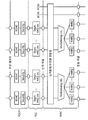
- FIG. 5 shows a structure of a second layer of a base station for multiple carriers.
- FIG. 6 shows a structure of a second layer of a terminal for multicarrier.
- FIG. 9 is a flowchart illustrating a transmission power reporting method according to an embodiment of the present invention.
- FIG. 10 is a block diagram illustrating a wireless device in which an embodiment of the present invention is implemented.
- E-UTRAN Evolved-UMTS Terrestrial Radio Access Network
- LTE Long Term Evolution
- the E-UTRAN includes a base station (BS) 20 that provides a control plane and a user plane to a user equipment (UE).
- the terminal 10 may be fixed or mobile and may be called by other terms such as a mobile station (MS), a user terminal (UT), a subscriber station (SS), a mobile terminal (MT), a wireless device (Wireless Device), and the like.
- the base station 20 refers to a fixed station communicating with the terminal 10, and may be referred to by other terms such as an evolved-NodeB (eNB), a base transceiver system (BTS), an access point, and the like.
- eNB evolved-NodeB
- BTS base transceiver system
- access point and the like.
- the base stations 20 may be connected to each other through an X2 interface.
- the base station 20 is connected to a Serving Gateway (S-GW) through an MME (Mobility Management Entity) and an S1-U through an Evolved Packet Core (EPC) 30, more specifically, an S1-MME through an S1 interface.
- S-GW Serving Gateway
- MME Mobility Management Entity
- EPC Evolved Packet Core
- EPC 30 is composed of MME, S-GW and P-GW (Packet Data Network-Gateway).
- the MME has information about the access information of the terminal or the capability of the terminal, and this information is mainly used for mobility management of the terminal.
- S-GW is a gateway having an E-UTRAN as an endpoint
- P-GW is a gateway having a PDN as an endpoint.
- Layers of the Radio Interface Protocol between the terminal and the network are based on the lower three layers of the Open System Interconnection (OSI) reference model, which is widely known in communication systems.
- L2 second layer
- L3 third layer
- the RRC Radio Resource Control
- the RRC layer located in the third layer plays a role of controlling radio resources between the terminal and the network. To this end, the RRC layer exchanges an RRC message between the terminal and the base station.
- FIG. 2 is a block diagram illustrating a radio protocol architecture for a user plane.
- 3 is a block diagram illustrating a radio protocol structure for a control plane.
- the data plane is a protocol stack for user data transmission
- the control plane is a protocol stack for control signal transmission.
- a physical layer (PHY) layer provides an information transfer service to a higher layer using a physical channel.
- the physical layer is connected to a medium access control (MAC) layer, which is an upper layer, through a transport channel. Data is moved between the MAC layer and the physical layer through the transport channel. Transport channels are classified according to how and with what characteristics data is transmitted over the air interface.
- MAC medium access control
- the physical channel may be modulated by an orthogonal frequency division multiplexing (OFDM) scheme and utilizes time and frequency as radio resources.
- OFDM orthogonal frequency division multiplexing
- the functions of the MAC layer include mapping between logical channels and transport channels and multiplexing / demultiplexing into transport blocks provided as physical channels on transport channels of MAC service data units (SDUs) belonging to the logical channels.
- the MAC layer provides a service to a Radio Link Control (RLC) layer through a logical channel.
- RLC Radio Link Control
- RLC layer Functions of the RLC layer include concatenation, segmentation, and reassembly of RLC SDUs.
- QoS Quality of Service
- the RLC layer has a transparent mode (TM), an unacknowledged mode (UM), and an acknowledged mode (Acknowledged Mode).
- TM transparent mode
- UM unacknowledged mode
- Acknowledged Mode acknowledged mode
- AM Three modes of operation (AM).
- AM RLC provides error correction through an automatic repeat request (ARQ).
- PDCP Packet Data Convergence Protocol
- Functions of the Packet Data Convergence Protocol (PDCP) layer in the user plane include delivery of user data, header compression, and ciphering.
- the functionality of the Packet Data Convergence Protocol (PDCP) layer in the user plane includes the transfer of control plane data and encryption / integrity protection.
- the RRC (Radio Resource Control) layer is defined only in the control plane.
- the RRC layer is responsible for the control of logical channels, transport channels, and physical channels in connection with configuration, re-configuration, and release of radio bearers.
- RB means a logical path provided by the first layer (PHY layer) and the second layer (MAC layer, RLC layer, PDCP layer) for data transmission between the terminal and the network.
- the establishment of the RB means a process of defining characteristics of a radio protocol layer and a channel to provide a specific service, and setting each specific parameter and operation method.
- RB can be further divided into SRB (Signaling RB) and DRB (Data RB).
- SRB is used as a path for transmitting RRC messages in the control plane
- DRB is used as a path for transmitting user data in the user plane.
- the UE If an RRC connection is established between the RRC layer of the UE and the RRC layer of the E-UTRAN, the UE is in an RRC connected state (or referred to as an RRC connected mode), otherwise the RRC idle ( RRC idle) (or RRC idle mode).
- the downlink transmission channel for transmitting data from the network to the UE includes a BCH (Broadcast Channel) for transmitting system information and a downlink shared channel (SCH) for transmitting user traffic or control messages.
- Traffic or control messages of a downlink multicast or broadcast service may be transmitted through a downlink SCH or may be transmitted through a separate downlink multicast channel (MCH).
- the uplink transport channel for transmitting data from the terminal to the network includes a random access channel (RACH) for transmitting an initial control message and an uplink shared channel (SCH) for transmitting user traffic or control messages.
- RACH random access channel
- SCH uplink shared channel
- BCCH broadcast control channel
- PCCH paging control channel
- CCCH common control channel
- MCCH multicast control channel
- MTCH multicast traffic
- the 3GPP LTE system supports a case where the downlink bandwidth and the uplink bandwidth are set differently, but this assumes one component carrier (CC).
- CC is defined as the center frequency (band frequency) and bandwidth. This means that 3GPP LTE is supported only when the bandwidth of the downlink and the bandwidth of the uplink are the same or different in the situation where one CC is defined for the downlink and the uplink, respectively.
- the 3GPP LTE system supports up to 20MHz and may be different in uplink bandwidth and downlink bandwidth, but only one CC is supported in the uplink and the downlink.
- Spectrum aggregation (or bandwidth aggregation, also known as carrier aggregation) supports a plurality of CCs.
- Spectral aggregation is introduced to support increased throughput, to prevent cost increases due to the introduction of wideband radio frequency (RF) devices, and to ensure compatibility with existing systems.
- RF radio frequency
- CC 4 shows an example of a multi-carrier.
- the bandwidth or number of CCs is only an example. Each CC may have a different bandwidth.
- the number of downlink CCs and the number of uplink CCs may be the same or different.
- 5 shows a structure of a second layer of a base station for multiple carriers.
- 6 shows a structure of a second layer of a terminal for multicarrier.
- the MAC layer may manage one or more CCs.
- One MAC layer includes one or more HARQ entities.
- One HARQ entity performs HARQ for one CC.
- Each HARQ entity independently processes a transport block on a transport channel. Accordingly, the plurality of HARQ entities may transmit or receive a plurality of transport blocks through the plurality of CCs.
- One CC (or CC pair of downlink CC and uplink CC) may correspond to one cell.
- each downlink CC may correspond to one serving cell.
- the terminal When a terminal receives a service through a plurality of downlink CCs, the terminal may be said to receive a service from a plurality of serving cells.
- the serving cell may be divided into a primary cell and a secondary cell.
- the primary cell is a cell that operates at the primary frequency and performs an initial connection establishment process, which is a terminal, initiates a connection reestablishment process, or is designated as a primary cell in a handover process.
- the primary cell is also called a reference cell.
- the secondary cell operates at the secondary frequency, can be established after the RRC connection is established, and can be used to provide additional radio resources. At least one primary cell is always configured, and the secondary cell may be added / modified / released by higher layer signaling (eg, RRC message).
- the transmission power of the terminal In order to mitigate interference due to uplink transmission, the transmission power of the terminal needs to be adjusted. If the transmission power of the terminal is too low, it is difficult for the base station to receive uplink data. If the transmission power of the terminal is too high, uplink transmission may cause too much interference in the transmission of other terminals.
- the power headroom reporting process is used to provide the serving base station with information about the difference between the nominal terminal maximum transmit power and the estimated power for UL-SCH transmission.
- the RRC sets two timers (ie, periodic and prohibit timers), and a path for setting a change in the measured downlink pathloss. Power headroom reporting is controlled by sending a loss threshold.
- Power headroom can be defined as the extra power available in addition to the current transmit power.
- the power headroom may be expressed as a difference between the set maximum transmission power and the current transmission power.
- P CMAX is the maximum transmission power of the terminal
- M PUSCH (i) is the bandwidth of the PUSCH resource allocation represented by the number of resource blocks in subframe i,
- PL is the downlink path loss estimate calculated by the terminal
- P O_PUSCH (j), (j), TF (j) and f (i) are parameters given from the higher layer signal.
- Power headroom report Triggered when one of the following events occurs.
- the UE obtains a power headroom value from the physical layer and transmits a PHR MAC CE (Control Element) based on the power headroom value.
- the terminal starts or restarts the periodic timer.
- Power headroom is transmitted as MAC CE.
- the power headroom field in the MAC CE includes 6 bits.
- the set maximum transmit power P CMAX of the terminal is obtained by applying MPR (Maximum Power Reduction) to the uplink transmit power P EMAX of the terminal.
- MPR Maximum Power Reduction
- the MPR may be referred to as a maximum lower limit value of a maximum output power defined in order for the UE to perform power reduction by itself.
- the UE may transmit a signal to the base station after reducing the power within a value allowed by the MPR.
- MPR increases the difference between the average power and the maximum power due to higher order modulation techniques such as 16-QAM and a large number of allocated resource blocks (RBs), thereby overcoming low power efficiency and designing the power amplifier of the terminal. It is introduced to facilitate.
- MPR according to modulation scheme and resource block is defined as follows.
- the terminal subtracts the transmission power to be used currently from the set maximum transmission power to which the MPR is applied, and then calculates the power power headroom in consideration of other factors such as path loss.
- the current transmission power to be used is calculated in consideration of the resource block and the modulation scheme of the allocated uplink resources.
- the terminal may reduce the transmission power by arbitrarily applying the MPR according to the terminal implementation. That is, the base station cannot know the MPR value applied by the terminal, which means that the base station cannot accurately determine the maximum output power of the terminal. Accordingly, the base station can derive how much power the terminal has reduced according to the transmission power allocated to the terminal based on the power headroom.
- the base station may not correctly estimate the transmission power of the terminal.
- the terminal has two serving cells, but the number of serving cells is not limited.
- the maximum output power of the terminal the maximum output power of the terminal for the serving cell 1, and the maximum output power of the terminal for the serving cell 2 are all equal.
- subframe i terms are defined as follows.
- P c transmit power used by the UE for uplink transmission in the serving cell c
- PH UE extra transmission power minus the uplink transmission power for each serving cell from the maximum output power of the terminal
- P SD, c If the transmission power requested by the base station is greater than the power that can be transmitted by the terminal, the amount of power reduced to transmit below the power that can be transmitted by the terminal.
- the terminal Since the sum of the transmit powers P 1 + P 2 for the two serving cells is smaller than the maximum output power of the terminal, the terminal has an extra transmit power PH UE .
- the terminal determines the power headroom PH 1 , PH 2 in consideration of the transmission power (P * 1 and P * 2 ) requested by the base station to the terminal.
- the values of the power headroom PH 1 and PH 2 reported according to the taken MPR of the terminal are the same, but the extra transmission power of the actual terminal is different. That is, in the example of FIG. 7, the terminal has extra power, but in the example of FIG. 8, there is no extra power.
- the extended PHR includes a power headroom PH C for serving cell c and a set maximum transmit power P CMAX, c for serving cell c.
- the present invention proposes a method of triggering and reporting the set maximum transmit power P CMAX, c .
- the condition for triggering the report of the transmit power may be set independently of the condition for triggering the PHR.
- the terminal may trigger a PHR. That is, the MAC CE for the PHR may include P cmax, c .
- the terminal may transmit a scheduling request to the base station. If there is no Physical Uplink Control Channel (PUCCH) resource for the scheduling request, the UE may initiate a random access procedure.
- PUCCH Physical Uplink Control Channel
- the terminal may report the maximum transmission power set using the allocated uplink resources to the base station.
- FIG. 9 is a flowchart illustrating a transmission power reporting method according to an embodiment of the present invention.
- the terminal determines the maximum transmit power P cmax, c set for each serving cell based on the transmit power and the MPR set by the base station (S910).
- the terminal may also determine the power headroom based on the set maximum transmission power.
- the terminal determines whether the reporting of the set maximum transmission power is triggered (S920).
- the triggering condition may be at least one of the following.
- the base station can be set to the reporting configuration for reporting the P cmax, c, or reset, P cmax, c report trigger.
- the base station may set / reset the report setting in units of a serving cell or a terminal.
- the reporting setting may include information about a timer (prohibit timer, periodic timer) and / or threshold. Report configuration may be transmitted to the base station by the base station through the RRC message or MAC message.
- a second condition when P cmax, c is changed to a threshold value or more after the last transmitted P cmax, c , P cmax, c report may be triggered.
- the triggering condition may be limited to the case where the terminal is allocated an uplink radio resource.
- P cmax, c is changed beyond the threshold after P cmax, c last transmitted by the UE, and a new uplink radio resource is allocated, P cmax, c report may be triggered.
- a prohibit timer can be used as a third condition.
- the prohibit timer starts when the P cmax, c report is triggered.
- P cmax, c reporting is prohibited while the prohibit timer is running.
- P cmax, c reporting may be triggered when P cmax, c has changed beyond the threshold since the last transmission P cmax, c .
- a periodic timer can be used as a fourth condition.
- the periodic timer starts when the P cmax, c report is triggered.
- P cmax, c reporting may be triggered when the period timer expires.
- P cmax, c report may be triggered. If the transmission power requested by the base station is greater than the maximum output power of the terminal, the terminal transmits the transmission power requested by the base station lower than the maximum transmission power of the terminal for each serving cell, in which case, the terminal is limited power This is the situation you should use. Or, if the sum of the transmission powers requested by the base station for each serving cell is greater than the maximum transmission power of the terminal, there is a situation in which the terminal should use power on a limited basis. This is because the terminal transmits the sum of the transmission powers requested by the base station for each serving cell lower than the maximum transmission power of the terminal.
- P cmax, c report may be triggered. This is because if the transmission power is determined according to the new uplink resource, P cmax, c may vary.
- the terminal When the reporting of the set maximum transmission power is triggered, the terminal reports a report message including the set maximum transmission power P cmax, c to the base station (S930).
- the report message may further include power headroom.
- the report message may be transmitted as a MAC CE.
- the terminal may transmit a scheduling request or initiate a random access procedure.
- the base station can grasp the transmission power set by the terminal at a desired time.
- more accurate uplink power control is possible, and interference between terminals can be mitigated in uplink transmission.
- FIG. 10 is a block diagram illustrating a wireless device in which an embodiment of the present invention is implemented. This device may implement the operation of the terminal in the embodiment of FIG.
- the terminal 50 includes a processor 51, a memory 52, and an RF unit 53.
- the memory 52 is connected to the processor 51 and stores various information for driving the processor 51.
- the RF unit 53 is connected to the processor 51 and transmits and / or receives a radio signal.
- the processor 51 implements the proposed functions, processes and / or methods. In the embodiment of FIG. 9, the operation of the terminal may be implemented by the processor 51.
- the processor may include application-specific integrated circuits (ASICs), other chipsets, logic circuits, and / or data processing devices.
- the memory may include read-only memory (ROM), random access memory (RAM), flash memory, memory card, storage medium and / or other storage device.
- the RF unit may include a baseband circuit for processing a radio signal.
- the above-described technique may be implemented as a module (process, function, etc.) for performing the above-described function.
- the module may be stored in memory and executed by a processor.
- the memory may be internal or external to the processor and may be coupled to the processor by various well known means.
Abstract
전송 파워를 보고하는 방법 및 장치가 제공된다. 단말은 기지국에 의해 설정된 전송 파워와 MPR(Maximum Power Reduction)을 기반으로 설정된 최대 전송 파워를 결정하고, 상기 설정된 최대 전송 파워의 보고가 트리거링되는지 여부를 결정한다. 상기 단말은 상기 설정된 최대 전송 파워의 보고가 트리거링되면, 상기 설정된 최대 전송파워를 포함하는 보고 메시지를 상기 기지국으로 전송한다.
Description
본 발명은 무선통신에 관한 것으로, 보다 상세하게는 무선통신 시스템에서 단말의 전송 파워를 보고하는 방법 및 장치에 관한 것이다.
UMTS(Universal Mobile Telecommunications System)의 향상인 3GPP(3rd Generation Partnership Project) LTE(long term evolution)는 3GPP 릴리이즈(release) 8로 소개되고 있다. 3GPP LTE는 하향링크에서 OFDMA(orthogonal frequency division multiple access)를 사용하고, 상향링크에서 SC-FDMA(Single Carrier-frequency division multiple access)를 사용한다. 최대 4개의 안테나를 갖는 MIMO(multiple input multiple output)를 채용한다. 최근에는 3GPP LTE의 진화인 3GPP LTE-A(LTE-Advanced)에 대한 논의가 진행 중이다.
상향링크 전송으로 인한 간섭을 완화하기 위해, 단말의 전송 파워가 조절될 필요가 있다. 단말의 전송 파워가 너무 낮으면, 기지국이 상향링크 데이터를 수신하기 어렵다. 단말의 전송 파워가 너무 높으면, 상향링크 전송이 다른 단말의 전송에 너무 많은 간섭을 야기할 수 있다.
단말의 상향링크 전송 파워를 파악하기 위해, 단말은 기지국으로 파워 헤드룸을 보고한다. 하지만, 파워 헤드룸은 최대 전송 파워와 사용될 전송 파워의 차이에 불과하여, 단말이 임의로 전송 파워를 제한할 경우 기지국이 단말의 가용 전송 파워를 정확히 파악하지 못할 수 있다.
본 발명은 전송 파워의 보고가 트리거링되고, 트리거링된 전송 파워를 보고하는 방법 및 장치를 제공한다.
일 양태에서, 무선 통신 시스템에서 단말의 전송 파워 보고 방법이 제공된다. 상기 방법은 기지국에 의해 설정된 전송 파워와 MPR(Maximum Power Reduction)을 기반으로 설정된 최대 전송 파워를 결정하는 단계, 상기 설정된 최대 전송 파워의 보고가 트리거링되는지 여부를 결정하는 단계, 및 상기 설정된 최대 전송 파워의 보고가 트리거링되면, 상기 설정된 최대 전송파워를 포함하는 보고 메시지를 상기 기지국으로 전송하는 단계를 포함한다.
상기 방법은 상기 설정된 최대 전송 파워와 상향링크 전송에 사용할 전송 파워 간의 차이인 파워 헤드룸을 결정하는 단계를 더 포함할 수 있고, 상기 보고 메시지는 상기 파워 헤드룸을 더 포함할 수 있다.
상기 설정된 최대 전송 파워의 보고가 설정 또는 재설정될 때, 상기 설정된 최대 전송 파워의 보고가 트리거링될 수 있다.
마지막으로 보고한 설정된 최대 전송 파워 이후에 상기 설정된 최대 전송 파워가 임계치 이상 변경될 때, 상기 설정된 최대 전송 파워의 보고가 트리거링될 수 있다.
금지 타이머가 만료된 이후 상기 설정된 최대 전송 파워가 임계치 이상 변경될 때, 상기 설정된 최대 전송 파워의 보고가 트리거링되며, 상기 금지 타이머는 상기 설정된 최대 전송 파워의 보고가 트리거링될 때 개시될 수 있다.
주기 타이머가 만료될 때 상기 설정된 최대 전송 파워의 보고가 트리거링되며, 상기 주기 타이머는 상기 설정된 최대 전송 파워의 보고가 트리거링될 때 개시될 수 있다.
전송 파워의 제한적 사용이 검출될 때 상기 설정된 최대 전송 파워의 보고가 트리거링될 수 있다.
할당된 상향링크 자원이 있을 때 상기 설정된 최대 전송 파워의 보고가 트리거링될 수 있다.
다른 양태에서, 무선 통신 시스템에서 전송 파워를 보고하는 단말은 무선 신호를 송신 및 수신하는 RF부, 및 상기 RF부와 연결되는 프로세서를 포함하되, 상기 프로세서는 기지국에 의해 설정된 전송 파워와 MPR(Maximum Power Reduction)을 기반으로 설정된 최대 전송 파워를 결정하고, 상기 설정된 최대 전송 파워의 보고가 트리거링되는지 여부를 결정하고, 및 상기 설정된 최대 전송 파워의 보고가 트리거링되면, 상기 설정된 최대 전송파워를 포함하는 보고 메시지를 상기 기지국으로 전송한다.
기지국이 단말의 전송 파워를 보다 정확히 파악하여, 정교한 상향링크 파워 제어가 가능하고, 단말간 간섭을 완화시킬 수 있다.
도 1은 본 발명이 적용되는 무선통신 시스템을 나타낸다.
도 2는 사용자 평면에 대한 무선 프로토콜 구조를 나타낸 블록도이다.
도 3은 제어 평면에 대한 무선 프로토콜 구조를 나타낸 블록도이다.
도 4는 다중 반송파의 일 예를 나타낸다.
도 5는 다중 반송파를 위한 기지국의 제2 계층의 구조를 나타낸다.
도 6은 다중 반송파를 위한 단말의 제2 계층의 구조를 나타낸다.
도 7은 파워 헤드룸 보고의 일 예를 나타낸다.
도 8은 파워 헤드룸 보고로 인한 문제점의 일 예를 나타낸다
도 9는 본 발명의 일 실시예에 따른 전송 파워 보고 방법을 나타낸 흐름도이다.
도 10은 본 발명의 실시예가 구현되는 무선 장치를 나타낸 블록도이다.
도 1은 본 발명이 적용되는 무선통신 시스템을 나타낸다. 이는 E-UTRAN(Evolved-UMTS Terrestrial Radio Access Network), 또는 LTE(Long Term Evolution)/LTE-A 시스템이라고도 불릴 수 있다.
E-UTRAN은 단말(10; User Equipment, UE)에게 제어 평면(control plane)과 사용자 평면(user plane)을 제공하는 기지국(20; Base Station, BS)을 포함한다. 단말(10)은 고정되거나 이동성을 가질 수 있으며, MS(Mobile station), UT(User Terminal), SS(Subscriber Station), MT(mobile terminal), 무선기기(Wireless Device) 등 다른 용어로 불릴 수 있다. 기지국(20)은 단말(10)과 통신하는 고정된 지점(fixed station)을 말하며, eNB(evolved-NodeB), BTS(Base Transceiver System), 액세스 포인트(Access Point) 등 다른 용어로 불릴 수 있다.
기지국(20)들은 X2 인터페이스를 통하여 서로 연결될 수 있다. 기지국(20)은 S1 인터페이스를 통해 EPC(Evolved Packet Core, 30), 보다 상세하게는 S1-MME를 통해 MME(Mobility Management Entity)와 S1-U를 통해 S-GW(Serving Gateway)와 연결된다.
EPC(30)는 MME, S-GW 및 P-GW(Packet Data Network-Gateway)로 구성된다. MME는 단말의 접속 정보나 단말의 능력에 관한 정보를 가지고 있으며, 이러한 정보는 단말의 이동성 관리에 주로 사용된다. S-GW는 E-UTRAN을 종단점으로 갖는 게이트웨이이며, P-GW는 PDN을 종단점으로 갖는 게이트웨이이다.
단말과 네트워크 사이의 무선인터페이스 프로토콜(Radio Interface Protocol)의 계층들은 통신시스템에서 널리 알려진 개방형 시스템간 상호접속 (Open System Interconnection; OSI) 기준 모델의 하위 3개 계층을 바탕으로 L1 (제1계층), L2 (제2계층), L3(제3계층)로 구분될 수 있는데, 이 중에서 제1계층에 속하는 물리계층은 물리채널(Physical Channel)을 이용한 정보전송서비스(Information Transfer Service)를 제공하며, 제 3계층에 위치하는 RRC(Radio Resource Control) 계층은 단말과 네트워크 간에 무선자원을 제어하는 역할을 수행한다. 이를 위해 RRC 계층은 단말과 기지국간 RRC 메시지를 교환한다.
도 2는 사용자 평면(user plane)에 대한 무선 프로토콜 구조(radio protocol architecture)를 나타낸 블록도이다. 도 3은 제어 평면(control plane)에 대한 무선 프로토콜 구조를 나타낸 블록도이다. 데이터 평면은 사용자 데이터 전송을 위한 프로토콜 스택(protocol stack)이고, 제어 평면은 제어신호 전송을 위한 프로토콜 스택이다.
도 2 및 3을 참조하면, 물리계층(PHY(physical) layer)은 물리채널(physical channel)을 이용하여 상위 계층에게 정보 전송 서비스(information transfer service)를 제공한다. 물리계층은 상위 계층인 MAC(Medium Access Control) 계층과는 전송채널(transport channel)을 통해 연결되어 있다. 전송채널을 통해 MAC 계층과 물리계층 사이로 데이터가 이동한다. 전송채널은 무선 인터페이스를 통해 데이터가 어떻게 어떤 특징으로 전송되는가에 따라 분류된다.
서로 다른 물리계층 사이, 즉 송신기와 수신기의 물리계층 사이는 물리채널을 통해 데이터가 이동한다. 상기 물리채널은 OFDM(Orthogonal Frequency Division Multiplexing) 방식으로 변조될 수 있고, 시간과 주파수를 무선자원으로 활용한다.
MAC 계층의 기능은 논리채널과 전송채널간의 맵핑 및 논리채널에 속하는 MAC SDU(service data unit)의 전송채널 상으로 물리채널로 제공되는 전송블록(transport block)으로의 다중화/역다중화를 포함한다. MAC 계층은 논리채널을 통해 RLC(Radio Link Control) 계층에게 서비스를 제공한다.
RLC 계층의 기능은 RLC SDU의 연결(concatenation), 분할(segmentation) 및 재결합(reassembly)를 포함한다. 무선베어러(Radio Bearer; RB)가 요구하는 다양한 QoS(Quality of Service)를 보장하기 위해, RLC 계층은 투명모드(Transparent Mode, TM), 비확인 모드(Unacknowledged Mode, UM) 및 확인모드(Acknowledged Mode, AM)의 세 가지의 동작모드를 제공한다. AM RLC는 ARQ(automatic repeat request)를 통해 오류 정정을 제공한다.
사용자 평면에서의 PDCP(Packet Data Convergence Protocol) 계층의 기능은 사용자 데이터의 전달, 헤더 압축(header compression) 및 암호화(ciphering)를 포함한다. 사용자 평면에서의 PDCP(Packet Data Convergence Protocol) 계층의 기능은 제어 평면 데이터의 전달 및 암호화/무결정 보호(integrity protection)를 포함한다.
RRC(Radio Resource Control) 계층은 제어 평면에서만 정의된다. RRC 계층은 무선 베어러들의 설정(configuration), 재설정(re-configuration) 및 해제(release)와 관련되어 논리채널, 전송채널 및 물리채널들의 제어를 담당한다. RB는 단말과 네트워크간의 데이터 전달을 위해 제1 계층(PHY 계층) 및 제2 계층(MAC 계층, RLC 계층, PDCP 계층)에 의해 제공되는 논리적 경로를 의미한다.
RB가 설정된다는 것은 특정 서비스를 제공하기 위해 무선 프로토콜 계층 및 채널의 특성을 규정하고, 각각의 구체적인 파라미터 및 동작 방법을 설정하는 과정을 의미한다. RB는 다시 SRB(Signaling RB)와 DRB(Data RB) 두가지로 나누어 질 수 있다. SRB는 제어 평면에서 RRC 메시지를 전송하는 통로로 사용되며, DRB는 사용자 평면에서 사용자 데이터를 전송하는 통로로 사용된다.
단말의 RRC 계층과 E-UTRAN의 RRC 계층 사이에 RRC 연결(RRC Connection)이 확립되면, 단말은 RRC 연결(RRC connected) 상태(또는 RRC 연결 모드라 함)에 있게 되고, 그렇지 못할 경우 RRC 아이들(RRC idle) 상태(또는 RRC 아이들 모드라 함)에 있게 된다.
네트워크에서 단말로 데이터를 전송하는 하향링크 전송채널로는 시스템정보를 전송하는 BCH(Broadcast Channel)과 그 이외에 사용자 트래픽이나 제어메시지를 전송하는 하향링크 SCH(Shared Channel)이 있다. 하향링크 멀티캐스트 또는 브로드캐스트 서비스의 트래픽 또는 제어메시지의 경우 하향링크 SCH를 통해 전송될 수도 있고, 또는 별도의 하향링크 MCH(Multicast Channel)을 통해 전송될 수도 있다. 한편, 단말에서 네트워크로 데이터를 전송하는 상향링크 전송채널로는 초기 제어메시지를 전송하는 RACH(Random Access Channel)와 그 이외에 사용자 트래픽이나 제어메시지를 전송하는 상향링크 SCH(Shared Channel)가 있다.
전송채널 상위에 있으며, 전송채널에 매핑되는 논리채널(Logical Channel)로는 BCCH(Broadcast Control Channel), PCCH(Paging Control Channel), CCCH(Common Control Channel), MCCH(Multicast Control Channel), MTCH(Multicast Traffic Channel) 등이 있다.
이제 다중 반송파(multiple carrier) 시스템에 대해 기술한다.
3GPP LTE 시스템은 하향링크 대역폭과 상향링크 대역폭이 다르게 설정되는 경우를 지원하나, 이는 하나의 요소 반송파(component carrier, CC)를 전제한다. CC는 중심 주파수(center frequency)와 대역폭으로 정의된다. 이는 3GPP LTE는 각각 하향링크와 상향링크에 대하여 각각 하나의 CC가 정의되어 있는 상황에서, 하향링크의 대역폭과 상향링크의 대역폭이 같거나 다른 경우에 대해서만 지원되는 것을 의미한다. 예를 들어, 3GPP LTE 시스템은 최대 20MHz을 지원하고, 상향링크 대역폭과 하향링크 대역폭을 다를 수 있지만, 상향링크와 하향링크에 하나의 CC 만을 지원한다.
스펙트럼 집성(spectrum aggregation)(또는, 대역폭 집성(bandwidth aggregation), 반송파 집성(carrier aggregation)이라고도 함)은 복수의 CC를 지원하는 것이다. 스펙트럼 집성은 증가되는 수율(throughput)을 지원하고, 광대역 RF(radio frequency) 소자의 도입으로 인한 비용 증가를 방지하고, 기존 시스템과의 호환성을 보장하기 위해 도입되는 것이다.
도 4는 다중 반송파의 일 예를 나타낸다. 5개의 CC(CC #1, CC #2, CC #3, CC #4, CC #5)가 있고, 각 CC는 20 MHz의 대역폭을 가진다. 따라서, 20MHz 대역폭을 갖는 CC 단위의 그래뉼래리티(granularity)로서 5개의 CC가 할당된다면, 최대 100Mhz의 대역폭을 지원할 수 있는 것이다.
CC의 대역폭이나 개수는 예시에 불과하다. 각 CC는 서로 다른 대역폭을 가질 수 있다. 하향링크 CC의 수와 상향링크 CC의 수는 동일할 수도, 서로 다를 수도 있다.
도 5는 다중 반송파를 위한 기지국의 제2 계층의 구조를 나타낸다. 도 6은 다중 반송파를 위한 단말의 제2 계층의 구조를 나타낸다.
MAC 계층은 하나 또는 그 이상의 CC를 관리할 수 있다. 하나의 MAC 계층은 하나 또는 그 이상의 HARQ 개체(entity)를 포함한다. 하나의 HARQ 개체는 하나의 CC에 대한 HARQ를 수행한다. 각 HARQ 개체는 독립적으로 전송 채널 상으로 전송 블록(transport block)을 처리한다. 따라서, 복수의 CC를 통해 복수의 HARQ 개체는 복수의 전송 블록을 전송 또는 수신할 수 있다.
하나의 CC(또는 하향링크 CC와 상향링크 CC의 CC 쌍(pair))는 하나의 셀에 대응될 수 있다. 각 하향링크 CC를 통해 동기 신호와 시스템 정보가 제공되면, 각 하향링크 CC이 하나의 서빙 셀에 대응된다고 할 수 있다. 단말이 복수의 하향링크 CC를 통해 서비스를 제공받으면, 단말은 복수의 서빙 셀로부터 서비스를 제공받는다고 할 수 있다.
서빙 셀은 1차 셀(primary cell)과 2차 셀(secondary cell)로 구분될 수 있다. 1차 셀은 1차 주파수에서 동작하고, 단말인 초기 연결 확립 과정을 수행하거나, 연결 재확립 과정을 개시하거나, 핸드오버 과정에서 1차셀로 지정된 셀이다. 1차 셀은 기준 셀(reference cell)이라고도 한다. 2차 셀은 2차 주파수에서 동작하고, RRC 연결이 확립된 후에 설정될 수 있으며, 추가적인 무선 자원을 제공하는데 사용될 수 있다. 항상 적어도 하나의 1차 셀이 설정되고, 2차 셀은 상위 계층 시그널링(예, RRC 메시지)에 의해 추가/수정/해제될 수 있다.
이제 파워 헤드룸(power headroom) 보고에 대해 기술한다.
상향링크 전송으로 인한 간섭을 완화하기 위해, 단말의 전송 파워가 조절될 필요가 있다. 단말의 전송 파워가 너무 낮으면, 기지국이 상향링크 데이터를 수신하기 어렵다. 단말의 전송 파워가 너무 높으면, 상향링크 전송이 다른 단말의 전송에 너무 많은 간섭을 야기할 수 있다.
파워 헤드룸 보고 과정은 서빙 기지국에 명목상의 단말 최대 전송 파워와 UL-SCH 전송을 위한 추정 파워간의 차이에 관한 정보를 제공하는데 사용된다. 파워 헤드룸 보고를 트리거링하기 위해 RRC는 2개의 타이머(즉, 주기 타이머(periodic timer)와 금지 타이머(prohibit timer))를 설정하고, 측정된 하향링크 경로손실(pathloss) 의 변화값을 설정하는 경로손실 임계치를 보내줌으로써 파워 헤드룸 보고를 제어한다.
파워 헤드룸은 현재 전송 파워 다 추가적으로 더 사용할 수 있는 여분의 파워로 정의될 수 있다. 파워 헤드룸은 설정된 최대 전송 파워와 현재 전송 파워의 차이로 나타낼 수 있다.
3GPP TS 36.213 V8.8.0 (2009-09) "Evolved Universal Terrestrial Radio Access (E-UTRA); Physical layer procedures (Release 8)"의 5.1.1절에 의하면, 서브프레임 i에 대한 파워 헤드룸 PH(i)는 다음과 같이 정의될 수 있다.
수학식 1 
여기서,
PCMAX 는 단말의 설정된 최대 전송 파워,
MPUSCH(i)는 서브프레임 i에서 자원블록의 수로 나타내는 PUSCH 자원 할당의 대역폭,
PL은 단말이 계산한 하향링크 경로손실 추정값,
PO_PUSCH(j),  (j),
(j),  TF(j) 및 f(i)는 상위계층 신호로부터 주어지는 파라미터들이다.
파워 헤드룸 보고(power headroom report, PHR) 다음 중 하나의 이벤트가 발생하면 트리거된다.
- 단말이 새로운 전송을 위한 상향링크 자원을 가지고, PHR 전송 이후 경로손실이 임계치 이상 바뀌거나, 금지 타이머가 만료된 경우
- 주기 타이머가 만료된 경우
- PHR 기능이 설정 또는 재설정된 경우
단말은 이번 TTI에 새로운 전송을 위해 할당된 상향링크 자원이 있다면, 물리계층으로부터 파워 헤드룸 값을 획득하고, 상기 파워 헤드룸 값을 기반으로 PHR MAC CE(Control Element)를 전송한다. 단말은 주기 타이머를 시작 또는 재시작한다.
파워 헤드룸은 MAC CE로써 전송된다. MAC CE 내의 파워 헤드룸 필드는 6비트를 포함한다.
단말의 설정된 최대 전송 파워 PCMAX는 기지국에 의해 주어지는 단말의 상향링크 전송 파워 PEMAX에 MPR(Maximum Power Reduction)을 적용하여 구한다. 즉, PCMAX<(PEMAX-MPR) 이다.
MPR은 단말이 전력 감소를 자체적으로 수행할 수 있도록 하기 위해 정의된 최대 출력 전력(maximum output power)의 최대 하한 값이라 할 수 있다. 단말은 자체적으로 MPR이 허락하는 값 내에서 전력을 감소시킨 후 기지국으로 신호를 전송할 수 있다. MPR은 16-QAM과 같은 고차 변조 기법과 많은 수의 할당된 자원 블록(resource block, RB)으로 인해 평균 파워와 최대 파워의 차이가 커지고, 이로 인한 낮은 파워 효율을 극복하고, 단말의 파워 증폭기 설계를 용이하게 하기 위해 도입된 것이다.
3GPP TS 36.101 V8.7.0 (2009-09)의 6.2절에 의하면, 변조 방식과 자원 블록에 따른 MPR을 다음과 같이 정의하고 있다.
표 1
| 변조방식 | 채널 대역폭 (RB) | MPR (dB) | |||||
| 1.4MHz | 3MHz | 5MHz | 10MHz | 15MHz | 20MHz | ||
| QPSK | >5 | >4 | >8 | >12 | >16 | >18 | ≤1 |
| 16-QAM | ≤5 | ≤4 | ≤8 | ≤12 | ≤16 | ≤18 | ≤1 |
| 16-QAM | >5 | >4 | >8 | >12 | >16 | >18 | ≤2 |
상술한 바와 같이, 단말은 MPR을 적용한 설정된 최대 전송 파워에 현재 사용할 전송파워를 뺀 후, 추가적으로 경로손실과 같은 다른 요소들을 고려하여 파워 파워 헤드룸을 계산한다. 상기 현재 사용할 전송 파워는 할당된 상향링크 자원의 자원 블록과 변조 방식을 고려하여 계산된다.
단말은 단말 구현에 따라 MPR을 임의대로 적용하여 전송 파워를 감소시킬 수 있다. 즉, 기지국은 단말이 적용한 MPR 값을 알 수 없고, 이는 기지국이 단말의 최대 출력 파워를 정확히 판단할 수 없다는 것을 의미한다. 따라서, 기지국은 자신이 단말에게 할당한 전송 파워에 따라 단말이 얼마만큼의 전력을 감소시켰는지를 파워 헤드룸을 기반으로 도출할 수 있다.
하지만, 복수의 서빙 셀이 도입됨에 따라 단말이 단지 파워 헤드룸을 보고하면, 기지국이 올바르게 단말의 전송 파워를 추정하지 못할 수 있다.
이하에서, 단말은 두 개의 서빙 셀을 가지고 있다고 가정하지만, 서빙 셀의 개수에 제한이 있는 것은 아니다.
설명을 명확히 하기 위해, 단말의 최대 출력 파워, 서빙 셀 1에 대한 단말의 최대 출력 파워, 서빙 셀 2에 대한 단말의 최대 출력 파워가 모두 같다고 한다.
서브프레임 i에서 다음과 같이 용어를 정의한다.
Pc : 서빙 셀 c에서 단말이 상향링크 전송에 사용하는 전송 파워,
PHc : 서빙 셀 c에서 파워 헤드룸,
PHUE : 단말의 최대 출력 파워에서 각 서빙 셀에 대한 상향링크 전송 파워를 뺀 여분의 전송 파워,
P*
c : 서빙 셀 c에 대해 기지국이 단말에게 요청한 전송 파워,
PSD,c: 단말이 전송 가능한 파워 보다 기지국이 요청한 전송 파워가 더 큰 경우, 단말이 전송 가능한 전력 이하로 전송하기 위해 전력을 감소시킨 양.
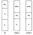
도 7은 파워 헤드룸 보고의 일 예를 나타낸다.
두 서빙 셀에 대해 동일한 값의 파워 헤드룸 PH1, PH2를 결정한다. 그리고, PHR이 트리거링되면, 단말은 PH1, PH2를 기지국으로 보고한다.
두 서빙 셀에 대한 전송 파워 합 P1+P2가 단말의 최대 출력 파워보다 작으므로, 단말은 여분의 전송 파워 PHUE 를 가지고 있다.
도 8은 파워 헤드룸 보고로 인한 문제점의 일 예를 나타낸다.
도 7의 예와 비교하여, 단말의 역량(capability)이 더 우수하여 더 작은 MPR를 취할 수 있다고 하자. 단말은 기지국이 단말에게 요청한 전송 파워 (P*
1 과 P*
2)를 고려하여, 파워 헤드룸 PH1, PH2를 결정한다.
각 서빙 셀에서 기지국이 요청한 전송 파워의 합이 단말의 최대 출력 전력 보다 크기 때문에, 각 서빙 셀에 대해 PSD,1 또는 PSD,2 만큼 전력을 감소시킨 P1과 P2이 실제 전송 파워로 사용된다. 이 경우, 단말의 최대 출력 파워 측면에서 여분의 출력이 남아 있지 않다: PHUE=0.
도 7의 예와 도 8의 예에서, 단말의 취한 MPR에 따라 보고되는 파워 헤드룸 PH1, PH2의 값은 동일하지만, 실제 단말의 여분의 전송 파워는 다르다. 즉, 도 7의 예에서는 단말에게 여분의 파워가 있지만, 도 8의 예에서 여분의 파워가 없다.
이는 파워 헤드룸이 각 서빙 셀에 대해 결정되기 때문이다. 따라서, 각 서빙셀에 대한 파워 헤드룸과 함께 각 서빙 셀에 대한 설정된 최대 전송 파워도 함께 보고하는 것이 제안되고 있다. 확장된 PHR는 서빙 셀 c에 대한 파워 헤드룸 PHC와 서빙 셀 c에 대한 설정된 최대 전송 파워 PCMAX,c를 포함한다.
하지만, 확장된 PHR도 파워 헤드룸이 트리거링될 때만 보고되므로, 기지국이 정확하기 단말의 파워 상태를 판단하기 어렵다.
본 발명에서는 설정된 최대 전송 파워 PCMAX,c를 트리거링하고 보고하는 방법을 제안한다. 상기 전송 파워의 보고를 트리거링하는 조건은 PHR을 트리거링하는 조건과 독립적으로 설정될 수 있다.
설정된 최대 전송 파워의 보고가 트리거 되면, 단말은 PHR을 트리거할 수 있다. 즉, PHR을 위한 MAC CE는 Pcmax,c를 포함할 수 있다.
설정된 최대 전송 파워의 보고가 트리거되어 PHR이 트리거되지만, PHR을 위한 상향링크 무선 자원이 없으면, 단말은 기지국으로 스케줄링 요청을 전송할 수 있다. 만약 스케줄링 요청을 위한 PUCCH(Physical Uplink Control Channel) 자원이 없으면, 단말은 랜덤 액세스 과정을 개시할 수 있다.
스케줄링 요청 또는 랜덤 액세스에 대한 응답으로 상향링크 자원이 할당되면, 단말은 할당된 상향링크 자원을 이용하요 설정된 최대 전송 파워를 기지국으로 보고할 수 있다.
도 9는 본 발명의 일 실시예에 따른 전송 파워 보고 방법을 나타낸 흐름도이다.
단말은 기지국에 의해 설정된 전송 파워와 MPR을 기반으로 각 서빙 셀에 대해 설정된 최대 전송 파워 Pcmax,c를 결정한다(S910). 단말은 또한 상기 설정된 최대 전송 파워을 기반으로 파워 헤드룸을 결정할 수 있다.
단말은 상기 설정된 최대 전송 파워의 보고가 트리거링되는지 여부를 결정한다(S920).
트리거링 조건은 다음 중 적어도 어느 하나일 수 있다.
첫번째 조건으로는, 기지국이 Pcmax,c를 보고하기 위한 보고 설정을 설정하거나 또는 재설정할 때, Pcmax,c 보고가 트리거될 수 있한다. 기지국은 서빙 셀 단위 또는 단말 단위로, 보고 설정을 설정/재설정할 수 있다. 보고 설정은 타이머(금지 타이머, 주기 타이머) 및/또는 임계치에 관한 정보를 포함할 수 있다. 보고 설정은 RRC 메시지 또는 MAC 메시지를 통해 기지국이 단말에게 전송할 수 있다.
두번째 조건으로는, 단말은 마지막으로 전송한 Pcmax,c 이후에 Pcmax,c가 임계치이상으로 변경될 때, Pcmax,c 보고가 트리거될 수 있다. 또한, 트리거링 조건은 단말이 상향링크 무선자원을 할당받은 경우로 한정할 수도 있다. 단말이 마지막으로 전송한 Pcmax,c 이후에 Pcmax,c가 임계치 이상으로 변경되고, 새로운 상향링크 무선자원이 할당될 때, Pcmax,c 보고가 트리거될 수 있다.
세번째 조건으로는, 금지 타이머가 이용될 수 있다. 금지 타이머는 Pcmax,c 보고가 트리거링되면 개시한다. 금지 타이머가 동작 중인 동안 Pcmax,c 보고는 금지된다. 상기 금지 타이머가 만료된 후, 마지막으로 전송한 Pcmax,c 이후로 Pcmax,c가 임계치 이상 변경될 때, Pcmax,c 보고가 트리거될 수 있다.
네번째 조건으로는, 주기 타이머가 이용될 수 있다. 주기 타이머는 Pcmax,c 보고가 트리거링되면 개시한다. 상기 주기 타이머가 만료될 때 Pcmax,c 보고가 트리거될 수 있다.
다섯번째 조건으로는, 단말이 제한적으로 전력을 사용해야 되는 상황이 되면, Pcmax,c 보고가 트리거될 수 있다. 단말의 최대 출력 파워보다 기지국이 요청하는 전송 파워가 큰 경우, 단말은 기지국이 요청하는 전송 파워를 각 서빙 셀에 대한 단말의 최대 전송 파워 이하로 낮춰서 보내게 되는데, 이 경우, 단말은 제한적으로 전력을 사용해야 되는 상황이 된다. 또는, 각 서빙 셀에 대해 기지국이 요청한 전송 파워의 합이 단말의 최대 전송 파워보다 큰 경우, 단말이 제한적으로 전력을 사용해야 되는 상황이 된다. 단말은 각 서빙 셀에 대한 기지국이 요청한 전송 파워의 합을 단말의 최대 전송 파워 이하로 낮춰서 보내게 되기 때문이다.
여섯번째 조건으로, 단말이 새로운 상향링크 자원을 기지국으로부터 할당받으면, Pcmax,c 보고가 트리거될 수 있다. 새로운 상향링크 자원에 따라 전송 파워가 결정되면, Pcmax,c 가 달라질 수 있기 때문이다.
상기 설정된 최대 전송 파워의 보고가 트리거링되면, 단말은 상기 설정된 최대 전송 파워 Pcmax,c 를 포함하는 보고 메시지를 상기 기지국으로 보고한다(S930). 상기 보고 메시지는 파워 헤드룸을 더 포함할 수 있다. 상기 보고 메시지는 MAC CE로써 전송될 수 있다.
상기 설정된 최대 전송 파워의 보고가 트리거링될 때, 보고 메시지를 위한 상향링크 자원이 없으면, 단말은 스케줄링 요청을 전송하거나 또는 랜덤 액세스 과정을 개시할 수 있다.
Pcmax,c의 보고를 위한 트리거링 조건이 제안됨에 따라, 기지국은 원하는 시점에 단말에 의해 설정된 전송 파워를 파악할 수 있다. 따라서, 보다 정확한 상향링크 파워 제어가 가능하고, 상향링크 전송에서 단말 간 간섭을 완화할 수 있다.
도 10은 본 발명의 실시예가 구현되는 무선 장치를 나타낸 블록도이다. 이 장치는 도 9의 실시예에서 단말의 동작을 구현할 수 있다.
단말(50)은 프로세서(processor, 51), 메모리(memory, 52) 및 RF부(RF(radio frequency) unit, 53)을 포함한다. 메모리(52)는 프로세서(51)와 연결되어, 프로세서(51)를 구동하기 위한 다양한 정보를 저장한다. RF부(53)는 프로세서(51)와 연결되어, 무선 신호를 송신 및/또는 수신한다. 프로세서(51)는 제안된 기능, 과정 및/또는 방법을 구현한다. 도 9의 실시예에서 단말의 동작은 프로세서(51)에 의해 구현될 수 있다.
프로세서는 ASIC(application-specific integrated circuit), 다른 칩셋, 논리 회로 및/또는 데이터 처리 장치를 포함할 수 있다. 메모리는 ROM(read-only memory), RAM(random access memory), 플래쉬 메모리, 메모리 카드, 저장 매체 및/또는 다른 저장 장치를 포함할 수 있다. RF부는 무선 신호를 처리하기 위한 베이스밴드 회로를 포함할 수 있다. 실시예가 소프트웨어로 구현될 때, 상술한 기법은 상술한 기능을 수행하는 모듈(과정, 기능 등)로 구현될 수 있다. 모듈은 메모리에 저장되고, 프로세서에 의해 실행될 수 있다. 메모리는 프로세서 내부 또는 외부에 있을 수 있고, 잘 알려진 다양한 수단으로 프로세서와 연결될 수 있다.
상술한 예시적인 시스템에서, 방법들은 일련의 단계 또는 블록으로써 순서도를 기초로 설명되고 있지만, 본 발명은 단계들의 순서에 한정되는 것은 아니며, 어떤 단계는 상술한 바와 다른 단계와 다른 순서로 또는 동시에 발생할 수 있다. 또한, 당업자라면 순서도에 나타낸 단계들이 배타적이지 않고, 다른 단계가 포함되거나 순서도의 하나 또는 그 이상의 단계가 본 발명의 범위에 영향을 미치지 않고 삭제될 수 있음을 이해할 수 있을 것이다.
Claims (15)
- 무선 통신 시스템에서 단말의 전송 파워 보고 방법에 있어서,기지국에 의해 설정된 전송 파워와 MPR(Maximum Power Reduction)을 기반으로 설정된 최대 전송 파워를 결정하는 단계;상기 설정된 최대 전송 파워의 보고가 트리거링되는지 여부를 결정하는 단계; 및상기 설정된 최대 전송 파워의 보고가 트리거링되면, 상기 설정된 최대 전송파워를 포함하는 보고 메시지를 상기 기지국으로 전송하는 단계를 포함하는 전송 파워 보고 방법.
- 제 1 항에 있어서,상기 설정된 최대 전송 파워와 상향링크 전송에 사용할 전송 파워 간의 차이인 파워 헤드룸을 결정하는 단계를 더 포함하고,상기 보고 메시지는 상기 파워 헤드룸을 더 포함하는 것을 특징으로 하는 전송 파워 보고 방법.
- 제 2 항에 있어서,상기 보고 메시지는 MAC(Medium Access Control) CE(Control Element)인 것을 특징으로 하는 전송 파워 보고 방법.
- 제 2 항에 있어서,상기 보고 메시지의 전송을 위한 스케줄링 요청을 상기 기지국으로 전송하는 단계; 및상기 스케줄링 요청에 대한 응답으로 상향링크 자원을 상기 기지국으로부터 수신하는 단계를 더 포함하고,상기 상향링크 자원을 이용하여 상기 보고 메시지가 전송되는 것을 특징으로 하는 전송 파워 보고 방법.
- 제 1 항에 있어서,상기 설정된 최대 전송 파워의 보고가 설정 또는 재설정될 때, 상기 설정된 최대 전송 파워의 보고가 트리거링되는 것을 특징으로 하는 전송 파워 보고 방법.
- 제 1 항에 있어서,마지막으로 보고한 설정된 최대 전송 파워 이후에 상기 설정된 최대 전송 파워가 임계치 이상 변경될 때, 상기 설정된 최대 전송 파워의 보고가 트리거링되는 것을 특징으로 하는 전송 파워 보고 방법.
- 제 1 항에 있어서,금지 타이머가 만료된 이후 상기 설정된 최대 전송 파워가 임계치 이상 변경될 때, 상기 설정된 최대 전송 파워의 보고가 트리거링되며,상기 금지 타이머는 상기 설정된 최대 전송 파워의 보고가 트리거링될 때 개시되는 것을 특징으로 하는 전송 파워 보고 방법.
- 제 1 항에 있어서,주기 타이머가 만료될 때 상기 설정된 최대 전송 파워의 보고가 트리거링되며,상기 주기 타이머는 상기 설정된 최대 전송 파워의 보고가 트리거링될 때 개시되는 것을 특징으로 하는 전송 파워 보고 방법.
- 제 1 항에 있어서,전송 파워의 제한적 사용이 검출될 때 상기 설정된 최대 전송 파워의 보고가 트리거링되는 것을 특징으로 하는 전송 파워 보고 방법.
- 제 1 항에 있어서,할당된 상향링크 자원이 있을 때 상기 설정된 최대 전송 파워의 보고가 트리거링되는 것을 특징으로 하는 전송 파워 보고 방법.
- 무선 통신 시스템에서 전송 파워를 보고하는 단말에 있어서,무선 신호를 송신 및 수신하는 RF부; 및상기 RF부와 연결되는 프로세서를 포함하되, 상기 프로세서는기지국에 의해 설정된 전송 파워와 MPR(Maximum Power Reduction)을 기반으로 설정된 최대 전송 파워를 결정하고,상기 설정된 최대 전송 파워의 보고가 트리거링되는지 여부를 결정하고; 및상기 설정된 최대 전송 파워의 보고가 트리거링되면, 상기 설정된 최대 전송파워를 포함하는 보고 메시지를 상기 기지국으로 전송하는 것을 특징으로 하는 단말.
- 제 11 항에 있어서,상기 프로세서는 상기 설정된 최대 전송 파워와 상향링크 전송에 사용할 전송 파워간의 차이인 파워 헤드룸을 결정하고, 상기 보고 메시지는 상기 파워 헤드룸을 더 포함하는 것을 특징으로 하는 단말.
- 제 11 항에 있어서,상기 설정된 최대 전송 파워의 보고가 설정 또는 재설정될 때, 상기 설정된 최대 전송 파워의 보고가 트리거링되는 것을 특징으로 하는 단말.
- 제 11 항에 있어서,마지막으로 보고한 설정된 최대 전송 파워 이후에 상기 설정된 최대 전송 파워가 임계치 이상 변경될 때, 상기 설정된 최대 전송 파워의 보고가 트리거링되는 것을 특징으로 하는 단말.
- 제 11 항에 있어서,금지 타이머가 만료된 이후 상기 설정된 최대 전송 파워가 임계치 이상 변경될 때, 상기 설정된 최대 전송 파워의 보고가 트리거링되며,상기 금지 타이머는 상기 설정된 최대 전송 파워의 보고가 트리거링될 때 개시되는 것을 특징으로 하는 단말.
Priority Applications (2)
| Application Number | Priority Date | Filing Date | Title |
|---|---|---|---|
| US13/883,607 US9161317B2 (en) | 2010-11-08 | 2011-11-08 | Transmission power reporting method and apparatus |
| CN201180053892.6A CN103201973B (zh) | 2010-11-08 | 2011-11-08 | 传输功率报告方法和装置 |
Applications Claiming Priority (2)
| Application Number | Priority Date | Filing Date | Title |
|---|---|---|---|
| US41144110P | 2010-11-08 | 2010-11-08 | |
| US61/411,441 | 2010-11-08 |
Publications (2)
| Publication Number | Publication Date |
|---|---|
| WO2012064069A2 true WO2012064069A2 (ko) | 2012-05-18 |
| WO2012064069A3 WO2012064069A3 (ko) | 2012-07-12 |
Family
ID=46051394
Family Applications (1)
| Application Number | Title | Priority Date | Filing Date |
|---|---|---|---|
| PCT/KR2011/008444 WO2012064069A2 (ko) | 2010-11-08 | 2011-11-08 | 전송 파워 보고 방법 및 장치 |
Country Status (3)
| Country | Link |
|---|---|
| US (1) | US9161317B2 (ko) |
| CN (1) | CN103201973B (ko) |
| WO (1) | WO2012064069A2 (ko) |
Cited By (1)
| Publication number | Priority date | Publication date | Assignee | Title |
|---|---|---|---|---|
| WO2014109559A1 (en) * | 2013-01-11 | 2014-07-17 | Lg Electronics Inc. | Method for reporting a power headroom and communication device thereof |
Families Citing this family (10)
| Publication number | Priority date | Publication date | Assignee | Title |
|---|---|---|---|---|
| CN102695253B (zh) * | 2011-03-25 | 2016-08-03 | 中兴通讯股份有限公司 | 一种基站节能信息的传递方法及节能实现方法与系统 |
| JP5761450B2 (ja) | 2011-04-29 | 2015-08-12 | 富士通株式会社 | 最大構成出力パワーの報告方法及び端末装置 |
| EP2724480B1 (en) * | 2011-06-21 | 2015-08-19 | Telefonaktiebolaget L M Ericsson (publ) | Selecting uplink multi-antenna transmission to enhance coverage |
| US8644183B2 (en) * | 2012-06-26 | 2014-02-04 | Qualcomm Incorporated | Systems and methods for memory-efficient storage and extraction of maximum power reduction (MPR) values in two-carrier wireless data systems |
| US9609499B2 (en) * | 2013-05-22 | 2017-03-28 | Avago Technologies General Ip (Singapore) Pte. Ltd. | Apparatus and method to prioritize a random access procedure for emergency access |
| US10361833B2 (en) * | 2013-12-11 | 2019-07-23 | Innovative Sonic Corporation | Method and apparatus for improving device to device (D2D) communication in a wireless communication system |
| US9491709B2 (en) * | 2013-12-27 | 2016-11-08 | Qualcomm Incorporated | Apparatus and method for triggering a maximum power reporting event in a wireless communication network |
| EP2919534B1 (en) * | 2014-03-12 | 2019-03-06 | Panasonic Intellectual Property Corporation of America | Power headroom reporting for MTC devices in enhanced coverage mode |
| CN105282783B (zh) * | 2014-07-22 | 2020-03-27 | 中兴通讯股份有限公司 | 一种双连接中功率余量报告的上报方法、装置和系统 |
| WO2022012395A1 (en) * | 2020-07-16 | 2022-01-20 | Guangdong Oppo Mobile Telecommunications Corp., Ltd. | Apparatus and method of wireless communication |
Citations (1)
| Publication number | Priority date | Publication date | Assignee | Title |
|---|---|---|---|---|
| KR20100072242A (ko) * | 2007-10-09 | 2010-06-30 | 텔레포나크티에볼라게트 엘엠 에릭슨(피유비엘) | 원거리 통신 시스템의 방법 및 장치 |
Family Cites Families (15)
| Publication number | Priority date | Publication date | Assignee | Title |
|---|---|---|---|---|
| US6393005B1 (en) * | 1997-06-27 | 2002-05-21 | Nec Corporation | Method of controlling transmitting power of a base station in a CDMA mobile communication system |
| DE69935131T2 (de) * | 1999-06-23 | 2007-11-22 | Sony Deutschland Gmbh | Senderleistungssteuerung für Netzwerkgeräte in einem drahtlosen Netzwerk |
| JP4005400B2 (ja) * | 2002-04-10 | 2007-11-07 | 富士通株式会社 | 送信フォーマット組み合わせ情報選択方法及び移動端末装置 |
| US7535846B2 (en) * | 2002-05-21 | 2009-05-19 | Samsung Electronics Co., Ltd | Method for handling inter-RAT measurement and report in a dual-mode user equipment |
| KR20060038131A (ko) * | 2004-10-29 | 2006-05-03 | 삼성전자주식회사 | Fh-ofdma 방식을 사용하는 통신 시스템에서상향링크 스케줄링 방법 |
| EP2086127B1 (en) * | 2006-10-30 | 2014-10-29 | Anritsu Corporation | Mobile communication terminal transmission power control method and mobile communication terminal transmission power control device |
| US9491722B2 (en) * | 2007-08-10 | 2016-11-08 | Qualcomm Incorporated | Adaptation of transmit power based on channel quality |
| US9084201B2 (en) | 2008-01-25 | 2015-07-14 | Qualcomm Incorporated | Power headroom management in wireless communication systems |
| KR101485807B1 (ko) * | 2009-04-01 | 2015-01-28 | 삼성전자주식회사 | 무선 통신 시스템의 랜덤 액세스 방법 및 장치 |
| ES2509240T3 (es) * | 2009-10-01 | 2014-10-17 | Interdigital Patent Holdings, Inc. | Métodos y aparato de control de potencia |
| KR101636931B1 (ko) * | 2009-12-11 | 2016-07-06 | 삼성전자 주식회사 | 이동통신 시스템에서 경쟁 기반 액세스를 수행하는 방법 및 장치 |
| WO2011103513A1 (en) * | 2010-02-22 | 2011-08-25 | Qualcomm Incorporated | Controlling access point transmit power based on event-triggered access terminal messaging |
| WO2012021002A2 (en) * | 2010-08-12 | 2012-02-16 | Lg Electronics Inc. | Apparatus and method of reporting power headroom in wireless communication system |
| US9408162B2 (en) * | 2010-09-30 | 2016-08-02 | Qualcomm Incorporated | Power headroom for simultaneous voice and long term evolution |
| US8730829B2 (en) * | 2010-10-01 | 2014-05-20 | Mediatek Inc. | Indication of user equipment transmit power capacilty in carrier aggregation |
-
2011
- 2011-11-08 WO PCT/KR2011/008444 patent/WO2012064069A2/ko active Application Filing
- 2011-11-08 CN CN201180053892.6A patent/CN103201973B/zh not_active Expired - Fee Related
- 2011-11-08 US US13/883,607 patent/US9161317B2/en not_active Expired - Fee Related
Patent Citations (1)
| Publication number | Priority date | Publication date | Assignee | Title |
|---|---|---|---|---|
| KR20100072242A (ko) * | 2007-10-09 | 2010-06-30 | 텔레포나크티에볼라게트 엘엠 에릭슨(피유비엘) | 원거리 통신 시스템의 방법 및 장치 |
Non-Patent Citations (2)
| Title |
|---|
| '3rd Generation Partnership Project; Technical Specification Group Radio Access Network; Evolved Universal Terrestrial Radio Access (E-UTRA); Medium Access Control (MAC) protocol specificaion (Release 9)' 3GPP TS 36.321 V9.3.0, [Online] June 2010, Retrieved from the Internet: <URL:http://www.3gpp.org/ftp/Specs/html- info/36321.htm> [retrieved on 2012-04-24] * |
| HTC: 'Power Headroom Reporting' 3GPP TSG-RAN WG1 #61, RL-102732, [Online] 10 May 2010, Retrieved from the Internet: <URL:http://www.3gpp.org/ftp/ tsg_ran/WG1_RL1/TSGR1_61/Docs> [retrieved on 2012-04-24] * |
Cited By (2)
| Publication number | Priority date | Publication date | Assignee | Title |
|---|---|---|---|---|
| WO2014109559A1 (en) * | 2013-01-11 | 2014-07-17 | Lg Electronics Inc. | Method for reporting a power headroom and communication device thereof |
| US9826488B2 (en) | 2013-01-11 | 2017-11-21 | Lg Electronics Inc. | Method for reporting a power headroom and communication device thereof |
Also Published As
| Publication number | Publication date |
|---|---|
| CN103201973A (zh) | 2013-07-10 |
| US9161317B2 (en) | 2015-10-13 |
| CN103201973B (zh) | 2015-11-25 |
| WO2012064069A3 (ko) | 2012-07-12 |
| US20130225228A1 (en) | 2013-08-29 |
Similar Documents
| Publication | Publication Date | Title |
|---|---|---|
| WO2012064069A2 (ko) | 전송 파워 보고 방법 및 장치 | |
| WO2012044102A2 (en) | Apparatus and method of reporting power headroom in wireless communication system | |
| WO2012021002A2 (en) | Apparatus and method of reporting power headroom in wireless communication system | |
| WO2012138154A2 (ko) | 이동통신시스템 반송파 집적화에서 랜덤 엑세스와 타 셀의 다른 상향링크 채널들을 전송하는 방법 및 장치 | |
| WO2012008691A2 (en) | Data transmission method, related base station and user equipment | |
| WO2011019204A2 (en) | Apparatus and method for allocating resources for logical channels in wireless communication system | |
| WO2011084005A2 (ko) | 무선 통신 시스템에서 시간 동기 명령을 수신하는 방법 및 장치 | |
| WO2012060651A2 (en) | Uplink scheduling apparatus and method based on uplink report in wireless communication system | |
| WO2012096520A2 (en) | Uplink transmission power configuration method and apparatus for mobile communication system | |
| WO2017086580A1 (en) | Method for transmitting or receiving a mac pdu in a wireless communication system and a device therefor | |
| WO2012067333A1 (en) | Carrier aggregation management and related device and system | |
| WO2012111980A2 (en) | Power headroom report method and apparatus of ue priority | |
| WO2014014283A1 (ko) | 무선 통신 시스템에서 파워헤드룸 보고 장치 및 방법 | |
| WO2012128549A2 (en) | Apparatus and method of reporting power headroom in wireless communication system | |
| EP2664199A2 (en) | Uplink transmission power configuration method and apparatus for mobile communication system | |
| WO2016126027A1 (en) | Method for deactivating scells upon a tat expiry for pucch cell in a carrier aggregation system and a device therefor | |
| WO2011084006A2 (ko) | 무선 통신 시스템에서 요소 반송파 관리 방법 및 장치 | |
| WO2012046989A2 (en) | Power limited case signalling | |
| WO2012134071A2 (en) | Method and apparatus for managing uplink time alignment | |
| WO2016167562A1 (en) | Method for generating a mac control element in a carrier aggregation system and a device therefor | |
| WO2018221926A1 (en) | Apparatus and method for performing packet duplication | |
| WO2017034156A1 (en) | Method for activating or deactivating a cell in a wireless communication system and a device therefor | |
| WO2011019205A2 (en) | Apparatus and method for mbms in wireless communication system | |
| WO2019013584A1 (en) | METHOD FOR TRANSMITTING A POWER SAFETY MARGIN RATIO IN A WIRELESS COMMUNICATION SYSTEM AND DEVICE THEREOF | |
| WO2016171419A1 (en) | Method for allocating cell index for wlan network for lte-wlan aggregation system and a device therefor |
Legal Events
| Date | Code | Title | Description |
|---|---|---|---|
| 121 | Ep: the epo has been informed by wipo that ep was designated in this application |
Ref document number: 11839033 Country of ref document: EP Kind code of ref document: A2 |
|
| WWE | Wipo information: entry into national phase |
Ref document number: 13883607 Country of ref document: US |
|
| NENP | Non-entry into the national phase |
Ref country code: DE |
|
| 122 | Ep: pct application non-entry in european phase |
Ref document number: 11839033 Country of ref document: EP Kind code of ref document: A2 |