WO2012063314A1 - Control device for engine - Google Patents
Control device for engine Download PDFInfo
- Publication number
- WO2012063314A1 WO2012063314A1 PCT/JP2010/069860 JP2010069860W WO2012063314A1 WO 2012063314 A1 WO2012063314 A1 WO 2012063314A1 JP 2010069860 W JP2010069860 W JP 2010069860W WO 2012063314 A1 WO2012063314 A1 WO 2012063314A1
- Authority
- WO
- WIPO (PCT)
- Prior art keywords
- phase
- intake valve
- engine
- valve
- intake
- Prior art date
Links
Images


Classifications
-
- F—MECHANICAL ENGINEERING; LIGHTING; HEATING; WEAPONS; BLASTING
- F02—COMBUSTION ENGINES; HOT-GAS OR COMBUSTION-PRODUCT ENGINE PLANTS
- F02D—CONTROLLING COMBUSTION ENGINES
- F02D13/00—Controlling the engine output power by varying inlet or exhaust valve operating characteristics, e.g. timing
- F02D13/02—Controlling the engine output power by varying inlet or exhaust valve operating characteristics, e.g. timing during engine operation
- F02D13/0257—Independent control of two or more intake or exhaust valves respectively, i.e. one of two intake valves remains closed or is opened partially while the other is fully opened
-
- F—MECHANICAL ENGINEERING; LIGHTING; HEATING; WEAPONS; BLASTING
- F01—MACHINES OR ENGINES IN GENERAL; ENGINE PLANTS IN GENERAL; STEAM ENGINES
- F01L—CYCLICALLY OPERATING VALVES FOR MACHINES OR ENGINES
- F01L1/00—Valve-gear or valve arrangements, e.g. lift-valve gear
- F01L1/34—Valve-gear or valve arrangements, e.g. lift-valve gear characterised by the provision of means for changing the timing of the valves without changing the duration of opening and without affecting the magnitude of the valve lift
- F01L1/344—Valve-gear or valve arrangements, e.g. lift-valve gear characterised by the provision of means for changing the timing of the valves without changing the duration of opening and without affecting the magnitude of the valve lift changing the angular relationship between crankshaft and camshaft, e.g. using helicoidal gear
-
- F—MECHANICAL ENGINEERING; LIGHTING; HEATING; WEAPONS; BLASTING
- F02—COMBUSTION ENGINES; HOT-GAS OR COMBUSTION-PRODUCT ENGINE PLANTS
- F02D—CONTROLLING COMBUSTION ENGINES
- F02D13/00—Controlling the engine output power by varying inlet or exhaust valve operating characteristics, e.g. timing
- F02D13/02—Controlling the engine output power by varying inlet or exhaust valve operating characteristics, e.g. timing during engine operation
- F02D13/0223—Variable control of the intake valves only
- F02D13/0234—Variable control of the intake valves only changing the valve timing only
- F02D13/0238—Variable control of the intake valves only changing the valve timing only by shifting the phase, i.e. the opening periods of the valves are constant
-
- F—MECHANICAL ENGINEERING; LIGHTING; HEATING; WEAPONS; BLASTING
- F02—COMBUSTION ENGINES; HOT-GAS OR COMBUSTION-PRODUCT ENGINE PLANTS
- F02D—CONTROLLING COMBUSTION ENGINES
- F02D41/00—Electrical control of supply of combustible mixture or its constituents
- F02D41/0002—Controlling intake air
-
- F—MECHANICAL ENGINEERING; LIGHTING; HEATING; WEAPONS; BLASTING
- F01—MACHINES OR ENGINES IN GENERAL; ENGINE PLANTS IN GENERAL; STEAM ENGINES
- F01L—CYCLICALLY OPERATING VALVES FOR MACHINES OR ENGINES
- F01L1/00—Valve-gear or valve arrangements, e.g. lift-valve gear
- F01L1/02—Valve drive
- F01L1/04—Valve drive by means of cams, camshafts, cam discs, eccentrics or the like
- F01L1/047—Camshafts
- F01L2001/0471—Assembled camshafts
- F01L2001/0473—Composite camshafts, e.g. with cams or cam sleeve being able to move relative to the inner camshaft or a cam adjusting rod
-
- F—MECHANICAL ENGINEERING; LIGHTING; HEATING; WEAPONS; BLASTING
- F01—MACHINES OR ENGINES IN GENERAL; ENGINE PLANTS IN GENERAL; STEAM ENGINES
- F01L—CYCLICALLY OPERATING VALVES FOR MACHINES OR ENGINES
- F01L2800/00—Methods of operation using a variable valve timing mechanism
- F01L2800/06—Timing or lift different for valves of same cylinder
-
- F—MECHANICAL ENGINEERING; LIGHTING; HEATING; WEAPONS; BLASTING
- F01—MACHINES OR ENGINES IN GENERAL; ENGINE PLANTS IN GENERAL; STEAM ENGINES
- F01L—CYCLICALLY OPERATING VALVES FOR MACHINES OR ENGINES
- F01L2820/00—Details on specific features characterising valve gear arrangements
- F01L2820/04—Sensors
- F01L2820/041—Camshafts position or phase sensors
-
- F—MECHANICAL ENGINEERING; LIGHTING; HEATING; WEAPONS; BLASTING
- F02—COMBUSTION ENGINES; HOT-GAS OR COMBUSTION-PRODUCT ENGINE PLANTS
- F02B—INTERNAL-COMBUSTION PISTON ENGINES; COMBUSTION ENGINES IN GENERAL
- F02B2275/00—Other engines, components or details, not provided for in other groups of this subclass
- F02B2275/14—Direct injection into combustion chamber
-
- F—MECHANICAL ENGINEERING; LIGHTING; HEATING; WEAPONS; BLASTING
- F02—COMBUSTION ENGINES; HOT-GAS OR COMBUSTION-PRODUCT ENGINE PLANTS
- F02B—INTERNAL-COMBUSTION PISTON ENGINES; COMBUSTION ENGINES IN GENERAL
- F02B29/00—Engines characterised by provision for charging or scavenging not provided for in groups F02B25/00, F02B27/00 or F02B33/00 - F02B39/00; Details thereof
- F02B29/04—Cooling of air intake supply
- F02B29/0406—Layout of the intake air cooling or coolant circuit
-
- F—MECHANICAL ENGINEERING; LIGHTING; HEATING; WEAPONS; BLASTING
- F02—COMBUSTION ENGINES; HOT-GAS OR COMBUSTION-PRODUCT ENGINE PLANTS
- F02B—INTERNAL-COMBUSTION PISTON ENGINES; COMBUSTION ENGINES IN GENERAL
- F02B37/00—Engines characterised by provision of pumps driven at least for part of the time by exhaust
-
- F—MECHANICAL ENGINEERING; LIGHTING; HEATING; WEAPONS; BLASTING
- F02—COMBUSTION ENGINES; HOT-GAS OR COMBUSTION-PRODUCT ENGINE PLANTS
- F02D—CONTROLLING COMBUSTION ENGINES
- F02D41/00—Electrical control of supply of combustible mixture or its constituents
- F02D41/0002—Controlling intake air
- F02D2041/002—Controlling intake air by simultaneous control of throttle and variable valve actuation
-
- F—MECHANICAL ENGINEERING; LIGHTING; HEATING; WEAPONS; BLASTING
- F02—COMBUSTION ENGINES; HOT-GAS OR COMBUSTION-PRODUCT ENGINE PLANTS
- F02D—CONTROLLING COMBUSTION ENGINES
- F02D2250/00—Engine control related to specific problems or objectives
- F02D2250/38—Control for minimising smoke emissions, e.g. by applying smoke limitations on the fuel injection amount
-
- Y—GENERAL TAGGING OF NEW TECHNOLOGICAL DEVELOPMENTS; GENERAL TAGGING OF CROSS-SECTIONAL TECHNOLOGIES SPANNING OVER SEVERAL SECTIONS OF THE IPC; TECHNICAL SUBJECTS COVERED BY FORMER USPC CROSS-REFERENCE ART COLLECTIONS [XRACs] AND DIGESTS
- Y02—TECHNOLOGIES OR APPLICATIONS FOR MITIGATION OR ADAPTATION AGAINST CLIMATE CHANGE
- Y02T—CLIMATE CHANGE MITIGATION TECHNOLOGIES RELATED TO TRANSPORTATION
- Y02T10/00—Road transport of goods or passengers
- Y02T10/10—Internal combustion engine [ICE] based vehicles
- Y02T10/12—Improving ICE efficiencies
-
- Y—GENERAL TAGGING OF NEW TECHNOLOGICAL DEVELOPMENTS; GENERAL TAGGING OF CROSS-SECTIONAL TECHNOLOGIES SPANNING OVER SEVERAL SECTIONS OF THE IPC; TECHNICAL SUBJECTS COVERED BY FORMER USPC CROSS-REFERENCE ART COLLECTIONS [XRACs] AND DIGESTS
- Y02—TECHNOLOGIES OR APPLICATIONS FOR MITIGATION OR ADAPTATION AGAINST CLIMATE CHANGE
- Y02T—CLIMATE CHANGE MITIGATION TECHNOLOGIES RELATED TO TRANSPORTATION
- Y02T10/00—Road transport of goods or passengers
- Y02T10/10—Internal combustion engine [ICE] based vehicles
- Y02T10/40—Engine management systems
Definitions
- the present invention relates to an engine control device.
- the engine control device disclosed in this specification has a problem of suppressing the generation of smoke and improving the response of rich combustion.
- an engine control device in which a phase of a first intake valve is retarded from a phase of a second intake valve.
- the phase of the first intake valve is adjusted by the first phase change means and the phase of the second intake valve so that rich combustion is performed by reducing the amount of air in the cylinder of the engine to a target value.
- a control unit that performs phase control of the intake valve that retards the phase.
- An engine control device disclosed in the present specification includes: a first phase changing unit that retards a phase of a first intake valve from a phase of a second intake valve in an in-cylinder fuel injection type engine; A throttle valve for adjusting the amount of intake air, and reducing the amount of air in the cylinder of the engine to a target value so that rich combustion is performed, and the phase of the first intake valve is adjusted by the first phase changing means.
- the phase control of the intake valve that retards the phase of the second intake valve is performed, and the phase control of the intake valve by the first phase changing means is performed to reduce the air amount in the cylinder below the target value.
- the air volume is controlled by the throttle valve for the first time.
- the throttle control of the throttle valve may be performed by adjusting the amount of air that is insufficient by the phase control of the intake valve. For this reason, the influence on the responsiveness due to the delay of gas transportation from the throttle valve into the cylinder is minimized.
- the following effects can be obtained. First, diffusion of fuel spray by swirl is promoted, and fuel adhesion to the cylinder bore wall and oil dilution by fuel are reduced. The combustion temperature is lowered by reducing the effective compression ratio, and the exhaust gas temperature is also reduced, so that there is room for extending the rich combustion duration time.
- the engine control device disclosed in the specification of the present application includes second phase changing means for changing the phase of the second intake valve, and the control section is configured to delay the first intake valve by the first phase changing means.
- advance angle control for advancing the second intake valve by the second phase changing means can be performed.
- phase difference of the intake valve can be increased, swirl can be strengthened. As a result, the occurrence of smoke is further suppressed.
- the controller can increase the advance amount of the second intake valve as the intake air amount decreases.
- the smaller the intake air amount the smaller the inertial force of the intake air. Accordingly, the purpose is to increase the swirl by increasing the phase difference between the first intake valve and the second intake valve.
- the control unit can suppress throttle control of the throttle valve when the exhaust pressure of the engine becomes a predetermined value or more. If throttle control of the throttle valve is suppressed, the pressure in the intake pipe downstream of the throttle valve is kept high.
- the purpose is to maintain the controllability of the EGR by keeping the pressure in the intake pipe high in a range where no misfire occurs and keeping the difference from the exhaust pressure small.
- the controller can increase the opening of the throttle valve as the exhaust pressure of the engine increases.
- the opening of the throttle valve is increased to keep the pressure in the intake pipe downstream from the throttle valve high.
- the purpose is to maintain the controllability of EGR as described above.
- the control unit can suppress throttle control of the throttle valve when the engine is at high speed and high load.
- the purpose of this is to suppress throttle control of the throttle valve and suppress deterioration of the throttle valve in an operating state where there is a concern about the deterioration of driveability when torque is reduced due to throttle control of the throttle valve.
- the control unit can increase the opening degree of the throttle valve as the engine becomes higher in rotation and higher in load. As described above, the purpose is to suppress the deterioration of the drivability caused by the throttle control of the throttle valve.
- the control unit in the engine control device disclosed in the present specification can increase the retardation amount of the phase of the first intake valve as the exhaust gas temperature increases.
- the control unit increases the retard amount within a range that does not cause misfire, and lowers the exhaust temperature.
- the purpose is to shorten the catalyst control time and improve fuel efficiency by extending the rich combustion duration.
- the engine control device disclosed in the present specification further includes a supercharger, and the control unit includes the first intake valve when a supercharging pressure of the supercharger is larger than a target supercharging pressure.
- the amount of retardation of the phase can be increased.
- the supercharging pressure actual supercharging pressure
- the amount of air in the cylinder can be reduced by increasing the retard amount.
- the engine control device disclosed in the present specification further includes third phase changing means for changing the phase of the exhaust valve, and the control unit is configured to change the exhaust valve by the third phase changing means as the temperature of the exhaust gas increases.
- the amount of retardation can be increased.
- the purpose is to suppress an increase in supercharging pressure by reducing exhaust loss and reducing the amount of work given to the supercharger.
- the control unit increases the throttle valve opening, and then advances the retarded first intake valve.
- the first intake valve which has created the rich combustion state by retarding
- the throttle valve is opened and then advanced. If the advance angle of the first intake valve is performed first and then the opening of the throttle valve is increased, choke is generated due to a sudden increase in the gas amount at the advanced angle. There is a fear. By suppressing the occurrence of choke, pump loss, fuel consumption deterioration, and drivability deterioration are suppressed.
- the control unit increases the throttle valve opening, and then retards the advanced second intake valve.
- This control assumes a case where the rich combustion state is established by performing the advance of the second intake valve together with the retard of the first intake valve.
- the second intake valve is retarded in the same manner as the first intake valve is advanced after the throttle valve opening is increased. Thereby, generation
- FIG. 1 is an overall configuration diagram of an engine in which an engine control device of an embodiment is incorporated.
- FIG. 2 is a schematic configuration diagram of the engine of the embodiment.
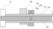
- FIG. 3 is an explanatory view showing an example of an intake camshaft.
- FIG. 4 is a block diagram showing in detail an example of the intake system of the engine.
- FIG. 5 is an explanatory diagram showing an example of the arrangement of intake valves and exhaust valves of the engine.
- FIG. 6 is a view showing a phase change of the intake valve.
- FIG. 7 is a flowchart showing an example of control performed in the engine control apparatus.
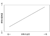
- FIG. 8 is an example of a map showing the relationship between the exhaust temperature and the retard amount of the intake valve.
- FIG. 1 is an overall configuration diagram of an engine in which an engine control device of an embodiment is incorporated.
- FIG. 2 is a schematic configuration diagram of the engine of the embodiment.
- FIG. 3 is an explanatory view showing an example of an intake camshaft.
- FIG. 9 is an example of a map showing the relationship between the boost pressure and the retard amount of the intake valve.
- FIG. 10 is an example of a map showing the relationship between the exhaust pressure and the throttle valve opening.
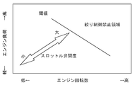
- FIG. 11 is an example of a map showing the relationship between the engine speed and engine load and the opening of the throttle valve.
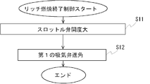
- FIG. 12 is an example of a flowchart for ending the rich combustion state.
- FIG. 13 is an explanatory diagram illustrating an example of an intake camshaft according to the second embodiment.
- FIG. 14 is an example of a map showing the relationship between the intake air amount and the advance amount.
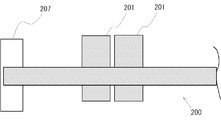
- FIG. 15 is an explanatory view showing an example of the exhaust camshaft.
- FIG. 16 is an example of a map showing the relationship between the exhaust temperature and the retard amount of the exhaust valve.
- FIG. 1 is an overall configuration diagram of an engine 50 in which the engine control device of the embodiment is incorporated.
- the engine 50 in this embodiment is a compression ignition type diesel engine, but can be a gasoline engine as long as it is an in-cylinder fuel injection type engine.
- the intake system 10 includes an air flow meter (A / C) 11, an intercooler (I / C) 12, and an intake manifold 13.
- the air flow meter 11 measures the amount of intake air.
- the intercooler 12 cools the intake air compressed by the supercharger 30.
- the intake manifold 13 distributes intake air to the cylinders 51a of the engine 50.
- the exhaust system 20 includes an exhaust manifold 21 and a catalyst 22.
- the exhaust manifold 21 merges exhaust from each cylinder 51a into one exhaust passage on the downstream side.
- the catalyst 22 purifies the exhaust.
- the supercharger 30 includes a compressor unit 31 and a turbine unit 32.
- the supercharger 30 is an exhaust-driven variable displacement turbocharger, and is provided with a compressor unit 31 interposed in the intake system 10 and a turbine unit 32 interposed in the exhaust system 20.
- the engine 50 includes a cylinder block 51, a cylinder head 52, a piston 53, a first intake valve 54A, a second intake valve B, an exhaust valve 55, a fuel injection valve 56, And an intake side VVT (Variable Valve Timing) 57.
- the intake side VVT 57 is an example of first phase changing means for retarding the phase of the first intake valve 54A from the phase of the second intake valve 54B, as will be described in detail later.
- the cylinder block 51 is formed with a cylinder 51a.
- a piston 53 is accommodated in the cylinder 51a.
- a cylinder head 52 is fixed to the upper surface of the cylinder block 51.
- the combustion chamber 58 is formed as a space surrounded by the cylinder block 51, the cylinder head 52, and the piston 53.
- the cylinder head 52 has an intake port 52a and an exhaust port 52b.
- the intake port 52 a guides intake air to the combustion chamber 58, and the exhaust port 52 b exhausts gas from the combustion chamber 58.
- the cylinder head 52 is provided with a first intake valve 54A, a second intake valve 54B, and an exhaust valve 55.
- the first intake valve 54A and the second intake valve 54B open and close the intake port 52a, and the exhaust valve 55 opens and closes the exhaust port 52b.
- FIG. 3 is an explanatory diagram of the intake camshaft 100 that drives the first intake valve 54A and the second intake valve 54B.
- the intake camshaft 100 has a double structure in which an internal shaft 101 is rotatably fitted in an external shaft 102.
- a first cam 103 is fixed to the inner shaft 101 by a fixing pin 104.
- the first cam 103 is exposed to the outside from a groove 102 a provided in the external shaft 102.
- the first cam 103 can change in phase as the inner shaft 101 rotates with respect to the outer shaft 102.
- a second cam 105 is fixed to the external shaft 102 by press-fitting.
- the first cam 103 drives the first intake valve 54A.
- the second cam 105 drives the second intake valve 54B.
- FIG. 4 is a block diagram showing the intake system 10 of the engine 50 in detail.
- an air flow meter 11, a supercharger 30, an intercooler 12, a throttle valve 60, an intake manifold 13, and an intake port 52a are arranged along the air flow.
- air is introduced into the cylinder 51a through the intake valve 54A (54B) driven by the intake side VVT 57.
- the throttle valve 60 adjusts the intake air amount.
- An EGR pipe 61 is connected between the throttle valve 60 and the intake manifold 13, that is, on the downstream side of the throttle valve 60.
- An EGR valve 62 is disposed in the EGR pipe 61.
- the throttle valve 60 is throttled by throttle control, the area indicated by A on the downstream side of the throttle valve 60 becomes negative pressure.
- the upstream side of the EGR pipe 61 from the EGR valve 62 becomes a high pressure due to exhaust.
- the EGR valve 62 opens and closes according to the pressure difference between the upstream side and the downstream side.
- the intake port 52a specifically includes partial intake ports In1 and In2 that branch and open from the upstream side toward the combustion chamber 58.
- the exhaust port 52b includes partial exhaust ports Ex1 and Ex2 branched and opened from the downstream side toward the combustion chamber 58.
- the first intake valve 54A opens and closes the partial intake port In1
- the second intake valve 54B opens and closes the partial intake port In2
- the two exhaust valves 55 open and close the partial exhaust ports Ex1 and Ex2.
- the partial intake port In1 has a smaller flow coefficient than the partial intake port In2. Specifically, the flow passage cross-sectional area of the partial intake port In1 is smaller than that of the partial intake port In2. For this reason, the valve diameter of the first intake valve 54A is smaller than that of the second intake valve 54B. As will be described in detail later, when the first intake valve 54A is retarded from the second intake valve 54B, the air from the second intake valve 54B is first introduced into the cylinder 51a. Thus, swirl can be generated by shifting the timing at which air is introduced into the cylinder 51a.
- the cylinder head 52 is provided with a fuel injection valve 56.
- the fuel injection valve 56 directly injects fuel into the cylinder.
- the cylinder head 52 is provided with an intake side VVT 57.
- a first intake valve 54A and a second intake valve 54B that can change the closing timing of the first intake valve 54A is applied. That is, the intake side VVT 57 changes the phase of the internal shaft 101 shown in FIG.
- the engine 50 is provided with various sensors. Specifically, for example, the air flow meter 11, the crank angle sensor 71 for detecting the crank angle and the engine speed NE, the water temperature sensor 72 for detecting the cooling water temperature of the engine 50, and the in-cylinder pressure P0 are detected. In-cylinder pressure sensor 73 is provided.
- the intake system 10 is provided with a supercharging pressure sensor 74 for detecting the supercharging pressure P and a temperature sensor 75 for detecting the intake air temperature P0 ′.
- the intake side VVT 57 is provided with a valve timing sensor 76 for detecting the valve timing.
- the ECU 1 is an electronic control device corresponding to a control unit, and includes a microcomputer and an input / output circuit including a CPU, a ROM, a RAM, and the like.
- Various sensors and switches such as the air flow meter 11 and the above-described sensors 71 to 76 are electrically connected to the ECU 1.
- Various control objects such as the supercharger 30, the fuel injection valve 56, and the intake side VVT 57 are electrically connected.
- ROM is a configuration for storing programs, map data, and the like in which various processes executed by the CPU are described.
- the CPU executes a process based on a program stored in the ROM while using a temporary storage area of the RAM as necessary, various control means, determination means, detection means, and the like are functionally realized in the ECU 1. .
- the ECU 1 retards the phase of the first intake valve 54A from the phase of the second intake valve 54B by the intake side VVT 57 so that the amount of air in the cylinder of the engine 50 is reduced to the target value and rich combustion is performed.
- the phase control of the intake valve is performed. Further, when the intake valve phase control by the intake side VVT 87 is performed and the amount of air in the cylinder 51a cannot be reduced below the target value, the following measures are taken. That is, following the intake valve phase control, the throttle valve 60 performs throttle control of the throttle valve so that the air amount in the cylinder 51a is equal to or less than the target value.
- the ECU 1 performs phase control of the intake valve of the first intake valve 54A and the second intake valve 54B that retards the closing timing of the first intake valve 54A. Specifically, as shown in FIG. 6, the valve timing of the second intake valve 54B is fixed and the valve opening timing and the valve closing timing of the first intake valve 54A are changed in an integrated manner. The valve closing timing of the intake valve 54A is retarded. Thus, the closing timing of the first intake valve 54A is retarded relative to the closing timing of the second intake valve 54B. The ECU 1 retards the closing timing of the first intake valve 54A with the intake side VVT 57 as a control target.
- the retard angle control performed by the ECU 1 is a retard angle control in the sense that the first intake valve 54A is closed late. Accordingly, the closing timing of the first intake valve 54A is set to be retarded from the intake bottom dead center.
- the ECU 1 determines the intake air amount, the exhaust pressure, the engine speed, the load, the exhaust temperature, the supercharging based on the information acquired by the various sensors 71 to 76 and the information acquired by the various sensors 71 to 76. Know pressure etc. Further, the target value of the air amount in the cylinder for rich combustion is grasped.
- FIG. 7 is a flowchart showing an example of control (rich combustion control) performed in the engine control apparatus. This control is performed mainly by the ECU 1.
- step S1 the phase control of the intake valve is performed. Specifically, the ECU 1 issues a command to the intake side VVT 57 to perform the retard angle control of the first intake valve 54A.
- the retard control of the first intake valve 54A air is introduced from the second intake valve 54B prior to the first intake valve 54A, and swirl can be generated. The generation of swirl can improve combustion and suppress the generation of smoke. Further, since the first intake valve 54A disposed at a position close to the cylinder 51a is controlled, good responsiveness is ensured. If the throttle valve 60 is first controlled, the amount of air is adjusted without considering the movement of the piston 53 and the timing of combustion. On the other hand, by performing the phase control of the intake valve first, the cyclic air amount can be adjusted.
- step S2 it is determined whether the intake air amount is smaller than the target air amount in the cylinder 51a by the phase control of the intake valve in step S1. If it is determined as Yes in step S2, the process proceeds to step S4. In step S4, measures such as changing the fuel injection specifications are taken, and rich combustion is performed.
- step S3 throttle control of the throttle valve 60 is performed. That is, the air amount is controlled by the throttle valve 60 only when the air amount cannot be reduced below the target value even if the phase control of the intake valve is performed.
- the throttle control of the throttle valve 60 is adjusted by the amount that is insufficient by the phase control of the intake valve. For this reason, it is possible to minimize deterioration in responsiveness due to a delay in gas transportation from the throttle valve 60 into the cylinder 51a.
- step S4 the process of step S4 is performed. That is, rich combustion is performed.
- the following effects are achieved by performing the phase control of the intake valve prior to the throttle control of the throttle valve.
- diffusion of fuel spray by swirl is promoted.
- fuel adhesion to the cylinder bore wall and oil dilution by the fuel can be reduced.
- the amount of air in the cylinder 51a decreases. That is, since the density of the gas in the cylinder 51a decreases, the penetration force of the fuel spray increases. As a result, fuel adheres to the cylinder bore wall and oil dilution tends to occur.
- the phase control of the intake valve is performed prior to the throttle control of the throttle valve, thereby promoting the diffusion of spray due to the occurrence of swirl. As a result, combustion adherence to the in-cylinder bore wall and oil dilution are suppressed.
- the exhaust temperature is reduced due to the combustion temperature drop due to the reduction of the effective compression ratio. For this reason, the rich combustion continuation time can be extended. Thereby, the catalyst control time can be shortened and the fuel consumption can be improved. That is, exhaust gas temperature rises when rich combustion is performed. For this reason, in particular, when a supercharger is mounted, the temperature may be restricted for protection of the supercharger. Even in such a case, rich combustion can be continued.
- the pressure of the intake pipe on the downstream side (particularly, the region indicated by A in FIG. 4) from the throttle valve can be maintained high.
- the controllability of EGR is improved. That is, the EGR valve 62 operates according to the pressure difference between the upstream side and the downstream side. For this reason, if the pressure in the region indicated by A in FIG. 4 is reduced by the throttle of the throttle valve 60 and the pressure difference between the upstream and downstream of the EGR valve 62 increases, the controllability deteriorates. That is, a large amount of EGR gas is introduced only by slightly opening the EGR valve 62, and the controllability of EGR deteriorates.
- throttle control of the throttle valve is accompanied by an increase in pump loss, which may cause a decrease in torque and a deterioration in drivability.
- the intake valve phase control the intake port 52a is opened and the first intake valve 54A is closed slowly to reduce the amount of air in the cylinder, so that deterioration of pump loss is suppressed. As a result, the deterioration of drivability is also suppressed.
- step S1 various items that can be considered in step S1 will be described. In addition, for convenience of explanation, these items will be described individually, but control can be performed in consideration of a plurality of items at the same time. ⁇ Exhaust temperature ⁇
- step S1 the ECU 1 can take into account the exhaust temperature of the engine 50.
- FIG. 8 is an example of a map showing the relationship between the exhaust temperature and the retard amount of the intake valve. If the exhaust temperature becomes too high due to the rich combustion, it is not desirable to continue the rich combustion. In particular, in the case where the supercharger 30 is provided, there may be restrictions from the viewpoint of supercharger 30 protection. For this reason, the higher the exhaust gas temperature, the larger the retardation amount of the phase of the first intake valve 54A. Thereby, an effective compression ratio can be reduced and the temperature of exhaust gas can be reduced. Thereby, protection of the supercharger 30 can be aimed at.
- the rich combustion continuation time can be extended while protecting the supercharger 30 by setting the temperature of the exhaust gas within a range in which the supercharger 30 can be protected.
- catalyst control time can be shortened and it can contribute to fuel consumption improvement.
- FIG. 9 is an example of a map showing the relationship between the boost pressure and the retard amount of the intake valve.
- the change in supercharging pressure is accompanied by a response delay due to a so-called turbo lag. For this reason, even if the supercharging pressure is controlled, the actual supercharging pressure may exceed the target supercharging pressure.
- the actual supercharging pressure exceeds the target supercharging pressure as described above, there is a concern that controllability and response may be deteriorated when trying to cope with the throttle valve throttle. Therefore, by increasing the retard amount of the first intake valve 54A, the amount of air increased with the increase in supercharging pressure is reduced. Thereby, controllability and responsiveness can be maintained. Such control is advantageous in terms of pump loss.
- step S3 various items that can be considered in throttle control (step S3) of the throttle valve will be described.
- these items will be described individually, but control can be performed in consideration of a plurality of items at the same time.
- FIG. 10 is an example of a map showing the relationship between the exhaust pressure and the throttle valve opening.
- the ECU 1 increases the opening of the throttle valve 60 as the exhaust pressure of the engine 50 increases. In other words, the throttle amount of the throttle valve 60 is reduced. Further, the ECU 1 suppresses throttle control of the throttle valve when the exhaust pressure of the engine 50 becomes equal to or higher than a predetermined value.
- FIG. 11 is an example of a map showing the relationship between the engine speed and engine load and the opening of the throttle valve 60.
- the ECU 1 increases the opening degree of the throttle valve 60 as the engine 50 is rotated at a higher speed and a higher load.
- the ECU 1 Aperture control is suppressed, that is, prohibited.
- step S11 the opening degree of the throttle valve 60 throttled in step S11 is increased.
- step S12 the first intake valve is controlled to the advance side.
- the engine control apparatus of the embodiment it is possible to suppress the generation of smoke and improve the response of rich combustion.
- Example 2 will be described with reference to FIGS.
- the second embodiment is different from the first embodiment in that the second embodiment includes an intake side VVT 157 corresponding to a second phase changing unit that changes the phase of the second intake valve 54B.
- the intake side VVT 157 is attached to the external shaft 102 as shown in FIG.
- the intake side VVT 157 changes the phase of the second intake valve 54B driven by the second cam 105 press-fitted into the external shaft 102.
- the ECU 1 performs advance angle control for advancing the second intake valve 54B by the intake side VVT 157 as well as delay angle control for the first intake valve 54A by the intake side VVT 57.
- the swirl can be strengthened, and as a result, the occurrence of smoke can be further suppressed.
- FIG. 14 is an example of a map showing the relationship between the intake air amount and the advance amount of the second intake valve 54B.
- the ECU 1 increases the opening of the throttle valve 60 and then advances the second angle when the rich combustion state is terminated.
- the intake valve 64B is retarded to return to the original state. Specifically, in step S11 shown in FIG. 12, the rich combustion state is terminated by delaying the second intake valve 54B together with the advance angle of the first intake valve 54A.
- Example 3 will be described with reference to FIGS. 15 and 16.
- the third embodiment differs from the first embodiment in that an exhaust side VVT 207 corresponding to a third phase changing means for changing the phase of the exhaust valve 55 is provided.
- the exhaust side VVT 207 is attached to an exhaust camshaft 200 into which an exhaust cam 201 that drives the exhaust valve 55 is press-fitted. Since the configuration of the exhaust side VVT 207 is the same as that of the intake side VVT 57, a detailed description thereof is omitted.
- FIG. 16 is an example of a map showing the relationship between the exhaust temperature and the retard amount of the exhaust valve 55.
- the ECU 1 increases the retard amount of the exhaust valve 55 by the exhaust side VVT 207 as the temperature of the exhaust becomes higher.
Abstract
Description
≪排気の温度≫ Here, various items that can be considered in step S1 will be described. In addition, for convenience of explanation, these items will be described individually, but control can be performed in consideration of a plurality of items at the same time.
≪Exhaust temperature≫
≪過給圧≫ In step S1, the ECU 1 can take into account the exhaust temperature of the
≪Supercharging pressure≫
≪排気圧≫ Next, various items that can be considered in throttle control (step S3) of the throttle valve will be described. In addition, for convenience of explanation, these items will be described individually, but control can be performed in consideration of a plurality of items at the same time.
≪Exhaust pressure≫
≪エンジン回転数及びエンジン負荷≫ When the
≪Engine speed and engine load≫
30…過給機
50…エンジン
54A…第1の吸気弁
54B…第2の吸気弁
55…排気弁
57、157…吸気側VVT
60…スロットル弁
61…EGRパイプ
62…EGR弁
100…吸気カムシャフト
200…排気カムシャフト
207…排気側VVT 1 ... ECU
30 ...
60 ...
Claims (13)
- 筒内燃料噴射式のエンジンにおいて、
第1の吸気弁の位相を第2の吸気弁の位相よりも遅角する第1位相変更手段と、
前記エンジンの吸入空気量を調整するスロットル弁を備え、
前記エンジンの気筒内の空気量を目標値まで減少させてリッチ燃焼となるように、前記第1位相変更手段によって前記第1の吸気弁の位相を前記第2の吸気弁の位相よりも遅角させる吸気弁の位相制御を行うとともに、前記第1位相変更手段による吸気弁の位相制御を行って前記気筒内の空気量が前記目標値以下に減少することができない場合に、前記吸気弁の位相制御に引き続いて前記スロットル弁により前記気筒内の空気量が前記目標値以下となるように前記スロットル弁の絞り制御を行う制御部と、
を、備えたエンジンの制御装置。 In the cylinder fuel injection type engine,
First phase changing means for retarding the phase of the first intake valve relative to the phase of the second intake valve;
A throttle valve for adjusting the intake air amount of the engine;
The phase of the first intake valve is retarded from the phase of the second intake valve by the first phase changing means so that the amount of air in the cylinder of the engine is reduced to a target value and rich combustion is performed. The phase of the intake valve is controlled when the phase control of the intake valve to be performed and the phase control of the intake valve by the first phase changing unit cannot be performed to reduce the air amount in the cylinder below the target value. A control unit that performs throttle control of the throttle valve so that the amount of air in the cylinder is equal to or less than the target value by the throttle valve following control;
An engine control device. - 前記第2の吸気弁の位相を変更する第2位相変更手段を備え、
前記制御部は、前記第1位相変更手段による前記第1の吸気弁に対する遅角制御とともに、前記第2位相変更手段による前記第2の吸気弁を進角させる進角制御を行う請求項1記載のエンジンの制御装置。 Second phase changing means for changing the phase of the second intake valve;
2. The control unit performs an advance angle control for advancing the second intake valve by the second phase change unit, together with a retard angle control for the first intake valve by the first phase change unit. Engine control device. - 前記制御部は、吸入空気量が少ないほど、前記第2の吸気弁の進角量を大きくする請求項2記載のエンジンの制御装置。 3. The engine control apparatus according to claim 2, wherein the control unit increases the advance amount of the second intake valve as the intake air amount decreases.
- 前記制御部は、前記エンジンの排気圧が予め定めた所定値以上となったときに、前記スロットル弁の絞り制御を抑制する請求項1乃至3のいずれか一項記載のエンジンの制御装置。 4. The engine control device according to claim 1, wherein the control unit suppresses throttle control of the throttle valve when an exhaust pressure of the engine becomes a predetermined value or more.
- 前記制御部は、前記エンジンの排気圧が大きいほど、前記スロットル弁の開度を大きくする請求項1乃至4のいずれか一項記載のエンジンの制御装置。 The engine control device according to any one of claims 1 to 4, wherein the control unit increases the opening of the throttle valve as the exhaust pressure of the engine increases.
- 前記制御部は、前記エンジンが高回転かつ高負荷である時に前記スロットル弁の絞り制御を抑制する請求項1乃至5のいずれか一項記載のエンジンの制御装置。 The engine control device according to any one of claims 1 to 5, wherein the control unit suppresses throttle control of the throttle valve when the engine is at a high rotation speed and a high load.
- 前記制御部は、前記エンジンが高回転かつ高負荷となるほど、前記スロットル弁の開度を大きくする請求項1乃至6のいずれか一項記載のエンジンの制御装置。 The engine control device according to any one of claims 1 to 6, wherein the control unit increases the opening degree of the throttle valve as the engine is rotated at a higher speed and a higher load.
- 前記制御部は、排気の温度が高いほど、前記第1の吸気弁の位相の遅角量を大きくする請求項1乃至7記載のエンジンの制御装置。 The engine control device according to any one of claims 1 to 7, wherein the control unit increases the retardation amount of the phase of the first intake valve as the temperature of the exhaust gas increases.
- さらに、過給機を有し、
前記制御部は、前記過給機の過給圧が目標過給圧よりも大きい場合に、前記第1の吸気弁の位相の遅角量を大きくする請求項1乃至8記載のエンジンの制御装置。 In addition, it has a supercharger,
9. The engine control device according to claim 1, wherein the control unit increases a retardation amount of the phase of the first intake valve when a supercharging pressure of the supercharger is larger than a target supercharging pressure. 10. . - さらに、排気弁の位相を変更する第3位相変更手段を備え、
前記制御部は、排気の温度が高いほど、前記第3位相変更手段による前記排気弁の遅角量を大きくする請求項8又は請求項9記載のエンジンの制御装置。 Furthermore, a third phase changing means for changing the phase of the exhaust valve is provided,
10. The engine control device according to claim 8, wherein the control unit increases the retard amount of the exhaust valve by the third phase changing unit as the temperature of the exhaust gas is higher. - 前記制御部は、リッチ燃焼状態を終了させるときに、前記スロットル弁の開度を大きくした後、前記遅角していた第1の吸気弁を進角させる請求項1乃至請求項10のいずれか一項記載のエンジンの制御装置。 11. The control unit according to claim 1, wherein when the rich combustion state is terminated, the control unit advances the first intake valve that has been retarded after increasing the opening of the throttle valve. The engine control device according to one item.
- 前記制御部は、リッチ燃焼状態を終了させるときに、前記スロットル弁の開度を大きくした後、前記進角していた第2の吸気弁を遅角させる請求項2乃至請求項10のいずれか一項記載のエンジンの制御装置。 11. The control unit according to claim 2, wherein when the rich combustion state is terminated, the control unit retards the advanced second intake valve after increasing the opening of the throttle valve. The engine control device according to one item.
- 筒内燃料噴射式のエンジンにおいて、
第1の吸気弁の位相を第2の吸気弁の位相よりも遅角する第1位相変更手段と、
前記エンジンの気筒内の空気量を目標値まで減少させてリッチ燃焼となるように、前記第1位相変更手段によって前記第1の吸気弁の位相を前記第2の吸気弁の位相よりも遅角させる吸気弁の位相制御を行う制御部と、
を備えたエンジンの制御装置。 In the cylinder fuel injection type engine,
First phase changing means for retarding the phase of the first intake valve relative to the phase of the second intake valve;
The phase of the first intake valve is retarded from the phase of the second intake valve by the first phase changing means so that the amount of air in the cylinder of the engine is reduced to a target value and rich combustion is performed. A control unit for controlling the phase of the intake valve to be
An engine control device comprising:
Priority Applications (5)
| Application Number | Priority Date | Filing Date | Title |
|---|---|---|---|
| US13/574,154 US8887675B2 (en) | 2010-11-08 | 2010-11-08 | Control device for changing phase of multiple independent intake valves in engine |
| JP2012542738A JP5418692B2 (en) | 2010-11-08 | 2010-11-08 | Engine control device |
| EP10859563.8A EP2639431B1 (en) | 2010-11-08 | 2010-11-08 | Control device for engine |
| PCT/JP2010/069860 WO2012063314A1 (en) | 2010-11-08 | 2010-11-08 | Control device for engine |
| CN201080065035.3A CN102782288B (en) | 2010-11-08 | 2010-11-08 | The control device of electromotor |
Applications Claiming Priority (1)
| Application Number | Priority Date | Filing Date | Title |
|---|---|---|---|
| PCT/JP2010/069860 WO2012063314A1 (en) | 2010-11-08 | 2010-11-08 | Control device for engine |
Publications (1)
| Publication Number | Publication Date |
|---|---|
| WO2012063314A1 true WO2012063314A1 (en) | 2012-05-18 |
Family
ID=46050496
Family Applications (1)
| Application Number | Title | Priority Date | Filing Date |
|---|---|---|---|
| PCT/JP2010/069860 WO2012063314A1 (en) | 2010-11-08 | 2010-11-08 | Control device for engine |
Country Status (5)
| Country | Link |
|---|---|
| US (1) | US8887675B2 (en) |
| EP (1) | EP2639431B1 (en) |
| JP (1) | JP5418692B2 (en) |
| CN (1) | CN102782288B (en) |
| WO (1) | WO2012063314A1 (en) |
Cited By (1)
| Publication number | Priority date | Publication date | Assignee | Title |
|---|---|---|---|---|
| CN104932437A (en) * | 2014-03-18 | 2015-09-23 | 深圳市航天无线通信技术有限公司 | Diesel-powered car fuel consumption statistics device based on OBD data, and method thereof |
Families Citing this family (4)
| Publication number | Priority date | Publication date | Assignee | Title |
|---|---|---|---|---|
| JP6252450B2 (en) | 2014-11-28 | 2017-12-27 | トヨタ自動車株式会社 | Control device for internal combustion engine |
| DE102015223145A1 (en) * | 2015-11-24 | 2017-05-24 | Robert Bosch Gmbh | Method for operating an internal combustion engine |
| DE102017113363B4 (en) * | 2017-06-19 | 2022-06-23 | Schaeffler Technologies AG & Co. KG | Variable valve train of an internal combustion engine |
| FR3116563A1 (en) * | 2020-11-25 | 2022-05-27 | Vitesco Technologies | Method and system for regulating the combustion of an internal combustion engine |
Citations (6)
| Publication number | Priority date | Publication date | Assignee | Title |
|---|---|---|---|---|
| JPH07224626A (en) * | 1994-02-14 | 1995-08-22 | Mazda Motor Corp | Control device for engine |
| JPH09170462A (en) * | 1995-12-19 | 1997-06-30 | Isuzu Motors Ltd | Output controller for internal combustion engine |
| JPH11141375A (en) * | 1997-11-10 | 1999-05-25 | Nissan Motor Co Ltd | Boost control device for internal combustion engine with supercharger |
| JP2004176544A (en) * | 2002-11-22 | 2004-06-24 | Toyota Motor Corp | Power output device, its control method, and vehicle |
| JP2005188356A (en) * | 2003-12-25 | 2005-07-14 | Honda Motor Co Ltd | Exhaust emission control device for internal combustion engine |
| JP2010014122A (en) * | 2009-09-08 | 2010-01-21 | Mitsubishi Heavy Ind Ltd | Engine with exhaust turbocharger having waist gate valve and its operation method |
Family Cites Families (14)
| Publication number | Priority date | Publication date | Assignee | Title |
|---|---|---|---|---|
| US5230320A (en) | 1991-06-27 | 1993-07-27 | Mazda Motor Corporation | Intake and exhaust control system for automobile engine |
| JP3565912B2 (en) * | 1994-09-28 | 2004-09-15 | 本田技研工業株式会社 | Switching control method of valve operating characteristics and air-fuel ratio in internal combustion engine |
| US6519933B2 (en) * | 2000-03-21 | 2003-02-18 | Toyota Jidosha Kabushiki Kaisha | Internal combustion engine having variable valve control system and NOx catalyst |
| US6397800B2 (en) * | 2000-03-23 | 2002-06-04 | Nissan Motor Co., Ltd. | Valve control device of internal combustion engine |
| US6386156B1 (en) * | 2000-08-29 | 2002-05-14 | Ford Global Technologies, Inc. | Transitions among operating modes in an engine with a hybrid valvetrain |
| CN101389830A (en) * | 2006-02-22 | 2009-03-18 | 丰田自动车株式会社 | Variable valve timing apparatus and control method therefor |
| JP4804384B2 (en) * | 2007-03-08 | 2011-11-02 | 日立オートモティブシステムズ株式会社 | Variable valve operating device and control device for internal combustion engine |
| US8061318B2 (en) * | 2007-09-27 | 2011-11-22 | GM Global Technology Operations LLC | Method and apparatus for continuously variable differential phasing of engine valve operation |
| JP4747158B2 (en) | 2007-12-11 | 2011-08-17 | 本田技研工業株式会社 | Valve operating apparatus provided with phase control means |
| US7810460B2 (en) * | 2008-02-15 | 2010-10-12 | Gm Global Technology Operations, Inc. | Adaptive individual dynamic volumetric efficiency optimization for engines with variable cam phasers and variable lift |
| JP5381067B2 (en) * | 2008-02-29 | 2014-01-08 | 日産自動車株式会社 | Valve control device for internal combustion engine |
| JP2009228640A (en) | 2008-03-25 | 2009-10-08 | Honda Motor Co Ltd | Valve train for engine |
| JP2010024865A (en) | 2008-07-15 | 2010-02-04 | Toyota Motor Corp | Control device for engine |
| JP5024571B2 (en) * | 2009-11-06 | 2012-09-12 | 三菱自動車工業株式会社 | Variable valve operating device for internal combustion engine |
-
2010
- 2010-11-08 JP JP2012542738A patent/JP5418692B2/en not_active Expired - Fee Related
- 2010-11-08 WO PCT/JP2010/069860 patent/WO2012063314A1/en active Application Filing
- 2010-11-08 CN CN201080065035.3A patent/CN102782288B/en not_active Expired - Fee Related
- 2010-11-08 US US13/574,154 patent/US8887675B2/en not_active Expired - Fee Related
- 2010-11-08 EP EP10859563.8A patent/EP2639431B1/en not_active Not-in-force
Patent Citations (6)
| Publication number | Priority date | Publication date | Assignee | Title |
|---|---|---|---|---|
| JPH07224626A (en) * | 1994-02-14 | 1995-08-22 | Mazda Motor Corp | Control device for engine |
| JPH09170462A (en) * | 1995-12-19 | 1997-06-30 | Isuzu Motors Ltd | Output controller for internal combustion engine |
| JPH11141375A (en) * | 1997-11-10 | 1999-05-25 | Nissan Motor Co Ltd | Boost control device for internal combustion engine with supercharger |
| JP2004176544A (en) * | 2002-11-22 | 2004-06-24 | Toyota Motor Corp | Power output device, its control method, and vehicle |
| JP2005188356A (en) * | 2003-12-25 | 2005-07-14 | Honda Motor Co Ltd | Exhaust emission control device for internal combustion engine |
| JP2010014122A (en) * | 2009-09-08 | 2010-01-21 | Mitsubishi Heavy Ind Ltd | Engine with exhaust turbocharger having waist gate valve and its operation method |
Cited By (1)
| Publication number | Priority date | Publication date | Assignee | Title |
|---|---|---|---|---|
| CN104932437A (en) * | 2014-03-18 | 2015-09-23 | 深圳市航天无线通信技术有限公司 | Diesel-powered car fuel consumption statistics device based on OBD data, and method thereof |
Also Published As
| Publication number | Publication date |
|---|---|
| EP2639431A4 (en) | 2014-05-28 |
| US20120290197A1 (en) | 2012-11-15 |
| US8887675B2 (en) | 2014-11-18 |
| CN102782288A (en) | 2012-11-14 |
| EP2639431A1 (en) | 2013-09-18 |
| JP5418692B2 (en) | 2014-02-19 |
| CN102782288B (en) | 2016-06-08 |
| EP2639431B1 (en) | 2017-08-09 |
| JPWO2012063314A1 (en) | 2014-05-12 |
Similar Documents
| Publication | Publication Date | Title |
|---|---|---|
| US7415966B2 (en) | Engine | |
| JP4277897B2 (en) | Control device for internal combustion engine | |
| EP2096284B1 (en) | Method, system and computer program product for controlling an internal combustion engine | |
| US20060169246A1 (en) | Method of controlling premix compression self-igniting internal combustion engine | |
| JP5092962B2 (en) | Control device for an internal combustion engine with a supercharger | |
| JP5418692B2 (en) | Engine control device | |
| JP4666162B2 (en) | Fuel injection control device for internal combustion engine | |
| WO2013073345A1 (en) | Internal combustion engine control device | |
| JP2012097639A (en) | Control device for internal combustion engine | |
| US10408144B2 (en) | Engine control device | |
| JP4797868B2 (en) | Turbocharged engine | |
| JP2006348865A (en) | Fuel injection control device of internal combustion engine | |
| JP2005083285A (en) | Valve system of engine with supercharger | |
| JP2007182828A (en) | Control device for internal combustion engine | |
| JP4930726B2 (en) | Fuel injection device for internal combustion engine | |
| JP6380915B2 (en) | Engine control device | |
| JP4200356B2 (en) | Fuel control apparatus for in-cylinder internal combustion engine | |
| JP6312048B2 (en) | Engine control device | |
| JP2012122387A (en) | Internal combustion engine | |
| WO2017150077A1 (en) | Engine control device | |
| EP2584179B1 (en) | Control device for internal combustion engine | |
| JP5817634B2 (en) | Control device for internal combustion engine | |
| JP5067205B2 (en) | Control device for internal combustion engine | |
| JP2013147956A (en) | Valve gear of engine | |
| JP2010261358A (en) | Control apparatus for internal combustion engine |
Legal Events
| Date | Code | Title | Description |
|---|---|---|---|
| WWE | Wipo information: entry into national phase |
Ref document number: 201080065035.3 Country of ref document: CN |
|
| WWE | Wipo information: entry into national phase |
Ref document number: 2012542738 Country of ref document: JP |
|
| 121 | Ep: the epo has been informed by wipo that ep was designated in this application |
Ref document number: 10859563 Country of ref document: EP Kind code of ref document: A1 |
|
| WWE | Wipo information: entry into national phase |
Ref document number: 13574154 Country of ref document: US |
|
| REEP | Request for entry into the european phase |
Ref document number: 2010859563 Country of ref document: EP |
|
| WWE | Wipo information: entry into national phase |
Ref document number: 2010859563 Country of ref document: EP |
|
| NENP | Non-entry into the national phase |
Ref country code: DE |