WO2012060171A1 - 動画像符号化装置、動画像復号装置、動画像伝送システム、動画像符号化装置の制御方法、動画像復号装置の制御方法、動画像符号化装置制御プログラム、動画像復号装置制御プログラム、および記録媒体 - Google Patents
動画像符号化装置、動画像復号装置、動画像伝送システム、動画像符号化装置の制御方法、動画像復号装置の制御方法、動画像符号化装置制御プログラム、動画像復号装置制御プログラム、および記録媒体 Download PDFInfo
- Publication number
- WO2012060171A1 WO2012060171A1 PCT/JP2011/072288 JP2011072288W WO2012060171A1 WO 2012060171 A1 WO2012060171 A1 WO 2012060171A1 JP 2011072288 W JP2011072288 W JP 2011072288W WO 2012060171 A1 WO2012060171 A1 WO 2012060171A1
- Authority
- WO
- WIPO (PCT)
- Prior art keywords
- image
- encoding
- decoding
- updated
- encoded
- Prior art date
- Legal status (The legal status is an assumption and is not a legal conclusion. Google has not performed a legal analysis and makes no representation as to the accuracy of the status listed.)
- Ceased
Links
Images

















Classifications
-
- H—ELECTRICITY
- H04—ELECTRIC COMMUNICATION TECHNIQUE
- H04N—PICTORIAL COMMUNICATION, e.g. TELEVISION
- H04N19/00—Methods or arrangements for coding, decoding, compressing or decompressing digital video signals
- H04N19/10—Methods or arrangements for coding, decoding, compressing or decompressing digital video signals using adaptive coding
- H04N19/169—Methods or arrangements for coding, decoding, compressing or decompressing digital video signals using adaptive coding characterised by the coding unit, i.e. the structural portion or semantic portion of the video signal being the object or the subject of the adaptive coding
- H04N19/17—Methods or arrangements for coding, decoding, compressing or decompressing digital video signals using adaptive coding characterised by the coding unit, i.e. the structural portion or semantic portion of the video signal being the object or the subject of the adaptive coding the unit being an image region, e.g. an object
-
- H—ELECTRICITY
- H04—ELECTRIC COMMUNICATION TECHNIQUE
- H04N—PICTORIAL COMMUNICATION, e.g. TELEVISION
- H04N19/00—Methods or arrangements for coding, decoding, compressing or decompressing digital video signals
- H04N19/50—Methods or arrangements for coding, decoding, compressing or decompressing digital video signals using predictive coding
- H04N19/597—Methods or arrangements for coding, decoding, compressing or decompressing digital video signals using predictive coding specially adapted for multi-view video sequence encoding
-
- H—ELECTRICITY
- H03—ELECTRONIC CIRCUITRY
- H03M—CODING; DECODING; CODE CONVERSION IN GENERAL
- H03M7/00—Conversion of a code where information is represented by a given sequence or number of digits to a code where the same, similar or subset of information is represented by a different sequence or number of digits
- H03M7/30—Compression; Expansion; Suppression of unnecessary data, e.g. redundancy reduction
- H03M7/3084—Compression; Expansion; Suppression of unnecessary data, e.g. redundancy reduction using adaptive string matching, e.g. the Lempel-Ziv method
- H03M7/3088—Compression; Expansion; Suppression of unnecessary data, e.g. redundancy reduction using adaptive string matching, e.g. the Lempel-Ziv method employing the use of a dictionary, e.g. LZ78
Definitions
- the present invention relates to a moving image encoding apparatus that encodes a distance video, a control method of the moving image encoding apparatus, a moving image encoding apparatus control program, and a moving image decoding that decodes encoded data encoded by these
- the present invention relates to an apparatus, a video decoding device control method, a video decoding device control program, a video transmission system including the same, and a recording medium.
- the subject can be recognized in three dimensions by viewing the image for the left eye with the left eye and the image for the right eye with the right eye, so two images corresponding to the left and right eyes are necessary. Become.
- the distance image is an image expressing the distance from the camera to the subject for each pixel for all the subjects in the image.
- the distance from the camera to the subject can be obtained by a distance measuring device installed in the vicinity of the camera, or by analyzing texture images taken by the camera from two or more viewpoints. can do.
- MPEG Moving Depth Experts Group
- ISO / IEC International Electrotechnical Commission
- the distance image is an image expressed in 8-bit gray scale.
- a higher brightness is assigned as the distance is shorter, so that the subject closer to the camera becomes whiter and the subject farther away becomes blacker.
- the distance for each pixel of the subject reflected in the texture image can be known, so that the subject can be restored to a three-dimensional shape in 256 stages.
- the texture image can be converted into the texture image from the other viewpoint.
- the occurrence of occlusion is prevented by using a plurality of viewpoint images.
- the texture from the viewpoint A is projected and converted to the texture image from the virtual viewpoint B
- the texture from the virtual viewpoint B is similarly applied from the texture image from the viewpoint C, which is a viewpoint different from A. Project to an image.
- two images from the same virtual viewpoint B can be created, and the blind image is different between the texture image from the viewpoint A and the texture image from the viewpoint C. Therefore, the occlusion in the image from one viewpoint is reduced from the other viewpoint. It can be supplemented by images.
- occlusion can be supplemented for the projection conversion to the virtual viewpoint on the line connecting the viewpoint A and the viewpoint C, and an image from the virtual viewpoint on the line can be created.
- Non-Patent Document 1 discloses a method of compressing a video from a plurality of viewpoints by efficiently eliminating the redundancy of a video between a plurality of viewpoints (video having an image as each frame). By applying this to two groups of multiple texture images and multiple distance images, it becomes possible to eliminate redundancy between texture images and between distance images. Transmission data can be compressed.
- a distance video at a specific viewpoint is created by performing the above-described projection conversion on a distance video at a certain viewpoint, thereby creating a distance video at a specific viewpoint and removing holes in the created distance video.
- a method for generating a video is disclosed.
- JP 2009-105894 A Japanese Patent Publication “JP 2009-105894 A (published May 14, 2009)”
- the distance image represents the distance from the camera to the subject as discrete values step by step for each pixel, and has the following characteristics.
- the first feature is that the edge portion of the subject is in common with the texture image. That is, as long as the texture image includes information that can distinguish the subject and the background as an image, the boundary (edge) between the subject and the background is common to the texture image and the distance image. Therefore, the edge information of the subject is one of the large elements of the correlation information between the texture image and the distance image.
- the second feature is that the distance depth value is relatively flat in the portion inside the edge of the subject.
- the texture image shows information about the clothes worn by the person, but the distance image does not show the clothes pattern information, but only the depth information. Is done. For this reason, the distance depth value on the same subject is flat or changes more slowly than the texture image.
- the pixels are divided for each range where the distance / depth value is constant, the distance / depth value is constant within that range, so very efficient coding is performed without performing orthogonal transformation or the like. Can be performed. Furthermore, if the range to be divided is determined based on some rule in the texture image, it is not necessary to transmit information regarding the divided range, and the coding efficiency can be further improved.
- the pixel group included in the range divided based on the distance depth value is called a segment. Since the coding efficiency can be improved as the number of segments is smaller, the shape of the segment is not limited, and the coding efficiency can be further improved by using a flexible shape.
- Non-Patent Document 1 the compression of the texture image is promoted by reusing square segments between temporally adjacent frames or between different viewpoint images.
- an image is divided into square segments (blocks) by a technique called motion compensation vector or parallax compensation vector, and blocks between temporally adjacent frames or different viewpoint images are blocked.
- the data is compressed by reusing.
- Non-Patent Document 1 when the method described in Non-Patent Document 1 is applied to the distance image divided into the flexible segment shapes described above, the encoding efficiency is extremely deteriorated. This is because the method described in Patent Document 1 is a method suitable for a method in which segments are square and each segment is orthogonally transformed. When the segments are made flexible, the vector information to be transmitted becomes enormous. It is because it ends.
- Patent Document 1 substitutes a single viewpoint for a distance image of a plurality of viewpoints, an error becomes large and the quality is greatly deteriorated.
- the present invention has been made in view of the above problems, and an object of the present invention is to realize a moving picture coding apparatus and the like that can perform coding efficiently.
- a moving image encoding device is a moving image encoding device that encodes a moving image, in which each frame image of the moving image is divided into a plurality of regions.
- a representative value determining means for determining a representative value of each area divided by the image dividing means, and a number sequence in which the representative values determined by the representative value determining means are arranged in a predetermined order for each frame image.
- Adaptive coding means for adaptively updating and coding a codebook in which a sequence pattern and a code word are associated, and generating coded data of the frame image, and comprising:
- the adaptive encoding means uses, as the updated codebook, a codebook that has been updated when a frame image other than the frame image to be adaptively encoded is adaptively encoded. .
- a control method for a moving image encoding device is a control method for a moving image encoding device that encodes a moving image, in which each frame image of the moving image is divided into a plurality of regions.
- Adaptive encoding for adaptively updating and encoding a codebook in which a sequence pattern and a code word are associated, and generating encoded data of the frame image,
- the code book to be updated the code book that has been updated when the frame image other than the frame image to be adaptively encoded is adaptively encoded. It is characterized by using.
- each frame image of a moving image is divided into a plurality of regions, and a representative value of each divided region is determined. Then, for each frame image, adaptive encoding is performed on a numerical sequence in which representative values are arranged in a predetermined order.
- the predetermined order is an order in which the position corresponding to the representative value can be specified in the frame image.
- the order in which any pixel included in each region is first scanned when the frame image is raster scanned can be set as a predetermined order.
- the codebook to be updated can be reused at the time of adaptive coding, so that the efficiency of adaptive coding processing can be improved as compared with the case where the codebook is not reused. . That is, a moving image can be efficiently encoded.
- the moving picture decoding apparatus divides each frame image of a moving picture into a plurality of areas, and a sequence pattern for a number sequence in which representative values of each area are arranged in a predetermined order.
- a video decoding device that decodes image encoded data that is encoded data of the frame image that has been subjected to adaptive encoding in which encoding is performed by adaptively updating a codebook that associates a codeword with a codeword.
- adaptive decoding means for adaptively updating and decoding the codebook with respect to the image encoded data to generate decoded data, and the decoded data generated by the adaptive decoding means
- image generation means for generating an image from the information indicating the region, wherein the adaptive decoding means is an image other than the image encoded data to be adaptively decoded as the codebook to be updated. It is characterized by using a codebook finished updated when adaptively decodes the encoded data.
- control method of the moving picture decoding apparatus divides each frame image of a moving picture into a plurality of areas, and a number sequence pattern and codeword for a number sequence in which representative values of each area are arranged in a predetermined order.
- Is a method for controlling a moving picture decoding apparatus that decodes encoded image data that is encoded data of the frame image that has been subjected to adaptive encoding in which encoding is performed by adaptively updating a codebook associated with Then, adaptive decoding for adaptively updating and decoding the codebook with respect to the image encoded data to generate decoded data, and the decoded data generated in the adaptive decoding step And an image generation step for generating an image from the information indicating the region, and in the adaptive decoding step, encoding that performs adaptive decoding as the codebook to be updated It is characterized by using a codebook finished updated when adaptively decodes the encoded data other than over data.
- a code in which each frame image of a moving image is divided into a plurality of regions, and a number sequence in which representative values of each region are arranged in a predetermined order is associated with a number sequence pattern and a code word.
- the image encoded data that is the encoded data of the frame image that has been subjected to adaptive encoding for adaptively updating and encoding the book is adaptively decoded. Then, an image is generated from the decoded data subjected to adaptive decoding and information indicating the region.
- the codebook to be used for adaptive decoding the codebook that has been updated when the image encoded data other than the image encoded data to be adaptively decoded is adaptively used is used.
- the moving image encoding device and the moving image decoding device may be realized by a computer.
- the moving image encoding device and the moving image decoding device are operated by causing the computer to operate as the respective means.
- a video encoding device and a video decoding device control program realized by a computer and a computer-readable recording medium on which the control program is recorded also fall within the scope of the present invention.
- the moving image encoding apparatus includes an image dividing unit that divides each frame image of a moving image into a plurality of regions, and a representative that determines a representative value of each region divided by the image dividing unit.
- the code book in which the sequence pattern and the code word are associated with each other is adaptively updated for each of the frame images in which the representative values determined by the representative value determination unit are arranged in a predetermined order.
- Adaptive encoding means for performing adaptive encoding for encoding and generating encoded data of the frame image, and the adaptive encoding means as the codebook to be updated, This is a configuration using a codebook that has been updated when a frame image other than the frame image to be subjected to adaptive encoding is adaptively encoded.
- control method of the moving picture coding apparatus includes an image dividing step for dividing each frame image of a moving picture into a plurality of areas, and a representative for determining a representative value of each area divided in the image dividing step.
- a code book in which a sequence pattern and a code word are associated with each other is adaptively updated with respect to a sequence of the representative values determined in the representative value determination step in a predetermined order.
- an adaptive encoding step for generating encoded data of the frame image, wherein the adaptive encoding step uses the adaptive encoding as the codebook to be updated. This is a method of using a code book created when adaptively encoding a frame image other than the frame image to be performed.
- the code book used for the adaptive encoding can be reused, so that the efficiency of the adaptive encoding process can be improved compared to the case where the code book is not reused. . That is, there is an effect that a moving image can be efficiently encoded.
- the decoding apparatus includes adaptive decoding means for generating decoded data by performing adaptive decoding for adaptively updating and decoding a codebook for encoded image data, and the adaptive decoding described above.
- Image generating means for generating an image from the decoded data generated by the means and information indicating the region, wherein the adaptive decoding means performs an image code for performing adaptive decoding as the codebook to be updated. This is a configuration using a codebook that has been updated when image encoded data other than the encoded data is adaptively decoded.
- control method of the decoding apparatus includes an adaptive decoding step of generating decoded data by performing adaptive decoding for adaptively updating and decoding a codebook for encoded image data, An image generation step for generating an image from the decoded data generated in the adaptive decoding step and information indicating the region, and in the adaptive decoding step, adaptive decoding is performed as the codebook to be updated. This is a method of using a codebook that has been updated when encoded data other than the encoded data to be performed is adaptively decoded.
- FIG. 1 illustrates an embodiment of the present invention and is a block diagram illustrating a main configuration of a moving image encoding device. It is a figure for demonstrating which picture a certain picture refers in AVC encoding. It is a figure for demonstrating the example which divides
- FIG. 3 is a block diagram illustrating a main configuration of a moving image decoding apparatus according to an embodiment of the present invention. It is a flowchart which shows operation
- FIG. 32 showing another embodiment of the present invention, is a block diagram illustrating a configuration of a main part of a video encoding device. It is a figure for demonstrating MVC encoding. It is a flowchart which shows the flow of the process in which a distance value encoding part determines a reference image. It is a block diagram which shows the said other embodiment and shows the principal part structure of a moving image decoding apparatus.
- FIG. 28 shows the structure of the transmitter which mounts a moving image encoding apparatus.
- FIG. 28B is a block diagram showing a configuration of a receiving apparatus equipped with a moving picture decoding apparatus.
- FIG. 29 is the structure of the recording device carrying a moving image encoding apparatus.
- FIG. 29B is a block diagram illustrating a configuration of a playback device equipped with a video decoding device.
- the moving picture coding apparatus 1 An embodiment of the present invention will be described below with reference to FIGS. First, the moving picture coding apparatus 1 according to the present embodiment will be described. Generally speaking, the moving image encoding apparatus 1 according to the present embodiment roughly describes a texture image and a distance image (each pixel value is expressed by a depth value) constituting each frame of each frame constituting the three-dimensional moving image. This is a device for generating encoded data by encoding (image).
- the moving image encoding apparatus 1 uses H.264 for encoding texture images.
- An image encoding device uses H.264 for encoding texture images.
- An image encoding device uses H.264 for encoding texture images.
- An image encoding device uses H.264 for encoding texture images.
- MPEG Motion Picture Expert
- the above encoding technique unique to the present invention is an encoding technique developed by paying attention to the fact that there is a correlation between a texture image and a distance image.
- the two images include information indicating the edge of the subject in the texture image
- the edge of the subject in the distance image is the same
- the pixel group included in the subject area is all or substantially all pixels. Are more likely to take the same distance value.
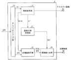
- FIG. 1 is a block diagram illustrating a main configuration of the moving image encoding device 1.
- the moving image encoding apparatus 1 includes an image encoding unit (AVC encoding unit) 11, an image decoding unit (AVC decoding unit) 12, a distance image encoding unit 20, and a packaging unit 28. It is the composition which includes.
- the distance image encoding unit 20 includes an image division processing unit 21, a distance image division processing unit (image dividing unit) 22, a distance value correcting unit 23, a numbering unit (representative value determining unit) 24, and a distance value encoding. Part (adaptive encoding means, output means) 25.
- the image encoding unit 11 The texture image # 1 is encoded by AVC (Advanced Video Coding) coding defined in the H.264 / MPEG-4 AVC standard.
- the encoded data (AVC encoded data) # 11 is output to the image decoding unit 12 and the packaging unit 28.
- the image encoding unit 11 also selects the type of the selected picture (predicted image) (described later) and information for identifying the picture that is the reference destination of the selected picture (the selected picture is a P picture or a B picture) ) Is output to the distance value encoding unit 25.
- the image decoding unit 12 decodes the texture image # 1 ′ from the encoded data # 11 of the texture image # 1 acquired from the image encoding unit 11. Then, the texture image # 1 ′ is output to the image division processing unit 21.
- the decoded texture image # 1 ′ is the same as the image decoded by the moving image decoding device 2 on the receiving side when there is no bit error when transmitting from the moving image encoding device 1. This is different from the texture image # 1. This is because when the original texture image # 1 is AVC-encoded, a quantization error of an orthogonal transform coefficient applied in units called blocks that divide pixels into squares occurs.
- FIG. 2 is a diagram for explaining which picture a certain picture refers to in AVC coding.
- Each picture (201 to 209) in FIG. 2 constitutes a video in this order, and a picture (moving image) is obtained by switching the picture with time.
- a picture means one image (frame image) at a certain discrete time.
- prediction is performed before and after a picture in order to eliminate redundancy in the time direction.
- the prediction means that the screen is divided into square areas (blocks) of a certain size, and each area of the picture to be coded is the one close to the area in other pictures that are temporally related. To find out.
- I picture refers to a picture that is not predicted using another picture.
- a P picture is a picture that uses only a temporally forward picture for prediction.
- a B picture is a picture that uses both forward and backward pictures for prediction. Prediction is performed for each block. For example, in the case of a B picture, up to two pictures can be specified.
- the B picture 201 in FIG. 2 can be decoded only after the I picture 202 as the reference object arrives.
- the B picture 203 whose reference pictures are the I picture 202 and the P picture 205 can be decoded only after the P picture 205 arrives.
- the image decoding unit 12 can perform the decoding process on the B picture that refers to the subsequent picture only after the I picture or the P picture to be referenced arrives. In some cases, an I picture that is a later picture is first decoded and output to the image division processing unit 21.
- the image division processing unit 21 divides the entire area of the texture image into a plurality of segments (areas). Then, the image division processing unit 21 outputs segment information # 21 including position information of each segment to the distance image division processing unit 22.
- the segment position information is information indicating the position of the segment in the texture image # 1.
- the texture image is repeatedly smoothed while leaving edge information. Thereby, the noise which an image has can be removed. Then, adjacent similar colored segments are joined together. However, a segment whose width or height exceeds a predetermined number of pixels is likely to change a distance value within the segment, and is therefore divided so as not to exceed a predetermined number of pixels.
- the texture video can be divided into segments.
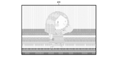
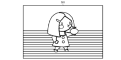
- FIGS. 3 to 5 are diagrams for explaining an example of dividing a texture image.
- the image division processing unit 21 displays the image 401 in FIG. 4. Break into segments.
- the left and right hairs of the girl's head division are drawn in two colors, brown and light brown, and the image division processing unit 21 uses pixels of similar colors such as brown and light brown.
- the closed region is defined as one segment (FIG. 4).
- the image division processing unit 21 separates the skin color region and the pink region from each other. It is defined as a segment (Fig. 4). This is because the skin color and the pink color are not similar (that is, the difference between the skin color pixel value and the pink pixel value exceeds a predetermined threshold value).
- the closed region drawn by the same pattern indicates one segment.
- FIG. 6 shows a distance image 601 corresponding to the image 301 (texture image) in FIG. As shown in FIG. 6, the distance image is an image having a different distance value for each segment.
- the distance image division processing unit 22 When the distance image (frame image) # 2 and the segment information # 21 that are each frame image of the distance video are input, the distance image division processing unit 22 performs the distance image # 2 for each segment in the texture image # 1 ′. A distance value set composed of distance values of each pixel included in the corresponding segment (region) in the center is extracted. Then, the distance image division processing unit 22 generates segment information # 22 in which the distance value set and the position information are associated with each segment from the segment information # 21. Then, the generated segment information # 22 is output to the distance value correction unit 23.
- the distance image division processing unit 22 refers to the input segment information # 21, identifies the position of each segment in the texture image # 1 ′, and is the same as the segment division pattern in the texture image # 1 ′. In this division pattern, the distance image # 2 is divided into a plurality of segments. Therefore, the segment division pattern in the texture image # 1 ′ and the segment division pattern in the distance image # 2 are the same.
- the distance value correction unit 23 calculates the mode value as the representative value # 23a from the distance value set of the segment included in the segment information # 22 for each segment of the distance image # 2. That is, when the segment i in the distance image # 2 includes N pixels, the distance value correcting unit 23 calculates the mode value from the N distance values.
- the distance value correcting unit 23 may calculate an average of N distance values as an average value, or a median value of N distance values or the like as a representative value # 23a instead of the mode value. In addition, when the average value or the median value becomes a decimal value as a result of the calculation, the distance value correcting unit 23 may round the decimal value to an integer value by rounding down, rounding up, or rounding.
- the distance value correcting unit 23 replaces the distance value set of each segment included in the segment information # 22 with the representative value # 23a of the corresponding segment, and outputs it to the number assigning unit 24 as the segment information # 23.
- the reason for calculating the representative value # 23a is as follows. Ideally, all the pixels included in each segment in the distance image # 2 have the same distance value. However, pixels having different distance values in the same segment of the distance image # 2 when the edges of the texture image # 1 and the distance image # 2 are shifted due to, for example, inaccuracy of the distance image # 2. Groups may exist. In such a case, for example, if the distance value of the pixel group having a small pixel value is replaced with the distance value of the pixel group having the maximum pixel value, the distance values in the same segment are all the same, and the distance image # 2 is segmented. It can be rolled into a shape.
- the above processing also has the effect of improving the poor accuracy of the edge portion of the distance image # 2. Will have.
- the number assigning unit 24 associates identifiers having different values with each representative value # 23a included in the segment information # 23. Specifically, the number assigning unit 24 sets the segment number # 24 according to the representative value # 23a and the position information for each set of the position information and the representative value # 23a of the M sets included in the segment information # 23. Associate. Then, the number assigning unit 24 outputs the data in which the segment number # 24 and the representative value # 23a are associated to the distance value encoding unit 25.
- a segment is included in the same segment when the distance values of pixels connected in the vertical or horizontal direction are the same, but even if there are pixels with the same distance value in the diagonal direction, Are not considered to be included in the same segment. That is, the segment is formed by a group of pixels having the same distance value connected in the vertical or horizontal direction.
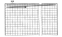
- FIGS. 7 to 9 are diagrams for explaining pixels included in a segment.
- FIGS. 10 to 12 are diagrams for explaining a method of assigning segment number # 24.
- segment number # 24 does not have to overlap in the same image (frame) of the same video, pixels are scanned line by line from the upper left to the lower right of the image (FIG. 10, raster scan). When the number to the segment including the target pixel is not assigned, it is conceivable to assign the number in order from 0.
- segment number # 24 is assigned to the image 501 in FIG. 5 by raster scan
- segment number “0” is assigned to the segment R0 positioned at the head in the raster scan order as shown in FIG.
- segment number “1” is assigned to the segment R1 that is positioned second in the raster scan order.
- segment numbers “2” and “3” are assigned to the third and fourth segments R2 and R3, respectively, in the raster scan order.
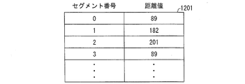
- the distance value encoding unit 25 performs compression encoding processing on the data (segment table 1201) in which the segment number # 24 and the representative value # 23a are associated, and the obtained encoded data (image encoded data) # 25. Is output to the packaging unit 28.
- the distance value is expressed in 256 stages, and the data in which the segment number # 24 and the representative value # 23a are associated with each other is as shown in FIG. It can be expressed as a numerical sequence 1301.
- Adaptive compression coding is a coding process that creates a correspondence table (codebook) between codewords and pre-coding values (sequential pattern) during the compression process, and adaptively updates the codebook. It refers to the method. This is a suitable method when the occurrence probability of each value before encoding is not known.
- static compression encoding If the occurrence probability of each value before encoding is known, encoding based on this occurrence probability can be performed, and this is called static compression encoding.
- static compression coding In order to perform static compression coding, first, in order to obtain the occurrence probability of each value, it is necessary to scan the sequence once to the end, count the frequency of each value, and calculate the occurrence probability of each value. Then, static compression encoding is performed based on the occurrence probability. Therefore, static compression coding has a drawback in that it takes time to process because it is necessary to scan several sequences in order to determine the occurrence probability. Also, since it is necessary to perform decoding corresponding to the encoding method in the decoding side apparatus, the decoding side apparatus similarly takes time for processing.
- adaptive compression coding (adaptive coding) is adopted.
- Adaptive compression coding methods include Huffman coding classified as entropy coding and an adaptive entropy coding method that adaptively updates codebooks (event occurrence probability tables) of arithmetic coding methods.
- codebooks event occurrence probability tables
- Various schemes have been proposed.
- LZW Lempel-Ziv-Welch
- the LZW system is an encoding system developed by Terry Welch as an example of an implementation of the LZ78 encoding system announced by Abraham Lempel and Jacob Ziv in 1978.
- this method paying attention to the pattern in which values are arranged, a newly appearing pattern is sequentially registered in the code book and at the same time a code word is output. On the decoding side, a new pattern is registered in the codebook and decoded based on the received codeword in the same manner as the code side, whereby the original sequence can be completely reproduced. Therefore, this method is a so-called lossless encoding method in which information is not lost by encoding.
- This encoding method is one of the encoding methods having excellent compression efficiency, and is widely used practically in image compression and the like.
- FIG. 14 shows this LZW algorithm.
- the LZW method is an encoding method developed for compressing a character string
- the expression assumes a case where the character string is compressed.
- the character string can be expressed by a binary (bit) sequence of several digits, this algorithm can be applied to the numerical sequence 1301 of the distance value as it is.
- the code book is initialized and all single characters are registered in the code book (S51). For example, if only three letters a, b, and c of the alphabet are used, these three alphabets are registered in the code book, and 0 is assigned to a, 1 is assigned to b, and 2 is assigned to c.
- the first character of the character string to be encoded is read and assigned to ⁇ ( ⁇ is a variable) (S52). Further, the next one character is read and assigned to K (K is a variable) (S53). Then, it is further determined whether or not there is an input character string (S54). If there is no further input character string (NO in S54), the code word corresponding to the character string stored in ⁇ is output and the process ends (S55). On the other hand, if there are more input character strings (YES in S54), it is determined whether or not the character string ⁇ K exists in the code book (S56).
- the LZW algorithm As can be seen from this algorithm, in the LZW method, as the same pattern is included in the character string to be encoded, the pattern portion can be replaced with a single codeword, so that significant compression is possible. It becomes.
- each codeword included in the output codeword string 1601 is converted into a 9-digit binary value as shown in FIG. 17 and output to the packaging unit 28 as a binary string 1701.
- the code word “89” is converted into a binary “001011001”
- the code word “182” is converted into a binary “010110110”, and so on.
- a binary value of 9 digits is used as a value representing each code word.
- the code book becomes larger as the encoding progresses, if the number of code words exceeds 512, 2 digits of 9 digits are used. It cannot be expressed with a value.
- the LZW method has a rule that the size of the codebook increases by 1 at the timing when the code word is output, so the number of digits can be determined on the decoding side. Therefore, if the decoding side counts the number of codewords to be received, it is possible to determine the number of digits at each time point.
- the codebook size increases as the coding continues, so it is necessary to limit the codebook size at some point.
- the codebook maximum size is determined in advance, and when the codebook size reaches the specified size, the codebook is reset to the initial value, or the newest one in order from the pattern with the longest unused period
- LZT method is a method of replacing the Here, it is assumed that the LZT method is used.
- the number sequence 1301 of each picture moving back and forth in time includes many of the same distance value and its appearance pattern.
- the distance value encoding unit 25 further increases the compression efficiency by reusing the codebook 1501 generated by the LZT method between temporally previous and subsequent pictures or between different viewpoint images.
- the image encoding unit 11 encodes the first texture image as an I picture
- information indicating that the I picture has been selected and the distance image segment table 1201 corresponding to the texture image include the distance value code.
- the distance value encoding unit 25 creates a code book 1501 from the segment table 1201 according to the algorithm described above, and converts a binary string 1701 obtained by converting each codeword of the codeword string 1601 into a 9-digit binary value. Output.
- the distance value encoding unit 25 stores the created code book 1501 until the next picture is processed.
- the image encoding unit 11 encodes the second texture image as, for example, a P picture
- information indicating that the P picture has been selected information indicating which picture was referenced, the texture image
- the corresponding distance image segment table 1201 is input to the distance value encoding unit 25.
- this P picture refers to the previous I picture.
- AVC encoding in the case of a B picture, since up to two reference destinations are permitted, there may be two reference destinations. In this case, information on both reference destinations is input.
- the distance value encoding unit 25 creates the code book 1501 from the segment table 1201, the previous code book 1501 stored is used as the initial code book.
- the previous codebook 1501 patterns that are frequently used in the previous picture are already registered, so that efficient compression coding can be performed from the first stage.
- the codebook size is large from the beginning, the number of digits representing each codeword increases from the first stage, and the amount of data increases. Therefore, by using the LZT codebook reduction method described above, even if a set of codewords and corresponding patterns is deleted from a codeword having a long unused period until it reaches a predetermined size (for example, 512). Good. Since at least 9 bits (binary 9 digits) are used to represent each codeword, the amount of information to be transmitted even if 512 codebook sizes from 0 to 511 are held from the beginning. Will not change.
- the codebook size may be reduced every time an I frame is generated. Further, for AVC encoding, an IDR picture, which is a special picture for refreshing the decoding operation on the decoding side, is prepared, and the codebook may be reduced at the timing when the IDR picture is generated.
- header information indicating the coding mode of the entire picture called PPS (Picture Parameter Set) is expanded, and a flag (reduced information) indicating whether or not to reduce the codebook size is inserted into the decoding side. Then, code book size reduction processing may be performed based on this flag.
- PPS Picture Parameter Set
- the image encoding unit 11 selects a texture image to be encoded as a B picture and there are two pictures to be referenced, for example, the following rule is applied to determine a picture for reusing the codebook do it. 1. The picture with the larger area of the block to be referenced is selected. 2. If the area of the block to be referenced is the same, the picture that is closer in time is selected. 3. If they are close in time, a picture earlier in time than the picture to be encoded is selected.
- the distance value encoding unit 25 increases the efficiency of compression encoding by reusing a similar codebook in LZT encoding.
- the period for holding the codebook may be set to 0 to 16 frames, which can be specified as the maximum value of the reference frame, for example, and if an IDR frame arrives, the codebook of the past is saved. It may be configured to be discarded.
- the packaging unit 28 associates the encoded data # 11 of the texture image # 1 and the encoded data # 25 of the distance image # 2 and outputs the encoded data # 28 to the video decoding device 2.
- the packaging unit 28 is H.264.
- the texture image encoded data # 11 and the distance image encoded data # 25 are integrated.
- FIG. 18 is a diagram schematically showing the configuration of the NAL unit 1801. As shown in FIG. 18, the NAL unit 1801 is composed of three parts: a NAL header 1802, an RBSP 1803, and an RBSP trailing bit 1804.
- the RBSP 1803 contains encoded data # 11 and encoded data # 25, which are encoded data.
- the RBSP trailing bit 1804 is an adjustment bit for specifying the last bit position of the RBSP 1803.
- the moving picture encoding apparatus 1 is an H.264 standard.
- the texture image # 1 is encoded using AVC encoding defined in the H.264 / MPEG-4 AVC standard, but the present invention is not limited to this. That is, the image encoding unit 11 of the moving image encoding apparatus 1 may encode the texture image # 1 using another encoding method such as MPEG-2 or MPEG-4.
- FIG. 19 is a flowchart showing the operation of the moving image encoding apparatus 1.
- the operation of the moving image encoding apparatus 1 described here is an operation of encoding a texture image and a distance image of the t frame from the head in a moving image including a large number of frames. That is, the moving image encoding apparatus 1 repeats the operation described below as many times as the number of frames of the moving image in order to encode the entire moving image.
- each data # 1 to # 28 is interpreted as data of the t-th frame.
- the image encoding unit 11 and the distance image division processing unit 22 respectively receive the texture image # 1 and the distance image # 2 from the outside of the moving image encoding device 1 (S1).
- the texture image # 1 and the distance image # 2 received from the outside are correlated with each other in the content of the image, as can be seen, for example, by comparing the texture image of FIG. 3 and the distance image of FIG. is there.
- the image encoding unit 11 The texture image # 1 is encoded by the AVC encoding method stipulated in the H.264 / MPEG-4 AVC standard, and the obtained texture image encoded data # 11 is transmitted to the packaging unit 28 and the image decoding unit 12.
- Output (S2) In step S ⁇ b> 2, the image encoding unit 11 outputs the reference picture to the distance value encoding unit 25 when the selected picture type and the selected picture are a B picture or a P picture.
- the image decoding unit 12 decodes the texture image # 1 ′ from the encoded data # 11 and outputs it to the image division processing unit 21 (S3). Thereafter, the image division processing unit 21 defines a plurality of segments from the input texture image # 1 ′ (S4).
- the image division processing unit 21 generates segment information # 21 including position information of each segment, and outputs it to the distance image division processing unit 22 (S5).
- the position information of the segment for example, each coordinate value of the pixel group located at the boundary with the other segment of the segment can be cited. That is, when each segment is defined from the texture image of FIG. 3, the coordinate value of each coordinate located in the contour portion of the closed region in FIG. 5 becomes the position information of the segment.
- the distance image division processing unit 22 divides the input distance image # 2 into a plurality of segments. Then, the distance image division processing unit 22 extracts a distance value of each pixel included in the segment as a distance value set for each segment of the distance image # 2. Furthermore, the distance image division processing unit 22 associates the distance value set extracted from the corresponding segment with the position information of each segment included in the segment information # 21. Then, the distance image division processing unit 22 outputs the segment information # 22 obtained thereby to the distance value correction unit 23 (S6, image division step).
- the distance value correction unit 23 calculates a representative value # 23a from the distance value set of the segment included in the segment information # 22 for each segment of the distance image # 2. Then, each of the distance value sets included in the segment information # 22 is replaced with the representative value # 23a of the corresponding segment, and is output to the number assigning unit 24 as the segment information # 23 (S7, representative value determining step).
- the number assigning unit 24 associates the representative value # 23a with the segment number # 24 corresponding to the position information for each set of the position information and the representative value # 23a included in the segment information # 23, and sets M sets The representative value # 23a and the segment number # 24 are output to the distance value encoding unit 25 (S8).
- the distance value coding unit 25 performs coding processing on the input representative value # 23a and segment number # 24, and outputs the obtained coded data # 25 to the packaging unit 28 (S9, adaptive) Encoding step).
- the packaging unit 28 integrates the encoded data # 11 output from the image encoding unit 11 in step S2 and the encoded data # 25 output from the distance value encoding unit 25 in step S9.
- the encoded data # 28 is output to the video decoding device 2 (S10).
- the video decoding device 2 decodes the texture image # 1 ′ and the distance image # 2 ′ from the encoded data # 28 transmitted from the video encoding device 1 described above. Then, the decoded texture image # 1 ′ and distance image # 2 ′ are output as frame images to a device constituting the moving image.
- FIG. 20 is a block diagram illustrating a main configuration of the video decoding device 2.
- the moving image decoding apparatus 2 includes an image decoding unit 12, an image division processing unit 21 ′, an unpackaging unit (acquisition unit) 31, a distance value decoding unit (adaptive decoding unit) 32, and a distance.
- a value adding unit (image generating means) 33 is included.
- the unpackaging unit 31 extracts the encoded data # 11 of the texture image # 1 and the encoded data # 25 of the distance image # 2 from the encoded data # 28.
- the encoded data # 11 of the texture image # 1 is output to the image decoding unit 12, and the encoded data # 25 of the distance image # 2 is output to the distance value decoding unit 32.
- the image decoding unit 12 decodes the texture image # 1 ′ from the encoded data # 11.
- the image decoding unit 12 is the same as the image decoding unit 12 included in the moving image encoding device 1. That is, the image decoding unit 12 is configured to transmit the encoded data # 28 from the moving image encoding apparatus 1 to the moving image decoding apparatus 2 as long as no noise is mixed in the encoded data # 28.
- the texture image # 1 ′ having the same content as the texture image decoded by the image decoding unit 12 is decoded. Then, the decoded texture image # 1 ′ is output.
- the image decoding unit 12 outputs the decoded picture type of the texture image # 1 ′ and the reference picture information to the distance value decoding unit 32.
- the image division processing unit 21 ′ divides the entire area of the texture image # 1 ′ into a plurality of segments (areas) using the same algorithm as the image division processing unit 21 of the moving image encoding device 1. Then, the image division processing unit 21 ′ outputs segment information # 21 ′ including the position information of each segment to the distance value giving unit 33.
- the distance value decoding unit 32 decodes the representative value # 23a and the segment number # 24 (decoded data) from the encoded distance image encoded data # 25. Thereby, the sequence 1301 of FIG. 13 encoded by the distance value encoding unit 25 of the moving image encoding apparatus 1 is decoded.
- the distance value decoding unit 32 executes the generated codebook for a predetermined period (for example, the longest time width of temporal backward prediction (which back picture is allowed to be referenced), until an IDR picture is received, etc.) ,Hold.
- the image decoding unit 12 is required to hold the picture for the same time. Since this can be determined by the reception information in the AVC format, it is determined by this. When a picture that reuses the retained codebook is received, decoding is performed using the codebook.
- which codebook is to be reused is determined according to the same algorithm as that used in the encoding by the distance value encoding unit 25 based on the reference destination information input from the image decoding unit 12.
- the segment table 1201 of FIG. 12 is decoded.
- the segment table 1201 is output to the distance value assigning unit 33.
- the distance value assigning unit 33 Based on the input representative value # 23a and segment number # 24, the distance value assigning unit 33 applies a pixel value (distance value), which is a representative value of the segment, to the pixel included in each segment. Restore 2 '. Then, the restored distance image # 2 ′ is output.
- texture image # 1 and distance image # 2 can be decoded.
- the texture image screen is divided into segments by the following method
- the input texture image is an image of 1024 ⁇ 768 dots
- about several thousand segments for example, 3000 to 5000 segments
- the image division processing unit 21 calculates an average value calculated from the pixel values of the pixel group included in the segment and a segment adjacent to the segment from the input texture image # 1 ′. A plurality of segments whose difference from the average value calculated from the pixel values of the included pixel group is equal to or less than a predetermined threshold value are defined.
- FIG. 26 is a flowchart showing an operation in which the video encoding device 1 defines a plurality of segments based on the above algorithm.
- FIG. 27 is a flowchart showing a subroutine of segment combination processing in the flowchart of FIG.
- the image division processing unit 21 performs an independent segment (provisional segment) for each of all the pixels included in the texture image in the initialization step in the figure with respect to the texture image subjected to the smoothing process.
- the pixel value itself of the corresponding pixel is set as an average value (average color) of all the pixel values in each provisional segment (S41).
- segment combination processing step (S42) the process proceeds to the segment combination processing step (S42), and the provisional segments having similar colors are combined.
- This segment combining process will be described in detail below with reference to FIG. 27, and this combining process is repeated until the combination is not performed.
- the image division processing unit 21 performs the following processing (S51 to S55) for all provisional segments.
- the image division processing unit 21 determines whether or not the height and width of the temporary segment of interest are both equal to or less than a threshold value (S51). If it is determined that both are equal to or lower than the threshold (YES in S51), the process proceeds to step S52. On the other hand, when it is determined that any one is larger than the threshold value (NO in S51), the process of step S51 is performed for the temporary segment to be focused next. Note that the temporary segment to be noted next may be, for example, a temporary segment positioned next to the temporary segment of interest in the raster scan order.
- the image division processing unit 21 selects a temporary segment having an average color closest to the average color of the temporary segment of interest among the temporary segments adjacent to the temporary segment of interest (S52).
- a temporary segment having an average color closest to the average color of the temporary segment of interest among the temporary segments adjacent to the temporary segment of interest (S52).
- an index for judging the closeness of colors for example, the Euclidean distance between vectors when the three RGB values of pixel values are regarded as a three-dimensional vector can be used.
- a pixel value of each segment an average value of all pixel values included in each segment is used.
- the image division processing unit 21 determines whether or not the proximity of the temporary segment of interest and the temporary segment that is determined to have the closest color is equal to or less than a certain threshold value. (S53). If it is determined that the value is larger than the threshold value (NO in S53), the process of step S51 is performed for the temporary segment that should be noted next. On the other hand, if it is determined that the value is equal to or less than the threshold value (NO in S53), the process proceeds to step S54.
- the image division processing unit 21 converts two provisional segments (provisional segments determined to be closest in color to the provisional segment of interest) into one provisional segment. (S54).
- the number of provisional segments is reduced by 1 by the process of step S54.
- step S54 the average value of the pixel values of all the pixels included in the converted target segment is calculated (S55). If there is a segment that has not yet been subjected to the processing of steps S51 to S55, the processing of step S51 is performed for the temporary segment to be noticed next.
- step S43 After completing the processes of steps S51 to S55 for all the provisional segments, the process proceeds to the process of step S43.
- the image division processing unit 21 compares the number of provisional segments before the process of step S42 with the number of provisional segments after the process of step S42 (S43).
- the process returns to step S42.
- the image division processing unit 21 defines each current temporary segment as one segment.
- the input texture image is an image of 1024 ⁇ 768 dots, it can be divided into about several thousand (for example, 3000 to 5000) segments.
- the segment is used to divide the distance image. Therefore, if the size of the segment becomes too large, various distance values are included in one segment, resulting in a pixel having a large error from the representative value, and the encoding accuracy of the distance image decreases. Therefore, in the present invention, the process of step S51 is not essential, but it is desirable to prevent the segment size from becoming too large by limiting the segment size as in step S51.
- the number of segments can be made significantly smaller than the number of processing units for orthogonal transformation. Further, since the distance value in each segment is constant, it is not necessary to perform orthogonal transform, and the distance value can be transmitted with 8-bit information. Further, in the present embodiment, it is possible to further improve the compression efficiency by performing an adaptive compression encoding method and reusing the code book. Therefore, in this embodiment, the compression efficiency can be greatly improved as compared with the case where the texture video (image) and the distance video (image) are each encoded by the AVC encoding method.
- FIG. 21 is a flowchart showing the operation of the video decoding device 2.
- the operation of the moving image decoding apparatus 2 described here is an operation of decoding a texture image and a distance image of the t-th frame from the top in a three-dimensional moving image including a large number of frames. That is, the moving image decoding apparatus 2 repeats the operation described below as many times as the number of frames of the moving image in order to decode the entire moving image.
- each data # 1 to # 28 is interpreted as data at the t-th frame.
- the unpackaging unit 31 extracts the encoded data # 11 of the texture image and the encoded data # 25 of the distance image from the encoded data # 28 received from the moving image encoding device 1. Then, the unpackaging unit 31 outputs the encoded data # 11 to the image decoding unit 12, and outputs the encoded data # 25 to the distance value decoding unit 32 (S21).
- the image decoding unit 12 decodes the texture image # 1 ′ from the input encoded data # 11, and sends it to the image division processing unit 21 ′ and a stereoscopic video display device (not shown) outside the moving image decoding device 2. Output (S22). Further, the image decoding unit 12 outputs the picture information # 11A report indicating the type of the selected picture and the reference picture to the distance value decoding unit 32.
- the image division processing unit 21 ′ defines a plurality of segments using the same algorithm as the image division processing unit 21 of the moving image encoding device 1.
- the image division processing unit 21 ′ replaces the pixel value of each pixel included in each segment with a representative value in the raster scan order in the texture image # 1 ′, so that the segment identification image # 21 ′ is generated.
- the image division processing unit 21 ′ outputs the segment identification image # 21 ′ to the distance value providing unit 33 (S23).
- the distance value decoding unit 32 decodes the binary string 1701 described above from the encoded data # 25 of the encoded distance image. Further, the distance value decoding unit 32 decodes the segment number and the representative value # 23a from the binary string 1701. Then, the distance value decoding unit 32 outputs the obtained representative value # 23a and segment number # 24 to the distance value giving unit 33 (S24, adaptive decoding step).
- the distance value assigning unit 33 converts the pixel values of all the pixels in the segment identification image # 21 into the representative value # 23a included in the segment based on the input representative value # 23a and the segment number # 24. Thus, the distance image # 2 ′ is decoded. Then, the distance value assigning unit 33 outputs the distance image # 2 ′ to the above-described stereoscopic video display device (S25, image generation step).
- the distance image # 2 ′ decoded by the distance value assigning unit 33 in step S25 is generally the distance image # input to the video encoding device 1.
- the distance image approximates to 2.
- the distance image # 2 is the same as the image obtained by changing the distance value of a very small part included in the segment in the distance image # 2 to the representative value in the segment. It can be said that the distance image # 2 is approximate.
- the moving image transmission system including the moving image encoding device 1 and the moving image decoding device 2 described above also exhibits the above-described effects.
- This embodiment is different from the first embodiment in that there are a plurality of viewpoints of texture images and distance images corresponding to the texture images. That is, the moving image encoding apparatus 1A according to the present embodiment performs the texture image and distance image encoding processing using the same encoding method as the moving image encoding apparatus 1 of the first embodiment. This is different from the moving image encoding apparatus 1 in that a plurality of sets of texture images and distance images are encoded per frame.
- the plurality of sets of texture images and distance images are images of subjects simultaneously captured by cameras and ranging devices installed at a plurality of locations so as to surround the subject. That is, the plurality of sets of texture images and distance images are images for generating a free viewpoint image. Also, each set of texture image and distance image includes camera parameters such as camera position, direction, and focal length information as metadata, along with actual data of the texture image and distance image of the set.
- FIG. 22 is a block diagram showing a main configuration of the moving picture encoding apparatus 1A according to the present embodiment.
- the moving image encoding apparatus 1A includes an image encoding unit (MVC encoding unit) 11A, an image decoding unit (MVC decoding unit) 12A, a distance image encoding unit 20A, and a packaging unit 28 ′. It has.
- the distance image encoding unit 20A includes an image division processing unit 21, a distance image division processing unit 22, a distance value correction unit 23, a number assigning unit 24, and a distance value encoding unit (adaptive encoding unit and output unit). 25A.
- the image encoding unit 11A performs the same encoding as the image encoding unit 11 described above, but differs in that it compresses and encodes images from a plurality of viewpoints. Specifically, the image encoding unit 11A performs encoding using MVC (Multiview Video Coding).
- MVC Multiview Video Coding
- AVC used in the first embodiment is a standard for compressing and encoding video (image) from one viewpoint
- MVC is a standard for compressing and encoding multi-view video (image). is there. Therefore, the encoded data # 11 output from the image encoding unit 11A is MVC encoded data.
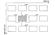
- MVC coding performs the prediction described in the first embodiment even between viewpoints in order to eliminate redundancy between viewpoints. This will be specifically described with reference to FIG. FIG. 23 is a diagram for explaining MVC coding.
- an image is predicted in block units from the time direction and the viewpoint direction (spatial direction).
- the images 2303 and 2305 can be referred to as images in the time direction
- the images 2302 and 2304 can be referred to as images in the viewpoint direction.
- the same method can be used to eliminate the redundancy between images in the time direction and the redundancy between images in the spatial direction.
- a reference destination image is generated in the spatial direction as in the temporal direction.
- Up to two reference images in the spatial direction can be referred to.
- the image decoding unit 12A decodes the texture image # 1 ′ from the encoded data # 11 of the texture image # 1 obtained from the image encoding unit 11A. Then, the texture image # 1 ′ is output to the image division processing unit 21.
- the distance value encoding unit 25A performs compression encoding processing on the data in which the segment number # 24 and the representative value # 23a are associated, and obtains the obtained encoded data # 25. Output to the packaging unit 28 '.
- FIG. 24 is a flowchart illustrating a flow of processing in which the distance value encoding unit 25A determines a reference image.
- the reference image with a small viewpoint number is selected (S84).
- a configuration is given in which priority is given to images in the time direction, but a configuration in which images in the spatial direction are given priority may be used.
- the cameras are generally arranged at intervals of several centimeters, and the distance values of the distance images corresponding to the cameras are almost equal. Therefore, it can be expected that the distance value appearing in the distance image and the appearance pattern thereof are similar between pictures of different viewpoints. Therefore, in the distance value encoding unit 25A as well as the distance value encoding unit 25 of the above embodiment, the code book when the distance value is adaptively compressed and encoded with respect to the reference image is stored and reused. By doing so, the efficiency of compression encoding can be improved.
- the packaging unit 28 ' encodes the encoded data # 11 (-1 to -N) of the texture images # 1-1 to # 1-N and the encoded data # 25 (- 1 to -N) to generate encoded data # 28 '. Then, the packaging unit 28 ′ transmits the generated encoded data # 28 ′ to the video decoding device 2A.
- FIG. 25 is a block diagram showing a main configuration of the moving picture decoding apparatus 2A.
- the moving image decoding apparatus 2A includes an image decoding unit 12A, an image division processing unit 21 ′, an unpackaging unit 31 ′, a distance value decoding unit 32A, and a distance value giving unit 33. .
- the unpackaging unit 31' When receiving the encoded data 28 ', the unpackaging unit 31' extracts the encoded data # 11 (-1 to -N) and the encoded data # 25 (-1 to -N) and encodes them. Data # 11 is output to the image decoding unit 12, and encoded data # 25 is output to the distance value decoding unit 32.
- the reference image is determined according to the algorithm shown in FIG. 24, the distance value is decoded by reusing the code book, and the distance image is restored.
- the moving image decoding apparatus 2 and the moving image encoding apparatus 1 described above can be used by being mounted on various apparatuses that perform transmission, reception, recording, and reproduction of moving images.
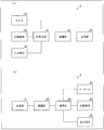
- FIG. 28A is a block diagram showing a configuration of a transmission apparatus A equipped with the moving picture encoding apparatus 1.
- the transmitting apparatus A encodes a moving image, obtains encoded data, and modulates a carrier wave with the encoded data obtained by the encoding unit A1.
- a modulation unit A2 that obtains a modulation signal by the transmission unit A2 and a transmission unit A3 that transmits the modulation signal obtained by the modulation unit A2.
- the moving image encoding apparatus 1 described above is used as the encoding unit A1.
- the transmission apparatus A has a camera A4 that captures a moving image, a recording medium A5 that records the moving image, and an input terminal A6 for inputting the moving image from the outside as a supply source of the moving image input to the encoding unit A1. May be further provided.
- FIG. 28A the configuration in which the transmission apparatus A includes all of these is illustrated, but a part of the configuration may be omitted.
- the recording medium A5 may be a recording of a non-encoded moving image, or a recording of a moving image encoded by a recording encoding scheme different from the transmission encoding scheme. It may be a thing. In the latter case, a decoding unit (not shown) for decoding the encoded data read from the recording medium A5 according to the recording encoding method may be interposed between the recording medium A5 and the encoding unit A1.
- FIG. 28 (b) is a block diagram showing the configuration of the receiving device B on which the moving image decoding device 2 is mounted.
- the receiving apparatus B includes a receiving unit B1 that receives a modulated signal, a demodulating unit B2 that obtains encoded data by demodulating the modulated signal received by the receiving unit B1, and a demodulating unit.
- a decoding unit B3 that obtains a moving image by decoding the encoded data obtained by B2.
- the moving picture decoding apparatus 2 described above is used as the decoding unit B3.
- the receiving apparatus B has a display B4 for displaying a moving image, a recording medium B5 for recording the moving image, and an output terminal for outputting the moving image as a supply destination of the moving image output from the decoding unit B3.
- B6 may be further provided.
- FIG. 28B illustrates a configuration in which the receiving apparatus B includes all of these, but some of them may be omitted.
- the recording medium B5 may be for recording an unencoded moving image, or is encoded by a recording encoding method different from the transmission encoding method. May be.
- an encoding unit (not shown) that encodes the moving image acquired from the decoding unit B3 in accordance with the recording encoding method may be interposed between the decoding unit B3 and the recording medium B5.
- the transmission medium for transmitting the modulation signal may be wireless or wired.
- the transmission mode for transmitting the modulated signal may be broadcasting (here, a transmission mode in which the transmission destination is not specified in advance) or communication (here, transmission in which the transmission destination is specified in advance). Refers to the embodiment). That is, the transmission of the modulation signal may be realized by any of wireless broadcasting, wired broadcasting, wireless communication, and wired communication.
- a terrestrial digital broadcast broadcasting station (such as broadcasting equipment) / receiving station (such as a television receiver) is an example of a transmitting device A / receiving device B that transmits and receives a modulated signal by wireless broadcasting.
- a broadcasting station (such as broadcasting equipment) / receiving station (such as a television receiver) for cable television broadcasting is an example of a transmitting device A / receiving device B that transmits and receives a modulated signal by cable broadcasting.
- a server workstation etc.
- Client television receiver, personal computer, smart phone etc.
- VOD Video On Demand
- video sharing service using the Internet is a transmitting device for transmitting and receiving modulated signals by communication.
- a / reception device B usually, either wireless or wired is used as a transmission medium in a LAN, and wired is used as a transmission medium in a WAN.
- the personal computer includes a desktop PC, a laptop PC, and a tablet PC.
- the smartphone also includes a multi-function mobile phone terminal.
- the video sharing service client has a function of encoding a moving image captured by the camera and uploading it to the server. That is, the client of the video sharing service functions as both the transmission device A and the reception device B.
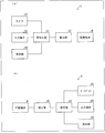
- FIG. 29A is a block diagram showing a configuration of a recording apparatus C equipped with the moving picture decoding apparatus 2 described above.
- the recording device C encodes a moving image to obtain encoded data, and writes the encoded data obtained by the encoding unit C1 to the recording medium M.
- the moving image encoding device 1 described above is used as the encoding unit C1.
- the recording medium M may be of a type built in the recording device C, such as (1) HDD (Hard Disk Drive) or SSD (Solid State Drive), or (2) SD memory. It may be of the type connected to the recording device C, such as a card or USB (Universal Serial Bus) flash memory, or (3) DVD (Digital Versatile Disc) or BD (Blu-ray Disk: registration) (Trademark) or the like may be mounted on a drive device (not shown) built in the recording apparatus C.
- the recording apparatus C receives a moving image as a supply source of the moving image input to the encoding unit C1, a camera C3 that captures the moving image, an input terminal C4 for inputting the moving image from the outside, and the moving image.
- the receiving section C5 may be further provided.
- FIG. 29A illustrates a configuration in which the recording apparatus C includes all of these, but some of them may be omitted.
- the receiving unit C5 may receive an unencoded moving image, or receives encoded data encoded by a transmission encoding method different from the recording encoding method. You may do. In the latter case, a transmission decoding unit (not shown) that decodes encoded data encoded by the transmission encoding method may be interposed between the reception unit C5 and the encoding unit C1.
- Examples of such a recording device C include a DVD recorder, a BD recorder, and an HD (Hard Disk) recorder (in this case, the input terminal C4 or the receiving unit C5 is a main source of moving images). Further, a camcorder (in this case, the camera C3 is a main source of moving images), a personal computer (in this case, the receiving unit C5 is a main source of moving images), a smartphone (in this case, the camera C3 or The receiving unit C5 is a main source of moving images) is an example of such a recording apparatus C.
- FIG. 29 (b) is a block diagram showing the configuration of the playback device D equipped with the above-described video decoding device 2. As shown in FIG. 29 (b), the playback device D obtains a moving image by decoding the read data D1 read by the read unit D1 and the read data read by the read unit D1. And a decoding unit D2. The moving picture decoding apparatus 2 described above is used as the decoding unit D2.
- the recording medium M may be of a type built in the playback device D such as (1) HDD or SSD, or (2) such as an SD memory card or USB flash memory. It may be of a type connected to the playback device D, or (3) may be loaded into a drive device (not shown) built in the playback device D, such as DVD or BD. Good.
- the playback device D has a display D3 for displaying a moving image, an output terminal D4 for outputting the moving image to the outside, and a transmitting unit for transmitting the moving image as a supply destination of the moving image output by the decoding unit D2.
- D5 may be further provided.
- FIG. 29B illustrates a configuration in which the playback apparatus D includes all of these, but a part of the configuration may be omitted.
- the transmission unit D5 may transmit a non-encoded moving image, or transmits encoded data encoded by a transmission encoding method different from the recording encoding method. You may do. In the latter case, an encoding unit (not shown) that encodes a moving image with a transmission encoding method may be interposed between the decoding unit D2 and the transmission unit D5.
- Examples of such a playback device D include a DVD player, a BD player, and an HDD player (in this case, an output terminal D4 to which a television receiver or the like is connected is a main moving image supply destination).
- a television receiver in this case, the display D3 is a main destination of moving images
- a desktop PC in this case, the output terminal D4 or the transmission unit D5 is a main destination of moving images
- a laptop or tablet PC in this case, the display D3 or the transmission unit D5 is a main destination of moving images
- a smartphone in this case, the display D3 or the transmission unit D5 is a main destination of moving images)
- the moving image coding apparatus 1 includes the distance image division processing unit 22 that divides each frame image of a moving image into a plurality of regions, and the representative of each region divided by the distance image division processing unit 22.
- the distance image division processing unit 22 By adaptively updating a codebook in which a sequence pattern and a code word are associated with a number sequence in which a value is determined and a number sequence in which the representative values determined by the number allocation unit 24 are arranged in a predetermined order
- a distance value encoding unit 25 that performs adaptive encoding for encoding and generates encoded data of the frame image.
- the distance value encoding unit 25 serves as an initial codebook of the codebook to be updated. In this case, a codebook created when adaptively encoding a frame image other than the frame image to be adaptively encoded is used.
- the moving image encoding apparatus is a moving image encoding apparatus that encodes a moving image, and an image dividing unit that divides each frame image of the moving image into a plurality of regions;
- a representative value determining means for determining a representative value of each area divided by the image dividing means, and a number sequence pattern for a number sequence in which the representative values determined by the representative value determining means are arranged in a predetermined order for each frame image.
- adaptive coding means for adaptively updating and coding a codebook in which codewords are associated with each other and generating coded data of the frame image, and the adaptive coding means
- the encoding means uses the code book that has been updated when a frame image other than the frame image to be adaptively encoded is adaptively encoded as the codebook to be updated.
- a control method for a moving image encoding device is a control method for a moving image encoding device that encodes a moving image, in which each frame image of the moving image is divided into a plurality of regions.
- Adaptive encoding for adaptively updating and encoding a codebook in which a sequence pattern and a code word are associated, and generating encoded data of the frame image,
- the code book to be updated the code book that has been updated when the frame image other than the frame image to be adaptively encoded is adaptively encoded. It is characterized by using.
- each frame image of a moving image is divided into a plurality of regions, and a representative value of each divided region is determined. Then, for each frame image, adaptive encoding is performed on a numerical sequence in which representative values are arranged in a predetermined order.
- the predetermined order is an order in which the position corresponding to the representative value can be specified in the frame image.
- the order in which any pixel included in each region is first scanned when the frame image is raster scanned can be set as a predetermined order.
- the codebook to be updated can be reused at the time of adaptive coding, so that the efficiency of adaptive coding processing can be improved as compared with the case where the codebook is not reused. . That is, a moving image can be efficiently encoded.
- the adaptive coding means finishes updating when the latest frame image of the frame image to be adaptively coded is adaptively coded as the codebook to be updated.
- a code book may be used.
- the code book that has been updated when the frame image nearest to the frame image to be adaptively encoded is adaptively used is used as the code book to be updated.
- the frame images before and after are likely to be similar. Therefore, the most recent frame image is likely to be similar to the image frame to be encoded, and the number of representative values in each region of the image frame is also likely to be similar.
- the codebook that has been updated when the latest image frame is adaptively encoded has a large number of reusable parts, and the adaptive encoding process can be performed more efficiently.
- the moving image is a moving image of a distance image in which each pixel value indicates a depth value, and includes AVC encoding means for encoding a texture image with AVC (Advanced Video Coding).
- the adaptive encoding means when adaptively encoding the distance image, corresponds to the texture image selected as the prediction image when the AVC encoding means encodes the texture image corresponding to the distance image.
- the code book that has been updated when the range image to be adaptively encoded is used as the code book to be updated may be used.
- the distance image corresponding to the prediction image selected when the texture image corresponding to the distance image is AVC-encoded as the code book to be updated when the distance image is adaptively encoded.
- a codebook that has been updated when adaptive coding is used is used.
- the predicted image selected when the texture image is AVC-encoded is an image similar to the texture image. Therefore, the distance image to be encoded is similar to the distance image corresponding to the predicted image of the texture image corresponding to the distance image.
- the code book that has been updated when a similar distance image is adaptively encoded can be used as the updated codebook, and the adaptive encoding process can be performed more efficiently.
- the moving image is a moving image of a distance image in which each pixel value indicates a depth value
- MVC Multiview Video that encodes a plurality of texture images corresponding to a plurality of viewpoints. Coding
- MVC Multiview Video that encodes a plurality of texture images corresponding to a plurality of viewpoints. Coding
- the adaptive encoding means encodes a texture image corresponding to the distance image when the distance image is adaptively encoded.
- the code book that has been updated when the distance image corresponding to the texture image selected as the predicted image is adaptively encoded may be used as the updated code book.
- the distance image corresponding to the prediction image selected when the texture image corresponding to the distance image is MVC-encoded as the code book to be updated when the distance image is adaptively encoded.
- a codebook that has been updated when adaptive coding is used is used.
- the predicted image selected when the texture image is MVC encoded is an image similar to the texture image. Therefore, the distance image to be encoded is similar to the distance image corresponding to the predicted image of the texture image corresponding to the distance image.
- the code book created when the similar distance image is adaptively encoded can be used as the code book to be updated, and the adaptive encoding process can be performed more efficiently.
- the adaptive encoding means updates when the range image corresponding to the predicted image having the largest area to be referenced is adaptively encoded when there are a plurality of the predicted images.
- the completed code book may be used as the updated code book.
- the code book that has been updated when the distance image corresponding to the predicted image with the largest area to be referenced is adaptively encoded is used as the updated code book.
- the predicted image with the largest area to be referred to is the image most similar to the texture image among the predicted images. Therefore, as a code book to be updated when the distance image is adaptively encoded, among the predicted images of the texture image corresponding to the distance image, the distance image corresponding to the predicted image most similar to the texture image is adaptively encoded. You can use the updated codebook.
- the adaptive encoding means may perform adaptive decoding by updating the codebook after reducing the codebook to be updated to a predetermined size. Good.
- a codebook that has been updated when a frame image different from the frame image to be encoded is adaptively encoded is likely to have increased in size, and can be used as a codebook to be updated as it is. As you go, the size gets bigger.
- the adaptive encoding means reduces the code book to be updated to a predetermined size, so that it is possible to prevent the code book from becoming large and the data amount from increasing.
- the moving image encoding apparatus further comprises output means for outputting the encoded data, and the output means receives reduction information indicating that the adaptive encoding means has reduced the codebook when the codebook is reduced. It may be output together with the encoded data.
- the moving picture decoding apparatus divides each frame image of a moving picture into a plurality of areas, and associates a sequence pattern and a code word with a number sequence in which representative values of each area are arranged in a predetermined order.
- a video decoding device that decodes image encoded data that is encoded data of the frame image that has been subjected to adaptive encoding that is encoded by adaptively updating the attached codebook, the image encoding
- the adaptive decoding means for adaptively updating and decoding the codebook for the data to generate decoded data, the decoded data generated by the adaptive decoding means, and the region Image generating means for generating an image from the information, and the adaptive decoding means adapts image encoded data other than the image encoded data to be adaptively decoded as the codebook to be updated. It is characterized by using a codebook finished updated when decoded.
- control method of the moving picture decoding apparatus divides each frame image of a moving picture into a plurality of areas, and a number sequence pattern and codeword for a number sequence in which representative values of each area are arranged in a predetermined order.
- Is a method for controlling a moving picture decoding apparatus that decodes encoded image data that is encoded data of the frame image that has been subjected to adaptive encoding in which encoding is performed by adaptively updating a codebook associated with Then, adaptive decoding for adaptively updating and decoding the codebook with respect to the image encoded data to generate decoded data, and the decoded data generated in the adaptive decoding step And an image generation step for generating an image from the information indicating the region, and in the adaptive decoding step, encoding that performs adaptive decoding as the codebook to be updated It is characterized by using a codebook finished updated when adaptively decodes the encoded data other than over data.
- a code in which each frame image of a moving image is divided into a plurality of regions, and a number sequence in which representative values of each region are arranged in a predetermined order is associated with a number sequence pattern and a code word.
- the image encoded data that is the encoded data of the frame image that has been subjected to adaptive encoding for adaptively updating and encoding the book is adaptively decoded. Then, an image is generated from the decoded data subjected to adaptive decoding and information indicating the region.
- the codebook to be used for adaptive decoding the codebook that has been updated when the image encoded data other than the image encoded data to be adaptively decoded is adaptively used is used.
- the adaptive decoding means finishes updating when the latest encoded image data of the encoded image to be adaptively decoded is adaptively decoded as the updated codebook.
- a code book may be used.
- the code book that has been updated when the latest frame image of the encoded image data to be adaptively decoded is adaptively used as the codebook to be updated.
- the codebook that has been updated when the latest image encoded data is adaptively decoded has a large number of parts that can be reused, and the adaptive decoding process can be performed more efficiently.
- the moving image is a moving image of a distance image in which each pixel value indicates a depth value, and a texture image corresponding to the distance image is included together with image encoded data of the distance image.
- the adaptive decoding means comprises: acquisition means for acquiring AVC encoded data which is AVC (Advanced Video Coding) encoded data; and AVC decoding means for decoding the AVC encoded data acquired by the acquisition means.
- AVC encoded data is adaptively decoded
- the code book that has been updated when the encoded data is adaptively decoded may be used as the code book to be updated.
- a codebook to be updated when adaptively decoding image encoded data it corresponds to a predicted image selected when AVC encoded data corresponding to the image encoded data is AVC decoded.
- a codebook that has been updated when the image encoded data of the distance image to be adaptively decoded is used.
- the predicted image selected when the AVC encoded data is AVC decoded is an image similar to the texture image when the AVC encoded data is decoded. Therefore, the encoded image data to be decoded is similar to the encoded image data of the distance image corresponding to the predicted image of the AVC encoded data corresponding to the encoded image data.
- a codebook that has been updated when adaptively decoding similar image encoded data can be used as a codebook to be updated, and adaptive decoding processing can be performed more efficiently.
- the moving image is a moving image of a distance image in which each pixel value indicates a depth value, and a texture image corresponding to the distance image is included together with image encoded data of the distance image.
- Acquisition means for acquiring MVC encoded data which is MVC (Multiview Video ⁇ ⁇ Coding) encoded data for encoding a plurality of texture images corresponding to a plurality of viewpoints, and MVC encoded data acquired by the acquisition means.
- the MVC decoding means for decoding, when the adaptive decoding means adaptively decodes the image encoded data, the MVC decoding means decodes the MVC encoded data corresponding to the image encoded data
- the codebook that has been updated when the image coding data of the distance image corresponding to the texture image selected as the predicted image is adaptively decoded is Or it may be used as a codebook new to.
- a code book to be updated when adaptively decoding image encoded data it corresponds to a predicted image selected when MVC encoded data corresponding to the image encoded data is MVC decoded.
- a codebook that has been updated when the image encoded data of the distance image to be adaptively decoded is used.
- the predicted image selected when the MVC encoded data is MVC decoded is an image similar to the texture image when the MVC encoded data is decoded. Therefore, the encoded image data to be decoded is similar to the encoded image data of the distance image corresponding to the predicted image of the MVC encoded data corresponding to the encoded image data.
- a codebook that has been updated when adaptively decoding similar image encoded data can be used as a codebook to be updated, and adaptive decoding processing can be performed more efficiently.
- the adaptive decoding means adaptively decodes the encoded image data of the distance image corresponding to the predicted image having the largest area to be referenced when there are a plurality of the predicted images.
- the code book that has been updated may be used as the code book to be updated.
- the codebook that has been updated when the image encoded data of the distance image corresponding to the predicted image with the largest area to be referenced is adaptively decoded is updated. Used as a code book.
- the predicted image with the largest area to be referred to is the image most similar to the texture image among the predicted images. Therefore, as a codebook that is updated when image-encoded data is adaptively decoded, it is updated when image-encoded data of the distance image corresponding to the predicted image most similar to the texture image is adaptively decoded among the predicted images.
- the completed codebook can be used.
- the adaptive decoding means may perform adaptive decoding by updating the codebook after reducing the codebook to be updated to a predetermined size.
- the code book that has been updated when the image encoded data different from the image encoded data to be decoded is adaptively decoded is likely to have increased in size, and is used as a code book to be updated as it is. As you do, the size will become even larger.
- the adaptive decoding means reduces the code book to be updated to a predetermined size, so that it is possible to prevent the code book from becoming large and increasing the data amount.
- the acquisition unit acquires reduction information indicating that the codebook used for adaptive encoding has been reduced when the image encoded data is adaptively encoded.
- the adaptive decoding unit may reduce the code book used for decoding when the acquisition unit acquires the reduction information.
- the code book when the code book is reduced when encoded, the reduced information indicating the reduction is acquired together with the encoded image data. Therefore, it is possible to recognize that the code book has been reduced during encoding. Therefore, when decoding the encoded image data, the code book can be reduced and used in the same manner as when the encoded image data is encoded.
- the moving image transmission system including the moving image encoding device and the moving image decoding device can achieve the effects described above.
- the moving image encoding device and the moving image decoding device may be realized by a computer.
- the moving image encoding device and the moving image decoding device are operated by causing the computer to operate as the respective means.
- a video encoding device and a video decoding device control program realized by a computer and a computer-readable recording medium on which the control program is recorded also fall within the scope of the present invention.
- each block of the moving image encoding device 1 (1A) and the moving image decoding device 2 (2A), particularly the image encoding unit 11 (11A), the image decoding unit 12, and the distance image encoding unit 20 (20A) Image division processing unit 21 (21 ′), distance image division processing unit 22, distance value correction unit 23, number assigning unit 24, distance value encoding unit 25 (25A)), distance value decoding unit 32, distance value providing unit 33 May be realized in hardware by a logic circuit formed on an integrated circuit (IC chip), or may be realized in software using a CPU (central processing unit).
- the moving image encoding device 1 (1A) and the moving image decoding device 2 (2A) include a CPU that executes instructions of a control program for realizing each function, a ROM (read only memory) that stores the program, A RAM (random access memory) for expanding the program and a storage device (recording medium) such as a memory for storing the program and various data are provided.
- An object of the present invention is to provide program codes (execution format program, intermediate code program, program code) for control programs of the video encoding device 1 (1A) and the video decoding device 2 (2A), which are software for realizing the functions described above.
- a recording medium in which a source program is recorded so as to be readable by a computer is supplied to the moving image encoding device 1 (1A) and the moving image decoding device 2 (2A), and the computer (or CPU or MPU (microprocessor unit)) ) Can also be achieved by reading and executing the program code recorded on the recording medium.
- the recording medium examples include tapes such as a magnetic tape and a cassette tape, a magnetic disk such as a floppy (registered trademark) disk / hard disk, a CD-ROM (compact disk-read-only memory) / MO (magneto-optical) / Discs including optical discs such as MD (Mini Disc) / DVD (digital versatile disc) / CD-R (CD Recordable), IC cards (including memory cards) / optical cards, mask ROM / EPROM (erasable) Programmable read-only memory) / EEPROM (electrically erasable and programmable read-only memory) / semiconductor memory such as flash ROM, or logic circuits such as PLD (Programmable logic device) and FPGA (Field Programmable Gate Array) be able to.
- a magnetic disk such as a floppy (registered trademark) disk / hard disk
- the moving image encoding device 1 (1A) and the moving image decoding device 2 (2A) may be configured to be connectable to a communication network, and the program code may be supplied via the communication network.
- the communication network is not particularly limited as long as it can transmit the program code.
- Internet intranet, extranet, LAN (local area network), ISDN (integrated area services digital area), VAN (value-added area network), CATV (community area antenna television) communication network, virtual area private network (virtual area private network), A telephone line network, a mobile communication network, a satellite communication network, etc. can be used.
- the transmission medium constituting the communication network may be any medium that can transmit the program code, and is not limited to a specific configuration or type.
- IEEE institute of electrical and electronic engineers 1394, USB, power line carrier, cable TV line, telephone line, ADSL (asynchronous digital subscriber loop) line, etc. wired such as IrDA (infrared data association) or remote control , Bluetooth (registered trademark), IEEE 802.11 wireless, HDR (high data rate), NFC (Near Field Communication), DLNA (Digital Living Network Alliance), mobile phone network, satellite line, terrestrial digital network, etc.
- IrDA infrared data association
- Bluetooth registered trademark
- IEEE 802.11 wireless high data rate
- NFC Near Field Communication
- DLNA Digital Living Network Alliance
- mobile phone network satellite line, terrestrial digital network, etc.
- the present invention can also be realized in the form of a computer data signal embedded in a carrier wave in which the program code is embodied by electronic transmission.
- the present invention can be suitably applied to a content generation device that generates 3D-compatible content, a content playback device that plays back 3D-compatible content, and the like.
- Video encoding device 2 Video decoding device (video decoding device) 11, 11A Image encoding unit (AVC encoding means, MVC encoding means) 12 Image decoding unit (AVC decoding means, MVC decoding means) 22 Distance image division processing unit (image division means) 24 Numbering unit (representative value determining means) 25, 25A Distance value encoding unit (adaptive encoding means, output means) 31 Unpacking part (acquisition means) 32 Distance value decoding unit (adaptive decoding means) 33 Distance value assigning unit (image generating means)
Landscapes
- Engineering & Computer Science (AREA)
- Multimedia (AREA)
- Signal Processing (AREA)
- Compression Or Coding Systems Of Tv Signals (AREA)
Abstract
各フレーム画像を複数の領域に分割する距離画像分割処理部(22)と、各領域の代表値を決定する番号付与部(24)と、代表値に対し適応的符号化を行い、フレーム画像の符号化データを生成する距離値符号化部(25)とを備え、距離値符号化部(25)は、上記更新するコードブックの初期のコードブックとして、今回、適応的符号化を行うフレーム画像以外のフレーム画像を適応的符号化したときに作成したコードブックを用いる。
Description
本発明は、距離映像を符号化する動画像符号化装置、動画像符号化装置の制御方法、動画像符号化装置制御プログラム、および、これらによって符号化された符号化データを復号する動画像復号装置、動画像復号装置の制御方法、動画像復号装置制御プログラム、並びに、こられを含む動画像伝送システム、記録媒体に関するものである。
近年、被写体の3次元形状を表現するディスプレイが広まってきている。3次元形状を表現する形式は大きく分けて2つある。1つは、ディスプレイを見るときに、ユーザが専用の眼鏡をかけることによって、表示された被写体を3次元で認識することができる眼鏡方式であり、もう1つは、ユーザが眼鏡をかけることなく、表示された被写体を3次元で認識することができる裸眼方式である。
眼鏡方式の場合、左眼で左眼用画像を右眼で右眼用画像を見ることによって、被写体を3次元で認識することができるので、左右それぞれの眼に対応する2つの画像が必要となる。
一方、裸眼方式の場合、8~9視点の画像が必要となる。よって、8~9視点の画像それぞれを伝送する場合、伝送データ量が膨大となってしまう。そこで、複数視点の画像を伝送するためのさまざまな技術が提案されている.
例えば、複数視点の画像それぞれを伝送するのではなく、通常の二次元映像(テクスチャ映像)と、カメラから被写体までの距離を表現する画像である距離映像との2種類の画像を記録して、伝送する方法がある。テクスチャ画像と距離画像とを伝送することにより、伝送先で複数視点の画像を作成することができる(後述する)ので、複数視点の画像それぞれを伝送するよりも伝送データ量を抑えることができる。
例えば、複数視点の画像それぞれを伝送するのではなく、通常の二次元映像(テクスチャ映像)と、カメラから被写体までの距離を表現する画像である距離映像との2種類の画像を記録して、伝送する方法がある。テクスチャ画像と距離画像とを伝送することにより、伝送先で複数視点の画像を作成することができる(後述する)ので、複数視点の画像それぞれを伝送するよりも伝送データ量を抑えることができる。
ここで、距離画像とは,画像内の被写体全てについて、カメラから被写体までの距離を画素ごとに表現した画像である。カメラから被写体までの距離は、カメラ近傍に設置された、距離を測定する装置によって取得することもできるし、2つ以上の多視点からのカメラによって撮影されたテクスチャ映像を解析することによっても取得することができる。
なお、距離画像については、国際標準化機構/国際電機標準会議(ISO/IEC)のワーキンググループであるMoving Picture Experts Group(MPEG)により、距離深度(カメラから被写体までの距離)を256段階、すなわち8ビットの輝度値で表現する規格であるMPEG-C part3が定められている。
この規格により、距離画像は8ビットのグレースケールで表現された画像となる。そして、距離画像では、距離が近いほど高い値の輝度を割り当てるため、カメラに近い被写体ほど白くなり、遠くの被写体になるほど黒くなる。
そして、テクスチャ画像と距離画像とがあれば、テクスチャ画像に映る被写体の画素ごとの距離が分かるため、被写体を256段階の三次元形状に復元することができる。また、その形状を他視点の二次元平面に幾何的に投影することができるので、テクスチャ画像を他視点からのテクスチャ画像に変換することが可能となる。
ただし,1つの視点からのテクスチャ画像には、画像には表れない被写体の裏側の死角が存在するため、単純に投影変換をすると、投影変換では埋められない空白画素(オクルージョン)が発生してしまう。
そこで、複数の視点画像を用いることのより、オクルージョンの発生を防止する。具体的には、視点Aからのテクスチャ画像を仮想視点Bからのテクスチャ画像に投影変換する場合、Aとは別の視点である視点Cからのテクスチャ画像からも、同様に仮想視点Bからのテクスチャ画像に投影変換する。これにより、同じ仮想視点Bからの画像が2つでき、視点Aからのテクスチャ画像と視点Cからのテクスチャ画像とでは死角が異なるため、一方の視点からの画像におけるオクルージョンを、他方の視点からの画像により補うことができる。
なお、一般的に、視点Aと視点Cとを結ぶ線上の仮想視点への投影変換については、オクルージョンを補うことが可能であり、当該線上の仮想視点からの画像を作成することができる。
そして、この手法を用いることにより、例えば2視点あるいは3視点のテクスチャ画像とそれぞれに対応する距離画像とから、8~9視点の仮想視点からのテクスチャ画像を作成することが可能となる。よって、2視点あるいは3視点のテクスチャ画像とそれぞれに対応する距離画像とを伝送すれば、受信側で8~9視点の仮想視点からのテクスチャ画像を作成することが可能となり、伝送データ量を少なくすることができる。
また、非特許文献1には、複数の視点間の映像(画像を各フレームとする映像)の冗長性を効率良く排除することにより、複数の視点の映像を圧縮する方法が開示されている。これを、複数のテクスチャ映像と、複数の距離映像との2つのグループに対して適用することにより、テクスチャ映像同士での冗長性の排除と、距離映像同士での冗長性の排除が可能となり、伝送データを圧縮することができる。
また、特許文献1には、ある視点における距離映像に対し、上述した投影変換を行うことにより、特定視点における距離映像を作成し、作成した距離映像におけるホールを除去することによって、特定視点における距離映像を生成する方法が開示されている。
ITU-T 勧告 H.264 International Telecommunication Union - Telecommunication Standardization Sector,2009年3月
C. Lawrence Zinick, Sing Bing Kang, Matthew Uyttendaele, Simon Winder AND Richard Szeliski, "High-quality video view interpolation using a layered representation," ACM Trans. On Graphics, 23(3),600-608 (2004)
T. A. Welch, "A Technique forHigh-Performance Data Compression," IEEE Computer, 17(6), 8-(1)9 (1984).
まず、距離画像の特性について説明する。距離画像は、カメラから被写体までの距離を、画素ごとに段階的に離散値で表現したものであり、次のような特徴を持っている。第1の特徴は、被写体のエッジ部分がテクスチャ画像と共通しているということである。すなわち、テクスチャ画像に、被写体と背景とが画像として区別できる情報が含まれている限りにおいて、被写体と背景との境界(エッジ)は、テクスチャ画像と距離画像とで共通である。よって、被写体のエッジ情報は、テクスチャ画像と距離画像との相関情報の大きな要素の1つとなる。
また、第2の特徴は、被写体のエッジより内側の部分は距離深度値が比較的平坦であるということである。
例えば、被写体が人物の場合、テクスチャ画像では、当該人物が着ている服の模様の情報などが現れるが、距離画像には、服の模様の情報などは現れず、距離深度の情報のみが表現される。そのため、同一被写体上の距離深度値は平坦か、あるいはテクスチャ画像と比較して緩やかな変化となる。
このような2つの特徴により、距離深度値が一定の範囲ごとに画素を区切れば、その範囲内は距離深度値が一定であるため、直交変換などを行うことなく非常に効率的な符号化を行うことが可能となる。さらに、区切り方について、テクスチャ画像における何らかの法則に基づいてより区切る範囲を決定すれば、区切った範囲に関する情報を伝送する必要がなくなり、さらに符号化効率を向上させることができる。
ここで、距離深度値に基づいて区切った範囲に含まれる画素群をセグメントと呼ぶ。セグメントの個数が少ないほど符号化効率を向上させることができるため、セグメントの形状は限定せず、柔軟な形状としたほうが、より符号化効率を向上させることができる。
そこで、様々な形状のセグメントによって距離画像を分割する場合を考える。各セグメントに対応する距離深度値の分布は、時間的に前後するフレーム間、あるいは異なる視点画像と対応する距離画像と類似したものになる場合が多い。
したがって,このような特性を利用し、時間的に前後するフレーム間,あるいは異なる視点画像に対応する距離画像との間で、冗長性を排除すれば、さらなる圧縮が可能となる。
そして、非特許文献1では、テクスチャ画像について、時間的に前後するフレーム間、あるいは異なる視点画像間で、正方形のセグメントを再利用して、圧縮の効率化を図っている。より詳細には、非特許文献1では、動き補償ベクトルあるいは視差補償ベクトルという手法により、画像を正方形のセグメント(ブロック)に分割して、時間的に前後するフレーム間、あるいは異なる視点画像間でブロックを再利用することによってデータを圧縮している。
しかしながら、非特許文献1に記載された方法を、上述した柔軟なセグメント形状に分割した距離画像に適用すると、極めて符号化効率が悪くなってしまう。なぜなら、特許文献1に記載された方法は、セグメントを正方形とし、各セグメントを直交変換するという方法に適した手法であり、セグメントを柔軟な形状にした場合、伝送するベクトル情報が膨大になってしまうためである。
また、特許文献1に記載された方法は、複数視点の距離映像を一つの視点で代用するため、誤差が大きくなり、品質が大幅に劣化してしまう。
本発明は、上記の問題点に鑑みてなされたものであり、その目的は、効率よく符号化することができる動画像符号化装置等を実現することにある。
上記課題を解決するために、本発明に係る動画像符号化装置は、動画像を符号化する動画像符号化装置であって、上記動画像の各フレーム画像を複数の領域に分割する画像分割手段と、上記画像分割手段が分割した各領域の代表値を決定する代表値決定手段と、上記フレーム画像ごとに、上記代表値決定手段が決定した代表値を所定の順序で並べた数列に対し、数列パターンと符号語とを対応付けたコードブックを適応的に更新して符号化する適応的符号化を行い、上記フレーム画像の符号化データを生成する適応的符号化手段と、を備え、上記適応的符号化手段は、上記更新するコードブックとして、適応的符号化を行うフレーム画像以外のフレーム画像を適応的符号化したときに更新し終えたコードブックを用いることを特徴としている。
また、本発明に係る動画像符号化装置の制御方法は、動画像を符号化する動画像符号化装置の制御方法であって、上記動画像の各フレーム画像を複数の領域に分割する画像分割ステップと、上記画像分割ステップで分割した各領域の代表値を決定する代表値決定ステップと、上記フレーム画像ごとに、上記代表値決定ステップで決定した代表値を所定の順序で並べた数列に対し、数列パターンと符号語とを対応付けたコードブックを適応的に更新して符号化する適応的符号化を行い、上記フレーム画像の符号化データを生成する適応的符号化ステップと、を含み、上記適応的符号化ステップでは、上記更新するコードブックとして、適応的符号化を行うフレーム画像以外のフレーム画像を適応的符号化したときに更新し終えたコードブックを用いることを特徴としている。
上記の構成または方法によれば、動画像の各フレーム画像が複数の領域に分割され、分割された各領域の代表値が決定される。そして、フレーム画像ごとに、代表値を所定の順序で並べた数列に対し、適応的符号化が行われる。
ここで、所定の順序とは、代表値と対応する領域がフレーム画像においてどの位置に存在するかを特定することができる順序である。例えば、フレーム画像をラスタスキャンしたときに各領域に含まれる何れかの画素が最初にスキャンされた順を、所定の順序とすることが挙げられる。
そして、適応的符号化のときに、更新するコードブックとして、符号化対象の数列に対応するフレーム画像とは異なるフレーム画像の数列を適応的符号化したときに更新し終えたコードブックを用いる。
これにより、適応的符号化のときに、更新するコードブックを再利用することができるので、コードブックを再利用しない場合と比較して、適応的符号化の処理の効率を向上させることができる。すなわち、動画像を効率よく符号化することができる。
上記課題を解決するために、本発明に係る動画像復号装置は、動画像の各フレーム画像を複数の領域に分割し、各領域の代表値を所定の順序で並べた数列に対し、数列パターンと符号語とを対応付けたコードブックを適応的に更新することにより符号化する適応的符号化を行った上記フレーム画像の符号化データである画像符号化データを復号する動画像復号装置であって、上記画像符号化データに対し、コードブックを適応的に更新して復号する適応的復号を行って、復号データを生成する適応的復号手段と、上記適応的復号手段が生成した上記復号データと、上記領域を示す情報とから、画像を生成する画像生成手段と、を備え、上記適応的復号手段は、上記更新するコードブックとして、適応的復号を行う画像符号化データ以外の画像符号化データを適応的復号したときに更新し終えたコードブックを用いることを特徴としている。
また、本発明に係る動画像復号装置の制御方法は、動画像の各フレーム画像を複数の領域に分割し、各領域の代表値を所定の順序で並べた数列に対し、数列パターンと符号語とを対応付けたコードブックを適応的に更新することにより符号化する適応的符号化を行った上記フレーム画像の符号化データである画像符号化データを復号する動画像復号装置の制御方法であって、上記画像符号化データに対し、コードブックを適応的に更新して復号する適応的復号を行って、復号データを生成する適応的復号ステップと、上記適応的復号ステップで生成した上記復号データと、上記領域を示す情報とから、画像を生成する画像生成ステップと、を備え、上記適応的復号ステップでは、上記更新するコードブックとして、適応的復号を行う符号化データ以外の符号化データを適応的復号したときに更新し終えたコードブックを用いることを特徴としている。
上記の構成または方法によれば、動画像の各フレーム画像を複数の領域に分割し、各領域の代表値を所定の順序で並べた数列に対し、数列パターンと符号語とを対応付けたコードブックを適応的に更新して符号化する適応的符号化を行った上記フレーム画像の符号化データである画像符号化データを、適応的復号する。そして、適応的復号した復号データと、領域を示す情報とから、画像を生成する。
そして、適応的復号に用いる、更新するコードブックとして、適応的復号を行う画像符号化データ以外の画像符号化データを適応的復号したときに更新し終えたコードブックを用いる。
これにより、適応的復号に用いる、更新するコードブックを再利用することができるので、コードブックを再利用しない場合と比較して、適応的復号の処理の効率を向上させることができる。
なお、上記動画像符号化装置および動画像復号装置は、コンピュータによって実現してもよく、この場合には、コンピュータを上記各手段として動作させることにより上記動画像符号化装置および動画像復号装置をコンピュータにて実現させる動画像符号化装置および動画像復号装置の制御プログラム、およびそれを記録したコンピュータ読み取り可能な記録媒体も、本発明の範疇に入る。
以上のように、本発明に係る動画像符号化装置は、動画像の各フレーム画像を複数の領域に分割する画像分割手段と、上記画像分割手段が分割した各領域の代表値を決定する代表値決定手段と、上記フレーム画像ごとに、上記代表値決定手段が決定した代表値を所定の順序で並べた数列に対し、数列パターンと符号語とを対応付けたコードブックを適応的に更新して符号化する適応的符号化を行い、上記フレーム画像の符号化データを生成する適応的符号化手段と、を備え、上記適応的符号化手段は、上記更新するコードブックとして、適応的符号化を行うフレーム画像以外のフレーム画像を適応的符号化したときに更新し終えたコードブックを用いる構成である。
また、本発明に係る動画像符号化装置の制御方法は、動画像の各フレーム画像を複数の領域に分割する画像分割ステップと、上記画像分割ステップで分割した各領域の代表値を決定する代表値決定ステップと、上記フレーム画像ごとに、上記代表値決定ステップで決定した代表値を所定の順序で並べた数列に対し、数列パターンと符号語とを対応付けたコードブックを適応的に更新して符号化する適応的符号化を行い、上記フレーム画像の符号化データを生成する適応的符号化ステップと、を含み、上記適応的符号化ステップでは、上記更新するコードブックとして、適応的符号化を行うフレーム画像以外のフレーム画像を適応的符号化したときに作成したコードブックを用いる方法である。
これにより、適応的符号化に用いるコードブックを再利用することができるので、コードブックを再利用しない場合と比較して、適応的符号化の処理の効率を向上させることができるという効果を奏する。すなわち、動画像を効率よく符号化することができるという効果を奏する。
また、本発明に係る復号装置は、画像符号化データに対し、コードブックを適応的に更新して復号する適応的復号を行って、復号データを生成する適応的復号手段と、上記適応的復号手段が生成した上記復号データと、上記領域を示す情報とから、画像を生成する画像生成手段と、を備え、上記適応的復号手段は、上記更新するコードブックとして、適応的復号を行う画像符号化データ以外の画像符号化データを適応的復号したときに更新し終えたコードブックを用いる構成である。
また、本発明に係る復号装置の制御方法は、画像符号化データに対し、コードブックを適応的に更新して復号する適応的復号を行って、復号データを生成する適応的復号ステップと、上記適応的復号ステップで生成した上記復号データと、上記領域を示す情報とから、画像を生成する画像生成ステップと、を備え、上記適応的復号ステップでは、上記更新するコードブックとして、適応的復号を行う符号化データ以外の符号化データを適応的復号したときに更新し終えたコードブックを用いる方法である。
これにより、適応的復号に用いるコードブックを再利用することができるので、コードブックを再利用しない場合と比較して、適応的復号の処理の効率を向上させることができるという効果を奏する。
〔実施の形態1〕
本発明の一実施の形態について図1から図21に基づいて説明すれば、以下のとおりである。最初に、本実施形態に係る動画像符号化装置1について説明する。本実施形態に係る動画像符号化装置1は、概略的に言えば、3次元動画像を構成する各フレームについて、該フレームを構成するテクスチャ画像および距離画像(各画素値が奥行き値で表現された画像)を符号化することによって符号化データを生成する装置である。
本発明の一実施の形態について図1から図21に基づいて説明すれば、以下のとおりである。最初に、本実施形態に係る動画像符号化装置1について説明する。本実施形態に係る動画像符号化装置1は、概略的に言えば、3次元動画像を構成する各フレームについて、該フレームを構成するテクスチャ画像および距離画像(各画素値が奥行き値で表現された画像)を符号化することによって符号化データを生成する装置である。
本実施形態に係る動画像符号化装置1は、テクスチャ画像の符号化に、H.264/MPEG(Moving Picture Experts Group)-4 AVC(Advanced Video Coding)規格に採用されている符号化技術を用いる一方、距離画像の符号化には本発明に特有の符号化技術を用いている動画像符号化装置である。
本発明に特有の上記符号化技術は、テクスチャ画像と距離画像とに相関があることに着目して開発された符号化技術である。2つの画像には、テクスチャ画像中に被写体のエッジを示す情報が含まれている場合、距離画像中の被写体のエッジも同様となるとともに、被写体領域に含まれる画素群は全部または略全ての画素が同じ距離値をとる傾向が強いという相関がある。
(画像符号化装置の構成)
最初に本実施形態に係る動画像符号化装置の構成について図1を参照しながら説明する。図1は、動画像符号化装置1の要部構成を示すブロック図である。
最初に本実施形態に係る動画像符号化装置の構成について図1を参照しながら説明する。図1は、動画像符号化装置1の要部構成を示すブロック図である。
図1に示すように、動画像符号化装置1は、画像符号化部(AVC符号化手段)11、画像復号部(AVC復号手段)12、距離画像符号化部20、およびパッケージング部28を含む構成である。また、距離画像符号化部20は、画像分割処理部21、距離画像分割処理部(画像分割手段)22、距離値修正部23、番号付与部(代表値決定手段)24、および距離値符号化部(適応的符号化手段、出力手段)25を含む構成である。
画像符号化部11は、H.264/MPEG-4 AVC規格に規定されているAVC(Advanced Video Coding)符号化によりテクスチャ画像#1の符号化を行う。そして、符号化データ(AVC符号化データ)#11を画像復号部12およびパッケージング部28に出力する。
また、画像符号化部11は、選択されたピクチャ(予測画像)の種類(後述する)、および選択されたピクチャの参照先となるピクチャを識別する情報(選択されたピクチャがPピクチャまたはBピクチャの場合)を示すピクチャ情報#11Aを、距離値符号化部25に出力する。
画像復号部12は、画像符号化部11から取得した、テクスチャ画像#1の符号化データ#11からテクスチャ画像#1´を復号する。そして、テクスチャ画像#1´を画像分割処理部21へ出力する。
なお、復号されたテクスチャ画像#1´は、動画像符号化装置1からへ送信する時のビット誤りが無い場合、受信側である動画像復号装置2で復号される画像と等しいものとなり、元のテクスチャ画像#1とは異なるものとなる。これは、元のテクスチャ画像#1をAVC符号化する際、正方形状に画素を区切るブロックと呼ばれる単位で施す直交変換係数の量子化誤差が発生するためである。
また、画像復号部12から画像分割処理部21へのテクスチャ画像#1´の出力は、必ずしもフレーム順に行われるものではない。この理由について、図2を用いて説明する。図2は、AVC符号化において、あるピクチャがどのピクチャを参照するかを説明するための図である。なお、図2の各ピクチャ(201~209)は、この順で映像を構成しており、ピクチャが時刻とともに切り替わることによって映像(動画像)となる。また、ピクチャとは、ある離散時刻における一枚の画像(フレーム画像)のことを意味する。
AVC符号化は,時間方向の冗長性排除のために、ピクチャの前後で予測を行う。ここで、予測とは、画面を一定の大きさの方形領域(ブロック)ごとに分割し、符号対象となるピクチャの各領域について、時間的に前後する他のピクチャの中の領域から近いものを探し出すことをいう。
そして、予測に用いるピクチャの選択方法に応じて、Iピクチャ、Pピクチャ、Bピクチャと種類分けされている。Iピクチャとは、他のピクチャを用いて予測を行わないピクチャのことをいう。また、Pピクチャは時間的に順方向のピクチャのみを予測に用いるピクチャをいう。また、Bピクチャとは、時間的に順方向および逆方向の両方のピクチャを予測に用いるピクチャのことをいう。そして、予測はブロック毎に行われ、例えばBピクチャの場合、参照するピクチャは最大2枚まで指定できる。
したがって、Bピクチャは、時間的に後に存在するIピクチャまたはPピクチャ参照する必要があり、参照対象のピクチャが到着した時点で初めて復号が可能となる。例えば、図2のBピクチャ201は、参照対象であるIピクチャ202が到着して初めて復号できる。また、参照対象となるピクチャがIピクチャ202とPピクチャ205となるBピクチャ203は、Pピクチャ205が到着して初めて復号が可能となる。
よって、画像復号部12は、後のピクチャを参照するBピクチャについては、参照対象のIピクチャまたはPピクチャが到着して初めて、復号処理を行うことができることになるので、場合によっては、時間的に後のピクチャであるIピクチャを先に復号して、画像分割処理部21へ出力するということが起こる。
画像分割処理部21は、テクスチャ画像の全領域を複数のセグメント(領域)に分割する。そして、画像分割処理部21は、各セグメントの位置情報からなるセグメント情報#21を距離画像分割処理部22に出力する。セグメントの位置情報とは、そのセグメントのテクスチャ画像#1における位置を表す情報である。
テクスチャ画像を複数のセグメントに分割する方法としては、例えば、次のような方法が挙げられる。
まずテクスチャ画像を、エッジ情報を残しつつ繰り返し平滑化する。これにより、画像の持つノイズを取り除くことができる。その後、隣接するよく似た色のセグメント同士を結合させていく。ただし、幅あるいは高さが所定の画素数を超えるセグメントは、当該セグメント内で距離値が変化する可能性が高くなるため、所定の画素数を超えないように分割する。この方法によって,テクスチャ映像をセグメント単位に分割することができる。
この点について、図3~5を用いて、より詳細に説明する。図3~5は、テクスチャ画像を分割する例を説明するための図である。
例えば,ある離散時刻における画像が、図3に示すような画像301の場合に、画像分割処理部21に画像301が入力されると、画像分割処理部21は、図4の画像401に示すようなセグメントに分割する。画像301において、女の子の頭の分け目の左右の髪は、茶色と薄茶色との2色で描かれており、画像分割処理部21は、茶色と薄茶色とのように類似する色の画素からなる閉領域を1つのセグメントに規定している(図4)。また、女の子の顔の肌の部分も、肌色と頬の部分のピンク色との2色で描かれているので、画像分割処理部21は、肌色の領域とピンク色の領域とをそれぞれ別個のセグメントとして規定している(図4)。これは、肌色とピンク色とが類似しない色(すなわち、肌色の画素値とピンク色の画素値との差が所定の閾値を上回る)ためである。なお、画像401において、同一の模様により描かれている閉領域は1つのセグメントを示している。
また、ここでは、上述した、幅あるいは高さが所定の画素数を超えることにより、セグメントが小さく分割される処理については省略している。
そして、画像401において、セグメント形状のみを抽出すると図5の画像501に示すような情報となる。
また、図6に、図3の画像301(テクスチャ画像)に対応する距離画像601を示す。図6に示すように、距離画像は、セグメントごとに異なる距離値を持つ画像となる。
距離画像分割処理部22は、距離映像の各フレーム画像である距離画像(フレーム画像)#2およびセグメント情報#21が入力されると、テクスチャ画像#1´中の各セグメントについて、距離画像#2中の対応するセグメント(領域)に含まれる各画素の距離値からなる距離値セットを抽出する。そして、距離画像分割処理部22は、セグメント情報#21から、各セグメントについて距離値セットと位置情報とが関連づけられたセグメント情報#22を生成する。そして、生成したセグメント情報#22を距離値修正部23に出力する。
具体的には、距離画像分割処理部22は、入力されたセグメント情報#21を参照して各セグメントのテクスチャ画像#1´における位置を特定し、テクスチャ画像#1´におけるセグメントの分割パターンと同一の分割パターンで、距離画像#2を複数のセグメントに分割する。したがって、テクスチャ画像#1´におけるセグメントの分割パターンと距離画像#2におけるセグメントの分割パターンとは同じとなる。
距離値修正部23は、距離画像#2の各セグメントについて、セグメント情報#22に含まれる該セグメントの距離値セットから代表値#23aとして最頻値を算出する。すなわち、距離値修正部23は、距離画像#2中のセグメントiにN個の画素が含まれている場合には、N個の距離値から最頻値を算出する。なお、距離値修正部23は、最頻値の代わりに、N個の距離値の平均を平均値、または、N個の距離値の中央値等を代表値#23aとして算出してもよい。また、距離値修正部23は、算出の結果、平均値や中央値等の値が小数値になる場合には、切捨て、切り上げ、または四捨五入等により小数値を整数値に丸めてもよい。
そして、距離値修正部23は、セグメント情報#22に含まれる各セグメントの距離値セットを、対応するセグメントの代表値#23aに置き換え、セグメント情報#23として番号付与部24に出力する。
代表値#23aを算出する理由は以下の通りである。距離画像#2中の各セグメントに含まれる画素は全て等しい距離値を持つことが理想的である。しかし、例えば距離画像#2の精度の悪さなどにより、テクスチャ画像#1と距離画像#2とでエッジがずれてしまっている場合に、距離画像#2の同じセグメント内に異なる距離値を持つ画素グループが存在してしまう可能性がある。このような場合に、例えば、画素値が小さい画素グループの距離値を、画素値が最大の画素グループの距離値に置き換えれば、同一セグメント内の距離値は全て同じとなり、距離画像#2がセグメントの形状に丸め込むことができる。
また、エッジ部分の精度は,距離画像#2よりもテクスチャ画像#1の方が良いことが一般的であるため、上記処理により、距離画像#2のエッジ部分の精度の悪さを改善する効果も有することになる。
番号付与部24は、セグメント情報#23が入力されると、セグメント情報#23に含まれている各代表値#23aに、互いに値が異なる識別子を関連づける。具体的には、番号付与部24は、セグメント情報#23に含まれているM組の位置情報および代表値#23aの各組について、代表値#23aと位置情報に応じたセグメント番号#24とを関連づける。そして、番号付与部24は、セグメント番号#24と代表値#23aとが関連づけられたデータを距離値符号化部25に出力する。
なお、セグメントは、縦または横方向に接続されている画素の距離値が同一の場合、これらの画素は同じセグメントに含まれるが、斜め方向に距離値が同一の画素が存在しても、これらの画素は同じセグメントに含まれるとは見做さない。すなわち、セグメントは、縦または横方向に接続されている同じ距離値の画素群によって形成されている。
具体的に、図7~9を用いて説明する。図7~9は、セグメントに含まれる画素を説明するための図である。
図7および図8に示されている画素Aと画素Bは、縦または横方向に接続しているので、距離値が同じであれば、同じセグメントに含まれることになる。一方、図9に示されている画素Aと画素Bは、斜め方向に接続しているので、同じ距離値であっても同じセグメントには含まれない。すなわち、図9の画素Aと画素Bとは、別のセグメントということになる。
次に、セグメント番号#24の付与の方法について、図10~12を用いて説明する。図10~12は、セグメント番号#24の付与の方法を説明するための図である。
セグメント番号#24は、同一映像の同一画像(フレーム)内で重ならなければよいので、画像の左上から右下に向かって画素を1行ずつ走査していき(図10、ラスタースキャン)、走査対象画素が含まれるセグメントへの番号が割り当てられていない場合に、0から順に番号を割り当てる、という方法で付与することが考えられる。
例えば、図5の画像501に対し、ラスタースキャンによりセグメント番号#24を付与すると、図11に示すように、ラスタースキャン順で先頭に位置するセグメントR0にはセグメント番号「0」が割り当てられる。また、ラスタースキャン順で2番目に位置するセグメントR1にはセグメント番号「1」が割り当てられる。同様に、ラスタースキャン順で3、4番目に位置するセグメントR2、R3には、それぞれ、セグメント番号「2」「3」が割り当てられる。
これにより、図12に示すセグメントテーブル1201のようなデータが得られる。そして、この得られたデータを距離値符号化部25に出力する。
距離値符号化部25は、セグメント番号#24と代表値#23aとが関連付けられたデータ(セグメントテーブル1201)に圧縮符号化処理を施し、得られた符号化データ(画像符号化データ)#25をパッケージング部28に出力する。
より具体的に説明する。距離値は256段階で表現されており、セグメント番号#24と代表値#23aとが関連付けられたデータは、図13に示すような、0から255までの値がセグメント番号順に、セグメント数だけ並んだ数列1301として表現できる。
そして、この数列に対し、適応的圧縮符号化を行う。適応的圧縮符号化というのは、圧縮の過程で、符号語と符号化前の値(数列パターン)との対応表(コードブック)を作成し、コードブックを適応的に更新していく符号化方法のことをいう。これは、符号化前の各値の発生確率が分かっていないときに適した方法である。
なお、符号化前の各値の発生確率が分かっている場合は、この発生確率に基づく符号化を行うことができ、これを静的圧縮符号化と呼ぶ。静的圧縮符号化を行うためには、まず各値の発生確率を求めるために、一度数列を最後までスキャンして各値の頻度を計数し、各値の発生確率を計算する必要がある。そして、発生確率に基づいて静的圧縮符号化を行うことになる。よって、静的圧縮符号化は、発生確率を求めるために、数列を余分にスキャンする必要があるため,処理に時間がかかるという欠点がある。そして、復号側の装置でも、符号化方法に対応した復号を行う必要があるので、復号側の装置でも同様に処理の時間がかかってしまう。
よって、本実施の形態では、適応的圧縮符号化(適応的符号化)を採用している。適応的圧縮符号化の方式には、エントロピー符号化に分類されるハフマン符号化や算術符号化方式のコードブック(事象発生確率表)を適応的に更新していく適応的エントロピー符号化方式など、さまざまな方式が提案されている。ここでは一例として、辞書式符号化の代表例であるLempel-Ziv符号化のコードブック(辞書)を適応的に更新していくLempel-Ziv-Welch(LZW)符号化方式について説明する。LZW方式は、Abraham Lempelと,Jacob Zivが1978年に発表したLZ78符号化方式の実装の一例として、Terry Welchが開発した符号化方式である。これは、値が並ぶパターンに着目し、新たに出現したパターンを逐次コードブックに登録していくと同時に符号語を出力するものである。また、復号側では、受信した符号語を基に、符号側と同じようにしてコードブックに新たなパターンを登録し、復号していくことにより、元の系列が完全に再現できる。よって、この方式は、符号化することによって情報が欠落しない、いわゆるロスレス符号化方式である。この符号化方式は、圧縮効率が優れている符号化方式の1つであり、画像圧縮などにおいて広く実用的に使用されている。
この、LZW方式のアルゴリズムを図14に示す。ただし、このLZW方式は、文字列を圧縮するために開発された符号化方式であるため、文字列を圧縮する場合を想定した表現となっている。しかしながら、文字列は何桁かの2値(ビット)の列で表現可能なので、このアルゴリズムはそのまま、距離値の数列1301に適用可能である。
まず、コードブックを初期化し、単一の文字を全てコードブックに登録する(S51)。例えば、アルファベットのa,b,およびcの3文字だけを使用する場合であれば、この3つのアルファベットをコードブックに登録し、aに0、bに1、cに2の符号語を割り当てる。
次に、符号化対象の文字列の最初の1文字を読み込み、ω(ωは変数)に代入する(S52)。さらに、その次の1文字を読み込み、K(Kは変数)に代入する(S53)。そして、さらに入力文字列があるか否かを判定する(S54)。さらに入力文字列がなければ(S54でNO)、ωに格納されている文字列に対応する符号語を出力して終了する(S55)。一方、さらに入力文字列があれば(S54でYES)、文字列ωKがコードブックの中に存在するかどうかを判定する(S56)。
そして、文字列ωKがコードブックに存在すれば(S56でYES)、文字列ωKをωに代入し(S57)、ステップS53に戻る。
一方、文字列ωKがコードブックに存在しなければ(S56でNO)、ωに格納されている文字列に対応する符号語を出力し(S58)、文字列ωKをコードブックに登録して(S59)、さらにKをωに代入する(S60)。その後、ステップS53に戻る。
以上が、LZW方式のアルゴリズムである。このアルゴリズムから分かるように、LZW方式では、符号化しようとする文字列の中に同じパターンが含まれているほど、そのパターン部分を1つの符号語に置き換えることができるので、大幅な圧縮が可能となる。
このLZW方式のアルゴリズムにおいて、文字を距離値に置き換え、図13に示した数列1301を符号化することを考える。
まず、コードブックを初期化し、0から255までの数値を全てコードブックに登録する。この時点で、符号語の0から255までが埋まる。よって、次の登録は符号語が256から行われる。そして、上述したアルゴリズムにより数列1301を符号化していくと、図15に示すコードブック1501が作成され、図16に示す符号語列1601が出力される。
そして、出力された符号語列1601に含まれる各符号語は、図17に示すような9桁の2値に変換されて、2値列1701としてパッケージング部28に出力される。ここでは、符号語「89」が2値の「001011001」に、符号語「182」が2値の「010110110」にというように変換されている。以下も同様である。なお、ここでは各符号語を表す値として9桁の2値を用いているが、コードブックは、符号化が進むにつれ大きくなっていくため、符号語の数が512を超えると9桁の2値では表現できなくなる。よって、この場合は、符号語の数が512を超えた時点で桁を1つ増やし、10桁の2値で表現する。このようにしても、LZW方式は、符号語が出力されるタイミングでコードブックの大きさが1だけ増えるという規則があるため、復号側でその桁数を判断することが可能である。よって、復号側で、受信する符号語の数を数えておけば、各時点での桁数を判断することが可能である。
また、LZW方式では、符号化を続けていけばいくほど、コードブックの大きさが大きくなっていくため、どこかの時点でコードブックの大きさを限定する必要がある。
この問題に対しては、さまざまな方式が広く普及している。例えば、コードブックの最大サイズを予め決めておき、コードブックのサイズが決められたサイズに達した時点でコードブックを初期値に戻すという方法や、未使用期間が最も長いパターンから順に、新しいものに置き換えていく方式であるLZT方式等がある。ここでは、LZT方式を用いているものとする。
そして、このLZT方式の符号化を、数列1301に適用すれば、同じパターンで出現する複数の距離値は1つの符号語で表現できるので、距離値の個数よりも符号語の数が少なくなり、この結果、データ量を圧縮することができる。
ここで、前述したように、テクスチャ映像だけでなく距離映像についても、時間的に前後する関係にあるピクチャ同士は類似している。よって、時間的に前後するそれぞれのピクチャの数列1301には、同じ距離値とその出現パターンが多く含まれることが期待できる。
そこで、距離値符号化部25は、LZT方式によって生成されたコードブック1501を、時間的に前後のピクチャ間、あるいは異なる視点画像間で再利用することにより、圧縮効率をさらに高めている。
具体的に、以下に説明する。まず、画像符号化部11が、1枚目のテクスチャ画像をIピクチャとして符号化した場合、Iピクチャを選択したという情報と、当該テクスチャ画像と対応する距離画像のセグメントテーブル1201が、距離値符号化部25には入力される。そして、距離値符号化部25は、上述したアルゴリズムに則って、セグメントテーブル1201からコードブック1501を作成し、符号語列1601の各符号語を9桁の2値に変換した2値列1701を出力する。ここで、距離値符号化部25は、作成したコードブック1501を、次のピクチャの処理まで保存しておく。
次に、画像符号化部11が、2枚目のテクスチャ画像を、例えばPピクチャとして符号化した場合、Pピクチャを選択したという情報と、どのピクチャを参照したかという情報と、当該テクスチャ画像と対応する距離画像のセグメントテーブル1201とが、距離値符号化部25には入力される。ここでは、このPピクチャが1つ前のIピクチャを参照しているとする。なお、AVC符号化では、Bピクチャの場合、参照先が最大2つまで許可されているので、参照先が2つとなる場合もある。この場合は、その両方の参照先の情報が入力される。
そして、距離値符号化部25が、セグメントテーブル1201からコードブック1501を作成するとき、保存している前回のコードブック1501を初期のコードブックとして利用する。前回のコードブック1501には、1つ前のピクチャで多く使用されたパターンが既に登録されているので、最初の段階から効率のよい圧縮符号化を行うことができる。
ただし、コードブックのサイズが最初から大きいと、最初の段階から、各符号語を表す桁数は多くなり、データ量が大きくなってしまう。そこで、上述したLZT方式のコードブック縮小方法を用いて、未使用期間の長い符号語から、所定のサイズ(例えば、512個)になるまで符号語と対応するパターンとの組を削除してもよい。なお、少なくとも、各符号語を表現するために9ビット(9桁の2値)は使用するので、最初から、0~511までの512個のコードブックサイズを保持したとしても、伝送する情報量は変わらない。
また、コードブックのサイズの縮小を、Iフレームが発生する毎に行ってもよい。さらに、AVC符号化には、復号側の復号動作をリフレッシュさせるための特殊なピクチャであるIDRピクチャが用意されており、このIDRピクチャが発生するタイミングで、コードブックの縮小を行ってもよい。
また、PPS(Picture Parameter Set)と呼ばれる、ピクチャ全体の符号化モードを示すヘッダ情報を拡張し、ここに、コードブックサイズを縮小させるかどうかを示すフラグ(縮小情報)を挿入して、復号側ではこのフラグに基づいてコードブックサイズの縮小処理を施してもよい。
これにより、復号側でも、符号化側と同じタイミングでコードブックのサイズを縮小することができる。
また、画像符号化部11が符号化対象のテクスチャ画像をBピクチャとして選択し、参照するピクチャが2枚ある場合は、例えば、次のルールを適用して、コードブックを再利用するピクチャを決定すればよい。
1.参照するブロックの面積が多い方のピクチャを選択する。
2.参照するブロックの面積が同じ場合は、時間的に近い方のピクチャを選択する。
3.時間的にも同じ近さであれば、符号化対象のピクチャより時間的に早いピクチャを選択する。
1.参照するブロックの面積が多い方のピクチャを選択する。
2.参照するブロックの面積が同じ場合は、時間的に近い方のピクチャを選択する。
3.時間的にも同じ近さであれば、符号化対象のピクチャより時間的に早いピクチャを選択する。
以上のように、距離値符号化部25は、LZT方式の符号化において、類似したコードブックを再利用することにより、圧縮符号化の効率を高めている。
なお、コードブックを保持する期間については、例えば、参照フレームの最大値として指定することができる、0~16フレームと定めてもよいし、IDRフレームが到着すれば、それより過去のコードブックは廃棄するとする構成でもよい。
パッケージング部28は、入力されたテクスチャ画像#1の符号化データ#11と距離画像#2の符号化データ#25とを関連づけ、符号化データ#28として動画像復号装置2に出力する。
具体的には、パッケージング部28は、H.264/MPEG-4 AVC規格で規定されているNALユニットのフォーマットに従って、テクスチャ画像の符号化データ#11と距離画像の符号化データ#25とを統合する。
図18はNALユニット1801の構成を模式的に示した図である。図18に示すように、NALユニット1801は、NALヘッダ1802とRBSP1803とRBSPトレイリングビット1804との3つの部分から構成される。
そして、主ピクチャの各スライス(主スライス)に対応するNALユニット1801のNALヘッダ1802のnal_unit_type(NALユニットの種類を示す識別子)フィールドに、距離値符号化部25が行った符号化方法を示す識別子が入る。また、RBSP1803には、符号化されたデータである符号化データ#11と符号化データ#25とが入る。RBSPトレイリングビット1804は、RBSP1803の最後のビット位置を特定するための調整用ビットである。
なお、上記実施の形態では、動画像符号化装置1は、H.264/MPEG-4 AVC規格に規定されているAVC符号化を用いてテクスチャ画像#1を符号化するものとしたが、本発明はこれに限定されない。すなわち、動画像符号化装置1の画像符号化部11は、MPEG―2やMPEG-4他の他の符号化方式を用いてテクスチャ画像#1を符号化してもよい。
(動画像符号化装置の動作)
次に、動画像符号化装置1の動作について、図19を参照しながら以下に説明する。図19は、動画像符号化装置1の動作を示すフローチャートである。なお、ここで説明する動画像符号化装置1の動作とは、多数のフレームからなる動画像における先頭からtフレーム目のテクスチャ画像および距離画像を符号化する動作である。すなわち、動画像符号化装置1は、上記動画像全体を符号化するために、上記動画像のフレーム数に応じた回数だけ以下に説明する動作を繰り返すことになる。また、以下の動作の説明においては、特に明示していなければ、各データ#1~#28はtフレーム目のデータであると解釈するものとする。
次に、動画像符号化装置1の動作について、図19を参照しながら以下に説明する。図19は、動画像符号化装置1の動作を示すフローチャートである。なお、ここで説明する動画像符号化装置1の動作とは、多数のフレームからなる動画像における先頭からtフレーム目のテクスチャ画像および距離画像を符号化する動作である。すなわち、動画像符号化装置1は、上記動画像全体を符号化するために、上記動画像のフレーム数に応じた回数だけ以下に説明する動作を繰り返すことになる。また、以下の動作の説明においては、特に明示していなければ、各データ#1~#28はtフレーム目のデータであると解釈するものとする。
最初に、画像符号化部11および距離画像分割処理部22が、それぞれ、テクスチャ画像#1および距離画像#2を動画像符号化装置1の外部から受信する(S1)。上述したように、外部から受信されるテクスチャ画像#1および距離画像#2のペアは、例えば図3のテクスチャ画像と図6の距離画像とを対比するとわかるように、画像の内容に互いに相関がある。
次に、画像符号化部11は、H.264/MPEG-4 AVC規格に規定されているAVC符号化方式によりテクスチャ画像#1の符号化を行い、得られたテクスチャ画像の符号化データ#11をパッケージング部28と画像復号部12とに出力する(S2)。また、ステップS2において、画像符号化部11は、選択したピクチャの種類、および、選択したピクチャがBピクチャまたはPピクチャである場合は、その参照ピクチャを、距離値符号化部25へ出力する。
そして、画像復号部12は、符号化データ#11からテクスチャ画像#1´を復号して画像分割処理部21に出力する(S3)。その後、画像分割処理部21は、入力されたテクスチャ画像#1´から、複数のセグメントを規定する(S4)。
次に、画像分割処理部21は、各セグメントの位置情報からなるセグメント情報#21を生成し、距離画像分割処理部22に出力する(S5)。セグメントの位置情報としては、例えば、そのセグメントの他のセグメントとの境界に位置する画素群の各座標値が挙げられる。すなわち、図3のテクスチャ画像から各セグメントを規定した場合、図5における閉領域の輪郭部分に位置する各座標の座標値がセグメントの位置情報となる。
その後、距離画像分割処理部22は、入力された距離画像#2を複数のセグメントに分割する。そして、距離画像分割処理部22は、距離画像#2の各セグメントについて、該セグメントに含まれる各画素の距離値を距離値セットとして抽出する。さらに、距離画像分割処理部22は、セグメント情報#21に含まれる各セグメントの位置情報に、対応するセグメントから抽出した距離値セットを関連づける。そして、距離画像分割処理部22は、これにより得られたセグメント情報#22を、距離値修正部23に出力する(S6、画像分割ステップ)。
次に、距離値修正部23は、距離画像#2の各セグメントについて、セグメント情報#22に含まれる該セグメントの距離値セットから代表値#23aを算出する。そして、セグメント情報#22に含まれる距離値セットの各々を、対応するセグメントの代表値#23aに置き換え、セグメント情報#23として番号付与部24に出力する(S7、代表値決定ステップ)。
そして、番号付与部24は、セグメント情報#23に含まれている位置情報および代表値#23aの各組について、代表値#23aと位置情報に応じたセグメント番号#24とを関連づけ、M組の代表値#23aおよびセグメント番号#24を距離値符号化部25に出力する(S8)。
その後、距離値符号化部25は、入力された代表値#23aおよびセグメント番号#24に符号化処理を施し、得られた符号化データ#25をパッケージング部28に出力する(S9、適応的符号化ステップ)。
そして、パッケージング部28は、ステップS2にて画像符号化部11が出力した符号化データ#11とステップS9にて距離値符号化部25が出力した符号化データ#25とを統合し、得られた符号化データ#28を、動画像復号装置2に出力する(S10)。
以上が、動画像符号化装置1の動作である。
(動画像復号装置の構成)
次に、本発明の一実施の形態に係る動画像復号装置2について、図20および図21に基づいて以下に説明する。本実施の形態に係る動画像復号装置2は、上述した動画像符号化装置1より伝送された符号化データ#28からテクスチャ画像#1´および距離画像#2´を復号するものである。そして、復号したテクスチャ画像#1´および距離画像#2´をフレーム画像として動画像を構成する装置に出力する。
次に、本発明の一実施の形態に係る動画像復号装置2について、図20および図21に基づいて以下に説明する。本実施の形態に係る動画像復号装置2は、上述した動画像符号化装置1より伝送された符号化データ#28からテクスチャ画像#1´および距離画像#2´を復号するものである。そして、復号したテクスチャ画像#1´および距離画像#2´をフレーム画像として動画像を構成する装置に出力する。
最初に本実施の形態に係る動画像復号装置2の構成について図20を参照しながら説明する。図20は、動画像復号装置2の要部構成を示すブロック図である。
図20に示すように、動画像復号装置2は、画像復号部12、画像分割処理部21´、アンパッケージング部(取得手段)31、距離値復号部(適応的復号手段)32、および距離値付与部(画像生成手段)33を含む構成である。
アンパッケージング部31は、符号化データ#28から、テクスチャ画像#1の符号化データ#11と距離画像#2の符号化データ#25とを抽出する。そして、テクスチャ画像#1の符号化データ#11を画像復号部12に、距離画像#2の符号化データ#25を距離値復号部32に出力する。
画像復号部12は、符号化データ#11からテクスチャ画像#1´を復号する。画像復号部12は、動画像符号化装置1が備える画像復号部12と同一である。すなわち、画像復号部12は、動画像符号化装置1から動画像復号装置2への符号化データ#28の伝送中に符号化データ#28中にノイズが混入しない限り、動画像符号化装置1の画像復号部12が復号したテクスチャ画像と同一内容のテクスチャ画像#1´を復号するようになっている。そして、復号したテクスチャ画像#1´を出力する。
また、画像復号部12は、復号したテクスチャ画像#1´のピクチャの種類、および参照ピクチャの情報を距離値復号部32へ出力する。
画像分割処理部21´は、動画像符号化装置1の画像分割処理部21と同じアルゴリズムにより、テクスチャ画像#1´の全体領域を複数のセグメント(領域)に分割する。そして、画像分割処理部21´は、各セグメントの位置情報からなるセグメント情報#21´を距離値付与部33に出力する。
距離値復号部32は、符号化された距離画像の符号化データ#25から代表値#23aおよびセグメント番号#24(復号データ)を復号する。これにより、動画像符号化装置1の距離値符号化部25で符号化された、図13の数列1301が復号される。
そして、上述したように、このときに符号化時と同じコードブックが作成される。距離値復号部32は、作成したコードブックを、所定期間(例えば、時間的後方予測の最長時間幅(どの後ろのピクチャまで参照することが許されているか)、IDRピクチャを受信するまで等)、保持する。
なお、保持すべき時間については、画像復号部12でも同じ時間だけピクチャを保持することが求められる。これは、AVCフォーマットの受信情報により決定できるので、これによって決定される。そして、保持しているコードブックを再利用するピクチャを受信すると、当該コードブックを利用して復号を行う。
また、どのコードブックを再利用するかの決定については、画像復号部12から入力された参照先情報に基づき、距離値符号化部25における符号化の時と同じアルゴリズムに則って決定する。
これにより、図12のセグメントテーブル1201が復号される。そして、このセグメントテーブル1201を距離値付与部33に出力する。
距離値付与部33は、入力された代表値#23aおよびセグメント番号#24に基づいて、各セグメントに含まれる画素に、当該セグメントの代表値である画素値(距離値)を当てはめて距離画像#2´を復元する。そして、復元した距離画像#2´を出力する。
以上より、テクスチャ画像#1および距離画像#2を復号することができる。
例えば、以下のような方法で、テクスチャ画像の画面をセグメント単位に分割すると、入力されたテクスチャ画像が1024×768ドットの画像である場合、数千個程度(例えば3000個~5000個)のセグメントに分割することができる。なお、AVC符号化方式では、ブロック(4×4=16画素)の総数は約49000個である。
具体的には、画像分割処理部21は、入力されたテクスチャ画像#1´から、各セグメントについて、該セグメントに含まれる画素群の画素値から算出される平均値と該セグメントに隣接するセグメントに含まれる画素群の画素値から算出される平均値との差が所定の閾値以下であるような複数のセグメントを規定する。
上記平均値の差が所定の閾値以上であるような複数のセグメントを規定する具体的なアルゴリズムについて図26および図27を参照しながら以下に説明する。
図26は、上記アルゴリズムに基づいて動画像符号化装置1が複数のセグメントを規定する動作を示すフローチャート図である。また、図27は、図26のフローチャートにおけるセグメント結合処理のサブルーチンを示すフローチャート図である。
画像分割処理部21は、平滑化処理が施されたテクスチャ画像に対し、図中の初期化ステップで、テクスチャ画像中に含まれる全ての画素の各々について、独立した1つのセグメント(暫定セグメント)を規定し、各暫定セグメントにおける全画素値の平均値(平均色)として、対応する画素の画素値そのものを設定する(S41)。
次に、セグメント結合処理ステップ(S42)に進み、色が似ている暫定セグメント同士を結合させる。このセグメント結合処理について以下に図27を参照しながら詳細に説明するが、この結合処理を、結合が行われなくなるまで繰り返し続ける。
画像分割処理部21は、全ての暫定セグメントについて、以下の処理(S51~S55)を行う。
まず、画像分割処理部21は、注目する暫定セグメントの高さと幅とが、いずれも閾値以下であるかどうかを判定する(S51)。もしいずれも閾値以下であると判定された場合(S51でYES)、ステップS52の処理に進む。一方、いずれかが閾値より大きいと判定された場合(S51でNO)、次に注目すべき暫定セグメントについてステップS51の処理を行う。なお、次に注目すべき暫定セグメントは、例えば、ラスタスキャン順で注目している暫定セグメントの次に位置する暫定セグメントにすればよい。
画像分割処理部21は、注目している暫定セグメントに隣接する暫定セグメントのうち、注目している暫定セグメントにおける平均色と最も近い平均色の暫定セグメントを選択する(S52)。色の近さを判断する指標としては、例えば、画素値のRGBの3つの値を3次元ベクトルと見做したときの、ベクトル同士のユークリッド距離を用いることができる。各セグメントの画素値としては、各セグメントに含まれる全画素値の平均値を用いる。
ステップS52の処理の後、画像分割処理部21は、注目している暫定セグメントと、最も色が近いと判断された暫定セグメントと、の近さが、ある閾値以下であるか否かを判定する(S53)。閾値より大きいと判定された場合(S53でNO)、次に注目すべき暫定セグメントについてステップS51の処理を行う。一方、閾値以下であると判定された場合(S53でNO)、ステップS54の処理に進む。
ステップS53の処理の後、画像分割処理部21は、2つの暫定セグメント(注目している暫定セグメントと最も色が近いと判断された暫定セグメント)を結合することにより、1つの暫定セグメントに変換する(S54)。このステップS54の処理のより暫定セグメントの数が1減ることになる。
ステップS54の処理の後、変換後の対象セグメントに含まれる全画素の画素値の平均値を計算する(S55)。まだステップS51~S55までの処理を行っていないセグメントがある場合には、次に注目すべき暫定セグメントについてステップS51の処理を行う。
ステップS51~S55の処理を全暫定セグメントについて完了した後、ステップS43の処理に進む。
画像分割処理部21は、ステップS42の処理を行う前の暫定セグメントの数とステップS42の処理を行った後の暫定セグメントの数とを比較する(S43)。
暫定セグメントの数が減少した場合(S43でYES)には、ステップS42の処理に戻る。一方、暫定セグメントの数が変わらない場合(S43でNO)、画像分割処理部21は、現状の各暫定セグメントを1つのセグメントとして規定する。
以上のようなアルゴリズムによって、上述したように、入力されたテクスチャ画像が1024×768ドットの画像である場合、数千個程度(例えば3000個~5000個)のセグメントに分割することができる。
なお、上述したように、セグメントは、距離画像を分割するために用いられる。したがって、セグメントのサイズが大きくなり過ぎると、1つのセグメントの中にさまざまな距離値が含まれてしまい、代表値との誤差が大きい画素が生じてしまい、距離画像の符号化精度が低下する。したがって、本発明ではステップS51の処理は必須ではないがステップS51のようにセグメントの大きさを制限することにより、セグメントのサイズが大きくなり過ぎることを防ぐことが望ましい。
このように、上述したアルゴリズムでは、数千個程度(例えば3000個~5000個)のセグメントに分割するのに対し、AVC符号化方式では、ブロック(4×4=16画素)の総数は約49000個となる。そして、このブロックごとに、直交変換を行い、その係数を量子化して伝送する。
よって、本実施の形態では、直交変換の処理単位数よりも大幅に少ないセグメント数とすることができる。また、各セグメント内の距離値は一定であるため、直交変換をする必要がなく、8ビットの情報で距離値を伝送することができる。さらに,本実施の形態では、適応的圧縮符号化方式を行うこと、およびコードブックを再利用することにより、より圧縮効率の向上を図ることができる。したがって、本実施の形態では、テクスチャ映像(画像)と距離映像(画像)とをそれぞれAVC符号化方式で符号化することに比べ、圧縮効率を大幅に向上させることができる。
(動画像復号装置の動作)
次に、動画像復号装置2の動作について、図21を参照しながら以下に説明する。図21は、動画像復号装置2の動作を示すフローチャートである。ここで説明する動画像復号装置2の動作とは、多数のフレームからなる3次元動画像における先頭からtフレーム目のテクスチャ画像および距離画像を復号する動作である。すなわち、動画像復号装置2は、上記動画像全体を復号するために、上記動画像のフレーム数に応じた回数だけ以下に説明する動作を繰り返すことになる。また、以下の説明においては、特に断わらない限り、各データ#1~#28はtフレーム目のデータであると解釈するものとする。
次に、動画像復号装置2の動作について、図21を参照しながら以下に説明する。図21は、動画像復号装置2の動作を示すフローチャートである。ここで説明する動画像復号装置2の動作とは、多数のフレームからなる3次元動画像における先頭からtフレーム目のテクスチャ画像および距離画像を復号する動作である。すなわち、動画像復号装置2は、上記動画像全体を復号するために、上記動画像のフレーム数に応じた回数だけ以下に説明する動作を繰り返すことになる。また、以下の説明においては、特に断わらない限り、各データ#1~#28はtフレーム目のデータであると解釈するものとする。
最初に、アンパッケージング部31は、動画像符号化装置1より受信した符号化データ#28から、テクスチャ画像の符号化データ#11および距離画像の符号化データ#25を抽出する。そして、アンパッケージング部31は、符号化データ#11を画像復号部12に出力し、符号化データ#25を距離値復号部32に出力する(S21)。
画像復号部12は、入力された符号化データ#11からテクスチャ画像#1´を復号し、画像分割処理部21´と動画像復号装置2の外部の立体映像表示装置(図示せず)とに出力する(S22)。また、画像復号部12は、選択されたピクチャの種類および参照ピクチャを示すピクチャ情報#11A報を距離値復号部32へ出力する。
次に、画像分割処理部21´は動画像符号化装置1の画像分割処理部21と同じアルゴリズムで複数のセグメントを規定する。
そして、画像分割処理部21´は、各セグメントについて、テクスチャ画像#1´中のラスタスキャン順で、それぞれのセグメントに含まれる各画素の画素値を代表値に置き換えることにより、セグメント識別用画像#21´を生成する。画像分割処理部21´は、セグメント識別用画像#21´を距離値付与部33に出力する(S23)。
一方、距離値復号部32は、符号化された距離画像の符号化データ#25から、上述した2値列1701を復号する。さらに、距離値復号部32は、2値列1701から、セグメント番号と代表値#23aとを復号する。そして、距離値復号部32は、得られた代表値#23aおよびセグメント番号#24を距離値付与部33に出力する(S24、適応的復号ステップ)。
距離値付与部33は、入力された代表値#23aおよびセグメント番号#24に基づいて、セグメント識別用画像#21中の全画素の画素値を、当該セグメントに含まれる代表値#23aに変換することにより、距離画像#2´を復号する。そして、距離値付与部33は、距離画像#2´を上述した立体映像表示装置に出力する(S25、画像生成ステップ)。
以上、動画像復号装置2の動作について説明したが、ステップS25にて距離値付与部33が復号する距離画像#2´は、一般的に、動画像符号化装置1に入力される距離画像#2に近似する距離画像になる。
これは、前述したように、テクスチャ画像#1と距離画像#2との相関から、「各セグメントが類似する色の画素群で構成されるような複数のセグメントにテクスチャ画像#1´を分割すると、距離画像#2中の単一のセグメントに含まれる全部または略全ての画素が同一の距離値を持つ傾向がある」と言えるからである。すなわち、距離画像#2´は、距離画像#2中のセグメントに含まれる極一部の距離値を該セグメントにおける代表値に変更することにより得られる画像と同一であるので、距離画像#2´と距離画像#2とは近似すると言える。
また、上述した動画像符号化装置1と動画像復号装置2とを含む動画像伝送システムも、上述した効果を奏する。
〔実施の形態2〕
本発明の他の実施の形態について図22から図25に基づいて説明すれば、以下のとおりである。なお、説明の便宜上、上記の実施の形態1において示した部材と同一の機能を有する部材には、同一の符号を付し、その説明を省略する。
本発明の他の実施の形態について図22から図25に基づいて説明すれば、以下のとおりである。なお、説明の便宜上、上記の実施の形態1において示した部材と同一の機能を有する部材には、同一の符号を付し、その説明を省略する。
本実施の形態において、上記実施の形態1と異なるのは、テクスチャ画像と、テクスチャ画像に対応する距離画像とが、複数視点分ある点である。すなわち、本実施の形態に係る動画像符号化装置1Aは、上記実施の形態1の動画像符号化装置1と同様の符号化方法を用いてテクスチャ画像および距離画像の符号化処理を行うが、1フレームあたりテクスチャ画像および距離画像を複数組符号化する点において動画像符号化装置1と異なっている。
ここで、複数組のテクスチャ画像および距離画像は、被写体を取り囲むように複数箇所に設置されたカメラおよび測距装置によって同時に取り込まれた被写体の画像である。すなわち、複数組のテクスチャ画像および距離画像は、自由視点画像を生成するための画像である。また、各組のテクスチャ画像および距離画像には、当該組のテクスチャ画像および距離画像の実データとともに、カメラの位置、方向、および焦点距離情報などのカメラパラメータがメタデータとして含まれている。
(動画像符号化装置の構成)
まず、動画像符号化装置1Aの構成について図22を用いて説明する。図22は、本実施の形態の動画像符号化装置1Aの要部構成を示すブロック図である。
まず、動画像符号化装置1Aの構成について図22を用いて説明する。図22は、本実施の形態の動画像符号化装置1Aの要部構成を示すブロック図である。
図22に示すように、動画像符号化装置1Aは、画像符号化部(MVC符号化手段)11A、画像復号部(MVC復号手段)12A、距離画像符号化部20A、およびパッケージング部28´を備えている。また、距離画像符号化部20Aは、画像分割処理部21、距離画像分割処理部22、距離値修正部23、番号付与部24、および距離値符号化部(適応的符号化手段、出力手段)25Aを備えている。
画像符号化部11Aは、上述した画像符号化部11と同様の符号化を行うものであるが、複数視点の画像を圧縮符号化する点が異なる。具体的には、画像符号化部11Aは、MVC(Multiview Video Coding)を用いて符号化する。上記実施の形態1に用いたAVCは1つの視点からの映像(画像)を圧縮符号化するための規格であるのに対し、MVCは多視点映像(画像)を圧縮符号化するための規格である。よって、画像符号化部11Aから出力される符号化データ#11は、MVC符号化データとなる。
MVC符号化は、視点間の冗長性排除のために、視点間においても、上記実施の形態1で説明した予測を行う。具体的に図23を用いて説明する。図23は、MVC符号化を説明するための図である。
図23に示すように、符号化対象画像2301に対し、時間方向と視点方向(空間方向)からブロック単位で画像を予測する。ここでは、時間方向の画像として画像2303、画像2305が参照可能であることを示し、視点方向の画像として画像2302、画像2304が参照可能であることを示している。
時間経過とともに被写体の画面内の位置が変化することと、視点によって画面内における被写体の位置が変化することとは等価であるため、視点間においても、時間方向における画像予測と同様の予測方法が適用できる。
したがって、時間方向の画像間の冗長性と、空間方向の画像間の冗長性を排除するために、同じ手法を利用することができる。
ここで、上述したような時間方向および空間方向の予測を行うと、時間方向と同様に、空間方向でも参照先の画像が発生する。空間方向における参照画像についても最大2枚まで参照することができる。
よって、上述したように、画像符号化部11Aからは、上記実施の形態1と同様に、ピクチャの種類と、参照先のピクチャ番号と、参照先の視点番号の情報が距離値符号化部25Aに出力される。
画像復号部12Aは、画像復号部12と同様に、画像符号化部11Aから取得した、テクスチャ画像#1の符号化データ#11からテクスチャ画像#1´を復号する。そして、テクスチャ画像#1´を画像分割処理部21へ出力する。
距離値符号化部25Aは、距離値符号化部25と同様に、セグメント番号#24と代表値#23aとが関連付けられたデータに圧縮符号化処理を施し、得られた符号化データ#25をパッケージング部28´に出力する。
ここで、距離値符号化部25Aにおいて、参照画像を決定する方法の一例について、図24を用いて説明する。図24は、距離値符号化部25Aが、参照画像を決定する処理の流れを示すフローチャートである。
まず、参照するブロック面積が最大となる参照画像を選択する。そして、参照する面積が最大となる参照画像が1つであれば(S81でYES)、当該参照画像を選択する(S85)。
一方、参照する面積が最大となる参照画像が1つでない場合(S81でNO)、すなわち参照画像が複数ある場合、これらの複数の画像が全て時間方向の画像か否かを判定する(S82)。そして、全ての画像が時間方向の画像であれば(S82でYES)、時間的に近い参照画像を選択する(S86)。他方、複数の画像が全て時間方向の画像というのでないのであれば(S82でNO)、複数の画像に時間方向の画像が含まれているか否かを判定する(S83)。そして、時間方向の画像が含まれている場合、当該時間方向の画像を選択する(S87)。
また、時間方向の画像が含まれていない場合(S83でNO)、すなわち、参照画像がいずれも空間方向の画像である場合、視点番号の小さい参照画像を選択する(S84)。なお、本実施の形態では、時間方向の画像を優先させる構成としたが、空間方向の画像を優先させる構成でもよい。
ここで、上述した理由により、時間的に前後する関係にあるピクチャ同士は類似しているのと同様、異なる視点のピクチャ同士も類似している。また、各カメラ同士は数センチメートル間隔で並べられることが一般的であり、各カメラに対応する距離画像の距離値はほぼ等しい。よって、異なる視点のピクチャ間において距離画像に出現する距離値およびその出現パターンは類似すると期待できる。したがって、距離値符号化部25Aにおいても、上記実施の形態の距離値符号化部25と同様に、参照画像に対して距離値が適応的圧縮符号化された時のコードブックを保存し再利用することにより、圧縮符号化の効率を向上させることができる。
パッケージング部28´は、テクスチャ画像#1-1~#1-Nのそれぞれの符号化データ#11(-1~-N)と、対応する距離画像の距離値の符号化データ#25(-1~-N)とを統合し、符号化データ#28´を生成する。そして、パッケージング部28´は、生成した符号化データ#28´を動画像復号装置2Aに伝送する。
(動画像復号装置の構成)
次に、本実施の形態の動画像復号装置2Aの構成について図25を用いて説明する。図25は、動画像復号装置2Aの要部構成を示すブロック図である。
次に、本実施の形態の動画像復号装置2Aの構成について図25を用いて説明する。図25は、動画像復号装置2Aの要部構成を示すブロック図である。
図25に示すように、動画像復号装置2Aは、画像復号部12A、画像分割処理部21´、アンパッケージング部31´、距離値復号部32A、および距離値付与部33を含む構成である。
アンパッケージング部31´は、符号化データ28´を受信すると、符号化データ#11(-1~-N)と、符号化データ#25(-1~-N)とを抽出し、符号化データ#11は画像復号部12へ、符号化データ#25は距離値復号部32へ出力するものである。
その他の構成は、テクスチャ画像および距離画像が複数視点分ある点を除いて、動画像復号装置2と同様である。そして、動画像復号装置2Aにおいても、図24に示したアルゴリズムに則って、参照画像を決定し、コードブックを再利用して距離値を復号して、距離画像を復元する。
本発明は上述した各実施の形態に限定されるものではなく、請求項に示した範囲で種々の変更が可能であり、異なる実施形態にそれぞれ開示された技術的手段を適宜組み合わせて得られる実施形態についても本発明の技術的範囲に含まれる。
(応用例)
上述した動画像復号装置2および動画像符号化装置1は、動画像の送信、受信、記録、再生を行う各種装置に搭載して利用することができる。
上述した動画像復号装置2および動画像符号化装置1は、動画像の送信、受信、記録、再生を行う各種装置に搭載して利用することができる。
まず、上述した動画像復号装置2および動画像符号化装置1を、動画像の送信及び受信に利用できることを、図30を参照して説明する。
図28(a)は、動画像符号化装置1を搭載した送信装置Aの構成を示したブロック図である。図28(a)に示すように、送信装置Aは、動画像を符号化することによって符号化データを得る符号化部A1と、符号化部A1が得た符号化データで搬送波を変調することによって変調信号を得る変調部A2と、変調部A2が得た変調信号を送信する送信部A3と、を備えている。上述した動画像符号化装置1は、この符号化部A1として利用される。
送信装置Aは、符号化部A1に入力する動画像の供給源として、動画像を撮像するカメラA4、動画像を記録した記録媒体A5、及び、動画像を外部から入力するための入力端子A6を更に備えていてもよい。図28(a)においては、これら全てを送信装置Aが備えた構成を例示しているが、一部を省略しても構わない。
なお、記録媒体A5は、符号化されていない動画像を記録したものであってもよいし、伝送用の符号化方式とは異なる記録用の符号化方式で符号化された動画像を記録したものであってもよい。後者の場合、記録媒体A5と符号化部A1との間に、記録媒体A5から読み出した符号化データを記録用の符号化方式に従って復号する復号部(不図示)を介在させるとよい。
図28(b)は、動画像復号装置2を搭載した受信装置Bの構成を示したブロック図である。図28(b)に示すように、受信装置Bは、変調信号を受信する受信部B1と、受信部B1が受信した変調信号を復調することによって符号化データを得る復調部B2と、復調部B2が得た符号化データを復号することによって動画像を得る復号部B3と、を備えている。上述した動画像復号装置2は、この復号部B3として利用される。
受信装置Bは、復号部B3が出力する動画像の供給先として、動画像を表示するディスプレイB4、動画像を記録するための記録媒体B5、及び、動画像を外部に出力するための出力端子B6を更に備えていてもよい。図28(b)においては、これら全てを受信装置Bが備えた構成を例示しているが、一部を省略しても構わない。
なお、記録媒体B5は、符号化されていない動画像を記録するためのものであってもよいし、伝送用の符号化方式とは異なる記録用の符号化方式で符号化されたものであってもよい。後者の場合、復号部B3と記録媒体B5との間に、復号部B3から取得した動画像を記録用の符号化方式に従って符号化する符号化部(不図示)を介在させるとよい。
なお、変調信号を伝送する伝送媒体は、無線であってもよいし、有線であってもよい。また、変調信号を伝送する伝送態様は、放送(ここでは、送信先が予め特定されていない送信態様を指す)であってもよいし、通信(ここでは、送信先が予め特定されている送信態様を指す)であってもよい。すなわち、変調信号の伝送は、無線放送、有線放送、無線通信、及び有線通信の何れによって実現してもよい。
例えば、地上デジタル放送の放送局(放送設備など)/受信局(テレビジョン受像機など)は、変調信号を無線放送で送受信する送信装置A/受信装置Bの一例である。また、ケーブルテレビ放送の放送局(放送設備など)/受信局(テレビジョン受像機など)は、変調信号を有線放送で送受信する送信装置A/受信装置Bの一例である。
また、インターネットを用いたVOD(Video On Demand)サービスや動画共有サービスなどのサーバ(ワークステーションなど)/クライアント(テレビジョン受像機、パーソナルコンピュータ、スマートフォンなど)は、変調信号を通信で送受信する送信装置A/受信装置Bの一例である(通常、LANにおいては伝送媒体として無線又は有線の何れかが用いられ、WANにおいては伝送媒体として有線が用いられる)。ここで、パーソナルコンピュータには、デスクトップ型PC、ラップトップ型PC、及びタブレット型PCが含まれる。また、スマートフォンには、多機能携帯電話端末も含まれる。
なお、動画共有サービスのクライアントは、サーバからダウンロードした符号化データを復号してディスプレイに表示する機能に加え、カメラで撮像した動画像を符号化してサーバにアップロードする機能を有している。すなわち、動画共有サービスのクライアントは、送信装置A及び受信装置Bの双方として機能する。
次に、上述した動画像復号装置2および動画像符号化装置1を、動画像の記録及び再生に利用できることを、図29を参照して説明する。
図29(a)は、上述した動画像復号装置2を搭載した記録装置Cの構成を示したブロック図である。図29(a)に示すように、記録装置Cは、動画像を符号化することによって符号化データを得る符号化部C1と、符号化部C1が得た符号化データを記録媒体Mに書き込む書込部C2と、を備えている。上述した動画像符号化装置1は、この符号化部C1として利用される。
なお、記録媒体Mは、(1)HDD(Hard Disk Drive)やSSD(Solid State Drive)などのように、記録装置Cに内蔵されるタイプのものであってもよいし、(2)SDメモリカードやUSB(Universal Serial Bus)フラッシュメモリなどのように、記録装置Cに接続されるタイプのものであってもよいし、(3)DVD(Digital Versatile Disc)やBD(Blu-ray Disk:登録商標)などのように、記録装置Cに内蔵されたドライブ装置(不図示)に装填されるものであってもよい。
また、記録装置Cは、符号化部C1に入力する動画像の供給源として、動画像を撮像するカメラC3、動画像を外部から入力するための入力端子C4、及び、動画像を受信するための受信部C5を更に備えていてもよい。図29(a)においては、これら全てを記録装置Cが備えた構成を例示しているが、一部を省略しても構わない。
なお、受信部C5は、符号化されていない動画像を受信するものであってもよいし、記録用の符号化方式とは異なる伝送用の符号化方式で符号化された符号化データを受信するものであってもよい。後者の場合、受信部C5と符号化部C1との間に、伝送用の符号化方式で符号化された符号化データを復号する伝送用復号部(不図示)を介在させるとよい。
このような記録装置Cとしては、例えば、DVDレコーダ、BDレコーダ、HD(Hard Disk)レコーダなどが挙げられる(この場合、入力端子C4又は受信部C5が動画像の主な供給源となる)。また、カムコーダ(この場合、カメラC3が動画像の主な供給源となる)、パーソナルコンピュータ(この場合、受信部C5が動画像の主な供給源となる)、スマートフォン(この場合、カメラC3又は受信部C5が動画像の主な供給源となる)なども、このような記録装置Cの一例である。
図29(b)は、上述した動画像復号装置2を搭載した再生装置Dの構成を示したブロックである。図29(b)に示すように、再生装置Dは、記録媒体Mに書き込まれた符号化データを読み出す読出部D1と、読出部D1が読み出した符号化データを復号することによって動画像を得る復号部D2と、を備えている。上述した動画像復号装置2は、この復号部D2として利用される。
なお、記録媒体Mは、(1)HDDやSSDなどのように、再生装置Dに内蔵されるタイプのものであってもよいし、(2)SDメモリカードやUSBフラッシュメモリなどのように、再生装置Dに接続されるタイプのものであってもよいし、(3)DVDやBDなどのように、再生装置Dに内蔵されたドライブ装置(不図示)に装填されるものであってもよい。
また、再生装置Dは、復号部D2が出力する動画像の供給先として、動画像を表示するディスプレイD3、動画像を外部に出力するための出力端子D4、及び、動画像を送信する送信部D5を更に備えていてもよい。図29(b)においては、これら全てを再生装置Dが備えた構成を例示しているが、一部を省略しても構わない。
なお、送信部D5は、符号化されていない動画像を送信するものであってもよいし、記録用の符号化方式とは異なる伝送用の符号化方式で符号化された符号化データを送信するものであってもよい。後者の場合、復号部D2と送信部D5との間に、動画像を伝送用の符号化方式で符号化する符号化部(不図示)を介在させるとよい。
このような再生装置Dとしては、例えば、DVDプレイヤ、BDプレイヤ、HDDプレイヤなどが挙げられる(この場合、テレビジョン受像機等が接続される出力端子D4が動画像の主な供給先となる)。また、テレビジョン受像機(この場合、ディスプレイD3が動画像の主な供給先となる)、デスクトップ型PC(この場合、出力端子D4又は送信部D5が動画像の主な供給先となる)、ラップトップ型又はタブレット型PC(この場合、ディスプレイD3又は送信部D5が動画像の主な供給先となる)、スマートフォン(この場合、ディスプレイD3又は送信部D5が動画像の主な供給先となる)なども、このような再生装置Dの一例である。
以上のように、本発明の動画像符号化装置1は、動画像の各フレーム画像を複数の領域に分割する距離画像分割処理部22と、距離画像分割処理部22が分割した各領域の代表値を決定する番号付与部24と、番号付与部24が決定した代表値を所定の順序で並べた数列に対し、数列パターンと符号語とを対応付けたコードブックを適応的に更新することにより符号化する適応的符号化を行い、上記フレーム画像の符号化データを生成する距離値符号化部25と、を備え、距離値符号化部25は、上記更新するコードブックの初期のコードブックとして、今回、適応的符号化を行うフレーム画像以外のフレーム画像を適応的符号化したときに作成したコードブックを用いる。
以上のように、本発明に係る動画像符号化装置は、動画像を符号化する動画像符号化装置であって、上記動画像の各フレーム画像を複数の領域に分割する画像分割手段と、上記画像分割手段が分割した各領域の代表値を決定する代表値決定手段と、上記フレーム画像ごとに、上記代表値決定手段が決定した代表値を所定の順序で並べた数列に対し、数列パターンと符号語とを対応付けたコードブックを適応的に更新して符号化する適応的符号化を行い、上記フレーム画像の符号化データを生成する適応的符号化手段と、を備え、上記適応的符号化手段は、上記更新するコードブックとして、適応的符号化を行うフレーム画像以外のフレーム画像を適応的符号化したときに更新し終えたコードブックを用いることを特徴としている。
また、本発明に係る動画像符号化装置の制御方法は、動画像を符号化する動画像符号化装置の制御方法であって、上記動画像の各フレーム画像を複数の領域に分割する画像分割ステップと、上記画像分割ステップで分割した各領域の代表値を決定する代表値決定ステップと、上記フレーム画像ごとに、上記代表値決定ステップで決定した代表値を所定の順序で並べた数列に対し、数列パターンと符号語とを対応付けたコードブックを適応的に更新して符号化する適応的符号化を行い、上記フレーム画像の符号化データを生成する適応的符号化ステップと、を含み、上記適応的符号化ステップでは、上記更新するコードブックとして、適応的符号化を行うフレーム画像以外のフレーム画像を適応的符号化したときに更新し終えたコードブックを用いることを特徴としている。
上記の構成または方法によれば、動画像の各フレーム画像が複数の領域に分割され、分割された各領域の代表値が決定される。そして、フレーム画像ごとに、代表値を所定の順序で並べた数列に対し、適応的符号化が行われる。
ここで、所定の順序とは、代表値と対応する領域がフレーム画像においてどの位置に存在するかを特定することができる順序である。例えば、フレーム画像をラスタスキャンしたときに各領域に含まれる何れかの画素が最初にスキャンされた順を、所定の順序とすることが挙げられる。
そして、適応的符号化のときに、更新するコードブックとして、符号化対象の数列に対応するフレーム画像とは異なるフレーム画像の数列を適応的符号化したときに更新し終えたコードブックを用いる。
これにより、適応的符号化のときに、更新するコードブックを再利用することができるので、コードブックを再利用しない場合と比較して、適応的符号化の処理の効率を向上させることができる。すなわち、動画像を効率よく符号化することができる。
本発明に係る動画像符号化装置では、上記適応的符号化手段は、上記更新するコードブックとして、適応的符号化を行うフレーム画像の直近のフレーム画像を適応的符号化したときに更新し終えたコードブックを用いるものであってもよい。
上記の構成によれば、更新するコードブックとして、適応的符号化を行うフレーム画像の直近のフレーム画像を適応的符号化したときに更新し終えたコードブックを用いる。
動画像の場合、前後するフレーム画像は、類似したものとなる可能性が高い。よって、直近のフレーム画像は、符号化対象の画像フレームと類似している可能性が高く、画像フレームの各領域の代表値の数列も類似している可能性が高い。
したがって、直近の画像フレームを適応的符号化したときに更新し終えたコードブックは、再利用できる部分が非常に多くなり、適応的符号化の処理をより効率的に行うことができる。
本発明に係る動画像符号化装置では、上記動画像は、各画素値が奥行き値を示す距離画像の動画像であり、テクスチャ画像をAVC(Advanced Video Coding)符号化するAVC符号化手段を備え、上記適応的符号化手段は、上記距離画像を適応的符合化するときに、当該距離画像と対応するテクスチャ画像を上記AVC符号化手段が符号化するときに予測画像として選択したテクスチャ画像と対応する距離画像を適応的符号化したときに更新し終えたコードブックを、上記更新するコードブックとして用いるものであってもよい。
上記の構成によれば、距離画像を適応的符号化するときに更新するコードブックとして、該距離画像と対応したテクスチャ画像がAVC符号化されたときに選択された予測画像と対応する距離画像を適応的符号化したときに更新し終えたコードブックを用いる。
テクスチャ画像がAVC符号化されるときに選択される予測画像は、当該テクスチャ画像と類似している画像である。よって、符号化対象の距離画像と、該距離画像と対応するテクスチャ画像の予測画像と対応する距離画像とも、類似していることになる。
したがって、類似した距離画像を適応的符号化したときに更新し終えたコードブックを、更新するコードブックとして用いることができ、適応的符号化の処理をより効率的に行うことができる。
本発明に係る動画像符号化装置では、上記動画像は、各画素値が奥行き値を示す距離画像の動画像であり、複数の視点に対応する複数のテクスチャ画像を符号化するMVC(Multiview Video Coding)符号化するMVC符号化手段を備え、上記適応的符号化手段は、上記距離画像を適応的符合化するときに、当該距離画像と対応するテクスチャ画像を上記MVC符号化手段が符号化するときに予測画像として選択したテクスチャ画像と対応する距離画像を適応的符号化したときに更新し終えたコードブックを、上記更新するコードブックとして用いるものであってもよい。
上記の構成によれば、距離画像を適応的符号化するときに更新するコードブックとして、該距離画像と対応したテクスチャ画像がMVC符号化されたときに選択された予測画像と対応する距離画像を適応的符号化したときに更新し終えたコードブックを用いる。
テクスチャ画像がMVC符号化されるときに選択される予測画像は、当該テクスチャ画像と類似している画像である。よって、符号化対象の距離画像と、該距離画像と対応するテクスチャ画像の予測画像と対応する距離画像とも、類似していることになる。
したがって、類似した距離画像を適応的符号化したときに作成したコードブックを、更新するコードブックとして用いることができ、適応的符号化の処理をより効率的に行うことができる。
本発明に係る動画像符号化装置では、上記適応的符号化手段は、上記予測画像が複数存在する場合、参照する面積が最も広い予測画像と対応する距離画像を適応的符号化したときに更新し終えたコードブックを、上記更新するコードブックとして用いるものであってもよい。
上記の構成によれば、予測画像が複数存在する場合、参照する面積が最も広い予測画像と対応する距離画像を適応的符号化したときに更新し終えたコードブックを、更新するコードブックとして用いる。
そして、参照する面積が最も広い予測画像は、予測画像の中でも、テクスチャ画像と最も類似した画像である。よって、距離画像を適応的符号化するときに更新するコードブックとして、該距離画像と対応するテクスチャ画像の予測画像のうち、最もテクスチャ画像と類似した予測画像と対応する距離画像を適応的符号化したときに更新し終えたコードブックを用いることができる。
したがって、最も再利用できる部分が多いコードブックを再利用することができ、距離画像の適応的符号化の処理をさらに効率的に行うことができる。
本発明に係る動画像符号化装置では、上記適応的符号化手段は、上記更新するコードブックを所定のサイズに縮小した後、該コードブックを更新して適応的復号を行うものであってもよい。
符号化対象のフレーム画像とは異なるフレーム画像を適応的符号化したときに更新し終えたコードブックは、サイズが大きくなっている可能性が高く、そのまま更新するコードブックとして用いて、更新していくと、さらにサイズが大きくなってしまう。
上記の構成によれば、適応的符号化手段は、更新するコードブックを所定のサイズに縮小するので、コードブックが大きくなってデータ量が大きくなることを防止することができる。
本発明に係る動画像符号化装置では、上記符号化データを出力する出力手段を備え、上記出力手段は、上記適応的符号化手段がコードブックを縮小したとき、縮小したことを示す縮小情報を上記符号化データとともに出力するものであってもよい。
上記の構成によれば、コードブックを縮小したとき、縮小したことを示す縮小情報を上記符号化データとともに出力する。よって、出力先において、コードブックが縮小されたことを認識することが可能となる。したがって、出力先において、符号化データを復号するときに、符号化されたときと同様にコードブックを縮小して用いることができる。
また、本発明に係る動画像復号装置は、動画像の各フレーム画像を複数の領域に分割し、各領域の代表値を所定の順序で並べた数列に対し、数列パターンと符号語とを対応付けたコードブックを適応的に更新することにより符号化する適応的符号化を行った上記フレーム画像の符号化データである画像符号化データを復号する動画像復号装置であって、上記画像符号化データに対し、コードブックを適応的に更新して復号する適応的復号を行って、復号データを生成する適応的復号手段と、上記適応的復号手段が生成した上記復号データと、上記領域を示す情報とから、画像を生成する画像生成手段と、を備え、上記適応的復号手段は、上記更新するコードブックとして、適応的復号を行う画像符号化データ以外の画像符号化データを適応的復号したときに更新し終えたコードブックを用いることを特徴としている。
また、本発明に係る動画像復号装置の制御方法は、動画像の各フレーム画像を複数の領域に分割し、各領域の代表値を所定の順序で並べた数列に対し、数列パターンと符号語とを対応付けたコードブックを適応的に更新することにより符号化する適応的符号化を行った上記フレーム画像の符号化データである画像符号化データを復号する動画像復号装置の制御方法であって、上記画像符号化データに対し、コードブックを適応的に更新して復号する適応的復号を行って、復号データを生成する適応的復号ステップと、上記適応的復号ステップで生成した上記復号データと、上記領域を示す情報とから、画像を生成する画像生成ステップと、を備え、上記適応的復号ステップでは、上記更新するコードブックとして、適応的復号を行う符号化データ以外の符号化データを適応的復号したときに更新し終えたコードブックを用いることを特徴としている。
上記の構成または方法によれば、動画像の各フレーム画像を複数の領域に分割し、各領域の代表値を所定の順序で並べた数列に対し、数列パターンと符号語とを対応付けたコードブックを適応的に更新して符号化する適応的符号化を行った上記フレーム画像の符号化データである画像符号化データを、適応的復号する。そして、適応的復号した復号データと、領域を示す情報とから、画像を生成する。
そして、適応的復号に用いる、更新するコードブックとして、適応的復号を行う画像符号化データ以外の画像符号化データを適応的復号したときに更新し終えたコードブックを用いる。
これにより、適応的復号に用いる、更新するコードブックを再利用することができるので、コードブックを再利用しない場合と比較して、適応的復号の処理の効率を向上させることができる。
本発明に係る動画像復号装置では、上記適応的復号手段は、上記更新するコードブックとして、適応的復号を行う画像符号化データの直近の画像符号化データを適応的復号したときに更新し終えたコードブックを用いるものであってもよい。
上記の構成によれば、更新するコードブックとして、適応的復号を行う画像符号化データの直近のフレーム画像を適応的復号したときに更新し終えたコードブックを用いる。
動画像の場合、前後するフレーム画像は、類似したものとなる可能性が高い。よって、直近の画像符号化データも、復号対象の画像符号化データと類似している可能性が高い。
したがって、直近の画像符号化データを適応的復号したときに更新し終えたコードブックは、再利用できる部分が非常に多くなり、適応的復号の処理をより効率的に行うことができる。
本発明に係る動画像復号装置では、上記動画像は、各画素値が奥行き値を示す距離画像の動画像であり、上記距離画像の画像符号化データとともに、該距離画像と対応するテクスチャ画像がAVC(Advanced Video Coding)符号化されたデータであるAVC符号化データを取得する取得手段と、上記取得手段が取得したAVC符号化データを復号するAVC復号手段とを備え、上記適応的復号手段は、上記画像符号化データを適応的復号するときに、当該画像符号化データと対応するAVC符号化データを上記AVC復号手段が復号するときに予測画像として選択したテクスチャ画像と対応する距離画像の画像符号化データを適応的復号したときに更新し終えたコードブックを、上記更新するコードブックとして用いるものであってもよい。
上記の構成によれば、画像符号化データを適応的復号するときに更新するコードブックとして、該画像符号化データと対応したAVC符号化データがAVC復号されたときに選択された予測画像と対応する距離画像の画像符号化データを適応的復号したときに更新し終えたコードブックを用いる。
AVC符号化データがAVC復号されるときに選択される予測画像は、当該AVC符号化データが復号されたときのテクスチャ画像と類似している画像である。よって、復号対象の画像符号化データは、該画像符号化データと対応するAVC符号化データの予測画像と対応する距離画像の画像符号化データと、類似していることになる。
したがって、類似した画像符号化データを適応的復号したときに更新し終えたコードブックを、更新するコードブックとして用いることができ、適応的復号の処理をより効率的に行うことができる。
本発明に係る動画像復号装置では、上記動画像は、各画素値が奥行き値を示す距離画像の動画像であり、上記距離画像の画像符号化データとともに、該距離画像と対応するテクスチャ画像が、複数の視点に対応する複数のテクスチャ画像を符号化するMVC(Multiview Video Coding)符号化されたデータであるMVC符号化データを取得する取得手段と、上記取得手段が取得したMVC符号化データを復号するMVC復号手段とを備え、上記適応的復号手段は、上記画像符号化データを適応的復号するときに、当該画像符号化データと対応するMVC符号化データを上記MVC復号手段が復号するときに予測画像として選択したテクスチャ画像と対応する距離画像の画像符号化データを適応的復号したときに更新し終えたコードブックを、上記更新するコードブックとして用いるものであってもよい。
上記の構成によれば、画像符号化データを適応的復号するときに更新するコードブックとして、該画像符号化データと対応したMVC符号化データがMVC復号されたときに選択された予測画像と対応する距離画像の画像符号化データを適応的復号したときに更新し終えたコードブックを用いる。
MVC符号化データがMVC復号されるときに選択される予測画像は、当該MVC符号化データが復号されたときのテクスチャ画像と類似している画像である。よって、復号対象の画像符号化データは、該画像符号化データと対応するMVC符号化データの予測画像と対応する距離画像の画像符号化データと、類似していることになる。
したがって、類似した画像符号化データを適応的復号したときに更新し終えたコードブックを、更新するコードブックとして用いることができ、適応的復号の処理をより効率的に行うことができる。
本発明に係る動画像復号装置では、上記適応的復号手段は、上記予測画像が複数存在する場合、参照する面積が最も広い予測画像と対応する距離画像の画像符号化データを適応的復号したときに更新し終えたコードブックを、上記更新するコードブックとして用いるものであってもよい。
上記の構成によれば、予測画像が複数存在する場合、参照する面積が最も広い予測画像と対応する距離画像の画像符号化データを適応的復号したときに更新し終えたコードブックを、更新するコードブックとして用いる。
そして、参照する面積が最も広い予測画像は、予測画像の中でも、テクスチャ画像と最も類似した画像である。よって、画像符号化データを適応的復号するときに更新するコードブックとして、予測画像のうち、最もテクスチャ画像と類似した予測画像と対応する距離画像の画像符号化データを適応的復号したときに更新し終えたコードブックを用いることができる。
したがって、最も再利用できる部分が多いコードブックを再利用することができ、画像符号化データの適応的復号の処理をさらに効率的に行うことができる。
本発明に係る動画像復号装置では、上記適応的復号手段は、上記更新するコードブックを所定のサイズに縮小した後、該コードブックを更新して適応的復号を行うものであってもよい。
復号対象の画像符号化データとは異なる画像符号化データを適応的復号したときに更新し終えたコードブックは、サイズが大きくなっている可能性が高く、そのまま更新するコードブックとして用いて、更新していくと、さらにサイズが大きくなってしまう。
上記の構成によれば、適応的復号手段は、更新するコードブックを所定のサイズに縮小するので、コードブックが大きくなってデータ量が大きくなることを防止することができる。
本発明に係る動画像復号装置では、上記取得手段は、上記画像符号化データが適応的符号化されたときに適応的符号化に用いられたコードブックが縮小されたことを示す縮小情報を取得し、上記適応的復号手段は、上記取得手段が上記縮小情報を取得すると、復号に用いるコードブックを縮小するものであってもよい。
上記の構成によれば、符号化されたときに、コードブックを縮小したとき、縮小したことを示す縮小情報を画像符号化データとともに取得する。よって、符号化のときにコードブックが縮小されたことを認識することが可能となる。したがって、画像符号化データを復号するときに、符号化されたときと同様にコードブックを縮小して用いることができる。
上記動画像符号化装置と、上記動画像復号装置とを含む動画像伝送システムは、上述した効果を奏することができる。
なお、上記動画像符号化装置および動画像復号装置は、コンピュータによって実現してもよく、この場合には、コンピュータを上記各手段として動作させることにより上記動画像符号化装置および動画像復号装置をコンピュータにて実現させる動画像符号化装置および動画像復号装置の制御プログラム、およびそれを記録したコンピュータ読み取り可能な記録媒体も、本発明の範疇に入る。
(ソフトウェアによる構成)
最後に、動画像符号化装置1(1A)、動画像復号装置2(2A)の各ブロック、特に画像符号化部11(11A)、画像復号部12、距離画像符号化部20(20A)(画像分割処理部21(21´)、距離画像分割処理部22、距離値修正部23、番号付与部24、距離値符号化部25(25A))、距離値復号部32、距離値付与部33は、集積回路(ICチップ)上に形成された論理回路によってハードウェア的に実現していてもよいし、CPU(central processing unit)を用いてソフトウェア的に実現してもよい。
最後に、動画像符号化装置1(1A)、動画像復号装置2(2A)の各ブロック、特に画像符号化部11(11A)、画像復号部12、距離画像符号化部20(20A)(画像分割処理部21(21´)、距離画像分割処理部22、距離値修正部23、番号付与部24、距離値符号化部25(25A))、距離値復号部32、距離値付与部33は、集積回路(ICチップ)上に形成された論理回路によってハードウェア的に実現していてもよいし、CPU(central processing unit)を用いてソフトウェア的に実現してもよい。
後者の場合、動画像符号化装置1(1A)、動画像復号装置2(2A)は、各機能を実現する制御プログラムの命令を実行するCPU、上記プログラムを格納したROM(read only memory)、上記プログラムを展開するRAM(random access memory)、上記プログラムおよび各種データを格納するメモリ等の記憶装置(記録媒体)などを備えている。そして、本発明の目的は、上述した機能を実現するソフトウェアである動画像符号化装置1(1A)、動画像復号装置2(2A)の制御プログラムのプログラムコード(実行形式プログラム、中間コードプログラム、ソースプログラム)をコンピュータで読み取り可能に記録した記録媒体を、上記の動画像符号化装置1(1A)、動画像復号装置2(2A)に供給し、そのコンピュータ(またはCPUやMPU(microprocessor unit))が記録媒体に記録されているプログラムコードを読み出し実行することによっても、達成可能である。
上記記録媒体としては、例えば、磁気テープやカセットテープ等のテープ類、フロッピー(登録商標)ディスク/ハードディスク等の磁気ディスクやCD-ROM(compact disc read-only memory)/MO(magneto-optical)/MD(Mini Disc)/DVD(digital versatile disk)/CD-R(CD Recordable)等の光ディスクを含むディスク類、ICカード(メモリカードを含む)/光カード等のカード類、マスクROM/EPROM(erasable programmable read-only memory)/EEPROM(electrically erasable and programmable read-only memory)/フラッシュROM等の半導体メモリ類、あるいはPLD(Programmable logic device)やFPGA(Field Programmable Gate Array)等の論理回路類などを用いることができる。
また、動画像符号化装置1(1A)、動画像復号装置2(2A)を通信ネットワークと接続可能に構成し、上記プログラムコードを通信ネットワークを介して供給してもよい。この通信ネットワークは、プログラムコードを伝送可能であればよく、特に限定されない。例えば、インターネット、イントラネット、エキストラネット、LAN(local area network)、ISDN(integrated services digital network)、VAN(value-added network)、CATV(community antenna television)通信網、仮想専用網(virtual private network)、電話回線網、移動体通信網、衛星通信網等が利用可能である。また、この通信ネットワークを構成する伝送媒体も、プログラムコードを伝送可能な媒体であればよく、特定の構成または種類のものに限定されない。例えば、IEEE(institute of electrical and electronic engineers)1394、USB、電力線搬送、ケーブルTV回線、電話線、ADSL(asynchronous digital subscriber loop)回線等の有線でも、IrDA(infrared data association)やリモコンのような赤外線、Bluetooth(登録商標)、IEEE802.11無線、HDR(high data rate)、NFC(Near Field Communication)、DLNA(Digital Living Network Alliance)、携帯電話網、衛星回線、地上波デジタル網等の無線でも利用可能である。なお、本発明は、上記プログラムコードが電子的な伝送で具現化された、搬送波に埋め込まれたコンピュータデータ信号の形態でも実現され得る。
本発明は、3D対応のコンテンツを生成するコンテンツ生成装置や3D対応のコンテンツを再生するコンテンツ再生装置等に好適に適用することができる。
1 動画像符号化装置(動画像符号化装置)
2 動画像復号装置(動画像復号装置)
11、11A 画像符号化部(AVC符号化手段、MVC符号化手段)
12 画像復号部(AVC復号手段、MVC復号手段)
22 距離画像分割処理部(画像分割手段)
24 番号付与部(代表値決定手段)
25、25A 距離値符号化部(適応的符号化手段、出力手段)
31 アンパッケージング部(取得手段)
32 距離値復号部(適応的復号手段)
33 距離値付与部(画像生成手段)
2 動画像復号装置(動画像復号装置)
11、11A 画像符号化部(AVC符号化手段、MVC符号化手段)
12 画像復号部(AVC復号手段、MVC復号手段)
22 距離画像分割処理部(画像分割手段)
24 番号付与部(代表値決定手段)
25、25A 距離値符号化部(適応的符号化手段、出力手段)
31 アンパッケージング部(取得手段)
32 距離値復号部(適応的復号手段)
33 距離値付与部(画像生成手段)
Claims (20)
- 動画像を符号化する動画像符号化装置であって、
上記動画像の各フレーム画像を複数の領域に分割する画像分割手段と、
上記画像分割手段が分割した各領域の代表値を決定する代表値決定手段と、
上記フレーム画像ごとに、上記代表値決定手段が決定した代表値を所定の順序で並べた数列に対し、数列パターンと符号語とを対応付けたコードブックを適応的に更新して符号化する適応的符号化を行い、上記フレーム画像の符号化データを生成する適応的符号化手段と、を備え、
上記適応的符号化手段は、上記更新するコードブックとして、適応的符号化を行うフレーム画像以外のフレーム画像を適応的符号化したときに更新し終えたコードブックを用いることを特徴とする動画像符号化装置。 - 上記適応的符号化手段は、上記更新するコードブックとして、適応的符号化を行うフレーム画像の直近のフレーム画像を適応的符号化したときに更新し終えたコードブックを用いることを特徴とする請求項1に記載の動画像符号化装置。
- 上記動画像は、各画素値が奥行き値を示す距離画像の動画像であり、
テクスチャ画像をAVC(Advanced Video Coding)符号化するAVC符号化手段を備え、
上記適応的符号化手段は、上記距離画像を適応的符合化するときに、当該距離画像と対応するテクスチャ画像を上記AVC符号化手段が符号化するときに予測画像として選択したテクスチャ画像と対応する距離画像を適応的符号化したときに更新し終えたコードブックを、上記更新するコードブックとして用いることを特徴とする請求項1に記載の動画像符号化装置。 - 上記動画像は、各画素値が奥行き値を示す距離画像の動画像であり、
複数の視点に対応する複数のテクスチャ画像を符号化するMVC(Multiview Video Coding)符号化するMVC符号化手段を備え、
上記適応的符号化手段は、上記距離画像を適応的符合化するときに、当該距離画像と対応するテクスチャ画像を上記MVC符号化手段が符号化するときに予測画像として選択したテクスチャ画像と対応する距離画像を適応的符号化したときに更新し終えたコードブックを、上記更新するコードブックとして用いることを特徴とする請求項1に記載の動画像符号化装置。 - 上記適応的符号化手段は、上記予測画像が複数存在する場合、参照する面積が最も広い予測画像と対応する距離画像を適応的符号化したときに更新し終えたコードブックを、上記更新するコードブックとして用いることを特徴とする請求項3または4に記載の動画像符号化装置。
- 上記適応的符号化手段は、上記更新するコードブックを所定のサイズに縮小した後、該コードブックを更新して適応的符号化を行うことを特徴とする請求項1~5のいずれか1項に記載の動画像符号化装置。
- 上記符号化データを出力する出力手段を備え、
上記出力手段は、上記適応的符号化手段がコードブックを縮小したとき、縮小したことを示す縮小情報を上記符号化データとともに出力することを特徴とする請求項6に記載の動画像符号化装置。 - 動画像の各フレーム画像を複数の領域に分割し、各領域の代表値を所定の順序で並べた数列に対し、数列パターンと符号語とを対応付けたコードブックを適応的に更新して符号化する適応的符号化を行った上記フレーム画像の符号化データである画像符号化データを復号する動画像復号装置であって、
上記画像符号化データに対し、コードブックを適応的に更新して復号する適応的復号を行って、復号データを生成する適応的復号手段と、
上記適応的復号手段が生成した上記復号データと、上記領域を示す情報とから、画像を生成する画像生成手段と、を備え、
上記適応的復号手段は、上記更新するコードブックとして、適応的復号を行う符号化データ以外の符号化データを適応的復号したときに更新し終えたコードブックを用いることを特徴とする動画像復号装置。 - 上記適応的復号手段は、上記更新するコードブックとして、適応的復号を行う画像符号化データの直近の画像符号化データを適応的復号したときに更新し終えたコードブックを用いることを特徴とする請求項8に記載の動画像復号装置。
- 上記動画像は、各画素値が奥行き値を示す距離画像の動画像であり、
上記距離画像の画像符号化データとともに、該距離画像と対応するテクスチャ画像がAVC(Advanced Video Coding)符号化されたデータであるAVC符号化データを取得する取得手段と、
上記取得手段が取得したAVC符号化データを復号するAVC復号手段とを備え、
上記適応的復号手段は、上記画像符号化データを適応的復号するときに、当該画像符号化データと対応するAVC符号化データを上記AVC復号手段が復号するときに予測画像として選択したテクスチャ画像と対応する距離画像の画像符号化データを適応的復号したときに更新し終えたコードブックを、上記更新するコードブックとして用いることを特徴とする請求項8に記載の動画像復号装置。 - 上記動画像は、各画素値が奥行き値を示す距離画像の動画像であり、
上記距離画像の画像符号化データとともに、該距離画像と対応するテクスチャ画像が、複数の視点に対応する複数のテクスチャ画像を符号化するMVC(Multiview Video Coding)符号化されたデータであるMVC符号化データを取得する取得手段と、
上記取得手段が取得したMVC符号化データを復号するMVC復号手段とを備え、
上記適応的復号手段は、上記画像符号化データを適応的復号するときに、当該画像符号化データと対応するMVC符号化データを上記MVC復号手段が復号するときに予測画像として選択したテクスチャ画像と対応する距離画像の画像符号化データを適応的復号したときに更新し終えたコードブックを、上記更新するコードブックとして用いることを特徴とする請求項8に記載の動画像復号装置。 - 上記適応的復号手段は、上記予測画像が複数存在する場合、参照する面積が最も広い予測画像と対応する距離画像の画像符号化データを適応的復号したときに更新し終えたコードブックを、上記更新するコードブックとして用いることを特徴とする請求項10または11に記載の動画像復号装置。
- 上記適応的復号手段は、上記更新するコードブックを所定のサイズに縮小した後、該コードブックを更新して適応的復号を行うことを特徴とする請求項8~12のいずれか1項に記載の動画像復号装置。
- 上記画像符号化データが適応的符号化されたときに適応的符号化に用いられたコードブックが縮小されたことを示す縮小情報を取得する取得手段を備え、
上記適応的復号手段は、上記取得手段が上記縮小情報を取得すると、復号に用いるコードブックを縮小することを特徴とする請求項13に記載の動画像復号装置。 - 請求項1~7のいずれか1項に記載の動画像符号化装置と、請求項8~14のいずれか1項に記載の動画像復号装置とを含む動画像伝送システム。
- 動画像を符号化する動画像符号化装置の制御方法であって、
上記動画像符号化装置にて、
上記動画像の各フレーム画像を複数の領域に分割する画像分割ステップと、
上記画像分割ステップで分割した各領域の代表値を決定する代表値決定ステップと、
上記フレーム画像ごとに、上記代表値決定ステップで決定した代表値を所定の順序で並べた数列に対し、数列パターンと符号語とを対応付けたコードブックを適応的に更新して符号化する適応的符号化を行い、上記フレーム画像の符号化データを生成する適応的符号化ステップと、を含み、
上記適応的符号化ステップでは、上記更新するコードブックとして、適応的符号化を行うフレーム画像以外のフレーム画像を適応的符号化したときに更新し終えたコードブックを用いることを特徴とする動画像符号化装置の制御方法。 - 動画像の各フレーム画像を複数の領域に分割し、各領域の代表値を所定の順序で並べた数列に対し、数列パターンと符号語とを対応付けたコードブックを適応的に更新して符号化する適応的符号化を行った上記フレーム画像の符号化データである画像符号化データを復号する動画像復号装置の制御方法であって、
上記動画像復号装置にて、
上記画像符号化データに対し、コードブックを適応的に更新して復号する適応的復号を行って、復号データを生成する適応的復号ステップと、
上記適応的復号ステップで生成した上記復号データと、上記領域を示す情報とから、画像を生成する画像生成ステップと、を備え、
上記適応的復号ステップでは、上記更新するコードブックとして、適応的復号を行う符号化データ以外の符号化データを適応的復号したときに更新し終えたコードブックを用いることを特徴とする動画像復号装置の制御方法。 - 請求項1~7のいずれか1項に記載の動画像符号化装置を動作させる動画像符号化装置の制御プログラムであって、コンピュータを上記の各手段として機能させるための動画像符号化装置の制御プログラム。
- 請求項8~14のいずれか1項に記載の動画像復号装置を動作させる動画像復号装置の制御プログラムであって、コンピュータを上記の各手段として機能させるための動画像復号装置の制御プログラム。
- 請求項18および19の少なくとも何れか一方に記載の制御プログラムを記録したコンピュータ読み取り可能な記録媒体。
Applications Claiming Priority (2)
| Application Number | Priority Date | Filing Date | Title |
|---|---|---|---|
| JP2010247424 | 2010-11-04 | ||
| JP2010-247424 | 2010-11-04 |
Publications (1)
| Publication Number | Publication Date |
|---|---|
| WO2012060171A1 true WO2012060171A1 (ja) | 2012-05-10 |
Family
ID=46024292
Family Applications (1)
| Application Number | Title | Priority Date | Filing Date |
|---|---|---|---|
| PCT/JP2011/072288 Ceased WO2012060171A1 (ja) | 2010-11-04 | 2011-09-28 | 動画像符号化装置、動画像復号装置、動画像伝送システム、動画像符号化装置の制御方法、動画像復号装置の制御方法、動画像符号化装置制御プログラム、動画像復号装置制御プログラム、および記録媒体 |
Country Status (1)
| Country | Link |
|---|---|
| WO (1) | WO2012060171A1 (ja) |
Cited By (1)
| Publication number | Priority date | Publication date | Assignee | Title |
|---|---|---|---|---|
| CN113766237A (zh) * | 2021-09-30 | 2021-12-07 | 咪咕文化科技有限公司 | 一种编码方法、解码方法、装置、设备及可读存储介质 |
Citations (3)
| Publication number | Priority date | Publication date | Assignee | Title |
|---|---|---|---|---|
| JPH09289638A (ja) * | 1996-04-23 | 1997-11-04 | Nec Corp | 3次元画像符号化復号方式 |
| JP2008193530A (ja) * | 2007-02-06 | 2008-08-21 | Canon Inc | 画像記録装置、画像記録方法、及びプログラム |
| JP2010011301A (ja) * | 2008-06-30 | 2010-01-14 | Toshiba Corp | 画面転送装置およびその方法ならびに画面転送のためのプログラム |
-
2011
- 2011-09-28 WO PCT/JP2011/072288 patent/WO2012060171A1/ja not_active Ceased
Patent Citations (3)
| Publication number | Priority date | Publication date | Assignee | Title |
|---|---|---|---|---|
| JPH09289638A (ja) * | 1996-04-23 | 1997-11-04 | Nec Corp | 3次元画像符号化復号方式 |
| JP2008193530A (ja) * | 2007-02-06 | 2008-08-21 | Canon Inc | 画像記録装置、画像記録方法、及びプログラム |
| JP2010011301A (ja) * | 2008-06-30 | 2010-01-14 | Toshiba Corp | 画面転送装置およびその方法ならびに画面転送のためのプログラム |
Cited By (1)
| Publication number | Priority date | Publication date | Assignee | Title |
|---|---|---|---|---|
| CN113766237A (zh) * | 2021-09-30 | 2021-12-07 | 咪咕文化科技有限公司 | 一种编码方法、解码方法、装置、设备及可读存储介质 |
Similar Documents
| Publication | Publication Date | Title |
|---|---|---|
| JP6441418B2 (ja) | 画像復号装置、画像復号方法、画像符号化装置、および画像符号化方法 | |
| US10237576B2 (en) | 3D-HEVC depth video information hiding method based on single-depth intra mode | |
| CN107431805B (zh) | 编码方法和装置以及解码方法和装置 | |
| CN103748881A (zh) | 图像处理设备和图像处理方法 | |
| US20240338857A1 (en) | Point cloud data transmission device, point cloud data transmission method, point cloud data reception device, and point cloud data reception method | |
| CN103918261A (zh) | 分层信号质量层级中的信号处理和继承 | |
| US11303928B2 (en) | Image decoding apparatus and image coding apparatus | |
| CN111698519B (zh) | 图像解码装置以及图像编码装置 | |
| CN104081780A (zh) | 图像处理装置和图像处理方法 | |
| JP2026501640A (ja) | 時間再サンプリングのための方法及び装置 | |
| US9894385B2 (en) | Video signal processing method and device | |
| CN117880523A (zh) | 多维数据的端到端特征压缩编码的系统和方法 | |
| CN118556400A (zh) | 点云数据发送装置、点云数据发送方法、点云数据接收装置和点云数据接收方法 | |
| CN102752615A (zh) | 编码3d 视频信号的方法及对应的解码方法 | |
| TW202416711A (zh) | 利用自我迴歸模型的混合幀間編碼 | |
| CN118872277A (zh) | 用于在多维数据的编码中改进压缩特征数据中的对象检测的系统和方法 | |
| WO2012060172A1 (ja) | 動画像符号化装置、動画像復号装置、動画像伝送システム、動画像符号化装置の制御方法、動画像復号装置の制御方法、動画像符号化装置制御プログラム、動画像復号装置制御プログラム、および記録媒体 | |
| US10869030B2 (en) | Method of coding and decoding images, a coding and decoding device, and corresponding computer programs | |
| WO2012060171A1 (ja) | 動画像符号化装置、動画像復号装置、動画像伝送システム、動画像符号化装置の制御方法、動画像復号装置の制御方法、動画像符号化装置制御プログラム、動画像復号装置制御プログラム、および記録媒体 | |
| Naaz et al. | Implementation of hybrid algorithm for image compression and decompression | |
| CN114208182B (zh) | 用于基于去块滤波对图像进行编码的方法及其设备 | |
| Gilmutdinov et al. | Lossless image compression scheme with binary layers scanning | |
| US20060278725A1 (en) | Image encoding and decoding method and apparatus, and computer-readable recording medium storing program for executing the method | |
| WO2012128209A1 (ja) | 画像符号化装置、画像復号装置、プログラムおよび符号化データ | |
| KR20170067407A (ko) | 화소 기반 영상 인코딩 방법 및 화소 기반 영상 디코딩 방법 |
Legal Events
| Date | Code | Title | Description |
|---|---|---|---|
| 121 | Ep: the epo has been informed by wipo that ep was designated in this application |
Ref document number: 11837824 Country of ref document: EP Kind code of ref document: A1 |
|
| NENP | Non-entry into the national phase |
Ref country code: DE |
|
| 122 | Ep: pct application non-entry in european phase |
Ref document number: 11837824 Country of ref document: EP Kind code of ref document: A1 |
|
| NENP | Non-entry into the national phase |
Ref country code: JP |