WO2012056980A1 - Physical quantity detection device and network system - Google Patents
Physical quantity detection device and network system Download PDFInfo
- Publication number
- WO2012056980A1 WO2012056980A1 PCT/JP2011/074106 JP2011074106W WO2012056980A1 WO 2012056980 A1 WO2012056980 A1 WO 2012056980A1 JP 2011074106 W JP2011074106 W JP 2011074106W WO 2012056980 A1 WO2012056980 A1 WO 2012056980A1
- Authority
- WO
- WIPO (PCT)
- Prior art keywords
- sensor
- physical quantity
- unit
- result
- detection device
- Prior art date
Links
Images


Classifications
-
- G—PHYSICS
- G06—COMPUTING; CALCULATING OR COUNTING
- G06F—ELECTRIC DIGITAL DATA PROCESSING
- G06F17/00—Digital computing or data processing equipment or methods, specially adapted for specific functions
-
- G—PHYSICS
- G01—MEASURING; TESTING
- G01C—MEASURING DISTANCES, LEVELS OR BEARINGS; SURVEYING; NAVIGATION; GYROSCOPIC INSTRUMENTS; PHOTOGRAMMETRY OR VIDEOGRAMMETRY
- G01C19/00—Gyroscopes; Turn-sensitive devices using vibrating masses; Turn-sensitive devices without moving masses; Measuring angular rate using gyroscopic effects
- G01C19/56—Turn-sensitive devices using vibrating masses, e.g. vibratory angular rate sensors based on Coriolis forces
- G01C19/5776—Signal processing not specific to any of the devices covered by groups G01C19/5607 - G01C19/5719
-
- G—PHYSICS
- G01—MEASURING; TESTING
- G01D—MEASURING NOT SPECIALLY ADAPTED FOR A SPECIFIC VARIABLE; ARRANGEMENTS FOR MEASURING TWO OR MORE VARIABLES NOT COVERED IN A SINGLE OTHER SUBCLASS; TARIFF METERING APPARATUS; MEASURING OR TESTING NOT OTHERWISE PROVIDED FOR
- G01D3/00—Indicating or recording apparatus with provision for the special purposes referred to in the subgroups
- G01D3/08—Indicating or recording apparatus with provision for the special purposes referred to in the subgroups with provision for safeguarding the apparatus, e.g. against abnormal operation, against breakdown
-
- G—PHYSICS
- G01—MEASURING; TESTING
- G01P—MEASURING LINEAR OR ANGULAR SPEED, ACCELERATION, DECELERATION, OR SHOCK; INDICATING PRESENCE, ABSENCE, OR DIRECTION, OF MOVEMENT
- G01P15/00—Measuring acceleration; Measuring deceleration; Measuring shock, i.e. sudden change of acceleration
- G01P15/02—Measuring acceleration; Measuring deceleration; Measuring shock, i.e. sudden change of acceleration by making use of inertia forces using solid seismic masses
- G01P15/08—Measuring acceleration; Measuring deceleration; Measuring shock, i.e. sudden change of acceleration by making use of inertia forces using solid seismic masses with conversion into electric or magnetic values
- G01P15/097—Measuring acceleration; Measuring deceleration; Measuring shock, i.e. sudden change of acceleration by making use of inertia forces using solid seismic masses with conversion into electric or magnetic values by vibratory elements
-
- G—PHYSICS
- G01—MEASURING; TESTING
- G01P—MEASURING LINEAR OR ANGULAR SPEED, ACCELERATION, DECELERATION, OR SHOCK; INDICATING PRESENCE, ABSENCE, OR DIRECTION, OF MOVEMENT
- G01P15/00—Measuring acceleration; Measuring deceleration; Measuring shock, i.e. sudden change of acceleration
- G01P15/02—Measuring acceleration; Measuring deceleration; Measuring shock, i.e. sudden change of acceleration by making use of inertia forces using solid seismic masses
- G01P15/08—Measuring acceleration; Measuring deceleration; Measuring shock, i.e. sudden change of acceleration by making use of inertia forces using solid seismic masses with conversion into electric or magnetic values
- G01P15/125—Measuring acceleration; Measuring deceleration; Measuring shock, i.e. sudden change of acceleration by making use of inertia forces using solid seismic masses with conversion into electric or magnetic values by capacitive pick-up
-
- G—PHYSICS
- G01—MEASURING; TESTING
- G01P—MEASURING LINEAR OR ANGULAR SPEED, ACCELERATION, DECELERATION, OR SHOCK; INDICATING PRESENCE, ABSENCE, OR DIRECTION, OF MOVEMENT
- G01P15/00—Measuring acceleration; Measuring deceleration; Measuring shock, i.e. sudden change of acceleration
- G01P15/18—Measuring acceleration; Measuring deceleration; Measuring shock, i.e. sudden change of acceleration in two or more dimensions
Definitions
- the present invention relates to an apparatus for detecting a physical quantity.
- the senor used in such an environment has a self-diagnosis function inside the sensor, and transmits the diagnostic information to the external device in parallel with the sensor output.
- the external device determines whether or not the received sensor output is normal based on the received diagnostic information, and determines whether or not to adopt the sensor output.
- Patent Documents 1 and 2 listed below describe sensors that detect physical quantities such as angular velocity and acceleration, and transmit the detection results and diagnostic results about the operating status of the sensor to an external device.
- the fault diagnosis output at the same time as the sensor output is time-divided and output by the output circuit.
- the external device determines whether or not the sensor output output at the next time point is normal based on the failure diagnosis output.
- the present invention has been made to solve the above-described problem, and reduces the communication load for transmitting the sensor detection result and the processing load of the receiving device that receives the sensor detection result.
- An object of the present invention is to provide a physical quantity detection device capable of performing the above.
- the physical quantity detection device transmits the diagnosis result without transmitting the detection result of the sensor when the sensor is not operating normally.
- the communication load can be reduced by not transmitting the detection result of the sensor that is not operating normally.
- it is possible to reduce the processing burden on the side that receives the detection result of the sensor.
- FIG. 3 is a control circuit diagram of the physical quantity detection device 1000 according to the first embodiment.
- 3 is a functional block diagram of a communication unit 171.
- FIG. It is a figure which shows the format of the data which the data buffer 1711 hold
- FIG. 10 is a diagram illustrating an operation flow of a selection unit 1712.
- FIG. 6 is a diagram illustrating a configuration example of a communication frame output from a communication frame forming unit 1714 as a result of the operation flow of FIG. 4.
- FIG. It is a figure which shows the structure and data example of the definition table 300 which ROM202 of the physical quantity detection apparatus 1000 hold
- FIG. 1 is a control circuit diagram of a physical quantity detection apparatus 1000 according to Embodiment 1 of the present invention.
- an angular velocity sensor 101 is a sensor that detects an angular velocity, and includes a vibrator 102, a fixed electrode 103, electrodes 104 and 105, fixed electrodes 106 and 107, and fixed electrodes 108 and 109.
- the vibrator 102 has a predetermined mass and vibrates in the vibration axis direction at a predetermined vibration frequency.
- the fixed electrode 103 applies an electrostatic force to adjust the vibration amplitude and vibration frequency in the vibration direction of the vibrator 102.
- the electrodes 104 and 105 detect the vibration amplitude and vibration frequency of the vibrator 102 by a change in capacitance.
- the fixed electrodes 106 and 107 detect a displacement generated in the vibrator 102 in a direction perpendicular to the vibration axis by a Coriolis force generated when an angular velocity is applied, based on a change in capacitance.
- the fixed electrodes 108 and 109 apply an electrostatic force to the vibrator 102 so as to cancel the Coriolis force acting on the vibrator 102.
- the capacitance detector 110 detects the difference between the capacitance between the angular velocity sensor 101 and the fixed electrode 104 and the difference between the capacitance between the angular velocity sensor 101 and the fixed electrode 105, so that the displacement in the vibration direction acting on the angular velocity sensor 101 is detected. Is detected.
- the drive frequency adjustment unit 151 includes an AD converter 145 that converts the output of the capacitance detector 110 into a digital signal, and an integrator that adds the output of the AD converter 145 at regular intervals.
- the drive amplitude adjusting unit 152 has an integrator that takes a difference between a preset reference amplitude value and the output of the AD converter 145 and adds the outputs at regular intervals.
- the capacitance detector 112 detects the difference between the capacitance between the vibrator 102 and the fixed electrode 106 and the capacitance between the vibrator 102 and the fixed electrode 107, so that the displacement due to the Coriolis force acting on the vibrator 102 is detected. Is detected and converted to a digital signal.
- the angular velocity detection unit 153 includes an AD converter 146 that converts the output of the capacitance detector 112 into a digital signal, and an integrator that adds the output of the AD converter 146 every predetermined period.
- a VCO (Voltage Control Oscillator) 122 outputs a basic clock having a frequency corresponding to the output of the drive frequency adjusting unit 151.
- the clock generator 123 divides the output of the VCO 122 and outputs a drive signal and a detection signal ⁇ 1.
- the biaxial acceleration sensor has vibrators 128 and 129 and electrodes 130 to 133.
- the vibrator 128 is displaced when acceleration is applied in the left-right direction (hereinafter referred to as the X-axis direction).
- the vibrator 129 is displaced when acceleration is applied in the front-rear direction (hereinafter referred to as the Y-axis direction).
- the electrodes 130 and 132 detect displacement amounts in the X-axis direction and the Y-axis direction based on changes in capacitance.
- the electrodes 131 and 133 apply a voltage to forcibly displace the vibrator 128 in the X-axis direction and the vibrator 129 in the Y-axis direction.
- Capacitance detectors 135 and 136 detect a change in capacitance due to displacement and output it as a voltage.
- the AD converters 148 and 149 convert the voltages detected by the capacitance detectors 135 and 136 into digital signals.
- the temperature sensor 137 detects the ambient temperature, converts it into a voltage, and outputs it.
- the AD converter 138 converts the output voltage of the temperature sensor 137 into a digital signal.
- the angular velocity characteristic correction unit 139, the X-axis direction acceleration characteristic correction unit 140, and the Y-axis direction acceleration characteristic correction unit 141 correct the angular velocity detection result and the acceleration detection result according to the output of the temperature sensor 137.
- the diagnosis unit 161 determines whether the drive frequency is normal based on the output of the drive frequency adjustment unit 151.
- the diagnosis unit 162 determines whether the vibration in the vibration axis direction of the vibrator 101 is normal based on the output of the drive amplitude adjustment unit 152.
- the diagnosis unit 163 determines whether the angular velocity output is normal based on the output of the angular velocity detection unit 153.
- the diagnosis unit 164 determines whether or not the acceleration sensor is operating normally based on the output of the X-axis direction acceleration characteristic correction unit 140.
- the diagnosis unit 165 determines whether or not the acceleration sensor is operating normally based on the output of the Y-axis direction acceleration characteristic correction 141. Based on the output of the AD converter 138, the diagnosis unit 165 determines whether or not the temperature sensor 137 is operating normally.
- the diagnostic voltage control unit 167 forcibly displaces the vibrator 128 in the X-axis direction and the vibrator 129 in the Y-axis direction to diagnose whether the acceleration sensor is operating normally, and the electrodes 131 and 133. Apply voltage to
- the communication unit 171 transmits the outputs of the angular velocity sensor 101 and the acceleration sensor to an external device of the physical quantity detection device 1000.
- the microcomputer 200 includes a CPU (Central Processing Unit) 201, a ROM (Read Only Memory) 202, and a RAM (Random Access Memory) 203.
- CPU Central Processing Unit
- ROM Read Only Memory
- RAM Random Access Memory
- the CPU 201 executes the arithmetic function of each functional unit included in the microcomputer 200.
- the ROM 202 holds a program executed by the CPU 201.
- the RAM 203 temporarily holds data necessary for the CPU 201 to execute the program.
- Each functional unit configured on the microcomputer 200 can be configured as a program executed by the CPU 201 or can be configured using hardware such as a circuit device that realizes the function. Further, the microcomputer 200 and functions equivalent to the respective functional units configured on the microcomputer 200 can be configured using a rewritable logic circuit such as an FPGA (Field Programmable Gate Array).
- FPGA Field Programmable Gate Array
- the vibrator 102 is vibrated by the drive signals output from the drive frequency adjusting unit 151 and the drive amplitude adjusting unit 152.
- the fixed electrodes 104 and 105 detect the displacement of the vibrator 102 of the angular velocity sensor 101.
- the capacity detector 110 receives the detection result.
- the drive frequency adjusting unit 151 sets the frequency of the drive signal so that the vibration in the drive direction of the vibrator 102 is in a resonance state with respect to the displacement signal of the vibrator 102 obtained via the capacitance detector 110 and the AD converter 145. adjust.
- the drive amplitude adjustment unit 152 adjusts the amplitude of the drive signal so that the vibration amplitude in the drive direction of the vibrator 102 matches the amplitude reference value with respect to the displacement signal of the vibrator 102 obtained via the AD converter 145. . Then, the obtained signal is output to the multiplier 124.
- the multiplier 124 multiplies the output of the clock generation 123 and the output of the drive amplitude adjustment unit 152 to generate a drive signal and output it to the vibrator 102.
- the angular velocity detection unit 153 detects the displacement of the vibrator 102 due to the Coriolis force by the fixed electrodes 106 and 107 and the capacitance detector 112.
- the angular velocity detection unit 153 applies a voltage to the fixed electrodes 108 and 109 to cancel the displacement due to the Coriolis force acting on the vibrator 102 by the electrostatic force generated between the electrodes 108 and 109 and the vibrator 102. That is, servo control is performed so that a voltage that makes the displacement of the vibrator 102 due to the Coriolis force generated in the direction perpendicular to the vibration axis zero is fed back to the angular velocity sensor 101.
- the angular velocity detector 153 outputs the amplitude of the feedback voltage at that time as an angular velocity detection signal.
- the angular velocity detection unit 153 applies a voltage to the fixed electrode 108 and applies a voltage obtained by inverting the voltage to the fixed electrode 109 by the polarity inverter 125, thereby causing vibration displacement in a direction perpendicular to the vibration axis. Counteract. The output of the integrator in a state where this vibration is canceled is output as an angular velocity detection signal.
- the vibrator 128 causes the fixed electrode 130 to change in capacitance according to the displacement by acceleration applied in the X-axis direction.
- the capacitance detector 135 outputs a displacement signal of the vibrator 128 as an acceleration via the AD converter 148. The same applies to the vibrator 129 and the capacitance detector 136 for detecting the acceleration in the Y-axis direction.
- the angular velocity characteristic correction unit 139, the X-axis direction acceleration characteristic correction unit 140, and the Y-axis direction acceleration characteristic correction unit 141 perform temperature correction on the output of the angular velocity sensor 101 and the output of the acceleration sensor according to the detection value of the temperature sensor 137.
- the calculation and high frequency noise component removal by the low pass filter are performed.
- the diagnosis units 161 to 163 diagnose whether or not the drive function of the angular velocity sensor 101 and the angular velocity detection function are operating normally.
- the diagnostic units 164 to 165 apply a diagnostic voltage from the diagnostic voltage control unit 167 to the fixed electrodes 131 and 133 of the two transducers 128 and 129 of the acceleration sensor, thereby forcibly displacing each transducer. Diagnose whether the detection element is operating normally.
- the diagnosis unit 166 diagnoses whether the output of the temperature sensor 137 is within the appropriate range.
- the communication unit 171 transmits the sensor output corrected by the angular velocity characteristic correction unit 139, the X-axis direction acceleration characteristic correction unit 140, and the Y-axis direction acceleration characteristic correction unit 141 to the external device.
- the diagnosis results of the diagnosis units 161 to 166 are also transmitted to the external device.
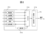
- FIG. 2 is a functional block diagram of the communication unit 171.
- the communication unit 171 includes a data buffer 1711, a selection unit 1712, a selector 1713, and a communication frame formation unit 1714.
- the data buffer 1711 receives the detection result of the angular velocity sensor 101 from the angular velocity characteristic correction unit 139, receives the detection result of the acceleration sensor in each axis direction from the X-axis direction acceleration characteristic correction unit 140 and the Y-axis direction acceleration characteristic correction unit 141, A temperature detection result is received from the temperature sensor 137.
- diagnosis results for each sensor are received from the diagnosis units 163 to 166.
- diagnosis results for the drive frequency and drive amplitude are received from the diagnosis units 161-162.
- the selection unit 1712 selects which of the detection results and diagnosis results held in the data buffer 1711 is to be transmitted to the external device as a transmission packet.
- the selection unit 1712 outputs the selection result to the selector 1713.
- the selector 1713 selects all or a part of each detection result and diagnosis result based on an instruction from the selection unit 1712 and outputs it to the communication frame forming unit 1714.
- the communication frame forming unit 1714 shapes all or part of each detection result and diagnosis result selected by the selector 1713 into a communication packet format, and transmits the communication packet to the external device.
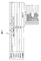
- FIG. 3 is a diagram showing a format of data held in the data buffer 1711. Hereinafter, the format of each data shown in FIG. 3 will be described.
- the angular velocity sensor 101, acceleration sensor, and temperature sensor 137 output detection results as 16-bit data.
- This detection result represents, for example, plus and minus signed values in two's complement. Depending on the required accuracy, the number of bits may be increased or decreased, and the detection result may be expressed in another expression format.
- Diagnostic information indicating the diagnostic result of each diagnostic unit is configured as 8-bit data. Each bit indicates a diagnosis result for the following items by 0 (normal) or 1 (abnormal).
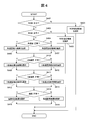
- FIG. 4 is a diagram illustrating an operation flow of the selection unit 1712. Hereinafter, each step of FIG. 4 will be described.
- Step S401 The selection unit 1712 determines whether the ROM 202 is operating normally based on the bit b4 of the diagnostic information held in the data buffer 1711. If it is operating normally, the process proceeds to step S402, and if it is abnormal, the process proceeds to step S403.
- Step S402 The selection unit 1712 determines whether or not the RAM 203 is operating normally based on the bit b3 of the diagnostic information held in the data buffer 1711. If it is operating normally, the process proceeds to step S404, and if it is abnormal, the process proceeds to step S405.
- Step S403 The selection unit 1712 notifies the selector 1713 that the diagnosis result (bit b4) in the ROM 202 has been selected.
- Step S404 The selection unit 1712 determines whether or not the angular velocity detection function of the angular velocity sensor 101 is operating normally based on the bits b5 to b7 of the diagnostic information held in the data buffer 1711. If it is operating normally, the process proceeds to step S406, and if it is abnormal, the process proceeds to step S407.
- Step S405 The selection unit 1712 notifies the selector 1713 that the diagnosis result (bit b3) in the RAM 203 has been selected.
- Step S406 The selection unit 1712 notifies the selector 1713 that the detection result of the angular velocity sensor 101 has been selected.
- Step S407 The selection unit 1712 notifies the selector 1713 that the diagnosis result (bits b5 to b7) of the angular velocity sensor 101 has been selected.
- Step S408 The selection unit 1712 determines whether or not the X-axis direction acceleration detection function of the acceleration sensor is operating normally, based on the bit b2 of the diagnostic information held in the data buffer 1711. If it is operating normally, the process proceeds to step S409, and if it is abnormal, the process proceeds to step S410.
- the selection unit 1712 notifies the selector 1713 that the detection result of the acceleration in the X-axis direction of the acceleration sensor has been selected.
- Step S410 The selection unit 1712 notifies the selector 1713 that the diagnosis result (bit b2) of the X-axis direction acceleration detection function of the acceleration sensor has been selected.
- Step S411 The selection unit 1712 determines whether or not the Y-axis direction acceleration detection function of the acceleration sensor is operating normally, based on the bit b1 of the diagnostic information stored in the data buffer 1711. If it is operating normally, the process proceeds to step S412, and if it is abnormal, the process proceeds to step S413.
- Step S412 The selection unit 1712 notifies the selector 1713 that the detection result of the acceleration in the Y-axis direction of the acceleration sensor has been selected.
- Step S413 The selection unit 1712 notifies the selector 1713 that the diagnosis result (bit b1) of the Y-axis direction acceleration detection function of the acceleration sensor has been selected.
- Step S4114 The selection unit 1712 determines whether or not the temperature detection function of the temperature sensor 137 is operating normally based on the bit b0 of the diagnostic information held in the data buffer 1711. If it is operating normally, the process proceeds to step S415, and if it is abnormal, the process proceeds to step S416.
- Step S4105 The selection unit 1712 notifies the selector 1713 that the detection result of the temperature sensor 137 has been selected.
- Step S416 The selection unit 1712 notifies the selector 1713 that the diagnosis result (bit b0) of the temperature detection function of the temperature sensor 137 has been selected.
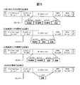
- FIG. 5 is a diagram illustrating a configuration example of a communication frame output from the communication frame forming unit 1714 as a result of the operation flow of FIG.
- a communication frame is configured in a CAN (Controller Area Network) frame format is shown.
- CAN Controller Area Network
- the CAN communication frame has an SOF (start of field), a control field, a data field, a CRC field, an ACK field, and an EOF (end of field) in one frame.
- the control field holds a value (DLC: Data Length Code) indicating the length of the data field.
- DLC Data Length Code
- the selection unit 1712 selects the detection result of each sensor and does not select the diagnosis result.
- the communication frame forming unit 1714 stores the detection result of each sensor in the communication frame, but does not store the diagnosis result.
- the selection unit 1712 does not select the detection result of the acceleration sensor. Instead, the diagnosis result of each sensor is selected.
- the communication frame forming unit 1714 stores the detection result of the angular velocity sensor, the detection result of the temperature sensor, and the diagnosis result of each sensor in the communication frame.
- the selection unit 1712 does not select the detection result of the angular velocity sensor 101. Instead, the diagnosis result of each sensor is selected.
- the selection unit 1712 does not select the detection result of each sensor. Instead, the diagnosis result of each sensor is selected. As a result, the communication frame forming unit 1714 stores the diagnosis result of each sensor in the communication frame. In this case, the length of the data field is 1 byte. The same applies when the ROM 202 is abnormal.
- the length of the data field is uniquely determined when all the sensors are normal and when the ROM 202 or RAM 203 is abnormal. Therefore, in these cases, the external device that receives the communication frame shown in FIG. 5 can determine which value is stored in the data field by only checking the DLC value.
- the physical quantity detection device 1000 transmits the detection result of the sensor when the sensor is operating normally, and displays the detection result of the sensor when the sensor is not operating normally. Send diagnostic results without sending. As a result, only information that needs to be notified to the external device can be transmitted, so that the communication load can be reduced. In addition, since the external device receives only the information that needs to be notified, the processing load at the time of reception can be reduced.
- the selection unit 1712 selects only information that needs to be notified to the external apparatus using the processing flow described in FIG. While this has the significance of reducing the communication load on the network and the processing load on the receiving side, it also has the significance of keeping the amount of information included in the data field within a predetermined limit.
- the maximum size of the data field is 8 bytes shown in FIG. 5 (1). Therefore, it is possible to transmit the detection results or diagnosis results of all sensors with only one communication frame. it can.
- the selection unit 1712 performs transmission so as to be within the maximum amount of information that can be included in one frame or one packet that is permitted in the communication frame format, communication packet format, and the like adopted by the communication unit 171. Information to be selected can be selected.
- the selection unit 1712 selects the minimum amount of information to be transmitted, if the amount of information cannot be accommodated in one frame or one packet, sensor detection is performed according to the accuracy of the requested sensor detection result.
- the lower bits of the result may be compressed.
- the detection result of each sensor is expressed by 16 bits.
- the lower 8 bits are required.
- the amount of information for 32 bits can be reduced. Therefore, even when a frame format or the like having a maximum information amount of 4 bytes that can be stored in the data field is used, all detections are performed by one transmission. Results or diagnostic results can be sent. Even when there are 5 to 8 sensors, the detection results of all the sensors can be transmitted by one transmission by compressing the information amount as described above.
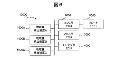
- FIG. 6 is a configuration diagram of a network system 10000 according to the third embodiment of the present invention.
- the network system 10000 is an in-vehicle network configured in a vehicle, and includes physical quantity detection devices 1000A, 1000B and 1000C, ESC (Electronic Stability Control) ECU (Engine Control Unit) 2000, ABS (anti-lock braking).
- ESC Electrical Stability Control
- ECU Engine Control Unit 2000
- ABS anti-lock braking
- the physical quantity detection device 1000A is a detection device that detects angular velocity and acceleration.
- the physical quantity detection device 1000B is a detection device that detects the speed of a traveling vehicle.
- the physical quantity detection device 1000 ⁇ / b> C is a detection device that detects a steering wheel angle of a running car.
- These detection apparatuses have the same configuration as the physical quantity detection apparatus 1000 described in the first and second embodiments, but the physical quantities to be detected and the sensors used to detect the physical quantities are different.
- the configuration for selecting information to be transmitted to the external device is the same as in the first and second embodiments.
- the physical quantity detection devices 1000A to 1000C are generically handled, they are referred to as the physical quantity detection device 1000.
- the ECU 2000 for ESC is an ECU that controls the vehicle to prevent a skid.
- the ABS ECU 3000 is an ECU that performs control to prevent slipping when sudden braking is applied during traveling.
- the airbag ECU 4000 is an ECU that controls the start of the airbag at the time of a vehicle collision.
- the brake unit 5000 individually controls the front, rear, left and right four-wheel brakes using hydraulic pressure in accordance with instructions from the ESC ECU 2000.
- Each of the detection devices 1000A to 1000C shown in FIG. 6 transmits the detection result of the sensor to each ECU via the in-vehicle network.
- Each ECU executes each control function using the detection result of the sensor.
- the “reception device” in the third embodiment corresponds to each ECU.
- the in-vehicle network and the in-vehicle control device (ECU) are exemplified as the components of the network system 10000.
- other network configurations may be employed.
- FIG. 7 is a functional block diagram of the ECU 2000 for ESC.
- the ESC ECU 2000 includes a reception unit 2001, a calculation unit 2002, and a brake control unit 2003.
- the receiving unit 2001 receives the detection results of each sensor from the physical quantity detection devices 1000A to 1000C.
- the calculation unit 2002 executes a processing flow described later with reference to FIG. 8 and extracts detection results of the sensors.
- the brake control unit 2003 outputs an operation instruction to the brake unit 5000 based on the detection result of each sensor extracted by the calculation unit 2002.
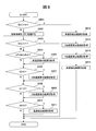
- FIG. 8 is an operation flow when the ESC ECU 2000 receives a communication frame from the physical quantity detection device 1000. Similar processing can be executed for ECUs other than the ESC ECU 2000. Hereinafter, each step of FIG. 8 will be described.
- the log recording destination may be a storage device such as a memory or a hard disk device provided in the ESC ECU 2000, for example.
- Arithmetic unit 2002 calculates the sum of bits b5 to b7 in the diagnostic information held in the data field of the communication frame. If the sum is 0, all of these bits are 0. Therefore, it is determined that the angular velocity sensor 101 is operating normally, and the process proceeds to step S805. Otherwise, skip to step S806.
- the calculating part 2002 acquires the detection result of the angular velocity sensor 101 from the data field of a communication frame.
- the obtained detection result is recorded in a storage device such as a memory or a hard disk device provided in the ESC ECU 2000, for example. The same applies when the detection result of each sensor is acquired in the following steps.
- the calculation unit 2002 acquires the acceleration detection result of the acceleration sensor in the X-axis direction from the data field of the communication frame.
- the calculation unit 2002 acquires the acceleration detection result of the acceleration sensor in the Y-axis direction from the data field of the communication frame.
- the calculating part 2002 acquires the detection result of the temperature sensor 137 from the data field of a communication frame.
- Steps S812 to S815) The calculation unit 2002 performs the same processing as steps S805, S807, S809, and S811.
- each ECU determines which sensor detection result is included in the data field based on the values of the bits b0 to b7 included in the diagnosis information.
- the process of acquiring detection results that are not included is omitted. Thereby, since the detection result of each sensor can be acquired only with the minimum necessary reception processing, the processing load of each ECU can be reduced.
- Embodiment 4 of the present invention a configuration for sharing the processing of the communication unit 171 for each physical quantity detection device 1000 will be described. Since other configurations are the same as those in the first to third embodiments, the configuration for sharing the processing of the communication unit 171 will be mainly described below.
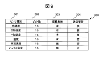
- FIG. 9 is a diagram illustrating a configuration of the definition table 300 held in the ROM 202 of the physical quantity detection device 1000 and an example of data.
- the definition table 300 is a table that defines from which sensor the physical quantity detection apparatus 1000 should acquire the detection result and transmit it to the external apparatus.
- the sensor type field 301, the bit number field 302, and the mounting presence / absence field 303 are defined.
- a transmission necessity field 304 is provided.
- the sensor type field 301 is a field for enumerating sensor types that may be mounted on the physical quantity detection device 1000.
- the bit number field 302 holds a value indicating the number of bits necessary to represent the detection result of the sensor identified by the value of the sensor type field 301.
- the mounting presence / absence field 303 holds a value indicating whether or not the physical quantity detection device 1000 is mounting the sensor identified by the value of the sensor type field 301.
- the transmission necessity field 304 holds a value indicating whether or not the detection result of the sensor identified by the value of the sensor type field 301 needs to be transmitted to the external device.
- the data example shown in FIG. 9 is a data example of the definition table 300 corresponding to the physical quantity detection device 1000 described in the first and second embodiments and the physical quantity detection device 1000A described in the third embodiment.
- the physical quantity detection devices 1000 and 1000A should acquire and transmit the detection result of the angular velocity sensor, the detection result of the acceleration sensor, and the detection result of the temperature sensor.
- the selection unit 1712 reads the definition table 300, grasps from which sensor the data stored in the data buffer 1711 is a detection result, selects only the detection result to be transmitted, and selects the selector 1713. Notify
- the processing contents to be performed by the communication unit 171 can be defined. Therefore, it is not necessary to individually develop the communication unit 171 for each sensor type included in each physical quantity detection device 1000. Only the data 300 need be adjusted. Thereby, the development burden of the physical quantity detection apparatus 1000 can be reduced. For example, if the record for the vehicle speed sensor in the definition table 300 is validated, the process to be performed by the communication unit 171 of the physical quantity detection device 1000B described in the third embodiment can be defined.
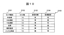
- FIG. 10 is a diagram showing a configuration and data example of the definition table 2100 held by each ECU. Although an example of the definition table 2100 held by the ESC ECU 2000 is shown here, other ECUs can hold the same definition table.
- the definition table 2100 is a table that defines which sensor the ESC ECU 2000 should process the detection result, and plays a role similar to that of the definition table 300 on the ESC ECU 2000 side.
- the definition table 2100 includes a sensor type field 2101, a bit number field 2102, a reception presence / absence field 2103, and a processing necessity field 2104.
- Sensor type field 2101 is a field that lists sensor types that may be received by ESC ECU 2000.
- the bit number field 2102 holds a value indicating the number of bits representing the detection result of the sensor identified by the value of the sensor type field 2101.
- the reception presence / absence field 2103 indicates whether or not the ESC ECU 2000 receives the detection result of the sensor identified by the value of the sensor type field 2101, that is, the detection result is transmitted from the physical quantity detection device 1000 to the ESC ECU 2000. Holds a value indicating whether to come or not.
- the processing necessity field 2104 holds a value indicating whether or not the ESC ECU 2000 needs to process the detection result of the sensor identified by the value of the sensor type field 2101.
- the processing contents of the calculation unit 2002 are changed, it is possible to define the processing contents to be executed by the calculation unit 2002 of the ESC ECU 2000. Therefore, the processing contents of the calculation unit 2002 are determined for each sensor type in which each ECU processes the detection result. There is no need for individual development, and only the definition data 2100 needs to be adjusted. Thereby, the development burden of each ECU can be reduced.
- each of the above-described configurations, functions, processing units, etc. can be realized as hardware by designing all or a part thereof, for example, with an integrated circuit, or the processor executes a program for realizing each function. By doing so, it can also be realized as software.
- Information such as programs and tables for realizing each function can be stored in a storage device such as a memory or a hard disk, or a storage medium such as an IC card or a DVD.
- 101 angular velocity sensor, 102: vibrator, 103: fixed electrode, 104 and 105: electrode, 106 and 107: fixed electrode, 108 and 109: fixed electrode, 110: capacitance detector, 112: capacitance detector, 122: VCO , 123: clock generation unit, 128 and 129: vibrator, 131 to 133: electrode, 135 and 136: capacitance detector, 137: temperature sensor, 138: AD converter, 139: angular velocity characteristic correction unit, 140: X axis Direction acceleration characteristic correction unit, 141: Y-axis direction acceleration characteristic correction unit, 145 and 146: AD converter, 148 and 149: AD converter, 151: Drive frequency adjustment unit, 152: Drive amplitude adjustment unit, 153: Angular velocity detection , 161 to 166: diagnosis unit, 167: diagnosis voltage control unit, 171: communication unit, 1711: data buffer, 712: Selection unit, 1713: Selector, 1714: Communication frame forming unit, 200: Microcomputer,
Abstract
Description
図1は、本発明の実施形態1に係る物理量検出装置1000の制御回路図である。図1において、角速度センサ101は、角速度を検出するセンサであり、振動子102、固定電極103、電極104および105、固定電極106および107、固定電極108および109を備える。 <
FIG. 1 is a control circuit diagram of a physical
(ビットb6)角速度センサ101の駆動振幅(診断部162の診断結果)
(ビットb5)角速度センサ101の角速度検出機能(診断部163の診断結果)
(ビットb4)ROM202の診断結果(CPU201が診断する)
(ビットb3)RAM203の診断結果(CPU201が診断する)
(ビットb2)X(左右)軸方向の加速度検出機能(診断部164の診断結果)
(ビットb1)Y(前後)軸方向の加速度検出機能(診断部165の診断結果)
(ビットb0)温度センサ137の温度検出機能(診断部166の診断結果) (Bit b7) Driving frequency of the angular velocity sensor 101 (diagnosis result of the diagnosis unit 161)
(Bit b6) Driving amplitude of the angular velocity sensor 101 (diagnosis result of the diagnosis unit 162)
(Bit b5) Angular velocity detection function of the angular velocity sensor 101 (diagnosis result of the diagnosis unit 163)
(Bit b4)
(Bit b3) Diagnosis result of RAM 203 (
(Bit b2) Acceleration detection function in X (left and right) axial direction (diagnosis result of diagnosis unit 164)
(Bit b1) Acceleration detection function in the Y (front-rear) axis direction (diagnosis result of the diagnosis unit 165)
(Bit b0) Temperature detection function of the temperature sensor 137 (diagnosis result of the diagnosis unit 166)
選択部1712は、データバッファ1711が保持している診断情報のビットb4に基づき、ROM202が正常稼動しているか否かを判断する。正常稼動している場合はステップS402へ進み、異常である場合はステップS403へ進む。 (FIG. 4: Step S401)
The
選択部1712は、データバッファ1711が保持している診断情報のビットb3に基づき、RAM203が正常稼動しているか否かを判断する。正常稼動している場合はステップS404へ進み、異常である場合はステップS405へ進む。 (FIG. 4: Step S402)
The
選択部1712は、ROM202の診断結果(ビットb4)を選択した旨を、セレクタ1713に通知する。 (FIG. 4: Step S403)
The
選択部1712は、データバッファ1711が保持している診断情報のビットb5~b7に基づき、角速度センサ101の角速度検出機能が正常稼動しているか否かを判断する。正常稼動している場合はステップS406へ進み、異常である場合はステップS407へ進む。 (FIG. 4: Step S404)
The
選択部1712は、RAM203の診断結果(ビットb3)を選択した旨を、セレクタ1713に通知する。 (FIG. 4: Step S405)
The
選択部1712は、角速度センサ101の検出結果を選択した旨を、セレクタ1713に通知する。 (FIG. 4: Step S406)
The
選択部1712は、角速度センサ101の診断結果(ビットb5~b7)を選択した旨を、セレクタ1713に通知する。 (FIG. 4: Step S407)
The
選択部1712は、データバッファ1711が保持している診断情報のビットb2に基づき、加速度センサのX軸方向加速度検出機能が正常稼動しているか否かを判断する。正常稼動している場合はステップS409へ進み、異常である場合はステップS410へ進む。 (FIG. 4: Step S408)
The
選択部1712は、加速度センサのX軸方向加速度の検出結果を選択した旨を、セレクタ1713に通知する。 (FIG. 4: Step S409)
The
選択部1712は、加速度センサのX軸方向加速度検出機能の診断結果(ビットb2)を選択した旨を、セレクタ1713に通知する。 (FIG. 4: Step S410)
The
選択部1712は、データバッファ1711が保持している診断情報のビットb1に基づき、加速度センサのY軸方向加速度検出機能が正常稼動しているか否かを判断する。正常稼動している場合はステップS412へ進み、異常である場合はステップS413へ進む。 (FIG. 4: Step S411)
The
選択部1712は、加速度センサのY軸方向加速度の検出結果を選択した旨を、セレクタ1713に通知する。 (FIG. 4: Step S412)
The
選択部1712は、加速度センサのY軸方向加速度検出機能の診断結果(ビットb1)を選択した旨を、セレクタ1713に通知する。 (FIG. 4: Step S413)
The
選択部1712は、データバッファ1711が保持している診断情報のビットb0に基づき、温度センサ137の温度検出機能が正常稼動しているか否かを判断する。正常稼動している場合はステップS415へ進み、異常である場合はステップS416へ進む。 (FIG. 4: Step S414)
The
選択部1712は、温度センサ137の検出結果を選択した旨を、セレクタ1713に通知する。 (FIG. 4: Step S415)
The
選択部1712は、温度センサ137の温度検出機能の診断結果(ビットb0)を選択した旨を、セレクタ1713に通知する。 (FIG. 4: Step S416)
The
全てのセンサが正常稼動している場合、選択部1712は、各センサの検出結果を選択し、診断結果は選択しない。その結果、通信フレーム形成部1714は、通信フレーム内に各センサの検出結果を格納するが、診断結果は格納しない。この場合、データフィールドの長さは、2バイト×4=8バイトとなる。 (1) When all the sensors are normal When all the sensors are operating normally, the
加速度センサが異常である場合、選択部1712は、加速度センサの検出結果を選択しない。これに代えて、各センサの診断結果を選択する。その結果、通信フレーム形成部1714は、通信フレーム内に、角速度センサの検出結果、温度センサの検出結果、各センサの診断結果を格納する。この場合、データフィールドの長さは、2バイト×2+1バイト=5バイトとなる。 (2) When the acceleration sensor is abnormal When the acceleration sensor is abnormal, the
角速度センサ101が異常である場合、選択部1712は、角速度センサ101の検出結果を選択しない。これに代えて、各センサの診断結果を選択する。その結果、通信フレーム形成部1714は、通信フレーム内に、加速度センサの検出結果、温度センサ137の検出結果、各センサの診断結果を格納する。この場合、データフィールドの長さは、2バイト×3+1バイト=7バイトとなる。 (3) When the angular velocity sensor is abnormal When the
RAM203が異常である場合、選択部1712は、各センサの検出結果を選択しない。これに代えて、各センサの診断結果を選択する。その結果、通信フレーム形成部1714は、通信フレーム内に各センサの診断結果を格納する。この場合、データフィールドの長さは1バイトとなる。ROM202が異常である場合も同様である。 (4) When the RAM is abnormal When the
以上のように、本実施形態1に係る物理量検出装置1000は、センサが正常稼動している場合はそのセンサの検出結果を送信し、センサが正常稼動していない場合はそのセンサの検出結果を送信せずに診断結果を送信する。これにより、外部装置に通知する必要がある情報のみを送信することができるので、通信負荷を軽減することができる。また、外部装置は通知を受ける必要がある情報のみを受信するので、受信時における処理負荷も軽減することができる。 <Embodiment 1: Summary>
As described above, the physical
実施形態1において、選択部1712は、図4で説明した処理フローを用いて、外部装置に通知する必要がある情報のみを選択することとした。これは、ネットワークの通信負荷および受信側の処理負荷を軽減する意義がある一方で、データフィールド内に含める情報量を所定限度内に収める意義もある。 <Embodiment 2>
In the first embodiment, the
図6は、本発明の実施形態3に係るネットワークシステム10000の構成図である。ネットワークシステム10000は、車両内に構成された車載ネットワークであり、物理量検出装置1000A、1000Bおよび1000C、ESC(エレクトロニック・スタビリティ・コントロール)用ECU(Engine Control Unit)2000、ABS(アンチロック・ブレーキング・システム)用ECU3000、エアバッグ用ECU4000、ブレーキユニット5000を有する。 <
FIG. 6 is a configuration diagram of a
演算部2002は、物理量検出装置1000から受信した通信フレームのDLCの値を取得する。DLC=8であればステップS812へ進み、それ以外であればステップS802へ進む。 (FIG. 8: Step S801)
The
演算部2002は、DLC=8でない場合はいずれかのセンサについて異常が発生しているものと判断し、診断情報をログに記録する。ログの記録先は、例えばESC用ECU2000が備えるメモリやハードディスク装置などの記憶装置とすればよい。 (FIG. 8: Step S802)
If DLC = 8, the
演算部2002は、DLC=1であれば各センサの検出結果は物理量検出装置1000から受信した通信フレーム内に格納されていないと判断して本動作フローを終了し、それ以外であればステップS804へ進む。 (FIG. 8: Step S803)
The
演算部2002は、通信フレームのデータフィールドが保持している診断情報のうち、ビットb5~b7の総和を求める。総和が0であればこれらのビットが全て0であるので、角速度センサ101が正常稼動していると判断し、ステップS805へ進む。それ以外であればステップS806へスキップする。 (FIG. 8: Step S804)
演算部2002は、角速度センサ101の検出結果を、通信フレームのデータフィールドから取得する。取得した検出結果は、例えばESC用ECU2000が備えるメモリやハードディスク装置などの記憶装置に記録する。以下のステップにおいて各センサの検出結果を取得した場合も同様である。 (FIG. 8: Step S805)
The calculating
演算部2002は、通信フレームのデータフィールドが保持している診断情報のうち、ビットb2の値を取得する。b2=0であれば加速度センサのX軸方向加速度検出機能が正常稼動していると判断し、ステップS807へ進む。それ以外であればステップS808へスキップする。 (FIG. 8: Step S806)
The
演算部2002は、加速度センサのX軸方向の加速度検出結果を、通信フレームのデータフィールドから取得する。 (FIG. 8: Step S807)
The
演算部2002は、通信フレームのデータフィールドが保持している診断情報のうち、ビットb1の値を取得する。b1=0であれば加速度センサのY軸方向加速度検出機能が正常稼動していると判断し、ステップS809へ進む。それ以外であればステップS810へスキップする。 (FIG. 8: Step S808)
The
演算部2002は、加速度センサのY軸方向の加速度検出結果を、通信フレームのデータフィールドから取得する。 (FIG. 8: Step S809)
The
演算部2002は、通信フレームのデータフィールドが保持している診断情報のうち、ビットb0の値を取得する。b0=0であれば温度センサ137が正常稼動していると判断し、ステップS811へ進む。それ以外であれば本動作フローを終了する。 (FIG. 8: Step S810)
The
演算部2002は、温度センサ137の検出結果を、通信フレームのデータフィールドから取得する。 (FIG. 8: Step S811)
The calculating
演算部2002は、ステップS805、S807、S809、S811と同様の処理を実施する。 (FIG. 8: Steps S812 to S815)
The
以上のように、本実施形態3に係るネットワークシステム10000において、各ECUは、DLC=8でない場合、すなわち各センサの診断結果を受信した場合のみ、その診断結果をログに記録する。これにより、ログ記録処理に係る処理負荷を軽減することができる。 <Embodiment 3: Summary>
As described above, in the
実施形態1~3では、物理量検出装置1000が備えるセンサ種別はあらかじめ定まっていることを前提としたが、実施形態3で説明したようにセンサ種別のみが異なる物理量検出装置1000を複数用いる場合でも、通信部171が実施する処理は同様である。 <
In the first to third embodiments, it is assumed that the sensor type included in the physical
Claims (12)
- 物理量を検出するセンサと、
前記センサの稼動状態を診断する診断部と、
前記センサの検出結果および前記診断部の診断結果を送信する通信部と、
前記通信部が前記センサの検出結果および前記診断部の診断結果のうちいずれを送信するかを選択する選択部と、
を備え、
前記選択部は、
前記センサが正常に稼動していると前記診断部が診断した場合は前記センサの検出結果を選択し、
前記センサが正常に稼動していないと前記診断部が診断した場合は前記センサの検出結果を選択せずに前記診断部の診断結果を選択する
ことを特徴とする物理量検出装置。 A sensor for detecting a physical quantity;
A diagnostic unit for diagnosing the operating state of the sensor;
A communication unit that transmits a detection result of the sensor and a diagnosis result of the diagnosis unit;
A selection unit that selects which of the detection result of the sensor and the diagnosis result of the diagnosis unit is transmitted by the communication unit;
With
The selection unit includes:
If the diagnostic unit diagnoses that the sensor is operating normally, select the detection result of the sensor,
The physical quantity detection device, wherein when the diagnosis unit diagnoses that the sensor is not operating normally, the diagnosis result of the diagnosis unit is selected without selecting the detection result of the sensor. - 前記通信部は、
前記センサの検出結果または前記診断部の診断結果を1つの通信パケット内に含めることができない場合は、前記センサの検出結果を記述する情報を下位ビットから順に圧縮して情報量を削減する
ことを特徴とする請求項1記載の物理量検出装置。 The communication unit is
When the detection result of the sensor or the diagnosis result of the diagnosis unit cannot be included in one communication packet, information describing the detection result of the sensor is compressed in order from the lower bits to reduce the amount of information. The physical quantity detection device according to claim 1, wherein: - 前記通信部は、
前記センサの検出結果のみを送信するときはその旨を示す情報を併せて送信し、
前記センサの検出結果を送信しないときはその旨を示す情報を併せて送信する
ことを特徴とする請求項1記載の物理量検出装置。 The communication unit is
When sending only the detection result of the sensor, send information indicating that,
The physical quantity detection device according to claim 1, wherein when the detection result of the sensor is not transmitted, information indicating that is transmitted together. - 当該物理量検出装置が備える前記センサの種類を定義する定義テーブルを備え、
前記通信部は、
前記定義テーブルが定義している前記センサの検出結果およびそのセンサについての前記診断部の診断結果を送信する
ことを特徴とする請求項1記載の物理量検出装置。 A definition table for defining the type of the sensor included in the physical quantity detection device;
The communication unit is
The physical quantity detection device according to claim 1, wherein the detection result of the sensor defined by the definition table and the diagnosis result of the diagnosis unit for the sensor are transmitted. - 前記センサは、
互いに直交する第1方向および第2方向に変位可能な振動体を有し、
前記振動体を前記第1方向に振動させた状態において、角速度の発生により前記振動体が前記第2方向に変位したときの変位量を角速度として検出する
ことを特徴とする請求項1記載の物理量検出装置。 The sensor is
Having a vibrating body displaceable in a first direction and a second direction orthogonal to each other;
2. The physical quantity according to claim 1, wherein in a state in which the vibrating body is vibrated in the first direction, a displacement amount when the vibrating body is displaced in the second direction due to generation of an angular velocity is detected as an angular velocity. Detection device. - 前記センサは、
互いに直交する第1方向および第2方向に変位可能な振動体を有し、
前記振動体が前記第1方向および前記第2方向に変位したときの変位量を加速度として検出する
ことを特徴とする請求項1記載の物理量検出装置。 The sensor is
Having a vibrating body displaceable in a first direction and a second direction orthogonal to each other;
The physical quantity detection device according to claim 1, wherein a displacement amount when the vibrating body is displaced in the first direction and the second direction is detected as an acceleration. - 請求項1記載の物理量検出装置と、
前記物理量検出装置が送信する情報を受信する受信装置と、
を有することを特徴とするネットワークシステム。 The physical quantity detection device according to claim 1;
A receiving device that receives information transmitted by the physical quantity detection device;
A network system comprising: - 請求項3記載の物理量検出装置と、
前記物理量検出装置が送信する情報を受信する受信装置と、
を有し、
前記受信装置は、
前記物理量検出装置から前記診断部の診断結果を受信した場合のみ、その診断結果をログとして記録する
ことを特徴とするネットワークシステム。 The physical quantity detection device according to claim 3,
A receiving device that receives information transmitted by the physical quantity detection device;
Have
The receiving device is:
Only when the diagnosis result of the diagnosis unit is received from the physical quantity detection device, the diagnosis result is recorded as a log. - 前記受信装置は、
前記物理量検出装置から前記センサの検出結果のみを送信した旨の情報を受信したときは、前記センサが正常に稼動していると判断して前記センサの検出結果を全て記録し、前記診断部の診断結果を受信する処理を実施しない
ことを特徴とする請求項8記載のネットワークシステム。 The receiving device is:
When the information indicating that only the detection result of the sensor has been transmitted from the physical quantity detection device is received, it is determined that the sensor is operating normally, and all the detection results of the sensor are recorded. The network system according to claim 8, wherein the process of receiving the diagnosis result is not performed. - 前記受信装置は、
前記物理量検出装置から前記センサの検出結果を送信しない旨の情報を受信したときは、前記センサの検出結果を受信する処理を実施しない
ことを特徴とする請求項8記載のネットワークシステム。 The receiving device is:
The network system according to claim 8, wherein when receiving information indicating that the detection result of the sensor is not transmitted from the physical quantity detection device, the process of receiving the detection result of the sensor is not performed. - 前記受信装置は、
前記物理量検出装置から受信した前記診断部の診断結果が、前記センサが正常に稼動していない旨を示している場合は、前記物理量検出装置から受信した情報のなかに、当該センサの検出結果が含まれていないものとして取り扱う
ことを特徴とする請求項8記載のネットワークシステム。 The receiving device is:
When the diagnosis result of the diagnostic unit received from the physical quantity detection device indicates that the sensor is not operating normally, the detection result of the sensor is included in the information received from the physical quantity detection device. The network system according to claim 8, wherein the network system is handled as not included. - 請求項1記載の物理量検出装置と、
前記物理量検出装置が送信する情報を受信する受信装置と、
を有し、
前記受信装置は、
前記物理量検出装置から受信する前記センサの検出結果の種類を定義する定義テーブルを備え、
前記物理量検出装置から受信した情報を、前記定義テーブルが定義している前記センサの検出結果およびそのセンサについての前記診断部の診断結果として処理する
ことを特徴とするネットワークシステム。 The physical quantity detection device according to claim 1;
A receiving device that receives information transmitted by the physical quantity detection device;
Have
The receiving device is:
A definition table that defines the type of detection result of the sensor received from the physical quantity detection device;
The network system, wherein information received from the physical quantity detection device is processed as a detection result of the sensor defined by the definition table and a diagnosis result of the diagnosis unit for the sensor.
Priority Applications (2)
| Application Number | Priority Date | Filing Date | Title |
|---|---|---|---|
| DE112011103597T DE112011103597T5 (en) | 2010-10-28 | 2011-10-20 | Physical size and network system detection device |
| US13/879,566 US20130226506A1 (en) | 2010-10-28 | 2011-10-20 | Physical Quantity Detection Device, And Network System |
Applications Claiming Priority (2)
| Application Number | Priority Date | Filing Date | Title |
|---|---|---|---|
| JP2010-242351 | 2010-10-28 | ||
| JP2010242351A JP5554684B2 (en) | 2010-10-28 | 2010-10-28 | Physical quantity detection device, network system |
Publications (1)
| Publication Number | Publication Date |
|---|---|
| WO2012056980A1 true WO2012056980A1 (en) | 2012-05-03 |
Family
ID=45993693
Family Applications (1)
| Application Number | Title | Priority Date | Filing Date |
|---|---|---|---|
| PCT/JP2011/074106 WO2012056980A1 (en) | 2010-10-28 | 2011-10-20 | Physical quantity detection device and network system |
Country Status (4)
| Country | Link |
|---|---|
| US (1) | US20130226506A1 (en) |
| JP (1) | JP5554684B2 (en) |
| DE (1) | DE112011103597T5 (en) |
| WO (1) | WO2012056980A1 (en) |
Families Citing this family (3)
| Publication number | Priority date | Publication date | Assignee | Title |
|---|---|---|---|---|
| JP6084473B2 (en) * | 2013-02-01 | 2017-02-22 | 日立オートモティブシステムズ株式会社 | Compound sensor |
| US9668035B2 (en) * | 2014-04-18 | 2017-05-30 | Rosemount Aerospace, Inc. | Microelectromechanical rate sensor |
| JP6521236B2 (en) * | 2015-04-03 | 2019-05-29 | セイコーエプソン株式会社 | Physical quantity processing circuit, physical quantity processing device, electronic device and moving body |
Citations (4)
| Publication number | Priority date | Publication date | Assignee | Title |
|---|---|---|---|---|
| JP2000002542A (en) * | 1998-06-15 | 2000-01-07 | Matsushita Electric Ind Co Ltd | Angular velocity sensor |
| JP2001165951A (en) * | 1999-12-07 | 2001-06-22 | Denso Corp | Detected signal processor for rotary sensor and output method for detecting signal of the rotary sensor |
| JP4311496B1 (en) * | 2008-04-04 | 2009-08-12 | パナソニック株式会社 | Inertial sensor |
| JP2010107331A (en) * | 2008-10-30 | 2010-05-13 | Denso Corp | Device and system for detecting physical quantity |
Family Cites Families (2)
| Publication number | Priority date | Publication date | Assignee | Title |
|---|---|---|---|---|
| JP3322067B2 (en) * | 1995-04-24 | 2002-09-09 | 株式会社デンソー | Physical quantity detector |
| US8793085B2 (en) * | 2011-08-19 | 2014-07-29 | Allegro Microsystems, Llc | Circuits and methods for automatically adjusting a magnetic field sensor in accordance with a speed of rotation sensed by the magnetic field sensor |
-
2010
- 2010-10-28 JP JP2010242351A patent/JP5554684B2/en not_active Expired - Fee Related
-
2011
- 2011-10-20 DE DE112011103597T patent/DE112011103597T5/en not_active Withdrawn
- 2011-10-20 US US13/879,566 patent/US20130226506A1/en not_active Abandoned
- 2011-10-20 WO PCT/JP2011/074106 patent/WO2012056980A1/en active Application Filing
Patent Citations (4)
| Publication number | Priority date | Publication date | Assignee | Title |
|---|---|---|---|---|
| JP2000002542A (en) * | 1998-06-15 | 2000-01-07 | Matsushita Electric Ind Co Ltd | Angular velocity sensor |
| JP2001165951A (en) * | 1999-12-07 | 2001-06-22 | Denso Corp | Detected signal processor for rotary sensor and output method for detecting signal of the rotary sensor |
| JP4311496B1 (en) * | 2008-04-04 | 2009-08-12 | パナソニック株式会社 | Inertial sensor |
| JP2010107331A (en) * | 2008-10-30 | 2010-05-13 | Denso Corp | Device and system for detecting physical quantity |
Also Published As
| Publication number | Publication date |
|---|---|
| JP5554684B2 (en) | 2014-07-23 |
| JP2012093301A (en) | 2012-05-17 |
| US20130226506A1 (en) | 2013-08-29 |
| DE112011103597T5 (en) | 2013-09-05 |
Similar Documents
| Publication | Publication Date | Title |
|---|---|---|
| EP2088043A1 (en) | Fail safe test for motion sensors | |
| US7284408B2 (en) | Sensor system | |
| CN101443628B (en) | Moving body with tilt angle estimating mechanism | |
| JP3991978B2 (en) | Vehicle angular velocity sensor correction diagnosis device | |
| JP6429993B2 (en) | Improved resolution of the rotational speed signal between multiple rotational speed pulses | |
| EP2177918B1 (en) | Sensor apparatus with failure diagnosis | |
| JP5844178B2 (en) | In-vehicle device | |
| WO2014119143A1 (en) | Inertial force detection device | |
| EP2369295A2 (en) | Apparatus for detecting angular velocity and acceleration | |
| JP2005283481A (en) | Sensor system | |
| JP5554684B2 (en) | Physical quantity detection device, network system | |
| JP2004294335A (en) | Vehicle control system using abnormality detection method, and program and device for oscillation type angular velocity sensor | |
| JP2011064515A (en) | Angular speed and acceleration detector | |
| WO2013002085A1 (en) | Angular velocity detection device | |
| JP4327720B2 (en) | Sensor, controller and method for monitoring at least one sensor | |
| GB2368400A (en) | Acceleration sensor fault detector | |
| WO2013111454A1 (en) | Physical quantity-detecting device | |
| CN111527002A (en) | Torque modulation to linearize tire slip characteristics | |
| JP4543869B2 (en) | Sensor circuit in vibration type angular velocity sensor | |
| US10677610B2 (en) | Circuit device, physical quantity detection device, electronic apparatus, and vehicle | |
| JP5249001B2 (en) | Physical quantity sensor and control device for physical quantity sensor | |
| KR20160061814A (en) | Inertial sensor module | |
| KR100629798B1 (en) | Integrated control apparatus for chassis | |
| JP5982222B2 (en) | Acceleration detector | |
| JP2003525814A (en) | System and device for detecting yawing motion with redundant measurement channels |
Legal Events
| Date | Code | Title | Description |
|---|---|---|---|
| 121 | Ep: the epo has been informed by wipo that ep was designated in this application |
Ref document number: 11836116 Country of ref document: EP Kind code of ref document: A1 |
|
| WWE | Wipo information: entry into national phase |
Ref document number: 1120111035977 Country of ref document: DE Ref document number: 112011103597 Country of ref document: DE |
|
| WWE | Wipo information: entry into national phase |
Ref document number: 13879566 Country of ref document: US |
|
| 122 | Ep: pct application non-entry in european phase |
Ref document number: 11836116 Country of ref document: EP Kind code of ref document: A1 |