WO2012053716A1 - 알에프아이디 태그가 설치된 병마개 및 찢어지는 라벨 태그 - Google Patents
알에프아이디 태그가 설치된 병마개 및 찢어지는 라벨 태그 Download PDFInfo
- Publication number
- WO2012053716A1 WO2012053716A1 PCT/KR2011/003701 KR2011003701W WO2012053716A1 WO 2012053716 A1 WO2012053716 A1 WO 2012053716A1 KR 2011003701 W KR2011003701 W KR 2011003701W WO 2012053716 A1 WO2012053716 A1 WO 2012053716A1
- Authority
- WO
- WIPO (PCT)
- Prior art keywords
- bottle
- rfid
- screw
- cap
- tag
- Prior art date
- Legal status (The legal status is an assumption and is not a legal conclusion. Google has not performed a legal analysis and makes no representation as to the accuracy of the status listed.)
- Ceased
Links
Images

Classifications
-
- G—PHYSICS
- G09—EDUCATION; CRYPTOGRAPHY; DISPLAY; ADVERTISING; SEALS
- G09F—DISPLAYING; ADVERTISING; SIGNS; LABELS OR NAME-PLATES; SEALS
- G09F3/00—Labels, tag tickets, or similar identification or indication means; Seals; Postage or like stamps
- G09F3/02—Forms or constructions
- G09F3/03—Forms or constructions of security seals
- G09F3/0305—Forms or constructions of security seals characterised by the type of seal used
- G09F3/0329—Forms or constructions of security seals characterised by the type of seal used having electronic sealing means
- G09F3/0335—Forms or constructions of security seals characterised by the type of seal used having electronic sealing means using RFID tags
-
- G—PHYSICS
- G06—COMPUTING OR CALCULATING; COUNTING
- G06K—GRAPHICAL DATA READING; PRESENTATION OF DATA; RECORD CARRIERS; HANDLING RECORD CARRIERS
- G06K19/00—Record carriers for use with machines and with at least a part designed to carry digital markings
- G06K19/04—Record carriers for use with machines and with at least a part designed to carry digital markings characterised by the shape
-
- G—PHYSICS
- G06—COMPUTING OR CALCULATING; COUNTING
- G06K—GRAPHICAL DATA READING; PRESENTATION OF DATA; RECORD CARRIERS; HANDLING RECORD CARRIERS
- G06K19/00—Record carriers for use with machines and with at least a part designed to carry digital markings
- G06K19/06—Record carriers for use with machines and with at least a part designed to carry digital markings characterised by the kind of the digital marking, e.g. shape, nature, code
- G06K19/067—Record carriers with conductive marks, printed circuits or semiconductor circuit elements, e.g. credit or identity cards also with resonating or responding marks without active components
- G06K19/07—Record carriers with conductive marks, printed circuits or semiconductor circuit elements, e.g. credit or identity cards also with resonating or responding marks without active components with integrated circuit chips
- G06K19/077—Constructional details, e.g. mounting of circuits in the carrier
- G06K19/0772—Physical layout of the record carrier
- G06K19/07726—Physical layout of the record carrier the record comprising means for indicating first use, e.g. a frangible layer
-
- G—PHYSICS
- G09—EDUCATION; CRYPTOGRAPHY; DISPLAY; ADVERTISING; SEALS
- G09F—DISPLAYING; ADVERTISING; SIGNS; LABELS OR NAME-PLATES; SEALS
- G09F3/00—Labels, tag tickets, or similar identification or indication means; Seals; Postage or like stamps
- G09F3/08—Fastening or securing by means not forming part of the material of the label itself
- G09F3/10—Fastening or securing by means not forming part of the material of the label itself by an adhesive layer
-
- G—PHYSICS
- G09—EDUCATION; CRYPTOGRAPHY; DISPLAY; ADVERTISING; SEALS
- G09F—DISPLAYING; ADVERTISING; SIGNS; LABELS OR NAME-PLATES; SEALS
- G09F3/00—Labels, tag tickets, or similar identification or indication means; Seals; Postage or like stamps
- G09F3/02—Forms or constructions
- G09F2003/0222—Features for removal or adhesion, e.g. tabs
-
- G—PHYSICS
- G09—EDUCATION; CRYPTOGRAPHY; DISPLAY; ADVERTISING; SEALS
- G09F—DISPLAYING; ADVERTISING; SIGNS; LABELS OR NAME-PLATES; SEALS
- G09F3/00—Labels, tag tickets, or similar identification or indication means; Seals; Postage or like stamps
- G09F3/02—Forms or constructions
- G09F2003/023—Adhesive
- G09F2003/0239—Permanent adhesive
-
- G—PHYSICS
- G09—EDUCATION; CRYPTOGRAPHY; DISPLAY; ADVERTISING; SEALS
- G09F—DISPLAYING; ADVERTISING; SIGNS; LABELS OR NAME-PLATES; SEALS
- G09F3/00—Labels, tag tickets, or similar identification or indication means; Seals; Postage or like stamps
- G09F3/02—Forms or constructions
- G09F2003/0272—Labels for containers
- G09F2003/0273—Labels for bottles, flasks
Definitions
- the present invention relates to a bottle cap and a tear label tag installed with the RFID tag, more specifically, the RFID tag is installed on the bottle cap to provide identification information on the authenticity of the product when unopened, and is destroyed after opening
- the cover sheet which is made of a bottle cap and the surface of which the brand name is printed on the surface and the label tag coated with the antenna printing pattern including the RFID IC chip on the back of the cover sheet are integrally bonded by the adhesive layer.
- a perforated line is formed to be easily torn during use, and a label tag is attached to a portion where the lid and the lid are opened and closed in a screw-coupled form, such as expensive liquor bottles, so that the quantity of sales of liquor bottles can be easily calculated and inventory management.
- torn label tags that can be used for theft protection.
- the RFID tag for authenticity identification is attached to the injection preventing device or label to prevent the injection of fake alcoholic beverages again after opening.
- the RFID tag is provided with a label embedded therein.
- a number of systems such as Korean Patent Application Publication No. 2005-89724, are disclosed as a system capable of determining the authenticity of alcoholic products by attaching an RFID tag to a label or the like, and to be used in such a system as shown in FIG.
- the RFID tag 40 consisting of the RFID chip 410 and the antenna 420 is attached to the label 5 surrounding the bottle cap 4 of the bottle cap 4 to provide identification information on the authenticity of the product. After that, the antenna is damaged and is no longer available for use is disclosed in Republic of Korea Patent Publication No. 20006-113018, Republic of Korea Patent No. 692119, Republic of Korea Utility Model No. 252202.
- the label is thin so that it is easy to reveal whether the RFID tag is attached.Also, labels made mainly of synthetic resin can be removed without damaging the RFID tag, and the Internet can be used. There was a problem that it is possible to illegally reuse only the RFID tag that did not verify the authenticity through.
- the conventional label tag has to coat the copper printed pattern of the copper (Cu) material including the RFID IC chip by a separate process on the back of the cover paper, which is a soft asterisk film material, so that the manufacturing process is complicated and mass production is difficult. Since it is not easy, there is a problem that the product price according to the rise, and also because the label tag is not made in the form of a sticker, there is a problem that can not be attached to the bent portion, such as opening and closing the bottle and lid in the form of screw coupling.
- Cu copper
- the present invention has been proposed to solve the above problems of the prior art, the object of the present invention can not easily recognize the existence of the RFID tag, when opening the bottle cap is unconditionally broken and illegal reuse is not possible RFID tag In addition to providing a bottle cap provided with, while providing an RFID tag that can not be re-injected additionally.
- another object of the present invention is to integrally adhere the cover sheet, which is a paper material printed on the surface of the trade name and the like, and a label tag coated with an antenna printing pattern including an RFID IC chip on the back of the cover sheet by an adhesive layer.
- a perforated line is formed to be easily torn during use, and a label tag is attached to a portion where the lid and the lid are opened and closed in the form of screwing, such as expensive liquor bottles, to facilitate the sales quantity calculation and inventory management of the liquor bottles.
- it provides a torn label tag that can be used for anti-theft protection.
- the bottle cap provided with the RFID tag according to the present invention has a fluid through hole for outflowing fluid from the inside of the bottle to the outside, and has a first screw part installed at the center, and an encapsulation part fixedly installed at the bottle inlet; ;
- a stopper portion comprising a first rotational power transmission unit provided at the upper lower surface, a third screw unit formed at the inner circumferential surface of the side wall, and a thin film unit installed at the upper center portion;
- a second screw portion coupled to the first screw portion of the encapsulation portion, a second torque force transmission portion installed on an outer surface to receive a rotational force from the first rotation force transmission portion, and to rotate the second screw portion, and the first and second power transfer portions;
- a movable part having a pressing protrusion for moving the second screw part upward while rotating along the first screw part and finally damaging the thin film part in accordance with rotation;
- the third screw portion of the cap is combined with the fourth screw portion of the outer peripheral surface of the inlet of the bottle or the outer peripheral surface of the sealing portion is made to seal or open the bottle by the cap,
- the pitch of the first and second screw portions is longer than the pitch of the third and fourth screw portions to rotate the stopper to open the bottle for the first time so that the pressurizing protrusion of the movable portion rises before the stopper is separated from the bottle opening to break the thin film portion. It is characterized by.
- the bottle cap provided with the RFID tag according to the present invention is a fluid through hole for outflowing the fluid from the inside of the bottle, and the rotational prevention portion provided in the center, the sealing portion is fixed to the bottle inlet;
- a movable part including an anti-rotation coupling part inserted into the lower part of the anti-rotation part to prevent rotation thereof, and a first screw part installed at a central portion thereof toward an upper side thereof;
- a stopper portion comprising a first rotational power transmission unit provided at the upper lower surface, a third screw unit formed at the inner circumferential surface of the side wall, and a thin film unit installed at the upper center portion;
- a second screw portion engaged with the first screw portion of the driven portion, a second torque force portion installed on an outer surface to receive a rotational force from the first torque transmission portion, and to rotate the second screw portion, and the first and second rotational powers;
- a movable part having a pressurizing protrusion for moving the second screw part upward while rotating along the first screw part and finally damaging the
- the third screw portion of the cap is coupled to the fourth screw portion on the outer circumferential surface of the inlet of the bottle or the outer circumferential surface of the encapsulation portion so as to seal or open the bottle by the cap.
- the pitch of the first and second screw portions is longer than the pitch of the third and fourth screw portions to rotate the stopper to open the bottle for the first time so that the pressurizing protrusion of the movable portion rises before the stopper is separated from the bottle opening to break the thin film portion. It is characterized by.
- the RFID may form a space in which the RFID chip may be damaged or the RFID chip may be disconnected from the antenna according to a displacement generated by the pressing protrusion of the movable part moving upward, to damage the thin film portion of the plug portion. It is also preferable to further secure the receiving portion in cooperation with the closure portion, the closure portion is installed on the top of the closure portion and RF ID portion.
- the tearing label tag according to the present invention is a cover sheet made of paper and a label tag coated with an antenna printing pattern including an RFID IC chip on the back of the cover sheet by integrally adhesively formed by an adhesive layer for a bottle and a lid It is characterized in that it is used to attach to the opening and closing portion in the form of screwing.
- the central portion of the cover sheet is characterized in that to form a tear line so as to tear easily during use.
- the surface of the cover sheet is characterized by displaying a brand name printed.
- the label tag is formed in an H shape.
- the RFID reader When received by the RFID reader through the antenna provided in the RFID reader, the RFID reader is characterized in that it transmits the various related information of the contents of the bottle bottle sent from the label tag structure to the computer via a wireless LAN (LAN).
- LAN wireless LAN
- the bottle cap provided with the RFID tag according to the present invention can not easily determine whether the RFID tag is attached. Also, when the bottle cap is opened, the RFID ID part is broken and illegal reuse is impossible and the fluid cannot be re-injected. It is effective.
- the tearing label tag according to the present invention is a cover sheet made of a paper material printed on the surface and the label, and a label tag coated with an antenna printing pattern including an RFID IC chip on the back of the cover sheet by an adhesive layer
- a label tag to the opening and closing of the bottle and the lid of the expensive bottle such as expensive bottle and calculate the sales quantity of the bottle and inventory management
- 1 is a view showing a conventional injection preventing device.
- FIG. 2 is a view showing a form wrapped around a label with a conventional RFID tag.
- Figure 3 and Figure 4 is a view for explaining the first embodiment of the bottle cap is installed RF ID tag according to the present invention.
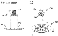
- 5 and 6 are views for explaining the second embodiment of the bottle cap is installed RF ID tag according to the present invention.
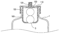
- FIG. 7 is a view showing an embodiment in which the injection preventing device of the present invention is installed.
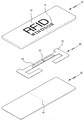
- FIG. 8 is an overall exploded perspective view of a torn label tag in accordance with the present invention.
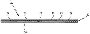
- Figure 9 is an enlarged cross-sectional view of the bonding state of the torn label tag in accordance with the present invention.
- FIG. 10 is a perspective view of a finished product of a torn label tag according to the present invention.
- 11 is an exemplary state of use of the torn label tag according to the present invention.
- FIG. 12 is a block diagram of an information recognition device of a torn label tag according to the present invention.
- Figure 3a and Figure 3b is an exploded cross-sectional view and exploded perspective view showing a bottle cap of Example 1 according to the present invention.
- the bottle cap according to the first embodiment includes an encapsulation part 100 fixedly installed at the inlet of the bottle 1, a cap part 300 capable of opening or sealing the bottle inlet, and moving upwards according to the rotation of the cap part. It is largely composed of a pressing part 200 formed with pressing protrusions to damage the thin film part provided at the center, an RFID tag 400 attached to an upper surface of the plug part, and a finishing part 500 covering the plug part and the RFID tag. Are distinguished.
- the encapsulation part 100 is provided with a fluid through hole 110 for outflowing the fluid from the inside of the bottle to the outside, and the center of the first screw part 120 is provided.
- the stopper 300 has a third screw portion 310 on the inner circumferential surface of the side wall like a normal bottle cap, and the first lower power transmission portion 320 is provided on the upper lower surface thereof, and the center of the upper portion is a thin film portion. It consists of 330.
- the third screw portion 310 of the plug portion 300 is coupled to the fourth screw portion 130 of the outer peripheral surface of the inlet 10 of the bottle 10 as shown in FIG. 3, or the fourth screw portion 130 formed on the outer surface of the encapsulation portion 100 as shown in FIG. 4. It may be combined with the screw 130.
- the RFID tag 400 is attached to the top surface of the stopper 300.
- the RFID tag 400 includes an RFID chip 410 and an antenna 420.
- the first rotational force transmission unit 320 is illustrated as having a hexagonal partition wall, and the second rotational force transmission unit 210 of the hexagon will be described later, but such first and second rotational forces are provided.
- the transmission unit 320 or 210 is not limited to a hexagon, and may have any shape such that the rotation of the stopper may be transmitted to the second rotation power transmission unit through the first rotation power transmission unit.
- the movable part 200 of FIG. 3B is provided with a second rotational power transmission unit 210 having an outer circumferential surface of a hexagon, and as described above, the second rotational power transmission unit 210 is coupled to the first rotational power transmission unit 320. do.
- the upper surface of the movable part 200 is provided with a pressing protrusion 220, the movable part 200 is rotated through the first and second power transmission parts 320 and 210 in accordance with the rotation of the stopper 300, the encapsulation part ( The movable part 200 is raised along the first rotational force transmitting part 320 by the second threaded part 230 of the movable part 200 coupled to the first threaded part 120 of 100.
- the pressing protrusion 220 comes into contact with the thin film part 330 of the stopper part 300, and the third screw part 310 of the stopper part 300 and the fourth feeding part or the enclosing part of the plug part 300. Before the screw 130 is separated from each other, the pressing protrusion 220 penetrates the thin film portion 330 of the plug portion 300 and comes out to the top surface of the plug portion 300.
- the thread pitch of the first and second threaded parts 120 and 230 may be longer than the thread pitch of the third and fourth threaded parts 310 and 130.
- the pressing protrusion 220 that penetrates the thin film portion 330 on the top surface of the stopper 300 may push or damage the RF ID chip 410 attached to the thin film portion or push the RF ID chip 410 to antenna 420. It should be disconnected from the, but the pressure protrusion is required as much space as the displacement above the stopper to push the RF chip 410 as described above.
- the purpose of the RFID tag is not easily recognized, it is also preferable to use a finish 500 covering the top of the plug and the RFID tag.
- a finish 500 covering the top of the plug and the RFID tag.
- the antenna may also be installed by insert injection molding when manufacturing the plug, and may be installed in the form of printing using a metal paste on the top of the plug, and recognize the existence by attaching the antenna so as to be properly placed in the uneven pattern. It would be possible to make it impossible.
- the second embodiment is provided with a rotation preventing portion 140 in place of the first screw portion in the encapsulation portion 100 as shown in Figs.
- the movable part 250 having the rotation preventing coupling part 150 and the first screw part 120 fitted to the rotation preventing part 140 is provided.
- the anti-rotation part 140 includes a protrusion 141
- the anti-rotation coupling part 150 includes a concave groove 151 corresponding to the protrusion 141, and is inserted into the encapsulation part 100.
- the movable part 250 does not rotate.
- the movable part 250 is inserted below the encapsulation part 100, but as shown in FIG. 6, the movable part 250 may be inserted above the encapsulation part 100.
- the first and second power transmission units have a hexagonal shape for transmitting rotational force
- the anti-rotation coupling unit and the anti-rotation unit are described as protrusions and concave grooves, but any shape for transmitting rotational force or preventing rotation is possible.
- any shape for transmitting rotational force or preventing rotation is possible.
- Example 2 In addition, the rest of the working relationship of Example 2 is the same as in Example 1.
- the encapsulation portion 100 is first inserted into the bottle inlet, and then the movable portion 200 is attached to the first screw portion 120 of the encapsulation portion 100. Insert the first and second threads 120 and 230 to be completely fastened, and the plug ID 300 having the RFID tag 300 and the finishing part 500 is inserted into the bottle inlet. At this time, the stopper 300 should not allow the third screw part 310 to be processed so that the stopper part 300 may enter the end of the fourth screw part 130.
- the plug portion 330 may be formed to correspond to the fourth screw portion by heat-sealing the outer circumferential surface of the position where the third screw portion is to be processed.
- the stopper part 300 and the encapsulation part 100 provided with the RF ID tag 300 and the finishing part 500 are removed. It is coupled through the 3,4 threaded portion (310,130).
- N the number of revolutions to be rotated in order to fully fasten the movable part 200 spanning the first screw part 120
- the number of revolutions at which the third and fourth screw parts 310 and 130 are completely fastened is N
- the first and second rotational power transmission parts are designed by adjusting dimensions and the like so as not to be coupled with each other. If the stopper is rotated by N-n times and the first and second turn power transfer parts are coupled to each other, the first and second screw parts and the third and fourth screw parts may rotate n times to achieve complete fastening.
- the bottle cap of the present invention can be installed at the bottle inlet by inserting the sealing part into the bottle inlet.
- the coupling method according to the first, second, third, fourth, screw parts and the first and second rotational force transmitting parts may be used even when the fourth screw part is formed at the bottle inlet of FIG. 3.
- FIG. 8 is an exploded perspective view of a torn label tag in accordance with the present invention
- FIG. 9 is an enlarged cross-sectional view of a bonded state of the torn label tag in accordance with the present invention
- FIG. It is a perspective view of the finished product.
- the label tag structure 9 of the present invention has a label tag 20 coated with an antenna printing pattern 22 including an RFID IC chip 21 on a rear surface thereof, and an adhesive layer 30.
- the cover sheet 10 is integrally bonded by the.
- the cutting line 40 in the center portion of the cover sheet 10 to facilitate cutting.
- Reference numeral 23 in FIG. 8 denotes a space formed in the antenna print pattern 22.
- the effect of product advertisement may be enhanced by printing various brand names 11 and the like on the surface of the cover sheet 10 formed of paper and serving as a cover.
- the label tag 20 coated with the antenna printing pattern 22 including the RFID IC chip 21 is attached to the cover sheet 10 integrally by the adhesive layer 30 on the rear surface of the cover sheet 10.
- the antenna printing pattern 22 of the label tag 20 is formed in a substantially H shape in order to improve reception sensitivity in consideration of the area of the cover sheet 10.
- a cut line 40 overlapping each other is formed, and as shown in FIG. 4, the bottle 1 and the lid 51 are opened and closed in the form of screwing ( 52, the perforation line 40 is attached so that the label tag structure 9 is more easily torn when the lid 51 is opened.
- FIG. 12 is a block diagram of an information recognition device of a torn label tag according to the present invention.
- the bottle 52 and the lid 51 are opened and closed in a screw-joined form.
- the RFID reader 70 When received by the RFID reader 70 through the antenna 60 provided in the external RFID reader 70 via the RFID reader 70, various kinds of contents of the bottle 1 sent from the label tag structure 9 in the RFID reader 70
- the relevant information is transmitted to the computer 80 via a wireless LAN, and accordingly, the computer 80 compares the previously stored database with the sales quantity of the liquor bottle needed for the contents of the liquor bottle 1.
- Output devices such as monitoring various related information services such as calculation, inventory management and anti-theft Which it will be provided through.
Landscapes
- Engineering & Computer Science (AREA)
- Physics & Mathematics (AREA)
- General Physics & Mathematics (AREA)
- Theoretical Computer Science (AREA)
- Computer Security & Cryptography (AREA)
- Computer Hardware Design (AREA)
- Microelectronics & Electronic Packaging (AREA)
- Details Of Rigid Or Semi-Rigid Containers (AREA)
- Closures For Containers (AREA)
Abstract
본 발명은 알에프아이디 태그가 병마개에 설치되어 미개봉시에는 상품의 진위 여부에 대한 식별정보를 제공하며, 개봉 후에는 파괴되어 더 이상 사용이 불가능하도록 한 병마개에 관한 것이다. 병마개는 병 입구에 고정 설치되는 봉입부와, 병 입구를 개봉하거나 밀봉할 수 있는 마개부와, 상기 마개부의 회전에 따라 상측으로 이동하며 마개부의 중심에 구비된 박막부를 파손하도록 가압돌기가 형성된 가압부와, 상기 마개부의 박막부 상면에 부착되는 알에프아이디 태그로 크게 구분되는 알에프아이디 태그가 설치된 병마개에 관한 것이다. 또한, 본 발명은 표면에 상품명 등이 인쇄된 종이재질인 커버시트와, 상기 커버시트의 배면에 RFID IC칩을 포함하는 안테나 인쇄패턴이 코팅된 라벨태그를 접착층에 의해 일체로 접착하고, 상기 커버시트의 중앙부에는 사용시 쉽게 찢어지도록 절취선을 형성하여 고가인 양주병 등의 병과 뚜껑이 나사결합 형태로 개폐되는 부위에 라벨 태그를 부착하여 양주병의 판매수량 산출 및 재고관리를 용이하게 할 뿐만 아니라, 도난방지용으로도 사용할 수 있도록 한 찢어지는 라벨 태그에 관한 것이다.
Description
본 발명은 알에프아이디 태그가 설치된 병마개 및 찢어지는 라벨 태그에 관한 것으로, 보다 상세하게는 알에프아이디 태그가 병마개에 설치되어 미개봉시에는 상품의 진위 여부에 대한 식별정보를 제공하며, 개봉 후에는 파괴되어 더 이상 사용이 불가능하도록 한 병마개 및 표면에 상품명 등이 인쇄된 종이재질인 커버시트와, 상기 커버시트의 배면에 RFID IC칩을 포함하는 안테나 인쇄패턴이 코팅된 라벨태그를 접착층에 의해 일체로 접착하고, 상기 커버시트의 중앙부에는 사용시 쉽게 찢어지도록 절취선을 형성하여 고가인 양주병 등의 병과 뚜껑이 나사결합 형태로 개폐되는 부위에 라벨 태그를 부착하여 양주병의 판매수량 산출 및 재고관리를 용이하게 할 뿐만 아니라, 도난방지용으로도 사용할 수 있도록 한 찢어지는 라벨 태그에 관한 것이다.
최근 고가 주류상품을 위조한 가짜 주류상품이 유통되고 있으며, 이러한 가짜 주류상품을 방지하기 위하여, 개봉 후 다시 가짜 주류를 주입할 수 없도록 하기 위한 주입방지 장치 또는 레이블에 정품 식별용 알에프아이디 태그를 부착하여 개봉시 레이블이 찢어져 알에프아이디 태그가 손상되도록 하는 알에프아이디 태그가 내장된 레이블 등이 제공되고 있다.
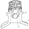
주입방지장치로는 도 1과 대한민국 등록특허 제772499호를 들 수 있는데, 용기(1)의 밸브 하우징(2)에 2개의 볼(3)을 주입하고, 이러한 2개의 볼(3)와 밸브 하우징(2)의 상호작용에 의해 용기(1) 내에서 외부로 액체를 분출시킬 수는 있어도 다시 용기(1) 내에 액체를 재충전할 수 없도록 한 구조가 개시되어 있다.
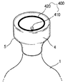
또한, 레이블 등에 알에프아이디 태그를 부착하여 주류상품의 진위를 파악할 수 있는 시스템으로는 대한민국 공개특허 2005-89724호와 같은 것이 다수 공개되어 있으며, 이러한 시스템에 사용되기 위해 도 2와 같이 용기(1)의 병마개(4)를 감싸는 레이블(5)에 알에프아이디 칩(410)과 안테나(420)으로 이루어진 알에프아이디 태그(40)를 부착하여 미개봉시에는 상품의 진위 여부에 대한 식별정보를 제공하며, 개봉 후에는 안테나가 파손되어 더 이상 사용이 불가능하도록 한 것이 대한민국 공개특허 20006-113018호, 대한민국 등록특허 692119호, 대한민국 등록실용신안 252202호등에 개시되어 있다.
그러나 알에프아이디 태그를 레이블 등에 부착한 경우에는 레이블의 두께가 얇아 알에프아이디 태그의 부착 여부가 드러나기 쉽고, 또한 합성수지재로 주로 제작되는 레이블은 알에프아이디 태그의 손상없이 뜯어내는 것이 가능할 뿐만 아니라 인터넷 등을 통해 진품확인을 하지 않은 알에프아이디 태그만을 수집하여 불법적으로 재사용하는 것이 가능한 문제점이 있었다.
또한, 종래의 라벨 태그는 연질의 아스테지필름 재질인 커버지의 배면에 별도의 공정에 의해 RFID IC칩을 포함하는 동(Cu) 재질의 안테나 인쇄패턴을 코팅해야만 하므로 제조공정이 복잡하여 다량생산이 용이하지 못하므로 그에 따른 제품단가가 상승되는 문제점이 있고, 또한 라벨 태그가 스티커 형태로 제작된 것이 아니므로 병과 뚜껑이 나사결합 형태로 개폐되는 굴곡진 부위 등에는 부착 사용이 불가능한 문제점이 있었다.
따라서, 본 발명은 상기한 종래 기술의 문제점을 해결하고자 제안된 것으로서, 본 발명의 목적은 알에프아이디 태그의 존재를 쉽게 인식할 수 없으며, 병마개를 개봉하면 무조건 파손되어 불법적인 재사용이 불가능한 알에프아이디 태그를 설치한 병마개를 제공하는 한편, 부가적으로 유체의 재주입이 불가능하도록 하는 알에프아이디 태그를 제공함에 있다.
또한, 본 발명의 다른 목적은 표면에 상품명 등이 인쇄된 종이재질인 커버시트와, 상기 커버시트의 배면에 RFID IC칩을 포함하는 안테나 인쇄패턴이 코팅된 라벨태그를 접착층에 의해 일체로 접착하고, 상기 커버시트의 중앙부에는 사용시 쉽게 찢어지도록 절취선을 형성하여 고가인 양주병 등의 병과 뚜껑이 나사결합 형태로 개폐되는 부위에 라벨 태그를 부착하여 양주병의 판매수량 산출 및 재고관리를 용이하게 할 뿐만 아니라, 도난방지용으로도 사용할 수 있도록 한 찢어지는 라벨 태그를 제공함에 있다.
상기한 목적을 달성하기 위하여 본 발명에 따른 알에프아이디 태그가 설치된 병마개는 병 내부로부터 유체를 외부로 유출시키는 유체통과공과, 중심에 설치된 제 1 나사부를 구비하며, 병 입구에 고정 설치되는 봉입부와; 상부 하면에 설치되는 제1회전력 전달부와, 측벽 내주면에 형성된 제 3 나사부와, 상부 중심부에 설치되는 박막부로 이루어진 마개부와; 상기 봉입부의 제 1 나사부와 결합하는 제 2 나사부와, 외면에 설치되어 상기 제 1 회전력전달부로 부터 회전력을 전달받아 제 2 나사부를 회전시키는 제 2 회전력전달부와, 상기 제1,2회전력전달부의 회전에 따라 상기 제 2 나사부가 상기 제 1 나사부를 따라 회전하면서 상측으로 이동되며 최종적으로 상기 박막부를 파손하는 가압돌기를 구비한 가동부와; 상기 마개부 상면의 박막부 위에 부착되는 알에프아이디 칩과, 상기 마개부 상면에 설치되며 상기 알에프아이디 칩과 연결되는 안테나로 이루어진 알에프아이디 태그로 이루어지며;
상기 마개부의 제3 나사부는 병의 입구 외주면 또는 상기 봉입부의 외주면의 제 4 나사부와 결합하여 상기 마개부에 의해 병을 밀봉 또는 개봉할 수 있도록 이루어지며,
상기 제1,2나사부의 피치는 제3,4나사부의 피치보다 길어서 마개부를 회전시켜 병을 최초로 개방함에 있어 마개부가 병입구로부터 분리되기 이전에 가동부의 가압돌기가 상승하여 상기 박막부를 파손하도록 하는 것을 특징으로 한다.
또한, 본 발명에 따른 알에프아이디 태그가 설치된 병마개는 병 내부로부터 유체를 외부로 유출시키는 유체통과공과, 중심부에 회전방지부를 구비하며, 병 입구에 고정 설치되는 봉입부와; 상기 회전방지부의 하측으로 삽입되어 회전이 방지되도록 하는 회전방지 결합부와, 상측을 향해 중심부에 설치된 제 1 나사부로 이루어진 피가동부와; 상부 하면에 설치되는 제1회전력 전달부와, 측벽 내주면에 형성된 제 3 나사부와, 상부 중심부에 설치되는 박막부로 이루어진 마개부와; 상기 피가동부의 제 1 나사부와 결합하는 제 2 나사부와, 외면에 설치되어 상기 제 1 회전력전달부로 부터 회전력을 전달받아 제 2 나사부를 회전시키는 제 2 회전력전달부와, 상기 제1,2회전력전달부의 회전에 따라 상기 제 2 나사부가 상기 제 1 나사부를 따라 회전하면서 상측으로 이동되며 최종적으로 상기 박막부를 파손하는 가압돌기를 구비한 가동부와; 상기 마개부 상면의 박막부 위에 부착되는 알에프아이디 칩과, 상기 마개부 상면에 설치되며 상기 알에프아이디 칩과 연결되는 안테나로 이루어진 알에프아이디 태그로 이루어지며;
상기 마개부의 제3 나사부는 병의 입구 외주면 또는 상기 봉입부의 외주면에 제 4 나사부와 결합하여 상기 마개부에 의해 병을 밀봉 또는 개봉할 수 있도록 이루어지며,
상기 제1,2나사부의 피치는 제3,4나사부의 피치보다 길어서 마개부를 회전시켜 병을 최초로 개방함에 있어 마개부가 병입구로부터 분리되기 이전에 가동부의 가압돌기가 상승하여 상기 박막부를 파손하도록 하는 것을 특징으로 한다.
또한, 상기 상측으로 이동되는 가동부의 가압돌기가 상기 마개부의 박막부를 파손시키기 위해 발생하는 변위에 따라 상기 알에프아이디 칩이 파손되거나 상기 알에프아이디 칩과 안테나의 연결이 끊어질 수 있는 공간을 이루는 알에프아이디 수용부를 상기 마개부와 협력하여 확보하며, 상기 마개부 및 알에프아이디부의 상측에 설치되는 마감부를 더 포함하는 것도 바람직하다.
또한, 본 발명에 따른 찢어지는 라벨 태그는 종이재질인 커버시트와, 상기 커버시트의 배면에 RFID IC칩을 포함하는 안테나 인쇄패턴이 코팅된 라벨태그를 접착층에 의해 일체로 접착 형성하여 양주병과 뚜껑이 나사결합 형태로 개폐되는 부위에 부착하여 사용함을 특징으로 한다.
상기 커버시트의 중앙부에는 사용시 쉽게 찢어지도록 절취선을 형성함을 특징으로 한다.
상기 커버시트의 표면에는 상품명을 인쇄하여 표출함을 특징으로 한다.
상기 라벨태그는 H자 형상으로 형성됨을 특징으로 한다.
상기 양주병과 뚜껑이 나사결합 형태로 개폐되는 부위에 부착 사용되는 라벨태그 구조의 배면에 구비된 RFID IC 칩에 저장된 양주병 내용물의 인식 관련 정보가 RFID IC 칩과 함께 형성된 안테나 인쇄패턴을 거쳐 외부의 RFID 리더에 구비된 안테나를 통해 RFID 리더에 수신되면, RFID 리더에서는 라벨태그 구조로부터 전송된 양주병 내용물의 각종 관련 정보들을 무선랜(LAN)을 통해 컴퓨터로 전송하는 것을 특징으로 한다.
상기 양주병 내용물의 각종 관련 정보들은 상기 컴퓨터에 미리 저장된 데이터 베이스와 비교하여 양주병 내용물에 필요한 양주병의 판매수량 산출, 재고관리 및 도난방지 등 각종 관련 정보서비스를 모니터 등의 출력장치를 통해 제공하는 것을 특징으로 한다.
이와 같이 이루어진 본 발명에 따른 알에프아이디 태그가 설치된 병마개는 알에프아이디 태그의 부착여부를 쉽게 파악할 수 없으며, 또한 병마개를 개봉하면 알에프아이디부가 파손되어 불법적인 재사용이 불가능하며, 유체의 재주입이 불가능하도록 하는 효과가 있다.
또한, 본 발명에 따른 찢어지는 라벨 태그는 표면에 상품명 등이 인쇄된 종이재질인 커버시트와, 상기 커버시트의 배면에 RFID IC칩을 포함하는 안테나 인쇄패턴이 코팅된 라벨태그를 접착층에 의해 일체로 접착하고, 상기 커버시트의 중앙부에는 사용시 쉽게 찢어지도록 절취선을 형성하여 고가인 양주병 등의 병과 뚜껑이 나사결합 형태로 개폐되는 부위에 라벨 태그를 부착하여 양주병의 판매수량 산출 및 재고관리를 용이하게 할 뿐만 아니라, 도난방지용으로도 사용할 수 있는 효과가 있다.
도 1은 종래의 주입방지장치를 나타낸 도면.
도 2는 종래의 RFID 태그가 부착된 레이블을 감싼 형태를 나타낸 도면.
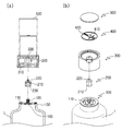
도 3 및 도 4는 본 발명에 따른 알에프아이디 태그가 설치된 병마개의 실시예 1을 설명하기 위한 도면.
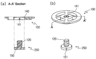
도 5 및 도 6은 본 발명에 따른 알에프아이디 태그가 설치된 병마개의 실시예 2를 설명하기 위한 도면.
도 7은 본 발명의 주입방지장치가 설치된 실시예를 나타낸 도면.
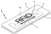
도 8은 본 발명에 따른 찢어지는 라벨 태그의 전체 분해 사시도.
도 9는 본 발명에 따른 찢어지는 라벨 태그의 결합상태의 확대 단면도.
도 10은 본 발명에 따른 찢어지는 라벨 태그의 완성품의 사시도.
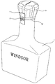
도 11은 본 발명에 따른 찢어지는 라벨 태그의 사용 상태예시도.
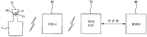
도 12는 본 발명에 따른 찢어지는 라벨 태그의 정보인식 장치의 블록 구성도이다.
이하, 본 발명을 그 실시예에 따라 도면을 참조하여 보다 상세하게 설명한다.
도 3a 및 도 3b는 본 발명에 따른 실시예 1의 병마개를 도시한 분해단면도 및 분해사시도이다.
실시예 1의 병마개는 병(1) 입구에 고정 설치되는 봉입부(100)와, 병 입구를 개봉하거나 밀봉할 수 있는 마개부(300)와, 상기 마개부의 회전에 따라 상측으로 이동하며 마개부의 중심에 구비된 박막부를 파손하도록 가압돌기가 형성된 가압부(200)와, 상기 마개부의 상면에 부착되는 알에프아이디 태그(400)와, 상기 마개부와 알에프아이디태그를 덮는 마감부(500)로 크게 구분된다.
먼저 봉입부(100)는 병 내부로부터 유체를 외부로 유출시키는 유체통과공(110)을 구비하고 있으며, 그 중심에는 제 1 나사부(120)가 구비되어 있다.
또한 마개부(300)는 통상의 병마개와 같이 측벽 내주면에 제3나사부(310)를 구비하고 있으며, 그 상부 하면에는 제1회전력 전달부(320)가 구비되어 있고, 또한 상부의 중심은 박막부(330)로 이루어져 있다.
마개부(300)의 제3나사부(310)는 도 3과 같이 병(10)입구 외주면의 제4나사부(130)와 결합되거나, 또는 도 4와 같이 봉입부(100)의 외면에 형성된 제 4 나사부(130)와 결합될 수도 있다.
마개부(300)의 상면에는 알에프아이디 태그(400)이 부착되게 된다. 알에프아이디 태그(400)는 알에프아이디 칩(410)과 안테나(420)로 이루어진다.
본 실시예에서는 제1 회전력 전달부(320)는 육각형의 격벽을 구비한 것으로 도시되어 있고, 이후 설명될 육각형의 제2회전력 전달부(210)를 끼워 넣도록 되어 있으나, 이러한 제1, 2 회전력 전달부(320,210)는 육각형으로 한정될 이유는 없으며 돌기부 등을 구비하여 마개부의 회전이 제1회전력 전달부를 통해 제2회전력전달부로 전달될 수 있는 어떠한 형태라도 가능하다.
도 3b의 가동부(200)는 외주면이 육각형으로 이루어진 제2회전력 전달부(210)가 구비되어 있고, 상기 설명한 바와 같이 제2회전력 전달부(210)는 제1회전력전달부(320)와 결합되게 된다. 가동부(200)의 상면에는 가압돌기(220)가 구비되어 있으며, 마개부(300)의 회전에 따라 제1,2회전력 전달부(320,210)을 통해 가동부(200)가 회전하게 되며, 봉입부(100)의 제 1 나사부(120)과 결합된 가동부(200)의 제 2 나사부(230)에 의해 가동부(200)는 제 1 회전력 전달부(320)를 따라 상승하게 된다.
가동부(200)의 상승에 따라 가압돌기(220)는 상기 마개부(300)의 박막부(330)에 닿게 되며, 마개부(300)의 제3나사부(310) 및 병입구 또는 봉입부의 제4나사부(130)가 서로 분리되기 이전에 가압돌기(220)은 상기 마개부(300)의 박막부(330)를 뚫고 마개부(300)의 상면으로 나오게 된다.
이를 위하여는 제3,4나사부(310,130)의 나사 피치보다 제 1, 2 나사부(120, 230)의 나사 피치가 더 길도록 설계하면 된다.
마개부(300) 상면의 박막부(330)를 뚫고 나온 가압돌기(220)은 박막부에 부착된 알에프아이디 칩(410)을 밀어 파손시키거나 또는 알에프아이디 칩(410)을 밀어서 안테나(420)과의 연결이 끊어지도록 해야하는데, 가압돌기가 알에프아이디 칩(410)을 상기와 같이 밀기 위해서는 마개부 상측으로 그 변위만큼의 공간이 필요하게 된다.
본 발명에서는 알에프아이디 태그가 쉽게 인식되지 않도록 하는 것을 그 목적으로 하는 바, 마개부의 상면과 알에프아이디 태그를 덮는 마감부(500)를 사용하는 것도 바람직하다. 본 실시예에서는 마개부(300)의 상면의 테두리에 단턱을 형성해 마감부(500)를 끼움으로써 이러한 공간을 확보하였으나, 마개부의 하면 테두리에 단턱을 설치해 마개부와 결합시키는 것도 가능할 것이다.
마감부 없이도 알에프아이디 태그의 존재를 쉽게 인식할 수 없도록 할 수도 있는데, 이때는 안테나를 마개부의 상면에 설치하되 적어도 알에프아이디 칩과 연결되는 안테나의 단자부는 마개부 상면에 노출되도록 하여 단자부와 알에프아이디 칩을 연결하는 것도 가능할 것이다. 통상 주류의 병마개 상면에는 상표와 같은 정보를 요철문양으로 형성하기 때문에 알에프아이디 칩 역시 이러한 요철문양 속에 같이 부착되도록 하여 그 존재를 인식할 수 없도록 하는 것이다. 안테나의 경우도 마개부 제작시 인서트 사출성형을 통해 설치할 수도 있을 것이며, 마개부 상면에 금속페이스트를 사용하여 인쇄하는 형태로 설치될 수 있고, 요철 문양속에 적절히 배치되도록 안테나를 부착하여 그 존재를 인식할 수 없도록 하는 것도 가능할 것이다.
상기 실시예 1에서는 봉입부에 제 1 나사부가 가공된 것을 설명하였으나, 실시예 2에서는 도 5 및 도 6과 같이 봉입부(100)에 제 1 나사부 대신 회전방지부(140)를 구비하고, 이러한 회전방지부(140)에 끼워지는 회전방지 결합부(150)와 제1나사부(120)를 구비한 피가동부(250)가 구비되게 된다.
도 5에서 회전방지부(140)는 돌기부(141)를, 회전방지 결합부(150)는 상기 돌기부(141)에 대응하는 오목홈(151)을 구비하고 있어, 봉입부(100)에 끼워진 피가동부(250)은 회전하지 않게 된다.
도 5에서는 봉입부(100)의 하방으로 피가동부(250)가 삽입되는 형태를 도시하였으나, 도 6과 같이 봉입부(100)의 상방으로 피가동부(250)가 삽입되는 것도 가능할 것이다.
상기 실시예에서는 제1,2회전력 전달부는 회전력을 전달하기 위해 육각형 형상으로, 회전방지 결합부와 회전방지부는 돌기와 오목홈으로 설명하였지만, 상호간에 회전력을 전달하거나 회전방지를 위한 어떠한 형상도 가능함은 물론이다.
그외, 실시예 2의 나머지 작용관계는 실시예 1과 동일하다.
또한 도 7과 같이 봉입부(100)의 하단으로 관로를 이루는 벽체(160)를 형성하고, 이러한 벽체(160)가 이룬 관로를 통한 병내 유체만이 유체통과공을 통과하여 외부로 유출될 수 있도록 하고, 이러한 벽체가 이룬 관로상에 볼을 유지시켜, 병을 기울이지 않으면 상기 볼이 벽체의 바닥면의 통공을 막도록 하는 것도 바람직하다.
이에 따라 가입돌기의 상승에 의해서도 알에프아이디 태그가 불능화되지 않는 경우가 발생하더라도, 병 내부로 가짜 주류를 주입할 수 없도록 하는 것이 가능해진다.
이하, 이러한 병 마개를 병에다 설치하는 방법에 대해 설명한다.
실시예 1의 도 3과 같이 병 입구 외주면에 제4나사부가 가공된 경우에는 봉입부(100)를 먼저 병 입구에 끼운 다음, 봉입부(100)의 제 1 나사부(120)에 가동부(200)를 끼워 제 1,2 나사부(120,230)가 완전히 체결되도록 하고, 알에프아이디태그(300)와 마감부(500)가 설치된 마개부(300)를 병 입구에 끼우게 된다. 이때 마개부(300)에는 제3나사부(310)가 가공되어 있지않아 제4나사부(130)의 끝까지 마개부(300)가 진입할 수 있도록 하여야 한다. 끼워진 마개부(330)는 제3나사부를 가공할 위치의 외주면을 가열융착함에 따라 제3나사부가 제4나사부와 대응되게 형성될 수 있다.
또한 실시예 1의 도 4에 도시한 바와 같이, 봉입부(100)의 외주면에 제4나사부(130)가 가공된 경우에는 다음과 같이 병마개가 결합될 수도 있다.
봉입부(100)의 제 1 나사부(120)에 가동부(200)을 약간 걸쳐 놓은 다음, 알에프아이디태그(300)와 마감부(500)이 설치된 마개부(300)와 봉입부(100)를 제3,4 나사부(310,130)를 통해 결합시킨다. 제1나사부(120)에 걸쳐진 가동부(200)가 완전히 체결되기 위해 회전하여야 하는 회전수를 n이라 하고, 제3,4나사부(310,130)이 완전히 체결되는 회전수를 N이라 하였을 때, 마개부와 봉입부의 결합을 위해 마개부가 회전하는 회전수가 N-n 만큼 되기 전에는 제1,2회전력 전달부가 서로 결합되지 않도록 치수 등을 조절하여 설계한다. N-n 횟수만큼 마개부가 회전하여 제1,2회전력 전달부가 서로 결합을 이루면 제1,2나사부와 제3,4나사부는 n 횟수만큼 회전하면서 완전한 체결을 이루도록 할 수 있을 것이다.
이에 따라 봉입부(100)와 마개부(200)를 완전히 체결한 후, 봉입부를 병 입구에 끼워 설치함에 따라 본 발명의 병마개를 병 입구에 설치가능하게 되는 것이다.
또한 상기 제1,2,3,4,나사부 및 제 1,2 회전력 전달부에 따른 결합방법은 도 3의 병 입구에 제4나사부가 형성된 경우에도 사용할 수 있음은 물론이다.
또한, 도8은 본 발명에 따른 찢어지는 라벨 태그의 전체 분해 사시도이고, 도9는 본 발명에 따른 찢어지는 라벨 태그의 결합상태의 확대 단면도이며, 도10은 본 발명에 따른 찢어지는 라벨 태그의 완성품의 사시도이다.
도8 내지 도10에 도시된 바와 같이 본 발명의 라벨 태그 구조(9)는 배면에 RFID IC칩(21)을 포함하는 안테나 인쇄패턴(22)이 코팅된 라벨태그(20)가 접착층(30)에 의해 일체로 접착된 커버시트(10)로 구성된다.
종이 재질인 커버 시트(10)의 표면에는 각종 상품명(11)등을 인쇄하여 표출되도록 구성된다.
또한, 상기 커버 시트(10)의 중앙부에는 절단이 용이하도록 절취선(40)을 형성하는 것이 바람직하다.
도8 중 미설명 부호 23은 안테나 인쇄패턴(22)에 형성된 공간부이다.
이와 같이 구성된 본 발명에 따른 찢어지는 라벨 태그의 동작을 첨부된 도11 및 도12를 참조하여 상세히 설명하면 다음과 같다.
먼저, 도8 및 도9에 도시한 바와 같이 종이재질로 형성되어 커버지 역할을 하는 커버 시트(10)의 표면에는 각종 상품명(11) 등을 인쇄하여 표출되도록 함으로서 제품광고 효과를 높일 수 있다.
커버 시트(10)의 배면에는 RFID IC칩(21)을 포함하는 안테나 인쇄패턴(22)이 코팅된 라벨태그(20)가 접착층(30)에 의해 일체로 커버 시트(10)에 접착된다.
이 경우 라벨태그(20)의 안테나 인쇄패턴(22)은 커버 시트(10)의 면적을 고려하여 수신감도를 보다 좋게 하기 위하여 대략 H자 형상으로 형성한다.
커버 시트(10)와 박막의 접착층(30)의 중앙부에는 상호 겹치는 절취선(40)을 형성하고 도4에 도시한 바와 같이 양주병(1)과 뚜껑(51)이 나사결합 형태로 개폐되는 부위(52)에 절취선(40)이 일치하도록 부착하여 뚜껑(51)을 열 때에 라벨 태그 구조(9)가 보다 쉽게 찢어지도록 한 것이다.
도12는 본 발명에 따른 찢어지는 라벨 태그의 정보인식 장치의 블록 구성도를 나타낸 것으로서, 도11에 도시된 바와 같이 양주병(1)과 뚜껑(51)이 나사결합 형태로 개폐되는 부위(52)에 부착 사용되는 라벨태그 구조(9)의 배면에 구비된 RFID IC 칩(21)에 저장된 양주병(1) 내용물의 인식 관련 정보가 RFID IC 칩(21)과 함께 형성된 안테나 인쇄패턴(22)을 거쳐 외부의 RFID 리더(70)에 구비된 안테나(60)를 통해 RFID 리더(70)에 수신되면, RFID 리더(70)에서는 라벨태그 구조(9)로부터 전송된 양주병(1) 내용물의 각종 관련 정보들을 무선랜(LAN)을 통해 컴퓨터(80)로 전송하게 되고, 이에 따라 컴퓨터(80)는 미리 저장된 데이터 베이스(Data base)와 비교하여 양주병(1) 내용물에 필요한 양주병의 판매수량 산출, 재고관리 및 도난방지 등 각종 관련 정보서비스를 모니터 등의 출력장치를 통해 제공하게 되는 것이다.
상기에서는 고가인 양주병을 일예로서 설명하였으나, 본 발명은 이것에 한정되는 것만은 아니고, 각종 주류 또는 음료류 병에도 채용이 가능함은 물론이다.
이상 설명한 내용을 통해 당업자라면 본 발명의 기술 사상을 일탈하지 아니하는 범위에서 다양한 변경 및 수정이 가능함을 알 수 있을 것이다.
따라서, 본 발명의 기술적 범위는 실시 예에 기재된 내용으로 한정되는 것이 아니라 특허 청구의 범위 및 그와 균등한 것들에 의하여 정해져야 한다.
[부호의 설명]
1: 용기, 병, 양주병 9: 라벨 태그구조
10: 커버시트 20: 라벨 태그
21: RFID IC 칩 22: 안테나 인쇄패턴
30: 접착층 40: 절취선
51: 뚜껑 52: 결합부위
60: 안테나 70: RFID 리더
80: 컴퓨터 100: 봉입부
200: 가압부 300: 마개부
400: 알에프아이디 태그 500: 마감부
Claims (10)
- 병 내부로부터 유체를 외부로 유출시키는 유체통과공과,중심에 설치된 제 1 나사부를 구비하며, 병 입구에 고정 설치되는 봉입부와;상부 하면에 설치되는 제1회전력 전달부와,측벽 내주면에 형성된 제 3 나사부와,상부 중심부에 설치되는 박막부로 이루어진 마개부와;상기 봉입부의 제 1 나사부와 결합하는 제 2 나사부와,외면에 설치되어 상기 제 1 회전력전달부로 부터 회전력을 전달받아 제 2 나사부를 회전시키는 제 2 회전력전달부와,상기 제1,2회전력전달부의 회전에 따라 상기 제 2 나사부가 상기 제 1 나사부를 따라 회전하면서 상측으로 이동되며 최종적으로 상기 박막부를 파손하는 가압돌기를 구비한 가동부와;상기 마개부 상면의 박막부 위에 부착되는 알에프아이디 칩과,상기 마개부 상면에 설치되며 상기 알에프아이디 칩과 연결되는 안테나로 이루어진 알에프아이디 태그로 이루어지며;상기 마개부의 제3 나사부는 병의 입구 외주면 또는 상기 봉입부의 외주면의 제 4 나사부와 결합하여 상기 마개부에 의해 병을 밀봉 또는 개봉할 수 있도록 이루어지며,상기 제1,2나사부의 피치는 제3,4나사부의 피치보다 길어서 마개부를 회전시켜 병을 최초로 개방함에 있어 마개부가 병입구로부터 분리되기 이전에 가동부의 가압돌기가 상승하여 상기 박막부를 파손하도록 하는 것을 특징으로 하는 알에프아이디 태그가 설치된 병마개.
- 병 내부로부터 유체를 외부로 유출시키는 유체통과공과,중심부에 회전방지부를 구비하며, 병 입구에 고정 설치되는 봉입부와;상기 회전방지부의 하측으로 삽입되어 회전이 방지되도록 하는 회전방지 결합부와, 상측을 향해 중심부에 설치된 제 1 나사부로 이루어진 피가동부와;상부 하면에 설치되는 제1회전력 전달부와,측벽 내주면에 형성된 제 3 나사부와,상부 중심부에 설치되는 박막부로 이루어진 마개부와;상기 피가동부의 제 1 나사부와 결합하는 제 2 나사부와,외면에 설치되어 상기 제 1 회전력전달부로 부터 회전력을 전달받아 제 2 나사부를 회전시키는 제 2 회전력전달부와,상기 제1,2회전력전달부의 회전에 따라 상기 제 2 나사부가 상기 제 1 나사부를 따라 회전하면서 상측으로 이동되며 최종적으로 상기 박막부를 파손하는 가압돌기를 구비한 가동부와;상기 마개부 상면의 박막부 위에 부착되는 알에프아이디 칩과,상기 마개부 상면에 설치되며 상기 알에프아이디 칩과 연결되는 안테나로 이루어진 알에프아이디 태그로 이루어지며;상기 마개부의 제3 나사부는 병의 입구 외주면 또는 상기 봉입부의 외주면에 제 4 나사부와 결합하여 상기 마개부에 의해 병을 밀봉 또는 개봉할 수 있도록 이루어지며,상기 제1,2나사부의 피치는 제3,4나사부의 피치보다 길어서 마개부를 회전시켜 병을 최초로 개방함에 있어 마개부가 병입구로부터 분리되기 이전에 가동부의 가압돌기가 상승하여 상기 박막부를 파손하도록 하는 것을 특징으로 알에프아이디 태그가 설치된 병마개.
- 제 1 항 또는 제 2 항에 있어서,상기 상측으로 이동되는 가동부의 가압돌기가 상기 마개부의 박막부를 파손시키기 위해 발생하는 변위에 따라 상기 알에프아이디 칩이 파손되거나 상기 알에프아이디 칩과 안테나의 연결이 끊어질 수 있는 공간을 이루는 알에프아이디 수용부를 상기 마개부와 협력하여 확보하며, 상기 마개부 및 알에프아이디부의 상측에 설치되는 마감부를 더 구비한 것을 특징으로 하는 알에프아이디 태그가 설치된 병마개.
- 제 1 항 또는 제 2 항에 있어서,상기 봉입부의 하단으로 관로를 이루는 벽체를 형성하고, 벽체가 이룬 관로와 유체통과공을 통해서만 병내 유체가 외부로 나갈 수 있도록 하고, 벽체가 이룬 관로 상에 볼을 유지시켜, 병을 기울이지 않으면 상기 볼이 벽체 바닥면의 통공을 막도록 하는 것을 특징으로 하는 알에프아이디 태그가 설치된 병마개.
- 종이재질인 커버시트와, 상기 커버시트의 배면에 RFID IC칩을 포함하는 안테나 인쇄패턴이 코팅된 라벨태그를 접착층에 의해 일체로 접착 형성하여 양주병과 뚜껑이 나사결합 형태로 개폐되는 부위에 부착하여 사용함을 특징으로 하는 찢어지는 라벨태그.
- 제5항에 있어서,상기 커버시트의 중앙부에는 절단이 용이하도록 절취선을 형성함을 특징으로 하는 찢어지는 라벨 태그.
- 제5항에 있어서,상기 커버시트의 표면에는 상품명을 인쇄하여 표출함을 특징으로 하는 찢어지는 라벨 태그.
- 제5항에 있어서,상기 라벨태그는 H자 형상으로 형성됨을 특징으로 하는 찢어지는 라벨 태그.
- 제5항에 있어서,상기 양주병과 뚜껑이 나사결합 형태로 개폐되는 부위에 부착 사용되는 라벨태그 구조의 배면에 구비된 RFID IC 칩에 저장된 양주병 내용물의 인식 관련 정보가 RFID IC 칩과 함께 형성된 안테나 인쇄패턴을 거쳐 외부의 RFID 리더에 구비된 안테나를 통해 RFID 리더에 수신되면, RFID 리더에서는 라벨태그 구조로부터 전송된 양주병 내용물의 각종 관련 정보들을 무선랜(LAN)을 통해 컴퓨터로 전송하는 것을 특징으로 하는 찢어지는 라벨 태그.
- 제9항에 있어서,상기 양주병 내용물의 각종 관련 정보들은 상기 컴퓨터에 미리 저장된 데이터 베이스와 비교하여 양주병 내용물에 필요한 양주병의 판매수량 산출, 재고관리 및 도난방지 등 각종 관련 정보서비스를 모니터 등의 출력장치를 통해 제공하는 것을 특징으로 하는 찢어지는 라벨 태그.본 발명은 알에프아이디 태그가 병마개에 설치되어 미개봉시에는 상품의 진위 여부에 대한 식별정보를 제공하며, 개봉 후에는 파괴되어 더 이상 사용이 불가능하도록 한 병마개에 관한 것이다. 병마개는 병 입구에 고정 설치되는 봉입부와, 병 입구를 개봉하거나 밀봉할 수 있는 마개부와, 상기 마개부의 회전에 따라 상측으로 이동하며 마개부의 중심에 구비된 박막부를 파손하도록 가압돌기가 형성된 가압부와, 상기 마개부의 박막부 상면에 부착되는 알에프아이디 태그로 크게 구분되는 알에프아이디 태그가 설치된 병마개에 관한 것이다.또한, 본 발명은 표면에 상품명 등이 인쇄된 종이재질인 커버시트와, 상기 커버시트의 배면에 RFID IC칩을 포함하는 안테나 인쇄패턴이 코팅된 라벨태그를 접착층에 의해 일체로 접착하고, 상기 커버시트의 중앙부에는 사용시 쉽게 찢어지도록 절취선을 형성하여 고가인 양주병 등의 병과 뚜껑이 나사결합 형태로 개폐되는 부위에 라벨 태그를 부착하여 양주병의 판매수량 산출 및 재고관리를 용이하게 할 뿐만 아니라, 도난방지용으로도 사용할 수 있도록 한 찢어지는 라벨 태그에 관한 것이다.[대표도]도 8
Applications Claiming Priority (2)
| Application Number | Priority Date | Filing Date | Title |
|---|---|---|---|
| KR20100102878A KR101245366B1 (ko) | 2010-10-21 | 2010-10-21 | 찢어지는 라벨 태그 |
| KR10-2010-0102878 | 2010-10-21 |
Publications (1)
| Publication Number | Publication Date |
|---|---|
| WO2012053716A1 true WO2012053716A1 (ko) | 2012-04-26 |
Family
ID=45975404
Family Applications (1)
| Application Number | Title | Priority Date | Filing Date |
|---|---|---|---|
| PCT/KR2011/003701 Ceased WO2012053716A1 (ko) | 2010-10-21 | 2011-05-19 | 알에프아이디 태그가 설치된 병마개 및 찢어지는 라벨 태그 |
Country Status (2)
| Country | Link |
|---|---|
| KR (1) | KR101245366B1 (ko) |
| WO (1) | WO2012053716A1 (ko) |
Cited By (8)
| Publication number | Priority date | Publication date | Assignee | Title |
|---|---|---|---|---|
| GB2516667A (en) * | 2013-07-29 | 2015-02-04 | Atlas Genetics Ltd | An improved cartridge, cartridge reader and method for preventing reuse |
| WO2015140731A1 (en) | 2014-03-18 | 2015-09-24 | 3D-Oxides | Deposition process based on stencil mask and application to the fabrication of tags supporting multi-functional traceable codes |
| FR3062502A1 (fr) * | 2017-02-01 | 2018-08-03 | Wid Group | Etiquette a puce electronique et procede de fabrication associe |
| CN109891433A (zh) * | 2016-12-15 | 2019-06-14 | 凸版印刷株式会社 | Ic标识标签 |
| CN113844767A (zh) * | 2021-10-25 | 2021-12-28 | 佩里科尼(苏州)瓶盖制造有限公司 | 一种便于获取信息的易开启的容器金属闭合件 |
| US11213773B2 (en) | 2017-03-06 | 2022-01-04 | Cummins Filtration Ip, Inc. | Genuine filter recognition with filter monitoring system |
| US11373078B2 (en) * | 2019-02-18 | 2022-06-28 | Compx International Inc. | Medicinal dosage storage for combined electronic inventory data and access control |
| CN118396012A (zh) * | 2024-04-07 | 2024-07-26 | 三峡高科信息技术有限责任公司 | 基于rfid技术的特种产品防伪标签识别方法及系统 |
Families Citing this family (4)
| Publication number | Priority date | Publication date | Assignee | Title |
|---|---|---|---|---|
| KR101315909B1 (ko) * | 2012-06-29 | 2013-10-08 | 보나뱅크(주) | 양주 위조방지용 알에프아이디 태그 |
| KR101315913B1 (ko) * | 2012-06-29 | 2013-10-08 | 보나뱅크(주) | 와인 위조방지용 초소형 알에프아이디 태그 |
| KR101384292B1 (ko) * | 2012-11-19 | 2014-04-09 | 한미아이티 주식회사 | Rfid 태크 유닛 및 rfid 태그 유닛을 적용한 용기 |
| KR102361640B1 (ko) | 2017-06-15 | 2022-02-10 | 삼성전자주식회사 | 솔리드 스테이트 드라이브 장치 |
Citations (5)
| Publication number | Priority date | Publication date | Assignee | Title |
|---|---|---|---|---|
| KR200252202Y1 (ko) * | 2001-07-19 | 2001-11-17 | 주식회사쓰리지엘에스 | 알에프아이디 납세필증 스티커 |
| KR20060113376A (ko) * | 2005-04-29 | 2006-11-02 | 주식회사 씨엔에스 | 상품의 위조방지를 위한 알에프 아이디 시트 구조 |
| KR20060113018A (ko) * | 2005-04-29 | 2006-11-02 | 주식회사 씨엔에스 | 상품의 위조방지를 위해 풋 프린트 정보를 갖는알에프아이디 시트 구조 |
| KR20080005015A (ko) * | 2006-07-07 | 2008-01-10 | (주)제이슨알앤디 | 맞춤형 알에프아이디 태그 |
| KR20090058525A (ko) * | 2006-09-20 | 2009-06-09 | 킴벌리-클라크 월드와이드, 인크. | 일회용 rfid 장치와 통합된 포장 시스템 |
Family Cites Families (1)
| Publication number | Priority date | Publication date | Assignee | Title |
|---|---|---|---|---|
| EP2068273A4 (en) * | 2006-09-26 | 2012-01-25 | Toppan Printing Co Ltd | RFID INFORMATION MEDIUM AND ARTICLE TO WHICH THE MEDIUM IS PLACED |
-
2010
- 2010-10-21 KR KR20100102878A patent/KR101245366B1/ko not_active Ceased
-
2011
- 2011-05-19 WO PCT/KR2011/003701 patent/WO2012053716A1/ko not_active Ceased
Patent Citations (5)
| Publication number | Priority date | Publication date | Assignee | Title |
|---|---|---|---|---|
| KR200252202Y1 (ko) * | 2001-07-19 | 2001-11-17 | 주식회사쓰리지엘에스 | 알에프아이디 납세필증 스티커 |
| KR20060113376A (ko) * | 2005-04-29 | 2006-11-02 | 주식회사 씨엔에스 | 상품의 위조방지를 위한 알에프 아이디 시트 구조 |
| KR20060113018A (ko) * | 2005-04-29 | 2006-11-02 | 주식회사 씨엔에스 | 상품의 위조방지를 위해 풋 프린트 정보를 갖는알에프아이디 시트 구조 |
| KR20080005015A (ko) * | 2006-07-07 | 2008-01-10 | (주)제이슨알앤디 | 맞춤형 알에프아이디 태그 |
| KR20090058525A (ko) * | 2006-09-20 | 2009-06-09 | 킴벌리-클라크 월드와이드, 인크. | 일회용 rfid 장치와 통합된 포장 시스템 |
Cited By (16)
| Publication number | Priority date | Publication date | Assignee | Title |
|---|---|---|---|---|
| US9908114B2 (en) | 2013-07-29 | 2018-03-06 | Atlas Genetics Limited | Cartridge, cartridge reader and method for preventing reuse of the cartridge |
| GB2516667A (en) * | 2013-07-29 | 2015-02-04 | Atlas Genetics Ltd | An improved cartridge, cartridge reader and method for preventing reuse |
| WO2015140731A1 (en) | 2014-03-18 | 2015-09-24 | 3D-Oxides | Deposition process based on stencil mask and application to the fabrication of tags supporting multi-functional traceable codes |
| CN109891433A (zh) * | 2016-12-15 | 2019-06-14 | 凸版印刷株式会社 | Ic标识标签 |
| US10719753B2 (en) | 2017-02-01 | 2020-07-21 | Wid Group | Label comprising an electronic chip for a bottle, and associated production method |
| WO2018141790A1 (fr) * | 2017-02-01 | 2018-08-09 | Wid Group | Etiquette à puce électronique pour barrique et procédé de fabrication associé |
| WO2018141757A1 (fr) * | 2017-02-01 | 2018-08-09 | Wid Group | Etiquette à puce électronique pour bouteille et procédé de fabrication associé |
| CN110235147A (zh) * | 2017-02-01 | 2019-09-13 | 维德集团 | 用于瓶的包括电子芯片的标签,以及相关的生产方法 |
| FR3062502A1 (fr) * | 2017-02-01 | 2018-08-03 | Wid Group | Etiquette a puce electronique et procede de fabrication associe |
| US10963769B2 (en) | 2017-02-01 | 2021-03-30 | Wid Group | Label including an electronic chip for a barrel and associated production method |
| EP3825918A1 (fr) * | 2017-02-01 | 2021-05-26 | Wid Group | Etiquette à puce électronique pour barrique et procédé de fabrication associé |
| CN110235147B (zh) * | 2017-02-01 | 2022-08-09 | 维德集团 | 用于瓶的包括电子芯片的标签,以及相关的生产方法 |
| US11213773B2 (en) | 2017-03-06 | 2022-01-04 | Cummins Filtration Ip, Inc. | Genuine filter recognition with filter monitoring system |
| US11373078B2 (en) * | 2019-02-18 | 2022-06-28 | Compx International Inc. | Medicinal dosage storage for combined electronic inventory data and access control |
| CN113844767A (zh) * | 2021-10-25 | 2021-12-28 | 佩里科尼(苏州)瓶盖制造有限公司 | 一种便于获取信息的易开启的容器金属闭合件 |
| CN118396012A (zh) * | 2024-04-07 | 2024-07-26 | 三峡高科信息技术有限责任公司 | 基于rfid技术的特种产品防伪标签识别方法及系统 |
Also Published As
| Publication number | Publication date |
|---|---|
| KR20120041429A (ko) | 2012-05-02 |
| KR101245366B1 (ko) | 2013-03-19 |
Similar Documents
| Publication | Publication Date | Title |
|---|---|---|
| US20050035081A1 (en) | Tamper resistant beverage bottle | |
| US8854213B2 (en) | Beverage container authenticity and provenance devices and methods | |
| US6908113B2 (en) | Tamper-evident label | |
| CN101553411B (zh) | 具有rfid电路的封盖和容器封装 | |
| US5976014A (en) | Integrity seal form/label combination | |
| US8368539B2 (en) | Beverage container authenticity and provenance devices and methods | |
| US4998988A (en) | Tamper evidencing cap and container | |
| JPS62287859A (ja) | 開封歴を表示する封止体 | |
| MXPA03010463A (es) | Tapas compuestas inviolables para contenedores de alimentos. | |
| JP2005222452A5 (ko) | ||
| US20070051690A1 (en) | Cap with visible tamper-indicating seal | |
| WO2014041325A2 (en) | Security device for a bottle | |
| US20200304324A1 (en) | Tamper-proof physical unclonable function seals for authentication of bottles | |
| CN207917550U (zh) | 防伪瓶盖 | |
| WO1999014132A1 (en) | Formed and decorated seal | |
| US20070051691A1 (en) | Cap with visible tamper-indicating seal | |
| PT1021353E (pt) | Processo de marcacao de objectos por transferencia a partir de uma manga de material plastico termocontraivel que e contraida sobre o objecto e manga destinada a aplicacao do referido processo | |
| WO2020105960A1 (ko) | 위생적인 잠금 스파우트 파우치 | |
| CN115009690B (zh) | 防伪瓶盖以及防伪酒瓶 | |
| CN218768536U (zh) | 一种带有核微孔膜结构的标签 | |
| RU2142883C1 (ru) | Устройство для укупорки емкостей | |
| CN210213372U (zh) | 一种带断线检测的nfc防伪瓶盖 | |
| CN209757981U (zh) | 一种撬开式防伪瓶盖 | |
| CN221708272U (zh) | 一种防转移的nfc包装标签 | |
| IT201800007722A1 (it) | Sistema anti effrazione e anti contraffazione per contenitori |
Legal Events
| Date | Code | Title | Description |
|---|---|---|---|
| 121 | Ep: the epo has been informed by wipo that ep was designated in this application |
Ref document number: 11834516 Country of ref document: EP Kind code of ref document: A1 |
|
| DPE1 | Request for preliminary examination filed after expiration of 19th month from priority date (pct application filed from 20040101) | ||
| NENP | Non-entry into the national phase |
Ref country code: DE |
|
| 32PN | Ep: public notification in the ep bulletin as address of the adressee cannot be established |
Free format text: NOTING OF LOSS OF RIGHTS PURSUANT TO RULE 112(1) EPC (EPO FORM 1205A DATED 19/082013) |
|
| 122 | Ep: pct application non-entry in european phase |
Ref document number: 11834516 Country of ref document: EP Kind code of ref document: A1 |