WO2012053353A1 - System for correcting thermal displacement of machine tool - Google Patents
System for correcting thermal displacement of machine tool Download PDFInfo
- Publication number
- WO2012053353A1 WO2012053353A1 PCT/JP2011/072918 JP2011072918W WO2012053353A1 WO 2012053353 A1 WO2012053353 A1 WO 2012053353A1 JP 2011072918 W JP2011072918 W JP 2011072918W WO 2012053353 A1 WO2012053353 A1 WO 2012053353A1
- Authority
- WO
- WIPO (PCT)
- Prior art keywords
- thermal displacement
- displacement amount
- temperature data
- column
- temperature
- Prior art date
Links
Images


Classifications
-
- B—PERFORMING OPERATIONS; TRANSPORTING
- B23—MACHINE TOOLS; METAL-WORKING NOT OTHERWISE PROVIDED FOR
- B23Q—DETAILS, COMPONENTS, OR ACCESSORIES FOR MACHINE TOOLS, e.g. ARRANGEMENTS FOR COPYING OR CONTROLLING; MACHINE TOOLS IN GENERAL CHARACTERISED BY THE CONSTRUCTION OF PARTICULAR DETAILS OR COMPONENTS; COMBINATIONS OR ASSOCIATIONS OF METAL-WORKING MACHINES, NOT DIRECTED TO A PARTICULAR RESULT
- B23Q15/00—Automatic control or regulation of feed movement, cutting velocity or position of tool or work
- B23Q15/007—Automatic control or regulation of feed movement, cutting velocity or position of tool or work while the tool acts upon the workpiece
- B23Q15/18—Compensation of tool-deflection due to temperature or force
-
- B—PERFORMING OPERATIONS; TRANSPORTING
- B23—MACHINE TOOLS; METAL-WORKING NOT OTHERWISE PROVIDED FOR
- B23Q—DETAILS, COMPONENTS, OR ACCESSORIES FOR MACHINE TOOLS, e.g. ARRANGEMENTS FOR COPYING OR CONTROLLING; MACHINE TOOLS IN GENERAL CHARACTERISED BY THE CONSTRUCTION OF PARTICULAR DETAILS OR COMPONENTS; COMBINATIONS OR ASSOCIATIONS OF METAL-WORKING MACHINES, NOT DIRECTED TO A PARTICULAR RESULT
- B23Q17/00—Arrangements for observing, indicating or measuring on machine tools
-
- G—PHYSICS
- G05—CONTROLLING; REGULATING
- G05B—CONTROL OR REGULATING SYSTEMS IN GENERAL; FUNCTIONAL ELEMENTS OF SUCH SYSTEMS; MONITORING OR TESTING ARRANGEMENTS FOR SUCH SYSTEMS OR ELEMENTS
- G05B19/00—Programme-control systems
- G05B19/02—Programme-control systems electric
- G05B19/18—Numerical control [NC], i.e. automatically operating machines, in particular machine tools, e.g. in a manufacturing environment, so as to execute positioning, movement or co-ordinated operations by means of programme data in numerical form
- G05B19/404—Numerical control [NC], i.e. automatically operating machines, in particular machine tools, e.g. in a manufacturing environment, so as to execute positioning, movement or co-ordinated operations by means of programme data in numerical form characterised by control arrangements for compensation, e.g. for backlash, overshoot, tool offset, tool wear, temperature, machine construction errors, load, inertia
-
- G—PHYSICS
- G05—CONTROLLING; REGULATING
- G05D—SYSTEMS FOR CONTROLLING OR REGULATING NON-ELECTRIC VARIABLES
- G05D3/00—Control of position or direction
- G05D3/12—Control of position or direction using feedback
-
- G—PHYSICS
- G05—CONTROLLING; REGULATING
- G05B—CONTROL OR REGULATING SYSTEMS IN GENERAL; FUNCTIONAL ELEMENTS OF SUCH SYSTEMS; MONITORING OR TESTING ARRANGEMENTS FOR SUCH SYSTEMS OR ELEMENTS
- G05B2219/00—Program-control systems
- G05B2219/30—Nc systems
- G05B2219/49—Nc machine tool, till multiple
- G05B2219/49206—Compensation temperature, thermal displacement, use measured temperature
-
- Y—GENERAL TAGGING OF NEW TECHNOLOGICAL DEVELOPMENTS; GENERAL TAGGING OF CROSS-SECTIONAL TECHNOLOGIES SPANNING OVER SEVERAL SECTIONS OF THE IPC; TECHNICAL SUBJECTS COVERED BY FORMER USPC CROSS-REFERENCE ART COLLECTIONS [XRACs] AND DIGESTS
- Y10—TECHNICAL SUBJECTS COVERED BY FORMER USPC
- Y10T—TECHNICAL SUBJECTS COVERED BY FORMER US CLASSIFICATION
- Y10T409/00—Gear cutting, milling, or planing
- Y10T409/30—Milling
- Y10T409/30084—Milling with regulation of operation by templet, card, or other replaceable information supply
- Y10T409/300896—Milling with regulation of operation by templet, card, or other replaceable information supply with sensing of numerical information and regulation without mechanical connection between sensing means and regulated means [i.e., numerical control]
Definitions
- the present invention relates to a thermal displacement correction system for machine tools.
- a control system such as a machine tool employs a full-closed loop feedback control system that detects position information of the machine end as shown in FIG.
- mechanical displacement occurs due to changes in the heat source such as the main shaft and servomotor 2 in the machine and the outside air temperature, static accuracy such as positioning accuracy of each moving axis and positioning accuracy in a three-dimensional space is deteriorated.
- the mechanical displacement is not only caused by thermal displacement but also caused by deflection due to the machine's own weight.
- a semi-closed loop feedback control system as shown in FIG. 13 is adopted as a control system for a machine tool or the like, the rotational position of the servo motor 2 detected by the pulse coder 3 is used as a position feedback. Static accuracy tends to worsen further.
- Such mechanical displacement also occurs in the control of a robot or the like.
- FIG. 14 shows a thermal displacement correction system (thermal displacement correction function) of a vertical machining center.
- the temperature sensor 11 is connected to each part (column 12, saddle 13, head 14).
- the table 16, the workpiece W, and the bed 18) are estimated based on the temperature data measured by these temperature sensors 11, and the thermal displacement amount of the machine is estimated using a simple arithmetic expression. The amount of mechanical displacement is compensated by shifting etc.
- 15 in FIG. 13 is a principal axis.
- FIG. 15 shows a thermal displacement correction system (thermal displacement correction function) of the portal machining center.
- the temperature sensor 21 is connected to each part of the machine (column 22, cross rail 23, saddle 24, spindle 27, table 26, The workpiece W is embedded in the bed 28) and the thermal displacement amount of the machine is estimated using a simple arithmetic expression based on the temperature data measured by these temperature sensors 21, and the machine coordinates and the like are shifted by the displacement amount. This compensates for the amount of mechanical displacement.
- 25 in FIG. 9 is a ram.
- the prior art documents related to these include the following Patent Documents 1 to 5.
- Patent Document 6 proposes a thermal displacement correction method for a machine tool in consideration of the thermal displacement of the table.
- the size of the table is particularly large in a large machine tool, and the entire table does not always have a uniform temperature. (There is no particular heat source in the table, so the table is mostly subject to thermal displacement under the influence of changes in the outside air temperature, coolant used in processing, etc.).
- the method of Patent Document 6 defines the fixed position of the workpiece on the table, it is possible to define the fixed position of the workpiece in this way for a small workpiece, but the large size Difficult for machine tool workpieces. That is, it is not practical to define the workpiece to be deformed as the reference position.
- the present invention evaluates the amount of thermal displacement with the front surface of the column as a reference position, and provides accurate thermal displacement correction even when the temperature distribution occurs in the table and the amount of thermal displacement of the table is uneven. It is another object of the present invention to provide a thermal displacement correction system for a machine tool that can perform displacement correction with high accuracy in consideration of not only the table system but also the displacement of the spindle system.
- a thermal displacement correction system for a machine tool includes a spindle on which a tool is mounted, a column, and a support member of a spindle system interposed between the spindle and the column (for example, a cross) Rails, saddles, rams, spindle bearings, etc.), a table movable in the X-axis direction which is the longitudinal direction of the column, and a position detector for detecting the position of the table in the X-axis direction.
- a position detector temperature sensor that is installed in the position detector and detects temperature of the position detector and outputs temperature data;
- a plurality of table temperature sensors installed at each part of the table in the X-axis direction and detecting temperature of each part of the table and outputting temperature data;
- a position detector temperature data input unit for inputting the temperature data from the position detector temperature sensor, and a thermal displacement amount of the position detector is calculated based on the temperature data input by the position detector temperature data input unit.
- a position detector thermal displacement calculation unit a table temperature data input unit for inputting the temperature data from the table temperature sensor, and an X-axis direction generated in the table based on the temperature data input by the table temperature data input unit
- a table thermal displacement amount calculation unit that calculates a thermal displacement amount of the table according to the temperature distribution of the table, a thermal displacement amount of the position detector calculated by the position detector thermal displacement amount calculation unit, and the table thermal displacement amount
- a table system for calculating the thermal displacement amount of the table system with the front surface of the column as a reference position based on the thermal displacement amount of the table calculated by the calculation unit
- An X-axis correction amount output for obtaining an X-axis correction amount based on the displacement amount calculation unit and the table system thermal displacement amount calculated by the table system thermal displacement amount calculation unit and outputting the X-axis correction amount
- a displacement correction device having a section; It is provided with.
- a thermal displacement correction system for a machine tool includes a spindle on which a tool is mounted, a column, and a support member of a spindle system interposed between the spindle and the column (for example, a cross rail, a saddle). , Ram, spindle bearing, etc.), a table movable in the X-axis direction which is the longitudinal direction of the column, and a position detector for detecting the position of the table in the X-axis direction.
- a position detector temperature sensor that is installed in the position detector and detects temperature of the position detector and outputs temperature data;
- a plurality of table temperature sensors installed at each part of the table in the X-axis direction and detecting temperature of each part of the table and outputting temperature data;
- a support member temperature sensor installed on a support member of the spindle system, detecting a temperature of the support member of the spindle system and outputting temperature data;
- a position detector temperature data input unit for inputting the temperature data from the position detector temperature sensor, and a thermal displacement amount of the position detector is calculated based on the temperature data input by the position detector temperature data input unit.
- a position detector thermal displacement calculation unit a table temperature data input unit for inputting the temperature data from the table temperature sensor, and an X-axis direction generated in the table based on the temperature data input by the table temperature data input unit
- a table thermal displacement amount calculation unit that calculates a thermal displacement amount of the table according to the temperature distribution of the table, a thermal displacement amount of the position detector calculated by the position detector thermal displacement amount calculation unit, and the table thermal displacement amount Table system thermal displacement that calculates the thermal displacement amount of the table system with the front surface of the column as a reference position based on the thermal displacement amount of the table calculated by the calculation unit
- a spindle system temperature data input section for inputting the temperature data from the support member temperature sensor; and a spindle system with a column front surface as a reference position based on the temperature data input by the spindle system temperature data input section.
- a spindle system thermal displacement amount calculation unit for calculating a thermal displacement amount, a thermal displacement amount of the table system calculated by the table system thermal displacement amount calculation unit, and the spindle system calculated by the spindle system thermal displacement amount calculation unit
- a displacement correction device having an X-axis correction amount output unit that calculates an X-axis correction amount based on the thermal displacement amount of It is provided with.
- a thermal displacement correction system for a machine tool a spindle on which a tool is mounted, a column, and a supporting member for a spindle system interposed between the spindle and the column (for example, a cross rail, a saddle). , Ram, spindle bearing, etc.), a table movable in the X-axis direction which is the longitudinal direction of the column, and a position detector for detecting the position of the table in the X-axis direction.
- a position detector temperature sensor that is installed in the position detector and detects temperature of the position detector and outputs temperature data;
- a plurality of table temperature sensors installed at each part of the table in the X-axis direction and detecting temperature of each part of the table and outputting temperature data;
- a support member temperature sensor installed on a support member of the spindle system, detecting a temperature of the support member of the spindle system and outputting temperature data;
- a column temperature sensor that is installed on the front side and the rear side of the column, detects temperature on the front side and the rear side of the column, and outputs temperature data;
- a position detector temperature data input unit for inputting the temperature data from the position detector temperature sensor, and a thermal displacement amount of the position detector is calculated based on the temperature data input by the position detector temperature data input unit.
- a position detector thermal displacement calculation unit a table temperature data input unit for inputting the temperature data from the table temperature sensor, and an X-axis direction generated in the table based on the temperature data input by the table temperature data input unit
- a table thermal displacement amount calculation unit that calculates a thermal displacement amount of the table according to the temperature distribution of the table, a thermal displacement amount of the position detector calculated by the position detector thermal displacement amount calculation unit, and the table thermal displacement amount Table system thermal displacement that calculates the thermal displacement amount of the table system with the front surface of the column as a reference position based on the thermal displacement amount of the table calculated by the calculation unit
- a spindle system temperature data input section for inputting the temperature data from the support member temperature sensor; and a spindle system with a column front surface as a reference position based on the temperature data input by the spindle system temperature data input section.
- a spindle system thermal displacement calculation unit for calculating a thermal displacement amount, a column temperature data input unit for inputting the temperature data from the column temperature sensor, and the column based on the temperature data input by the column temperature data input unit.
- a column inclination displacement amount calculation unit for calculating an inclination displacement amount of the spindle system, a thermal displacement amount of the spindle system calculated by the spindle system thermal displacement amount calculation unit, and an inclination of the column calculated by the column inclination displacement amount calculation unit
- a spindle system displacement amount calculation unit that calculates a displacement amount of the spindle system based on the displacement amount, and the table system calculated by the table system thermal displacement amount calculation unit
- An X-axis correction amount output unit that obtains an X-axis correction amount based on the thermal displacement amount and the main-axis system displacement amount calculated by the main-shaft system displacement amount calculation unit and outputs the X-axis correction amount;
- a displacement correction device It is provided with.
- a thermal displacement correction system for a machine tool is the thermal displacement correction system for a machine tool according to the third aspect,
- the spindle system temperature data input unit inputs the temperature data from the support member temperature sensor and the column temperature sensor
- the spindle system thermal displacement amount calculation unit inputs the support member from the spindle system temperature data input unit. Based on the temperature sensor and temperature data of the column temperature sensor, a thermal displacement amount of the spindle system with the column front surface as a reference position is calculated.
- a thermal displacement correction system for a machine tool including a spindle on which a tool is mounted, a column, and a support member for a spindle system interposed between the spindle and the column (for example, a cross rail, a saddle). , Ram, spindle bearing, etc.), a table movable in the X-axis direction which is the longitudinal direction of the column, and a position detector for detecting the position of the table in the X-axis direction.
- a position detector temperature sensor that is installed in the position detector and detects temperature of the position detector and outputs temperature data;
- a plurality of table temperature sensors installed at each part of the table in the X-axis direction and detecting temperature of each part of the table and outputting temperature data;
- a support member temperature sensor installed on a support member of the spindle system, detecting a temperature of the support member of the spindle system and outputting temperature data;
- a position detector temperature data input unit for inputting the temperature data from the position detector temperature sensor, and a thermal displacement amount of the position detector is calculated based on the temperature data input by the position detector temperature data input unit.
- a position detector thermal displacement calculation unit a table temperature data input unit for inputting the temperature data from the table temperature sensor, and an X-axis direction generated in the table based on the temperature data input by the table temperature data input unit
- a table thermal displacement amount calculation unit that calculates a thermal displacement amount of the table according to the temperature distribution of the table, a thermal displacement amount of the position detector calculated by the position detector thermal displacement amount calculation unit, and the table thermal displacement amount Table system thermal displacement that calculates the thermal displacement amount of the table system with the front surface of the column as a reference position based on the thermal displacement amount of the table calculated by the calculation unit
- a spindle system temperature data input section for inputting the temperature data from the support member temperature sensor; and a spindle system with a column front surface as a reference position based on the temperature data input by the spindle system temperature data input section.
- a spindle system thermal displacement amount calculation unit for calculating a thermal displacement amount, a column inclination data input unit for inputting the inclination data from the level, and the column data based on the inclination data input by the column inclination data input unit.
- Column inclination displacement amount calculation unit for calculating the inclination displacement amount, thermal displacement amount of the spindle system calculated by the spindle system thermal displacement amount calculation unit, and inclination displacement of the column calculated by the column inclination displacement amount calculation unit
- a spindle system displacement amount calculation unit that calculates a displacement amount of the spindle system based on the amount, and a thermal displacement amount of the table system calculated by the table system thermal displacement amount calculation unit
- a displacement correction device having an X-axis correction amount output unit that obtains an X-axis correction amount based on the displacement amount of the main shaft system calculated by the main shaft system displacement amount calculation unit and outputs the X-axis correction amount When, It is provided with.
- a thermal displacement correction system for a machine tool is the thermal displacement correction system for a machine tool according to the fifth aspect,
- a column temperature sensor that is installed in the column and detects temperature of the column and outputs temperature data;
- the spindle system temperature data input unit inputs the temperature data from the support member temperature sensor and the column temperature sensor, and the spindle system thermal displacement amount calculation unit inputs the support member from the spindle system temperature data input unit. Based on the temperature sensor and temperature data of the column temperature sensor, a thermal displacement amount of the spindle system with the column front surface as a reference position is calculated.
- a main shaft on which a tool is mounted a column, and a support member for a main shaft system interposed between the main shaft and the column (for example, a cross rail, a saddle) , Ram, spindle bearing, etc.), a table movable in the X-axis direction which is the longitudinal direction of the column, and a position detector for detecting the position of the table in the X-axis direction.
- a position detector temperature sensor that detects the temperature of the position detector and outputs temperature data, and is installed in each part of the table in the X-axis direction.
- a plurality of table temperature sensors for detecting temperature and outputting temperature data; and a position detector temperature data input unit for inputting the temperature data from the position detector temperature sensor;
- a position detector thermal displacement amount calculation unit for calculating a thermal displacement amount of the position detector based on the temperature data input by the position detector temperature data input unit, and a table for inputting the temperature data from the table temperature sensor A temperature data input unit; and a table thermal displacement amount calculation unit that calculates a thermal displacement amount of the table according to a temperature distribution in the X-axis direction generated in the table based on the temperature data input by the table temperature data input unit;
- the front surface of the column is referenced based on the thermal displacement amount of the position detector calculated by the position detector thermal displacement amount calculation unit and the thermal displacement amount of the table calculated by the table thermal displacement amount calculation unit.
- a table system thermal displacement amount calculation unit for calculating a thermal displacement amount of the table system as a position, and a heat of the table system calculated by the table system thermal displacement amount calculation unit.
- a displacement correction device having an X-axis correction amount output unit for obtaining an X-axis correction amount based on the position and outputting the X-axis correction amount.
- the amount of thermal displacement of the table system (column ⁇ position detector ⁇ table) can be evaluated, and even if temperature distribution occurs in the table and the amount of thermal displacement of the table is not uniform, the displacement is accurate. Correction becomes possible.
- a spindle on which a tool is mounted a column, and a support member for a spindle system interposed between the spindle and the column (for example, a cross rail, a saddle) , Ram, spindle bearing, etc.), a table movable in the X-axis direction which is the longitudinal direction of the column, and a position detector for detecting the position of the table in the X-axis direction.
- a position detector temperature sensor that detects the temperature of the position detector and outputs temperature data, and is installed in each part of the table in the X-axis direction.
- a plurality of table temperature sensors that detect temperature and output temperature data, and are installed on the support member of the spindle system, and detect temperature of the support member of the spindle system to detect temperature data.
- the position detector based on the temperature data input from the position detector temperature data input unit, the position detector temperature data input unit that inputs the temperature data from the position detector temperature sensor, and the position detector temperature data input unit.
- a position detector thermal displacement calculation unit for calculating the thermal displacement amount of the detector, a table temperature data input unit for inputting the temperature data from the table temperature sensor, and the temperature data input by the table temperature data input unit.
- a table thermal displacement amount calculation unit that calculates a thermal displacement amount of the table according to a temperature distribution in the X-axis direction generated in the table, and a position detector calculated by the position detector thermal displacement amount calculation unit. Based on the amount of thermal displacement and the amount of thermal displacement of the table calculated by the table thermal displacement amount calculation unit, the heat of the table system with the column front as the reference position Based on the table system thermal displacement calculation unit for calculating the unit amount, the spindle system temperature data input unit for inputting the temperature data from the support member temperature sensor, and the temperature data input by the spindle system temperature data input unit A spindle system thermal displacement calculator that calculates the thermal displacement of the spindle system with the front of the column as a reference position, and the thermal displacement of the table system calculated by the table system thermal displacement calculator and the spindle system thermal displacement A displacement correction device having an X-axis correction amount output unit that obtains an X-axis correction amount based on the thermal displacement amount of the main spindle system calculated by the amount calculation unit and outputs the X
- the displacement can be corrected with high accuracy. Further, it is possible to realize a thermal displacement model of the entire machine tool that comprehensively captures the thermal displacement amount of the table system and the thermal displacement amount of the spindle system, and a more accurate displacement correction system is achieved.
- a main shaft on which a tool is mounted a column, and a support member for a main shaft system interposed between the main shaft and the column (for example, a cross rail, a saddle) , Ram, spindle bearing, etc.), a table movable in the X-axis direction which is the longitudinal direction of the column, and a position detector for detecting the position of the table in the X-axis direction.
- a position detector temperature sensor that detects the temperature of the position detector and outputs temperature data, and is installed in each part of the table in the X-axis direction.
- a plurality of table temperature sensors that detect temperature and output temperature data, and are installed on the support member of the spindle system, and detect temperature of the support member of the spindle system to detect temperature data.
- a support member temperature sensor that outputs the column
- a column temperature sensor that is installed on the front side and the rear side of the column, detects temperature on the front side and the rear side of the column, and outputs temperature data; and the position detector temperature
- a position detector temperature data input unit for inputting the temperature data from a sensor, and a position detector thermal displacement for calculating a thermal displacement amount of the position detector based on the temperature data input by the position detector temperature data input unit.
- An amount calculation unit a table temperature data input unit for inputting the temperature data from the table temperature sensor, and a temperature distribution in the X-axis direction generated in the table based on the temperature data input by the table temperature data input unit
- a table thermal displacement amount calculation unit that calculates a thermal displacement amount of the table
- a position detector thermal displacement amount calculation unit that calculates the position detector thermal displacement amount.
- a table system thermal displacement amount calculation unit that calculates a thermal displacement amount of a table system with a column front surface as a reference position based on a displacement amount and a thermal displacement amount of the table calculated by the table thermal displacement amount calculation unit;
- a spindle system temperature data input unit for inputting the temperature data from the support member temperature sensor, and a thermal displacement amount of the spindle system with the column front as a reference position based on the temperature data input by the spindle system temperature data input unit
- the column inclination displacement amount calculation unit to calculate, the thermal displacement amount of the spindle system calculated by the spindle system thermal displacement amount calculation unit, and the column inclination displacement amount calculation
- a spindle system displacement amount calculation unit that calculates a displacement amount of the spindle system based on the tilt displacement amount of the column calculated by the unit, and a thermal displacement amount of the table system calculated by the table system thermal displacement amount calculation unit
- an X-axis correction amount output unit that obtains an X-axis correction amount based on the main-axis system displacement amount calculation unit and calculates the X-axis correction amount based on the main-axis system displacement amount calculation unit.
- the thermal displacement of the table system (column ⁇ position detector ⁇ table) and the spindle system (column ⁇ spindle system support member ⁇ spindle) with the column front as the reference position The amount of displacement can be evaluated, and even if the temperature distribution occurs in the table and the amount of thermal displacement of the table is nonuniform, accurate displacement correction can be performed.
- displacement correction with higher accuracy becomes possible.
- the spindle system temperature data input unit includes the temperature from the support member temperature sensor and the column temperature sensor.
- the spindle system thermal displacement amount calculation unit inputs data, and the spindle system uses the front surface of the column as a reference position based on the temperature data of the support member temperature sensor and the column temperature sensor input by the spindle system temperature data input unit. Therefore, more accurate displacement correction can be performed by evaluating the thermal displacement amount of the spindle system in consideration of column temperature data.
- a main shaft on which a tool is mounted a column, and a support member for a main shaft system interposed between the main shaft and the column (for example, a cross rail, a saddle) , Ram, spindle bearing, etc.), a table movable in the X-axis direction which is the longitudinal direction of the column, and a position detector for detecting the position of the table in the X-axis direction.
- a position detector temperature sensor that detects the temperature of the position detector and outputs temperature data, and is installed in each part of the table in the X-axis direction.
- a plurality of table temperature sensors that detect temperature and output temperature data, and are installed on the support member of the spindle system, and detect temperature of the support member of the spindle system to detect temperature data.
- a support member temperature sensor that outputs a level, a level that is installed in the column and detects tilt angle of the column and outputs tilt data, and a position detector temperature that inputs the temperature data from the position detector temperature sensor A data input unit; a position detector thermal displacement amount calculation unit for calculating a thermal displacement amount of the position detector based on the temperature data input by the position detector temperature data input unit; and the temperature from the table temperature sensor.
- a table temperature data input unit for inputting data, and a table heat for calculating a thermal displacement amount of the table according to a temperature distribution in the X-axis direction generated in the table based on the temperature data input by the table temperature data input unit Calculated by a displacement amount calculation unit and a thermal displacement amount of the position detector calculated by the position detector thermal displacement amount calculation unit and the table thermal displacement amount calculation unit
- a table system thermal displacement amount calculation unit for calculating a thermal displacement amount of the table system with the column front as a reference position based on the thermal displacement amount of the table, and a spindle for inputting the temperature data from the support member temperature sensor
- a column inclination data input unit for inputting the inclination data from a device, a column inclination displacement amount calculation unit for
- a displacement correction device having an X-axis correction amount output unit for obtaining an X-axis correction amount based on the displacement amount and outputting the X-axis correction amount.
- the thermal displacement of the table system (column ⁇ position detector ⁇ table) and the spindle system (column ⁇ support member of the spindle system ⁇ spindle) can be evaluated, and the table has temperature distribution. Even if it occurs and the amount of thermal displacement of the table is non-uniform, accurate displacement correction becomes possible.
- displacement correction with higher accuracy becomes possible.
- the column temperature sensor is installed in the column and detects temperature of the column and outputs temperature data.
- the spindle system temperature data input unit inputs the temperature data from the support member temperature sensor and the column temperature sensor
- the spindle system thermal displacement amount calculation unit inputs the spindle system temperature data input unit. Since the heat displacement amount of the spindle system with the front surface of the column as a reference position is calculated based on the temperature data of the support member temperature sensor and the column temperature sensor, the spindle system considering the column temperature data is also used. By evaluating the amount of thermal displacement, more accurate displacement correction can be performed.
- the machine tool is rotatably supported by a bed 31, a table 32, a portal column 33, a cross rail 34, a saddle 35, a ram 36, and the ram 36. It has a built-in main shaft 37, a tool 39 mounted on the main shaft 37 via an attachment 38, and a position detector 42.
- the bed 31 is installed on the floor 40.
- a table 32 and a column 33 are installed on the bed 31, and a work W is placed on the table 32.
- the table 32 is moved along a horizontal X-axis direction (of the column 33) as indicated by an arrow A by a feed mechanism (not shown in FIG. 1; see FIG. 2) along a guide rail (not shown) laid on the upper surface 31a of the bed 31. It can move linearly in the front-rear direction).
- the cross rail 34 is installed on the front surface 33a of the column 33, and along a guide rail (not shown) laid on the column front surface 33a, a straight line in the vertical Z-axis direction as shown by an arrow B by a feed mechanism (not shown). Can be moved.
- the saddle 35 is installed on the front surface 34a of the cross rail 34, and can move linearly along the cross rail 34 in the horizontal Y-axis direction (direction perpendicular to the paper surface of FIG. 1) by a feed mechanism (not shown). It has become.
- the ram 36 is provided on the saddle 35 and can be moved in the Z-axis direction as indicated by an arrow C by a feed mechanism (not shown).
- the main shaft 37 is provided in the ram 36 and is rotatably supported by a main shaft bearing 40. Note that the X, Y, and Z axes are orthogonal to each other.
- the table 32 is provided with a plurality (five in the illustrated example) of table temperature sensors 41-1, 41-2, 41-3, 41-4, 41-5. These table temperature sensors 41-1 to 41-5 are arranged in each part of the table 32 at equal intervals along the X-axis direction. Accordingly, the table temperature sensors 41-1 to 41-5 detect the temperatures of the respective parts of the table 32, and use the detected temperature data a1, a2, a3, a4, a5 for the displacement correction device 51 (FIG. 2) of the machine tool. Refer to: Output to details below).
- the position detector 42 is a general induct thin type linear scale, and includes a slider 42a and a scale 42b.
- the scale 42b has a zigzag coil 42b-1, and is attached to the bed 31 and extends in the X-axis direction (the longitudinal direction is along the X-axis direction).
- the slider 42a has a zigzag coil 42a-1, and is attached to the table 32 so as to face the scale 42b.
- a current is passed through the coil 42a-1 of the slider 42a
- a voltage is generated in the coil 42b-1 of the scale 42b by electromagnetic induction. Accordingly, when the slider 42a moves together with the table 32 in the X-axis direction, the relative position between the slider 42a and the scale 42b changes and the voltage changes.
- the change in the voltage causes the position of the slider 42a in the X-axis direction, that is, the table.
- the position in the X-axis direction of 32 (work W) can be detected.
- the position detector 42 detects the position of the table 32 (work W), and outputs the detected position data to a feedback control device 61 (see FIG. 2, which will be described later in detail) of the machine tool (position feedback).
- a position detector temperature sensor 41-6 is installed on the scale 42b of the position detector 42.
- the position detector temperature sensor 41-6 detects the temperature of the position detector 42 (scale 42b), and outputs the detected temperature data a6 to the displacement correction device 51 of the machine tool.
- an induct thin type linear scale is described as the position detector 42.
- the linear scale is not limited to the induct thin type, and another type of linear scale is used as the position detector 42. May be.
- the displacement correction device 51 uses a personal computer or the like, and includes a position detector temperature data input unit 52, a position detector thermal displacement amount calculation unit 53, and a table temperature data input unit 54.
- the table thermal displacement calculation unit 55, the table system thermal displacement calculation unit 56, and the X-axis correction amount output unit 57 are provided.
- position detector temperature data input unit 52 temperature data a6 of the position detector 42 (scale 42b) output from the position detector temperature sensor 41-6 is input.
- position detector thermal displacement calculation unit 53 the X-axis direction of the position detector 42 (scale 42b) is based on the temperature data a6 of the position detector 42 (scale 42b) input by the position detector temperature data input unit 52. The amount of thermal displacement ⁇ L 1 is calculated.
- the following formula (1) is a calculation formula example of the thermal displacement amount of the position detector 42 (scale 42b) and other machine tool parts (ram 36, spindle bearing 40, saddle 35, cross rail 34, column 33, etc.). It is. The amount of thermal displacement of each part of the machine tool other than the position detector 42 will be described in another embodiment.
- ⁇ L is a thermal displacement [ ⁇ m] of each part of the machine tool such as the position detector 42 (scale 42b)
- k 1 is a correction coefficient
- ⁇ is a linear expansion of each part of the machine tool such as the position detector 42 (scale 42b).
- T 0 is a reference temperature [° C.]
- T is temperature data [° C.] of each part of the machine tool such as the position detector 42 (scale 42b)
- ⁇ T is a temperature difference (T ⁇ T 0 ) between the temperature data T and the reference temperature T 0.
- [° C.] and L are effective object lengths of parts of the machine tool such as the position detector 42 (scale 42b) (lengths of parts related to the amount of thermal displacement in the X-axis direction in each part of the machine tool) [m].
- the thermal displacement amount ⁇ L 1 in the X-axis direction of the position detector 42 is determined by the linear expansion coefficient ⁇ of the position detector 42 (scale 42b), the reference temperature T 0, and the position detector 42 (scale 42b). Difference ⁇ T with temperature data T (temperature data a6 of position detector temperature sensor 41-6) and effective object length L of position detector 42 (scale 42a) are substituted into equation (1) to obtain ⁇ L Is obtained by calculating.
- the effective object length L in the position detector 42 (scale 42a) is the position of the slider 42a (slider in the illustrated example) from the reference position X K (reference position in the X-axis direction) which is the column front surface 33a as shown in FIG.
- the thermal displacement amount ⁇ L 1 of the position detector 42 is the amount of thermal displacement generated in the range of the length L 1 from the reference position X K of the column front surface 33a to the position of the slider 42a, that is, the length L This is an error amount caused by thermal displacement of the position detector 42 (scale 42b) in the range of 1 .
- the table temperature data input unit 54 inputs temperature data a1 to a5 of each part of the table 32 output from the table temperature sensors 41-1 to 41-5.
- the table thermal displacement calculation unit 55 the thermal displacement of the table 32 corresponding to the temperature distribution in the X-axis direction generated in the table 32 based on the temperature data a 1 to a 5 of each part of the table 32 input by the table temperature data input unit 54.
- the amount ⁇ L 2 is calculated.
- the following formulas (2) and (3) are examples of calculation formulas for calculating the thermal displacement amount ⁇ L 2 of the table 32 corresponding to the temperature distribution in the X-axis direction generated in the table 32.
- ⁇ is the thermal displacement amount [ ⁇ m / m] of the table 32 per unit length
- k 2 is a correction coefficient
- ⁇ is a linear expansion coefficient [1 / (° C. ⁇ m)] of the table 32
- T 0 is a reference.
- the temperature [° C.] and T are the temperature data [° C.] of the table 32.
- ⁇ L is the amount of thermal displacement [ ⁇ m] of the table 32 corresponding to the temperature distribution in the X-axis direction generated in the table 32
- X and X i are the positions of the table 32 in the X-axis direction.
- the horizontal axis is the position [m] in the X-axis direction on the table 32
- the vertical axis is the temperature T [° C.] of the table 32
- the horizontal axis represents the position [m] in the X-axis direction on the table 32
- the vertical axis represents the thermal displacement amount ⁇ [ ⁇ m / m] of the table 32 per unit length.
- the thermal displacement amount ⁇ L 2 of the table 32 corresponding to the temperature distribution in the X-axis direction can be calculated from the distribution of the thermal displacement amount ⁇ of the table 32 per unit length.
- X 0 is the installation position of the slider 42a in the table 32 as shown in FIG. 1 (in the illustrated example, the center position of the slider 42a in the X-axis direction).
- ⁇ is obtained using the temperature data a2 up to the position 41-2
- ⁇ is obtained using the temperature data a3 from the position of the table temperature sensor 41-2 (not including the position) to the position of the table temperature sensor 41-3.
- ⁇ is obtained from the position of the table temperature sensor 41-3 (excluding the position) to the position of the table temperature sensor 41-4 using the temperature data a4, and the position of the table temperature sensor 41-4 (the position) From the position of the table temperature sensor 41-5 (or the end of the table 32) can be obtained using the temperature data a5.
- an expression ⁇ (X) representing the distribution of the table thermal displacement amount ⁇ per unit length in the X-axis direction as illustrated in FIG. 3B can be obtained. Then, by integrating this ⁇ (X) with respect to the position X (0 to X i ) in the X-axis direction as shown in Equation (3), the table thermal displacement corresponding to the temperature distribution in the X-axis direction generated in the table 32
- the table system thermal displacement amount calculation unit 56 calculates the thermal displacement amount ⁇ L 1 of the position detector 42 calculated by the position detector thermal displacement amount calculation unit 53 and the table thermal displacement amount calculation.
- the table system thermal displacement amount (thermal displacement amount in the X-axis direction) is calculated by adding the table thermal displacement amount ⁇ L 2 calculated by the unit 55.
- the amount of thermal displacement of the table system is the error amount of the X axis caused by the thermal displacement of the device 42 (scale 42b) and the table 32.
- the table system thermal displacement amount calculation unit 56 outputs the calculated thermal displacement amount of the table system to the X axis correction amount output unit 57 as the X axis displacement amount in the table system.
- the table feed mechanism 71 includes a servo motor 74, a reduction gear 75, a ball screw 76 (screw portion 76a, nut portion 76b), a pulse coder 77, and the like.
- the servo motor 74 is connected to the threaded portion 76 a of the ball screw 76 via the reduction gear 75.
- the screw portion 76 a and the nut portion 76 b of the ball screw 76 are screwed together, and the nut portion 76 b is attached to the table 32.
- the slider 42 a of the position detector 42 is attached to the table 32, and the pulse coder 77 is attached to the servo motor 74.
- the feedback control device 61 includes a deviation calculator 62, a multiplier 63, a deviation calculator 64, a proportional calculator 65, an integral calculator 66, an adder 67, a current controller 68, a differential calculator 69, and the like.
- the position deviation d1 is obtained by calculating the difference from the position W).
- Multiplier 63 obtains speed command d2 by multiplying position deviation d1 by position loop gain Kp.
- the differential calculation unit 69 obtains the rotation speed of the servo motor 74 by differentiating the rotation angle of the servo motor 74 detected by the pulse coder 77 with respect to time.
- the deviation calculator 64 calculates the speed deviation d3 by calculating the difference between the speed command d2 and the rotational speed of the servo motor 74 determined by the differential calculator 69.
- the proportional calculation unit 65 obtains the proportional value d4 by multiplying the speed deviation d3 by the speed loop proportional gain Kv.
- the integral calculation unit 66 multiplies the speed deviation d3 by the speed loop integral gain Kvi, and integrates the multiplied value to obtain the integral value d5.
- the adder 67 adds the proportional value d4 and the integral value d5 to obtain the torque command d6.
- the current control unit 68 controls the current supplied to the servo motor 74 so that the torque of the servo motor 74 follows the torque command d6.
- the rotation speed of the servo motor 74 follows the speed command d2, and the movement position of the table 52 in the X-axis direction is controlled so as to follow the corrected X-axis position command.
- the spindle 37 on which the tool 39 is mounted, the column 33, and the spindle 37 and the column 33 are interposed.
- Cross rail 34, saddle 35, ram 36, spindle bearing 40, which is a support member of the spindle system, table 32 movable in the X axis direction which is the longitudinal direction of column 33, and the position of table 32 in the X axis direction are detected.
- the position detector temperature sensor 41-6 is installed in the position detector 42, detects the temperature of the position detector 42, and outputs temperature data a6.
- a plurality of table temperature sensors 41-1 to 41-4 installed at each part of the table 32 in the X-axis direction and detecting temperature of each part of the table 32 and outputting temperature data a 1 to a 5.
- a position detector temperature data input unit 52 for inputting temperature data a6 from the position detector temperature sensor 41-6, and a position detector 42 based on the temperature data a6 input by the position detector temperature data input unit 52
- a position detector thermal displacement amount calculation unit 53 for calculating the thermal displacement amount
- a table temperature data input unit 54 for inputting temperature data a1 to a5 from the table temperature sensors 41-1 to 41-5, and a table temperature data input unit.
- a table thermal displacement amount calculation unit 55 for calculating a thermal displacement amount of the table 32 according to a temperature distribution in the X-axis direction generated in the table 32 based on the temperature data a1 to a5 input at 54, and a position detector thermal displacement amount calculation. Based on the thermal displacement amount of the position detector 42 calculated by the unit 53 and the thermal displacement amount of the table 32 calculated by the table thermal displacement calculation unit 55, the column front surface 33a is used as a basis.
- a table system thermal displacement amount calculation unit 56 that calculates a thermal displacement amount of the table lines and the position X K, the correction amount in the X-axis based on the thermal displacement amount of the table lines calculated in the table line thermal displacement amount calculation unit 56 because it characterized the asking that a displacement correction apparatus 51 having the X-axis correction amount output unit 57 for outputting a correction amount of the X-axis, the table system in which the column front 33a and reference position X K ( Column 33-> position detector 42-> table 32) can be evaluated, and even if temperature distribution occurs in the table 32 and the amount of thermal displacement of the table 32 is not uniform, the displacement is accurate. Correction becomes possible.
- a plurality of temperature sensors 41-7, 41-8, 41-9, 41- 10 is installed in the machine tool.
- the cross rail temperature sensor 41-7 is installed on the cross rail 34, detects the temperature of the cross rail 34, and outputs the detected temperature data a7 to the displacement correction device 81 (see FIG. 5: details will be described later) of the machine tool. To do.
- the saddle temperature sensor 41-8 is installed in the saddle 35, detects the temperature of the saddle 35, and outputs this detected temperature data a8 to the displacement correction device 81.
- the ram temperature sensor 41-9 is installed in the ram 36, detects the temperature of the ram 36, and outputs the detected temperature data a9 to the displacement correction device 81.
- the main shaft bearing temperature sensor 41-10 is installed on the main shaft bearing 40, detects the temperature of the main shaft bearing 40, and outputs the detected temperature data a10 to the displacement correction device 81.
- the displacement correction device 81 uses a personal computer or the like, and has the same position detector temperature data input unit 52, position detector thermal displacement amount calculation unit 53, and table temperature data as described above.
- the input unit 54 the table thermal displacement calculation unit 55, and the table system thermal displacement calculation unit 56, a spindle system temperature data input unit 82, a spindle system thermal displacement calculation unit 83, and an X-axis correction amount output Part 84.
- the temperature data a7 of the cross rail 34 output from the cross rail temperature sensor 41-7, the temperature data a8 of the saddle 35 output from the saddle temperature sensor 41-8, and the ram temperature sensor The temperature data a9 of the ram 36 output from 41-9 and the temperature data a10 of the spindle bearing 40 output from the spindle bearing temperature sensor 41-10 are input.
- the spindle system thermal displacement amount calculation unit 83 calculates the amount of thermal displacement in the X-axis direction in the spindle system based on the temperature data a7 to a10 of each part of the spindle system input by the spindle system temperature data input unit 82.
- the linear expansion coefficient ⁇ of the cross rail 34, the temperature difference ⁇ T between the reference temperature T 0 and the temperature data T of the cross rail 34 (temperature data a7 of the cross rail temperature sensor 41-7), and the object effective of the cross rail 34 Substituting the length L into the above equation (1), the amount of thermal displacement of the cross rail 34 in the X-axis direction is calculated. Further, the linear expansion coefficient ⁇ of the saddle 35, the temperature difference ⁇ T between the reference temperature T 0 and the temperature data T of the saddle 35 (temperature data a8 of the saddle temperature sensor 41-8), and the effective length L of the saddle 35 are obtained. Substituting into the above equation (1), the amount of thermal displacement of the saddle 35 in the X-axis direction is calculated.
- the linear expansion coefficient ⁇ of the ram 36, the temperature difference ⁇ T between the reference temperature T 0 and the temperature data T of the ram 36 (temperature data a9 of the ram temperature sensor 41-9), and the effective length L of the ram 36 are obtained. Substituting into the above equation (1), the amount of thermal displacement of the ram 36 in the X-axis direction is calculated. Further, the linear expansion coefficient ⁇ of the main shaft bearing 40, the temperature difference ⁇ T between the reference temperature T 0 and the temperature data T of the main shaft bearing 40 (temperature data a10 of the main shaft bearing temperature sensor 41-10), and the object effective of the main shaft bearing 40 are effective. By substituting the length L into the above equation (1), the amount of thermal displacement of the main shaft bearing 40 in the X-axis direction is calculated.
- the spindle system thermal displacement amount calculation unit 83 outputs the calculated thermal displacement amount of the spindle system to the X axis correction amount output unit 84 as the X axis correction amount in the spindle system.
- the X sent from the displacement correction device 81 (X-axis correction amount output unit 84).
- the position deviation d1 is obtained by calculating the difference from the position of a certain table 32 (work W).
- thermal displacement correction system of the second embodiment are the same as those of the thermal displacement correction system of the first embodiment.
- the spindle 37 on which the tool 39 is mounted, the column 33, and the spindle 37 and the column 33 are interposed.
- Cross rail 34, saddle 35, ram 36, spindle bearing 40, which is a support member of the spindle system, table 32 movable in the X axis direction which is the longitudinal direction of column 33, and the position of table 32 in the X axis direction are detected.
- the position detector temperature sensor 41-6 is installed in the position detector 42, detects the temperature of the position detector 42, and outputs temperature data a6.
- a plurality of table temperature sensors 41-1 to 41-4 installed at each part of the table 32 in the X-axis direction and detecting temperature of each part of the table 32 and outputting temperature data a 1 to a 5.
- -5 installed on the cross rail 34, saddle 35, ram 36 and main shaft bearing 40 which are support members of the main shaft system, and detects the temperature of the cross rail 34, saddle 35, ram 36 and main shaft bearing 40 to detect the temperature.
- a table system thermal displacement amount calculation unit 56 that calculates a thermal displacement amount of the table lines as a reference position X K, a cross rail temperature sensor 41-7, saddle temperature sensor 41-8, the ram temperature sensor 41-9 and the main shaft bearing temperature
- Spindle system temperature data input unit 82 for inputting temperature data a7 to a10 from sensor 41-10, and temperature data a7 input by spindle system temperature data input unit 82
- a spindle system thermal displacement amount calculation unit 83 for calculating the thermal displacement of the spindle system in which the column front 33a and reference position X K based on a10, thermal displacement of the table lines calculated in the table line thermal displacement amount calculation unit 56
- An X-axis correction amount output unit 84 for obtaining an X-axis correction amount based on the amount and the thermal displacement amount of the spindle system calculated by the spindle system thermal displacement calculation unit 83 and outputting the X-axis correction amount; due to the displacement correcting unit 81 comprising the having, thermal displacement amount and
- Embodiment 3 A machine tool thermal displacement correction system according to Embodiment 3 of the present invention will be described with reference to FIGS.
- the same parts as those in the thermal displacement correction systems of the first and second embodiments are denoted by the same reference numerals, and detailed description thereof is omitted. .
- a plurality of temperature sensors 41-11, 41-12, 41-13, 41- in addition to the temperature sensors 41-1 to 41-10 similar to those described above. 14, 41-15, 41-16 are installed in the machine tool.
- Column temperature sensors 41-11, 41-12, and 41-13 are respectively installed at the upper, middle, and lower portions on the front surface 33a side of the column 33, and detect the temperatures of these upper, middle, and lower portions,
- the detected temperature data a11, a12, a13 are output to a displacement correction device 91 (see FIG. 7: details will be described later) of the machine tool.
- the column temperature sensors 41-14, 41-15 and 41-16 are respectively installed at the upper, middle and lower parts on the rear surface 33b side of the column 33, and detect the temperatures of these upper, middle and lower parts,
- the detected temperature data a14, a15, a16 are output to the displacement correction device 91.
- the displacement correction device 91 uses a personal computer or the like, and has the same position detector temperature data input unit 52, position detector thermal displacement amount calculation unit 53, and table temperature data as described above.
- the input unit 54 the table thermal displacement calculation unit 55, and the table system thermal displacement calculation unit 56, a spindle system temperature data input unit 92, a spindle system thermal displacement calculation unit 93, and a column temperature data input unit 94, a column inclination displacement amount calculation unit 95, a spindle system displacement amount calculation unit 96, and an X-axis correction amount output unit 97.
- the temperature data a7 of the cross rail 34 output from the cross rail temperature sensor 41-7
- the temperature data a8 of the saddle 35 output from the saddle temperature sensor 41-8
- the ram temperature sensor The temperature data a9 of the ram 36 output from 41-9, the temperature data a10 of the spindle bearing 40 output from the spindle bearing temperature sensor 41-10, and the columns output from the column temperature sensors 41-11 to 41-16 33 temperature data a11 to a16 are input.
- the spindle system thermal displacement calculation unit 93 calculates the amount of thermal displacement in the X-axis direction in the spindle system based on the temperature data a7 to a16 of each part of the spindle system input by the spindle system temperature data input unit 92.
- the linear expansion coefficient ⁇ of the cross rail 34, the temperature difference ⁇ T between the reference temperature T 0 and the temperature data T of the cross rail 34 (temperature data a7 of the cross rail temperature sensor 41-7), and the object effective of the cross rail 34 Substituting the length L into the above equation (1), the amount of thermal displacement of the cross rail 34 in the X-axis direction is calculated. Further, the linear expansion coefficient ⁇ of the saddle 35, the temperature difference ⁇ T between the reference temperature T 0 and the temperature data T of the saddle 35 (temperature data a8 of the saddle temperature sensor 41-8), and the effective length L of the saddle 35 are obtained. Substituting into the above equation (1), the amount of thermal displacement of the saddle 35 in the X-axis direction is calculated.
- the linear expansion coefficient ⁇ of the ram 36, the temperature difference ⁇ T between the reference temperature T 0 and the temperature data T of the ram 36 (temperature data a9 of the ram temperature sensor 41-9), and the effective length L of the ram 36 are obtained. Substituting into the above equation (1), the amount of thermal displacement of the ram 36 in the X-axis direction is calculated. Further, the linear expansion coefficient ⁇ of the main shaft bearing 40, the temperature difference ⁇ T between the reference temperature T 0 and the temperature data T of the main shaft bearing 40 (temperature data a10 of the main shaft bearing temperature sensor 41-10), and the object effective of the main shaft bearing 40 are effective. By substituting the length L into the above equation (1), the amount of thermal displacement of the main shaft bearing 40 in the X-axis direction is calculated.
- the linear expansion coefficient ⁇ of the column 33, the temperature difference ⁇ T between the reference temperature T 0 and the temperature data T of the column 33, and the object effective length L of the column 33 are substituted into the above equation (1), and the column 33 The amount of thermal displacement in the X-axis direction is calculated.
- the temperature data T of the column 33 is based on the temperature data a11 to a16 of the column temperature sensors 41-11 to 41-16, and an appropriate value such as an average value or maximum value of the temperature data a11 to a16. Can be used.
- the column temperature data input unit 94 receives the temperature data a11 to a16 of the column 33 output from the column temperature sensors 41-11 to 41-16.
- the column inclination displacement amount calculation unit 95 X based on the inclination of the column 33 based on the temperature data a11 to a13 on the column front surface 33a side and the temperature data a14 to a16 on the column rear surface 33b side input by the column temperature data input unit 94.
- An inclination displacement amount ⁇ which is an axial displacement amount is calculated.
- the column 33 before tilting is indicated by a one-dot chain line
- the column 33 after tilting is indicated by a solid line.
- the height of the column 33 is L H
- the width of the column side surface 33c is ⁇
- the temperature data on the column front surface 33a side is T 1
- the temperature data on the column rear surface 33b side is T 2
- the tilt displacement is ⁇
- the radius of the arc in the column 33 deformed in an arc is ⁇
- the inclination angle of the column 33 is ⁇
- equation (6) is obtained from these equations (4) and (5) as follows.
- ⁇ T 1 is a temperature difference (T 1 ⁇ T 0 ) between the temperature data T 1 on the column front surface 33a side and the reference temperature T 0, and ⁇ T 2 is the temperature data T 2 on the column rear surface 33b side and the reference temperature. This is the temperature difference from T 0 (T 2 ⁇ T 0 ).
- the temperature data T 1 such as any value or average value of the temperature data a11 ⁇ a13 in the column front 33a side can be used
- the temperature data T 2 are, temperature data a14 ⁇ column rear side 33b Any value or average value of a16 can be used.
- the spindle system displacement amount calculation unit 96 the thermal displacement amount of the spindle system calculated by the spindle system thermal displacement amount calculation unit 93 and the tilt displacement amount calculated by the column inclination displacement amount calculation unit 95. Based on ⁇ (for example, adding them), the displacement amount of the X axis in the spindle system is calculated, and this is output to the X axis correction amount output unit 97.
- the deviation calculation unit 62 of the feedback control device 61 in response to the X-axis position command sent from the numerical control device (not shown), the X sent from the displacement correction device 91 (X-axis correction amount output unit 97).
- the position deviation d1 is obtained by calculating the difference from the position of a certain table 32 (work W).
- thermal displacement correction system of the third embodiment are the same as those of the thermal displacement correction system of the first and second embodiments.
- the spindle 37 on which the tool 39 is mounted, the column 33, and the spindle 37 and the column 33 are interposed.
- Cross rail 34, saddle 35, ram 36, spindle bearing 40, which is a support member of the spindle system, table 32 movable in the X axis direction which is the longitudinal direction of column 33, and the position of table 32 in the X axis direction are detected.
- the position detector temperature sensor 41-6 is installed in the position detector 42, detects the temperature of the position detector 42, and outputs temperature data a6.
- a plurality of table temperature sensors 41-1 to 41-4 installed at each part of the table 32 in the X-axis direction and detecting temperature of each part of the table 32 and outputting temperature data a 1 to a 5.
- -5 installed on the cross rail 34, saddle 35, ram 36 and main shaft bearing 40 which are support members of the main shaft system, and detects the temperature of the cross rail 34, saddle 35, ram 36 and main shaft bearing 40 to detect the temperature.
- the position detector thermal displacement amount calculation unit 53 for calculating the thermal displacement amount of the position detector 42 based on the temperature data a6 input in 2 and the temperature data a1 to a5 from the table temperature sensors 41-1 to 41-5 are input.
- a table system thermal displacement amount calculation unit 56 that calculates a thermal displacement amount of the table system in which the column front 33a as a reference position X K, cross rail temperature sensor as a supporting member temperature sensor 41-7, Saddle temperature sensor 41-8, Ram temperature sensor 41-9, Spindle bearing temperature sensor 41-10, and Spindle system temperature data input to input temperature data a7 to a16 from column temperature sensors 41-11 to 41-16 and parts 92, with the temperature data a7 ⁇ spindle system thermal displacement amount calculation unit 93 that calculates a thermal displacement amount of the spindle system that the reference position X K column front 33a based on a16 entered in the spindle system temperature data input unit 92
- the column temperature data input unit 94 inputs temperature data a11 to a16 from the column temperature sensors 41-11 to 41-16, and the inclination displacement of the column 33 based on the temperature data a11 to a16 input from the column temperature data input unit 94.
- the spindle system displacement amount calculation unit 96 that calculates the displacement amount of the spindle system based on the inclination displacement amount of the column 33 calculated by the ram inclination displacement amount calculation unit 95 and the table system thermal displacement amount calculation unit 56
- An X-axis correction amount output unit that obtains an X-axis correction amount based on the thermal displacement amount of the table system and the displacement amount of the spindle system calculated by the spindle system displacement amount calculation unit 96 and outputs the X-axis correction amount because it is characterized in that a displacement correction device 91 and a 97, the thermal displacement of the main shaft line of the column front 33a of the reference position X K and the table system (column 33 ⁇ position detector 42 ⁇ table 32) (Column 33 ⁇ Cross rail 34 ⁇ Saddle 35 ⁇ Ram 36 ⁇ Spindle bearing 40 ⁇ Spindle 37
- the level 100 is installed in the machine tool.
- the level 100 is installed on the upper surface 33d of the column 33, detects the inclination angle ⁇ of the column 33, and outputs the detected inclination data ⁇ to the displacement correction device 101 (see FIG. 11: details will be described later) of the machine tool. .
- the displacement correction apparatus 101 uses a personal computer or the like, and has the same position detector temperature data input unit 52, position detector thermal displacement amount calculation unit 53, and table temperature data as described above.
- the table thermal displacement calculation unit 55 the table system thermal displacement calculation unit 56, the spindle system temperature data input unit 92, and the spindle system thermal displacement calculation unit 93, a column inclination data input unit 102, a column inclination displacement amount calculation unit 103, a spindle system displacement amount calculation unit 104, and an X-axis correction amount output unit 105.
- the inclination data ⁇ of the column 33 output from the level 100 is input.
- the column inclination displacement amount calculation unit 103 calculates an inclination displacement amount ⁇ that is a displacement amount in the X-axis direction due to the inclination of the column 33 based on the inclination data ⁇ of the column 33 input by the column inclination data input unit 102.
- the tilt displacement amount ⁇ can be calculated by substituting the tilt data ⁇ into the above equation (8).
- the spindle system displacement amount calculation unit 104 is based on the thermal displacement amount of the spindle system calculated by the spindle system thermal displacement amount calculation unit 93 and the inclination displacement amount ⁇ calculated by the column inclination displacement amount calculation unit 103 (for example, By adding these, the amount of displacement of the X axis in the spindle system is calculated, and this is output to the X axis correction amount output unit 105.
- the deviation calculation unit 62 of the feedback control device 61 in response to the X-axis position command sent from the numerical control device (not shown), the X sent from the displacement correction device 101 (X-axis correction amount output unit 105).
- the position deviation d1 is obtained by calculating the difference from the position of a certain table 32 (work W).
- thermal displacement correction system of the fourth embodiment are the same as those of the thermal displacement correction system of the first to third embodiments.
- the spindle 37 on which the tool 39 is mounted, the column 33, and the spindle 39 and the column 37 are interposed.
- Cross rail 34, saddle 35, ram 36, spindle bearing 40, which is a support member of the spindle system, table 32 movable in the X axis direction which is the longitudinal direction of column 33, and the position of table 32 in the X axis direction are detected.
- the position detector temperature sensor 41-6 is installed in the position detector 42, detects the temperature of the position detector 42, and outputs temperature data a6.
- a plurality of table temperature sensors 41-1 to 41-4 installed at each part of the table 32 in the X-axis direction and detecting temperature of each part of the table 32 and outputting temperature data a 1 to a 5.
- -5 installed on the cross rail 34, saddle 35, ram 36 and main shaft bearing 40 which are support members of the main shaft system, and detects the temperature of the cross rail 34, saddle 35, ram 36 and main shaft bearing 40 to detect the temperature.
- the position detector thermal displacement amount calculation unit 53 for calculating the thermal displacement amount of the position detector 42 based on the temperature data a6 input by the position detector temperature data input unit 52, and the table temperature sensors 41-1 to 41-5.
- the table temperature data input unit 54 for inputting the temperature data a1 to a5 and the table 32 corresponding to the temperature distribution in the X-axis direction generated in the table 32 based on the temperature data a1 to a5 input by the table temperature data input unit 54.
- a table thermal displacement amount calculation unit 55 that calculates a thermal displacement amount, a thermal displacement amount of the position detector 42 calculated by the position detector thermal displacement amount calculation unit 53, and a table 32 calculated by the table thermal displacement amount calculation unit 55.
- the thermal displacement amount and the table system thermal displacement amount calculation unit 56 that calculates a thermal displacement amount of the table system in which the column front 33a and reference position X K based on the support member temperature sensor Temperature data a7 to a16 from the cross rail temperature sensor 41-7, saddle temperature sensor 41-8, ram temperature sensor 41-9, spindle bearing temperature sensor 41-10 and column temperature sensors 41-11 to 41-16 the spindle system temperature data input unit 92, the main shaft system heat to calculate the thermal displacement of the main shaft lines as the reference position X K column front 33a on the basis of the temperature data a7 ⁇ a16 entered in the spindle system temperature data input unit 92
- the spindle system displacement amount calculation unit 104 that calculates the displacement amount of the spindle system based on the inclination displacement amount of the column 33 calculated by the output unit 103, and the table system heat calculated by the table system thermal displacement amount calculation unit 56
- An X-axis correction amount output unit 105 that obtains an X-axis correction amount based on the displacement amount and the main-axis system displacement amount calculation unit 104 and outputs the X-axis correction amount.
- the present invention relates to a thermal displacement correction system for machine tools, and is useful when applied to a thermal displacement correction system for various machine tools such as a portal machining center and a vertical machining center.
Abstract
Description
更に、工作機械などの制御系として図13に示すようなセミクローズドループのフィードバック制御系を採用した場合には、パルスコーダ3で検出するサーボモータ2の回転位置を位置フィードバックとして使用しているため、静的精度は更に悪化する傾向となる。このような機械変位はロボットなどの制御においても同様に発生する。 In general, a control system such as a machine tool employs a full-closed loop feedback control system that detects position information of the machine end as shown in FIG. Since mechanical displacement occurs due to changes in the heat source such as the main shaft and
Furthermore, when a semi-closed loop feedback control system as shown in FIG. 13 is adopted as a control system for a machine tool or the like, the rotational position of the
図15は門形マシニングセンタの熱変位補正システム(熱変位補正機能)であり、この熱変位補正システムでは温度センサ21を機械の各部(コラム22、クロスレール23、サドル24、主軸27、テーブル26、ワークW、ベッド28)に埋め込み、これらの温度センサ21によって計測した温度データを基にして機械の熱変位量を簡易的な算術式を用いて推測し、その変位量だけ機械座標などをシフトさせることにより機械変位量を補償する。なお、図9中の25はラムである。
なお、これらに関連する先行技術文献としては、下記の特許文献1~5がある。 Although a detailed description is omitted, FIG. 14 shows a thermal displacement correction system (thermal displacement correction function) of a vertical machining center. In this thermal displacement correction system, the
FIG. 15 shows a thermal displacement correction system (thermal displacement correction function) of the portal machining center. In this thermal displacement correction system, the
The prior art documents related to these include the following
(2) 特許文献6の方法ではテーブル上のワークの固定位置を規定しているが、このようにワークの固定位置を規定することは、小さなワークに対しては可能であるが、大形の工作機械のワークに対しては難しい。つまり、変形するワークを基準位置として規定する方法では現実的でない。
(3) 特許文献6の方法では熱変位の基準位置を工具中心位置としているが、実際にはコラム前面を基準位置として、次の2系統の熱変位が存在する。これに対して特許文献6の方法では、1系統側の熱変位のみを議論しており、基準位置もコラム前面とは異なる。
テーブル系統の熱変位:コラム⇒位置検出器⇒テーブル(⇒ワーク)
主軸系統の熱変位:コラム⇒クロスレール⇒サドル⇒主軸⇒(アタッチメント⇒)工具 (1) Although the temperature of the table is uniform in the method of
(2) Although the method of
(3) In the method of
Thermal displacement of table system: Column ⇒ Position detector ⇒ Table (⇒ Workpiece)
Thermal displacement of spindle system: Column ⇒ Cross rail ⇒ Saddle ⇒ Spindle ⇒ (Attachment ⇒) Tool
前記位置検出器に設置され、前記位置検出器の温度を検出して温度データを出力する位置検出器温度センサと、
前記X軸方向における前記テーブルの各部に設置され、前記テーブルの各部の温度を検出して温度データを出力する複数のテーブル温度センサと、
前記位置検出器温度センサから前記温度データを入力する位置検出器温度データ入力部と、前記位置検出器温度データ入力部で入力した前記温度データに基づいて前記位置検出器の熱変位量を算出する位置検出器熱変位量算出部と、前記テーブル温度センサから前記温度データを入力するテーブル温度データ入力部と、前記テーブル温度データ入力部で入力した前記温度データに基づいて前記テーブルに生じるX軸方向の温度分布に応じた前記テーブルの熱変位量を算出するテーブル熱変位量算出部と、前記位置検出器熱変位量算出部で算出された前記位置検出器の熱変位量と前記テーブル熱変位量算出部で算出された前記テーブルの熱変位量とに基づいて前記コラムの前面を基準位置としたテーブル系統の熱変位量を算出するテーブル系統熱変位量算出部と、前記テーブル系統熱変位量算出部で算出された前記テーブル系統の熱変位量に基づいてX軸の補正量を求めてこのX軸の補正量を出力するX軸補正量出力部とを有する変位補正装置と、
を備えたことを特徴とする。 A thermal displacement correction system for a machine tool according to a first aspect of the present invention that solves the above problems includes a spindle on which a tool is mounted, a column, and a support member of a spindle system interposed between the spindle and the column (for example, a cross) Rails, saddles, rams, spindle bearings, etc.), a table movable in the X-axis direction which is the longitudinal direction of the column, and a position detector for detecting the position of the table in the X-axis direction. In the displacement correction system,
A position detector temperature sensor that is installed in the position detector and detects temperature of the position detector and outputs temperature data;
A plurality of table temperature sensors installed at each part of the table in the X-axis direction and detecting temperature of each part of the table and outputting temperature data;
A position detector temperature data input unit for inputting the temperature data from the position detector temperature sensor, and a thermal displacement amount of the position detector is calculated based on the temperature data input by the position detector temperature data input unit. A position detector thermal displacement calculation unit, a table temperature data input unit for inputting the temperature data from the table temperature sensor, and an X-axis direction generated in the table based on the temperature data input by the table temperature data input unit A table thermal displacement amount calculation unit that calculates a thermal displacement amount of the table according to the temperature distribution of the table, a thermal displacement amount of the position detector calculated by the position detector thermal displacement amount calculation unit, and the table thermal displacement amount A table system for calculating the thermal displacement amount of the table system with the front surface of the column as a reference position based on the thermal displacement amount of the table calculated by the calculation unit An X-axis correction amount output for obtaining an X-axis correction amount based on the displacement amount calculation unit and the table system thermal displacement amount calculated by the table system thermal displacement amount calculation unit and outputting the X-axis correction amount A displacement correction device having a section;
It is provided with.
前記位置検出器に設置され、前記位置検出器の温度を検出して温度データを出力する位置検出器温度センサと、
前記X軸方向における前記テーブルの各部に設置され、前記テーブルの各部の温度を検出して温度データを出力する複数のテーブル温度センサと、
前記主軸系統の支持部材に設置され、前記主軸系統の支持部材の温度を検出して温度データを出力する支持部材温度センサと、
前記位置検出器温度センサから前記温度データを入力する位置検出器温度データ入力部と、前記位置検出器温度データ入力部で入力した前記温度データに基づいて前記位置検出器の熱変位量を算出する位置検出器熱変位量算出部と、前記テーブル温度センサから前記温度データを入力するテーブル温度データ入力部と、前記テーブル温度データ入力部で入力した前記温度データに基づいて前記テーブルに生じるX軸方向の温度分布に応じた前記テーブルの熱変位量を算出するテーブル熱変位量算出部と、前記位置検出器熱変位量算出部で算出された前記位置検出器の熱変位量と前記テーブル熱変位量算出部で算出された前記テーブルの熱変位量とに基づいてコラム前面を基準位置としたテーブル系統の熱変位量を算出するテーブル系統熱変位量算出部と、前記支持部材温度センサから前記温度データを入力する主軸系統温度データ入力部と、前記主軸系統温度データ入力部で入力した前記温度データに基づいてコラム前面を基準位置とした主軸系統の熱変位量を算出する主軸系統熱変位量算出部と、前記テーブル系統熱変位量算出部で算出された前記テーブル系統の熱変位量と前記主軸系統熱変位量算出部で算出された前記主軸系統の熱変位量とに基づいてX軸の補正量を求めてこのX軸の補正量を出力するX軸補正量出力部とを有する変位補正装置と、
を備えたことを特徴とする。 A thermal displacement correction system for a machine tool according to a second aspect of the present invention includes a spindle on which a tool is mounted, a column, and a support member of a spindle system interposed between the spindle and the column (for example, a cross rail, a saddle). , Ram, spindle bearing, etc.), a table movable in the X-axis direction which is the longitudinal direction of the column, and a position detector for detecting the position of the table in the X-axis direction. In
A position detector temperature sensor that is installed in the position detector and detects temperature of the position detector and outputs temperature data;
A plurality of table temperature sensors installed at each part of the table in the X-axis direction and detecting temperature of each part of the table and outputting temperature data;
A support member temperature sensor installed on a support member of the spindle system, detecting a temperature of the support member of the spindle system and outputting temperature data;
A position detector temperature data input unit for inputting the temperature data from the position detector temperature sensor, and a thermal displacement amount of the position detector is calculated based on the temperature data input by the position detector temperature data input unit. A position detector thermal displacement calculation unit, a table temperature data input unit for inputting the temperature data from the table temperature sensor, and an X-axis direction generated in the table based on the temperature data input by the table temperature data input unit A table thermal displacement amount calculation unit that calculates a thermal displacement amount of the table according to the temperature distribution of the table, a thermal displacement amount of the position detector calculated by the position detector thermal displacement amount calculation unit, and the table thermal displacement amount Table system thermal displacement that calculates the thermal displacement amount of the table system with the front surface of the column as a reference position based on the thermal displacement amount of the table calculated by the calculation unit A spindle system temperature data input section for inputting the temperature data from the support member temperature sensor; and a spindle system with a column front surface as a reference position based on the temperature data input by the spindle system temperature data input section. A spindle system thermal displacement amount calculation unit for calculating a thermal displacement amount, a thermal displacement amount of the table system calculated by the table system thermal displacement amount calculation unit, and the spindle system calculated by the spindle system thermal displacement amount calculation unit A displacement correction device having an X-axis correction amount output unit that calculates an X-axis correction amount based on the thermal displacement amount of
It is provided with.
前記位置検出器に設置され、前記位置検出器の温度を検出して温度データを出力する位置検出器温度センサと、
前記X軸方向における前記テーブルの各部に設置され、前記テーブルの各部の温度を検出して温度データを出力する複数のテーブル温度センサと、
前記主軸系統の支持部材に設置され、前記主軸系統の支持部材の温度を検出して温度データを出力する支持部材温度センサと、
前記コラムの前面側及び後面側に設置され、前記コラムの前面側及び後面側の温度を検出して温度データを出力するコラム温度センサと、
前記位置検出器温度センサから前記温度データを入力する位置検出器温度データ入力部と、前記位置検出器温度データ入力部で入力した前記温度データに基づいて前記位置検出器の熱変位量を算出する位置検出器熱変位量算出部と、前記テーブル温度センサから前記温度データを入力するテーブル温度データ入力部と、前記テーブル温度データ入力部で入力した前記温度データに基づいて前記テーブルに生じるX軸方向の温度分布に応じた前記テーブルの熱変位量を算出するテーブル熱変位量算出部と、前記位置検出器熱変位量算出部で算出された前記位置検出器の熱変位量と前記テーブル熱変位量算出部で算出された前記テーブルの熱変位量とに基づいてコラム前面を基準位置としたテーブル系統の熱変位量を算出するテーブル系統熱変位量算出部と、前記支持部材温度センサから前記温度データを入力する主軸系統温度データ入力部と、前記主軸系統温度データ入力部で入力した前記温度データに基づいてコラム前面を基準位置とした主軸系統の熱変位量を算出する主軸系統熱変位量算出部と、前記コラム温度センサから前記温度データを入力するコラム温度データ入力部と、前記コラム温度データ入力部で入力した前記温度データに基づいて前記コラムの傾斜変位量を算出するコラム傾斜変位量算出部と、前記主軸系統熱変位量算出部で算出された前記主軸系統の熱変位量と前記コラム傾斜変位量算出部で算出された前記コラムの傾斜変位量とに基づいて主軸系統の変位量を算出する主軸系統変位量算出部と、前記テーブル系統熱変位量算出部で算出された前記テーブル系統の熱変位量と前記主軸系統変位量算出部で算出された前記主軸系統の変位量とに基づいてX軸の補正量を求めてこのX軸の補正量を出力するX軸補正量出力部とを有する変位補正装置と、
を備えたことを特徴とする。 According to a third aspect of the present invention, there is provided a thermal displacement correction system for a machine tool, a spindle on which a tool is mounted, a column, and a supporting member for a spindle system interposed between the spindle and the column (for example, a cross rail, a saddle). , Ram, spindle bearing, etc.), a table movable in the X-axis direction which is the longitudinal direction of the column, and a position detector for detecting the position of the table in the X-axis direction. In
A position detector temperature sensor that is installed in the position detector and detects temperature of the position detector and outputs temperature data;
A plurality of table temperature sensors installed at each part of the table in the X-axis direction and detecting temperature of each part of the table and outputting temperature data;
A support member temperature sensor installed on a support member of the spindle system, detecting a temperature of the support member of the spindle system and outputting temperature data;
A column temperature sensor that is installed on the front side and the rear side of the column, detects temperature on the front side and the rear side of the column, and outputs temperature data;
A position detector temperature data input unit for inputting the temperature data from the position detector temperature sensor, and a thermal displacement amount of the position detector is calculated based on the temperature data input by the position detector temperature data input unit. A position detector thermal displacement calculation unit, a table temperature data input unit for inputting the temperature data from the table temperature sensor, and an X-axis direction generated in the table based on the temperature data input by the table temperature data input unit A table thermal displacement amount calculation unit that calculates a thermal displacement amount of the table according to the temperature distribution of the table, a thermal displacement amount of the position detector calculated by the position detector thermal displacement amount calculation unit, and the table thermal displacement amount Table system thermal displacement that calculates the thermal displacement amount of the table system with the front surface of the column as a reference position based on the thermal displacement amount of the table calculated by the calculation unit A spindle system temperature data input section for inputting the temperature data from the support member temperature sensor; and a spindle system with a column front surface as a reference position based on the temperature data input by the spindle system temperature data input section. A spindle system thermal displacement calculation unit for calculating a thermal displacement amount, a column temperature data input unit for inputting the temperature data from the column temperature sensor, and the column based on the temperature data input by the column temperature data input unit. A column inclination displacement amount calculation unit for calculating an inclination displacement amount of the spindle system, a thermal displacement amount of the spindle system calculated by the spindle system thermal displacement amount calculation unit, and an inclination of the column calculated by the column inclination displacement amount calculation unit A spindle system displacement amount calculation unit that calculates a displacement amount of the spindle system based on the displacement amount, and the table system calculated by the table system thermal displacement amount calculation unit An X-axis correction amount output unit that obtains an X-axis correction amount based on the thermal displacement amount and the main-axis system displacement amount calculated by the main-shaft system displacement amount calculation unit and outputs the X-axis correction amount; A displacement correction device,
It is provided with.
前記主軸系統温度データ入力部では、前記支持部材温度センサ及び前記コラム温度センサから前記温度データを入力し、前記主軸系統熱変位量算出部では、前記主軸系統温度データ入力部で入力した前記支持部材温度センサ及び前記コラム温度センサの温度データに基づいてコラム前面を基準位置とした主軸系統の熱変位量を算出することを特徴とする。 A thermal displacement correction system for a machine tool according to a fourth aspect of the present invention is the thermal displacement correction system for a machine tool according to the third aspect,
The spindle system temperature data input unit inputs the temperature data from the support member temperature sensor and the column temperature sensor, and the spindle system thermal displacement amount calculation unit inputs the support member from the spindle system temperature data input unit. Based on the temperature sensor and temperature data of the column temperature sensor, a thermal displacement amount of the spindle system with the column front surface as a reference position is calculated.
前記位置検出器に設置され、前記位置検出器の温度を検出して温度データを出力する位置検出器温度センサと、
前記X軸方向における前記テーブルの各部に設置され、前記テーブルの各部の温度を検出して温度データを出力する複数のテーブル温度センサと、
前記主軸系統の支持部材に設置され、前記主軸系統の支持部材の温度を検出して温度データを出力する支持部材温度センサと、
前記コラムに設置され、前記コラムの傾斜角度を検出して傾斜データを出力する水準器と、
前記位置検出器温度センサから前記温度データを入力する位置検出器温度データ入力部と、前記位置検出器温度データ入力部で入力した前記温度データに基づいて前記位置検出器の熱変位量を算出する位置検出器熱変位量算出部と、前記テーブル温度センサから前記温度データを入力するテーブル温度データ入力部と、前記テーブル温度データ入力部で入力した前記温度データに基づいて前記テーブルに生じるX軸方向の温度分布に応じた前記テーブルの熱変位量を算出するテーブル熱変位量算出部と、前記位置検出器熱変位量算出部で算出された前記位置検出器の熱変位量と前記テーブル熱変位量算出部で算出された前記テーブルの熱変位量とに基づいてコラム前面を基準位置としたテーブル系統の熱変位量を算出するテーブル系統熱変位量算出部と、前記支持部材温度センサから前記温度データを入力する主軸系統温度データ入力部と、前記主軸系統温度データ入力部で入力した前記温度データに基づいてコラム前面を基準位置とした主軸系統の熱変位量を算出する主軸系統熱変位量算出部と、前記水準器から前記傾斜データを入力するコラム傾斜データ入力部と、前記コラム傾斜データ入力部で入力した前記傾斜データに基づいて前記コラムの傾斜変位量を算出するコラム傾斜変位量算出部と、前記主軸系統熱変位量算出部で算出された前記主軸系統の熱変位量と前記コラム傾斜変位量算出部で算出された前記コラムの傾斜変位量とに基づいて主軸系統の変位量を算出する主軸系統変位量算出部と、前記テーブル系統熱変位量算出部で算出された前記テーブル系統の熱変位量と前記主軸系統変位量算出部で算出された前記主軸系統の変位量とに基づいてX軸の補正量を求めてこのX軸の補正量を出力するX軸補正量出力部とを有する変位補正装置と、
を備えたことを特徴とする。 According to a fifth aspect of the present invention, there is provided a thermal displacement correction system for a machine tool, including a spindle on which a tool is mounted, a column, and a support member for a spindle system interposed between the spindle and the column (for example, a cross rail, a saddle). , Ram, spindle bearing, etc.), a table movable in the X-axis direction which is the longitudinal direction of the column, and a position detector for detecting the position of the table in the X-axis direction. In
A position detector temperature sensor that is installed in the position detector and detects temperature of the position detector and outputs temperature data;
A plurality of table temperature sensors installed at each part of the table in the X-axis direction and detecting temperature of each part of the table and outputting temperature data;
A support member temperature sensor installed on a support member of the spindle system, detecting a temperature of the support member of the spindle system and outputting temperature data;
A level that is installed in the column and detects inclination angle of the column and outputs inclination data;
A position detector temperature data input unit for inputting the temperature data from the position detector temperature sensor, and a thermal displacement amount of the position detector is calculated based on the temperature data input by the position detector temperature data input unit. A position detector thermal displacement calculation unit, a table temperature data input unit for inputting the temperature data from the table temperature sensor, and an X-axis direction generated in the table based on the temperature data input by the table temperature data input unit A table thermal displacement amount calculation unit that calculates a thermal displacement amount of the table according to the temperature distribution of the table, a thermal displacement amount of the position detector calculated by the position detector thermal displacement amount calculation unit, and the table thermal displacement amount Table system thermal displacement that calculates the thermal displacement amount of the table system with the front surface of the column as a reference position based on the thermal displacement amount of the table calculated by the calculation unit A spindle system temperature data input section for inputting the temperature data from the support member temperature sensor; and a spindle system with a column front surface as a reference position based on the temperature data input by the spindle system temperature data input section. A spindle system thermal displacement amount calculation unit for calculating a thermal displacement amount, a column inclination data input unit for inputting the inclination data from the level, and the column data based on the inclination data input by the column inclination data input unit. Column inclination displacement amount calculation unit for calculating the inclination displacement amount, thermal displacement amount of the spindle system calculated by the spindle system thermal displacement amount calculation unit, and inclination displacement of the column calculated by the column inclination displacement amount calculation unit A spindle system displacement amount calculation unit that calculates a displacement amount of the spindle system based on the amount, and a thermal displacement amount of the table system calculated by the table system thermal displacement amount calculation unit A displacement correction device having an X-axis correction amount output unit that obtains an X-axis correction amount based on the displacement amount of the main shaft system calculated by the main shaft system displacement amount calculation unit and outputs the X-axis correction amount When,
It is provided with.
前記コラムに設置され、前記コラムの温度を検出して温度データを出力するコラム温度センサを有し、
前記主軸系統温度データ入力部では、前記支持部材温度センサ及び前記コラム温度センサから前記温度データを入力し、前記主軸系統熱変位量算出部では、前記主軸系統温度データ入力部で入力した前記支持部材温度センサ及び前記コラム温度センサの温度データに基づいてコラム前面を基準位置とした主軸系統の熱変位量を算出することを特徴とする。 A thermal displacement correction system for a machine tool according to a sixth aspect of the present invention is the thermal displacement correction system for a machine tool according to the fifth aspect,
A column temperature sensor that is installed in the column and detects temperature of the column and outputs temperature data;
The spindle system temperature data input unit inputs the temperature data from the support member temperature sensor and the column temperature sensor, and the spindle system thermal displacement amount calculation unit inputs the support member from the spindle system temperature data input unit. Based on the temperature sensor and temperature data of the column temperature sensor, a thermal displacement amount of the spindle system with the column front surface as a reference position is calculated.
なお、上記では位置検出器42としてインダクトシン方式のリニアスケールについて記述しているが、リニアスケールはインダクトシン方式に限定するものではなく、他の方式のリニアスケールを位置検出器42として用いてもよい。 A position detector temperature sensor 41-6 is installed on the
In the above description, an induct thin type linear scale is described as the
位置検出器熱変位量算出部53では、位置検出器温度データ入力部52で入力した位置検出器42(スケール42b)の温度データa6に基づいて、位置検出器42(スケール42b)のX軸方向の熱変位量ΔL1を算出する。 In the position detector temperature
In the position detector thermal

テーブル熱変位量算出部55では、テーブル温度データ入力部54で入力したテーブル32の各部の温度データa1~a5に基づいて、テーブル32に生じるX軸方向の温度分布に応じたテーブル32の熱変位量ΔL2を算出する。 The table temperature
In the table thermal

図4及び図5に基づき、本発明の実施の形態例2に係る工作機械の熱変位補正システムについて説明する。なお、図4及び図5に示す熱変位補正システムにおいて、上記実施の形態例1の熱変位補正システムと同様の部分については、同一の符号を付し、重複する詳細な説明は省略する。 <
Based on FIG.4 and FIG.5, the thermal displacement correction system of the machine tool which concerns on
図6~図9に基づき、本発明の実施の形態例3に係る工作機械の熱変位補正システムについて説明する。なお、図6及び図7に示す熱変位補正システムにおいて、上記実施の形態例1,2の熱変位補正システムと同様の部分については、同一の符号を付し、重複する詳細な説明は省略する。 <
A machine tool thermal displacement correction system according to
コラム傾斜変位量算出部95では、コラム温度データ入力部94で入力したコラム前面33a側の温度データa11~a13とコラム後面33b側の温度データa14~a16とに基づいて、コラム33の傾斜によるX軸方向の変位量である傾斜変位量δを算出する。 The column temperature
In the column inclination displacement
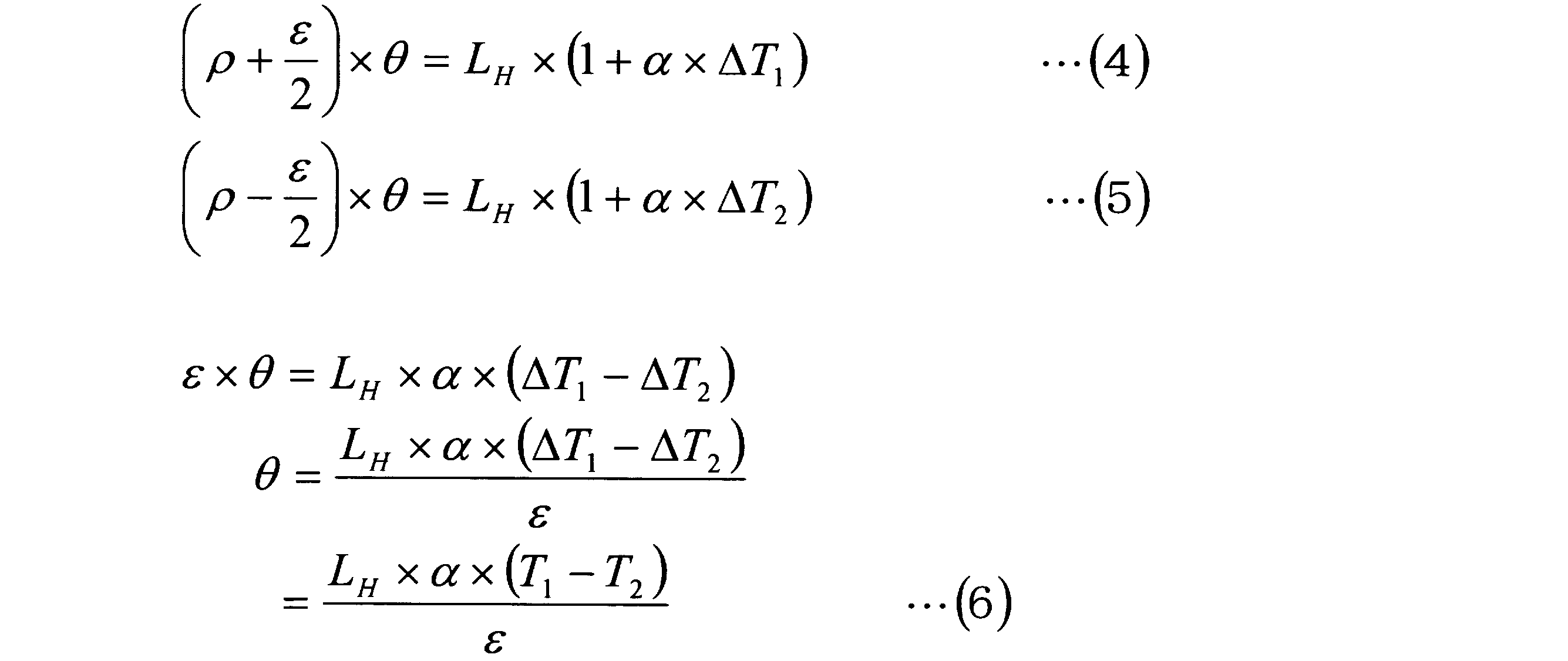

図10及び図11に基づき、本発明の実施の形態例4に係る工作機械の熱変位補正システムについて説明する。なお、図10及び図11に示す熱変位補正システムにおいて、上記実施の形態例1~3の熱変位補正システムと同様の部分については、同一の符号を付し、重複する詳細な説明は省略する。 <
Based on FIG.10 and FIG.11, the thermal displacement correction system of the machine tool which concerns on Example 4 of Embodiment of this invention is demonstrated. In the thermal displacement correction system shown in FIGS. 10 and 11, the same parts as those in the thermal displacement correction systems in the first to third embodiments are given the same reference numerals, and the detailed description thereof is omitted. .
コラム傾斜変位量算出部103では、コラム傾斜データ入力部102で入力したコラム33の傾斜データθに基づいて、コラム33の傾斜によるX軸方向の変位量である傾斜変位量δを算出する。例えば、この傾斜変位量δは、上記(8)式に傾斜データθを代入することによって算出することができる。 In the column inclination
The column inclination displacement
Claims (6)
- 工具が装着された主軸と、コラムと、前記主軸と前記コラムとの間に介設された主軸系統の支持部材と、前記コラムの前後方向であるX軸方向に移動可能なテーブルと、前記テーブルのX軸方向の位置を検出する位置検出器とを有する工作機械の熱変位補正システムにおいて、
前記位置検出器に設置され、前記位置検出器の温度を検出して温度データを出力する位置検出器温度センサと、
前記X軸方向における前記テーブルの各部に設置され、前記テーブルの各部の温度を検出して温度データを出力する複数のテーブル温度センサと、
前記位置検出器温度センサから前記温度データを入力する位置検出器温度データ入力部と、前記位置検出器温度データ入力部で入力した前記温度データに基づいて前記位置検出器の熱変位量を算出する位置検出器熱変位量算出部と、前記テーブル温度センサから前記温度データを入力するテーブル温度データ入力部と、前記テーブル温度データ入力部で入力した前記温度データに基づいて前記テーブルに生じるX軸方向の温度分布に応じた前記テーブルの熱変位量を算出するテーブル熱変位量算出部と、前記位置検出器熱変位量算出部で算出された前記位置検出器の熱変位量と前記テーブル熱変位量算出部で算出された前記テーブルの熱変位量とに基づいて前記コラムの前面を基準位置としたテーブル系統の熱変位量を算出するテーブル系統熱変位量算出部と、前記テーブル系統熱変位量算出部で算出された前記テーブル系統の熱変位量に基づいてX軸の補正量を求めてこのX軸の補正量を出力するX軸補正量出力部とを有する変位補正装置と、
を備えたことを特徴とする工作機械の熱変位補正システム。 A spindle on which a tool is mounted, a column, a support member for a spindle system interposed between the spindle and the column, a table movable in the X-axis direction which is the front-rear direction of the column, and the table A thermal displacement correction system for a machine tool having a position detector for detecting a position in the X-axis direction,
A position detector temperature sensor that is installed in the position detector and detects temperature of the position detector and outputs temperature data;
A plurality of table temperature sensors installed at each part of the table in the X-axis direction and detecting temperature of each part of the table and outputting temperature data;
A position detector temperature data input unit for inputting the temperature data from the position detector temperature sensor, and a thermal displacement amount of the position detector is calculated based on the temperature data input by the position detector temperature data input unit. A position detector thermal displacement calculation unit, a table temperature data input unit for inputting the temperature data from the table temperature sensor, and an X-axis direction generated in the table based on the temperature data input by the table temperature data input unit A table thermal displacement amount calculation unit that calculates a thermal displacement amount of the table according to the temperature distribution of the table, a thermal displacement amount of the position detector calculated by the position detector thermal displacement amount calculation unit, and the table thermal displacement amount A table system for calculating the thermal displacement amount of the table system with the front surface of the column as a reference position based on the thermal displacement amount of the table calculated by the calculation unit An X-axis correction amount output for obtaining an X-axis correction amount based on the displacement amount calculation unit and the table system thermal displacement amount calculated by the table system thermal displacement amount calculation unit and outputting the X-axis correction amount A displacement correction device having a section;
A thermal displacement correction system for machine tools, comprising: - 工具が装着された主軸と、コラムと、前記主軸と前記コラムとの間に介設された主軸系統の支持部材と、前記コラムの前後方向であるX軸方向に移動可能なテーブルと、前記テーブルのX軸方向の位置を検出する位置検出器とを有する工作機械の熱変位補正システムにおいて、
前記位置検出器に設置され、前記位置検出器の温度を検出して温度データを出力する位置検出器温度センサと、
前記X軸方向における前記テーブルの各部に設置され、前記テーブルの各部の温度を検出して温度データを出力する複数のテーブル温度センサと、
前記主軸系統の支持部材に設置され、前記主軸系統の支持部材の温度を検出して温度データを出力する支持部材温度センサと、
前記位置検出器温度センサから前記温度データを入力する位置検出器温度データ入力部と、前記位置検出器温度データ入力部で入力した前記温度データに基づいて前記位置検出器の熱変位量を算出する位置検出器熱変位量算出部と、前記テーブル温度センサから前記温度データを入力するテーブル温度データ入力部と、前記テーブル温度データ入力部で入力した前記温度データに基づいて前記テーブルに生じるX軸方向の温度分布に応じた前記テーブルの熱変位量を算出するテーブル熱変位量算出部と、前記位置検出器熱変位量算出部で算出された前記位置検出器の熱変位量と前記テーブル熱変位量算出部で算出された前記テーブルの熱変位量とに基づいてコラム前面を基準位置としたテーブル系統の熱変位量を算出するテーブル系統熱変位量算出部と、前記支持部材温度センサから前記温度データを入力する主軸系統温度データ入力部と、前記主軸系統温度データ入力部で入力した前記温度データに基づいてコラム前面を基準位置とした主軸系統の熱変位量を算出する主軸系統熱変位量算出部と、前記テーブル系統熱変位量算出部で算出された前記テーブル系統の熱変位量と前記主軸系統熱変位量算出部で算出された前記主軸系統の熱変位量とに基づいてX軸の補正量を求めてこのX軸の補正量を出力するX軸補正量出力部とを有する変位補正装置と、
を備えたことを特徴とする工作機械の熱変位補正システム。 A spindle on which a tool is mounted, a column, a support member for a spindle system interposed between the spindle and the column, a table movable in the X-axis direction which is the front-rear direction of the column, and the table A thermal displacement correction system for a machine tool having a position detector for detecting a position in the X-axis direction,
A position detector temperature sensor that is installed in the position detector and detects temperature of the position detector and outputs temperature data;
A plurality of table temperature sensors installed at each part of the table in the X-axis direction and detecting temperature of each part of the table and outputting temperature data;
A support member temperature sensor installed on a support member of the spindle system, detecting a temperature of the support member of the spindle system and outputting temperature data;
A position detector temperature data input unit for inputting the temperature data from the position detector temperature sensor, and a thermal displacement amount of the position detector is calculated based on the temperature data input by the position detector temperature data input unit. A position detector thermal displacement calculation unit, a table temperature data input unit for inputting the temperature data from the table temperature sensor, and an X-axis direction generated in the table based on the temperature data input by the table temperature data input unit A table thermal displacement amount calculation unit that calculates a thermal displacement amount of the table according to the temperature distribution of the table, a thermal displacement amount of the position detector calculated by the position detector thermal displacement amount calculation unit, and the table thermal displacement amount Table system thermal displacement that calculates the thermal displacement amount of the table system with the front surface of the column as a reference position based on the thermal displacement amount of the table calculated by the calculation unit A spindle system temperature data input section for inputting the temperature data from the support member temperature sensor; and a spindle system with a column front surface as a reference position based on the temperature data input by the spindle system temperature data input section. A spindle system thermal displacement amount calculation unit for calculating a thermal displacement amount, a thermal displacement amount of the table system calculated by the table system thermal displacement amount calculation unit, and the spindle system calculated by the spindle system thermal displacement amount calculation unit A displacement correction device having an X-axis correction amount output unit that calculates an X-axis correction amount based on the thermal displacement amount of
A thermal displacement correction system for machine tools, comprising: - 工具が装着された主軸と、コラムと、前記主軸と前記コラムとの間に介設された主軸系統の支持部材と、前記コラムの前後方向であるX軸方向に移動可能なテーブルと、前記テーブルのX軸方向の位置を検出する位置検出器とを有する工作機械の熱変位補正システムにおいて、
前記位置検出器に設置され、前記位置検出器の温度を検出して温度データを出力する位置検出器温度センサと、
前記X軸方向における前記テーブルの各部に設置され、前記テーブルの各部の温度を検出して温度データを出力する複数のテーブル温度センサと、
前記主軸系統の支持部材に設置され、前記主軸系統の支持部材の温度を検出して温度データを出力する支持部材温度センサと、
前記コラムの前面側及び後面側に設置され、前記コラムの前面側及び後面側の温度を検出して温度データを出力するコラム温度センサと、
前記位置検出器温度センサから前記温度データを入力する位置検出器温度データ入力部と、前記位置検出器温度データ入力部で入力した前記温度データに基づいて前記位置検出器の熱変位量を算出する位置検出器熱変位量算出部と、前記テーブル温度センサから前記温度データを入力するテーブル温度データ入力部と、前記テーブル温度データ入力部で入力した前記温度データに基づいて前記テーブルに生じるX軸方向の温度分布に応じた前記テーブルの熱変位量を算出するテーブル熱変位量算出部と、前記位置検出器熱変位量算出部で算出された前記位置検出器の熱変位量と前記テーブル熱変位量算出部で算出された前記テーブルの熱変位量とに基づいてコラム前面を基準位置としたテーブル系統の熱変位量を算出するテーブル系統熱変位量算出部と、前記支持部材温度センサから前記温度データを入力する主軸系統温度データ入力部と、前記主軸系統温度データ入力部で入力した前記温度データに基づいてコラム前面を基準位置とした主軸系統の熱変位量を算出する主軸系統熱変位量算出部と、前記コラム温度センサから前記温度データを入力するコラム温度データ入力部と、前記コラム温度データ入力部で入力した前記温度データに基づいて前記コラムの傾斜変位量を算出するコラム傾斜変位量算出部と、前記主軸系統熱変位量算出部で算出された前記主軸系統の熱変位量と前記コラム傾斜変位量算出部で算出された前記コラムの傾斜変位量とに基づいて主軸系統の変位量を算出する主軸系統変位量算出部と、前記テーブル系統熱変位量算出部で算出された前記テーブル系統の熱変位量と前記主軸系統変位量算出部で算出された前記主軸系統の変位量とに基づいてX軸の補正量を求めてこのX軸の補正量を出力するX軸補正量出力部とを有する変位補正装置と、
を備えたことを特徴とする工作機械の熱変位補正システム。 A spindle on which a tool is mounted, a column, a support member for a spindle system interposed between the spindle and the column, a table movable in the X-axis direction which is the front-rear direction of the column, and the table A thermal displacement correction system for a machine tool having a position detector for detecting a position in the X-axis direction,
A position detector temperature sensor that is installed in the position detector and detects temperature of the position detector and outputs temperature data;
A plurality of table temperature sensors installed at each part of the table in the X-axis direction and detecting temperature of each part of the table and outputting temperature data;
A support member temperature sensor installed on a support member of the spindle system, detecting a temperature of the support member of the spindle system and outputting temperature data;
A column temperature sensor that is installed on the front side and the rear side of the column, detects temperature on the front side and the rear side of the column, and outputs temperature data;
A position detector temperature data input unit for inputting the temperature data from the position detector temperature sensor, and a thermal displacement amount of the position detector is calculated based on the temperature data input by the position detector temperature data input unit. A position detector thermal displacement calculation unit, a table temperature data input unit for inputting the temperature data from the table temperature sensor, and an X-axis direction generated in the table based on the temperature data input by the table temperature data input unit A table thermal displacement amount calculation unit that calculates a thermal displacement amount of the table according to the temperature distribution of the table, a thermal displacement amount of the position detector calculated by the position detector thermal displacement amount calculation unit, and the table thermal displacement amount Table system thermal displacement that calculates the thermal displacement amount of the table system with the front surface of the column as a reference position based on the thermal displacement amount of the table calculated by the calculation unit A spindle system temperature data input section for inputting the temperature data from the support member temperature sensor; and a spindle system with a column front surface as a reference position based on the temperature data input by the spindle system temperature data input section. A spindle system thermal displacement calculation unit for calculating a thermal displacement amount, a column temperature data input unit for inputting the temperature data from the column temperature sensor, and the column based on the temperature data input by the column temperature data input unit. A column inclination displacement amount calculation unit for calculating an inclination displacement amount of the spindle system, a thermal displacement amount of the spindle system calculated by the spindle system thermal displacement amount calculation unit, and an inclination of the column calculated by the column inclination displacement amount calculation unit A spindle system displacement amount calculation unit that calculates a displacement amount of the spindle system based on the displacement amount, and the table system calculated by the table system thermal displacement amount calculation unit An X-axis correction amount output unit that obtains an X-axis correction amount based on the thermal displacement amount and the main-axis system displacement amount calculated by the main-shaft system displacement amount calculation unit and outputs the X-axis correction amount; A displacement correction device,
A thermal displacement correction system for machine tools, comprising: - 請求項3に記載する工作機械の熱変位補正システムにおいて、
前記主軸系統温度データ入力部では、前記支持部材温度センサ及び前記コラム温度センサから前記温度データを入力し、前記主軸系統熱変位量算出部では、前記主軸系統温度データ入力部で入力した前記支持部材温度センサ及び前記コラム温度センサの温度データに基づいてコラム前面を基準位置とした主軸系統の熱変位量を算出することを特徴とする工作機械の熱変位補正システム。 In the thermal displacement correction system for machine tools according to claim 3,
The spindle system temperature data input unit inputs the temperature data from the support member temperature sensor and the column temperature sensor, and the spindle system thermal displacement amount calculation unit inputs the support member from the spindle system temperature data input unit. A thermal displacement correction system for a machine tool, wherein a thermal displacement amount of a spindle system with a column front surface as a reference position is calculated based on a temperature sensor and temperature data of the column temperature sensor. - 工具が装着された主軸と、コラムと、前記主軸と前記コラムとの間に介設された主軸系統の支持部材と、前記コラムの前後方向であるX軸方向に移動可能なテーブルと、前記テーブルのX軸方向の位置を検出する位置検出器とを有する工作機械の熱変位補正システムにおいて、
前記位置検出器に設置され、前記位置検出器の温度を検出して温度データを出力する位置検出器温度センサと、
前記X軸方向における前記テーブルの各部に設置され、前記テーブルの各部の温度を検出して温度データを出力する複数のテーブル温度センサと、
前記主軸系統の支持部材に設置され、前記主軸系統の支持部材の温度を検出して温度データを出力する支持部材温度センサと、
前記コラムに設置され、前記コラムの傾斜角度を検出して傾斜データを出力する水準器と、
前記位置検出器温度センサから前記温度データを入力する位置検出器温度データ入力部と、前記位置検出器温度データ入力部で入力した前記温度データに基づいて前記位置検出器の熱変位量を算出する位置検出器熱変位量算出部と、前記テーブル温度センサから前記温度データを入力するテーブル温度データ入力部と、前記テーブル温度データ入力部で入力した前記温度データに基づいて前記テーブルに生じるX軸方向の温度分布に応じた前記テーブルの熱変位量を算出するテーブル熱変位量算出部と、前記位置検出器熱変位量算出部で算出された前記位置検出器の熱変位量と前記テーブル熱変位量算出部で算出された前記テーブルの熱変位量とに基づいてコラム前面を基準位置としたテーブル系統の熱変位量を算出するテーブル系統熱変位量算出部と、前記支持部材温度センサから前記温度データを入力する主軸系統温度データ入力部と、前記主軸系統温度データ入力部で入力した前記温度データに基づいてコラム前面を基準位置とした主軸系統の熱変位量を算出する主軸系統熱変位量算出部と、前記水準器から前記傾斜データを入力するコラム傾斜データ入力部と、前記コラム傾斜データ入力部で入力した前記傾斜データに基づいて前記コラムの傾斜変位量を算出するコラム傾斜変位量算出部と、前記主軸系統熱変位量算出部で算出された前記主軸系統の熱変位量と前記コラム傾斜変位量算出部で算出された前記コラムの傾斜変位量とに基づいて主軸系統の変位量を算出する主軸系統変位量算出部と、前記テーブル系統熱変位量算出部で算出された前記テーブル系統の熱変位量と前記主軸系統変位量算出部で算出された前記主軸系統の変位量とに基づいてX軸の補正量を求めてこのX軸の補正量を出力するX軸補正量出力部とを有する変位補正装置と、
を備えたことを特徴とする工作機械の熱変位補正システム。 A spindle on which a tool is mounted, a column, a support member for a spindle system interposed between the spindle and the column, a table movable in the X-axis direction which is the front-rear direction of the column, and the table A thermal displacement correction system for a machine tool having a position detector for detecting a position in the X-axis direction,
A position detector temperature sensor that is installed in the position detector and detects temperature of the position detector and outputs temperature data;
A plurality of table temperature sensors installed at each part of the table in the X-axis direction and detecting temperature of each part of the table and outputting temperature data;
A support member temperature sensor installed on a support member of the spindle system, detecting a temperature of the support member of the spindle system and outputting temperature data;
A level that is installed in the column and detects inclination angle of the column and outputs inclination data;
A position detector temperature data input unit for inputting the temperature data from the position detector temperature sensor, and a thermal displacement amount of the position detector is calculated based on the temperature data input by the position detector temperature data input unit. A position detector thermal displacement calculation unit, a table temperature data input unit for inputting the temperature data from the table temperature sensor, and an X-axis direction generated in the table based on the temperature data input by the table temperature data input unit A table thermal displacement amount calculation unit that calculates a thermal displacement amount of the table according to the temperature distribution of the table, a thermal displacement amount of the position detector calculated by the position detector thermal displacement amount calculation unit, and the table thermal displacement amount Table system thermal displacement that calculates the thermal displacement amount of the table system with the front surface of the column as a reference position based on the thermal displacement amount of the table calculated by the calculation unit A spindle system temperature data input section for inputting the temperature data from the support member temperature sensor; and a spindle system with a column front surface as a reference position based on the temperature data input by the spindle system temperature data input section. A spindle system thermal displacement amount calculation unit for calculating a thermal displacement amount, a column inclination data input unit for inputting the inclination data from the level, and the column data based on the inclination data input by the column inclination data input unit. Column inclination displacement amount calculation unit for calculating the inclination displacement amount, thermal displacement amount of the spindle system calculated by the spindle system thermal displacement amount calculation unit, and inclination displacement of the column calculated by the column inclination displacement amount calculation unit A spindle system displacement amount calculation unit that calculates a displacement amount of the spindle system based on the amount, and a thermal displacement amount of the table system calculated by the table system thermal displacement amount calculation unit A displacement correction device having an X-axis correction amount output unit that obtains an X-axis correction amount based on the displacement amount of the main shaft system calculated by the main shaft system displacement amount calculation unit and outputs the X-axis correction amount When,
A thermal displacement correction system for machine tools, comprising: - 請求項5に記載する工作機械の熱変位補正システムにおいて、
前記コラムに設置され、前記コラムの温度を検出して温度データを出力するコラム温度センサを有し、
前記主軸系統温度データ入力部では、前記支持部材温度センサ及び前記コラム温度センサから前記温度データを入力し、前記主軸系統熱変位量算出部では、前記主軸系統温度データ入力部で入力した前記支持部材温度センサ及び前記コラム温度センサの温度データに基づいてコラム前面を基準位置とした主軸系統の熱変位量を算出することを特徴とする工作機械の熱変位補正システム。 In the thermal displacement correction system for a machine tool according to claim 5,
A column temperature sensor that is installed in the column and detects temperature of the column and outputs temperature data;
The spindle system temperature data input unit inputs the temperature data from the support member temperature sensor and the column temperature sensor, and the spindle system thermal displacement amount calculation unit inputs the support member from the spindle system temperature data input unit. A thermal displacement correction system for a machine tool, wherein a thermal displacement amount of a spindle system with a column front surface as a reference position is calculated based on a temperature sensor and temperature data of the column temperature sensor.
Priority Applications (3)
| Application Number | Priority Date | Filing Date | Title |
|---|---|---|---|
| US13/823,005 US20130223946A1 (en) | 2010-10-21 | 2011-10-05 | System for correcting thermal displacement of machine tool |
| KR1020137007898A KR20130069777A (en) | 2010-10-21 | 2011-10-05 | System for correcting thermal displacement of machine tool |
| CN2011800462842A CN103153534A (en) | 2010-10-21 | 2011-10-05 | System for correcting thermal displacement of machine tool |
Applications Claiming Priority (2)
| Application Number | Priority Date | Filing Date | Title |
|---|---|---|---|
| JP2010-236424 | 2010-10-21 | ||
| JP2010236424A JP2012086326A (en) | 2010-10-21 | 2010-10-21 | System for correcting thermal displacement of machine tool |
Publications (1)
| Publication Number | Publication Date |
|---|---|
| WO2012053353A1 true WO2012053353A1 (en) | 2012-04-26 |
Family
ID=45975072
Family Applications (1)
| Application Number | Title | Priority Date | Filing Date |
|---|---|---|---|
| PCT/JP2011/072918 WO2012053353A1 (en) | 2010-10-21 | 2011-10-05 | System for correcting thermal displacement of machine tool |
Country Status (6)
| Country | Link |
|---|---|
| US (1) | US20130223946A1 (en) |
| JP (1) | JP2012086326A (en) |
| KR (1) | KR20130069777A (en) |
| CN (1) | CN103153534A (en) |
| TW (1) | TW201221282A (en) |
| WO (1) | WO2012053353A1 (en) |
Cited By (2)
| Publication number | Priority date | Publication date | Assignee | Title |
|---|---|---|---|---|
| EP2824524A3 (en) * | 2013-07-02 | 2015-02-25 | Jtekt Corporation | Thermal displacement correction method and thermal displacement correction unit |
| CN109623490A (en) * | 2018-12-14 | 2019-04-16 | 重庆大学 | A kind of the Thermal Error measuring system and method for lathe |
Families Citing this family (22)
| Publication number | Priority date | Publication date | Assignee | Title |
|---|---|---|---|---|
| JP6155946B2 (en) * | 2013-08-07 | 2017-07-05 | 株式会社ジェイテクト | Method for determining linear expansion coefficient of each member of machine tool and thermal displacement correction device for machine tool |
| CN103941642B (en) * | 2014-04-14 | 2017-01-04 | 西安交通大学 | Thermal Error Intelligent Measurement compensates system |
| JP6001211B1 (en) * | 2014-10-29 | 2016-10-05 | ヤマザキマザック株式会社 | Machine tool with thermal displacement correction amount setting change device |
| JP5987073B2 (en) * | 2015-02-12 | 2016-09-06 | ファナック株式会社 | Work positioning device using imaging unit |
| JP2016200928A (en) | 2015-04-09 | 2016-12-01 | ファナック株式会社 | Management system for machine tool |
| JP6280078B2 (en) * | 2015-05-11 | 2018-02-14 | ファナック株式会社 | Thermal displacement compensation training device for machine tools |
| CN105397560B (en) * | 2015-12-22 | 2018-07-06 | 重庆大学 | One kind is dry to cut chain digital control gear hobbing machine bed and workpiece method for thermal deformation error compensation |
| US11353842B2 (en) * | 2016-03-28 | 2022-06-07 | Doosan Machine Tools Co., Ltd. | Apparatus and method for automatically converting thermal displacement compensation parameters of machine tool |
| JP6955655B2 (en) * | 2016-11-14 | 2021-10-27 | 株式会社ニイガタマシンテクノ | Machine tool temperature control device |
| CN106736848B (en) * | 2016-12-13 | 2019-04-12 | 西安交通大学 | Numerically controlled lathe Thermal Error measures compensation system and compensation method |
| JP6691087B2 (en) | 2017-10-04 | 2020-04-28 | ファナック株式会社 | Thermal displacement correction system |
| US10843278B2 (en) * | 2017-11-17 | 2020-11-24 | Lamons Gasket Company | Kammprofile milling machine |
| CN107791043A (en) * | 2017-12-01 | 2018-03-13 | 江苏新瑞重工科技有限公司 | Multistation shape extrusion lathe |
| JP6673950B2 (en) * | 2018-01-31 | 2020-04-01 | ファナック株式会社 | Reference temperature setting device, reference temperature setting method and reference temperature setting program |
| JP6737840B2 (en) * | 2018-06-19 | 2020-08-12 | ファナック株式会社 | Adjustment necessity judgment device |
| JP6890110B2 (en) * | 2018-10-31 | 2021-06-18 | Dmg森精機株式会社 | Machine tool thermal displacement correction method |
| CN110579999A (en) * | 2019-08-27 | 2019-12-17 | 东莞市巨冈机械工业有限公司 | z-direction zero drift error compensation method based on triaxial drilling and tapping numerical control machine tool, electronic equipment and computer readable storage medium |
| JP2021104564A (en) * | 2019-12-26 | 2021-07-26 | ファナック株式会社 | Thermal displacement correction device |
| DE102020204232B4 (en) * | 2020-04-01 | 2023-05-17 | P&L Gmbh & Co. Kg | Machine tool with high-precision machining capability and operating method |
| CN111895947A (en) * | 2020-07-16 | 2020-11-06 | 中国航空工业集团公司北京航空精密机械研究所 | Temperature compensation system and temperature compensation method based on three-coordinate measuring machine |
| CN112658803B (en) * | 2020-12-16 | 2023-09-29 | 东莞市埃弗米数控设备科技有限公司 | Milling head machining mechanism with temperature detection function and temperature detection compensation method thereof |
| TWI814648B (en) * | 2022-11-24 | 2023-09-01 | 國立勤益科技大學 | Thermal displacement measurement device |
Citations (6)
| Publication number | Priority date | Publication date | Assignee | Title |
|---|---|---|---|---|
| JPH05248854A (en) * | 1992-03-05 | 1993-09-28 | Fujitsu Ltd | Super-precise measuring method for displacement amount of movable stage |
| JP2001054839A (en) * | 1999-08-20 | 2001-02-27 | Okuma Corp | Thermal displacement reducing device for machine |
| JP2006239854A (en) * | 2005-02-04 | 2006-09-14 | Nagase Integrex Co Ltd | Machine tool |
| JP2006281420A (en) * | 2005-04-05 | 2006-10-19 | Okuma Corp | Heat displacement compensating method of nc machine tool |
| JP2008246621A (en) * | 2007-03-30 | 2008-10-16 | Brother Ind Ltd | Machine tool, control program for correcting thermal expansion, and storage medium |
| JP4359573B2 (en) * | 2005-03-31 | 2009-11-04 | オークマ株式会社 | Machine tool thermal displacement compensation method |
Family Cites Families (7)
| Publication number | Priority date | Publication date | Assignee | Title |
|---|---|---|---|---|
| US4370720A (en) * | 1970-12-28 | 1983-01-25 | Hyatt Gilbert P | Coordinate rotation for numerical control system |
| JPS62213945A (en) * | 1986-03-12 | 1987-09-19 | Toshiba Mach Co Ltd | Thermal displacement correcting device for machine tool |
| JPS62248009A (en) * | 1986-04-22 | 1987-10-29 | Mitsubishi Electric Corp | Numerical controller |
| JP3792266B2 (en) * | 1994-06-16 | 2006-07-05 | 森精機興産株式会社 | Method and apparatus for correcting thermal displacement of machine tool |
| JP3745225B2 (en) * | 1997-12-26 | 2006-02-15 | 三菱電機株式会社 | Laser processing equipment |
| DE102004044838A1 (en) * | 2004-09-13 | 2006-03-30 | Chiron-Werke Gmbh & Co Kg | Method for compensation of thermal displacements |
| JP5337636B2 (en) * | 2008-09-05 | 2013-11-06 | 株式会社森精機製作所 | Machining status monitoring method and machining status monitoring device |
-
2010
- 2010-10-21 JP JP2010236424A patent/JP2012086326A/en active Pending
-
2011
- 2011-10-05 WO PCT/JP2011/072918 patent/WO2012053353A1/en active Application Filing
- 2011-10-05 KR KR1020137007898A patent/KR20130069777A/en not_active Application Discontinuation
- 2011-10-05 US US13/823,005 patent/US20130223946A1/en not_active Abandoned
- 2011-10-05 CN CN2011800462842A patent/CN103153534A/en active Pending
- 2011-10-06 TW TW100136324A patent/TW201221282A/en unknown
Patent Citations (6)
| Publication number | Priority date | Publication date | Assignee | Title |
|---|---|---|---|---|
| JPH05248854A (en) * | 1992-03-05 | 1993-09-28 | Fujitsu Ltd | Super-precise measuring method for displacement amount of movable stage |
| JP2001054839A (en) * | 1999-08-20 | 2001-02-27 | Okuma Corp | Thermal displacement reducing device for machine |
| JP2006239854A (en) * | 2005-02-04 | 2006-09-14 | Nagase Integrex Co Ltd | Machine tool |
| JP4359573B2 (en) * | 2005-03-31 | 2009-11-04 | オークマ株式会社 | Machine tool thermal displacement compensation method |
| JP2006281420A (en) * | 2005-04-05 | 2006-10-19 | Okuma Corp | Heat displacement compensating method of nc machine tool |
| JP2008246621A (en) * | 2007-03-30 | 2008-10-16 | Brother Ind Ltd | Machine tool, control program for correcting thermal expansion, and storage medium |
Cited By (2)
| Publication number | Priority date | Publication date | Assignee | Title |
|---|---|---|---|---|
| EP2824524A3 (en) * | 2013-07-02 | 2015-02-25 | Jtekt Corporation | Thermal displacement correction method and thermal displacement correction unit |
| CN109623490A (en) * | 2018-12-14 | 2019-04-16 | 重庆大学 | A kind of the Thermal Error measuring system and method for lathe |
Also Published As
| Publication number | Publication date |
|---|---|
| TW201221282A (en) | 2012-06-01 |
| JP2012086326A (en) | 2012-05-10 |
| US20130223946A1 (en) | 2013-08-29 |
| CN103153534A (en) | 2013-06-12 |
| KR20130069777A (en) | 2013-06-26 |
Similar Documents
| Publication | Publication Date | Title |
|---|---|---|
| WO2012053353A1 (en) | System for correcting thermal displacement of machine tool | |
| WO2011083596A1 (en) | Machine displacement adjustment system for machine tools | |
| US7245983B2 (en) | Method and apparatus for correcting thermal displacement of machine tool | |
| JP5259617B2 (en) | Apparatus and method for measuring load applied to friction stir welding tool | |
| KR101074206B1 (en) | Heat dislocation compensation method of machine tool, heat dislocation compensation device of machine tool and computer readable medium in which program for heat dislocation compensation is stored | |
| JP5418272B2 (en) | Thermal displacement correction method and thermal displacement correction apparatus for machine tool | |
| Yun et al. | Thermal error analysis for a CNC lathe feed drive system | |
| JP4359573B2 (en) | Machine tool thermal displacement compensation method | |
| JP3792266B2 (en) | Method and apparatus for correcting thermal displacement of machine tool | |
| WO2012053352A1 (en) | Load inertia estimation method and control parameter adjustment method | |
| JP4559277B2 (en) | NC machine tool thermal displacement compensation method | |
| KR19990076152A (en) | Measurement and correction system of heat deformation error of machine tool | |
| US20130169208A1 (en) | Path display apparatus considering correction data | |
| JP5387838B2 (en) | Thermal displacement compensation method and thermal displacement compensation device for numerically controlled machine tool | |
| WO2016147979A1 (en) | Machine tool | |
| JP3448733B2 (en) | Linear actuator mechanism in vacuum | |
| JP2004042260A (en) | Thermal displacement correcting method for machine tool, and device thereof | |
| JP4503148B2 (en) | Compensator for feeding mechanism of numerically controlled machine tool and numerically controlled machine tool | |
| TW201832456A (en) | Work conveyance control system and motion guide device | |
| JP4878949B2 (en) | Calculation method of thermal displacement amount used for thermal displacement correction of machine tool, calculation system of thermal displacement amount, thermal displacement correction method of machine tool, and thermal displacement correction system | |
| JP4082598B2 (en) | Method and apparatus for correcting thermal displacement of numerically controlled machine tool | |
| JP4939388B2 (en) | Feed-forward control device | |
| JP5334932B2 (en) | Parameter setting method and parameter setting device | |
| KR20170079274A (en) | Device for compensating thermal displacement of feed driver for a machine tool and method thereof | |
| JP4842903B2 (en) | Numerical control apparatus and numerical control method |
Legal Events
| Date | Code | Title | Description |
|---|---|---|---|
| WWE | Wipo information: entry into national phase |
Ref document number: 201180046284.2 Country of ref document: CN |
|
| 121 | Ep: the epo has been informed by wipo that ep was designated in this application |
Ref document number: 11834193 Country of ref document: EP Kind code of ref document: A1 |
|
| ENP | Entry into the national phase |
Ref document number: 20137007898 Country of ref document: KR Kind code of ref document: A |
|
| NENP | Non-entry into the national phase |
Ref country code: DE |
|
| WWE | Wipo information: entry into national phase |
Ref document number: 13823005 Country of ref document: US |
|
| 122 | Ep: pct application non-entry in european phase |
Ref document number: 11834193 Country of ref document: EP Kind code of ref document: A1 |