WO2012053085A1 - ストレージ制御装置およびストレージ制御方法 - Google Patents
ストレージ制御装置およびストレージ制御方法 Download PDFInfo
- Publication number
- WO2012053085A1 WO2012053085A1 PCT/JP2010/068561 JP2010068561W WO2012053085A1 WO 2012053085 A1 WO2012053085 A1 WO 2012053085A1 JP 2010068561 W JP2010068561 W JP 2010068561W WO 2012053085 A1 WO2012053085 A1 WO 2012053085A1
- Authority
- WO
- WIPO (PCT)
- Prior art keywords
- data
- write
- storage
- hdd
- storage area
- Prior art date
- Legal status (The legal status is an assumption and is not a legal conclusion. Google has not performed a legal analysis and makes no representation as to the accuracy of the status listed.)
- Ceased
Links
Images














Classifications
-
- G—PHYSICS
- G06—COMPUTING OR CALCULATING; COUNTING
- G06F—ELECTRIC DIGITAL DATA PROCESSING
- G06F11/00—Error detection; Error correction; Monitoring
- G06F11/07—Responding to the occurrence of a fault, e.g. fault tolerance
- G06F11/08—Error detection or correction by redundancy in data representation, e.g. by using checking codes
- G06F11/10—Adding special bits or symbols to the coded information, e.g. parity check, casting out 9's or 11's
- G06F11/1076—Parity data used in redundant arrays of independent storages, e.g. in RAID systems
- G06F11/1084—Degraded mode, e.g. caused by single or multiple storage removals or disk failures
-
- G—PHYSICS
- G06—COMPUTING OR CALCULATING; COUNTING
- G06F—ELECTRIC DIGITAL DATA PROCESSING
- G06F11/00—Error detection; Error correction; Monitoring
- G06F11/07—Responding to the occurrence of a fault, e.g. fault tolerance
- G06F11/08—Error detection or correction by redundancy in data representation, e.g. by using checking codes
- G06F11/10—Adding special bits or symbols to the coded information, e.g. parity check, casting out 9's or 11's
-
- G—PHYSICS
- G06—COMPUTING OR CALCULATING; COUNTING
- G06F—ELECTRIC DIGITAL DATA PROCESSING
- G06F11/00—Error detection; Error correction; Monitoring
- G06F11/07—Responding to the occurrence of a fault, e.g. fault tolerance
- G06F11/16—Error detection or correction of the data by redundancy in hardware
- G06F11/1658—Data re-synchronization of a redundant component, or initial sync of replacement, additional or spare unit
- G06F11/1662—Data re-synchronization of a redundant component, or initial sync of replacement, additional or spare unit the resynchronized component or unit being a persistent storage device
-
- G—PHYSICS
- G06—COMPUTING OR CALCULATING; COUNTING
- G06F—ELECTRIC DIGITAL DATA PROCESSING
- G06F11/00—Error detection; Error correction; Monitoring
- G06F11/07—Responding to the occurrence of a fault, e.g. fault tolerance
- G06F11/16—Error detection or correction of the data by redundancy in hardware
- G06F11/20—Error detection or correction of the data by redundancy in hardware using active fault-masking, e.g. by switching out faulty elements or by switching in spare elements
- G06F11/2097—Error detection or correction of the data by redundancy in hardware using active fault-masking, e.g. by switching out faulty elements or by switching in spare elements maintaining the standby controller/processing unit updated
-
- G—PHYSICS
- G06—COMPUTING OR CALCULATING; COUNTING
- G06F—ELECTRIC DIGITAL DATA PROCESSING
- G06F2201/00—Indexing scheme relating to error detection, to error correction, and to monitoring
- G06F2201/82—Solving problems relating to consistency
Definitions
- the present invention relates to a storage control device and a storage control method for controlling a storage device.
- Redundant Array of Inexpensive Disks (RAID) 3, 5 and other redundant storage systems, when a disk device fails, disconnects the failed disk device. When a failed disk device is disconnected, the storage system records and updates data using the remaining disk devices except the disconnected disk device.
- multi-dead state a state in which another disk device is disconnected from a state in which a disk device in the storage system has failed and lost redundancy is referred to as a “multi-dead state”.
- failures that cause the disk device to be disconnected include thermal off-track, contamination, noise, and poor contact. Failures such as thermal off-track, contamination, noise, and poor contact of a disk device are often recovered by a hard reset or a power cycle (power off / on).
- the disk device can be restored as a normally operating disk device. For this reason, when recovering a storage system that has entered a multi-dead state, for example, a hard reset of the storage system is performed to restore the state before the multi-dead state.
- patent documents 1 to 3 are disclosed as techniques for disclosing a technique for recovering a storage system in which a failure has occurred in a disk device.
- An object of the present invention is to provide a storage control device and a storage control method capable of ensuring data consistency between storage devices in order to solve the above-described problems caused by the prior art.
- the disclosed storage control device and storage control method store, for each data group, each data of the data group and a correction code generated from the data group as a storage destination.
- a write request is received for a storage device in the system that stores the storage devices differently, and when the write request is received, the data stored in the storage area requested by the storage device and the data are The correction code stored in the storage device, which is the generation source, is copied from the storage device to a specific storage area, and the data and the correction code are copied to the specific storage area, and then the document is written. It is determined whether or not the storage device for which the write process for the write request has been executed has been restarted, and it is determined that the storage device has been restarted.
- the data copied to the specific storage area is written to the requested storage area of the storage apparatus, and the correction code copied to the specific storage area is stored in the storage apparatus that is the copy source of the correction code. Write to the area.
- the disclosed storage control device and storage control method store, for each data group, each data of the data group and a correction code generated from the data group as a storage destination.
- a write request to a storage device in a system that stores data in different storage devices is received and the write request is received, a request from the storage device is made to the control unit that accesses the storage device in the system. Instructed to copy the data stored in the previous storage area and the correction code stored in the storage device, which is generated from the data, to a specific storage area, and the specified data After the correction code is copied to the specific storage area, the storage device that has executed the write process for the write request is restarted.
- the controller copies the data copied to the specific storage area to the requested storage area of the storage apparatus and The correction code copied to the specific storage area is instructed to be written in the storage area of the storage device that is the copy source of the correction code.
- This storage control device and storage control method has an effect of ensuring data consistency between storage devices.
- FIG. 1 is an explanatory diagram showing an example of a storage system 100 according to a first embodiment
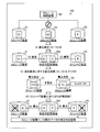
- FIG. 3 is an explanatory diagram of an example of the storage control technique according to the first embodiment
- 2 is a block diagram showing a hardware configuration of a storage system 300 according to the first embodiment.
- FIG. It is explanatory drawing which shows the specific example of management data 410,420,430.
- 2 is a block diagram showing a functional configuration of a storage control apparatus 101 according to the first embodiment.
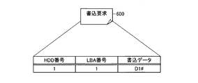
- FIG. 5 is an explanatory diagram showing a specific example of a write request 600.
- FIG. 6 is an explanatory diagram showing a specific example of a writing state table 700.
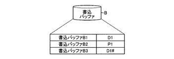
- FIG. 5 is an explanatory diagram showing a specific example of a write buffer B.
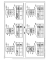
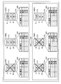
- FIG. 6 is an explanatory diagram (part 1) showing a transition example of the storage contents of LBA1 of HDD1 to HDD3.
- FIG. 6 is an explanatory diagram (part 2) showing a transition example of the storage contents of LBA1 of HDD1 to HDD3.
- FIG. 11 is an explanatory diagram (part 3) illustrating a transition example of the storage contents of the LBA1 of the HDD1 to HDD3;
- FIG. 14 is an explanatory diagram (part 4) illustrating a transition example of the storage contents of the LBA1 of the HDD1 to HDD3;
- FIG. 10 is an explanatory diagram (Part 5) showing a transition example of the stored contents of LBA1 of HDD1 to HDD3.
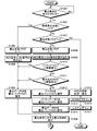
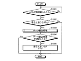
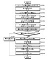
- 6 is a flowchart (part 1) illustrating an example of a data copy processing procedure of the storage control device according to the first embodiment; 6 is a flowchart (part 2) illustrating an example of a data copy processing procedure of the storage control apparatus according to the first embodiment; 4 is a flowchart showing an example of a system restoration processing procedure of the storage control apparatus 101 according to the first embodiment. It is a flowchart which shows an example of the specific process sequence of the data writing process of step S1803.
- 3 is a block diagram showing a hardware configuration of a storage system 2000 according to a second embodiment.
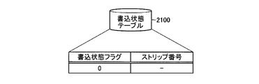
- FIG. 5 is an explanatory diagram showing a specific example of a writing state table 2100.
- FIG. 5 is a flowchart (part 1) illustrating an example of a storage control processing procedure of the storage control apparatus 101 in a redundant configuration.
- 12 is a flowchart (part 2) illustrating an example of a storage control processing procedure of the storage control apparatus 101 in a redundant configuration.
- 12 is a flowchart (part 3) illustrating an example of a storage control processing procedure of the storage control apparatus 101 in a redundant configuration.
- 10 is a flowchart (part 1) illustrating an example of a storage control processing procedure of the storage control apparatus 101 in a non-redundant configuration.
- FIG. 12 is a flowchart (part 2) illustrating an example of a storage control processing procedure of the storage control apparatus 101 in a non-redundant configuration. It is explanatory drawing (the 3) which shows the update example of management data 410,420,430. 4 is a flowchart illustrating an example of a system restoration processing procedure of the storage control apparatus 101.
- FIG. 1 is an explanatory diagram of an example of the storage system 100 according to the first embodiment.
- the storage system 100 includes a storage control device 101 and storage devices S1 to S3.
- the storage control device 101 is a computer that controls the storage devices S1 to S3.
- the storage devices S1 to S3 are storage devices that store data.
- the storage devices S1 to S3 include storage media such as a hard disk, an optical disk, a flash memory, and a magnetic tape, for example.
- the storage system 100 is a redundant system such as RAID 3 or 5.
- the storage system 100 stores each data in the data group and a correction code generated from each data in the data group in a distributed manner so that the storage devices at the storage destinations are different.
- a data group is a set of data related to each other. Each data is, for example, data in bit units, byte units, and block (sector) units.
- the correction code is a redundant code whose data is the data constituting the data group.
- the correction code one that can restore any data of the data group of the generation source from the remaining data of the data group and the correction code can be used.
- the correction code is realized using a parity, a Hamming code, an ECC (Error Correcting Code), a CRC (Cyclic Redundancy Check) code, or the like.
- ECC Error Correcting Code
- CRC Cyclic Redundancy Check
- Parity data P is data obtained by taking an exclusive OR of data D1 and data D2.
- the parity data P obtained by taking the exclusive OR of the data D1 and the data D2 is expressed as the following formula (1).
- xor represents exclusive OR.
- the storage device in which the failure has occurred is disconnected.
- To disconnect a storage device is to stop access to the storage device.
- the storage system 100 changes from a redundant configuration to a non-redundant configuration.
- the redundant configuration is a state in which data redundancy is ensured.
- the non-redundant configuration is a state in which the storage device in which a failure has occurred is disconnected from the redundant configuration and data redundancy is lost.
- the storage system 100 when a failure occurs in the storage device S2, the storage system 100 changes from a redundant configuration to a non-redundant configuration, and data D2 cannot be read from the storage device S2. In this case, the storage system 100 takes the exclusive OR of the data D1 stored in the storage device S1 and the parity data P stored in the storage device S3 as shown in the following formula (2). To restore.
- the storage system when the storage system is further disconnected from the non-redundant configuration (multi-dead state), the system goes down because the lost data cannot be restored.
- the system down is a state in which data reading and writing cannot be normally performed.
- the storage control device 101 reads data D1 from the storage device S1.
- the storage control device 101 reads the parity data P from the storage device S3.
- the storage control device 101 calculates the data D2 by taking the exclusive OR of the data D1 read from each storage device and the parity data P. As a result, the data D2 stored in the disconnected storage device S2 is restored.
- the storage system 100 when updating the data D1 to the data D1 #, the data consistency between the storage apparatuses is ensured to restore the missing data (data D2 in the above example), and the parity data is updated. Also do it.
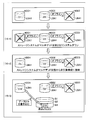
- data writing to the storage device may fail due to failures such as thermal off-track, contamination, noise, and poor contact.
- Examples of writing failures when updating the data D1 to the data D1 # include the following (a) to (c).
- the data stored in the storage device S1 is data D1 #.
- the data stored in the storage device S3 becomes data Px different from both the parity data P and the parity data P # (Px ⁇ P, P #). Further, if the writing of the parity data P # to the storage device S3 fails, the storage device S3 is disconnected from the storage system 100. As a result, the storage system 100 enters a multi-dead state from a non-redundant configuration and goes down.
- the data stored in the storage device S1 is data D1 #.
- the data stored in the storage device S3 remains the parity data P. Further, if the writing of the parity data P # to the storage device S3 fails, the storage device S3 is disconnected from the storage system 100. As a result, the storage system 100 enters a multi-dead state from a non-redundant configuration and goes down.
- the storage system 100 becomes a multi-dead state from a non-redundant configuration due to a write failure, and the system goes down.
- storage device failures such as thermal off-track, contamination, noise, and contact failure are often recovered by performing a hard reset or power OFF / ON for the storage device.
- the storage system 100 it is possible to return to the non-redundant configuration immediately before the system down by performing a hard reset or power OFF / ON for the storage device (storage device S1 or S3) that has been disconnected due to a write failure. .
- the storage system 100 is returned to the non-redundant configuration immediately before the system is down, the data consistency between the storage apparatuses S1 and S3 is not maintained. It has become.
- the data stored in the storage device S1 is “Dx ⁇ D1”, and the parity data stored in the storage device S3 is based on the data D1 stored in the storage device S1.
- P D1 xor D2.
- the data stored in the storage device S1 is “D1 #”, and the parity data stored in the storage device S3 is “P” based on D1 stored in the storage device S1. It is. For this reason, even if the exclusive OR of the data D1 # and the parity data P is taken as shown in the following formula (5), the data D2 cannot be restored.
- the pre-update data and parity data are saved in a specific storage area.
- the saved data and parity data are returned to the saving source to prevent data inconsistency between the storage apparatuses due to the writing failure.
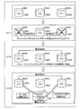
- FIG. 2 is an explanatory diagram of an example of the storage control method according to the first embodiment.
- the case where the data D1 stored in the storage device S1 is updated to the data D1 # in the non-redundant storage system 100 from which the storage device S2 shown in FIG. 1 is disconnected will be described as an example.
- the storage control apparatus 101 accepts a write request.
- the write request includes data D1 # to be written to the storage device S1 and the address of the storage area of the requested storage device S1.
- the storage control apparatus 101 may accept a write request from an external computer, or may accept a write request by a user operation input.
- the storage control device 101 When the storage control device 101 receives a write request, the storage control device 101 obtains data D1 stored in the storage area of the storage device S1 corresponding to the write request and parity data P having the data D1 as a generation source. The data is copied to a specific storage area 200. Specifically, for example, the storage control apparatus 101 reads data D1 from the storage apparatus S1 and writes it in a specific storage area 200. Further, the storage control device 101 reads the parity data P from the storage device S3 and writes it in the specific storage area 200.
- the specific storage area 200 is a non-volatile storage area that is different from the storage area of each data of the data group stored in the storage system 100 and the storage area of the parity data generated from the data group.
- the specific storage area 200 may be provided in the storage control apparatus 101, or may be provided in each of the storage apparatuses S1 to S3.
- the storage device S1 or S3 that has failed to write is disconnected from the storage system 100 and enters the multi-dead state, and the storage system 100 goes down.
- writing of the parity data P # to the storage device S3 has failed and a part of the parity data P # cannot be written to the storage device S3.
- the disconnected storage apparatus S3 is restarted to return the storage system 100 to the non-redundant configuration immediately before the system down.
- the storage apparatus S3 is restarted as a normally operating storage apparatus as a result of the restart of the storage apparatus S3.
- the storage control apparatus 101 determines whether the storage apparatus disconnected in (3) has been restarted. Specifically, for example, the storage control apparatus 101 determines that the storage apparatus S3 has been restarted by receiving a restart completion notification from the storage apparatus S3.
- the storage control apparatus 101 When the storage apparatus S1 or S3 is restarted, the storage control apparatus 101 writes the data D1 copied to the specific storage area 200 into the copy source storage area of the storage apparatus S1. Further, the storage control apparatus 101 writes the parity data P copied to the specific storage area 200 into the copy source storage area of the storage apparatus S3.
- the data before update and the parity data are saved in the specific storage area 200 when updating the data accompanied by the update of the parity data.
- the data saved between the specific storage areas 200 and the parity data are returned to the storage area of the save source, so that there is no data loss between the storage apparatuses due to the write failure. Matching can be prevented.
- a failure such as a thermal off-track is recovered by restarting the storage device, and data before update and parity data are stored in a specific storage unit in units of write requests.
- the area 200 is temporarily saved.
- data between storage devices can be restored by returning the saved data and parity data to the save source storage area after restarting the storage device. It is possible to maintain consistency.
- the data D1 and the parity data P saved in the specific storage area 200 are returned to the save-source storage area, respectively, so that the data inconsistency between the storage apparatuses S1 and S3 due to the write failure is eliminated.
- the data D2 can be restored by the returned data D1 and the parity data P.
- RAID 3 is a method in which a data group is divided and recorded on a plurality of HDDs (Hard Disk Drives), and parity data generated from the data group is recorded on a dedicated HDD (so-called parity drive).
- the number of HDDs in the storage system 300 is three HDDs 1 to 3 will be described as an example, but the number of HDDs included in the storage system 300 is not limited to this. In the case of the RAID 3 storage system 300, any number of HDDs can be adopted as long as it is three or more including one parity drive.
- FIG. 3 is a block diagram of a hardware configuration of the storage system 300 according to the first embodiment.
- the storage system 300 includes a CPU (Central Processing Unit) 301, a main memory 302, a display controller 303, a display 304, a communication controller 305, a storage controller 101, and HDD1 to HDD3. ing.
- CPU Central Processing Unit
- the CPU 301 controls the storage system 300 in an integrated manner.
- the main memory 302 includes a RAM (Random Access Memory).
- the CPU 301 loads and starts up an OS (Operating System) of the storage system 300 on the main memory 302.
- OS Operating System
- the display controller 303 performs display control of the display 304 according to the control of the CPU 301.
- the display 304 displays data such as a document, an image, and function information as well as a cursor, an icon, or a tool box.
- a CRT, a TFT liquid crystal display, a plasma display, or the like can be adopted as the display 304.
- the communication controller 305 is connected to a network 320 such as a LAN (Local Area Network), a WAN (Wide Area Network), or the Internet through a communication line, and is connected to an external computer via the network 320.
- the communication controller 305 controls an internal interface with the network 320 and controls data input / output from an external computer.
- the storage system 300 may include an input device such as a keyboard and a mouse, and an output device such as a scanner and a printer.
- the storage control apparatus 101 includes a processor 306, a memory 307, a nonvolatile memory 308, an HDD controller 309, and a bus controller 310.
- the processor 306 executes various programs such as the storage control program stored in the memory 307.
- the processor 306 controls access to the HDD 1 to HDD 3 via the HDD controller 309. In addition, the processor 306 controls connection with the HDDs 1 to 3 via the HDD controller 309. In the following description, connecting the storage control device 101 and each of the HDD1 to HDD3 is referred to as “online”, and disconnecting the storage control device 101 from the HDD1 to HDD3 is referred to as “offline”.
- the non-volatile memory 308 is a storage medium having a characteristic that the stored contents are not erased even when the power supply from the power source is cut off.
- the nonvolatile memory 308 is, for example, an NVRAM (Non Volatile RAM), a FLASH memory, or the like.
- the HDD controller 309 accesses the HDD1 to HDD3 under the control of the processor 306.
- the bus controller 310 controls data exchange between the storage control apparatus 101 and the CPU 301.
- HDD1 to HDD3 are storage devices in which a magnetic head reads / writes data by rotating a disk (hard disk) coated with a magnetic material at high speed.
- HDD1 to HDD3 correspond to the storage devices S1 to S3 described above, for example.
- the storage areas of the HDD1 to HDD3 are divided into data areas 311, 312, 313 and system areas 314, 315, 316.
- the capacities of the data areas 311, 312, 313 and the system areas 314, 315, 316 are variable within the range of the data capacities of the HDD 1 to HDD 3.
- the processor 306 can access the system areas 314 to 316 of the HDDs 1 to 3 via the HDD controller 309, not limited to offline and online.
- HDD1 and HDD2 are HDDs that store data in a data group in a distributed manner
- HDD3 is an HDD (parity drive) that stores parity data that is the exclusive OR of the data in the data group. It is.
- Data D1 to Dn are distributed and stored in the data areas 311 and 312 of the HDD1 and HDD2.
- Parity data P1 to Pm are stored in the data area 313 of the HDD 3.
- the data D1 and D2 are distributed and stored in the data areas 311 and 312 of the HDD1 and HDD2, and the parity data P1 that is the exclusive OR of the data D1 and D2 is stored in the data area 313 of the HDD3.
- the data is, for example, data obtained by dividing the OS, application program, user information, and the like in the storage system 300. Further, the data size of each data is, for example, a bit unit or a byte unit.
- Each data of the data group and parity data generated from the data group are managed by assigning, for example, the same LBA (Logical Block Addressing) number.
- LBA Logical Block Addressing
- LBA is a system in which serial numbers are assigned to all sectors in a hard disk, and sectors are designated by the serial numbers. That is, access (reading and writing) to each HDD1 to HDD3 is performed in units of LBAs. For example, it is assumed that LBA1 is allocated to data D1, D2 and parity data P1.
- LBA1 of the HDD it is possible to specify and access the storage area of the HDD 1 in which the data D1 is stored. Also, by specifying LBA1 of HDD2, it is possible to specify and access the storage area of HDD2 in which data D2 is stored. In addition, by designating LBA1 of HDD 3, it is possible to specify and access the storage area of HDD 3 in which parity data P1 is stored.
- management data of the storage system 300 is stored.
- the management data includes, for example, information indicating whether or not a failure has occurred in each of HDD1 to HDD3.
- Each management data is updated by the processor 306 via the HDD controller 309.
- a specific example of management data will be described.
- FIG. 4 is an explanatory diagram showing a specific example of the management data 410, 420, 430.
- management data 410 is management data stored in the system area 314 of the HDD 1.
- the management data 420 is management data stored in the system area 315 of the HDD 2.
- the management data 430 is management data stored in the system area 316 of the HDD 3.
- Each management data 410, 420, and 430 stores an HDD number for identifying the HDD and an HDD state in association with each other.
- the HDD state is “normal” in the initial state, and is updated from “normal” to “abnormal” when a failure occurs in the HDD. Also, the HDD status is updated from “abnormal” to “normal” when the HDD recovers from the failure.
- the management data 410 stores the start time and access log of the HDD 1.
- the access log of the management data 410 is information including the access time when the HDD controller 309 last accessed the HDD 1.
- the management data 420 stores the start time and access log of the HDD 2.
- the access log of the management data 420 is information including the access time when the HDD controller 309 last accessed the HDD 2.
- Management data 430 stores the start time and access log of the HDD 3.
- the access log of the management data 430 is information including the access time when the HDD controller 309 last accessed the HDD 3. According to the management data 410, 420, 430, it is possible to identify the HDD in which a failure has occurred. Further, according to the management data 410, 420, 430, the start time and access time of each HDD1 to HDD3 can be specified.
- FIG. 5 is a block diagram of a functional configuration of the storage control apparatus 101 according to the first embodiment.
- the storage control apparatus 101 includes a reception unit 501, an update unit 502, a control unit 503, a copy instruction unit 504, an execution unit 505, a success / failure determination unit 506, a detection unit 507, and a determination unit 508. And a write instruction unit 509 and a target determination unit 510.
- each functional unit for example, causes the processor 306 to execute the program stored in the memory 307 illustrated in FIG. 3, or the HDD controller 309, the bus The function is realized by the controller 310. Further, the processing results of the respective function units (reception unit 501 to target determination unit 510) are stored in the memory 307 unless otherwise specified.
- the write request includes, for example, an HDD number “k” that identifies the requested HDDk, an LBA number “j” that identifies the requested LBAj, and data to be written (hereinafter referred to as “write data”). ) And.
- the receiving unit 501 receives a write request from the CPU 301 via the bus controller 310. A specific example of the write request will be described with reference to FIG.
- the update unit 502 has a function of updating the write state information for specifying whether or not the write process for the write request is normally completed when the write request is received.
- the normal completion of the writing process indicates that the writing of data generated in accordance with the writing request has been normally completed.
- a specific example of the write state table for storing the write state information will be described with reference to FIG.
- FIG. 6 is an explanatory diagram showing a specific example of the write request 600.
- the write request 600 includes an HDD number “1” that identifies the requested HDDk, an LBA number “1” that identifies the requested LBAj, and write data “D1 #”.
- the write request 600 in FIG. 6 is for updating the data D1 of the LBA1 of the HDD 1 to the write data D1 #.
- FIG. 7 is an explanatory diagram showing a specific example of the writing state table 700.
- the write status table 700 has fields for a write status flag, an HDD number, an LBA number, and a write failure HDD number. By setting information in each field, write state information is stored in the write state table 700 as a record.
- the write status flag is a flag indicating whether or not the write process for the write request has been normally completed.
- the write state flag is “0” in the initial state, and is changed from “0” to “1” when a write request is accepted.
- the writing status flag is changed from “1” to “0” when the writing process for the writing request is normally completed.
- the write state flag is “1”, it indicates that the write process for the write request is being performed.
- the HDD number is an identifier of the request destination HDDk.
- the LBA number is an identifier of the request destination LBAj.
- the write failure HDD number is an identifier of an HDD that has failed to write data generated in accordance with the write request as a result of execution of the write process for the write request.
- the updating unit 502 changes the write status flag of the write status table 700 from “0” to “1”.
- the update unit 502 writes the HDD number “1” included in the write request 600 into the HDD number field of the write state table 700.
- the update unit 502 writes the LBA number “1” included in the write request 600 in the LBA number field of the write state table 700.
- the write status table 700 it is possible to specify the HDD number and LBA number of the request destination that received the write request. Further, according to the write state table 700, it is possible to specify whether or not the write process for the write request has succeeded.
- the write state table 700 is realized by, for example, the nonvolatile memory 308 shown in FIG.
- control unit 503 has a function of controlling access to the HDD1 to HDD3. Specifically, for example, the control unit 503 controls access to the HDD1 to HDD3 in accordance with instructions from a copy instruction unit 504, an execution unit 505, and a write instruction unit 509, which will be described later.
- the control unit 503 is realized by, for example, the HDD controller 309 illustrated in FIG. In the following description, an HDD controller 309 will be described as an example of the control unit 503.
- the write buffer B corresponds to the “specific storage area 200” shown in FIG. 2, and is, for example, a nonvolatile storage area different from the data areas 311, 312, and 313 of the HDD1 to HDD3.
- the write buffer B is provided in, for example, the system areas 314, 315, and 316 of the HDD1 to HDD3 and the nonvolatile memory 308 of the storage control apparatus 101.
- FIG. 8 is an explanatory diagram showing a specific example of the write buffer B.
- the write buffer B includes a write buffer B1, a write buffer B2, and a write buffer B3.
- the write buffer B1 is a storage area that is a copy destination of the data Di stored in the LBAj of the request destination HDDk that has accepted the write request.
- the write buffer B2 is a storage area that is a copy destination of the parity data Pj that is generated from the data Di stored in the LBAj of the request destination HDDk that has received the write request.
- the write buffer B3 is a storage area serving as a copy destination of write data (hereinafter referred to as “write data Di #”) included in the write request. A detailed description of the write buffer B3 will be described later.
- the copy instruction unit 504 instructs the HDD controller 309 to copy the data D1 stored in the LBA1 of the HDD1 to the write buffer B1.
- the HDD controller 309 reads the data D1 stored in the LBA1 of the HDD1 and writes it in the write buffer B1 of each of the HDD1 to HDD3.
- the data D1 stored in the LBA1 of the HDD1 is copied to the write buffer B1 of each of the HDD1 to HDD3.
- the copy instruction unit 504 copies the parity data P1 generated from the data D1 stored in the LBA1 of the HDD1 to the write buffer B2 to the HDD controller 309. Instruct.
- the HDD controller 309 reads the parity data P1 stored in the LBA1 of the HDD3 and writes it in the write buffer B2 of each of the HDD1 to HDD3.
- the parity data P1 is copied to the write buffer B2 of each of the HDD1 to HDD3.
- the copy instruction unit 504 copies each parity data whose data Di is the generation source to the write buffer B to the HDD controller 309. Instruct.
- the copy instruction unit 504 instructs the HDD controller 309 to copy two types of parity data having the data Di as a generation source to the write buffer B.
- the execution unit 505 has a function of executing a write process for a write request after the data Di and the parity data Pj are copied to the write buffer B.
- specific examples (A) to (C) of the write processing for the write request executed by the execution unit 505 will be described. However, a case where the write process for the write request is successful will be described as an example.
- the execution unit 505 writes the write data D1 # into the LBA1 of the HDD1 via the HDD controller 309. Further, the execution unit 505 writes the calculated parity data P1 # into LBA1 of the HDD 3 via the HDD controller 309. As a result, LBA1 data D1 of HDD1 is updated to write data D1 #, and parity data P1 of LBA1 of HDD3 is updated to new parity data P1 #.
- the execution unit 505 calculates the data D2 stored in the LBA1 of the HDD 2 by taking the exclusive OR of the read data D1 and the parity data P1. Thereby, the data D2 stored in the LBA1 of the HDD 2 that is offline can be restored. Thereafter, the execution unit 505 calculates an exclusive OR of the write data D1 # included in the write request 600 and the calculated data D2, and calculates new parity data P1 #.
- the execution unit 505 writes the write data D1 # into the LBA1 of the HDD1 via the HDD controller 309. Further, the execution unit 505 writes the calculated parity data P1 # into LBA1 of the HDD 3 via the HDD controller 309. As a result, LBA1 data D1 of HDD1 is updated to write data D1 #, and parity data P1 of LBA1 of HDD3 is updated to new parity data P1 #.
- the execution unit 505 reads the data D1 stored in the LBA1 of the HDD1 via the HDD controller 309. Thereafter, the execution unit 505 calculates an exclusive OR of the read data D1 and the write data D2 # included in the write request to calculate new parity data P1 #.
- the execution unit 505 writes the calculated parity data P1 # into LBA1 of the HDD 3 via the HDD controller 309.
- the parity data P1 of the LBA1 of the HDD 3 is updated to new parity data P1 # reflecting the update contents (D2 ⁇ D2 #) of the data D2.
- the reception unit 501 has a function of receiving a read request for the LBAj of the HDDk.
- the read request includes, for example, an HDD number “k” that identifies the requested HDDk and an LBA number “j” that identifies the requested LBAj.
- the reception unit 501 receives a read request from the CPU 301 via the bus controller 310.
- the execution unit 505 has a function of executing a read process for the received read request. Specifically, for example, the execution unit 505 reads the data Di stored in the LBAj of the requested HDDk via the HDD controller 309. When the requested HDDk is offline, the execution unit 505 uses the parity data Pj generated from the data Di stored in the LBAj of the requested HDDk and the data stored in the other HDD, Restore the data Di.
- the reading process of reading the data D2 of the LBA1 of the HDD 2 will be described by taking as an example a case where the HDD 2 is offline.
- the execution unit 505 that has received the read request reads the data D1 stored in the LBA 1 of the HDD 1 via the HDD controller 309. Further, the execution unit 505 reads out the parity data P1 stored in the LBA1 of the HDD 3 via the HDD controller 309. Then, the execution unit 505 calculates the data D2 stored in the LBA1 of the HDD 2 by taking an exclusive OR of the read data D1 and the parity data P1. As a result, the data D2 stored in the LBA1 of the HDD 2 that is offline can be restored and used as read data.
- the success / failure determination unit 506 has a function of determining whether or not the writing process for the writing request has succeeded based on the processing result of the writing process for the writing request. Specifically, for example, the success / failure determination unit 506 determines that the writing process for the write request has been successful when all of the data writing generated in response to the write request has been normally completed.
- the success / failure determination unit 506 determines that the writing process is successful. On the other hand, when at least one of the write data D1 # and the parity data P1 # has not been normally written, the success / failure determination unit 506 determines that the write process has failed.
- the success / failure determination unit 506 determines that the writing process has been successful. On the other hand, when the writing of the parity data P1 # is not normally completed, the success / failure determination unit 506 determines that the writing process has failed.
- Whether or not the data writing has been normally completed is determined by, for example, determining whether or not the CRC code of the write data Di # written to the HDDk matches the CRC code of the actually written data. If the CRC codes match, the success / failure determination unit 506 determines that the writing of the write data Di # has been completed normally. On the other hand, if the CRC codes do not match, the success / failure determination unit 506 determines that the writing of the write data Di # has not been completed normally.
- the update unit 502 updates the write state information for specifying whether or not the write process for the write request has been normally completed as a result of the execution of the write process for the write request. Specifically, for example, the update unit 502 updates the writing state table 700 illustrated in FIG. 7 based on the determination result determined by the success / failure determination unit 506.
- the update unit 502 changes the write state flag of the write state table 700 from “1” to “0”. .
- the updating unit 502 stores the data of the HDDk whose data writing has not been normally completed in the writing failure HDD number field of the writing state table 700. Write the HDD number.
- (7-2) in FIG. 7 is an example of updating the write state information when the write process for the write request 600 is successful. Specifically, for example, when the writing process for the writing request 600 is normally completed, the update unit 502 changes the writing state flag of the writing state table 700 from “1” to “0”.
- (7-3) in FIG. 7 is an example of updating the write state information when the write process for the write request 600 fails.
- the update unit 502 writes the HDD number “3” of the HDD 3 in the field of the write failure HDD number of the write state table 700.
- the update unit 502 may delete the data Di and parity data Pj stored in the write buffer B. Further, when a new write request is received, the configuration may be such that new data Di and parity data Pj are overwritten in the write buffer B. In this case, it is not necessary to delete the data Di and parity data Pj stored in the write buffer B each time the write process for the write request is successful.
- the detection unit 507 has a function of detecting the failed HDD via the HDD controller 309. Specifically, for example, the detection unit 507 detects, from among HDD1 to HDD3, an HDD in which data has not been normally written as a failed HDD.
- the detection unit 507 detects the HDD 1 as a failed HDD. To do. If the writing of parity data P1 # to the LBA1 of the HDD 3 is not normally completed as a result of the writing process (A) described above, the detection unit 507 detects the HDD 3 as a failed HDD. .
- the detection unit 507 refers to the write state table 700 and detects the HDD having the HDD number set in the field of the write failure HDD number as a failed HDD. As a result, an HDD for which data has not been normally written can be detected as a failed HDD.
- the detection unit 507 detects, via the HDD controller 309, an HDD from which data has not been normally read as a failed HDD. More specifically, for example, when the data read from the HDD includes information indicating a read error, the detection unit 507 detects the HDD as a failed HDD.
- the detection unit 507 may transmit a diagnostic command to each of the HDD 1 to HDD 3 via the HDD controller 309. Then, the detection unit 507 determines whether a response signal to the diagnostic command is received from each of the HDD1 to HDD3 within a predetermined time after transmitting the diagnostic command via the HDD controller 309.
- the detection unit 507 transmits a diagnostic command to the HDD 1 via the HDD controller 309. Thereafter, when the detection unit 507 receives a response signal to the diagnostic command from the HDD 1 within a predetermined time, the detection unit 507 detects the HDD 1 as an HDD in which no failure has occurred. On the other hand, when a response signal to the diagnostic command is not received within a predetermined time, the detection unit 507 detects the HDD 1 as a failed HDD.
- the detecting unit 507 when detecting the failed HDD, the detecting unit 507 takes the failed HDD offline (disconnects). Further, when detecting the failed HDD, the detecting unit 507 updates the management data 410, 420, 430 of each of the HDD1 to HDD3 shown in FIG. 4 via the HDD controller 309. Here, an example of updating the management data 410, 420, and 430 of each HDD1 to HDD3 will be described.
- FIG. 9 is an explanatory diagram (part 1) illustrating an example of updating the management data 410, 420, and 430.
- (9-1) in FIG. 9 is an example of updating the management data 410, 420, and 430 when a failure occurs in the HDD 2.
- the detecting unit 507 updates the status of the HDD 2 in the management data 410 from “normal” to “abnormal” via the HDD controller 309.
- the detection unit 507 updates the status of the HDD 2 in the management data 420 from “normal” to “abnormal” via the HDD controller 309. Further, the detection unit 507 updates the status of the HDD 2 in the management data 430 from “normal” to “abnormal” via the HDD controller 309. According to the management data 410, 420, 430 of (9-1), it can be specified that the status of the HDD 2 among the HDDs 1 to 3 is “abnormal”.
- the management data 420 is stored in the system area 315 of the HDD 2 where the failure has occurred. For this reason, the HDD controller 309 may not be able to access the system area 315 of the HDD 2 due to a failure of the HDD 2 and the management data 420 may not be updated.
- the status “(abnormal)” of the HDD 2 in the management data 420 shown in (9-1) indicates that the status of the HDD 2 in the management data 420 becomes “abnormal” when the HDD controller 309 can update the management data 420. Represents.
- FIG. 9 (9-2) is an example of updating the management data 410 and 430 when a failure occurs in the HDD 3 after a failure occurs in the HDD 2.
- FIG. 3 When detecting the failed HDD 3, the detecting unit 507 updates the status of the HDD 3 in the management data 410 from “normal” to “abnormal” via the HDD controller 309.
- the detection unit 507 updates the status of the HDD 3 in the management data 430 from “normal” to “abnormal” via the HDD controller 309.
- the management data 420 of the HDD 2 that has already failed is not updated.
- the management data 410 and 430 of (9-2) it is possible to specify that the status of the HDD 2 and the HDD 3 among the HDDs 1 to 3 is “abnormal”.
- the management data 430 is stored in the system area 316 of the HDD 3 where the failure has occurred. For this reason, there is a case where the HDD controller 309 cannot access the system area 316 of the HDD 3 and the management data 430 cannot be updated due to a failure of the HDD 3.
- the status “(abnormal)” of the HDD 3 in the management data 430 shown in (9-2) indicates that the status of the HDD 3 in the management data 430 becomes “abnormal” when the HDD controller 309 can update the management data 430. Represents.
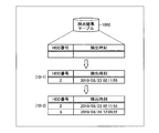
- the detected detection result may be stored in, for example, the detection result table 1000 shown in FIG.
- the detection result table 1000 is realized by the memory 307, for example.
- the detection result table 1000 will be described.
- FIG. 10 is an explanatory diagram showing a specific example of the detection result table 1000.
- the detection result table 1000 has fields of HDD number and detection time, and the detection result is stored as a record by setting information in each field.
- the HDD number is an identifier of the HDD in which a failure has occurred.
- the detection time is the time when the failed HDD is detected.
- (10-1) in FIG. 10 is an update example of the detection result table 1000 when the HDD 2 is detected as the failed HDD.
- the detection unit 507 writes the HDD number “2” of the HDD 2 in the HDD number field of the detection result table 1000.
- the detection unit 507 writes the detection time “2010/08/23 02:11:55” at which the HDD 2 is detected in the detection time field of the detection result table 1000.
- the detection unit 507 writes the HDD number “3” of the HDD 3 in the HDD number field of the detection result table 1000.
- the detection unit 507 writes the detection time “2010/08/24 12:09:22” at which the HDD 3 was detected in the detection time field of the detection result table 1000.
- the determination unit 508 determines whether or not the storage system 300 needs to be down.
- the determination unit 508 has a function of determining whether or not the number of failed HDDs x is equal to or greater than a predetermined number X based on the detected detection result.
- the predetermined number X is set to a value at which the storage system 300 enters a multi-dead state when the number of failed HDDs is X or more.
- the determination unit 508 refers to the management data 410, 420, 430 of each HDD1 to HDD3 via the HDD controller 309, and the status of the HDD1 to HDD3 becomes “abnormal”.
- the numbers x1, x2, and x3 of the HDDs are specified.
- the determination unit 508 specifies the maximum value among the numbers x1, x2, and x3 as the number x of HDDs in which a failure has occurred.
- the determination unit 508 specifies the maximum value among the numbers x1, x2, and x3 as the number x of HDDs in which a failure has occurred.
- the determination unit 508 when the number x of failed HDDs is equal to or greater than the predetermined number X, the determination unit 508 notifies the CPU 301 that the number x of failed HDDs is equal to or greater than the predetermined number X. That is, since the storage system 300 is in a multi-dead state, the determination unit 508 requests the CPU 301 to bring the storage system 300 down.
- the CPU 301 When the CPU 301 is notified that the number x of the failed HDDs is equal to or greater than the predetermined number X, the CPU 301 brings the storage system 300 down. That is, the CPU 301 brings down the storage system 300 because the storage system 300 is in a multi-dead state.
- the storage system 300 when the storage system 300 that has been down is restored, for example, the storage system 300 is returned to the non-redundant configuration immediately before the system down. Specifically, for example, first, a hard reset (or power OFF / ON) of the storage system 300 is performed by an operation input by the CPU 301 or the user.
- the processor 306 identifies the order in which the failure occurred for the plurality of failed HDDs. Specific processing contents for specifying the order of the failed HDDs will be described later. Thereafter, the processor 306 takes the HDDs other than the HDD in which the failure occurred last out of the plurality of failed HDDs offline. In other words, the processor 306 brings only the HDD in which the failure has occurred last out of the plurality of HDDs in which the failure has occurred.
- the processor 306 updates the status of the HDD in which the failure has occurred last in the management data 410, 420, 430 of each HDD1 to HDD3 via the HDD controller 309.
- the management data to be updated is the management data of the HDD that is online.
- the processor 306 changes the status of the HDD 3 in the management data 410 and 430 of the online HDD 1 and HDD 3 from “abnormal” to “normal”.
- the storage system 300 is restarted by an operation input from the CPU 301 or the user.
- the CPU 301 may output a startup notification of the storage system 300 to the processor 306.
- the storage system 300 can be returned to the non-redundant configuration immediately before the system is down.
- the storage system 300 is restarted by an operation input by the CPU 301 or the user, but the processor 306 may restart the storage system 300.
- the determination unit 508 has a function of determining whether or not the HDD for which the write process for the write request has been executed has been restarted.
- the HDDs on which the writing process for the writing request has been executed are, for example, the HDD 1 and the HDD 3 in the case of the writing processes (A) and (B).
- the HDD that has executed the writing process for the writing request is the HDD 3.
- the determination unit 508 when the determination unit 508 receives a startup notification of the storage system 300 from the CPU 301, it determines that the HDD on which the write process for the write request has been executed has been restarted. Further, when the determination unit 508 receives a startup completion notification from the HDD in which the write process for the write request has been executed, the determination unit 508 determines that the HDD in which the write process for the write request has been executed has been restarted. Also good.
- the write instruction unit 509 sends the data Di copied to the write buffer B to the HDD controller 309 as the copy source. It has a function to instruct to write to the LBA.
- the copy source LBA of the data Di is the LBAj of the HDDk that is the request destination of the write request.
- the write instruction unit 509 sends the parity data Pj copied to the write buffer B to the HDD controller 309. It has a function of instructing to write to the LBA of the copy source.
- the copy source LBA of the parity data Pj is the storage destination LBAj of the parity data Pj whose generation source is the data Di stored in the LBAj of the request destination HDDk.
- the write instruction unit 509 instructs the HDD controller 309 to write the data D1 copied to the write buffer B1 to the LBA1 of the HDD1.
- the HDD controller 309 reads out the data D1 stored in the write buffer B1 and writes it in LBA1 of the HDD1.
- the HDD controller 309 reads the data D1 from any accessible write buffer B1 among the write buffers B1 of the HDD1 to HDD3.
- the data D1 is written back to the LBA1 that is the copy source of the HDD1.
- the write instruction unit 509 instructs the HDD controller 309 to write the parity data P1 copied to the write buffer B2 to the LBA1 of the HDD3.
- the HDD controller 309 reads out the parity data P1 stored in the write buffer B2 and writes it in the LBA1 of the HDD3.
- the HDD controller 309 reads the parity data P1 from any accessible write buffer B2 among the write buffers B2 of the HDD1 to HDD3.
- the parity data P1 is written back to the copy source LBA1 of the HDD 3.
- data consistency between the HDD 1 and the HDD 3 can be achieved.
- the write instruction unit 509 sends the plurality of parity data copied to the write buffer B to the copy source LBA to the HDD controller 309. Instruct each to write.
- the copy instruction unit 504 instructs the HDD controller 309 to write the two types of parity data copied to the write buffer B to the copy source LBA.
- FIG. 11 is an explanatory diagram (part 1) showing a transition example of the stored contents of LBA1 of HDD1 to HDD3.
- (11-1) of FIG. 11 as a result of the execution of the write process for the write request 600, the write data D1 # for the LBA1 of the HDD1 has been successfully written, and the new parity data P1 # for the LBA1 of the HDD3 Writing has failed.
- the storage content of the LBA1 of the HDD 3 is the parity data Px different from the parity data P1 #.
- the HDD 3 is detected as a failed HDD and goes offline. For this reason, the storage system 300 enters a multi-dead state and the system goes down.
- the data D1 copied to the write buffer B1 is written to the LBA1 of the HDD1, and the parity data P1 copied to the write buffer B2 is written to the LBA1 of the HDD3.
- the parity data P1 copied to the write buffer B2 is written to the LBA1 of the HDD3.
- the storage system 300 may be turned off / on due to an instantaneous power failure or the like. For this reason, after the writing process in response to the writing request is normally completed, the storage system 300 may be turned OFF / ON due to an instantaneous power failure and the storage system 300 may be restarted. In this case, when the data Di and the parity data Pj copied to the write buffer B are written to the copy source LBA after restarting, the storage content of the copy source LBA is written to the write request. It will return to the previous state.
- the write instruction unit 509 is copied to the write buffer B when the success / failure determination unit 506 determines that the writing process has failed and the determination unit 508 determines that the HDD has been restarted.
- Data Di may be written in the LBA of the copy source.
- the write instruction unit 509 is copied to the write buffer B when the success / failure determination unit 506 determines that the writing process has failed and the determination unit 508 determines that the HDD has been restarted.
- the parity data Pj may be written to the LBA of the copy source.
- the write instruction unit 509 first determines whether or not the write state flag of the write state table 700 shown in FIG. 7 is “0”.
- the write state flag is “0”
- the writing process is not being performed, so that the write instruction unit 509 determines that the HDD has been restarted by the determination unit 508.
- the data Di and the parity data Pj copied to the write buffer B are not written to the copy source LBA.
- the write instruction unit 509 writes the data Di and parity data Pj copied to the write buffer B to the LBA that is the copy source.
- the data Di and parity data Pj copied to the write buffer B are copied from the copy source. Writing back to the LBA can be prevented.
- the write of the write data D1 # to the HDD 1 fails, and the write of the parity data P1 # to the HDD 3 fails, and the storage system 300 is multi-dead. It may be in a state. In this case, when the storage system 300 that has gone down is restored, the storage system 300 may be returned from the multi-dead state to the redundant configuration.
- a hard reset of the storage system 300 that has gone down is performed by an operation input by the CPU 301 or the user.
- the storage system 300 is restarted by an operation input from the CPU 301 or the user.
- both the HDD 1 and the HDD 3 in which the failure has occurred are brought online. Thereby, the storage system 300 can be returned to the redundant configuration.
- the write instruction unit 509 stores the write buffer B in the write buffer B via the HDD controller 309 at the start of the write process.
- the copied data Di is written in the copy source LBA. If the write instruction unit 509 determines that the HDD for which the write process for the write request has been executed has been restarted, the write instruction unit 509 receives the parity data Pj copied to the write buffer B via the HDD controller 309. Write to the LBA of the copy source.
- FIG. 12 is an explanatory diagram (part 2) showing a transition example of the stored contents of LBA1 of HDD1 to HDD3.
- (12-1) of FIG. 12 as a result of the execution of the write process for the write request 600, writing of the write data D1 # to LBA1 of HDD1 failed, and at the same time, writing of parity data P1 # to LBA1 of HDD3 Has failed.
- the storage content of the LBA1 of the HDD1 is data Dx different from the write data D1 #.
- the storage content of the LBA1 of the HDD 3 is the parity data Px different from the parity data P1 #.
- HDD1 and HDD3 are detected as failed HDDs and go offline. For this reason, the storage system 300 enters a multi-dead state and the system goes down.
- the system can be operated even if writing of data Di to the requested HDDk or parity data Pj to the parity drive fails and a non-redundant configuration is obtained. . For this reason, even if the storage system 300 changes from the redundant configuration to the non-redundant configuration as a result of the execution of the write process for the write request, the update unit 502 sets the write status flag of the write status table 700 to “1”. Change from “0” to “0”.
- the object determination unit 510 has a function of determining whether a failure has occurred in the HDDk that is the request destination of the write request based on the detected detection result. Specifically, for example, the target determination unit 510 refers to the management data 410, 420, 430 of each HDD1 to HDD3 via the HDD controller 309, and the status of the requested HDDk becomes “abnormal”. It is determined whether or not.
- the target determination unit 510 determines that no failure has occurred in the HDDk.
- the target determination unit 510 may determine whether or not a failure has occurred in the request destination HDDk with reference to the detection result table 1000 shown in FIG. Specifically, for example, it is determined whether or not there is a record corresponding to the HDD number included in the write request in the detection result table 1000.
- the target determination unit 510 determines that a failure has occurred in the requested HDDk.
- the target determining unit 510 determines that no failure has occurred in the requested HDDk.
- the copy instruction unit 504 uses the HDD controller 309 to generate parity data having the data Di stored in the LBAj of the requested HDDk as a generation source. Pj is copied to the write buffer B. If it is determined that a failure has occurred in the requested HDDk, the copy instruction unit 504 does not copy the data Di stored in the LBAj of the requested HDDk to the write buffer B.
- the determination unit 508 determines whether or not the HDD in which the write process for the write request is executed has been restarted. For example, when it is determined that the HDD in which the write process for the write request has been executed has been restarted, the write instruction unit 509 uses the HDD controller 309 to copy the parity data copied to the write buffer B. Write Pj to the LBAj of the copy source.
- the target determination unit 510 Based on the detected detection result, the target determination unit 510 generates a failure in the HDD that is the storage destination of the parity data Pj that is generated from the data Di that is stored in the LBAj of the HDDk that is the request destination of the write request. It has a function to determine whether or not. Specifically, for example, the target determination unit 510 refers to the management data 410, 420, 430 of each HDD1 to HDD3 via the HDD controller 309, and the status of the parity drive (HDD3) becomes “abnormal”. It is determined whether or not.
- the target determination unit 510 determines that no failure has occurred in the parity drive.
- the target determination unit 510 may determine whether or not a failure has occurred in the parity drive with reference to the detection result table 1000 shown in FIG. Specifically, for example, it is determined whether or not there is a record in the detection result table 1000 corresponding to the HDD number “3” of the HDD 3 that is the parity drive.
- the target determining unit 510 determines that a failure has occurred in the parity drive.
- the target determination unit 510 determines that no failure has occurred in the parity drive.
- the copy instruction unit 504 copies the data Di stored in the LBAj of the requested HDDk to the write buffer B via the HDD controller 309. If the copy instruction unit 504 determines that a failure has occurred in the parity drive, the copy instruction unit 504 sends the data Di stored in the LBAj of the requesting HDDk to the write buffer B of the parity data Pj that is generated. Is not copied.
- the determination unit 508 determines whether or not the HDD in which the write process for the write request is executed after the data Di is copied to the write buffer B is restarted. Then, for example, when it is determined that the HDD for which the write process for the write request has been executed has been restarted, the write instruction unit 509 receives the data Di copied to the write buffer B via the HDD controller 309. Is written to LBAj of the requesting HDDk.
- the copy instruction unit 504 may copy the write data Di # included in the write request to the write buffer B via the HDD controller 309. For example, when the write request 600 is received, the copy instruction unit 504 copies the data D1 stored in the LBA1 of the HDD1 to the write buffer B1 of each of the HDD1 to HDD3 via the HDD controller 309. Further, the copy instruction unit 504 copies the parity data P1 having the data D1 stored in the LBA1 of the HDD1 to the write buffer B2 of each of the HDD1 to HDD3 via the HDD controller 309. Further, the copy instruction unit 504 copies the write data D1 # included in the write request 600 to the write buffer B3 (see FIG. 8) of each HDD1 to HDD3 via the HDD controller 309.
- determination unit 508 determines whether or not the HDD in which the write process for the write request is executed after data Di, parity data Pj, and write data Di # are copied to write buffer B is restarted. Judging. For example, after the determination unit 508 copies the data D1, the parity data P1, and the write data D1 # to the write buffers B1 to B3, the HDD in which the write process for the write request 600 has been executed is restarted. It is determined whether or not.
- the write instruction unit 509 When it is determined that the HDD has been restarted, the write instruction unit 509 writes the data Di copied to the write buffer B to the requested LBAj via the HDD controller 309. Further, the write instruction unit 509 writes the parity data Pj copied to the write buffer B to the copy source LBAj via the HDD controller 309.
- the write instruction unit 509 writes the write data Di # copied to the write buffer B into the requested LBAj via the HDD controller 309. Further, the write instruction unit 509 writes the parity data Pj #, which is generated from the write data Di #, to the LBAj, which is the copy source of the parity data Pj, via the HDD controller 309.
- the write instruction unit 509 transmits the data D1 copied to the write buffer B1 via the HDD controller 309. Write to LBA1 of the requested HDD1.
- the write instruction unit 509 writes the parity data P1 copied to the write buffer B2 to the LBA1 of the copy source HDD 3 via the HDD controller 309.
- the write instruction unit 509 calculates parity data P1 # using the write data D1 # copied to the write buffer B3 as a generation source via the HDD controller 309. Then, the write instruction unit 509 writes the write data D1 # copied to the write buffer B3 to the LBA1 of the requesting HDD 1 via the HDD controller 309. Also, the write instruction unit 509 writes the calculated parity data P1 # to the LBA1 of the HDD 3 that is the copy source of the parity data P1 via the HDD controller 309.
- the data Di copied to the write buffer B and the parity data Pj are written back to ensure data consistency between the HDDs after restart, and then the write data Di # copied to the write buffer B is used.
- the write process for the write request can be re-executed.
- the updating unit 502 sets the writing state flag in the writing state table 700. Change from “1” to “0”. That is, for example, data consistency between HDDs is ensured by writing back data Di and parity data Pj copied to write buffer B to LBAj of the copy source. The status flag is changed from “1” to “0”.
- the update unit 502 may initialize the write buffer B when the write status flag of the write status table 700 is changed from “1” to “0”. That is, when the writing process or the data writing process for the write request is successful, the update unit 502 discards the data Di, the parity data Pj, and the write data Di # copied to the write buffers B1 to B3.
- the data Di copied to the write buffer B may be used as read data when reading the data Di. . If the data write process fails, the parity data Pj copied to the write buffer B may be used as read data when reading the parity data Pj. If the data writing process fails, the write data Di # copied to the write buffer B may be used as the read data when the write data Di # is read. Thereby, the storage system 300 can be normally operated until a new write request is accepted.
- the copy instruction unit 504 When it is determined that the number of failed HDDs x is less than the number Y of parity drives, the copy instruction unit 504 writes the write data Di # included in the write request via the HDD controller 309. Copy to buffer B. Further, when it is determined that the number of failed HDDs x is less than the number Y of parity drives, the copy instruction unit 504 does not copy the data Di and the parity data Pj to the write buffer B.
- determination unit 508 determines whether or not the HDD in which the write process for the write request is executed after the write data Di # included in the write request is copied to write buffer B is restarted. to decide.
- the write instruction unit 509 writes the write data Di # copied to the write buffer B to the request destination LBAj via the HDD controller 309. Further, the write instruction unit 509 writes the parity data Pj #, which is generated from the write data Di #, to the LBAj, which is the copy source of the parity data Pj, via the HDD controller 309.
- FIG. 13 is an explanatory diagram (part 3) showing a transition example of the stored contents of LBA1 of HDD1 to HDD3.
- (13-1) of FIG. 13 as a result of the execution of the write process for the write request 600, writing of the write data D1 # to LBA1 of HDD1 fails, and writing of parity data P1 # to LBA1 of HDD3 is failed. It has failed. In this case, HDD1 and HDD3 are detected as failed HDDs and go offline. For this reason, the storage system 300 enters a multi-dead state and the system goes down.
- the write data D1 # copied to the write buffer B3 is written to the LBA1 of the HDD1.
- the copy instruction unit 504 copies the write data Di # included in the write request to the write buffer B via the HDD controller 309 when it is determined that a failure has occurred in the requested HDDk. To do. If it is determined that a failure has occurred in the requested HDDk, the copy instruction unit 504 does not copy the data Di and the parity data Pj to the write buffer B.
- determination unit 508 determines whether or not the HDD in which the write process for the write request is executed after the write data Di # included in the write request is copied to write buffer B is restarted. to decide.
- the write instruction unit 509 converts the parity data Pj #, which is generated from the write data Di #, to the copy source of the parity data Pj via the HDD controller 309. Write to LBAj.
- a transition example of the storage contents of LBA1 of HDD1 to HDD3 when the request destination HDDk accepts an offline write request will be described.
- a write process (above (C)) for a write request for updating data D2 of LBA1 of HDD2 to write data D2 # is executed in a non-redundant configuration in which HDD2 is offline. Will be described.
- FIG. 14 is an explanatory diagram (part 4) showing a transition example of the storage contents of the LBA 1 of the HDD 1 to HDD 3.
- (14-1) of FIG. 14 as a result of the execution of the write process for the write request for updating the data D2 of LBA1 of HDD2 to data D2 #, writing of parity data P1 # to LBA1 of HDD3 failed. Yes.
- the HDD 3 is detected as a failed HDD and goes offline. For this reason, the storage system 300 enters a multi-dead state and the system goes down.
- data consistency is ensured between HDD1 and HDD3, and thereafter, it becomes possible to restore the write data D2 # of LBA1 of HDD2 that is offline.
- the copy instruction unit 504 copies the write data Di # included in the write request to the write buffer B via the HDD controller 309.
- the copy instruction unit 504 does not copy the data Di and the parity data Pj to the write buffer B.
- determination unit 508 determines whether or not the HDD in which the write process for the write request is executed after the write data Di # included in the write request is copied to write buffer B is restarted. to decide.
- the write instruction unit 509 writes the write data Di # copied to the write buffer B to the request destination LBAj via the HDD controller 309. As a result, it is possible to reduce the copying process of the data Di to the write buffer B and the data writing process to the copy source LBAj of the data Di copied to the write buffer B.
- FIG. 15 is an explanatory diagram (part 5) showing a transition example of the storage contents of the LBA 1 of the HDD 1 to HDD 3.
- (15-1) of FIG. 15 as a result of the execution of the write process for the write request 600, writing of the write data D1 # to the LBA1 of the HDD 1 has failed. In this case, the HDD 1 is detected as a failed HDD and goes offline. For this reason, the storage system 300 enters a multi-dead state and the system goes down.
- the write buffer B is provided in each of the system areas 314, 315, and 316 of the HDD1 to HDD3 has been described as an example, but may be provided in the nonvolatile memory 308.
- the copy instruction unit 504 and the write instruction unit 509 can directly access the write buffer B without going through the HDD controller 309. Further, in order for the copy instruction unit 504 to copy the data Di, parity data Pj, and the like to the write buffer B, it is not necessary to access the plurality of HDD1 to HDD3.
- the write buffer B when the write buffer B is provided in the nonvolatile memory 308, the data copy processing by the copy instruction unit 504 and the data writing by the write instruction unit 509 are compared to the case where the write buffer B is provided in each of the HDD1 to HDD3. Processing speed can be increased.
- the write buffer B when the write buffer B is provided in the system areas 314, 315, and 316 of the HDD1 to HDD3, the amount of data stored in the nonvolatile memory 308 can be suppressed.
- the processor 306 refers to the management data 410, 420, 430 of each HDD1 to HDD3 via the HDD controller 309. Then, the processor 306 identifies the HDD 2 and HDD 3 whose status is “abnormal” in at least one of the management data 410, 420, and 430.
- the processor 306 refers to the access log of the management data 420 of the identified HDD 2 via the HDD controller 309, and identifies the access time (hereinafter referred to as “access time t1”) when the HDD 2 was last accessed. To do. Also, the processor 306 refers to the access log of the management data 430 of the specified HDD 3 via the HDD controller 309, and specifies the last access time (hereinafter referred to as “access time t2”) to the HDD 3. .
- the processor 306 compares the identified access time t1 with the access time t2, and identifies the order in which the failure has occurred for the HDD2 and HDD3. Specifically, for example, the processor 306 specifies that failures have occurred in HDD 2 and HDD 3 in the order of access time.
- the processor 306 specifies that a failure has occurred in the HDD 3 after a failure has occurred in the HDD 2.
- the order in which failures occur is specified from the access logs of the management data 410, 420, 430 as an example, the order in which failures occur is specified from the start times of the HDD1 to HDD3. Also good. Specifically, for example, the processor 306 may specify that a failure has occurred in HDD 2 and HDD 3 in descending order of activation time.
- the management data 410, 420, 430 of each HDD1 to HDD3 may not be updated properly due to a failure of the HDD.
- the processor 306 may refer to the detection result table 1000 to specify the order in which the failure has occurred for a plurality of failed HDDs.
- the processor 306 refers to the HDD number in the detection result table 1000 and identifies the HDD 2 and HDD 3 in which a failure has occurred. Then, the processor 306 refers to the detection time in the detection result table 1000 and identifies the order in which the failure has occurred for the plurality of HDDs 2 and 3 in which the failure has occurred.
- the processor 306 specifies that a failure has occurred in HDD 2 and HDD 3 in the order of detection time.
- the detection time “2010/08/23 02:11:55” of the HDD 2 is older than the detection time “2010/08/24 12:09:22” of the HDD 3. Therefore, the processor 306 specifies that a failure has occurred in the HDD 3 after a failure has occurred in the HDD 2.
- FIGS. 16 and 17 are flowcharts illustrating an example of a data copy processing procedure of the storage control device according to the first embodiment.
- the accepting unit 501 determines whether or not a write request for the LBAj of the HDDk has been accepted (step S1601).
- step S1602 changes the write state flag of the write state table 700 from “0” to “1” (step S1603). Further, the update unit 502 writes the HDD number “k” and the LBA number “j” included in the accepted write request into the write state table 700 (step S1604).
- the copy instruction unit 504 copies the write data Di # included in the write request via the HDD controller 309 to the write buffer B3 of each HDD1 to HDD3 (step S1605). Thereafter, the execution unit 505 executes write processing for the accepted write request (step S1606), and the process proceeds to step S1701 shown in FIG.
- step S1602 when the number x of the failed HDDs is “x ⁇ 0” (step S1602: No), the update unit 502 determines whether the write status flag in the write status table 700 is “1”. Is determined (step S1607).
- step S1607: No the update unit 502 changes the write status flag in the write status table 700 from “0” to “1” (step S1608). Further, the update unit 502 writes the HDD number “k” and the LBA number “j” included in the accepted write request into the write state table 700 (step S1609).
- the target determination unit 510 determines whether or not a failure has occurred in the parity drive (step S1610). If a failure has occurred in the parity drive (step S1610: Yes), the process proceeds to step S1605.
- step S1610 determines whether a failure has occurred in the parity drive (step S1611). If a failure has occurred in the HDDk that is the request destination of the write request (step S1611: YES), the process proceeds to step S1605.
- step S1611 if no failure has occurred in the HDDk that is the request destination of the write request (step S1611: No), the process proceeds to step S1612. Then, the copy instruction unit 504 copies the data Di stored in the LBAj of the HDDk that is the request destination of the write request to the write buffer B1 of each HDD1 to HDD3 via the HDD controller 309 (step S1612). .
- the copy instruction unit 504 copies the parity data Pj generated from the data Di copied to the write buffer B1 to the write buffer B2 of each of the HDD1 to HDD3 via the HDD controller 309 (step S1613). ). Further, the copy instruction unit 504 copies the write data Di # included in the write request to the write buffer B3 of each of the HDD1 to HDD3 (step S1614), and proceeds to step S1606.
- step S1607 when the writing state flag is “1” (step S1607: Yes), the process proceeds to step S1615. Then, the detection unit 507 changes the status of the HDD in which the management data 410, 420, 430 of the online HDD1 to HDD3 failed to be written from “normal” to “abnormal” via the HDD controller 309 (step S1615). ).
- the HDD that failed to be written is identified from, for example, the HDD number set in the field of the write failure HDD number in the write status table 700.
- the detecting unit 507 takes the HDD that failed to be written offline (step S1616). Then, the determination unit 508 notifies the CPU 301 that the number of failed HDDs has become two or more, so that the storage system 300 goes down (step S1617), and a series of processing according to this flowchart is performed. finish.
- step S1607 the writing status flag becomes “1” (step S1607: Yes) when the data writing process fails in step S1804 shown in FIG. 18 described later (step S1804: No). is there.
- the success / failure determination unit 506 determines whether or not the writing process for the write request executed in step S1606 shown in FIG. 16 has succeeded (step S1701). If the write process for the write request is successful (step S1701: Yes), the update unit 502 changes the write status flag of the write status table 700 from “1” to “0” (step S1701). S1702), the process proceeds to step S1704.
- step S1701 determines whether or not a failed HDD has been detected.
- step S1704 when the failed HDD is not detected (step S1704: No), a series of processing according to this flowchart is terminated.
- step S1704: YES if a failed HDD is detected (step S1704: YES), the process proceeds to step S1705. Then, the detection unit 507 changes the status of the failed HDD in the management data 410, 420, 430 of the online HDD1 to HDD3 from “normal” to “abnormal” via the HDD controller 309 (step S1705). ).
- the detecting unit 507 takes the failed HDD offline via the HDD controller 309 (step S1706). Then, the determination unit 508 determines whether or not the number x of the failed HDDs is “x ⁇ 2” (step S1707). If “x ⁇ 2” (step S1707: NO), the update unit 502 changes the write state flag of the write state table 700 from “1” to “0” (step S1708). A series of processes according to the flowchart ends.
- step S1707 Yes
- the process proceeds to step S1709.
- the determination unit 508 notifies the CPU 301 that the number of failed HDDs has become two or more, so that the storage system 300 goes down (step S1709), and a series of processing according to this flowchart is performed. finish.
- the data Di, the parity data Pj, and the write data Di # before the update can be saved in the write buffer B when the data Di accompanying the update of the parity data Pj is updated.
- the write data Di # can be saved in the write buffer B.
- the request destination HDDk or parity drive is offline, only the write data Di # can be saved in the write buffer B.
- FIG. 18 is a flowchart of an example of a system restoration processing procedure of the storage control apparatus 101 according to the first embodiment.
- the determination unit 508 determines whether or not the HDD for which the write process for the write request has been executed has been restarted (step S1801).
- step S1801: No after waiting for the HDD to be restarted (step S1801: No), when the HDD is restarted (step S1801: Yes), the write instruction unit 509 sets the write state flag in the write state table 700. It is determined whether or not “1” (step S1802). If the write state flag is “0” (step S1802: No), the series of processes according to this flowchart is terminated.
- step S1802 when the write state flag is “1” (step S1802: Yes), the write instruction unit 509 executes data write processing (step S1803). A specific processing procedure of the data writing process will be described later. Thereafter, the success / failure determination unit 506 determines whether or not the data writing process is successful (step S1804).
- step S1804 If the data writing process is successful (step S1804: YES), the update unit 502 changes the writing state flag of the writing state table 700 from “1” to “0” (step S1805). A series of processing by this flowchart is complete
- step S1803 differs depending on the step through which the writing process in step S1606 shown in FIG.
- step S1611: No a specific processing procedure of the data writing process when going through
- FIG. 19 is a flowchart showing an example of a specific processing procedure of the data writing processing in step S1803.
- the write instruction unit 509 writes the data Di copied to the write buffer B1 to the requested LBAj via the HDD controller 309 (step S1901).
- the write instruction unit 509 writes the parity data Pj copied to the write buffer B2 to the copy source LBAj via the HDD controller 309 (step S1902). Thereafter, the write instruction unit 509 calculates parity data Pj # using the write data Di # copied to the write buffer B3 as a generation source via the HDD controller 309 (step S1903).
- the write instruction unit 509 writes the write data Di # copied to the write buffer B3 to the requested LBAj via the HDD controller 309 (step S1904). Then, the write instruction unit 509 writes the calculated parity data Pj # into the LBAj that is the copy source of the parity data Pj via the HDD controller 309 (step S1905), and the process proceeds to step S1804 shown in FIG. To do.
- the data Di and the parity data Pj saved in the write buffer B are written back to the save source to ensure data consistency between the HDDs after restart, and then the write data Di saved in the write buffer B Using #, the write process for the write request can be re-executed.
- step S1804 If the data writing process in step S1804 fails, data Di, parity data Pj and write data Di # saved in write buffer B are read data until a new write request is accepted. Can be used. If the data write process in step S1804 fails, a message indicating that the write process for the write request failed even if the HDD is restarted is displayed on the display 304 shown in FIG. You may decide to notify. Note that after the above-described system recovery process is performed, the storage system 300 may be returned to the redundant configuration by replacing the failed HDD and performing a rebuild.
- the data Di stored in the LBAj of the request destination HDDk is copied to the write buffer B before the execution of the write process for the write request. be able to.
- the parity data Pj having the data Di as the generation source can be copied to the write buffer B before the execution of the write process for the write request.
- the data Di and the parity data Pj before the update can be saved in the write buffer B when the data Di accompanying the update of the parity data Pj is updated.
- the storage control device 101 when the HDD in which the write process for the write request is executed is restarted, the data Di copied to the write buffer B is written to the LBAj of the request destination HDDk. it can. Further, according to the storage control apparatus 101, when the HDD for which the write process for the write request has been executed is restarted, the parity data Pj copied to the write buffer B can be written to the copy source LBAj. . As a result, even if writing to the HDD fails due to a failure such as thermal off-track, the data Di and parity data Pj saved in the write buffer B are written back to the saving source LBAj after the HDD is restarted. Data consistency can be taken between.
- the storage control device 101 when the write process for the write request fails and the HDD on which the write process is executed is restarted, the data Di and the parity copied to the write buffer B are restored. Data Pj can be written to the LBAj of the copy source. As a result, even if the HDD is restarted due to a momentary power failure or the like after the write process for the write request is successful, the data Di and the parity data Pj saved in the write buffer B are written in the save source LBAj. It can be prevented from returning.
- the write data Di # included in the write request can be copied to the write buffer B before the execution of the write process for the write request. Further, according to the storage controller 101, the data Di and the parity data Pj copied to the write buffer B are written back to the copy source LBAj, and then the write data Di # copied to the write buffer B is used. The write process for the write request can be re-executed. As a result, after the data Di and the parity data Pj are written back to the save source to ensure data consistency between the HDDs after the restart, the write process for the write request can be re-executed.
- the storage control device 101 when the requested HDDk is offline, the write data Di # is copied to the write buffer B, and after the HDD is restarted due to a write failure, the copied write data Di # is copied. Can be used to re-execute the writing process for the write request.
- the storage control device 101 when the parity drive is offline, the write data Di # is copied to the write buffer B, and after the HDD is restarted due to a write failure, the copied write data Di # is used. Thus, the write process for the write request can be re-executed.
- the storage control device 101 when a write request is accepted in a redundant configuration, the write data Di # is copied to the write buffer B, and the copied write data is copied after the HDD is restarted due to a write failure. Di # can be used to re-execute the write process for the write request.
- the storage control apparatus 101 it is possible to ensure data consistency between HDDs when the storage system is restored. As a result, data corruption of read data caused by data inconsistency between HDDs due to write failure can be prevented, and the system can be prevented from starting or malfunctioning.
- the storage control apparatus 101 includes the control unit 503.
- each HDD1 to HDD3 may include the control unit 503.
- the control unit 503 of each of the HDD1 to HDD3 controls access to each of the HDD1 to HDD3 in accordance with, for example, instructions from the copy instruction unit 504, the execution unit 505, and the write instruction unit 509 of the storage control apparatus 101.
- the storage control apparatus 101 is applied to a RAID 5 storage system 2000.
- RAID5 is a method in which each data of a data group is distributed and recorded on a plurality of HDDs, and parity data generated from the data group is distributed and recorded on a plurality of HDDs.
- the RAID 5 storage system 2000 does not record parity data on a dedicated HDD (parity drive) as in the RAID 3 storage system, but distributes and records parity data on a plurality of HDDs.
- symbol is attached
- FIG. 20 is a block diagram of a hardware configuration of the storage system 2000 according to the second embodiment.
- the storage system 2000 includes a CPU 301, a main memory 302, a display controller 303, a display 304, a communication controller 305, a storage control device 101, and HDD1 to HDD3.
- the storage control apparatus 101 includes a processor 306, a memory 307, a nonvolatile memory 308, an HDD controller 309, and a bus controller 310.
- the strip is a storage area in which a plurality of blocks of the hard disk are bundled.
- a block is a storage area in which a plurality of sectors divided from a track in which a hard disk is concentrically divided is bundled.
- the data area 311 of the HDD 1 includes a strip A, a strip C, and a strip P3.
- the data area 312 of the HDD 2 includes a strip B, a strip P2, and a strip E.
- the data area 313 of the HDD 3 includes a strip P1, a strip D, and a strip F.
- data a0 is stored in strip A of HDD1.
- Data b0 is stored in the strip B of the HDD 2.
- the strip P1 of the HDD 3 stores parity data p1 obtained by exclusive OR of the data a0 of the strip A and the data b0 of the strip B.
- Data c0 is stored in the strip C of the HDD1.
- Data d0 is stored in the strip D of the HDD 3.
- the strip P2 of the HDD 2 stores parity data p2 obtained by exclusive OR of the data c0 of the strip C and the data d0 of the strip D.
- Data e0 is stored in strip E of HDD2.
- Data f0 is stored in the strip F of the HDD 3.
- the strip P3 of the HDD 1 stores parity data p3 obtained by taking an exclusive OR of the data e0 of the strip E and the data f0 of the strip F.
- the write state table 2100 stores write state information for specifying whether or not the write process for the write request has been normally completed. Moreover, the write state table 2100 is realized by the nonvolatile memory 308 shown in FIG. 20, for example.
- FIG. 21 is an explanatory diagram showing a specific example of the writing state table 2100.
- a write state table 2100 has fields for a write state flag and a strip number. By setting information in each field, write state information is stored as a record.
- the write status flag is a flag indicating whether or not the write process for the write request has been normally completed.
- the write state flag is “0” in the initial state, and is changed from “0” to “1” when a write request is accepted.
- the writing status flag is changed from “1” to “0” when the writing process for the writing request is normally completed.
- the strip number is an identifier of a strip to which a write request is requested.
- Storage control processing procedure of the storage control device 101 Next, a storage control processing procedure of the storage control apparatus 101 according to the second embodiment will be described.
- a case will be described as an example where the storage system 2000 is applied to an online system such as a bank and the user deposits / withdraws cash using an ATM (Automated Teller Machine).
- ATM Automatic Teller Machine
- ⁇ Storage control processing procedure for redundant configuration> 22 to 24 are flowcharts showing an example of the storage control processing procedure of the storage control apparatus 101 in the redundant configuration.
- the accepting unit 501 accepts a write request for updating the data b0 of the strip B to the data b1 (step S2201).
- the write request includes the strip number “B” of the requested strip B and the data b1 to be written.
- the data b1 is an event log indicating that the OS has started up.
- the update unit 502 changes the write status flag of the write status table 2100 shown in FIG. 21 from “0” to “1” (step S2202). Further, the updating unit 502 writes the strip number “B” included in the accepted write request in the strip number field of the write state table 2100 (step S2203).
- the copy instruction unit 504 copies the data b1 included in the write request to the write buffer B3 of each HDD1 to HDD3 via the HDD controller 309 (step S2204). Thereafter, the execution unit 505 executes write processing for the accepted write request (step S2205).
- the execution unit 505 writes the data b1 included in the write request to the strip B via the HDD controller 309. Further, the execution unit 505 strips the parity data p1 (# 1) obtained by taking an exclusive OR of the data b1 included in the write request and the data a0 recorded in the strip A via the HDD controller 309. Write to P1.
- the writing process for the writing request is successful.
- the update unit 502 changes the write status flag of the write status table 2100 from “1” to “0” (step S2206).
- the processor 306 reads the data a0 of the strip A and the data b1 of the strip B, starts the operation program (step S2207), and proceeds to step S2301 shown in FIG.
- the receiving unit 501 receives a write request for updating the data c0 of the strip C to the data c1 (step S2301).
- the write request includes the strip number “C” of the requested strip C and the data c1 to be written.
- the data c1 is deposit data of 100,000 yen.
- the update unit 502 changes the write status flag of the write status table 2100 from “0” to “1” (step S2302). Further, the update unit 502 writes the strip number “C” included in the accepted write request in the strip number field of the write state table 2100 (step S2303).
- the copy instruction unit 504 copies the data c1 included in the write request to the write buffer B3 of each HDD1 to HDD3 via the HDD controller 309 (step S2304). Thereafter, the execution unit 505 executes write processing for the accepted write request (step S2305).
- the execution unit 505 writes the data c1 included in the write request to the strip C via the HDD controller 309. Further, the execution unit 505 calculates, via the HDD controller 309, parity data p2 (# 1) obtained by taking an exclusive OR of the data c1 included in the write request and the data d0 recorded in the strip D. And write to the strip P2. Here, it is assumed that the writing process for the writing request is successful.
- the update unit 502 changes the write state flag of the write state table 2100 from “1” to “0” (step S2306), and the process proceeds to step S2401 shown in FIG. As a result, the deposit data of 100,000 yen is recorded on the strip C.
- the receiving unit 501 receives a write request for updating the data d0 of the strip D to the data d1 (step S2401).
- the write request includes the strip number “D” of the requested strip D and the data d1 to be written.
- Data d1 is 5,000 yen withdrawal data.
- the update unit 502 changes the write status flag of the write status table 2100 from “0” to “1” (step S2402). Further, the update unit 502 writes the strip number “D” included in the accepted write request in the strip number field of the write state table 2100 (step S2403).
- the copy instruction unit 504 copies the data d1 included in the write request to the write buffer B3 of each of the HDD1 to HDD3 via the HDD controller 309 (step S2404). Thereafter, the execution unit 505 executes write processing for the accepted write request (step S2405).
- the execution unit 505 writes the data d1 included in the write request to the strip D via the HDD controller 309. Further, the execution unit 505 calculates the parity data p2 (# 2) obtained by taking the exclusive OR of the data d1 included in the write request and the data c1 recorded in the strip C via the HDD controller 309. And write to the strip P2.
- both the case where the write process for the write request succeeds and the case where the write process for the write request fails are assumed.
- failure assume that the storage system 2000 is powered off due to an instantaneous power failure or the like during writing of the data d1 included in the write request for the strip D, and a part of the data d1 cannot be written to the strip D. To do.
- the data stored in the strip D is data dx different from both the data d0 and the data d1.
- the parity data p2 (# 2) stored in the strip P2 is calculated using the data d1. Therefore, at this time, data mismatch occurs between the strip D and the strip P2.
- the determination unit 508 determines whether the HDD has been restarted (step S2406). If the HDD is restarted (step S2406: YES), the write instruction unit 509 writes the data d1 copied to the write buffer B3 to the strip D via the HDD controller 309 (step S2407). .
- the write instruction unit 509 calculates the parity data p2 (# 2) via the HDD controller 309 and writes it to the strip P2 (step S2408).
- Parity data p2 (# 2) is calculated from data d1 copied to write buffer B3 and data c1 stored in strip C.
- the update unit 502 changes the write status flag of the write status table 2100 from “1” to “0” (step S2409), and the series of processing according to this flowchart ends.
- step S2406 No
- the update unit 502 changes the write status flag in the write status table 2100 from “1” to “0” (step S2406).
- step S2409 a series of processing according to this flowchart is terminated.
- the data d1 copied to the write buffer B3 is used after the power is turned on.
- the write process for the load request can be re-executed.
- withdrawal data of 5,000 yen is recorded on the strip D.
- the balance data of 95,000 yen can be referred to from the data c1 of the strip C and the data d1 of the strip D.
- FIG. 25 is an explanatory diagram (part 2) illustrating an example of updating the management data 410, 420, and 430.
- FIG. 25 shows an example of updating the management data 410, 420, 430 of each HDD1 to HDD3 when a failure occurs in the HDD1.
- the upper row shows the management data 410, 420, 430 when the HDD1 to HDD3 are in a normal state
- the lower row is the management data 410, 420, 430 after the failure of the HDD1.
- the status of the HDD 1 in the management data 410 has been updated from “normal” to “(abnormal)”.
- “(abnormal)” indicates that the status of the HDD 1 in the management data 410 becomes “abnormal” when the HDD controller 309 can update the management data 410.
- the status of the HDD 1 in the management data 420 is updated from “normal” to “abnormal”.
- the status of the HDD 1 in the management data 430 is updated from “normal” to “abnormal”.
- FIG. 26 and FIG. 27 are flowcharts showing an example of the storage control processing procedure of the storage control apparatus 101 in the non-redundant configuration (when HDD 1 is abnormal).
- the receiving unit 501 receives a write request for updating the data c1 of the strip C to the data c2 (step S2601).
- the write request includes the strip number “C” of the requested strip C and the data c2 to be written.
- Data c2 is deposit data of 500,000 yen.
- the update unit 502 changes the write state flag of the write state table 2100 from “0” to “1” (step S2602). Further, the update unit 502 writes the strip number “C” included in the received write request into the strip number field of the write state table 2100 corresponding to the write state flag changed to “1” (step S2603). ).
- the copy instruction unit 504 copies the data c2 included in the write request via the HDD controller 309 to the write buffer B3 of each HDD1 to HDD3 (step S2604).
- the execution unit 505 executes write processing for the accepted write request (step S2605).
- the execution unit 505 reads the data d1 from the strip D via the HDD controller 309. Then, the execution unit 505 calculates parity data p2 (# 3) obtained by taking the exclusive OR of the data d1 and the data c2 included in the write request, and writes the calculated parity data p2 (# 3).
- parity data p2 # 3 obtained by taking the exclusive OR of the data d1 and the data c2 included in the write request, and writes the calculated parity data p2 (# 3).
- the update unit 502 changes the write state flag of the write state table 2100 from “1” to “0” (step S2606), and the process proceeds to step S2701 shown in FIG.
- parity data p2 (# 3) reflecting the deposit data of 500,000 yen is written in the strip P2.
- the receiving unit 501 receives a write request for updating the data d1 of the strip D to the data d2 (step S2701).
- the write request includes the strip number “D” of the requested strip D and the data d2 to be written.
- Data d2 is withdrawal data of 100,000 yen.
- the update unit 502 changes the write status flag of the write status table 2100 from “0” to “1” (step S2702). Further, the updating unit 502 writes the strip number “D” included in the accepted write request in the strip number field of the write state table 2100 (step S2703).
- the copy instruction unit 504 copies the data d1 stored in the request destination strip D via the HDD controller 309 to the write buffer B1 of each of the HDD1 to HDD3 (step S2704).
- the write buffer B1 of the HDD 1 cannot be accessed, the data d1 is not copied to the write buffer B1 of the HDD 1.
- the copy instruction unit 504 sends the parity data p2 (# 3) recorded in the strip P2 having the data d1 of the strip D as a generation source via the HDD controller 309 to the write buffer B2 of each HDD1 to HDD3. (Step S2705). However, when the write buffer B2 of the HDD 1 cannot be accessed, the parity data p2 (# 3) is not copied to the write buffer B2 of the HDD 1.
- the copy instruction unit 504 copies the data d2 included in the write request to the write buffer B3 of each HDD1 to HDD3 (step S2706). Similarly to the above, when the write buffer B3 of the HDD 1 cannot be accessed, the data d2 is not copied to the write buffer B3 of the HDD 1. Thereafter, the execution unit 505 executes write processing for the received write request (step S2707).
- the execution unit 505 obtains an exclusive OR of the parity data p2 (# 3) recorded in the strip P2 and the data d1 stored in the strip D, and the data of the strip C Restore c2.
- the execution unit 505 writes the data d2 included in the write request to the strip D via the HDD controller 309.
- the execution unit 505 calculates the parity data p2 (# 4) obtained by taking the exclusive OR of the restored data c2 and the data d2 included in the write request via the HDD controller 309, and strips the data. Write to P2.
- the success / failure determination unit 506 determines whether the writing process for the write request has succeeded (step S2708). If the write process for the write request is successful (step S2708: YES), the update unit 502 changes the write state flag of the write state table 2100 from “1” to “0” (step S2708). S2709), a series of processing according to this flowchart is terminated.
- step S2708 when the write process for the write request has failed (step S2708: No), the detection unit 507 detects the HDD that failed to be written as a failed HDD (step S2710). Then, the detection unit 507 changes the status of the HDD in which the failure of the online HDD management data has occurred from “normal” to “abnormal” via the HDD controller 309 (step S2711).
- the detecting unit 507 takes the failed HDD off-line via the HDD controller 309 (step S2712). Then, the determination unit 508 determines whether or not the number x of the failed HDDs is “x ⁇ 2”. In the example of FIG. 27, it is determined that the number x of HDDs is 2 or more (step S2713). Finally, the determination unit 508 notifies the CPU 301 that the number of failed HDDs has become two or more, and the storage system 2000 goes down (step S2714).
- step S2707 shown in FIG. 27, a failure occurs in HDD 2 and writing of parity data p2 (# 4) to strip P2 fails. Specifically, since a part of the parity data p2 (# 4) could not be written to the strip P2 of the HDD 2, the storage content of the strip P2 is the parity data p2x different from the parity data p2 (# 4). In this case, the HDD 2 is detected as a failed HDD and goes offline.
- FIG. 28 is an explanatory diagram (part 3) illustrating an example of updating the management data 410, 420, and 430.
- FIG. 28 shows an example of updating the management data 410, 420, and 430 of each HDD1 to HDD3 when a failure occurs in the HDD2.
- the upper row shows the management data 410, 420, 430 before the failure of the HDD 2
- the lower row shows the management data 410, 420, 430 after the failure of the HDD 2.
- the status of the HDD 2 in the management data 420 has been updated from “normal” to “(abnormal)”.
- “(abnormal)” indicates that the status of the HDD 2 in the management data 420 becomes “abnormal” when the HDD controller 309 can update the management data 420.
- the status of the HDD 2 in the management data 430 is updated from “normal” to “abnormal”.
- the status of the HDD 2 in the management data 410 remains “normal”.
- FIG. 29 is a flowchart illustrating an example of a system restoration processing procedure of the storage control apparatus 101.
- the determination unit 508 determines whether or not the HDD in which the write process for the write request has been executed, in this example, the HDD 2 has been restarted (step S2901).
- step S2901: No after the HDD 2 is restarted (step S2901: No), when the HDD 2 is restarted (step S2901: Yes), the write state of the write state table 2100 is written by the write instruction unit 509. It is determined whether or not the flag is “1” (step S2902). Here, when the write state flag is “0” (step S2902: No), a series of processing according to this flowchart is ended.
- step S2902 if the write status flag is “1” (step S2902: YES), the write instruction unit 509 writes the data d1 copied to the write buffer B1 to the strip D of the HDD 3 via the HDD controller 309. (Step S2903). Also, the write instruction unit 509 writes the parity data p2 (# 3) copied to the write buffer B2 to the restarted strip P2 of the HDD 2 via the HDD controller 309 (step S2904).
- the write instruction unit 509 writes the data d2 copied in the write buffer B3 to the strip D via the HDD controller 309 (step S2905). Further, the write instruction unit 509 calculates parity data p2 (# 4) having the data d2 as a generation source through the HDD controller 309 and writes it in the strip P2 (step S2906).
- the success / failure determination unit 506 determines whether or not the data writing process in steps S2903 to S2906 is successful (step S2907). If the data writing process is successful (step S2907: YES), the update unit 502 changes the writing state flag of the writing state table 2100 from “1” to “0” (step S2908). A series of processing by this flowchart is complete
- step S2907 NO
- data d1, parity data p2 (# 3), and data d2 copied to write buffers B1 to B3 can be used as read data.
- the data c2 of the strip C can be restored from the data d1 copied to the write buffer B1 and the parity data p2 (# 3) copied to the write buffer B2. .
- the data before updating and the parity data can be saved in the write buffers B1 and B2 when updating the data accompanied by updating the parity data. .
- the storage control device 101 after the HDD is restarted due to a write failure, the data and parity data saved in the write buffers B1 and B2 are written back to the save source strip, and the data consistency between the HDDs Can be taken. Further, according to the storage control device 101, after the data and parity data saved in the write buffers B1 and B2 are written back to the save source strip, the data saved in the write buffer B3 is used to respond to the write request. The writing process can be re-executed.
- the storage control method described in the present embodiment can be realized by executing a program prepared in advance on a computer such as a personal computer or a workstation.
- the storage control program is recorded on a computer-readable recording medium such as a hard disk, a flexible disk, a CD-ROM, an MO, and a DVD, and is executed by being read from the recording medium by the computer.
- the storage control program may be distributed via a network such as the Internet.
- the storage control apparatus 101 described in the present embodiment is a specific application IC (hereinafter simply referred to as “ASIC”) such as a standard cell or a structured ASIC (Application Specific Integrated Circuit), or a PLD (Programmable) such as an FPGA. It can also be realized by Logic Device. Specifically, for example, the storage control apparatus 101 can be manufactured by defining the functions of the storage control apparatus 101 described above by HDL description, and logically synthesizing the HDL description and giving it to the ASIC or PLD.
- ASIC application Integrated Circuit
- PLD Application Specific Integrated Circuit
Landscapes
- Engineering & Computer Science (AREA)
- Theoretical Computer Science (AREA)
- Quality & Reliability (AREA)
- Physics & Mathematics (AREA)
- General Engineering & Computer Science (AREA)
- General Physics & Mathematics (AREA)
- Techniques For Improving Reliability Of Storages (AREA)
Abstract
ストレージ制御装置(101)は、ストレージ装置(S1)に対する書込要求を受け付ける。ストレージ制御装置(101)は、書込要求を受け付けた場合、ストレージ装置(S1)の記憶領域に記憶されているデータ(D1)と、データ(D1)を生成元とするパリティデータ(P)を、特定の記憶領域(200)に複写する。ストレージ制御装置(101)は、書込要求に対する書込処理が実行されたストレージ装置(S1)または(S3)が再起動されたか否かを判断する。ストレージ制御装置(101)は、ストレージ装置(S1)または(S3)が再起動された場合、特定の記憶領域(200)に複写されたデータ(D1)をストレージ装置(S1)の複写元の記憶領域に書き込む。さらに、ストレージ制御装置(101)は、特定の記憶領域(200)に複写されたパリティデータ(P)をストレージ装置(S3)の複写元の記憶領域に書き込む。
Description
本発明は、ストレージ装置を制御するストレージ制御装置およびストレージ制御方法に関する。
RAID(Redundant Array of Inexpensive Disks)3,5等の冗長化されたストレージシステムは、ディスク装置に障害が発生すると、障害が発生したディスク装置を切り離す。ストレージシステムは、障害が発生したディスク装置が切り離されると、切り離されたディスク装置を除く残余のディスク装置によってデータの記録、更新を行う。
また、ストレージシステムは、障害が発生したディスク装置が切り離された後、さらに別のディスク装置に障害が発生すると、新たに障害が発生したディスク装置を切り離す。以下の説明では、ストレージシステム内のディスク装置に障害が発生して冗長化を失った状態から、さらに別のディスク装置を切り離した状態を「マルチデッド状態」という。
ここで、ディスク装置の切り離し要因となる障害としては、例えば、サーマル・オフトラック、コンタミネーション、ノイズ、接触不良等がある。ディスク装置のサーマル・オフトラック、コンタミネーション、ノイズ、接触不良等の障害は、ハードリセットや電源切断後の再投入(電源のOFF/ON)によって回復することが多い。
すなわち、障害が発生して切り離されたディスク装置に対してハードリセットや電源のOFF/ONを行うことで、該ディスク装置を正常に動作するディスク装置として復帰させることができる。このため、マルチデッド状態となったストレージシステムを復旧する場合、例えば、ストレージシステムのハードリセットを行って、マルチデッド状態となる前の状態に戻すことが行われる。
なお、ディスク装置に障害が発生したストレージシステムを復旧するための技術を開示する文献として、例えば、下記特許文献1~3がある。
しかしながら、上述した従来技術では、ストレージシステムの復旧時に、ハードリセット等を行ってストレージシステムをマルチデッド状態となる前の状態に戻しても、ディスク装置間のデータの不整合によりデータ化けが発生する場合があるという問題があった。
本発明は、上述した従来技術による問題点を解消するため、ストレージ装置間のデータの整合性を保障することができるストレージ制御装置およびストレージ制御方法を提供することを目的とする。
上述した課題を解決し、目的を達成するため、開示のストレージ制御装置およびストレージ制御方法は、データ群ごとに、前記データ群の各データと前記データ群から生成される訂正符号とを、記憶先のストレージ装置が異なるように記憶するシステム内のストレージ装置に対する書込要求を受け付け、前記書込要求を受け付けた場合、前記ストレージ装置の要求先の記憶領域に記憶されているデータと、当該データを生成元とする、前記ストレージ装置に記憶されている訂正符号とを、前記ストレージ装置から特定の記憶領域に複写し、前記データと前記訂正符号が前記特定の記憶領域に複写された後、前記書込要求に対する書込処理が実行されたストレージ装置が再起動されたか否かを判断し、ストレージ装置が再起動されたと判断された場合、前記特定の記憶領域に複写されたデータを前記ストレージ装置の要求先の記憶領域に書き込むとともに、前記特定の記憶領域に複写された訂正符号を当該訂正符号の複写元のストレージ装置の記憶領域に書き込む。
上述した課題を解決し、目的を達成するため、開示のストレージ制御装置およびストレージ制御方法は、データ群ごとに、前記データ群の各データと前記データ群から生成される訂正符号とを、記憶先のストレージ装置が異なるように記憶するシステム内のストレージ装置に対する書込要求を受け付け、前記書込要求を受け付けた場合、前記システム内のストレージ装置にアクセスする制御部に対して、前記ストレージ装置の要求先の記憶領域に記憶されているデータと、当該データを生成元とする、前記ストレージ装置に記憶されている訂正符号とを、特定の記憶領域に複写するよう指示し、指示された前記データと前記訂正符号が前記特定の記憶領域に複写された後、前記書込要求に対する書込処理が実行されたストレージ装置が再起動されたか否かを判断し、ストレージ装置が再起動されたと判断された場合、前記制御部に対して、前記特定の記憶領域に複写されたデータを前記ストレージ装置の要求先の記憶領域に書き込むとともに、前記特定の記憶領域に複写された訂正符号を当該訂正符号の複写元のストレージ装置の記憶領域に書き込むよう指示する。
本ストレージ制御装置およびストレージ制御方法によれば、ストレージ装置間のデータの整合性を保障することができるという効果を奏する。
以下に添付図面を参照して、本発明にかかるストレージ制御装置およびストレージ制御方法の好適な実施の形態を詳細に説明する。
(実施の形態1)
図1は、実施の形態1にかかるストレージシステム100の一実施例を示す説明図である。図1において、ストレージシステム100は、ストレージ制御装置101とストレージ装置S1~S3と、を含む構成である。ストレージ制御装置101は、ストレージ装置S1~S3を制御するコンピュータである。ストレージ装置S1~S3は、データを記憶する記憶装置である。ストレージ装置S1~S3は、例えば、ハードディスク、光ディスク、フラッシュメモリ、磁気テープ等の記憶媒体を含む。
図1は、実施の形態1にかかるストレージシステム100の一実施例を示す説明図である。図1において、ストレージシステム100は、ストレージ制御装置101とストレージ装置S1~S3と、を含む構成である。ストレージ制御装置101は、ストレージ装置S1~S3を制御するコンピュータである。ストレージ装置S1~S3は、データを記憶する記憶装置である。ストレージ装置S1~S3は、例えば、ハードディスク、光ディスク、フラッシュメモリ、磁気テープ等の記憶媒体を含む。
ここで、ストレージシステム100は、RAID3,5等の冗長化されたシステムである。ストレージシステム100は、データ群ごとに、データ群の各データと、該データ群の各データから生成される訂正符号とを、記憶先のストレージ装置が異なるように分散して記憶している。データ群は、互いに関連するデータの集合である。各データは、例えば、ビット単位、バイト単位、ブロック(セクタ)単位のデータである。
訂正符号は、データ群を構成するデータを生成元とする冗長コードである。訂正符号としては、生成元のデータ群のいずれかのデータを、データ群の残余のデータと訂正符号とから復元可能なものを用いることができる。具体的には、例えば、訂正符号は、パリティ、ハミング符号、ECC(Error Correcting Code)、CRC(Cyclic Redundancy Check)コード等を用いて実現される。以下の説明では、訂正符号の一例として、生成元のデータ群を構成する各データの排他的論理和をとったパリティデータを例に挙げて説明する。
図1の例では、データD1と、データD2と、データD1,D2から生成されるパリティデータPとが、記憶先のストレージ装置が異なるように分散して記憶されている。パリティデータPは、データD1とデータD2の排他的論理和をとったデータである。以下の説明では、例えば、データD1とデータD2の排他的論理和をとったパリティデータPを下記式(1)のように表現する。ただし、xorは、排他的論理和を表す。
P=D1 xor D2 ・・・(1)
ストレージシステム100では、障害が発生したストレージ装置を切り離す。ストレージ装置を切り離すとは、ストレージ装置に対するアクセスを停止することである。この結果、ストレージシステム100は、冗長構成から非冗長構成となる。冗長構成とは、データの冗長性が確保されている状態である。非冗長構成とは、冗長構成から、障害が発生したストレージ装置が切り離されて、データの冗長性を失った状態である。
ストレージシステム100は、冗長構成から非冗長構成となっても、障害が発生して切り離されたストレージ装置に記憶されているデータ(欠損データ)を、パリティデータと他のストレージ装置に記憶されているデータとを利用して復元できる。このため、ストレージシステム100は、冗長構成から非冗長構成となっても、システムの運用を継続して行うことができる。
例えば、ストレージ装置S2に障害が発生すると、ストレージシステム100は冗長構成から非冗長構成となり、ストレージ装置S2からデータD2を読み出せなくなる。この場合、ストレージシステム100は、下記式(2)のように、ストレージ装置S1に記憶されているデータD1と、ストレージ装置S3に記憶されているパリティデータPの排他的論理和をとってデータD2を復元する。
D2=D1 xor P=D1 xor D1 xor D2 ・・・(2)
また、ストレージシステム100は、非冗長構成から、さらにストレージ装置が切り離された状態(マルチデッド状態)となった場合、欠損データを復元できなくなるためシステムダウンする。システムダウンとは、データの読出処理および書込処理を正常に行うことができない状態である。
ここで、データの書込処理の一例について説明する。ここでは、ストレージ装置S2が切り離された非冗長構成のストレージシステム100において、ストレージ装置S1に記憶されているデータD1をデータD1#に更新する場合について説明する。
具体的には、例えば、まず、ストレージ制御装置101が、ストレージ装置S1からデータD1を読み出す。つぎに、ストレージ制御装置101が、ストレージ装置S3からパリティデータPを読み出す。そして、ストレージ制御装置101が、各ストレージ装置から読み出したデータD1とパリティデータPの排他的論理和をとってデータD2を算出する。これにより、切り離されたストレージ装置S2に記憶されているデータD2が復元される。
つぎに、ストレージ制御装置101が、書込対象のデータD1#と、算出されたデータD2の排他的論理和をとって、新たなパリティデータP#を算出する(P#=D1# xor D2)。そして、ストレージ制御装置101が、データD1#をストレージ装置S1に書き込む。また、ストレージ制御装置101が、パリティデータP#をストレージ装置S3に書き込む。
このように、ストレージシステム100では、データD1をデータD1#に更新する場合、ストレージ装置間のデータの整合性を確保して欠損データ(上述の例ではデータD2)を復元し、パリティデータの更新も合わせて行う。
ここで、ストレージ装置に対するデータの書き込みは、サーマル・オフトラック、コンタミネーション、ノイズ、接触不良等の障害により失敗する場合がある。上述したデータD1をデータD1#に更新する場合の書き込み失敗例としては、例えば、下記(a)~(c)がある。
(a)ストレージ装置S1に対するデータD1#の書き込みに失敗して、データD1#の一部をストレージ装置S1に書き込めなかった場合
この場合、ストレージ装置S1に記憶されているデータは、データD1およびデータD1#のいずれとも異なるデータDxとなる(Dx≠D1,D1#)。また、ストレージ装置S1に対するデータD1#の書き込みに失敗すると、ストレージシステム100からストレージ装置S1が切り離される。この結果、ストレージシステム100は、非冗長構成からマルチデッド状態となりシステムダウンする。このため、ストレージ装置S3に記憶されているデータは、パリティデータPのままである(P=D1 xor D2)。
(b)ストレージ装置S1に対するデータD1#の書き込みに成功した後、ストレージ装置S3に対するパリティデータP#の書き込みに失敗して、パリティデータP#の一部をストレージ装置S3に書き込めなかった場合
この場合、ストレージ装置S1に記憶されているデータは、データD1#となる。一方、ストレージ装置S3に記憶されているデータは、パリティデータPおよびパリティデータP#のいずれとも異なるデータPxとなる(Px≠P,P#)。また、ストレージ装置S3に対するパリティデータP#の書き込みに失敗すると、ストレージ装置S3がストレージシステム100から切り離される。この結果、ストレージシステム100は、非冗長構成からマルチデッド状態となりシステムダウンする。
(c)ストレージ装置S1に対するデータD1#の書き込みに成功した後、ストレージ装置S3に対するパリティデータP#の書き込みに失敗して、パリティデータP#をストレージ装置S3にまったく書き込めなかった場合
この場合、ストレージ装置S1に記憶されているデータは、データD1#となる。一方、ストレージ装置S3に記憶されているデータは、パリティデータPのままである。また、ストレージ装置S3に対するパリティデータP#の書き込みに失敗すると、ストレージ装置S3がストレージシステム100から切り離される。この結果、ストレージシステム100は、非冗長構成からマルチデッド状態となりシステムダウンする。
上述したように、上記(a)~(c)のいずれの場合も、ストレージシステム100は、書込失敗により非冗長構成からマルチデッド状態となりシステムダウンする。ここで、サーマル・オフトラック、コンタミネーション、ノイズ、接触不良等のストレージ装置の障害は、該ストレージ装置に対するハードリセットや電源のOFF/ONを行うことによって回復することが多い。
このため、ストレージシステム100では、書き込みに失敗して切り離されたストレージ装置(ストレージ装置S1またはS3)に対するハードリセットや電源のOFF/ONを行って、システムダウン直前の非冗長構成に戻すことができる。しかし、上記(a)~(c)のいずれの場合も、ストレージシステム100をシステムダウン直前の非冗長構成に戻したとしても、ストレージ装置S1,S3間のデータの整合性がとれていない状態となっている。
上記(a)の場合、ストレージ装置S1に記憶されているデータは「Dx≠D1」であり、ストレージ装置S3に記憶されているパリティデータは、ストレージ装置S1に記憶されていたデータD1に基づく「P=D1 xor D2」である。このため、下記式(3)のとおり、データDxとパリティデータPの排他的論理和をとっても、データD2を復元することができない。
D2≠Dx xor P=Dx xor D1 xor D2・・・(3)
上記(b)の場合、ストレージ装置S1に記憶されているデータは「D1#」であり、ストレージ装置S3に記憶されているパリティデータは「Px≠P#=D1# xor D2」である。このため、下記式(4)のとおり、データD1#とパリティデータPxの排他的論理和をとっても、データD2を復元することができない。
D2≠D1# xor Px・・・(4)
上記(c)の場合、ストレージ装置S1に記憶されているデータは「D1#」であり、ストレージ装置S3に記憶されているパリティデータは、ストレージ装置S1に記憶されていたD1に基づく「P」である。このため、下記式(5)のとおり、データD1#とパリティデータPの排他的論理和をとっても、データD2を復元することができない。
D2≠D1# xor P=D1# xor D1 xor D2・・・(5)
これでは、ストレージシステム100をシステムダウン直前の非冗長構成、つまりストレージ装置S2が切り離された状態に戻したとしても、以降において、データD2の読み出しが発生した場合に、データD2を正しく復元することができない。
そこで、実施の形態1では、パリティデータの更新を伴うデータの更新時に、更新前のデータとパリティデータとを特定の記憶領域に退避しておく。そして、実施の形態1では、書込失敗の後にストレージ装置が再起動されると、退避したデータとパリティデータを退避元にそれぞれ戻して、書込失敗によるストレージ装置間のデータの不整合を防ぐ。以下、図2を用いて、実施の形態1にかかるストレージ制御手法の一実施例について説明する。
(ストレージ制御手法の一実施例)
図2は、実施の形態1にかかるストレージ制御手法の一実施例を示す説明図である。ここでは、図1に示したストレージ装置S2が切り離された非冗長構成のストレージシステム100において、ストレージ装置S1に記憶されているデータD1をデータD1#に更新する場合を例に挙げて説明する。
図2は、実施の形態1にかかるストレージ制御手法の一実施例を示す説明図である。ここでは、図1に示したストレージ装置S2が切り離された非冗長構成のストレージシステム100において、ストレージ装置S1に記憶されているデータD1をデータD1#に更新する場合を例に挙げて説明する。
(1)ストレージ制御装置101は、書込要求を受け付ける。ここで、書込要求には、ストレージ装置S1への書込対象となるデータD1#と、要求先のストレージ装置S1の記憶領域のアドレスが含まれている。ストレージ制御装置101は、例えば、外部のコンピュータから書込要求を受け付けてもよく、また、ユーザの操作入力により書込要求を受け付けることにしてもよい。
(2)ストレージ制御装置101は、書込要求を受け付けた場合、書込要求に対応するストレージ装置S1の記憶領域に記憶されているデータD1と、データD1を生成元とするパリティデータPとを、特定の記憶領域200に複写する。具体的には、例えば、ストレージ制御装置101が、ストレージ装置S1からデータD1を読み出して特定の記憶領域200に書き込む。また、ストレージ制御装置101が、ストレージ装置S3からパリティデータPを読み出して特定の記憶領域200に書き込む。
ここで、特定の記憶領域200は、ストレージシステム100に記憶されているデータ群の各データおよびデータ群から生成されるパリティデータの記憶先の記憶領域とは異なる不揮発性の記憶領域である。特定の記憶領域200は、例えば、ストレージ制御装置101に設けられていてもよく、また、各ストレージ装置S1~S3にそれぞれ設けられていてもよい。
(3)ストレージ制御装置101は、受け付けた書込要求に対する書込処理を実行する。具体的には、例えば、ストレージ制御装置101が、書込対象のデータD1#を、ストレージ装置S1の記憶領域に書き込む。また、ストレージ制御装置101が、新たなパリティデータP#(P#=D1# xor D2)を、ストレージ装置S3のパリティデータPの記憶先の記憶領域に書き込む。より具体的には、例えば、まず、ストレージ制御装置101が、ストレージ装置S1のデータD1とストレージ装置S3のパリティデータPから、切り離されているストレージ装置S2のデータD2を復元する。そして、ストレージ制御装置101が、書込対象のデータD1#と復元したデータD2から新たなパリティデータP#を算出して、ストレージ装置S3のパリティデータPの記憶先の記憶領域に書き込む。
ここで、ストレージ装置S1またはS3に対する書き込みに失敗すると、書き込みを失敗したストレージ装置S1またはS3がストレージシステム100から切り離されてマルチデッド状態となり、ストレージシステム100がシステムダウンする。ここでは、ストレージ装置S3に対するパリティデータP#の書き込みに失敗して、パリティデータP#の一部をストレージ装置S3に書き込めなかった場合を想定する。
この場合、ストレージシステム100をシステムダウン直前の非冗長構成に戻すために、切り離されたストレージ装置S3が再起動される。ここでは、ストレージ装置S3が再起動された結果、ストレージ装置S3が正常に動作するストレージ装置として復帰した場合を想定する。
(4)ストレージ制御装置101は、(3)で切り離したストレージ装置が再起動されたか否かを判断する。具体的には、例えば、ストレージ制御装置101が、ストレージ装置S3から再起動の完了通知を受け付けることにより、ストレージ装置S3が再起動されたと判断する。
(5)ストレージ制御装置101は、ストレージ装置S1またはS3が再起動された場合、特定の記憶領域200に複写されたデータD1をストレージ装置S1の複写元の記憶領域に書き込む。さらに、ストレージ制御装置101は、特定の記憶領域200に複写されたパリティデータPをストレージ装置S3の複写元の記憶領域に書き込む。
このように、実施の形態1にかかるストレージ制御手法によれば、パリティデータの更新を伴うデータの更新時に、更新前のデータとパリティデータを、特定の記憶領域200に退避する。また、書込失敗でストレージ装置が再起動されると、特定の記憶領域200に退避したデータとパリティデータをそれぞれ退避元の記憶領域に戻すことで、書込失敗によるストレージ装置間のデータの不整合を防ぐことができる。
すなわち、実施の形態1では、サーマル・オフトラック等の障害は、ストレージ装置を再起動することで回復することを想定して、書込要求単位で、更新前のデータとパリティデータを特定の記憶領域200に一時的に退避しておく。これにより、サーマル・オフトラック等の障害によってストレージ装置に対する書き込みに失敗しても、ストレージ装置の再起動後に、退避したデータとパリティデータを退避元の記憶領域に戻すことで、ストレージ装置間のデータの整合性をとることができる。
例えば、上記(3)において、ストレージ装置S3に対するパリティデータP#の書き込みに失敗すると、ストレージ装置S1,S3間のデータの不整合が発生して、ストレージ装置S2のデータD2を復元することができない。そこで、上記(5)において、特定の記憶領域200に退避したデータD1とパリティデータPをそれぞれ退避元の記憶領域に戻すことで、書込失敗によるストレージ装置S1,S3間のデータの不整合を防ぐとともに、戻したデータD1とパリティデータPとによるデータD2の復元が可能となる。
(ストレージシステム300のハードウェア構成)
つぎに、実施の形態1にかかるストレージ制御装置101をRAID3のストレージシステム300に適用した場合について説明する。RAID3は、データ群を複数のHDD(Hard Disk Drive)に分割して記録し、データ群から生成されるパリティデータを専用のHDD(いわゆる、パリティドライブ)に記録する方式である。
つぎに、実施の形態1にかかるストレージ制御装置101をRAID3のストレージシステム300に適用した場合について説明する。RAID3は、データ群を複数のHDD(Hard Disk Drive)に分割して記録し、データ群から生成されるパリティデータを専用のHDD(いわゆる、パリティドライブ)に記録する方式である。
以下の図3の例では、ストレージシステム300内のHDDの台数が、HDD1~HDD3の3台の場合を例に挙げて説明するが、ストレージシステム300に含まれるHDDの台数はこれに限らない。RAID3のストレージシステム300の場合、HDDの台数として、1台のパリティドライブを含む3台以上であれば任意の台数を採用することができる。
図3は、実施の形態1にかかるストレージシステム300のハードウェア構成を示すブロック図である。図3において、ストレージシステム300は、CPU(Central Processing Unit)301と、メインメモリ302と、ディスプレイコントローラ303と、ディスプレイ304と、通信コントローラ305と、ストレージ制御装置101と、HDD1~HDD3と、を備えている。
CPU301は、ストレージシステム300を統括的に制御する。メインメモリ302は、RAM(Random Access Memory)を含む。CPU301は、例えば、ストレージシステム300のOS(Operating System)をメインメモリ302上で展開して起動する。
ディスプレイコントローラ303は、CPU301の制御にしたがってディスプレイ304の表示制御を行う。ディスプレイ304は、カーソル、アイコンあるいはツールボックスをはじめ、文書、画像、機能情報等のデータを表示する。ディスプレイ304は、例えば、CRT、TFT液晶ディスプレイ、プラズマディスプレイ等を採用することができる。
通信コントローラ305は、通信回線を通じてLAN(Local Area Network)、WAN(Wide Area Network)、インターネット等のネットワーク320に接続され、ネットワーク320を介して外部のコンピュータに接続される。通信コントローラ305は、ネットワーク320と内部のインターフェースを司り、外部のコンピュータからのデータの入出力を制御する。また、ストレージシステム300は、キーボードやマウス等の入力装置、スキャナやプリンタ等の出力装置を備えることにしてもよい。
ストレージ制御装置101は、プロセッサ306と、メモリ307と、不揮発性メモリ308と、HDDコントローラ309と、バスコントローラ310と、を備えている。プロセッサ306は、メモリ307に格納されている本ストレージ制御プログラム等の各種プログラムを実行する。
プロセッサ306は、HDDコントローラ309を介して、HDD1~HDD3に対するアクセスを制御する。また、プロセッサ306は、HDDコントローラ309を介して、HDD1~HDD3との接続を制御する。以下の説明では、ストレージ制御装置101と各HDD1~HDD3とを接続することを「オンライン」、ストレージ制御装置101とHDD1~HDD3とを切り離すことを「オフライン」という。
不揮発性メモリ308は、電源からの電力の供給が遮断されても記憶内容が消去されない特性を有する記憶媒体である。不揮発性メモリ308は、例えばNVRAM(Non Volatile RAM)やFLASHメモリ等である。HDDコントローラ309は、プロセッサ306の制御にしたがって、HDD1~HDD3に対するアクセスを行う。バスコントローラ310は、ストレージ制御装置101とCPU301とのデータのやりとりを制御する。
HDD1~HDD3は、磁性体を塗布した円盤(ハードディスク)を高速回転させることで、磁気ヘッドがデータの読み出し/書き込みを行う記憶装置である。HDD1~HDD3は、例えば、上述したストレージ装置S1~S3に相当する。各HDD1~HDD3の記憶領域は、データ領域311,312,313とシステム領域314,315,316とに分割されている。
各データ領域311,312,313および各システム領域314,315,316の容量は、各HDD1~HDD3のデータ容量の範囲内で可変である。プロセッサ306は、オフライン、オンラインに限らず、HDDコントローラ309を介して、各HDD1~HDD3のシステム領域314~316にアクセス可能である。
ストレージシステム300において、HDD1,HDD2は、データ群の各データを分散して記憶するHDDであり、HDD3は、データ群の各データの排他的論理和であるパリティデータを記憶するHDD(パリティドライブ)である。HDD1,HDD2のデータ領域311,312には、データD1~Dnが分散して記憶されている。また、HDD3のデータ領域313には、パリティデータP1~Pmが記憶されている。例えば、データD1,D2がHDD1,HDD2のデータ領域311,312に分散して記憶され、データD1,D2の排他的論理和であるパリティデータP1がHDD3のデータ領域313に記憶されている。
ここで、データは、例えば、ストレージシステム300におけるOS、アプリケーションプログラム、ユーザ情報等を分割したデータである。また、各データのデータサイズは、例えば、ビット単位やバイト単位である。データ群の各データと該データ群から生成されるパリティデータは、例えば、同一のLBA(Logical Block Addressing)番号を割り当てることで管理される。
LBAとは、ハードディスク内のすべてのセクタに通し番号を振り、その通し番号によってセクタを指定する方式である。すなわち、各HDD1~HDD3に対するアクセス(読み出し、書き込み)は、LBA単位で行われる。例えば、データD1,D2およびパリティデータP1にLBA1が割り当てられているとする。
この場合、HDD1のLBA1を指定することで、データD1が記憶されているHDD1の記憶領域を特定してアクセスすることができる。また、HDD2のLBA1を指定することで、データD2が記憶されているHDD2の記憶領域を特定してアクセスすることができる。また、HDD3のLBA1を指定することで、パリティデータP1が記憶されているHDD3の記憶領域を特定してアクセスすることができる。
各HDD1~HDD3のシステム領域314~316には、例えば、ストレージシステム300の管理データが記憶されている。管理データは、例えば、各HDD1~HDD3に障害が発生しているか否かを示す情報を含む。各管理データは、プロセッサ306によりHDDコントローラ309を介して更新される。ここで、管理データの具体例について説明する。
(管理データ410,420,430の具体例)
図4は、管理データ410,420,430の具体例を示す説明図である。図4において、管理データ410は、HDD1のシステム領域314に記憶されている管理データである。管理データ420は、HDD2のシステム領域315に記憶されている管理データである。管理データ430は、HDD3のシステム領域316に記憶されている管理データである。
図4は、管理データ410,420,430の具体例を示す説明図である。図4において、管理データ410は、HDD1のシステム領域314に記憶されている管理データである。管理データ420は、HDD2のシステム領域315に記憶されている管理データである。管理データ430は、HDD3のシステム領域316に記憶されている管理データである。
各管理データ410,420,430は、HDDを識別するHDD番号と、HDDの状態とを関連付けて記憶している。HDDの状態は、初期状態では「正常」であり、HDDに障害が発生すると「正常」から「異常」に更新される。また、HDDの状態は、HDDが障害から復帰すると「異常」から「正常」に更新される。
また、管理データ410は、HDD1の起動時刻およびアクセスログを記憶している。管理データ410のアクセスログは、HDDコントローラ309がHDD1に最後にアクセスしたアクセス時刻を含む情報である。管理データ420は、HDD2の起動時刻およびアクセスログを記憶している。管理データ420のアクセスログは、HDDコントローラ309がHDD2に最後にアクセスしたアクセス時刻を含む情報である。
管理データ430は、HDD3の起動時刻およびアクセスログを記憶している。管理データ430のアクセスログは、HDDコントローラ309がHDD3に最後にアクセスしたアクセス時刻を含む情報である。管理データ410,420,430によれば、障害が発生しているHDDを特定することができる。また、管理データ410,420,430によれば、各HDD1~HDD3の起動時刻およびアクセス時刻を特定することができる。
(ストレージ制御装置101の機能的構成)
図5は、実施の形態1にかかるストレージ制御装置101の機能的構成を示すブロック図である。図5において、ストレージ制御装置101は、受付部501と、更新部502と、制御部503と、複写指示部504と、実行部505と、成否判定部506と、検出部507と、判断部508と、書込指示部509と、対象判定部510と、を含む構成である。各機能部(受付部501~対象判定部510)は、具体的には、例えば、図3に示したメモリ307に記憶されたプログラムをプロセッサ306に実行させることにより、または、HDDコントローラ309、バスコントローラ310により、その機能を実現する。また、各機能部(受付部501~対象判定部510)の処理結果は、特に指定する場合を除いて、メモリ307に記憶される。
図5は、実施の形態1にかかるストレージ制御装置101の機能的構成を示すブロック図である。図5において、ストレージ制御装置101は、受付部501と、更新部502と、制御部503と、複写指示部504と、実行部505と、成否判定部506と、検出部507と、判断部508と、書込指示部509と、対象判定部510と、を含む構成である。各機能部(受付部501~対象判定部510)は、具体的には、例えば、図3に示したメモリ307に記憶されたプログラムをプロセッサ306に実行させることにより、または、HDDコントローラ309、バスコントローラ310により、その機能を実現する。また、各機能部(受付部501~対象判定部510)の処理結果は、特に指定する場合を除いて、メモリ307に記憶される。
受付部501は、HDDkのLBAjに対する書込要求を受け付ける機能を有する(例えば、k=1,2,3、j=1,2,…,m)。書込要求は、例えば、要求先のHDDkを特定するHDD番号「k」と、要求先のLBAjを特定するLBA番号「j」と、書込対象となるデータ(以下、「書込データ」という)と、を含む。具体的には、例えば、受付部501が、バスコントローラ310を介して、CPU301から書込要求を受け付ける。書込要求の具体例については、後述の図6を用いて説明する。
更新部502は、書込要求を受け付けた場合、書込要求に対する書込処理が正常に完了したか否かを特定するための書込状態情報を更新する機能を有する。ここで、書込処理が正常に完了したとは、書込要求に伴って発生するデータの書き込みが正常に完了したことを表す。書込状態情報を記憶する書込状態テーブルの具体例については、後述の図7を用いて説明する。
図6は、書込要求600の具体例を示す説明図である。図6において、書込要求600は、要求先のHDDkを特定するHDD番号「1」と、要求先のLBAjを特定するLBA番号「1」と、書込データ「D1#」と、を含む。図6の書込要求600は、HDD1のLBA1のデータD1を書込データD1#に更新するためのものである。
図7は、書込状態テーブル700の具体例を示す説明図である。図7において、書込状態テーブル700は、書込状態フラグ、HDD番号、LBA番号および書込失敗HDD番号のフィールドを有する。各フィールドに情報を設定することで、書込状態情報がレコードとして書込状態テーブル700に記憶されている。
書込状態フラグは、書込要求に対する書込処理が正常に完了したか否かを示すフラグである。書込状態フラグは、初期状態では「0」であり、書込要求を受け付けると「0」から「1」に変更される。また、書込状態フラグは、書込要求に対する書込処理が正常に完了すると「1」から「0」に変更される。書込状態フラグが「1」である場合、書込要求に対する書込処理中であることを示す。
HDD番号は、要求先のHDDkの識別子である。LBA番号は、要求先のLBAjの識別子である。書込失敗HDD番号は、書込要求に対する書込処理が実行された結果、書込要求に伴って発生するデータの書き込みに失敗したHDDの識別子である。
図7中(7-1)は、図6に示した書込要求600を受け付けた場合の書込状態情報の更新例である。書込要求600を受け付けた場合、更新部502が、書込状態テーブル700の書込状態フラグを「0」から「1」に変更する。また、更新部502が、書込要求600に含まれるHDD番号「1」を、書込状態テーブル700のHDD番号のフィールドに書き込む。また、更新部502が、書込要求600に含まれるLBA番号「1」を、書込状態テーブル700のLBA番号のフィールドに書き込む。
書込状態テーブル700によれば、書込要求を受け付けた要求先のHDD番号とLBA番号を特定することができる。また、書込状態テーブル700によれば、書込要求に対する書込処理が成功したか否かを特定することができる。書込状態テーブル700は、例えば、図3に示した不揮発性メモリ308により実現される。
図5の説明に戻り、制御部503は、HDD1~HDD3に対するアクセスを制御する機能を有する。具体的には、例えば、制御部503は、後述する複写指示部504、実行部505および書込指示部509の指示にしたがって、HDD1~HDD3に対するアクセスを制御する。制御部503は、例えば、図3に示したHDDコントローラ309により実現される。以下の説明では、制御部503の一例として、HDDコントローラ309を例に挙げて説明する。
複写指示部504は、書込要求を受け付けた場合、HDDコントローラ309に対して、要求先のHDDkのLBAjに記憶されているデータDiを、書込バッファBに複写するよう指示する機能を有する(i=1,2,…,n)。また、複写指示部504は、書込要求を受け付けた場合、HDDコントローラ309に対して、データDiを生成元とするパリティデータPjを、書込バッファBに複写するよう指示する機能を有する。
ここで、書込バッファBは、図2に示した「特定の記憶領域200」に相当し、例えば、各HDD1~HDD3のデータ領域311,312,313とは異なる不揮発性の記憶領域である。書込バッファBは、例えば、各HDD1~HDD3のシステム領域314,315,316やストレージ制御装置101の不揮発性メモリ308に設けられる。
以下の説明では、各HDD1~HDD3のシステム領域314,315,316に書込バッファBがそれぞれ設けられている場合を例に挙げて説明する。ここで、書込バッファBの具体例について説明する。
図8は、書込バッファBの具体例を示す説明図である。図8において、書込バッファBは、書込バッファB1と、書込バッファB2と、書込バッファB3と、を含む構成である。書込バッファB1は、書込要求を受け付けた要求先のHDDkのLBAjに記憶されているデータDiの複写先となる記憶領域である。
書込バッファB2は、書込要求を受け付けた要求先のHDDkのLBAjに記憶されているデータDiを生成元とするパリティデータPjの複写先となる記憶領域である。書込バッファB3は、書込要求に含まれる書込データ(以下、「書込データDi#」と表記する)の複写先となる記憶領域である。なお、書込バッファB3についての詳細な説明は後述する。
例えば、書込要求600を受け付けた場合、複写指示部504が、HDDコントローラ309に対して、HDD1のLBA1に記憶されているデータD1を書込バッファB1に複写するよう指示する。この結果、HDDコントローラ309が、HDD1のLBA1に記憶されているデータD1を読み出して、各HDD1~HDD3の書込バッファB1に書き込む。これにより、HDD1のLBA1に記憶されているデータD1が各HDD1~HDD3の書込バッファB1に複写される。
また、書込要求600を受け付けた場合、複写指示部504が、HDDコントローラ309に対して、HDD1のLBA1に記憶されているデータD1を生成元とするパリティデータP1を書込バッファB2に複写するよう指示する。この結果、HDDコントローラ309が、HDD3のLBA1に記憶されているパリティデータP1を読み出して、各HDD1~HDD3の書込バッファB2に書き込む。これにより、パリティデータP1が各HDD1~HDD3の書込バッファB2に複写される。
また、複写指示部504は、データDiを生成元とするパリティデータが複数存在する場合は、HDDコントローラ309に対して、データDiを生成元とする各パリティデータを、書込バッファBに複写するよう指示する。例えば、RAID6のストレージシステムの場合、パリティデータが2種類存在する。このため、RAID6のストレージシステムの場合、複写指示部504が、HDDコントローラ309に対して、データDiを生成元とする2種類のパリティデータを、書込バッファBに複写するよう指示する。
以下、説明の簡単化のため、特に指定する場合を除いて、「HDDコントローラ309に対してデータの読み出し/書き込みを指示して、データを読み出す/書き込む」ことを「HDDコントローラ309を介して、データを読み出す/書き込む」と表現する。
図5の説明に戻り、実行部505は、データDiとパリティデータPjとが書込バッファBに複写された後、書込要求に対する書込処理を実行する機能を有する。ここで、実行部505によって実行される書込要求に対する書込処理の具体例(A)~(C)について説明する。ただし、書込要求に対する書込処理に成功した場合を例に挙げて説明する。
(A)冗長構成時の書込処理
まず、冗長構成時に実行される書込要求600に対する書込処理(書込データD1#のストレージ装置S1への書き込みを要する処理)について説明する。具体的には、例えば、まず、実行部505が、HDDコントローラ309を介して、HDD2のLBA1に記憶されているデータD2(書き込みを要さないデータ)を読み出す。つぎに、実行部505が、書込要求600に含まれる書込データD1#と、読み出されたデータD2との排他的論理和をとって、新たなパリティデータP1#を算出する(P1#=D1# xor D2)。
まず、冗長構成時に実行される書込要求600に対する書込処理(書込データD1#のストレージ装置S1への書き込みを要する処理)について説明する。具体的には、例えば、まず、実行部505が、HDDコントローラ309を介して、HDD2のLBA1に記憶されているデータD2(書き込みを要さないデータ)を読み出す。つぎに、実行部505が、書込要求600に含まれる書込データD1#と、読み出されたデータD2との排他的論理和をとって、新たなパリティデータP1#を算出する(P1#=D1# xor D2)。
そして、実行部505が、HDDコントローラ309を介して、書込データD1#をHDD1のLBA1に書き込む。また、実行部505が、HDDコントローラ309を介して、算出されたパリティデータP1#をHDD3のLBA1に書き込む。この結果、HDD1のLBA1のデータD1が書込データD1#に更新され、HDD3のLBA1のパリティデータP1が新たなパリティデータP1#に更新される。
(B)非冗長構成時の書込処理(その1)
つぎに、HDD2がオフラインとなっている非冗長構成時に実行される書込要求600に対する書込処理(データD1を書込データD1#に更新する処理)について説明する。具体的には、例えば、まず、実行部505が、書込要求を受けると、HDDコントローラ309を介して、HDD1のLBA1に記憶されているデータD1を読み出す。また、実行部505が、HDDコントローラ309を介して、HDD3のLBA1に記憶されているパリティデータP1を読み出す。
つぎに、HDD2がオフラインとなっている非冗長構成時に実行される書込要求600に対する書込処理(データD1を書込データD1#に更新する処理)について説明する。具体的には、例えば、まず、実行部505が、書込要求を受けると、HDDコントローラ309を介して、HDD1のLBA1に記憶されているデータD1を読み出す。また、実行部505が、HDDコントローラ309を介して、HDD3のLBA1に記憶されているパリティデータP1を読み出す。
そして、実行部505が、読み出されたデータD1とパリティデータP1の排他的論理和をとって、HDD2のLBA1に記憶されているデータD2を算出する。これにより、オフラインとなっているHDD2のLBA1に記憶されているデータD2を復元することができる。このあと、実行部505が、書込要求600に含まれる書込データD1#と、算出されたデータD2との排他的論理和をとって、新たなパリティデータP1#を算出する。
そして、実行部505が、HDDコントローラ309を介して、書込データD1#をHDD1のLBA1に書き込む。また、実行部505が、HDDコントローラ309を介して、算出されたパリティデータP1#をHDD3のLBA1に書き込む。この結果、HDD1のLBA1のデータD1が書込データD1#に更新され、HDD3のLBA1のパリティデータP1が新たなパリティデータP1#に更新される。
(C)非冗長構成時の書込処理(その2)
つぎに、HDD2がオフラインとなっている非冗長構成時に実行される、HDD2のLBA1のデータD2を書込データD2#に更新する書込要求に対する書込処理について説明する。この場合、HDD2がオフラインとなっているため、以下の手順によりHDD3のLBA1に記憶されているパリティデータP1の更新を行う。
つぎに、HDD2がオフラインとなっている非冗長構成時に実行される、HDD2のLBA1のデータD2を書込データD2#に更新する書込要求に対する書込処理について説明する。この場合、HDD2がオフラインとなっているため、以下の手順によりHDD3のLBA1に記憶されているパリティデータP1の更新を行う。
具体的には、例えば、まず、実行部505が、HDDコントローラ309を介して、HDD1のLBA1に記憶されているデータD1を読み出す。このあと、実行部505が、読み出されたデータD1と、書込要求に含まれる書込データD2#との排他的論理和をとって、新たなパリティデータP1#を算出する。
そして、実行部505が、HDDコントローラ309を介して、算出されたパリティデータP1#をHDD3のLBA1に書き込む。この結果、HDD3のLBA1のパリティデータP1が、データD2の更新内容(D2→D2#)が反映された新たなパリティデータP1#に更新される。
また、受付部501は、HDDkのLBAjに対する読出要求を受け付ける機能を有する。ここで、読出要求は、例えば、要求先のHDDkを特定するHDD番号「k」と、要求先のLBAjを特定するLBA番号「j」と、を含む。具体的には、例えば、受付部501が、バスコントローラ310を介して、CPU301から読出要求を受け付ける。
また、実行部505は、受け付けた読出要求に対する読出処理を実行する機能を有する。具体的には、例えば、実行部505が、HDDコントローラ309を介して、要求先のHDDkのLBAjに記憶されているデータDiを読み出す。また、要求先のHDDkがオフラインの場合、実行部505が、要求先のHDDkのLBAjに記憶されているデータDiを生成元とするパリティデータPjと他のHDDが記憶するデータとを用いて、データDiを復元する。ここで、HDD2がオフラインとなっている場合を例に挙げて、HDD2のLBA1のデータD2を読み出す読出処理について説明する。
具体的には、例えば、まず、読出要求を受けた実行部505が、HDDコントローラ309を介して、HDD1のLBA1に記憶されているデータD1を読み出す。また、実行部505が、HDDコントローラ309を介して、HDD3のLBA1に記憶されているパリティデータP1を読み出す。そして、実行部505が、読み出されたデータD1とパリティデータP1の排他的論理和をとって、HDD2のLBA1に記憶されているデータD2を算出する。これにより、オフラインとなっているHDD2のLBA1に記憶されているデータD2を復元して、読出データとして用いることができる。
成否判定部506は、書込要求に対する書込処理の処理結果に基づいて、書込要求に対する書込処理が成功したか否かを判定する機能を有する。具体的には、例えば、成否判定部506が、書込要求に伴って発生するデータの書き込みがすべて正常に完了した場合、書込要求に対する書込処理が成功したと判定する。
上記(A)および(B)の例では、書込データD1#およびパリティデータP1#の書き込みが正常に完了した場合、成否判定部506が、書込処理が成功したと判定する。一方、書込データD1#またはパリティデータP1#の少なくともいずれか一方の書き込みが正常に完了しなかった場合、成否判定部506が、書込処理が失敗したと判定する。
また、上記(C)の例では、パリティデータP1#の書き込みが正常に完了した場合、成否判定部506が、書込処理が成功したと判定する。一方、パリティデータP1#の書き込みが正常に完了しなかった場合、成否判定部506が、書込処理が失敗したと判定する。
データの書き込みが正常に完了したか否かの判定は、例えば、HDDkに対して書き込まれる書込データDi#のCRCコードと、実際に書き込まれたデータのCRCコードの一致判定により行われる。ここで、CRCコードが一致する場合、成否判定部506が、書込データDi#の書き込みが正常に完了したと判定する。一方、CRCコードが不一致の場合、成否判定部506が、書込データDi#の書き込みが正常に完了しなかったと判定する。
また、更新部502は、書込要求に対する書込処理が実行された結果、書込要求に対する書込処理が正常に完了したか否かを特定するための書込状態情報を更新する。具体的には、例えば、更新部502が、上記成否判定部506によって判定された判定結果に基づいて、図7に示した書込状態テーブル700を更新する。
より具体的には、例えば、書込要求に対する書込処理が成功したと判定された場合、更新部502が、書込状態テーブル700の書込状態フラグを「1」から「0」に変更する。一方、書込要求に対する書込処理が失敗したと判定された場合、更新部502が、書込状態テーブル700の書込失敗HDD番号のフィールドに、データの書き込みが正常に完了しなかったHDDkのHDD番号を書き込む。
図7中(7-2)は、書込要求600に対する書込処理が成功した場合の書込状態情報の更新例である。具体的には、例えば、書込要求600に対する書込処理が正常に完了した場合、更新部502が、書込状態テーブル700の書込状態フラグを「1」から「0」に変更する。
図7中(7-3)は、書込要求600に対する書込処理が失敗した場合の書込状態情報の更新例である。ここでは、HDD3のLBA1に対するパリティデータP1#の書き込みが正常に完了しなかった場合を例に挙げて説明する。この場合、更新部502が、書込状態テーブル700の書込失敗HDD番号のフィールドに、HDD3のHDD番号「3」を書き込む。
また、書込要求に対する書込処理が成功した場合、更新部502が、書込バッファBに記憶されているデータDiやパリティデータPjを削除することにしてもよい。また、新たな書込要求を受け付けた場合に、新たなデータDiやパリティデータPjを、書込バッファBに上書きするような構成であってもよい。この場合、書込要求に対する書込処理の成功時に、その都度、書込バッファBに記憶されているデータDiやパリティデータPjを削除する必要がなくなる。
図5の説明に戻り、検出部507は、HDDコントローラ309を介して、障害が発生したHDDを検出する機能を有する。具体的には、例えば、検出部507が、HDD1~HDD3の中から、データの書き込みが正常に行われなかったHDDを、障害が発生したHDDとして検出する。
例えば、上記(A)の書込処理が実行された結果、HDD1のLBA1に対する書込データD1#の書き込みが正常に完了しなかった場合、検出部507が、HDD1を障害が発生したHDDとして検出する。また、上記(A)の書込処理が実行された結果、HDD3のLBA1に対するパリティデータP1#の書き込みが正常に完了しなかった場合、検出部507が、HDD3を障害が発生したHDDとして検出する。
より具体的には、例えば、検出部507が、書込状態テーブル700を参照して、書込失敗HDD番号のフィールドに設定されているHDD番号のHDDを、障害が発生したHDDとして検出する。これにより、データの書き込みが正常に行われなかったHDDを、障害が発生したHDDとして検出することができる。
また、検出部507が、HDDコントローラ309を介して、データの読み出しが正常に行われなかったHDDを、障害が発生したHDDとして検出する。より具体的には、例えば、検出部507が、HDDから読み出されたデータにリードエラーを示す情報が含まれている場合、該HDDを障害が発生したHDDとして検出する。
また、検出部507が、HDDコントローラ309を介して、各HDD1~HDD3に診断コマンドを送信することにしてもよい。そして、検出部507が、HDDコントローラ309を介して、診断コマンドを送信してから所定時間内に診断コマンドに対する応答信号を各HDD1~HDD3から受信したか否かを判断する。
例えば、まず、検出部507が、HDDコントローラ309を介して、HDD1に診断コマンドを送信する。このあと、検出部507が、所定時間内にHDD1から診断コマンドに対する応答信号を受信した場合、HDD1を障害が発生していないHDDとして検出する。一方、所定時間内に診断コマンドに対する応答信号を受信しなかった場合、検出部507が、HDD1を障害が発生したHDDとして検出する。
また、検出部507は、障害が発生したHDDを検出した場合、障害が発生したHDDをオフライン(切り離す)にする。また、検出部507は、障害が発生したHDDを検出した場合、HDDコントローラ309を介して、図4に示した各HDD1~HDD3の管理データ410,420,430を更新する。ここで、各HDD1~HDD3の管理データ410,420,430の更新例について説明する。
図9は、管理データ410,420,430の更新例を示す説明図(その1)である。図9中(9-1)は、HDD2に障害が発生した場合の各管理データ410,420,430の更新例である。検出部507は、障害が発生したHDD2を検出した場合、HDDコントローラ309を介して、管理データ410のHDD2の状態を「正常」から「異常」に更新する。
また、検出部507が、HDDコントローラ309を介して、管理データ420のHDD2の状態を「正常」から「異常」に更新する。また、検出部507が、HDDコントローラ309を介して、管理データ430のHDD2の状態を「正常」から「異常」に更新する。(9-1)の管理データ410,420,430によれば、HDD1~HDD3のうち、HDD2の状態が「異常」となっていることを特定することができる。
ここで、管理データ420は、障害が発生したHDD2のシステム領域315に記憶されている。このため、HDD2の障害により、HDDコントローラ309がHDD2のシステム領域315にアクセスできず、管理データ420を更新できない場合がある。(9-1)に示す管理データ420のHDD2の状態「(異常)」は、HDDコントローラ309が管理データ420を更新できた場合に、管理データ420内のHDD2の状態が「異常」となることを表している。
図9中(9-2)は、HDD2に障害が発生した後、さらに、HDD3に障害が発生した場合の各管理データ410,430の更新例である。検出部507は、障害が発生したHDD3を検出した場合、HDDコントローラ309を介して、管理データ410のHDD3の状態を「正常」から「異常」に更新する。
また、検出部507が、HDDコントローラ309を介して、管理データ430のHDD3の状態を「正常」から「異常」に更新する。ここでは、HDD2は切り離されているため、既に障害が発生しているHDD2の管理データ420は更新しない。(9-2)の管理データ410,430によれば、HDD1~HDD3のうち、HDD2およびHDD3の状態が「異常」となっていることを特定することができる。
ここで、管理データ430は、障害が発生したHDD3のシステム領域316に記憶されている。このため、HDD3の障害により、HDDコントローラ309がHDD3のシステム領域316にアクセスできず、管理データ430を更新できない場合がある。(9-2)に示す管理データ430のHDD3の状態「(異常)」は、HDDコントローラ309が管理データ430を更新できた場合に、管理データ430内のHDD3の状態が「異常」となることを表している。
また、検出された検出結果は、例えば、図10に示す検出結果テーブル1000に記憶することにしてもよい。検出結果テーブル1000は、例えば、メモリ307によって実現される。ここで、検出結果テーブル1000の具体例について説明する。
図10は、検出結果テーブル1000の具体例を示す説明図である。図10において、検出結果テーブル1000は、HDD番号および検出時刻のフィールドを有し、各フィールドに情報を設定することで、検出結果をレコードとして記憶する。ここで、HDD番号は、障害が発生したHDDの識別子である。検出時刻は、障害が発生したHDDが検出された時刻である。
図10中(10-1)は、障害が発生したHDDとして、HDD2が検出された場合の検出結果テーブル1000の更新例である。この場合、検出部507が、検出結果テーブル1000のHDD番号のフィールドに、HDD2のHDD番号「2」を書き込む。また、検出部507が、検出結果テーブル1000の検出時刻のフィールドに、HDD2を検出した検出時刻「2010/08/23 02:11:55」を書き込む。
図10中(10-2)は、障害が発生したHDDとして、さらに、HDD3が検出された場合の検出結果テーブル1000の更新例である。この場合、検出部507が、検出結果テーブル1000のHDD番号のフィールドに、HDD3のHDD番号「3」を書き込む。また、検出部507が、検出結果テーブル1000の検出時刻のフィールドに、HDD3を検出した検出時刻「2010/08/24 12:09:22」を書き込む。
ここで、ストレージシステム300は、障害が発生したHDDの台数が2台以上(マルチデッド状態)になると、障害が発生しているHDDのデータを復元できなくなるためシステムダウンする。そこで、判断部508により、ストレージシステム300のシステムダウンの要否を判断する。
判断部508は、検出された検出結果に基づいて、障害が発生したHDDの台数xが、所定数X以上か否かを判断する機能を有する。ここで、所定数Xは、障害が発生したHDDの台数がX台以上となると、ストレージシステム300がマルチデッド状態となる値に設定される。具体的には、例えば、所定数Xは、パリティドライブの台数Yに1を加算した値「X=Y+1」に設定される。
ストレージシステム300はRAID3のため、パリティドライブの台数Yは「Y=1」である。このため、所定数Xは「X=2」となる。また、RAID5のストレージシステム(例えば、後述するストレージシステム2000)の場合、パリティドライブの台数Yは「Y=1」である。このため、所定数Xは「X=2」となる。また、RAID6のストレージシステムの場合、パリティドライブの台数Yは「Y=2」である。このため、所定数Xは「X=3」となる。
具体的には、例えば、まず、判断部508が、HDDコントローラ309を介して、各HDD1~HDD3の管理データ410,420,430を参照して、HDD1~HDD3のうち状態が「異常」となっているHDDの台数x1,x2,x3をそれぞれ特定する。
図9に示した(9-1)の例では、判断部508が、HDD1の管理データ410を参照して、HDD1~HDD3のうち状態が「異常」となっているHDDの台数「x1=1」を特定する。また、判断部508が、HDD2の管理データ420を参照して、HDD1~HDD3のうち状態が「異常」となっているHDDの台数「x2=1」を特定する。また、判断部508が、HDD3の管理データ430を参照して、HDD1~HDD3のうち状態が「異常」となっているHDDの台数「x3=1」を特定する。
そして、判断部508が、台数x1,x2,x3のうち最大の値を、障害が発生したHDDの台数xとして特定する。ここでは、台数x1,x2,x3のすべての値が「1」のため、障害が発生したHDDの台数xは「x=1」となる。このため、判断部508が、障害が発生したHDDの台数x(x=1)が所定数X(X=2)未満と判断する。
また、図9に示した(9-2)の例では、判断部508が、HDD1の管理データ410を参照して、HDD1~HDD3のうち状態が「異常」となっているHDDの台数「x1=2」を特定する。また、判断部508が、HDD2の管理データ420を参照して、HDD1~HDD3のうち状態が「異常」となっているHDDの台数「x2=1」を特定する。また、判断部508が、HDD3の管理データ430を参照して、HDD1~HDD3のうち状態が「異常」となっているHDDの台数「x3=2」を特定する。
そして、判断部508が、台数x1,x2,x3のうち最大の値を、障害が発生したHDDの台数xとして特定する。ここでは、管理データ410あるいは管理データ430に記録されている台数x1,x3の値が「2」で最大のため、障害が発生したHDDの台数xは「x=2」となる。このため、判断部508が、障害が発生したHDDの台数x(x=2)が所定数X(X=2)以上と判断する。
また、障害が発生したHDDの台数xが所定数X以上となった場合、判断部508が、障害が発生したHDDの台数xが所定数X以上となったことをCPU301に通知する。すなわち、ストレージシステム300がマルチデッド状態となったため、判断部508が、ストレージシステム300をシステムダウンさせるようCPU301に要求する。
CPU301は、障害が発生したHDDの台数xが所定数X以上となったことが通知された場合、ストレージシステム300をシステムダウンさせる。すなわち、CPU301は、ストレージシステム300がマルチデッド状態となったため、ストレージシステム300をシステムダウンさせる。
また、システムダウンしたストレージシステム300を復旧する場合、例えば、ストレージシステム300をシステムダウン直前の非冗長構成に戻す。具体的には、例えば、まず、CPU301またはユーザの操作入力により、ストレージシステム300のハードリセット(または、電源のOFF/ON)を行う。
つぎに、プロセッサ306により、障害が発生した複数のHDDについて、障害が発生した順序を特定する。障害が発生したHDDの順序を特定する具体的な処理内容については後述する。このあと、プロセッサ306により、障害が発生した複数のHDDのうち、最後に障害が発生したHDD以外のHDDをオフラインにする。すなわち、プロセッサ306により、障害が発生した複数のHDDのうち、最後に障害が発生したHDDのみをオンラインにする。
この際、プロセッサ306により、HDDコントローラ309を介して、各HDD1~HDD3の管理データ410,420,430内の最後に障害が発生したHDDの状態を更新する。ただし、更新対象となる管理データは、オンラインとなっているHDDの管理データである。図9の(9-2)に示した例では、プロセッサ306が、オンラインのHDD1,HDD3の管理データ410,430のHDD3の状態を「異常」から「正常」に変更する。
そして、CPU301またはユーザの操作入力により、ストレージシステム300を再起動する。この際、CPU301が、ストレージシステム300の起動通知をプロセッサ306に出力することにしてもよい。これにより、ストレージシステム300をシステムダウン直前の非冗長構成に戻すことができる。なお、ここではCPU301またはユーザの操作入力によってストレージシステム300を再起動することにしたが、プロセッサ306がストレージシステム300の再起動を行うことにしてもよい。
また、判断部508は、書込要求に対する書込処理が実行されたHDDが再起動されたか否かを判断する機能を有する。ここで、書込要求に対する書込処理が実行されたHDDは、例えば、上記(A)および(B)の書込処理の場合、HDD1,HDD3である。また、上記(C)の書込処理の場合、書込要求に対する書込処理が実行されたHDDはHDD3である。
具体的には、例えば、判断部508が、ストレージシステム300の起動通知をCPU301から受け付けた場合、書込要求に対する書込処理が実行されたHDDが再起動されたと判断する。また、判断部508が、書込要求に対する書込処理が実行されたHDDから起動完了通知を受け付けた場合、書込要求に対する書込処理が実行されたHDDが再起動されたと判断することにしてもよい。
書込指示部509は、書込要求に対する書込処理が実行されたHDDが再起動されたと判断された場合、HDDコントローラ309に対して、書込バッファBに複写されたデータDiを複写元のLBAに書き込むよう指示する機能を有する。ここで、データDiの複写元のLBAとは、書込要求の要求先のHDDkのLBAjである。
また、書込指示部509は、書込要求に対する書込処理が実行されたHDDが再起動されたと判断された場合、HDDコントローラ309に対して、書込バッファBに複写されたパリティデータPjを複写元のLBAに書き込むよう指示する機能を有する。ここで、パリティデータPjの複写元のLBAは、要求先のHDDkのLBAjに記憶されているデータDiを生成元とするパリティデータPjの記憶先のLBAjである。
図8に示した例では、書込指示部509が、HDDコントローラ309に対して、書込バッファB1に複写されたデータD1をHDD1のLBA1に書き込むよう指示する。この結果、HDDコントローラ309が、書込バッファB1に記憶されているデータD1を読み出して、HDD1のLBA1に書き込む。この際、HDDコントローラ309は、例えば、各HDD1~HDD3の書込バッファB1のうち、アクセス可能な任意の書込バッファB1からデータD1を読み出す。これにより、データD1がHDD1の複写元のLBA1に書き戻される。
また、書込指示部509が、HDDコントローラ309に対して、書込バッファB2に複写されたパリティデータP1をHDD3のLBA1に書き込むよう指示する。この結果、HDDコントローラ309が、書込バッファB2に記憶されているパリティデータP1を読み出して、HDD3のLBA1に書き込む。この際、HDDコントローラ309は、例えば、各HDD1~HDD3の書込バッファB2のうち、アクセス可能な任意の書込バッファB2からパリティデータP1を読み出す。これにより、パリティデータP1がHDD3の複写元のLBA1に書き戻される。この結果、HDD1とHDD3との間のデータの整合性をとることができる。
なお、書込指示部509は、書込バッファBに複数のパリティデータが複写されている場合、HDDコントローラ309に対して、書込バッファBに複写された複数のパリティデータを複写元のLBAにそれぞれ書き込むよう指示する。例えば、RAID6のストレージシステムの場合、複写指示部504が、HDDコントローラ309に対して、書込バッファBに複写された2種類のパリティデータを複写元のLBAにそれぞれ書き込むよう指示する。
ここで、ストレージシステム300をマルチデッド状態から非冗長構成に戻す場合のHDD1~HDD3のLBA1の記憶内容の変遷例について説明する。ここでは、HDD2がオフラインとなっている非冗長構成のストレージシステム300において、書込要求600に対する書込処理(上記(B))が実行された場合を例に挙げて説明する。
図11は、HDD1~HDD3のLBA1の記憶内容の変遷例を示す説明図(その1)である。図11の(11-1)において、書込要求600に対する書込処理が実行された結果、HDD1のLBA1に対する書込データD1#の書き込みに成功し、HDD3のLBA1に対する新たなパリティデータP1#の書き込みに失敗している。
具体的には、HDD3のLBA1に対してパリティデータP1#の一部を書き込めなかったため、HDD3のLBA1の記憶内容がパリティデータP1#とは異なるパリティデータPxとなっている。この場合、HDD3が、障害が発生したHDDとして検出されてオフラインとなる。このため、ストレージシステム300がマルチデッド状態となりシステムダウンする。
図11の(11-2)において、ストレージシステム300のハードリセットが行われた結果、HDD3が再起動されて、ストレージシステム300がマルチデッド状態から非冗長構成に復旧されている。ここで、HDD3のLBA1に記憶されているパリティデータPxは、本来のパリティデータP1#とは異なるデータである。したがって、この時点では、HDD1,HDD3間でデータの不整合が発生している。
図11の(11-3)において、書込バッファB1に複写されたデータD1がHDD1のLBA1に書き込まれ、書込バッファB2に複写されたパリティデータP1がHDD3のLBA1に書き込まれる。この結果、HDD1、HDD3は書込み処理開始前の状態に復帰するので、HDD1,HDD3間でデータの整合性が確保され、オフラインとなっているHDD2のLBA1に記憶されているデータD2を復元することが可能となる。
<書込失敗時に、複写したデータDiとパリティデータPjを書き戻す>
上述した説明では、書込要求に対する書込処理が実行されたHDDが再起動されると、書込バッファBに複写されたデータDiとパリティデータPjを複写元のLBAに書き込むことにしたが、これに限らない。
上述した説明では、書込要求に対する書込処理が実行されたHDDが再起動されると、書込バッファBに複写されたデータDiとパリティデータPjを複写元のLBAに書き込むことにしたが、これに限らない。
ストレージシステム300の電源のOFF/ONは、瞬時停電などが原因で発生する場合がある。このため、書込要求に対する書込処理が正常に完了した後、瞬時停電によりストレージシステム300の電源がOFF/ONされ、ストレージシステム300が再起動される場合がある。この場合、書込バッファBに複写されたデータDiとパリティデータPjとが再起動後に複写元のLBAに書き込まれると、複写元のLBAの記憶内容が、書込要求に対する書込処理が実行される前の状態に戻ってしまう。
そこで、書込指示部509は、成否判定部506によって書込処理が失敗したと判定され、かつ、判断部508によってHDDが再起動されたと判断された場合に、書込バッファBに複写されたデータDiを複写元のLBAに書き込むことにしてもよい。同様に、書込指示部509は、成否判定部506によって書込処理が失敗したと判定され、かつ、判断部508によってHDDが再起動されたと判断された場合に、書込バッファBに複写されたパリティデータPjを複写元のLBAに書き込むことにしてもよい。
具体的には、例えば、まず、書込指示部509が、図7に示した書込状態テーブル700の書込状態フラグが「0」となっているか否かを判断する。ここで、書込状態フラグが「0」の場合には、書込処理が行なわれていない状態にあるため、書込指示部509は、判断部508によってHDDが再起動されたと判断されても、書込バッファBに複写されたデータDiとパリティデータPjの複写元のLBAに対する書き込みを行わない。
一方、書込状態テーブル700の書込状態フラグが「1」で、かつ、判断部508によってHDDが再起動されたと判断された場合、書込処理中にHDDが再起動され、書込要求に対する書込処理が正常に完了していないことを意味する。そのため書込指示部509が、書込バッファBに複写されたデータDiとパリティデータPjを複写元のLBAに書き込む。これにより、書込要求に対する書込処理が成功した後、瞬時停電等の理由でHDDが再起動された場合であっても、書込バッファBに複写したデータDiとパリティデータPjを複写元のLBAに書き戻すことを防ぐことができる。
<マルチデッド状態から冗長構成への復旧>
また、上述した説明では、システムダウンしたストレージシステム300を復旧する場合、ストレージシステム300をシステムダウン直前の非冗長構成に戻す場合について説明したが、これに限らない。
また、上述した説明では、システムダウンしたストレージシステム300を復旧する場合、ストレージシステム300をシステムダウン直前の非冗長構成に戻す場合について説明したが、これに限らない。
例えば、上記(A)の冗長構成時の書込処理において、HDD1に対する書込データD1#の書き込みに失敗し、かつ、HDD3に対するパリティデータP1#の書き込みに失敗して、ストレージシステム300がマルチデッド状態となる場合がある。この場合、システムダウンしたストレージシステム300を復旧する際に、ストレージシステム300をマルチデッド状態から冗長構成に戻すことにしてもよい。
具体的には、例えば、まず、CPU301またはユーザの操作入力により、システムダウンしたストレージシステム300のハードリセットを行う。つぎに、CPU301またはユーザの操作入力により、ストレージシステム300を再起動する。この際、障害が発生したHDD1,HDD3の両方をオンラインにする。これにより、ストレージシステム300を冗長構成に戻すことができる。
このあと、書込指示部509は、書込要求に対する書込処理が実行されたHDDが再起動されたと判断された場合、HDDコントローラ309を介して、書込処理の開始時に書込バッファBに複写されたデータDiを複写元のLBAに書き込む。また、書込指示部509は、書込要求に対する書込処理が実行されたHDDが再起動されたと判断された場合、HDDコントローラ309を介して、書込バッファBに複写されたパリティデータPjを複写元のLBAに書き込む。
ここで、ストレージシステム300をマルチデッド状態から冗長構成に戻す場合のHDD1~HDD3のLBA1の記憶内容の変遷例について説明する。ここでは、冗長構成のストレージシステム300において、書込要求600に対する書込処理(上記(A))が実行された場合を例に挙げて説明する。
図12は、HDD1~HDD3のLBA1の記憶内容の変遷例を示す説明図(その2)である。図12の(12-1)において、書込要求600に対する書込処理が実行された結果、HDD1のLBA1に対する書込データD1#の書き込みに失敗し、同時にHDD3のLBA1に対するパリティデータP1#の書き込みに失敗している。
具体的には、HDD1のLBA1に対して書込データD1#の一部を書き込めなかったため、HDD1のLBA1の記憶内容が書込データD1#とは異なるデータDxとなっている。また、HDD3のLBA1に対してパリティデータP1#の一部を書き込めなかったため、HDD3のLBA1の記憶内容がパリティデータP1#とは異なるパリティデータPxとなっている。この場合、HDD1,HDD3が、障害が発生したHDDとして検出されてオフラインとなる。このため、ストレージシステム300がマルチデッド状態となりシステムダウンする。
図12の(12-2)において、ストレージシステム300のハードリセットが行われた結果、HDD1,3が再起動されて、ストレージシステム300がマルチデッド状態から冗長構成に復旧されている。ここで、HDD1のLBA1に記憶されているデータDxは、当初HDD1に記憶されていたデータD1および書込データD1#のいずれとも異なるデータである。また、HDD3のLBA1に記憶されているパリティデータPxは、当初HDD3に記憶されていたパリティデータP1およびパリティデータP1#のいずれとも異なるデータである。したがって、この時点では、HDD1,HDD3間でデータの不整合が発生している。
図12の(12-3)において、書込処理の開始時に書込バッファB1に複写されたデータD1がHDD1のLBA1に書き込まれ、書込バッファB2に複写されたパリティデータP1がHDD3のLBA1に書き込まれている。この結果、HDD1,HDD3間でデータの整合性が確保される。また、以降HDD2がオフラインとなってもHDD2のLBA1に記憶されているデータD2を復元することが可能となる。
また、冗長構成時の書込要求に対する書込処理において、要求先のHDDkに対するデータDiまたはパリティドライブに対するパリティデータPjの書き込みに失敗して非冗長構成となっても、システムの運用が可能である。このため、書込要求に対する書込処理が実行された結果、ストレージシステム300が冗長構成から非冗長構成となっても、更新部502が、書込状態テーブル700の書込状態フラグを「1」から「0」に変更する。
<書込要求の要求先のHDDkがオフライン>
また、上記(C)のように、オフラインとなっているHDD2のLBA1のデータD2を書込データD2#に更新する場合、HDD3のLBA1に記憶されているパリティデータP1のみの更新が行われる。このため、オフラインのHDD2に対する書込要求があった場合は、HDD3のLBA1に記憶されているパリティデータP1のみの書込バッファへの複写を行えばよい。
また、上記(C)のように、オフラインとなっているHDD2のLBA1のデータD2を書込データD2#に更新する場合、HDD3のLBA1に記憶されているパリティデータP1のみの更新が行われる。このため、オフラインのHDD2に対する書込要求があった場合は、HDD3のLBA1に記憶されているパリティデータP1のみの書込バッファへの複写を行えばよい。
対象判定部510は、検出された検出結果に基づいて、書込要求の要求先のHDDkに障害が発生しているか否かを判定する機能を有する。具体的には、例えば、対象判定部510が、HDDコントローラ309を介して、各HDD1~HDD3の管理データ410,420,430を参照して、要求先のHDDkの状態が「異常」となっているか否かを判定する。
ここで、管理データ410,420,430うち少なくともいずれかの管理データにおいて、要求先のHDDkの状態が「異常」となっている場合、対象判定部510が、HDDkに障害が発生していると判定する。一方、すべての管理データ410,420,430で、要求先のHDDkの状態が「正常」となっている場合、対象判定部510が、HDDkに障害が発生していないと判定する。
また、対象判定部510は、図10に示した検出結果テーブル1000を参照して、要求先のHDDkに障害が発生しているか否かを判定することにしてもよい。具体的には、例えば、検出結果テーブル1000の中に、書込要求に含まれるHDD番号に対応するレコードがあるか否かを判定する。
ここで、書込要求に含まれるHDD番号に対応するレコードがある場合、対象判定部510が、要求先のHDDkに障害が発生していると判定する。一方、検出結果テーブル1000の中に、書込要求に含まれるHDD番号に対応するレコードがない場合、対象判定部510が、要求先のHDDkに障害が発生していないと判定する。
複写指示部504は、要求先のHDDkに障害が発生していると判定された場合、HDDコントローラ309を介して、要求先のHDDkのLBAjに記憶されているデータDiを生成元とするパリティデータPjを書込バッファBに複写する。また、複写指示部504は、要求先のHDDkに障害が発生していると判定された場合、要求先のHDDkのLBAjに記憶されているデータDiの書込バッファBへの複写は行わない。
この場合、判断部508は、パリティデータPjが書込バッファBに複写された後、書込要求に対する書込処理が実行されたHDDが再起動されたか否かを判断する。そして、書込指示部509は、例えば、書込要求に対する書込処理が実行されたHDDが再起動されたと判断された場合、HDDコントローラ309を介して、書込バッファBに複写されたパリティデータPjを複写元のLBAjに書き込む。
<パリティドライブがオフライン>
また、パリティドライブがオフラインとなっている場合、書込要求の要求先のHDDkのLBAjのデータDiのみの更新が行われる。このため、パリティドライブがオフラインとなっている場合は、書込要求の要求先のHDDkのLBAjに記憶されているデータDiのみの複写を行えばよい。
また、パリティドライブがオフラインとなっている場合、書込要求の要求先のHDDkのLBAjのデータDiのみの更新が行われる。このため、パリティドライブがオフラインとなっている場合は、書込要求の要求先のHDDkのLBAjに記憶されているデータDiのみの複写を行えばよい。
対象判定部510は、検出された検出結果に基づいて、書込要求の要求先のHDDkのLBAjに記憶されているデータDiを生成元とするパリティデータPjの記憶先のHDDに障害が発生しているか否かを判定する機能を有する。具体的には、例えば、対象判定部510が、HDDコントローラ309を介して、各HDD1~HDD3の管理データ410,420,430を参照して、パリティドライブ(HDD3)の状態が「異常」となっているか否かを判定する。
ここで、管理データ410,420,430のうち少なくともいずれかの管理データにおいて、パリティドライブの状態が「異常」となっている場合、対象判定部510が、パリティドライブに障害が発生していると判定する。一方、すべての管理データ410,420,430において、パリティドライブの状態が「正常」となっている場合、対象判定部510が、パリティドライブに障害が発生していないと判定する。
また、対象判定部510は、図10に示した検出結果テーブル1000を参照して、パリティドライブに障害が発生しているか否かを判定することにしてもよい。具体的には、例えば、検出結果テーブル1000の中に、パリティドライブであるHDD3のHDD番号「3」に対応するレコードがあるか否かを判定する。
ここで、HDD3のHDD番号「3」に対応するレコードがある場合、対象判定部510が、パリティドライブに障害が発生していると判定する。一方、検出結果テーブル1000の中に、HDD3のHDD番号「3」に対応するレコードがない場合、対象判定部510が、パリティドライブに障害が発生していないと判定する。
複写指示部504は、パリティドライブに障害が発生していると判定された場合、HDDコントローラ309を介して、要求先のHDDkのLBAjに記憶されているデータDiを書込バッファBに複写する。また、複写指示部504は、パリティドライブに障害が発生していると判定された場合、要求先のHDDkのLBAjに記憶されているデータDiを生成元とするパリティデータPjの書込バッファBへの複写は行わない。
この場合、判断部508は、データDiが書込バッファBに複写された後、書込要求に対する書込処理が実行されたHDDが再起動されたか否かを判断する。そして、書込指示部509は、例えば、書込要求に対する書込処理が実行されたHDDが再起動されたと判断された場合、HDDコントローラ309を介して、書込バッファBに複写されたデータDiを要求先のHDDkのLBAjに書き込む。
<書込データDi#の書込バッファBへの複写>
また、複写指示部504は、さらに、HDDコントローラ309を介して、書込要求に含まれる書込データDi#を書込バッファBに複写することにしてもよい。例えば、書込要求600を受け付けた場合、複写指示部504が、HDDコントローラ309を介して、HDD1のLBA1に記憶されているデータD1を各HDD1~HDD3の書込バッファB1に複写する。また、複写指示部504が、HDDコントローラ309を介して、HDD1のLBA1に記憶されているデータD1を生成元とするパリティデータP1を各HDD1~HDD3の書込バッファB2に複写する。さらに、複写指示部504が、HDDコントローラ309を介して、書込要求600に含まれる書込データD1#を、各HDD1~HDD3の書込バッファB3(図8参照)に複写する。
また、複写指示部504は、さらに、HDDコントローラ309を介して、書込要求に含まれる書込データDi#を書込バッファBに複写することにしてもよい。例えば、書込要求600を受け付けた場合、複写指示部504が、HDDコントローラ309を介して、HDD1のLBA1に記憶されているデータD1を各HDD1~HDD3の書込バッファB1に複写する。また、複写指示部504が、HDDコントローラ309を介して、HDD1のLBA1に記憶されているデータD1を生成元とするパリティデータP1を各HDD1~HDD3の書込バッファB2に複写する。さらに、複写指示部504が、HDDコントローラ309を介して、書込要求600に含まれる書込データD1#を、各HDD1~HDD3の書込バッファB3(図8参照)に複写する。
この場合、判断部508は、データDi、パリティデータPjおよび書込データDi#が書込バッファBに複写された後、書込要求に対する書込処理が実行されたHDDが再起動されたか否かを判断する。例えば、判断部508が、データD1、パリティデータP1および書込データD1#が書込バッファB1~B3にそれぞれ複写された後、書込要求600に対する書込処理が実行されたHDDが再起動されたか否かを判断する。
そして、書込指示部509は、HDDが再起動されたと判断された場合、HDDコントローラ309を介して、書込バッファBに複写されたデータDiを要求先のLBAjに書き込む。また、書込指示部509は、HDDコントローラ309を介して、書込バッファBに複写されたパリティデータPjを複写元のLBAjに書き込む。
このあと、書込指示部509は、HDDコントローラ309を介して、書込バッファBに複写された書込データDi#を要求先のLBAjに書き込む。また、書込指示部509は、HDDコントローラ309を介して、書込データDi#を生成元とするパリティデータPj#を、パリティデータPjの複写元のLBAjに書き込む。
例えば、書込要求600に対する書込処理が実行されたHDDが再起動されたと判断された場合、書込指示部509が、HDDコントローラ309を介して、書込バッファB1に複写されたデータD1を要求先のHDD1のLBA1に書き込む。また、書込指示部509が、HDDコントローラ309を介して、書込バッファB2に複写されたパリティデータP1を複写元のHDD3のLBA1に書き込む。
このあと、書込指示部509が、HDDコントローラ309を介して、書込バッファB3に複写された書込データD1#を生成元とするパリティデータP1#を算出する。そして、書込指示部509が、HDDコントローラ309を介して、書込バッファB3に複写された書込データD1#を要求先のHDD1のLBA1に書き込む。また、書込指示部509が、HDDコントローラ309を介して、算出されたパリティデータP1#を、パリティデータP1の複写元のHDD3のLBA1に書き込む。
これにより、書込バッファBに複写したデータDiとパリティデータPjを書き戻して再起動後のHDD間のデータの整合性を確保した後、書込バッファBに複写した書込データDi#を用いて、書込要求に対する書込処理を再実行することができる。
また、更新部502は、上記書込指示部509によって指示された各種データの書込処理(以下、「データ書込処理」という)が成功した場合、書込状態テーブル700の書込状態フラグを「1」から「0」に変更する。すなわち、例えば、書込バッファBに複写されたデータDiとパリティデータPjを複写元のLBAjに書き戻したことで、HDD間のデータの整合性が確保されたため、書込状態テーブル700の書込状態フラグを「1」から「0」に変更する。
また、更新部502は、書込状態テーブル700の書込状態フラグが「1」から「0」に変更された場合、書込バッファBを初期化することにしてもよい。すなわち、書込要求に対する書込処理またはデータ書込処理に成功した場合、更新部502が、書込バッファB1~B3に複写されたデータDi、パリティデータPjおよび書込データDi#を破棄する。
また、上記書込指示部509によって指示されたデータ書込処理に失敗した場合、以降において、データDiの読出時に、書込バッファBに複写されたデータDiを読出データとして用いることにしてもよい。また、データ書込処理に失敗した場合、以降において、パリティデータPjの読出時に、書込バッファBに複写されたパリティデータPjを読出データとして用いることにしてもよい。また、データ書込処理に失敗した場合、以降において、書込データDi#の読出時に、書込バッファBに複写された書込データDi#を読出データとして用いることにしてもよい。これにより、新たな書込要求を受け付けるまでの間、ストレージシステム300を正常に運用することができる。
<データDiとパリティデータPjの複写が不要なパターン>
また、書込要求に含まれる書込データDi#を書込バッファBに複写する場合、要求先のHDDkのLBAjのデータDiと、データDiを生成元とするパリティデータPjの書込バッファBへの複写が不要となる場合がある。すなわち、データDiとパリティデータPjを複写元のLBAjに書き戻して書込要求を受け付ける直前の状態に戻すことなく、書込要求に対する書込処理を再実行することができる場合がある。
また、書込要求に含まれる書込データDi#を書込バッファBに複写する場合、要求先のHDDkのLBAjのデータDiと、データDiを生成元とするパリティデータPjの書込バッファBへの複写が不要となる場合がある。すなわち、データDiとパリティデータPjを複写元のLBAjに書き戻して書込要求を受け付ける直前の状態に戻すことなく、書込要求に対する書込処理を再実行することができる場合がある。
具体的には、書込要求に対する書込処理の実行時に、オフラインとなっているHDDのデータを復元する必要がない場合は、データDiとパリティデータPjの書込バッファBへの複写が不要となる。ここで、データDiとパリティデータPjの書込バッファBへの複写が不要となるパターン1~パターン3について説明する。
(パターン1)冗長構成時に書込要求を受け付けた場合
ストレージシステム300が冗長構成の場合、書込バッファBに複写されたデータDiとパリティデータPjを複写元のLBAjに書き込むことなく、書込バッファBに複写された書込データDi#を用いて、書込要求に対する書込処理を再実行することができる。そこで、上記判断部508により、ストレージシステム300が冗長構成か否かを判断する。
ストレージシステム300が冗長構成の場合、書込バッファBに複写されたデータDiとパリティデータPjを複写元のLBAjに書き込むことなく、書込バッファBに複写された書込データDi#を用いて、書込要求に対する書込処理を再実行することができる。そこで、上記判断部508により、ストレージシステム300が冗長構成か否かを判断する。
ここで、RAID3,5,6等のストレージシステムは、障害が発生したHDDの台数xが、パリティドライブの台数Y未満の場合に冗長構成となる。このため、判断部508が、検出された検出結果に基づいて、障害が発生したHDDの台数xがパリティドライブの台数Y未満か否かを判断する。ストレージシステム300のパリティドライブの台数Yは「Y=1」のため、判断部508が、障害が発生したHDDの台数xが「x=0」か否かを判断する。
そして、複写指示部504は、障害が発生したHDDの台数xがパリティドライブの台数Y未満と判断された場合、HDDコントローラ309を介して、書込要求に含まれる書込データDi#を書込バッファBに複写する。また、複写指示部504は、障害が発生したHDDの台数xがパリティドライブの台数Y未満と判断された場合、データDiとパリティデータPjの書込バッファBへの複写は行わない。
この場合、判断部508は、書込要求に含まれる書込データDi#が書込バッファBに複写された後、書込要求に対する書込処理が実行されたHDDが再起動されたか否かを判断する。そして、書込指示部509は、HDDが再起動されたと判断された場合、HDDコントローラ309を介して、書込バッファBに複写された書込データDi#を要求先のLBAjに書き込む。また、書込指示部509は、HDDコントローラ309を介して、書込データDi#を生成元とするパリティデータPj#を、パリティデータPjの複写元のLBAjに書き込む。
これにより、データDiおよびパリティデータPjの書込バッファBに対する複写処理、および書込バッファBに複写されたデータDiおよびパリティデータPjの複写元のLBAjに対するデータ書込処理を削減できる。
ここで、冗長構成時に書込要求を受け付けた場合のHDD1~HDD3のLBA1の記憶内容の変遷例について説明する。ここでは、冗長構成のストレージシステム300において、書込要求600に対する書込処理(上記(A))が実行された場合を例に挙げて説明する。
図13は、HDD1~HDD3のLBA1の記憶内容の変遷例を示す説明図(その3)である。図13の(13-1)において、書込要求600に対する書込処理が実行された結果、HDD1のLBA1に対する書込データD1#の書き込みに失敗し、HDD3のLBA1に対するパリティデータP1#の書き込みに失敗している。この場合、HDD1,HDD3が、障害が発生したHDDとして検出されてオフラインとなる。このため、ストレージシステム300がマルチデッド状態となりシステムダウンする。
図13の(13-2)において、ストレージシステム300のハードリセットが行われた結果、HDD1,3が再起動されて、ストレージシステム300がマルチデッド状態から冗長構成に復旧されている。ここで、HDD1のLBA1に記憶されているデータDxは、データD1および書込データD1#のいずれとも異なるデータである。また、HDD3のLBA1に記憶されているパリティデータPxは、パリティデータP1およびパリティデータP1#のいずれとも異なるデータである。したがって、この時点では、HDD1,HDD3間でデータの不整合が発生している。
図13の(13-3)において、書込バッファB3に複写された書込データD1#がHDD1のLBA1に書き込まれている。また、書込バッファB3に複写された書込データD1#を生成元とするパリティデータP1#(P1#=D1# xor D2)がHDD3のLBA1に書き込まれている。この結果、HDD1,HDD3間でデータの整合性が確保され、HDD2がオフラインとなってもHDD2のLBA1に記憶されているデータD2を復元することが可能となる。
(パターン2)要求先のHDDkがオフライン
要求先のHDDkがオフラインの場合、書込バッファBに複写されたパリティデータPjを複写元のLBAjに書き込むことなく、書込バッファBに複写された書込データDi#を用いて、書込要求に対する書込処理を再実行することができる。
要求先のHDDkがオフラインの場合、書込バッファBに複写されたパリティデータPjを複写元のLBAjに書き込むことなく、書込バッファBに複写された書込データDi#を用いて、書込要求に対する書込処理を再実行することができる。
そこで、複写指示部504は、要求先のHDDkに障害が発生していると判定された場合、HDDコントローラ309を介して、書込要求に含まれる書込データDi#を書込バッファBに複写する。また、複写指示部504は、要求先のHDDkに障害が発生していると判定された場合、データDiとパリティデータPjの書込バッファBへの複写は行わない。
この場合、判断部508は、書込要求に含まれる書込データDi#が書込バッファBに複写された後、書込要求に対する書込処理が実行されたHDDが再起動されたか否かを判断する。そして、書込指示部509は、HDDが再起動されたと判断された場合、HDDコントローラ309を介して、書込データDi#を生成元とするパリティデータPj#を、パリティデータPjの複写元のLBAjに書き込む。
これにより、パリティデータPjの書込バッファBに対する複写処理、および書込バッファBに複写されたパリティデータPjの複写元のLBAjに対するデータ書込処理を削減できる。
ここで、要求先のHDDkがオフラインの書込要求を受け付けた場合のHDD1~HDD3のLBA1の記憶内容の変遷例について説明する。ここでは、HDD2がオフラインとなっている非冗長構成時に、HDD2のLBA1のデータD2を書込データD2#に更新する書込要求に対する書込処理(上記(C))が実行された場合を例に挙げて説明する。
図14は、HDD1~HDD3のLBA1の記憶内容の変遷例を示す説明図(その4)である。図14の(14-1)において、HDD2のLBA1のデータD2をデータD2#に更新する書込要求に対する書込処理が実行された結果、HDD3のLBA1に対するパリティデータP1#の書き込みに失敗している。この場合、HDD3が、障害が発生したHDDとして検出されてオフラインとなる。このため、ストレージシステム300がマルチデッド状態となりシステムダウンする。
図14の(14-2)において、ストレージシステム300のハードリセットが行われた結果、HDD3が再起動されて、ストレージシステム300がマルチデッド状態から非冗長構成に復旧されている。ここで、HDD3のLBA1に記憶されているパリティデータPxは、パリティデータP1と異なるデータである。したがって、この時点では、HDD1,HDD3間でデータの不整合が発生している。
図14の(14-3)において、書込バッファB3に複写された書込データD2#を生成元とするパリティデータP1#(P1#=D1 xor D2#)がHDD3のLBA1に書き込まれている。この結果、HDD1,HDD3間でデータの整合性が確保され、以降において、オフラインとなっているHDD2のLBA1の書込データD2#を復元することが可能となる。
(パターン3)パリティドライブがオフライン
パリティドライブがオフラインの場合、書込バッファBに複写されたデータDiを複写元のLBAjに書き込むことなく、書込バッファBに複写された書込データDi#を用いて、書込要求に対する書込処理を再実行することができる。
パリティドライブがオフラインの場合、書込バッファBに複写されたデータDiを複写元のLBAjに書き込むことなく、書込バッファBに複写された書込データDi#を用いて、書込要求に対する書込処理を再実行することができる。
そこで、複写指示部504は、パリティドライブに障害が発生していると判定された場合、HDDコントローラ309を介して、書込要求に含まれる書込データDi#を書込バッファBに複写する。また、複写指示部504は、パリティドライブに障害が発生していると判定された場合、データDiとパリティデータPjの書込バッファBへの複写は行わない。
この場合、判断部508は、書込要求に含まれる書込データDi#が書込バッファBに複写された後、書込要求に対する書込処理が実行されたHDDが再起動されたか否かを判断する。そして、書込指示部509は、HDDが再起動されたと判断された場合、HDDコントローラ309を介して、書込バッファBに複写された書込データDi#を要求先のLBAjに書き込む。これにより、データDiの書込バッファBに対する複写処理、および書込バッファBに複写されたデータDiの複写元のLBAjに対するデータ書込処理を削減できる。
ここで、パリティドライブがオフラインのときに書込要求を受け付けた場合のHDD1~HDD3のLBA1の記憶内容の変遷例について説明する。ここでは、HDD3がオフラインとなっている非冗長構成時に、書込要求600に対する書込処理が実行された場合を例に挙げて説明する。
図15は、HDD1~HDD3のLBA1の記憶内容の変遷例を示す説明図(その5)である。図15の(15-1)において、書込要求600に対する書込処理が実行された結果、HDD1のLBA1に対する書込データD1#の書き込みに失敗している。この場合、HDD1が、障害が発生したHDDとして検出されてオフラインとなる。このため、ストレージシステム300がマルチデッド状態となりシステムダウンする。
図15の(15-2)において、ストレージシステム300のハードリセットが行われた結果、HDD1が再起動されて、ストレージシステム300がマルチデッド状態から非冗長構成に復旧されている。ここで、HDD1のLBA1に記憶されているデータDxは、データD1および書込データD1#のいずれとも異なるデータである。
図15の(15-3)において、書込バッファB3に複写された書込データD1#がHDD1のLBA1に書き込まれている。
また、上述した説明では、書込バッファBを、各HDD1~HDD3のシステム領域314,315,316にそれぞれ設ける場合を例に挙げて説明したが、不揮発性メモリ308に設けることにしてもよい。不揮発性メモリ308に書込バッファBを設けた場合、複写指示部504や書込指示部509が、HDDコントローラ309を介すことなく、書込バッファBに直接アクセスできる。また、複写指示部504が、データDiやパリティデータPj等を書込バッファBに複写するために、複数のHDD1~HDD3にアクセスする必要がない。
このため、不揮発性メモリ308に書込バッファBを設ける場合、各HDD1~HDD3に書込バッファBを設ける場合に比べて、複写指示部504によるデータ複写処理および書込指示部509によるデータ書込処理の高速化を図ることができる。一方、各HDD1~HDD3のシステム領域314,315,316に書込バッファBを設ける場合は、不揮発性メモリ308に記憶するデータ量を抑えることができる。
<障害が発生したHDDの順序特定>
ここで、障害が発生した複数のHDDについて、障害が発生した順序を特定する具体的な処理内容の一例について説明する。まず、図9中(9-2)に示した各HDD1~HDD3の管理データ410,420,430を用いて、障害が発生した順序を特定する場合について説明する。
ここで、障害が発生した複数のHDDについて、障害が発生した順序を特定する具体的な処理内容の一例について説明する。まず、図9中(9-2)に示した各HDD1~HDD3の管理データ410,420,430を用いて、障害が発生した順序を特定する場合について説明する。
具体的には、例えば、プロセッサ306が、HDDコントローラ309を介して、各HDD1~HDD3の管理データ410,420,430を参照する。そして、プロセッサ306が、管理データ410,420,430の少なくともいずれかの管理データにおいて、状態が「異常」となっているHDD2,HDD3を特定する。
つぎに、プロセッサ306が、HDDコントローラ309を介して、特定されたHDD2の管理データ420のアクセスログを参照して、HDD2に最後にアクセスしたアクセス時刻(以下、「アクセス時刻t1」という)を特定する。また、プロセッサ306が、HDDコントローラ309を介して、特定されたHDD3の管理データ430のアクセスログを参照して、HDD3に最後にアクセスしたアクセス時刻(以下、「アクセス時刻t2」という)を特定する。
そして、プロセッサ306が、特定されたアクセス時刻t1とアクセス時刻t2とを比較して、HDD2,HDD3について、障害が発生した順序を特定する。具体的には、例えば、プロセッサ306が、HDD2,HDD3について、アクセス時刻が古い順に障害が発生したと特定する。
ここでは、アクセス時刻t1のほうがアクセス時刻t2に比べて古い場合を想定する。このため、プロセッサ306が、HDD2に障害が発生した後、HDD3に障害が発生したことを特定する。また、管理データ410,420,430のアクセスログから障害が発生した順序を特定する場合を例に挙げて説明したが、各HDD1~HDD3の起動時刻から障害が発生した順序を特定することにしてもよい。具体的には、例えば、プロセッサ306が、HDD2,HDD3について、起動時刻が古い順に障害が発生したと特定することにしてもよい。
つぎに、図10に示した検出結果テーブル1000を用いて、障害が発生した順序を特定する場合について説明する。各HDD1~HDD3の管理データ410,420,430は、HDDの障害により適切に更新されていない場合がある。このため、プロセッサ306は、検出結果テーブル1000を参照して、障害が発生した複数のHDDについて、障害が発生した順序を特定することにしてもよい。
図10に示した(10-2)の例では、まず、プロセッサ306が、検出結果テーブル1000のHDD番号を参照して、障害が発生したHDD2,HDD3を特定する。そして、プロセッサ306が、検出結果テーブル1000の検出時刻を参照して、障害が発生した複数のHDD2,HDD3について、障害が発生した順序を特定する。
具体的には、例えば、プロセッサ306が、HDD2,HDD3について、検出時刻が古い順に障害が発生したと特定する。ここでは、HDD2の検出時刻「2010/08/23 02:11:55」のほうが、HDD3の検出時刻「2010/08/24 12:09:22」に比べて古い。このため、プロセッサ306が、HDD2に障害が発生した後、HDD3に障害が発生したことを特定する。
(ストレージ制御装置101のストレージ制御処理手順)
つぎに、実施の形態1にかかるストレージ制御装置101のストレージ制御処理手順について説明する。
つぎに、実施の形態1にかかるストレージ制御装置101のストレージ制御処理手順について説明する。
図16および図17は、実施の形態1にかかるストレージ制御装置のデータ複写処理手順の一例を示すフローチャートである。図16のフローチャートにおいて、まず、受付部501により、HDDkのLBAjに対する書込要求を受け付けたか否かを判断する(ステップS1601)。
ここで、書込要求を受け付けるのを待って(ステップS1601:No)、受け付けた場合(ステップS1601:Yes)、判断部508により、障害が発生したHDDの台数xが「x=0」か否かを判断する(ステップS1602)。
ここで、「x=0」の場合(ステップS1602:Yes)、更新部502により、書込状態テーブル700の書込状態フラグを「0」から「1」に変更する(ステップS1603)。さらに、更新部502により、受け付けた書込要求に含まれるHDD番号「k」とLBA番号「j」を、書込状態テーブル700に書き込む(ステップS1604)。
そして、複写指示部504により、HDDコントローラ309を介して、書込要求に含まれる書込データDi#を、各HDD1~HDD3の書込バッファB3に複写する(ステップS1605)。このあと、実行部505により、受け付けた書込要求に対する書込処理を実行して(ステップS1606)、図17に示すステップS1701に移行する。
また、ステップS1602において、障害が発生したHDDの台数xが「x≠0」の場合(ステップS1602:No)、更新部502により、書込状態テーブル700の書込状態フラグが「1」か否かを判断する(ステップS1607)。
ここで、書込状態フラグが「0」の場合(ステップS1607:No)、更新部502により、書込状態テーブル700の書込状態フラグを「0」から「1」に変更する(ステップS1608)。さらに、更新部502により、受け付けた書込要求に含まれるHDD番号「k」とLBA番号「j」を、書込状態テーブル700に書き込む(ステップS1609)。
つぎに、対象判定部510により、パリティドライブに障害が発生しているか否かを判定する(ステップS1610)。ここで、パリティドライブに障害が発生している場合(ステップS1610:Yes)、ステップS1605に移行する。
一方、パリティドライブに障害が発生していない場合(ステップS1610:No)、対象判定部510により、書込要求の要求先のHDDkに障害が発生しているか否かを判定する(ステップS1611)。ここで、書込要求の要求先のHDDkに障害が発生している場合(ステップS1611:Yes)、ステップS1605に移行する。
一方、書込要求の要求先のHDDkに障害が発生していない場合(ステップS1611:No)、ステップS1612に移行する。そして、複写指示部504により、HDDコントローラ309を介して、書込要求の要求先のHDDkのLBAjに記憶されているデータDiを、各HDD1~HDD3の書込バッファB1に複写する(ステップS1612)。
また、複写指示部504により、HDDコントローラ309を介して、書込バッファB1に複写されたデータDiを生成元とするパリティデータPjを、各HDD1~HDD3の書込バッファB2に複写する(ステップS1613)。さらに、複写指示部504により、書込要求に含まれる書込データDi#を、各HDD1~HDD3の書込バッファB3に複写して(ステップS1614)、ステップS1606に移行する。
また、ステップS1607において、書込状態フラグが「1」の場合(ステップS1607:Yes)、ステップS1615に移行する。そして、検出部507により、HDDコントローラ309を介して、オンラインのHDD1~HDD3の管理データ410,420,430の、書き込みに失敗したHDDの状態を「正常」から「異常」に変更する(ステップS1615)。書き込みに失敗したHDDは、例えば、書込状態テーブル700の書込失敗HDD番号のフィールドに設定されているHDD番号から特定される。
このあと、検出部507により、書き込みに失敗したHDDをオフラインにする(ステップS1616)。そして、判断部508により、障害が発生したHDDの台数が2台以上となったことをCPU301に通知することで、ストレージシステム300がシステムダウンして(ステップS1617)、本フローチャートによる一連の処理を終了する。
なお、ステップS1607において、書込状態フラグが「1」となるのは(ステップS1607:Yes)、後述する図18に示すステップS1804において、データ書込処理に失敗した場合(ステップS1804:No)である。
図17のフローチャートにおいて、まず、成否判定部506により、図16に示したステップS1606において実行された書込要求に対する書込処理が成功したか否かを判定する(ステップS1701)。ここで、書込要求に対する書込処理が成功した場合(ステップS1701:Yes)、更新部502により、書込状態テーブル700の書込状態フラグを「1」から「0」に変更して(ステップS1702)、ステップS1704に移行する。
一方、書込要求に対する書込処理が失敗した場合(ステップS1701:No)、更新部502により、書込状態テーブル700の書込失敗HDD番号のフィールドに、データの書き込みに失敗したHDDのHDD番号を書き込む(ステップS1703)。このあと、検出部507により、障害が発生したHDDが検出されたか否かを判断する(ステップS1704)。
ここで、障害が発生したHDDが検出されなかった場合(ステップS1704:No)、本フローチャートによる一連の処理を終了する。一方、障害が発生したHDDが検出された場合(ステップS1704:Yes)、ステップS1705に移行する。そして、検出部507により、HDDコントローラ309を介して、オンラインのHDD1~HDD3の管理データ410,420,430の、障害が発生したHDDの状態を「正常」から「異常」に変更する(ステップS1705)。
このあと、検出部507により、HDDコントローラ309を介して、障害が発生したHDDをオフラインにする(ステップS1706)。そして、判断部508により、障害が発生したHDDの台数xが「x≧2」か否かを判断する(ステップS1707)。ここで、「x<2」の場合(ステップS1707:No)、更新部502により、書込状態テーブル700の書込状態フラグを「1」から「0」に変更して(ステップS1708)、本フローチャートによる一連の処理を終了する。
一方、「x≧2」の場合(ステップS1707:Yes)、ステップS1709に移行する。そして、判断部508により、障害が発生したHDDの台数が2台以上となったことをCPU301に通知することで、ストレージシステム300がシステムダウンして(ステップS1709)、本フローチャートによる一連の処理を終了する。
これにより、パリティデータPjの更新を伴うデータDiの更新時に、更新前のデータDi、パリティデータPjおよび書込データDi#を書込バッファBに退避しておくことができる。また、冗長構成時に書込要求を受け付けた場合は、書込データDi#のみを書込バッファBに退避しておくことができる。また、要求先のHDDkまたはパリティドライブがオフラインの場合は、書込データDi#のみを書込バッファBに退避しておくことができる。
つぎに、実施の形態1にかかるストレージ制御装置101のシステム復旧処理手順について説明する。ここでは、システムダウンしたストレージシステム300をシステムダウン直前の非冗長構成に復旧する場合を例に挙げて説明する。ただし、ストレージシステム300のハードリセットが行われた後、障害が発生した複数のHDDのうち最後にオフラインとなったHDDをオンラインにして、ストレージシステム300が再起動された場合を想定する。
図18は、実施の形態1にかかるストレージ制御装置101のシステム復旧処理手順の一例を示すフローチャートである。図18のフローチャートにおいて、まず、判断部508により、書込要求に対する書込処理が実行されたHDDが再起動されたか否かを判断する(ステップS1801)。
ここで、HDDが再起動されるのを待って(ステップS1801:No)、再起動された場合(ステップS1801:Yes)、書込指示部509により、書込状態テーブル700の書込状態フラグが「1」か否かを判断する(ステップS1802)。ここで、書込状態フラグが「0」の場合(ステップS1802:No)、本フローチャートによる一連の処理を終了する。
一方、書込状態フラグが「1」の場合(ステップS1802:Yes)、書込指示部509により、データ書込処理を実行する(ステップS1803)。データ書込処理の具体的な処理手順については後述する。このあと、成否判定部506により、データ書込処理が成功したか否かを判断する(ステップS1804)。
ここで、データ書込処理に成功した場合(ステップS1804:Yes)、更新部502により、書込状態テーブル700の書込状態フラグを「1」から「0」に変更して(ステップS1805)、本フローチャートによる一連の処理を終了する。一方、データ書込処理に失敗した場合(ステップS1804:No)、本フローチャートによる一連の処理を終了する。
つぎに、ステップS1803のデータ書込処理の具体的な処理手順の一例について説明する。ステップS1803のデータ書込処理は、図16に示したステップS1606の書込処理を、どのステップを経由して実行したかによって異なる。ここでは一例として、図16に示した(ステップS1611:No)を経由した場合のデータ書込処理の具体的な処理手順について説明する。
図19は、ステップS1803のデータ書込処理の具体的な処理手順の一例を示すフローチャートである。図19のフローチャートにおいて、まず、書込指示部509により、HDDコントローラ309を介して、書込バッファB1に複写されたデータDiを要求先のLBAjに書き込む(ステップS1901)。
つぎに、書込指示部509により、HDDコントローラ309を介して、書込バッファB2に複写されたパリティデータPjを複写元のLBAjに書き込む(ステップS1902)。このあと、書込指示部509により、HDDコントローラ309を介して、書込バッファB3に複写された書込データDi#を生成元とするパリティデータPj#を算出する(ステップS1903)。
つぎに、書込指示部509により、HDDコントローラ309を介して、書込バッファB3に複写された書込データDi#を要求先のLBAjに書き込む(ステップS1904)。そして、書込指示部509により、HDDコントローラ309を介して、算出されたパリティデータPj#を、パリティデータPjの複写元のLBAjに書き込んで(ステップS1905)、図18に示したステップS1804に移行する。
これにより、書込バッファBに退避したデータDiとパリティデータPjを退避元に書き戻して再起動後のHDD間のデータの整合性を確保した後、書込バッファBに退避した書込データDi#を用いて、書込要求に対する書込処理を再実行することができる。
また、ステップS1804のデータ書込処理に失敗した場合は、新たな書込要求を受け付けるまでの間、書込バッファBに退避されたデータDi、パリティデータPjおよび書込データDi#を読出データとして用いることができる。また、ステップS1804のデータ書込処理に失敗した場合、HDDを再起動しても書込要求に対する書込処理に失敗したことを示すメッセージを、図3に示したディスプレイ304に表示して、ユーザに報知することにしてもよい。なお、上述したシステム復旧処理の実行後、障害が発生しているHDDを交換してリビルドを行うことにより、ストレージシステム300を冗長構成に戻すことにしてもよい。
以上説明した実施の形態1にかかるストレージ制御装置101によれば、書込要求に対する書込処理の実行前に、要求先のHDDkのLBAjに記憶されているデータDiを書込バッファBに複写することができる。また、ストレージ制御装置101によれば、書込要求に対する書込処理の実行前に、データDiを生成元とするパリティデータPjを書込バッファBに複写することができる。これにより、パリティデータPjの更新を伴うデータDiの更新時に、更新前のデータDiとパリティデータPjを書込バッファBに退避しておくことができる。
また、ストレージ制御装置101によれば、書込要求に対する書込処理が実行されたHDDが再起動された場合、書込バッファBに複写されたデータDiを要求先のHDDkのLBAjに書き込むことができる。また、ストレージ制御装置101によれば、書込要求に対する書込処理が実行されたHDDが再起動された場合、書込バッファBに複写されたパリティデータPjを複写元のLBAjに書き込むことができる。これにより、サーマル・オフトラック等の障害によりHDDに対する書き込みに失敗しても、HDDの再起動後に、書込バッファBに退避したデータDiとパリティデータPjを退避元のLBAjに書き戻して、HDD間のデータの整合性をとることができる。
また、ストレージ制御装置101によれば、書込要求に対する書込処理に失敗し、かつ、書込処理が実行されたHDDが再起動された場合に、書込バッファBに複写したデータDiとパリティデータPjを複写元のLBAjに書き込むことができる。これにより、書込要求に対する書込処理が成功した後、瞬時停電等の理由でHDDが再起動されたとしても、書込バッファBに退避したデータDiとパリティデータPjを退避元のLBAjに書き戻すことを防ぐことができる。
また、ストレージ制御装置101によれば、書込要求に対する書込処理の実行前に、書込要求に含まれる書込データDi#を、書込バッファBに複写することができる。また、ストレージ制御装置101によれば、書込バッファBに複写したデータDiとパリティデータPjを複写元のLBAjに書き戻した後、書込バッファBに複写した書込データDi#を用いて、書込要求に対する書込処理を再実行することができる。これにより、データDiとパリティデータPjを退避元に書き戻して再起動後のHDD間のデータの整合性を確保した後、書込要求に対する書込処理を再実行することができる。
また、ストレージ制御装置101によれば、要求先のHDDkがオフラインの場合、書込データDi#を書込バッファBに複写し、書込失敗によるHDDの再起動後に、複写した書込データDi#を用いて、書込要求に対する書込処理を再実行することができる。
また、ストレージ制御装置101によれば、パリティドライブがオフラインの場合、書込データDi#を書込バッファBに複写し、書込失敗によるHDDの再起動後に、複写した書込データDi#を用いて、書込要求に対する書込処理を再実行することができる。
また、ストレージ制御装置101によれば、冗長構成時に書込要求を受け付けた場合、書込データDi#を書込バッファBに複写し、書込失敗によるHDDの再起動後に、複写した書込データDi#を用いて、書込要求に対する書込処理を再実行することができる。
これらのことから、実施の形態1にかかるストレージ制御装置101によれば、ストレージシステムの復旧時におけるHDD間のデータの整合性を保障することができる。これにより、書込失敗によるHDD間のデータの不整合が原因で発生する読出データのデータ化けを防いで、システムが起動しなくなったり、システムが誤動作することを回避することができる。
なお、上述した説明では、ストレージ制御装置101が制御部503を備えることとしたが、各HDD1~HDD3が制御部503を備えることにしてもよい。この場合、各HDD1~HDD3の制御部503は、例えば、ストレージ制御装置101の複写指示部504、実行部505および書込指示部509の指示にしたがって、各HDD1~HDD3に対するアクセスを制御する。
(実施の形態2)
つぎに、実施の形態2にかかるストレージ制御装置101について説明する。実施の形態2では、ストレージ制御装置101をRAID5のストレージシステム2000に適用する。RAID5は、データ群の各データを複数のHDDに分散して記録するとともに、データ群から生成されるパリティデータを複数のHDDに分散して記録する方式である。
つぎに、実施の形態2にかかるストレージ制御装置101について説明する。実施の形態2では、ストレージ制御装置101をRAID5のストレージシステム2000に適用する。RAID5は、データ群の各データを複数のHDDに分散して記録するとともに、データ群から生成されるパリティデータを複数のHDDに分散して記録する方式である。
すなわち、RAID5のストレージシステム2000では、RAID3のストレージシステムのようにパリティデータを専用のHDD(パリティドライブ)に記録するのではなく、複数のHDDにパリティデータを分散して記録する。なお、実施の形態1で説明した箇所と同一箇所については、同一符号を付して図示および説明を省略する。
(ストレージシステム2000のハードウェア構成)
図20は、実施の形態2にかかるストレージシステム2000のハードウェア構成を示すブロック図である。図20において、ストレージシステム2000は、CPU301と、メインメモリ302と、ディスプレイコントローラ303と、ディスプレイ304と、通信コントローラ305と、ストレージ制御装置101と、HDD1~HDD3と、を備えている。ストレージ制御装置101は、プロセッサ306と、メモリ307と、不揮発性メモリ308と、HDDコントローラ309と、バスコントローラ310と、を備えている。
図20は、実施の形態2にかかるストレージシステム2000のハードウェア構成を示すブロック図である。図20において、ストレージシステム2000は、CPU301と、メインメモリ302と、ディスプレイコントローラ303と、ディスプレイ304と、通信コントローラ305と、ストレージ制御装置101と、HDD1~HDD3と、を備えている。ストレージ制御装置101は、プロセッサ306と、メモリ307と、不揮発性メモリ308と、HDDコントローラ309と、バスコントローラ310と、を備えている。
ストレージシステム2000において、各HDD1~HDD3に対するアクセスはストリップ単位で行われる。ここで、ストリップとは、ハードディスクの複数のブロックを束ねた記憶領域である。ブロックとは、ハードディスクを同心円状に区切ったトラックから分割された複数のセクタを束ねた記憶領域である。
図20において、HDD1のデータ領域311は、ストリップA、ストリップCおよびストリップP3を含む構成である。また、HDD2のデータ領域312は、ストリップB、ストリップP2およびストリップEを含む構成である。また、HDD3のデータ領域313は、ストリップP1、ストリップDおよびストリップFを含む構成である。
ここで、HDD1のストリップAにはデータa0が記憶されている。また、HDD2のストリップBにはデータb0が記憶されている。そして、HDD3のストリップP1には、ストリップAのデータa0とストリップBのデータb0の排他的論理和をとったパリティデータp1が記憶されている。
HDD1のストリップCにはデータc0が記憶されている。また、HDD3のストリップDにはデータd0が記憶されている。そして、HDD2のストリップP2には、ストリップCのデータc0とストリップDのデータd0の排他的論理和をとったパリティデータp2が記憶されている。
HDD2のストリップEにはデータe0が記憶されている。また、HDD3のストリップFにはデータf0が記憶されている。そして、HDD1のストリップP3には、ストリップEのデータe0とストリップFのデータf0の排他的論理和をとったパリティデータp3が記憶されている。
(書込状態テーブル2100の具体例)
つぎに、実施の形態2にかかる書込状態テーブル2100の具体例について説明する。書込状態テーブル2100は、書込要求に対する書込処理が正常に完了したか否かを特定するための書込状態情報を記憶する。また、書込状態テーブル2100は、例えば、図20に示した不揮発性メモリ308により実現される。
つぎに、実施の形態2にかかる書込状態テーブル2100の具体例について説明する。書込状態テーブル2100は、書込要求に対する書込処理が正常に完了したか否かを特定するための書込状態情報を記憶する。また、書込状態テーブル2100は、例えば、図20に示した不揮発性メモリ308により実現される。
図21は、書込状態テーブル2100の具体例を示す説明図である。図21において、書込状態テーブル2100は、書込状態フラグおよびストリップ番号のフィールドを有する。各フィールドに情報を設定することで、書込状態情報がレコードとして記憶されている。
書込状態フラグは、書込要求に対する書込処理が正常に完了したか否かを示すフラグである。書込状態フラグは、初期状態では「0」であり、書込要求を受け付けると「0」から「1」に変更される。また、書込状態フラグは、書込要求に対する書込処理が正常に完了すると「1」から「0」に変更される。ストリップ番号は、書込要求の要求先のストリップの識別子である。
(ストレージ制御装置101のストレージ制御処理手順)
つぎに、実施の形態2にかかるストレージ制御装置101のストレージ制御処理手順について説明する。ここでは、ストレージシステム2000を銀行等のオンラインシステムに適用して、ユーザがATM(Automated Teller Machine)を用いて現金の入出金を行う場合を例に挙げて説明する。
つぎに、実施の形態2にかかるストレージ制御装置101のストレージ制御処理手順について説明する。ここでは、ストレージシステム2000を銀行等のオンラインシステムに適用して、ユーザがATM(Automated Teller Machine)を用いて現金の入出金を行う場合を例に挙げて説明する。
前提として、ストレージシステム2000の電源が投入された結果、ストリップAのデータa0とストリップBのデータb0が読み込まれてOSが正常に起動した場合を想定する。また、初期状態において、各HDD1~HDD3の状態は「正常」である。以下、冗長構成時のストレージ制御装置101のストレージ制御処理手順について説明する。
<冗長構成時のストレージ制御処理手順>
図22~図24は、冗長構成時のストレージ制御装置101のストレージ制御処理手順の一例を示すフローチャートである。図22のフローチャートにおいて、まず、受付部501により、ストリップBのデータb0をデータb1に更新するための書込要求を受け付ける(ステップS2201)。書込要求は、要求先のストリップBのストリップ番号「B」と、書込対象となるデータb1を含む。この例では、データb1は、OSが起動したことを示すイベントログである。
図22~図24は、冗長構成時のストレージ制御装置101のストレージ制御処理手順の一例を示すフローチャートである。図22のフローチャートにおいて、まず、受付部501により、ストリップBのデータb0をデータb1に更新するための書込要求を受け付ける(ステップS2201)。書込要求は、要求先のストリップBのストリップ番号「B」と、書込対象となるデータb1を含む。この例では、データb1は、OSが起動したことを示すイベントログである。
つぎに、更新部502により、図21に示した書込状態テーブル2100の書込状態フラグを「0」から「1」に変更する(ステップS2202)。さらに、更新部502により、受け付けた書込要求に含まれるストリップ番号「B」を、書込状態テーブル2100のストリップ番号のフィールドに書き込む(ステップS2203)。
そして、複写指示部504により、HDDコントローラ309を介して、書込要求に含まれるデータb1を、各HDD1~HDD3の書込バッファB3に複写する(ステップS2204)。このあと、実行部505により、受け付けた書込要求に対する書込処理を実行する(ステップS2205)。
具体的には、例えば、実行部505が、HDDコントローラ309を介して、書込要求に含まれるデータb1をストリップBに書き込む。また、実行部505が、HDDコントローラ309を介して、書込要求に含まれるデータb1とストリップAに記録されているデータa0との排他的論理和をとったパリティデータp1(#1)をストリップP1に書き込む。ここでは、書込要求に対する書込処理に成功した場合を想定する。
つぎに、更新部502により、書込状態テーブル2100の書込状態フラグを「1」から「0」に変更する(ステップS2206)。このあと、プロセッサ306により、ストリップAのデータa0とストリップBのデータb1を読み込んで、運用プログラムを起動して(ステップS2207)、図23に示すステップS2301に移行する。
図23のフローチャートにおいて、まず、受付部501により、ストリップCのデータc0をデータc1に更新するための書込要求を受け付ける(ステップS2301)。書込要求は、要求先のストリップCのストリップ番号「C」と、書込対象となるデータc1を含む。この例では、データc1は、100,000円の入金データである。
つぎに、更新部502により、書込状態テーブル2100の書込状態フラグを「0」から「1」に変更する(ステップS2302)。さらに、更新部502により、受け付けた書込要求に含まれるストリップ番号「C」を、書込状態テーブル2100のストリップ番号のフィールドに書き込む(ステップS2303)。
そして、複写指示部504により、HDDコントローラ309を介して、書込要求に含まれるデータc1を、各HDD1~HDD3の書込バッファB3に複写する(ステップS2304)。このあと、実行部505により、受け付けた書込要求に対する書込処理を実行する(ステップS2305)。
具体的には、例えば、実行部505が、HDDコントローラ309を介して、書込要求に含まれるデータc1をストリップCに書き込む。また、実行部505が、HDDコントローラ309を介して、書込要求に含まれるデータc1とストリップDに記録されているデータd0との排他的論理和をとったパリティデータp2(#1)を計算して、ストリップP2に書き込む。ここでは、書込要求に対する書込処理に成功した場合を想定する。
つぎに、更新部502により、書込状態テーブル2100の書込状態フラグを「1」から「0」に変更して(ステップS2306)、図24に示すステップS2401に移行する。この結果、ストリップCに100,000円の入金データが記録される。
図24のフローチャートにおいて、まず、受付部501により、ストリップDのデータd0をデータd1に更新するための書込要求を受け付ける(ステップS2401)。書込要求は、要求先のストリップDのストリップ番号「D」と、書込対象となるデータd1を含む。データd1は、5,000円の出金データである。
つぎに、更新部502により、書込状態テーブル2100の書込状態フラグを「0」から「1」に変更する(ステップS2402)。さらに、更新部502により、受け付けた書込要求に含まれるストリップ番号「D」を、書込状態テーブル2100のストリップ番号のフィールドに書き込む(ステップS2403)。
そして、複写指示部504により、HDDコントローラ309を介して、書込要求に含まれるデータd1を、各HDD1~HDD3の書込バッファB3に複写する(ステップS2404)。このあと、実行部505により、受け付けた書込要求に対する書込処理を実行する(ステップS2405)。
具体的には、例えば、実行部505が、HDDコントローラ309を介して、書込要求に含まれるデータd1をストリップDに書き込む。また、実行部505が、HDDコントローラ309を介して、書込要求に含まれるデータd1とストリップCに記録されているデータc1との排他的論理和をとったパリティデータp2(#2)を計算して、ストリップP2に書き込む。
ここでは、書込要求に対する書込処理に成功する場合と、書込要求に対する書込処理に失敗する場合の両方を想定する。失敗例として、ストリップDに対する書込要求に含まれるデータd1の書込中に、瞬時停電などによりストレージシステム2000の電源が切断されて、データd1の一部をストリップDに書き込めなかった場合を想定する。
この場合、ストリップDに記憶されているデータは、データd0およびデータd1のいずれとも異なるデータdxである。一方、ストリップP2へのパリティデータ書込みが成功した場合、ストリップP2に記憶されているパリティデータp2(#2)は、データd1を用いて計算されたものである。したがって、この時点では、ストリップDとストリップP2との間でデータの不整合が発生している。また、瞬時停電によりストレージシステム2000の電源が切断された場合、CPU301によってストレージシステム2000の電源が再投入されて、HDD1~HDD3が再起動される。
図24のフローチャートの説明に戻り、このあと、判断部508により、HDDが再起動されたか否かを判断する(ステップS2406)。ここで、HDDが再起動された場合(ステップS2406:Yes)、書込指示部509により、HDDコントローラ309を介して、書込バッファB3に複写されたデータd1をストリップDに書き込む(ステップS2407)。
さらに、書込指示部509により、HDDコントローラ309を介して、パリティデータp2(#2)を計算してストリップP2に書き込む(ステップS2408)。パリティデータp2(#2)は、書込バッファB3に複写されたデータd1と、ストリップCに記憶されているデータc1とから計算される。そして、更新部502により、書込状態テーブル2100の書込状態フラグを「1」から「0」に変更して(ステップS2409)、本フローチャートによる一連の処理を終了する。
一方、ステップS2406において、HDDが再起動されなかった場合(ステップS2406:No)、更新部502により、書込状態テーブル2100の書込状態フラグを「1」から「0」に変更して(ステップS2409)、本フローチャートによる一連の処理を終了する。
このように、書込要求に対する書込処理の実行中に、瞬時停電等により電源が切断された場合であっても、電源投入後に、書込バッファB3に複写されたデータd1を用いて、書込要求に対する書込処理を再実行することができる。書込処理の再実行の結果、ストリップDに5,000円の出金データが記録される。このため、以降において、残高照会があった場合、ストリップCのデータc1とストリップDのデータd1から95,000円の残高データを参照することができる。
<非冗長構成時のストレージ制御処理手順>
つぎに、非冗長構成時のストレージ制御装置101のストレージ制御処理手順について説明する。ここでは、HDD1が故障してアクセス不能となった場合を例に挙げて説明する。ここで、各HDD1~HDD3のシステム領域314~316に記憶されている管理データ410,420,430の更新例について説明する。
つぎに、非冗長構成時のストレージ制御装置101のストレージ制御処理手順について説明する。ここでは、HDD1が故障してアクセス不能となった場合を例に挙げて説明する。ここで、各HDD1~HDD3のシステム領域314~316に記憶されている管理データ410,420,430の更新例について説明する。
図25は、管理データ410,420,430の更新例を示す説明図(その2)である。図25において、HDD1に障害が発生した場合の各HDD1~HDD3の管理データ410,420,430の更新例が示されている。図25中、上段はHDD1~HDD3が正常の状態であるときの管理データ410,420,430であり、下段はHDD1に障害が発生した後の管理データ410,420,430である。
具体的には、管理データ410のHDD1の状態が「正常」から「(異常)」に更新されている。なお、「(異常)」は、HDDコントローラ309が管理データ410を更新できた場合に、管理データ410内のHDD1の状態が「異常」となることを表している。また、管理データ420のHDD1の状態が「正常」から「異常」に更新されている。また、管理データ430のHDD1の状態が「正常」から「異常」に更新されている。
図26および図27は、非冗長構成時(HDD1異常時)のストレージ制御装置101のストレージ制御処理手順の一例を示すフローチャートである。図26のフローチャートにおいて、まず、受付部501により、ストリップCのデータc1をデータc2に更新するための書込要求を受け付ける(ステップS2601)。書込要求は、要求先のストリップCのストリップ番号「C」と、書込対象となるデータc2を含む。データc2は、500,000円の入金データである。
つぎに、更新部502により、書込状態テーブル2100の書込状態フラグを「0」から「1」に変更する(ステップS2602)。さらに、更新部502により、受け付けた書込要求に含まれるストリップ番号「C」を、「1」に変更された書込み状態フラグに対応する書込状態テーブル2100のストリップ番号のフィールドに書き込む(ステップS2603)。
そして、複写指示部504により、HDDコントローラ309を介して、書込要求に含まれるデータc2を、各HDD1~HDD3の書込バッファB3に複写する(ステップS2604)。ただし、HDD1の書込バッファB3にアクセス不能な場合は、HDD1の書込バッファB3に対するデータc2の複写は行われない。このあと、実行部505により、受け付けた書込要求に対する書込処理を実行する(ステップS2605)。
具体的には、例えば、実行部505が、HDDコントローラ309を介して、ストリップDからデータd1を読み出す。そして、実行部505が、データd1と書込要求に含まれるデータc2との排他的論理和をとったパリティデータp2(#3)を計算して、ストリップP2に書き込む。ここでは、書込要求に対する書込処理に成功した場合を想定する。
つぎに、更新部502により、書込状態テーブル2100の書込状態フラグを「1」から「0」に変更して(ステップS2606)、図27に示すステップS2701に移行する。この結果、ストリップP2に500,000円の入金データが反映されたパリティデータp2(#3)が書き込まれる。
図27のフローチャートにおいて、まず、受付部501により、ストリップDのデータd1をデータd2に更新するための書込要求を受け付ける(ステップS2701)。書込要求は、要求先のストリップDのストリップ番号「D」と、書込対象となるデータd2を含む。データd2は、100,000円の出金データである。
つぎに、更新部502により、書込状態テーブル2100の書込状態フラグを「0」から「1」に変更する(ステップS2702)。さらに、更新部502により、受け付けた書込要求に含まれるストリップ番号「D」を、書込状態テーブル2100のストリップ番号のフィールドに書き込む(ステップS2703)。
そして、複写指示部504により、HDDコントローラ309を介して、書込要求の要求先のストリップDに記憶されているデータd1を、各HDD1~HDD3の書込バッファB1に複写する(ステップS2704)。ただし、HDD1の書込バッファB1にアクセス不能な場合は、HDD1の書込バッファB1に対するデータd1の複写は行われない。
また、複写指示部504により、HDDコントローラ309を介して、ストリップDのデータd1を生成元とするストリップP2に記録されているパリティデータp2(#3)を、各HDD1~HDD3の書込バッファB2に複写する(ステップS2705)。ただし、HDD1の書込バッファB2にアクセス不能な場合は、HDD1の書込バッファB2に対するパリティデータp2(#3)の複写は行われない。
さらに、複写指示部504により、書込要求に含まれるデータd2を、各HDD1~HDD3の書込バッファB3に複写する(ステップS2706)。上記同様に、HDD1の書込バッファB3にアクセス不能な場合は、HDD1の書込バッファB3に対するデータd2の複写は行われない。このあと、実行部505により、受け付けた書込要求に対する書込処理を実行する(ステップS2707)。
具体的には、例えば、実行部505が、ストリップP2に記録されているパリティデータp2(#3)とストリップDに記憶されているデータd1との排他的論理和をとって、ストリップCのデータc2を復元する。つぎに、実行部505が、HDDコントローラ309を介して、書込要求に含まれるデータd2をストリップDに書き込む。さらに、実行部505が、HDDコントローラ309を介して、復元されたデータc2と書込要求に含まれるデータd2との排他的論理和をとったパリティデータp2(#4)を計算して、ストリップP2に書き込む。
図27のフローチャートに戻り、つぎに、成否判定部506により、書込要求に対する書込処理が成功したか否かを判定する(ステップS2708)。ここで、書込要求に対する書込処理が成功した場合(ステップS2708:Yes)、更新部502により、書込状態テーブル2100の書込状態フラグを「1」から「0」に変更して(ステップS2709)、本フローチャートによる一連の処理を終了する。
この結果、ストリップDに10,000円の出金データが記録される。このため、以降において、残高照会があった場合は、ストリップDのデータd2とストリップP2のパリティデータp2(#3)から495,000円の残高データを復元、参照することができる。
一方、書込要求に対する書込処理が失敗した場合(ステップS2708:No)、検出部507により、書き込みに失敗したHDDを障害が発生したHDDとして検出する(ステップS2710)。そして、検出部507により、HDDコントローラ309を介して、オンラインのHDDの管理データの障害が発生したHDDの状態を「正常」から「異常」に変更する(ステップS2711)。
つぎに、検出部507により、HDDコントローラ309を介して、障害が発生したHDDをオフラインにする(ステップS2712)。そして、判断部508により、障害が発生したHDDの台数xが「x≧2」となったか否かを判断する。図27の例では、HDDの台数xが2以上になったと判断されている(ステップS2713)。最後に、判断部508により、障害が発生したHDDの台数が2台以上となったことをCPU301に通知することで、ストレージシステム2000がシステムダウンする(ステップS2714)。
ここで、各HDD1~HDD3のシステム領域314~316に記憶されている管理データ410,420,430の更新例について説明する。ここでは、図27に示したステップS2707において、HDD2に障害が発生して、ストリップP2に対するパリティデータp2(#4)の書き込みに失敗した場合を例に挙げて説明する。具体的には、HDD2のストリップP2にパリティデータp2(#4)の一部を書き込めなかったため、ストリップP2の記憶内容がパリティデータp2(#4)とは異なるパリティデータp2xとなっている。この場合、HDD2が、障害が発生したHDDとして検出されてオフラインとなる。
図28は、管理データ410,420,430の更新例を示す説明図(その3)である。図28において、HDD2に障害が発生した場合の各HDD1~HDD3の管理データ410,420,430の更新例が示されている。図28中、上段はHDD2に障害が発生する前の管理データ410,420,430であり、下段はHDD2に障害が発生した後の管理データ410,420,430である。
具体的には、管理データ420のHDD2の状態が「正常」から「(異常)」に更新されている。なお、「(異常)」は、HDDコントローラ309が管理データ420を更新できた場合に、管理データ420内のHDD2の状態が「異常」となることを表している。また、管理データ430のHDD2の状態が「正常」から「異常」に更新されている。一方、既に切り離されているHDD1では、管理データ410のHDD2の状態は「正常」のままとなっている。
<システム復旧処理手順>
つぎに、ストレージ制御装置101のシステム復旧処理手順について説明する。ここでは、システムダウンしたストレージシステム2000を非冗長構成に復旧する場合を例に挙げて説明する。前提として、ストレージシステム2000のハードリセットを行った後、最後にオフラインとなったHDD2をオンラインにして再起動する場合を想定する。この場合、各HDD2,HDD3の管理データ420,430のHDD2の状態が「異常」から「正常」に変更される。なお、HDD1の管理データ410のHDD2の状態は「正常」のままである。
つぎに、ストレージ制御装置101のシステム復旧処理手順について説明する。ここでは、システムダウンしたストレージシステム2000を非冗長構成に復旧する場合を例に挙げて説明する。前提として、ストレージシステム2000のハードリセットを行った後、最後にオフラインとなったHDD2をオンラインにして再起動する場合を想定する。この場合、各HDD2,HDD3の管理データ420,430のHDD2の状態が「異常」から「正常」に変更される。なお、HDD1の管理データ410のHDD2の状態は「正常」のままである。
図29は、ストレージ制御装置101のシステム復旧処理手順の一例を示すフローチャートである。図29のフローチャートにおいて、まず、判断部508により、書込要求に対する書込処理が実行されたHDD、この例ではHDD2が再起動されたか否かを判断する(ステップS2901)。
ここで、HDD2が再起動されるのを待って(ステップS2901:No)、HDD2が再起動された場合(ステップS2901:Yes)、書込指示部509により、書込状態テーブル2100の書込状態フラグが「1」か否かを判断する(ステップS2902)。ここで、書込状態フラグが「0」の場合(ステップS2902:No)、本フローチャートによる一連の処理を終了する。
一方、書込状態フラグが「1」の場合(ステップS2902:Yes)、書込指示部509により、HDDコントローラ309を介して、書込バッファB1に複写されたデータd1をHDD3のストリップDに書き込む(ステップS2903)。また、書込指示部509は、HDDコントローラ309を介して、書込バッファB2に複写されたパリティデータp2(#3)を、再起動したHDD2のストリップP2に書き込む(ステップS2904)。
このあと、書込指示部509は、HDDコントローラ309を介して、書込バッファB3に複写されたデータd2をストリップDに書き込む(ステップS2905)。また、書込指示部509は、HDDコントローラ309を介して、データd2を生成元とするパリティデータp2(#4)を計算してストリップP2に書き込む(ステップS2906)。
そして、成否判定部506により、ステップS2903~ステップS2906のデータ書込処理が成功したか否かを判断する(ステップS2907)。ここで、データ書込処理が成功した場合(ステップS2907:Yes)、更新部502により、書込状態テーブル2100の書込状態フラグを「1」から「0」に変更して(ステップS2908)、本フローチャートによる一連の処理を終了する。
この結果、ストリップDに10,000円の出金データが記録される。このため、以降において、残高照会があった場合は、ストリップDのデータd2とストリップP2のパリティデータp2(#4)から495,000円の残高データを参照することができる。
一方、ステップS2907において、データ書込処理が失敗した場合(ステップS2907:No)、本フローチャートによる一連の処理を終了する。この場合、書込バッファB1~B3に複写されたデータd1、パリティデータp2(#3)およびデータd2を読出データとして用いることができる。例えば、ストリップCの読出要求を受け付けた場合、書込バッファB1に複写されたデータd1と書込バッファB2に複写されたパリティデータp2(#3)からストリップCのデータc2を復元することができる。
以上説明した実施の形態2にかかるストレージ制御装置101によれば、パリティデータの更新を伴うデータの更新時に、更新前のデータとパリティデータを書込バッファB1,B2に退避しておくことができる。また、ストレージ制御装置101によれば、書込失敗によるHDDの再起動後に、書込バッファB1,B2に退避したデータとパリティデータを退避元のストリップに書き戻して、HDD間のデータの整合性をとることができる。また、ストレージ制御装置101によれば、書込バッファB1,B2に退避したデータとパリティデータを退避元のストリップに書き戻した後、書込バッファB3に退避したデータを用いて、書込要求に対する書込処理を再実行することができる。
なお、本実施の形態で説明したストレージ制御方法は、予め用意されたプログラムをパーソナル・コンピュータやワークステーション等のコンピュータで実行することにより実現することができる。本ストレージ制御プログラムは、ハードディスク、フレキシブルディスク、CD-ROM、MO、DVD等のコンピュータで読み取り可能な記録媒体に記録され、コンピュータによって記録媒体から読み出されることによって実行される。また、本ストレージ制御プログラムは、インターネット等のネットワークを介して配布してもよい。
また、本実施の形態で説明したストレージ制御装置101は、スタンダードセルやストラクチャードASIC(Application Specific Integrated Circuit)等の特定用途向けIC(以下、単に「ASIC」と称す。)やFPGA等のPLD(Programmable Logic Device)によっても実現することができる。具体的には、例えば、上述したストレージ制御装置101の機能をHDL記述によって機能定義し、そのHDL記述を論理合成してASICやPLDに与えることにより、ストレージ制御装置101を製造することができる。
100,300,2000 ストレージシステム
101 ストレージ制御装置
410,420,430 管理データ
501 受付部
502 更新部
503 制御部
504 複写指示部
505 実行部
506 成否判定部
507 検出部
508 判断部
509 書込指示部
510 対象判定部
700,2100 書込状態テーブル
B,B1,B2,B3 書込バッファ
S1~S3 ストレージ装置
101 ストレージ制御装置
410,420,430 管理データ
501 受付部
502 更新部
503 制御部
504 複写指示部
505 実行部
506 成否判定部
507 検出部
508 判断部
509 書込指示部
510 対象判定部
700,2100 書込状態テーブル
B,B1,B2,B3 書込バッファ
S1~S3 ストレージ装置
Claims (11)
- データ群ごとに、前記データ群の各データと前記データ群から生成される訂正符号とを、記憶先のストレージ装置が異なるように記憶するシステム内のストレージ装置に対する書込要求を受け付ける受付部と、
前記受付部が前記書込要求を受け付けた場合、前記ストレージ装置の要求先の記憶領域に記憶されているデータと、当該データを生成元とする、前記ストレージ装置に記憶されている訂正符号とを、前記ストレージ装置から特定の記憶領域に複写する複写部と、
前記複写部によって前記データと前記訂正符号が前記特定の記憶領域に複写された後、前記書込要求に対する書込処理が実行されたストレージ装置が再起動されたか否かを判断する判断部と、
前記判断部によってストレージ装置が再起動されたと判断された場合、前記特定の記憶領域に複写されたデータを前記ストレージ装置の要求先の記憶領域に書き込むとともに、前記特定の記憶領域に複写された訂正符号を当該訂正符号の複写元のストレージ装置の記憶領域に書き込む書込部と、
を備えることを特徴とするストレージ制御装置。 - 前記書込要求に対する書込処理の処理結果に基づいて、前記書込処理が成功したか否かを判定する成否判定部を備え、
前記書込部は、
前記成否判定部によって前記書込処理が失敗したと判定され、かつ、前記判断部によってストレージ装置が再起動されたと判断された場合、前記特定の記憶領域に複写されたデータを前記ストレージ装置の要求先の記憶領域に書き込むとともに、前記特定の記憶領域に複写された訂正符号を前記複写元のストレージ装置の記憶領域に書き込むことを特徴とする請求項1に記載のストレージ制御装置。 - 前記複写部は、
さらに、前記書込要求に含まれる書込対象データを前記特定の記憶領域に複写し、
前記書込部は、
前記特定の記憶領域に複写されたデータを前記ストレージ装置の要求先の記憶領域に書き込み、かつ、前記特定の記憶領域に複写された訂正符号を前記複写元のストレージ装置の記憶領域に書き込んだ後、前記特定の記憶領域に複写された書込対象データを前記ストレージ装置の要求先の記憶領域に書き込むとともに、当該書込対象データを生成元とする訂正符号を前記複写元のストレージ装置の記憶領域に書き込むことを特徴とする請求項2に記載のストレージ制御装置。 - 前記システムの中から、障害が発生したストレージ装置を検出する検出部を備え、
前記複写部は、
前記書込要求を受け付けたストレージ装置が、前記検出部によって検出された障害が発生したストレージ装置の場合、前記書込要求に含まれる書込対象データを前記特定の記憶領域に複写し、
前記判断部は、
前記複写部によって前記書込対象データが前記特定の記憶領域に複写された後、前記書込要求に対する書込処理が実行されたストレージ装置が再起動されたか否かを判断し、
前記書込部は、
前記判断部によってストレージ装置が再起動されたと判断された場合、前記特定の記憶領域に複写された書込対象データを生成元とする訂正符号を算出して、前記ストレージ装置の要求先の記憶領域に記憶されているデータを生成元とする訂正符号の記憶先のストレージ装置の記憶領域に書き込むことを特徴とする請求項3に記載のストレージ制御装置。 - 前記複写部は、
前記要求先の記憶領域に記憶されているデータを生成元とする訂正符号の記憶先のストレージ装置が、前記検出部によって検出された障害が発生したストレージ装置の場合、前記書込要求に含まれる書込対象データを前記特定の記憶領域に複写し、
前記判断部は、
前記複写部によって前記書込対象データが前記特定の記憶領域に複写された後、前記書込要求に対する書込処理が実行されたストレージ装置が再起動されたか否かを判断し、
前記書込部は、
前記判断部によってストレージ装置が再起動されたと判断された場合、前記特定の記憶領域に複写された書込対象データを前記ストレージ装置の要求先の記憶領域に書き込むことを特徴とする請求項4に記載のストレージ制御装置。 - 前記複写部は、
前記検出部によって検出されたストレージ装置の台数が、前記訂正符号を記憶するストレージ装置の台数未満の場合、前記書込要求に含まれる書込対象データを前記特定の記憶領域に複写し、
前記判断部は、
前記複写部によって前記書込対象データが前記特定の記憶領域に複写された後、前記書込要求に対する書込処理が実行されたストレージ装置が再起動されたか否かを判断し、
前記書込部は、
前記判断部によってストレージ装置が再起動されたと判断された場合、前記特定の記憶領域に複写された書込対象データを前記要求先の記憶領域に書き込むとともに、当該書込対象データを生成元とする訂正符号を算出して、前記要求先の記憶領域に記憶されているデータを生成元とする訂正符号を記憶する記憶領域に書き込むことを特徴とする請求項5に記載のストレージ制御装置。 - 前記特定の記憶領域は、前記データ群の各データおよび前記データ群から生成される訂正符号の記憶先の記憶領域とは異なる不揮発性の記憶領域であることを特徴とする請求項1~6のいずれか一つに記載のストレージ制御装置。
- 前記特定の記憶領域は、前記システム内の各ストレージ装置に設けられることを特徴とする請求項7に記載のストレージ制御装置。
- データ群ごとに、前記データ群の各データと前記データ群から生成される訂正符号とを、記憶先のストレージ装置が異なるように記憶するシステム内のストレージ装置に対する書込要求を受け付ける受付部と、
前記受付部が前記書込要求を受け付けた場合、前記システム内のストレージ装置にアクセスする制御部に対して、前記ストレージ装置の要求先の記憶領域に記憶されているデータと、当該データを生成元とする、前記ストレージ装置に記憶されている訂正符号とを、特定の記憶領域に複写するよう指示する複写指示部と、
前記複写指示部によって指示された前記データと前記訂正符号が前記特定の記憶領域に複写された後、前記書込要求に対する書込処理が実行されたストレージ装置が再起動されたか否かを判断する判断部と、
前記判断部によってストレージ装置が再起動されたと判断された場合、前記制御部に対して、前記特定の記憶領域に複写されたデータを前記ストレージ装置の要求先の記憶領域に書き込むとともに、前記特定の記憶領域に複写された訂正符号を当該訂正符号の複写元のストレージ装置の記憶領域に書き込むよう指示する書込指示部と、
を備えることを特徴とするストレージ制御装置。 - データ群ごとに、前記データ群の各データと前記データ群から生成される訂正符号とを、記憶先のストレージ装置が異なるように記憶するシステム内のストレージ装置に対する書込要求を受け付ける受付工程と、
前記受付工程が前記書込要求を受け付けた場合、前記ストレージ装置の要求先の記憶領域に記憶されているデータと、当該データを生成元とする、前記ストレージ装置に記憶されている訂正符号とを、前記ストレージ装置から特定の記憶領域に複写する複写工程と、
前記複写工程によって前記データと前記訂正符号が前記特定の記憶領域に複写された後、前記書込要求に対する書込処理が実行されたストレージ装置が再起動されたか否かを判断する判断工程と、
前記判断工程によってストレージ装置が再起動されたと判断された場合、前記特定の記憶領域に複写されたデータを前記ストレージ装置の要求先の記憶領域に書き込むとともに、前記特定の記憶領域に複写された訂正符号を当該訂正符号の複写元のストレージ装置の記憶領域に書き込む書込工程と、
をコンピュータが実行することを特徴とするストレージ制御方法。 - データ群ごとに、前記データ群の各データと前記データ群から生成される訂正符号とを、記憶先のストレージ装置が異なるように記憶するシステム内のストレージ装置に対する書込要求を受け付ける受付工程と、
前記受付工程によって前記書込要求を受け付けた場合、前記システム内のストレージ装置にアクセスする制御部に対して、前記ストレージ装置の要求先の記憶領域に記憶されているデータと、当該データを生成元とする、前記ストレージ装置に記憶されている訂正符号とを、特定の記憶領域に複写するよう指示する複写指示工程と、
前記複写指示工程によって指示された前記データと前記訂正符号が前記特定の記憶領域に複写された後、前記書込要求に対する書込処理が実行されたストレージ装置が再起動されたか否かを判断する判断工程と、
前記判断工程によってストレージ装置が再起動されたと判断された場合、前記制御部に対して、前記特定の記憶領域に複写されたデータを前記ストレージ装置の要求先の記憶領域に書き込むとともに、前記特定の記憶領域に複写された訂正符号を当該訂正符号の複写元のストレージ装置の記憶領域に書き込むよう指示する書込指示工程と、
をコンピュータが実行することを特徴とするストレージ制御方法。
Priority Applications (3)
| Application Number | Priority Date | Filing Date | Title |
|---|---|---|---|
| PCT/JP2010/068561 WO2012053085A1 (ja) | 2010-10-21 | 2010-10-21 | ストレージ制御装置およびストレージ制御方法 |
| JP2012539521A JP5534024B2 (ja) | 2010-10-21 | 2010-10-21 | ストレージ制御装置およびストレージ制御方法 |
| US13/850,482 US9081697B2 (en) | 2010-10-21 | 2013-03-26 | Storage control apparatus and storage control method |
Applications Claiming Priority (1)
| Application Number | Priority Date | Filing Date | Title |
|---|---|---|---|
| PCT/JP2010/068561 WO2012053085A1 (ja) | 2010-10-21 | 2010-10-21 | ストレージ制御装置およびストレージ制御方法 |
Related Child Applications (1)
| Application Number | Title | Priority Date | Filing Date |
|---|---|---|---|
| US13/850,482 Continuation US9081697B2 (en) | 2010-10-21 | 2013-03-26 | Storage control apparatus and storage control method |
Publications (1)
| Publication Number | Publication Date |
|---|---|
| WO2012053085A1 true WO2012053085A1 (ja) | 2012-04-26 |
Family
ID=45974821
Family Applications (1)
| Application Number | Title | Priority Date | Filing Date |
|---|---|---|---|
| PCT/JP2010/068561 Ceased WO2012053085A1 (ja) | 2010-10-21 | 2010-10-21 | ストレージ制御装置およびストレージ制御方法 |
Country Status (3)
| Country | Link |
|---|---|
| US (1) | US9081697B2 (ja) |
| JP (1) | JP5534024B2 (ja) |
| WO (1) | WO2012053085A1 (ja) |
Cited By (1)
| Publication number | Priority date | Publication date | Assignee | Title |
|---|---|---|---|---|
| JP2015515033A (ja) * | 2012-04-27 | 2015-05-21 | 株式会社日立製作所 | ストレージシステム |
Families Citing this family (11)
| Publication number | Priority date | Publication date | Assignee | Title |
|---|---|---|---|---|
| US9053809B2 (en) * | 2011-11-09 | 2015-06-09 | Apple Inc. | Data protection from write failures in nonvolatile memory |
| US8843784B2 (en) * | 2012-09-06 | 2014-09-23 | International Business Machines Corporation | Remapping disk drive I/O in response to media errors |
| US9430150B2 (en) * | 2013-01-28 | 2016-08-30 | Dell Products, Lp | Power control for data storage devices and method therefor |
| US10049037B2 (en) | 2013-04-05 | 2018-08-14 | Sandisk Enterprise Ip Llc | Data management in a storage system |
| US9543025B2 (en) | 2013-04-11 | 2017-01-10 | Sandisk Technologies Llc | Storage control system with power-off time estimation mechanism and method of operation thereof |
| US10546648B2 (en) | 2013-04-12 | 2020-01-28 | Sandisk Technologies Llc | Storage control system with data management mechanism and method of operation thereof |
| US9431113B2 (en) | 2013-08-07 | 2016-08-30 | Sandisk Technologies Llc | Data storage system with dynamic erase block grouping mechanism and method of operation thereof |
| US9448946B2 (en) * | 2013-08-07 | 2016-09-20 | Sandisk Technologies Llc | Data storage system with stale data mechanism and method of operation thereof |
| US9747157B2 (en) | 2013-11-08 | 2017-08-29 | Sandisk Technologies Llc | Method and system for improving error correction in data storage |
| CN109725824A (zh) * | 2017-10-27 | 2019-05-07 | 伊姆西Ip控股有限责任公司 | 用于向存储系统中的盘阵列写入数据的方法和设备 |
| US11119855B2 (en) * | 2019-10-24 | 2021-09-14 | International Business Machines Corporation | Selectively storing parity data in different types of memory |
Citations (4)
| Publication number | Priority date | Publication date | Assignee | Title |
|---|---|---|---|---|
| JPH06119126A (ja) * | 1992-10-08 | 1994-04-28 | Fujitsu Ltd | ディスクアレイ装置 |
| JPH08263227A (ja) * | 1994-12-21 | 1996-10-11 | Symbios Logic Inc | ディスクアレイにおけるパリティデータの無矛盾性保持方法 |
| JPH09190370A (ja) * | 1996-01-09 | 1997-07-22 | Oki Electric Ind Co Ltd | オブジェクトの内容退避方法と復旧方法 |
| JP2004504645A (ja) * | 1997-09-05 | 2004-02-12 | ワイルド ファイル,インコーポレイティド | データを保管し、使用し及び回復する方法、ソフトウエア及び装置 |
Family Cites Families (7)
| Publication number | Priority date | Publication date | Assignee | Title |
|---|---|---|---|---|
| WO1993023803A1 (en) | 1992-05-21 | 1993-11-25 | Fujitsu Limited | Disk array apparatus |
| JPH1195933A (ja) | 1997-09-19 | 1999-04-09 | Hitachi Ltd | ディスクアレイ装置 |
| US6931576B2 (en) * | 2002-01-07 | 2005-08-16 | Sun Microsystems, Inc. | Data integrity device providing heightened error protection in a data processing system |
| US7085953B1 (en) * | 2002-11-01 | 2006-08-01 | International Business Machines Corporation | Method and means for tolerating multiple dependent or arbitrary double disk failures in a disk array |
| JP3790756B2 (ja) | 2003-09-01 | 2006-06-28 | 株式会社東芝 | ディスクアレイ装置、ディスク制御装置及びディスクアレイのデータ障害を復旧する方法 |
| US8286029B2 (en) * | 2006-12-21 | 2012-10-09 | Emc Corporation | Systems and methods for managing unavailable storage devices |
| JP2010026812A (ja) | 2008-07-18 | 2010-02-04 | Hitachi Computer Peripherals Co Ltd | 磁気ディスク装置 |
-
2010
- 2010-10-21 JP JP2012539521A patent/JP5534024B2/ja active Active
- 2010-10-21 WO PCT/JP2010/068561 patent/WO2012053085A1/ja not_active Ceased
-
2013
- 2013-03-26 US US13/850,482 patent/US9081697B2/en not_active Expired - Fee Related
Patent Citations (4)
| Publication number | Priority date | Publication date | Assignee | Title |
|---|---|---|---|---|
| JPH06119126A (ja) * | 1992-10-08 | 1994-04-28 | Fujitsu Ltd | ディスクアレイ装置 |
| JPH08263227A (ja) * | 1994-12-21 | 1996-10-11 | Symbios Logic Inc | ディスクアレイにおけるパリティデータの無矛盾性保持方法 |
| JPH09190370A (ja) * | 1996-01-09 | 1997-07-22 | Oki Electric Ind Co Ltd | オブジェクトの内容退避方法と復旧方法 |
| JP2004504645A (ja) * | 1997-09-05 | 2004-02-12 | ワイルド ファイル,インコーポレイティド | データを保管し、使用し及び回復する方法、ソフトウエア及び装置 |
Cited By (2)
| Publication number | Priority date | Publication date | Assignee | Title |
|---|---|---|---|---|
| JP2015515033A (ja) * | 2012-04-27 | 2015-05-21 | 株式会社日立製作所 | ストレージシステム |
| US9684591B2 (en) | 2012-04-27 | 2017-06-20 | Hitachi, Ltd. | Storage system and storage apparatus |
Also Published As
| Publication number | Publication date |
|---|---|
| US20130219248A1 (en) | 2013-08-22 |
| US9081697B2 (en) | 2015-07-14 |
| JP5534024B2 (ja) | 2014-06-25 |
| JPWO2012053085A1 (ja) | 2014-02-24 |
Similar Documents
| Publication | Publication Date | Title |
|---|---|---|
| JP5534024B2 (ja) | ストレージ制御装置およびストレージ制御方法 | |
| JP4800031B2 (ja) | ストレージシステム及びスナップショット管理方法 | |
| JP4526329B2 (ja) | 複数世代の回復スナップショットに関する情報処理システム | |
| EP3179359B1 (en) | Data sending method, data receiving method, and storage device | |
| US7966463B2 (en) | Asynchronous remote copy system and control method for the same | |
| JP4800056B2 (ja) | ストレージシステム及びその制御方法 | |
| US20160202925A1 (en) | Threshold based incremental flashcopy backup of a raid protected array | |
| JP5286212B2 (ja) | ストレージクラスタ環境でのリモートコピー制御方法及びシステム | |
| US7761732B2 (en) | Data protection in storage systems | |
| JP2006139478A (ja) | ディスクアレイシステム | |
| JP4311532B2 (ja) | 記憶システム及び同システムにおけるスナップショット管理方法 | |
| WO2026012485A1 (zh) | 一种数据存储方法、产品、装置以及非易失性可读存储介质 | |
| WO2015198449A1 (ja) | ストレージシステム | |
| US20090177916A1 (en) | Storage system, controller of storage system, control method of storage system | |
| JP2006268673A (ja) | 記憶制御装置及び記憶デバイスのエラー制御方法 | |
| US8751761B2 (en) | Snapback-free logical drive duplication | |
| WO2012131868A1 (ja) | 計算機システムの管理方法及び管理装置 | |
| US7065539B2 (en) | Data transfer method | |
| US12111735B2 (en) | Data error identification prior to role reversal on a remote data replication facility | |
| US20050097390A1 (en) | Method and apparatus for copying data of disk drive in disk array system | |
| US20130110789A1 (en) | Method of, and apparatus for, recovering data on a storage system | |
| CN101828189A (zh) | 用于中断写入恢复的数据存储方法、设备和系统 | |
| US12517790B2 (en) | GDDR VDG auto-recovery | |
| JP7363413B2 (ja) | 情報処理装置、情報処理システム及びプログラム | |
| JPH11353125A (ja) | Raid装置のデータ修復方法 |
Legal Events
| Date | Code | Title | Description |
|---|---|---|---|
| 121 | Ep: the epo has been informed by wipo that ep was designated in this application |
Ref document number: 10858641 Country of ref document: EP Kind code of ref document: A1 |
|
| ENP | Entry into the national phase |
Ref document number: 2012539521 Country of ref document: JP Kind code of ref document: A |
|
| NENP | Non-entry into the national phase |
Ref country code: DE |
|
| 122 | Ep: pct application non-entry in european phase |
Ref document number: 10858641 Country of ref document: EP Kind code of ref document: A1 |