WO2012043262A1 - 固体光源装置および投写型映像表示装置 - Google Patents
固体光源装置および投写型映像表示装置 Download PDFInfo
- Publication number
- WO2012043262A1 WO2012043262A1 PCT/JP2011/071133 JP2011071133W WO2012043262A1 WO 2012043262 A1 WO2012043262 A1 WO 2012043262A1 JP 2011071133 W JP2011071133 W JP 2011071133W WO 2012043262 A1 WO2012043262 A1 WO 2012043262A1
- Authority
- WO
- WIPO (PCT)
- Prior art keywords
- light source
- laser light
- housing
- source unit
- unit
- Prior art date
- Legal status (The legal status is an assumption and is not a legal conclusion. Google has not performed a legal analysis and makes no representation as to the accuracy of the status listed.)
- Ceased
Links
Images




Classifications
-
- G—PHYSICS
- G03—PHOTOGRAPHY; CINEMATOGRAPHY; ANALOGOUS TECHNIQUES USING WAVES OTHER THAN OPTICAL WAVES; ELECTROGRAPHY; HOLOGRAPHY
- G03B—APPARATUS OR ARRANGEMENTS FOR TAKING PHOTOGRAPHS OR FOR PROJECTING OR VIEWING THEM; APPARATUS OR ARRANGEMENTS EMPLOYING ANALOGOUS TECHNIQUES USING WAVES OTHER THAN OPTICAL WAVES; ACCESSORIES THEREFOR
- G03B21/00—Projectors or projection-type viewers; Accessories therefor
- G03B21/14—Details
- G03B21/20—Lamp housings
- G03B21/2086—Security or safety means in lamp houses
-
- G—PHYSICS
- G03—PHOTOGRAPHY; CINEMATOGRAPHY; ANALOGOUS TECHNIQUES USING WAVES OTHER THAN OPTICAL WAVES; ELECTROGRAPHY; HOLOGRAPHY
- G03B—APPARATUS OR ARRANGEMENTS FOR TAKING PHOTOGRAPHS OR FOR PROJECTING OR VIEWING THEM; APPARATUS OR ARRANGEMENTS EMPLOYING ANALOGOUS TECHNIQUES USING WAVES OTHER THAN OPTICAL WAVES; ACCESSORIES THEREFOR
- G03B21/00—Projectors or projection-type viewers; Accessories therefor
- G03B21/14—Details
- G03B21/20—Lamp housings
- G03B21/2006—Lamp housings characterised by the light source
- G03B21/2033—LED or laser light sources
-
- H—ELECTRICITY
- H04—ELECTRIC COMMUNICATION TECHNIQUE
- H04N—PICTORIAL COMMUNICATION, e.g. TELEVISION
- H04N9/00—Details of colour television systems
- H04N9/12—Picture reproducers
- H04N9/31—Projection devices for colour picture display, e.g. using electronic spatial light modulators [ESLM]
- H04N9/3141—Constructional details thereof
- H04N9/315—Modulator illumination systems
- H04N9/3161—Modulator illumination systems using laser light sources
Definitions
- the present invention relates to a solid-state light source device having a laser light source unit and a projection-type image display device using the same.
- Patent Document 1 discloses a laser light source device intended to prevent the laser light source unit from being taken out and misused.
- the laser light source device includes a laser light source unit, a support unit that supports the laser light source unit, a fixing member that fixes the laser light source unit to the support unit, and a laser light source unit that uses a fixing member when the laser light source unit is removed from the support unit.
- the laser light source unit includes a blocking unit that blocks a current path for supplying a current to the optical oscillation unit.
- Patent Document 2 discloses a laser module intended to prohibit use in a state where it is separated from a protective housing.
- This laser module is a laser module installed inside a protective housing, and includes a light source unit, a detection unit, a power feeding unit, and a control unit.
- a detection part detects having separated from the protective housing.
- the power feeding unit applies a reverse voltage to the light source unit.
- the control unit controls the power feeding unit to apply a reverse voltage to the light source unit.
- JP 2007-19476 A Japanese Unexamined Patent Publication No. 2009-181984
- the present invention has been made in view of the above problems, and an object of the present invention is to provide a solid-state light source device having a laser light source unit that is not easily diverted inappropriately and can be taken out for maintenance and inspection.
- a projection-type image display device is provided.
- the solid light source device includes a laser light source unit, a housing, a first fixing unit, and a second fixing unit.
- the housing has first and second parts that can be combined and removed from each other and surround the laser light source unit by being combined with each other.
- the first fixing means includes a first head located outside the housing, and a first shaft portion that penetrates the second portion and reaches the first portion.
- the second fixing means includes a second head located outside the housing, and a second shaft portion penetrating the second portion.
- the second shaft portion has a tip portion, and is arranged such that the tip portion is pushed into the laser light source portion by screwing the second fixing means into the second portion.
- this solid-state light source device when there is a person (hereinafter also referred to as a diverter) who wants to remove the first and second parts of the housing from each other in order to divert the laser light source part outside the original purpose.
- the second fixing means induces destruction of the laser light source unit.
- the person who performs regular maintenance inspection hereinafter also referred to as maintenance inspection person
- the first and second parts of the housing can be removed from each other without destroying the laser light source.
- the laser light source portion of the solid-state light source device is not easily diverted inappropriately and can be taken out for maintenance and inspection.
- the solid light source device further includes a lid portion that covers the first head.
- the second shaft portion of the second fixing means penetrates each of the second portion of the housing and the lid portion, and the second head portion of the second fixing means is exposed from the lid portion. Yes.
- the second fixing means includes a first member serving as a tip portion of the second shaft portion, and a second member that sandwiches the laser light source portion between the first member.
- the solid-state light source device is configured such that both the first and second members abut against and tighten the laser light source unit by screwing the second fixing means into the second portion.
- the laser light source part can be destroyed more reliably when the second fixing means is screwed.
- one of the first and second fixing means is a right-hand thread and the other is a left-hand thread.
- the operation of rotating the second fixing means in the same direction as rotating the first fixing means is performed. Be triggered. Thereby, the probability that the diverter turns in the direction opposite to the direction in which the second fixing means is screwed can be reduced.
- the solid light source device includes a laser light source unit and a housing.
- the housing has first and second parts that can be combined and removed from each other and surround the laser light source unit by being combined with each other.
- One of the laser light source portions is held by the first portion, and the other of the laser light source portions is held by the second portion.
- this solid-state light source device when the diverter removes the first and second parts of the housing from each other, the relative positions of the first and second parts change, so that the first and second parts Stress is applied to the laser light source portions held in each. This stress breaks the laser light source. This makes it difficult for the laser light source unit to be inappropriately diverted.
- a solid light source device includes a laser light source unit, a casing, a discharge circuit, and a charge removal unit.
- the housing has first and second parts that can be combined and removed from each other and surround the laser light source unit by being combined with each other.
- the discharge circuit is provided in the housing and has power storage means capable of storing electric charge. When the electric charge is stored in the power storage means, the charge is transferred to the laser light source when the first and second parts are removed from each other.
- the laser light source part is deteriorated by discharging to the part.
- the charge removing unit can remove charges from the power storage means.
- this solid-state light source device when the diverter removes the first and second portions of the casing from each other, the charge stored in the power storage means is discharged to the laser light source unit, thereby degrading the laser light source unit.
- the first and second parts of the housing can be removed from each other after the charge stored in the power storage means is removed using the charge removing unit. it can.
- the laser light source portion of the solid-state light source device is not easily diverted inappropriately and can be taken out for maintenance and inspection.
- a solid-state light source device has a housing and a laser light source unit fixed to the housing.
- the laser light source unit includes first and second conductive units and a conductive bridge unit.
- the first and second conductive parts are applied with different potentials when the laser light source part operates.
- the bridge portion is positioned away from at least one of the first and second conductive portions in a state in which the laser light source portion is fixed to the housing, and the first and first in a state in which the laser light source portion is removed from the housing. It is comprised so that it can move between the positions which electrically short-circuit the two electroconductive parts.
- this solid-state light source device when the laser light source unit is removed from the housing, the first and second conductive portions of the laser light source unit are electrically short-circuited, so that sufficient power supply to the laser light source unit is achieved. become unable. Thereby, diversion of the laser light source part by the diverter can be prevented. Further, although it becomes difficult to function when the laser light source unit is removed from the housing, the laser light source unit is not deteriorated or destroyed by being removed. Therefore, the laser light source unit can be taken out without being deteriorated or destroyed by a maintenance inspector. As described above, the laser light source portion of the solid-state light source device is not easily diverted inappropriately and can be taken out for maintenance and inspection.
- the projection display apparatus of the present invention has at least one of the above solid-state light source devices and a spatial modulation element.
- the spatial modulation element modulates light emitted from the solid state light source device.
- the laser light source unit is not easily diverted inappropriately and can be taken out for maintenance and inspection.
- the laser light source unit is not likely to be inappropriately diverted and can be taken out for maintenance and inspection. it can.
- FIG. 8 is a circuit diagram schematically showing the configuration of the solid-state light source device of FIG. 7. It is sectional drawing which shows roughly the modification of the solid light source device of FIG. It is a front view which shows roughly the solid light source device structure of FIG. It is sectional drawing which shows schematically the structure of the solid light source device in Embodiment 4 of this invention. It is a perspective view which shows roughly the structure of the laser light source part which the solid light source device of FIG. 11 has.
- FIG. 12 is a schematic top view (A) and a schematic cross-sectional view (B) of the internal structure showing a state in which the laser light source unit of FIG.
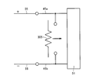
- FIG. 12 is a schematic top view (A) and a schematic cross-sectional view (B) of the internal structure showing a state in which the laser light source unit of FIG. 11 is removed from the housing.
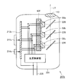
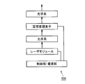
- FIG. 12 is a circuit diagram schematically illustrating a configuration of a laser light source unit in FIG. 11. It is a block diagram which shows roughly the structure of the projection type video display apparatus in Embodiment 5 of this invention.
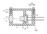
- a laser module (solid light source device) 100a of the present embodiment includes a laser light source unit 50, a housing 101, a first screw (first fixing means) 103, A second screw (second fixing means) 102, a cooling unit 60, and a light emitting unit 113 are included.
- the laser light source unit 50 includes an emitter 51, a can 53, a window 54, and a lead 55.
- the emitter 51 is a laser element that emits light LT, and is formed of, for example, a semiconductor chip.
- the window 54 is attached to the can 53 so as to penetrate the can 53, and transmits the light LT from the emitter 51 to the outside of the can 53.
- the lead 55 is for supplying electric power to the emitter 51 from the outside of the laser light source unit 50. One side of the lead 55 is connected to the emitter 51, and the other side extends to the outside of the housing 101.
- the housing 101 has a lower housing portion (first portion) 101b and an upper housing portion (second portion) 101t.
- the casing lower part 101b and the casing upper part 101t can be combined and removed from each other, and surround the laser light source unit 50 by being combined with each other.
- the can 53 of the laser light source unit 50 is almost sealed, so that the light LT from the laser light source unit 50 does not leak from other than the light emitting unit 113.
- the first screw 103 has a first head portion 103H and a first shaft portion 103E.
- the first head 103H is located outside the housing 101.
- the first shaft portion 103E penetrates the housing upper portion 101t and reaches the housing lower portion 101b.
- the second screw 102 has a second head portion 102H and a second shaft portion 102E.
- the second head 102H is located outside the housing 101.
- the second shaft portion 102E penetrates the housing upper part 101t.
- the second shaft portion 102E has a tip portion.
- the second shaft portion 102E is arranged so that the tip end portion of the second shaft portion 102E is pushed into the laser light source unit 50 by screwing the second screw 102 into the housing upper portion 101t.
- the cooling unit 60 is a component for efficiently removing heat generated from the laser light source unit 50 from the laser light source unit 50, and is a heat sink, for example.
- the light emitting unit 113 is attached to the housing 101 so as to penetrate the housing 101, and transmits the light LT from the laser light source unit 50 to the outside of the housing 101.
- one of the first screw 103 and the second screw 102 is a right-handed screw and the other is a left-handed screw. More preferably, the first screw 103 is a right-handed screw and the second screw 102 is a left-handed screw. .
- a space SP is provided between the second head 102H and the housing upper part 101t so that the second head 102H can be displaced when the second screw 102 is screwed. ing.
- the space SP is a recess formed in the housing upper part 101t.
- the second screw 102 is a plus screw
- the first screw 103 is a screw other than the plus screw.
- the laser light source unit 50 when there is a person (a diverter) who intends to divert the laser light source unit 50 outside the original purpose, the laser light source unit 50 is destroyed. Specifically, when the diverter tries to take out the laser light source unit 50 and try to remove the housing upper part 101t and the housing lower part 101b from each other, the second screw 102 may be screwed, The laser light source unit is destroyed when the tip of the second screw 102 collides with the laser light source unit 50.
- one of the first screw 103 and the second screw 102 is a right-hand screw and the other is a left-hand screw.
- the diverter handles the second screw 102 after removing at least one first screw 103, the operation of turning the second screw 102 in the same direction as turning the first screw 103 is performed. Be triggered. Thereby, the probability that the diverter turns the second screw 102 in the direction opposite to the screwing direction can be reduced.
- the first screw 103 is a right-hand screw and the second screw 102 is a left-hand screw.
- the right-hand thread is more widely used than the left-hand thread. Therefore, when a diverter tries to remove the second screw 102, there is a high possibility that the second screw 102 will be turned counterclockwise. In that case, the second screw 102 is screwed against the will of the diverter to destroy the laser light source unit 50.
- the second screw 102 is a plus screw
- the first screw 103 is a screw other than a plus screw. Accordingly, when the diverter tries to remove the lower housing portion 101b and the upper housing portion 101t from each other with a Phillips screwdriver, the possibility of handling the second screw 102 before the first screw 103 is increased. Thereby, the probability that the diverter will remove the first screw 103 without accidentally handling the second screw 102 can be reduced.
- the laser light source unit 50 is removed by removing the first screw 103 without screwing in the second screw 102.
- the housing upper portion 101t and the housing lower portion 101b of the housing 101 can be detached from each other without destroying the housing 101.
- the laser light source unit 50 of the laser module 100a is not easily diverted inappropriately and can be taken out for maintenance and inspection.
- a laser module 100b as a first modification has a lid portion 110 that covers the first head portion 103H.
- the second shaft portion 102E of the second screw 102 passes through each of the upper housing portion 101t and the lid portion 110.
- the second head portion 102H of the second screw is exposed from the lid portion 110.
- the space SP described above is provided between the second head portion 102H and the lid portion 110 in the present modification. More preferably, the space SP is a recess formed in the lid portion 110.
- the lid that covers the first head 103H of the first screw 103 before removing the first screw 103 in order to remove the lower housing portion 101b and the upper housing portion 101t from each other.
- the part 110 needs to be removed.
- the second screw 102 is first handled. Therefore, it is possible to prevent the diverter from removing the first screw 103 without accidentally handling the second screw 102.
- a laser module 100c as a second modified example has a second screw 102P instead of the second screw 102 (FIG. 1).
- the second screw 102P has a pinch cock-like structure.
- the second screw 102P is a member 102b (second member) that sandwiches the laser light source unit 50 between the member 102a (first member) that is the tip of the second shaft portion 102E and the member 102a. Member).
- the laser module 100c is configured such that both the members 102a and 102b abut against and tighten the laser light source unit 50 by screwing the second screw 102P into the housing upper part 101t.
- the laser light source unit 50 can be surely destroyed when the second screw 102P is screwed.
- the laser module has one laser light source unit.
- the laser module may have a plurality of laser light source units.
- the laser module may have a some light emission part.
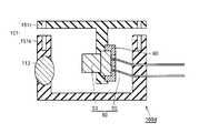
- laser module 100d of the present embodiment has a casing 151 instead of casing 101 (FIG. 1).
- the case 151 includes a case lower part 151b and a case upper part 151t that are detachable and combined with each other and surround the light source unit by being combined with each other.
- the laser light source unit 50 is held by each of the housing lower part 151b and the housing upper part 151t. That is, one side of the laser light source unit 50 is held by the housing lower part 101b, and the other side of the laser light source unit 50 is held by the housing upper part 101t.
- the lead 55 is held by the housing lower part 101b, and the can 53 is held by the housing upper part 101t.
- the diverter when the diverter removes the casing lower portion 151b and the casing upper portion 151t of the casing 151 from each other, as shown in FIG. 6, the casing lower portion 151b and the casing upper portion 151t By changing the relative position, stress is applied to the laser light source unit 50 held in each of the lower housing portion 151b and the upper housing portion 151t. The laser light source unit 50 is broken by this stress. This makes it difficult for the laser light source unit 50 to be inappropriately diverted.
- the can 53 is held by the housing upper part 101t, and the lead 55 is held by the housing lower part 101b.
- a large stress is applied to the root of the lead 55 on the can 53 side, so that the laser light source unit 50 is more reliably destroyed.
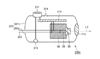
- a laser module 200a of the present embodiment includes a housing 201, a discharge circuit 213, a fixing release switch 211, a fixture 212, a hole (charge removing unit) 214, , Lead 225, power source, power source control unit, and light source control unit.
- the housing 201 has a housing lower portion 201b and a housing upper portion 201t.
- the case lower part 201b and the case upper part 201t can be combined and removed from each other, and surround the laser light source unit 50 by being combined with each other.
- the case lower part 201b and the case upper part 201t are fixed to each other by a fixing tool 212 in a fixed state.
- the lead 225 is connected to the lead 55 and extends to the outside of the housing 201.
- the discharge circuit 213 is provided in the housing 201, and includes a boost converter 213a, a diode 213b, a capacitor (power storage means) 213c, a discharge unit 213d, and a trigger circuit 213e.
- Boost converter 213a is for storing electric charge in capacitor 213c through diode 213b by being connected to a power source. As a result, electric charges are normally stored in the capacitor 213c.
- the discharge unit 213d uses the charge stored in the capacitor 213c to discharge the laser light source unit 50 so that the laser light source unit 50 is deteriorated or destroyed. It is configured as follows.
- the discharge unit 213d supplies a current that is in a direction opposite to the current supplied for light emission of the laser light source unit 50 and has a magnitude that causes the laser light source unit 50 to deteriorate or break down.
- the unit 50 is configured to be supplied.
- the fixing release switch 211 is configured to detach the casing lower part 201b and the casing upper part 201t from each other by releasing the fixing state of the fixture 212 when pressed.
- the fixture 212 is, for example, a hook that extends from the upper housing portion 201t to the lower housing portion 201b, and is configured to be released from being caught by the lower housing portion 201b when the fixing release switch 211 is pressed.
- the lock release switch 211 is electrically connected to the trigger circuit 213e so that the trigger circuit 213e is activated when pressed.
- the hole 214 is for removing electric charge from the capacitor 213c and communicates toward the electrode of the capacitor 213c. Thereby, the electric charge stored in the capacitor 213c can be removed by bringing the grounding rod inserted through the hole 214 into contact with the electrode of the capacitor 213c.
- the discharge circuit 213 discharges the charge to the laser light source unit 50.
- the laser light source 50 is deteriorated or destroyed.
- the laser module 200a of the present embodiment when a diverter removes the housing lower part 201b and the housing upper part 201t from each other by the fixing release switch 211, the electric charge stored in the capacitor 213c is discharged to the laser light source unit 50. As a result, the laser light source unit 50 is deteriorated or destroyed.
- the maintenance inspector since the maintenance inspector has sufficient information about the laser module 200a, the case lower part 201b and the case upper part 201t can be removed from each other after the charge stored in the capacitor 213c is removed using the hole 214.
- the laser light source unit 50 of the laser module 200a is not easily diverted inappropriately and can be taken out for maintenance and inspection.
- a modified laser module 200b includes laser light source units 50a to 50c, a cooling unit 60f, a discharge circuit 213v, a claw 211v, a stop switch (charge removing unit) 214v, And a half mirror 226.
- Each of the laser light source units 50a to 50c emits red, green, and blue light. These lights are white-colored by color synthesis using the half mirror 226, and then emitted to the outside of the laser module 200 b through the light emitting unit 113. Each of the laser light source units 50a to 50c is attached to the cooling unit 60f.
- the discharge circuit 213v has substantially the same configuration as the discharge circuit 213 (FIG. 8), and preferably has a separate capacitor 213c (FIG. 8) for each of the laser light source units 50a to 50c. Alternatively, a single capacitor having a sufficiently large capacity may be used in common for the laser light source units 50a to 50c.
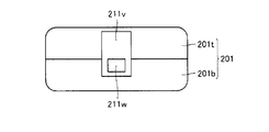
- the claw 211v is attached to the housing upper part 201t, and is usually hooked on the protrusion 211w of the housing lower part 201b.
- the casing lower part 201b and the casing upper part 201t can be removed from each other by removing the claw 211v from the protrusion 211w.
- the claw 211v is electrically connected to the trigger circuit 213e so that the trigger circuit 213e is activated when the claw 211v is removed from the protrusion 211w.
- an electrode is provided on the housing upper portion 201t side of the claw 211v, and when the housing lower portion 201b side of the claw 211v is lifted, power is supplied to the trigger circuit 213e through this electrode.
- the stop switch 214v is for removing charges from the capacitor 213c (not shown in FIG. 9) of the discharge circuit 213v, and is configured to release the charges stored in the capacitor 213c to the ground side when pressed. ing.
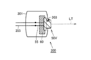
- the laser module 300 of the present embodiment includes a housing 301, a laser light source unit 50 ⁇ / b> V fixed to the housing 301, and leads 355.
- the lead 355 is connected to the lead 55.
- laser light source unit 50V has the same configuration as laser light source unit 50 (FIG. 2), and further includes conductive parts 45a and 45b (first and second conductive parts). ), A pushing portion 303, a connecting portion 304, a conductive bridge portion 305, and a spring 306.
- Each of the conductive portions 45 a and 45 b is connected to the lead 55.
- different potentials are applied to the leads 55 and 55, whereby different potentials are applied to the conductive units 45a and 45b.
- the pushing portion 303 is fixed to the can 53 via a spring 306.
- the pushing unit 303 is pushed into the can 53 against the force of the spring 306.
- the gap between the pushed-in portion 303 and the can 53 has such a narrow dimension that foreign matter such as dust does not enter.
- the outer periphery of the pushed-in portion 303 and the outer periphery of the can 53 are approximately the same.
- the pushing unit 303 projects from the can 53 by the force of the spring 306.
- the bridge unit 305 is connected to the push-in unit 303 through the connection unit 304.
- the bridge portion 305 is configured to be displaced in conjunction with the pushing portion 303.
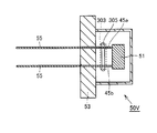
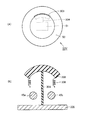
- the bridge unit 305 in a state where the laser light source unit 50V is fixed to the housing 301 (FIGS. 13A and 13B), the bridge unit 305 is positioned away from each of the conductive units 45a and 45b, and the laser In a state in which the light source unit 50V is removed from the housing 301 (FIGS. 14A and 14B), the bridge unit 305 takes a position to electrically short-circuit both by contacting the conductive units 45a and 45b. As described above, the bridge unit 305 is configured to be movable.
- the bridge unit 305 does not affect the circuit configuration of the laser light source unit 50V.
- the bridge unit 305 short-circuits between the conductive units 45a and 45b as indicated by an arrow in FIG. As a result, the voltage applied to the emitter 51 is reduced, so that the emission intensity of the laser light source unit 50V is significantly reduced or zero.
- the bridge unit 305 is a heating element that generates heat when a voltage is applied.
- the laser light source unit 50V is configured to be deteriorated by heat generated by the heating element.
- a configuration in which the light emission capability of the emitter 51 is deteriorated by heat, or a configuration in which wire bonding for electrically connecting the lead 55 and the emitter 51 is disconnected by melting can be used.
- the laser module 300 of the present embodiment when the laser light source unit 50V is removed from the housing 301, the conductive portions 45a and 45b of the laser light source unit 50V are electrically short-circuited, so Power supply is not possible. Thereby, diversion of the laser light source unit 50V can be prevented. Further, although it becomes difficult to function when the laser light source unit 50V is detached from the housing 301, the laser light source unit 50V is not deteriorated or destroyed by being removed. Therefore, the laser light source unit 50V can be taken out without being deteriorated or destroyed by a maintenance inspector. As described above, the laser light source unit 50V of the laser module 300 is not easily diverted inappropriately and can be taken out for maintenance inspection.
- the bridge unit 305 is a heating element that generates heat when a voltage is applied.
- the laser light source unit 50V is deteriorated or destroyed by the heat generated from the bridge unit 305.
- diversion of the laser light source part 50V by a diverter can be prevented more reliably.
- projector 500 projection image display apparatus
- projector 500 includes at least one of the laser modules according to the above-described embodiments, a spatial modulation element, an optical system, a control unit, and a power source.
- the spatial modulation element modulates light emitted from the laser module.
- the spatial modulation element is, for example, a digital mirror device (DMD), a transmissive liquid crystal element, or a reflective liquid crystal element (LCOS).
- the laser light source unit is not likely to be inappropriately diverted and can be taken out for maintenance and inspection.
- 50, 50a to 50c, 50V Laser light source part, 45a conductive part (first conductive part), 45b conductive part (second conductive part), 51 emitter, 53 can, 55 lead, 100a to 100d, 200a, 200b, 300 laser module (solid light source device), 101, 151, 201, 301 housing, 101b, 151b, 201b lower housing portion (first portion), 101t, 151t, 201t upper housing portion (second portion), 102 , 102P second screw, 102a member (first member), 102b member (second member), 102E second shaft portion, 102H second head, 103 first screw, 103E first shaft Part, 103H first head, 110 lid part, 211 fixation release switch, 211v claw, 212 fixture, 213c capacitor 213,213v discharge circuit, 214 holes (charge removal unit), 214V stop switch (charge removal unit), 303 push portion 305 bridge portion, 500 a projector (projection display apparatus).
Landscapes
- Physics & Mathematics (AREA)
- Engineering & Computer Science (AREA)
- General Physics & Mathematics (AREA)
- Optics & Photonics (AREA)
- Computer Security & Cryptography (AREA)
- Multimedia (AREA)
- Signal Processing (AREA)
- Projection Apparatus (AREA)
- Non-Portable Lighting Devices Or Systems Thereof (AREA)
- Fastening Of Light Sources Or Lamp Holders (AREA)
- Lasers (AREA)
Abstract
【課題】不適切に転用されにくくかつ保守点検のためには取り出すことができるレーザ光源部を有する固体光源装置と、それを用いた投写型映像表示装置とを提供する。 【解決手段】筐体101は互いに組み合わされることによってレーザ光源部を取り囲む第1および第2の部分101b、101tを有する。第1の固定手段103は、筐体101の外側に位置する第1の頭部103Hと、第2の部分101tを貫通して第1の部分101b中に達する第1の軸部103Eとを有する。第2の固定手段102は、筐体101の外側に位置する第2の頭部102Hと、第2の部分101tを貫通する第2の軸部102Eとを有する。第2の軸部102Eは、先端部を有し、第2の固定手段102を第2の部分101tに対してねじ込むことにより先端部がレーザ光源部50に押し込まれるように配置されている。
Description
本発明は、レーザ光源部を有する固体光源装置、およびそれを用いた投写型映像表示装置に関する。
近年、高出力のレーザ光源部が搭載されたレーザモジュールを有するコンシューマ製品が提供され始めている。高出力のレーザ光源部を用いることで、より強力な光源が得られる利点がある。一方で、このレーザ光源部が取り出されて不適切な用途に転用される可能性がある。よって強力なレーザ光源部であるほど、本来の用途以外への転用を防止する方法が望まれる。
特開2007-19476号公報(特許文献1)は、レーザ光源部を取り出して悪用することを未然に防止することを意図したレーザ光源装置を開示している。このレーザ光源装置は、レーザ光源部と、レーザ光源部を支持する支持部と、レーザ光源部を支持部に固定する固定部材と、レーザ光源部を支持部から取り外す際に固定部材によるレーザ光源部の固定状態を解除する動きに連動して、レーザ光源部における光発振部に電流を供給する電流経路を遮断する遮断手段とを有する。
特開2009-181984号公報(特許文献2)は、保護筐体から分離した状態での使用を禁止することを意図したレーザモジュールを開示している。このレーザモジュールは、保護筐体の内部に設置されるレーザモジュールであって、光源部と、検知部と、給電部と、制御部とを備えている。検知部は、保護筐体から分離したことを検知する。給電部は、光源部に対して逆電圧を印加する。制御部は、検知部において保護筐体と光源部とが分離したことを検知すると、光源部に対して逆電圧を印加するように給電部を制御する。
特許文献1または2の技術では、不適切な転用の目的においてのみならず、保守点検などの目的においてもレーザ光源部を取り出すことができない。
本発明は、上記の課題に鑑みてなされたものであり、その目的は、不適切に転用されにくくかつ保守点検のためには取り出すことができるレーザ光源部を有する固体光源装置と、それを用いた投写型映像表示装置とを提供することである。
本発明の一の局面に従う固体光源装置は、レーザ光源部と、筐体と、第1の固定手段と、第2の固定手段とを有する。筐体は、互いに組み合わせ・取り外し可能で、かつ互いに組み合わされることによってレーザ光源部を取り囲む第1および第2の部分を有する。第1の固定手段は、筐体の外側に位置する第1の頭部と、第2の部分を貫通して第1の部分中に達する第1の軸部とを有する。第2の固定手段は、筐体の外側に位置する第2の頭部と、第2の部分を貫通する第2の軸部とを有する。第2の軸部は、先端部を有し、第2の固定手段を第2の部分に対してねじ込むことにより先端部がレーザ光源部に押し込まれるように配置されている。
この固体光源装置によれば、レーザ光源部を本来の目的外に転用するために筐体の第1および第2の部分を互いに取り外そうとする者(以下、転用者ともいう)がいた場合に、第2の固定手段がレーザ光源部の破壊を誘発する。また正規の保守点検を行う者(以下、保守点検者ともいう)は、この固体光源装置に関する十分な情報を有するので、第2の固定手段をねじ込まずに第1の固定手段を外すことによって、レーザ光源部を破壊することなく筐体の第1および第2の部分を互いに取り外すことができる。以上のようにこの固体光源装置のレーザ光源部は、不適切に転用されにくく、かつ保守点検のためには取り出すことができる。
好ましくは、固体光源装置は、第1の頭部を覆う蓋部をさらに有する。第2の固定手段の第2の軸部は、筐体の第2の部分と、蓋部との各々を貫通し、かつ第2の固定手段の第2の頭部は蓋部から露出している。
これにより、筐体の第1および第2の部分を互いに取り外すために第1の固定手段を外す前に、第1の固定手段の第1の頭部を覆う蓋部を外す必要がある。蓋部を外すためにはまず第2の固定手段を取り扱うがある。よって転用者が偶然に第2の固定手段を取り扱うことなく第1の固定手段を外してしまうことを、防止することができる。
好ましくは、第2の固定手段は、第2の軸部の先端部となる第1の部材と、第1の部材との間でレーザ光源部を挟み込む第2の部材とを有する。固体光源装置は、第2の固定手段を第2の部分に対してねじ込むことにより第1および第2の部材の双方がレーザ光源部に当たりかつ締め付けるよう構成されている。
これにより、第2の固定手段がねじ込まれた場合により確実にレーザ光源部を破壊することができる。
好ましくは、第1および第2の固定手段の一方は右ねじであり他方は左ねじである。 これにより、転用者が少なくとも1つの第1の固定手段を外した後に第2の固定手段を取り扱う際に、第2の固定手段を第1の固定手段を回したのと同一方向に回す動作が誘発される。これにより、転用者が第2の固定手段をねじ込む方向と反対方向に回す確率を小さくすることができる。
本発明の他の局面に従う固体光源装置は、レーザ光源部と、筐体とを有する。筐体は、互いに組み合わせ・取り外し可能で、かつ互いに組み合わされることによってレーザ光源部を取り囲む第1および第2の部分を有する。レーザ光源部の一方が第1の部分によって保持され、レーザ光源部の他方が第2の部分によって保持されている。
この固体光源装置によれば、転用者が筐体の第1および第2の部分を互いに取り外すと、第1および第2の部分の相対位置が変化することで、第1および第2の部分の各々に保持されているレーザ光源部に応力が加わる。この応力によりレーザ光源部が破壊される。これによりレーザ光源部が不適切に転用されにくくなる。
本発明のさらに他の局面に従う固体光源装置は、レーザ光源部と、筐体と、放電回路と、電荷除去部とを有する。筐体は、互いに組み合わせ・取り外し可能で、かつ互いに組み合わされることによってレーザ光源部を取り囲む第1および第2の部分を有する。放電回路は、筐体中に設けられ、電荷を蓄えることができる蓄電手段を有し、電荷が蓄電手段に蓄えられている場合に第1および第2の部分が互いに取り外されると電荷をレーザ光源部へ放電することによってレーザ光源部を劣化させるものである。電荷除去部は、蓄電手段から電荷を除去することができるものである。
この固体光源装置によれば、転用者が筐体の第1および第2の部分を互いに取り外すと、蓄電手段に蓄えられた電荷がレーザ光源部に放電されることによって、レーザ光源部が劣化される。また保守点検者は、この固体光源装置に関する十分な情報を有するので、蓄電手段に蓄えられた電荷を電荷除去部を用いて除去した後に筐体の第1および第2の部分を互いに取り外すことができる。以上のようにこの固体光源装置のレーザ光源部は、不適切に転用されにくく、かつ保守点検のためには取り出すことができる。
本発明のまたさらに他の局面に従う固体光源装置は、筐体と、筐体に固定されたレーザ光源部とを有する。レーザ光源部は、第1および第2の導電部と、導電性のブリッジ部とを有する。第1および第2の導電部は、レーザ光源部の動作時に互いに異なる電位が印加されるものである。ブリッジ部は、レーザ光源部が筐体に固定された状態で第1および第2の導電部の少なくともいずれかから離れた位置と、レーザ光源部が筐体から取り外された状態で第1および第2の導電部を電気的に短絡する位置との間を移動可能に構成されている。
この固体光源装置によれば、レーザ光源部を筐体から取り外すと、レーザ光源部の第1および第2の導電部が電気的に短絡されることで、レーザ光源部への十分な電力供給ができなくなる。これにより転用者によるレーザ光源部の転用を防止することができる。またレーザ光源部は、筐体から取り外されると機能することが困難となるものの、取り外されたこと自体で劣化または破壊されるわけではない。よってレーザ光源部は保守点検者によって劣化または破壊されることなく取り出され得る。以上のようにこの固体光源装置のレーザ光源部は、不適切に転用されにくく、かつ保守点検のためには取り出すことができる。
本発明の投写型映像表示装置は、上記の固体光源装置の少なくともいずれかと、空間変調素子とを有する。空間変調素子は、固体光源装置から出射された光を変調するものである。
この投写型映像表示装置によれば、そのレーザ光源部を、不適切に転用されにくく、かつ保守点検のためには取り出すことができるものとすることができる。
以上に説明したように本発明の固体光源装置および投写型映像表示装置によれば、レーザ光源部を、不適切に転用されにくく、かつ保守点検のためには取り出すことができるものとすることができる。
以下、本発明の実施の形態について図に基づいて説明する。
(実施の形態1)
図1および図2を参照して、本実施の形態のレーザモジュール(固体光源装置)100aは、レーザ光源部50と、筐体101と、第1のねじ(第1の固定手段)103と、第2のねじ(第2の固定手段)102と、冷却部60と、光出射部113とを有する。
(実施の形態1)
図1および図2を参照して、本実施の形態のレーザモジュール(固体光源装置)100aは、レーザ光源部50と、筐体101と、第1のねじ(第1の固定手段)103と、第2のねじ(第2の固定手段)102と、冷却部60と、光出射部113とを有する。
レーザ光源部50は、エミッタ51と、缶53と、窓54と、リード55とを有する。エミッタ51は、光LTを放出するレーザ素子であり、たとえば半導体チップによって構成されている。窓54は缶53を貫通するように缶53に取り付けられており、エミッタ51からの光LTを缶53の外部へと透過させるものである。リード55は、レーザ光源部50の外部からエミッタ51へ電力を供給するためのものである。リード55の一方側はエミッタ51に接続されており、他方側は筐体101の外部へ延びている。
筐体101は筐体下部(第1の部分)101bおよび筐体上部(第2の部分)101tを有する。筐体下部101bおよび筐体上部101tは、互いに組み合わせ・取り外し可能で、かつ互いに組み合わされることによってレーザ光源部50を取り囲んでいる。これによりレーザ光源部50の缶53がほぼ密閉されており、よってレーザ光源部50からの光LTが光出射部113以外から漏れないようにされている。
第1のねじ103は第1の頭部103Hおよび第1の軸部103Eを有する。第1の頭部103Hは筐体101の外側に位置している。第1の軸部103Eは筐体上部101tを貫通して筐体下部101b中に達している。
第2のねじ102は第2の頭部102Hおよび第2の軸部102Eを有する。第2の頭部102Hは筐体101の外側に位置している。第2の軸部102Eは筐体上部101tを貫通している。第2の軸部102Eは先端部を有する。また第2の軸部102Eは、第2のねじ102を筐体上部101tに対してねじ込むことにより第2の軸部102Eの先端部がレーザ光源部50に押し込まれるように配置されている。
冷却部60は、レーザ光源部50から生じる熱をレーザ光源部50から効率的に除去するための部品であり、たとえばヒートシンクである。光出射部113は、筐体101を貫通するように筐体101に取り付けられており、レーザ光源部50からの光LTを筐体101の外部へ透過させるものである。
好ましくは第1のねじ103および第2のねじ102の一方は右ねじであり他方は左ねじであり、より好ましくは第1のねじ103が右ねじであり第2のねじ102が左ねじである。また好ましくは、第2の頭部102Hと筐体上部101tとの間に、第2のねじ102がねじ込まれた際に第2の頭部102Hが変位できるようにするための空間SPが設けられている。好ましくは空間SPは、筐体上部101tに形成された凹部である。また好ましくは第2のねじ102はプラスねしであり、第1のねじ103はプラスねじ以外のねじである。
本実施の形態のレーザモジュール100aによれば、レーザ光源部50を本来の目的外に転用しようとする者(転用者)がいた場合に、レーザ光源部50の破壊が誘発される。具体的には、転用者がレーザ光源部50を取り出そうとして筐体上部101tおよび筐体下部101bを互いに取り外そうとする際に、第2のねじ102をねじ込む可能性があり、その場合、第2のねじ102の先端部がレーザ光源部50と衝突するすることによってレーザ光源部が破壊される。
好ましくは、第1のねじ103および第2のねじ102の一方は右ねじであり他方は左ねじである。これにより、転用者が少なくとも1つの第1のねじ103を外した後に第2のねじ102を取り扱う際に、第2のねじ102を第1のねじ103を回したのと同一方向に回す動作が誘発される。これにより、転用者が第2のねじ102をねじ込む方向と反対方向に回す確率を小さくすることができる。
より好ましくは、第1のねじ103が右ねじであり、第2のねじ102が左ねじである。一般に左ねじに比して右ねじの方が広く用いられていることから、転用者が第2のねじ102を取り外そうとする際に第2のねじ102を左周りに回す可能性が高く、その場合、転用者の意に反して第2のねじ102はねじ込まれることでレーザ光源部50を破壊する。
また好ましくは第2のねじ102はプラスねしであり、第1のねじ103はプラスねじ以外のねじである。これにより転用者がプラスドライバーによって筐体下部101bおよび筐体上部101tを互いに取り外そうとした場合に、第1のねじ103より先に第2のねじ102を取り扱う可能性が高くなる。これにより、転用者が偶然に第2のねじ102を扱うことなく第1のねじ103を取り外してしまう確率を小さくすることができる。
一方、正規の保守点検を行う者(保守点検者)は、レーザモジュール100aに関する十分な情報を有するので、第2のねじ102をねじ込まずに第1のねじ103を外すことによって、レーザ光源部50を破壊することなく筐体101の筐体上部101tおよび筐体下部101bを互いに取り外すことができる。
以上のようにこのレーザモジュール100aのレーザ光源部50は、不適切に転用されにくく、かつ保守点検のためには取り出すことができる。
図3を参照して、第1の変形例としてのレーザモジュール100bは、第1の頭部103Hを覆う蓋部110を有する。本変形例においては第2のねじ102の第2の軸部102Eは、筐体上部101tと、蓋部110との各々を貫通している。第2のねじの第2の頭部102Hは蓋部110から露出している。なお前述した空間SPは本変形例においては、第2の頭部102Hと蓋部110との間に設けられる。より好ましくは空間SPは、蓋部110に形成された凹部である。
本変形例のレーザモジュール100bによれば、筐体下部101bおよび筐体上部101tを互いに取り外すために第1のねじ103を外す前に、第1のねじ103の第1の頭部103Hを覆う蓋部110を外す必要がある。蓋部110を外すためにはまず第2のねじ102を取り扱うがある。よって転用者が偶然に第2のねじ102を取り扱うことなく第1のねじ103を外してしまうことを防止することができる。
図4を参照して、第2の変形例としてのレーザモジュール100cは第2のねじ102(図1)の代わりに第2のねじ102Pを有する。第2のねじ102Pはピンチコック状の構造を有する。具体的には、第2のねじ102Pは、第2の軸部102Eの先端部となる部材102a(第1の部材)と、部材102aとの間でレーザ光源部50を挟み込む部材102b(第2の部材)とを有する。レーザモジュール100cは、第2のねじ102Pを筐体上部101tに対してねじ込むことにより部材102aおよび102bの双方がレーザ光源部50に当たりかつ締め付けるよう構成されている。
本変形例のレーザモジュール100cによれば、第2のねじ102Pがねじ込まれた場合により確実にレーザ光源部50を破壊することができる。
なお本実施の形態においてはレーザモジュールが1つのレーザ光源部を有する場合について説明したが、レーザモジュールは複数のレーザ光源部を有してもよい。またレーザモジュールが1つの光出射部を有する場合について説明したが、レーザモジュールは複数の光出射部を有してもよい。
(実施の形態2)
図5を参照して、本実施の形態のレーザモジュール100dは、筐体101(図1)の代わりに筐体151とを有する。筐体151は、互いに組み合わせ・取り外し可能で、かつ互いに組み合わされることによって光源部を取り囲む筐体下部151bおよび筐体上部151tを有する。レーザ光源部50は筐体下部151bおよび筐体上部151tの各々によって保持されている。すなわちレーザ光源部50の一方が筐体下部101bによって保持されており、レーザ光源部50の他方が筐体上部101tによって保持されている。好ましくは、リード55が筐体下部101bに保持されており、缶53が筐体上部101tによって保持されている。
図5を参照して、本実施の形態のレーザモジュール100dは、筐体101(図1)の代わりに筐体151とを有する。筐体151は、互いに組み合わせ・取り外し可能で、かつ互いに組み合わされることによって光源部を取り囲む筐体下部151bおよび筐体上部151tを有する。レーザ光源部50は筐体下部151bおよび筐体上部151tの各々によって保持されている。すなわちレーザ光源部50の一方が筐体下部101bによって保持されており、レーザ光源部50の他方が筐体上部101tによって保持されている。好ましくは、リード55が筐体下部101bに保持されており、缶53が筐体上部101tによって保持されている。
なお、上記以外の構成については、上述した実施の形態1の構成とほぼ同じであるため、同一または対応する要素について同一の符号を付し、その説明を繰り返さない。
本実施の形態のレーザモジュール100dによれば、転用者が筐体151の筐体下部151bおよび筐体上部151tを互いに取り外すと、図6に示すように、筐体下部151bおよび筐体上部151tの相対位置が変化することで、筐体下部151bおよび筐体上部151tの各々に保持されているレーザ光源部50に応力が加わる。この応力によりレーザ光源部50が破壊される。これによりレーザ光源部50が不適切に転用されにくくなる。
好ましくは、缶53が筐体上部101tによって保持されており、リード55が筐体下部101bに保持されている。これによりリード55の缶53側の付け根に大きな応力が加わるので、レーザ光源部50がより確実に破壊される。
(実施の形態3)
図7および図8を参照して、本実施の形態のレーザモジュール200aは、筐体201と、放電回路213と、固定解除スイッチ211と、固定具212と、穴部(電荷除去部)214と、リード225と、電源と、電源制御部と、光源制御部とを有する。
図7および図8を参照して、本実施の形態のレーザモジュール200aは、筐体201と、放電回路213と、固定解除スイッチ211と、固定具212と、穴部(電荷除去部)214と、リード225と、電源と、電源制御部と、光源制御部とを有する。
筐体201は筐体下部201bおよび筐体上部201tを有する。筐体下部201bおよび筐体上部201tは、互いに組み合わせ・取り外し可能で、かつ互いに組み合わされることによってレーザ光源部50を取り囲んでいる。筐体下部201bおよび筐体上部201tは、固定状態にある固定具212によって互いに固定されている。リード225は、リード55に接続されており、筐体201の外部へ延びている。
放電回路213は、筐体201中に設けられており、昇圧コンバータ213aと、ダイオード213bと、コンデンサ(蓄電手段)213cと、放電部213dと、トリガ回路213eとを有する。昇圧コンバータ213aは電源に接続されることによってダイオード213bを介してコンデンサ213cに電荷を蓄えるためのものである。これによりコンデンサ213cには、通常、電荷が蓄えられている。放電部213dは、トリガ回路213eからのトリガが入力された場合に、コンデンサ213cに蓄えられた電荷を用いてレーザ光源部50に対して、レーザ光源部50が劣化または破壊するような放電を行うように構成されている。具体的には、放電部213dは、レーザ光源部50の発光のために供給される電流とは逆方向の電流であって、かつレーザ光源部50が劣化または破壊する大きさの電流をレーザ光源部50に供給するように構成されている。
固定解除スイッチ211は、押下されると固定具212の固定状態を解除することによって、筐体下部201bおよび筐体上部201tを互いに取り外すように構成されている。固定具212は、たとえば筐体上部201tから筐体下部201bへと延びるフックであり、固定解除スイッチ211の押下によって筐体下部201bとの引っ掛かりが外れるように構成されている。また固定解除スイッチ211は、押下されるとトリガ回路213eを起動するように、トリガ回路213eに電気的に接続されている。
穴部214は、コンデンサ213cから電荷を除去するためのものであり、コンデンサ213cの電極に向かって通じている。これにより、穴部214から挿入したアース棒をコンデンサ213cの電極に接触させることによって、コンデンサ213cに蓄えられた電荷を除去することができる。
上記構成により、電荷がコンデンサ213cに蓄えられている場合に固定解除スイッチ211によって筐体下部201bおよび筐体上部201tが互いに取り外されると、放電回路213は、電荷をレーザ光源部50へ放電することによってレーザ光源部50を劣化または破壊する。
なお、上記以外の構成については、上述した実施の形態1の構成とほぼ同じであるため、同一または対応する要素について同一の符号を付し、その説明を繰り返さない。
本実施の形態のレーザモジュール200aによれば、転用者が固定解除スイッチ211によって筐体下部201bおよび筐体上部201tを互いに取り外すと、コンデンサ213cに蓄えられた電荷がレーザ光源部50に放電されることによって、レーザ光源部50が劣化または破壊される。一方、保守点検者はレーザモジュール200aに関する十分な情報を有するので、コンデンサ213cに蓄えられた電荷を穴部214を用いて除去した後に筐体下部201bおよび筐体上部201tを互いに取り外すことができる。
以上のようにレーザモジュール200aのレーザ光源部50は、不適切に転用されにくく、かつ保守点検のためには取り出すことができる。
図9および図10を参照して、変形例としてのレーザモジュール200bは、レーザ光源部50a~50cと、冷却部60fと、放電回路213vと、爪211vと、停止スイッチ(電荷除去部)214vと、ハーフミラー226とを有する。
レーザ光源部50a~50cのそれぞれは、赤色、緑色、および青色の光を発光するものである。これらの光は、ハーフミラー226を用いて色合成されることによって白色光とされた上で、光出射部113を通ってレーザモジュール200bの外部へ出射される。レーザ光源部50a~50cの各々は、冷却部60fに取り付けられている。
放電回路213vは、放電回路213(図8)とほぼ同様の構成を有し、好ましくはレーザ光源部50a~50cごとに別個のコンデンサ213c(図8)を有する。なお代わりに、十分大きな容量を有する1つのコンデンサがレーザ光源部50a~50cに対して共用で用いられてもよい。
爪211vは、筐体上部201tに取り付けられており、通常、筐体下部201bの突起211wに引っ掛けられている。爪211vが突起211wから外されることによって筐体下部201bおよび筐体上部201tを互いに取り外すことができる。また爪211vは、突起211wから外されるとトリガ回路213eを起動するように、トリガ回路213eに電気的に接続されている。たとえば、爪211vの筐体上部201t側に電極が設けられており、爪211vの筐体下部201b側が持ち上げられると、この電極を通じてトリガ回路213eに電力が供給される。
停止スイッチ214vは、放電回路213vのコンデンサ213c(図9において図示せず)から電荷を除去するためのものであり、押下されるとコンデンサ213cに蓄えられた電荷をアース側へ逃がすように構成されている。
(実施の形態4)
図11を参照して、本実施の形態のレーザモジュール300は、筐体301と、筐体301に固定されたレーザ光源部50Vと、リード355とを有する。リード355はリード55に接続されている。
図11を参照して、本実施の形態のレーザモジュール300は、筐体301と、筐体301に固定されたレーザ光源部50Vと、リード355とを有する。リード355はリード55に接続されている。
主に図12~図14を参照して、レーザ光源部50Vは、レーザ光源部50(図2)と同様の構成を有し、さらに、導電部45aおよび45b(第1および第2の導電部)と、押込部303と、連結部304と、導電性のブリッジ部305と、ばね306とを有する。
導電部45aおよび45bの各々はリード55に接続されている。レーザ光源部50Vの動作時には、リード55、55に異なる電位が印加されることによって、導電部45aおよび45bに互いに異なる電位が印加される。
押込部303はばね306を介して缶53に固定されている。レーザ光源部50Vが筐体301に固定されている状態(図13(A)および(B))では、押込部303はばね306の力に逆らって缶53内に押し込まれている。好ましくは、押し込まれた押込部303と缶53との間の隙間は、埃などの異物が侵入しない程度に狭い寸法を有する。また押し込まれた押込部303の外周と缶53の外周とはおおよそ一致している。レーザ光源部50Vが筐体301から取り外された状態(図14(A)および(B))では、押込部303はばね306の力によって缶53から突出している。
ブリッジ部305は連結部304を介して押込部303に連結されている。これによりブリッジ部305は、押込部303と連動して変位するように構成されている。具体的には、レーザ光源部50Vが筐体301に固定されている状態(図13(A)および(B))ではブリッジ部305は導電部45aおよび45bの各々から離れた位置をとり、レーザ光源部50Vが筐体301から取り外された状態(図14(A)および(B))ではブリッジ部305は導電部45aおよび45bの各々に接触することによって両者を電気的に短絡する位置をとるように、ブリッジ部305は移動可能に構成されている。
さらに図15を参照して、レーザ光源部50Vが筐体301に固定されている状態では、ブリッジ部305はレーザ光源部50Vの回路構成に影響しない。レーザ光源部50Vが筐体301から取り外された状態では、図15の矢印に示すように、ブリッジ部305は導電部45aおよび45bの間を短絡する。これによりエミッタ51に印加される電圧が低下するので、レーザ光源部50Vの発光強度が大幅に低下するか、またはゼロとなる。
好ましくは、ブリッジ部305は、電圧が印加されると発熱する発熱素子である。この場合、レーザ光源部50Vは発熱素子の発熱によって劣化するように構成されている。このような構成としては、たとえば、熱によってエミッタ51の発光能力が劣化する構成、またはリード55とエミッタ51との間を電気的に接続するワイヤボンディングが溶融によって断線する構成を用いることができる。
なお、上記以外の構成については、上述した実施の形態1の構成とほぼ同じであるため、同一または対応する要素について同一の符号を付し、その説明を繰り返さない。
本実施の形態のレーザモジュール300によれば、レーザ光源部50Vを筐体301から取り外すと、レーザ光源部50Vの導電部45aおよび45bが電気的に短絡されることでレーザ光源部50Vへの十分な電力供給ができなくなる。これにより転用者によるレーザ光源部50Vの転用を防止することができる。またレーザ光源部50Vは、筐体301から取り外されると機能することが困難となるものの、取り外されたこと自体で劣化または破壊されるわけではない。よってレーザ光源部50Vは保守点検者によって劣化または破壊されることなく取り出され得る。以上のようにレーザモジュール300のレーザ光源部50Vは、不適切に転用されにくく、かつ保守点検のためには取り出すことができる。
好ましくは、ブリッジ部305は、電圧が印加されると発熱する発熱素子である。これにより、転用者がレーザ光源部50Vの使用を試みると、ブリッジ部305からの発熱によってレーザ光源部50Vが劣化または破壊される。これにより、転用者によるレーザ光源部50Vの転用をより確実に防止することができる。
(実施の形態5)
図16を参照して、本実施の形態のプロジェクタ500(投写型映像表示装置)は、前述した各実施の形態のレーザモジュールの少なくともいずれかと、空間変調素子と、光学系と、制御部・電源部とを有する。空間変調素子は、レーザモジュールから出射された光を変調するものである。空間変調素子は、たとえば、デジタルミラーデバイス(DMD:Digital Mirror Device)、透過型液晶素子、または反射型液晶素子(LCOS:Liquid Crystal On Silicon)である。
図16を参照して、本実施の形態のプロジェクタ500(投写型映像表示装置)は、前述した各実施の形態のレーザモジュールの少なくともいずれかと、空間変調素子と、光学系と、制御部・電源部とを有する。空間変調素子は、レーザモジュールから出射された光を変調するものである。空間変調素子は、たとえば、デジタルミラーデバイス(DMD:Digital Mirror Device)、透過型液晶素子、または反射型液晶素子(LCOS:Liquid Crystal On Silicon)である。
本実施の形態のプロジェクタ500によれば、そのレーザ光源部を、不適切に転用されにくく、かつ保守点検のためには取り出すことができるものとすることができる。
今回開示された実施の形態はすべての点で例示であって、制限的なものではないと考えられるべきである。本発明の範囲は上記した説明ではなくて特許請求の範囲によって示され、特許請求の範囲と均等の意味、および範囲内でのすべての変更が含まれることが意図される。
50,50a~50c,50V レーザ光源部、45a 導電部(第1の導電部)、45b 導電部(第2の導電部)、51 エミッタ、53 缶、55 リード、100a~100d,200a,200b,300 レーザモジュール(固体光源装置)、101,151,201,301 筐体、101b,151b,201b 筐体下部(第1の部分)、101t,151t,201t 筐体上部(第2の部分)、102,102P 第2のねじ、102a 部材(第1の部材)、102b 部材(第2の部材)、102E 第2の軸部、102H 第2の頭部、103 第1のねじ、103E 第1の軸部、103H 第1の頭部、110 蓋部、211 固定解除スイッチ、211v 爪、212 固定具、213c コンデンサ、213,213v 放電回路、214 穴部(電荷除去部)、214v 停止スイッチ(電荷除去部)、303 押込部、305 ブリッジ部、500 プロジェクタ(投写型映像表示装置)。
Claims (8)
- レーザ光源部と、
互いに組み合わせ・取り外し可能で、かつ互いに組み合わされることによって前記レーザ光源部を取り囲む第1および第2の部分を有する筐体と、
前記筐体の外側に位置する第1の頭部と、前記第2の部分を貫通して前記第1の部分中に達する第1の軸部とを有する第1の固定手段と、
前記筐体の外側に位置する第2の頭部と、前記第2の部分を貫通する第2の軸部とを有する第2の固定手段とを備え、
前記第2の軸部は、先端部を有し、前記第2の固定手段を前記第2の部分に対してねじ込むことにより前記先端部が前記レーザ光源部に押し込まれるように配置されている、固体光源装置。 - 前記第1の頭部を覆う蓋部をさらに備え、
前記第2の固定手段の前記第2の軸部は、前記筐体の前記第2の部分と、前記蓋部との各々を貫通し、かつ前記第2の固定手段の前記第2の頭部は前記蓋部から露出している、請求項1に記載の固体光源装置。 - 前記第2の固定手段は、前記第2の軸部の前記先端部となる第1の部材と、前記第1の部材との間で前記レーザ光源部を挟み込む第2の部材とを有し、
前記第2の固定手段を前記第2の部分に対してねじ込むことにより前記第1および第2の部材の双方が前記レーザ光源部に当たりかつ締め付けるよう構成されている、請求項1または2に記載の固体光源装置。 - 前記第1および第2の固定手段の一方は右ねじであり他方は左ねじである、請求項1~3のいずれか1項に記載の固体光源装置。
- レーザ光源部と、
互いに組み合わせ・取り外し可能で、かつ互いに組み合わされることによって前記レーザ光源部を取り囲む第1および第2の部分を有する筐体とを備え、
前記レーザ光源部の一方が前記第1の部分によって保持され、前記レーザ光源部の他方が前記第2の部分によって保持されている、固体光源装置。 - レーザ光源部と、
互いに組み合わせ・取り外し可能で、かつ互いに組み合わされることによって前記レーザ光源部を取り囲む第1および第2の部分を有する筐体と、
前記筐体中に設けられ、電荷を蓄えることができる蓄電手段を有し、前記電荷が前記蓄電手段に蓄えられている場合に前記第1および第2の部分が互いに取り外されると前記電荷を前記レーザ光源部へ放電することによって前記レーザ光源部を劣化させる放電回路と、
前記蓄電手段から前記電荷を除去することができる電荷除去部とを備える、固体光源装置。 - 筐体と、
前記筐体に固定されたレーザ光源部とを備え、
前記レーザ光源部は、
前記レーザ光源部の動作時に互いに異なる電位が印加される第1および第2の導電部と、
前記レーザ光源部が前記筐体に固定された状態で前記第1および第2の導電部の少なくともいずれかから離れた位置と、前記レーザ光源部が前記筐体から取り外された状態で前記第1および第2の導電部を電気的に短絡する位置との間を移動可能に構成された導電性のブリッジ部とを備える、固体光源装置。 - 請求項1~7のいずれか1項に記載の固体光源装置と、
前記固体光源装置から出射された光を変調する空間変調素子とを備える、投写型映像表示装置。
Applications Claiming Priority (2)
| Application Number | Priority Date | Filing Date | Title |
|---|---|---|---|
| JP2010221819A JP2012079477A (ja) | 2010-09-30 | 2010-09-30 | 固体光源装置および投写型映像表示装置 |
| JP2010-221819 | 2010-09-30 |
Publications (1)
| Publication Number | Publication Date |
|---|---|
| WO2012043262A1 true WO2012043262A1 (ja) | 2012-04-05 |
Family
ID=45892729
Family Applications (1)
| Application Number | Title | Priority Date | Filing Date |
|---|---|---|---|
| PCT/JP2011/071133 Ceased WO2012043262A1 (ja) | 2010-09-30 | 2011-09-15 | 固体光源装置および投写型映像表示装置 |
Country Status (2)
| Country | Link |
|---|---|
| JP (1) | JP2012079477A (ja) |
| WO (1) | WO2012043262A1 (ja) |
Cited By (1)
| Publication number | Priority date | Publication date | Assignee | Title |
|---|---|---|---|---|
| CN109557755B (zh) * | 2017-09-26 | 2021-11-19 | 卡西欧计算机株式会社 | 防尘壳体、光源装置以及投影装置 |
Families Citing this family (2)
| Publication number | Priority date | Publication date | Assignee | Title |
|---|---|---|---|---|
| RU2599406C2 (ru) * | 2011-01-06 | 2016-10-10 | Конинклейке Филипс Электроникс Н.В. | Предотвращение несанкционированного доступа к лазерному источнику |
| JP7633535B2 (ja) * | 2020-02-13 | 2025-02-20 | 日亜化学工業株式会社 | 発光モジュール |
Citations (10)
| Publication number | Priority date | Publication date | Assignee | Title |
|---|---|---|---|---|
| JPH0535602A (ja) * | 1991-07-30 | 1993-02-12 | Nec Corp | Romプログラムセキユリテイ装置 |
| JP2001332050A (ja) * | 2000-05-22 | 2001-11-30 | Hitachi Ltd | 移動検出機能を有する情報記録媒体 |
| JP2002111109A (ja) * | 2000-09-29 | 2002-04-12 | Nec Eng Ltd | 円筒状物体の芯出し構造 |
| JP2002353388A (ja) * | 2001-05-30 | 2002-12-06 | Hitachi Ltd | 半導体装置 |
| JP2004055019A (ja) * | 2002-07-18 | 2004-02-19 | Fuji Electric Holdings Co Ltd | 開封検知作動機構付ハードディスク装置 |
| JP2004110929A (ja) * | 2002-09-18 | 2004-04-08 | Nippon Telegr & Teleph Corp <Ntt> | 不正コピー防止蓄積装置および不正コピー防止方法 |
| JP2004325922A (ja) * | 2003-04-25 | 2004-11-18 | Kyocera Mita Corp | 光学走査装置 |
| WO2007023916A1 (ja) * | 2005-08-26 | 2007-03-01 | Matsushita Electric Industrial Co., Ltd. | 投写型ディスプレイ装置 |
| JP2007287081A (ja) * | 2006-04-20 | 2007-11-01 | Nec Infrontia Corp | 耐タンパー方法及びそれを適用した耐タンパー装置、並びに耐タンパー装置用制御プログラム |
| JP2009164443A (ja) * | 2008-01-09 | 2009-07-23 | Seiko Epson Corp | 光源装置、照明装置及び画像表示装置 |
-
2010
- 2010-09-30 JP JP2010221819A patent/JP2012079477A/ja not_active Withdrawn
-
2011
- 2011-09-15 WO PCT/JP2011/071133 patent/WO2012043262A1/ja not_active Ceased
Patent Citations (10)
| Publication number | Priority date | Publication date | Assignee | Title |
|---|---|---|---|---|
| JPH0535602A (ja) * | 1991-07-30 | 1993-02-12 | Nec Corp | Romプログラムセキユリテイ装置 |
| JP2001332050A (ja) * | 2000-05-22 | 2001-11-30 | Hitachi Ltd | 移動検出機能を有する情報記録媒体 |
| JP2002111109A (ja) * | 2000-09-29 | 2002-04-12 | Nec Eng Ltd | 円筒状物体の芯出し構造 |
| JP2002353388A (ja) * | 2001-05-30 | 2002-12-06 | Hitachi Ltd | 半導体装置 |
| JP2004055019A (ja) * | 2002-07-18 | 2004-02-19 | Fuji Electric Holdings Co Ltd | 開封検知作動機構付ハードディスク装置 |
| JP2004110929A (ja) * | 2002-09-18 | 2004-04-08 | Nippon Telegr & Teleph Corp <Ntt> | 不正コピー防止蓄積装置および不正コピー防止方法 |
| JP2004325922A (ja) * | 2003-04-25 | 2004-11-18 | Kyocera Mita Corp | 光学走査装置 |
| WO2007023916A1 (ja) * | 2005-08-26 | 2007-03-01 | Matsushita Electric Industrial Co., Ltd. | 投写型ディスプレイ装置 |
| JP2007287081A (ja) * | 2006-04-20 | 2007-11-01 | Nec Infrontia Corp | 耐タンパー方法及びそれを適用した耐タンパー装置、並びに耐タンパー装置用制御プログラム |
| JP2009164443A (ja) * | 2008-01-09 | 2009-07-23 | Seiko Epson Corp | 光源装置、照明装置及び画像表示装置 |
Cited By (1)
| Publication number | Priority date | Publication date | Assignee | Title |
|---|---|---|---|---|
| CN109557755B (zh) * | 2017-09-26 | 2021-11-19 | 卡西欧计算机株式会社 | 防尘壳体、光源装置以及投影装置 |
Also Published As
| Publication number | Publication date |
|---|---|
| JP2012079477A (ja) | 2012-04-19 |
Similar Documents
| Publication | Publication Date | Title |
|---|---|---|
| EP3121649B1 (en) | Light source device and image projection device having light source device | |
| CN104460203B (zh) | 荧光发光装置以及具备该荧光发光装置的投影仪 | |
| JP5841126B2 (ja) | 発光装置、照明装置、前照灯および車両 | |
| KR101114613B1 (ko) | 광원에 레이저를 이용한 광원장치 및 프로젝터 | |
| JP4970602B2 (ja) | 投写型ディスプレイ装置 | |
| US20040032736A1 (en) | Image projector system having a light source that includes at least four light emitting diode modules | |
| JP2011215332A (ja) | 光源ユニット及びプロジェクタ | |
| JP2012079477A (ja) | 固体光源装置および投写型映像表示装置 | |
| US7111944B2 (en) | Image projector | |
| US20130265553A1 (en) | Projection display device | |
| JP2012208205A (ja) | 半導体光源装置及びプロジェクタ | |
| JP5606895B2 (ja) | 投写型表示装置 | |
| JPH10239767A (ja) | プロジェクタ | |
| JP2016033668A (ja) | 半導体光源装置及びプロジェクタ | |
| JP2006098979A (ja) | プロジェクタ | |
| JP2007227422A (ja) | 半導体装置及び半導体装置を用いた光学ユニット | |
| JP6468421B2 (ja) | 点灯装置 | |
| JP5436169B2 (ja) | 光源装置 | |
| JP2005340023A (ja) | 冷陰極蛍光管駆動回路 | |
| US20190025682A1 (en) | Electro-optical device, lighting device, and projector | |
| JP2006032376A (ja) | 冷却ファン駆動装置 | |
| JP2008123138A (ja) | 電子機器 | |
| JP2015050191A (ja) | 交流電圧を用いた発光ダイオードランプ | |
| JP2607693Y2 (ja) | 放電灯点灯装置 | |
| JP2020020820A (ja) | 投写型表示装置 |
Legal Events
| Date | Code | Title | Description |
|---|---|---|---|
| 121 | Ep: the epo has been informed by wipo that ep was designated in this application |
Ref document number: 11828822 Country of ref document: EP Kind code of ref document: A1 |
|
| NENP | Non-entry into the national phase |
Ref country code: DE |
|
| 122 | Ep: pct application non-entry in european phase |
Ref document number: 11828822 Country of ref document: EP Kind code of ref document: A1 |