WO2012043011A1 - Introducer sheath, placement device for blood vessel treatment instrument, and method for shortening introducer sheath - Google Patents
Introducer sheath, placement device for blood vessel treatment instrument, and method for shortening introducer sheath Download PDFInfo
- Publication number
- WO2012043011A1 WO2012043011A1 PCT/JP2011/065757 JP2011065757W WO2012043011A1 WO 2012043011 A1 WO2012043011 A1 WO 2012043011A1 JP 2011065757 W JP2011065757 W JP 2011065757W WO 2012043011 A1 WO2012043011 A1 WO 2012043011A1
- Authority
- WO
- WIPO (PCT)
- Prior art keywords
- sheath
- hub
- sheath body
- introducer sheath
- introducer
- Prior art date
Links
Images


Classifications
-
- A—HUMAN NECESSITIES
- A61—MEDICAL OR VETERINARY SCIENCE; HYGIENE
- A61F—FILTERS IMPLANTABLE INTO BLOOD VESSELS; PROSTHESES; DEVICES PROVIDING PATENCY TO, OR PREVENTING COLLAPSING OF, TUBULAR STRUCTURES OF THE BODY, e.g. STENTS; ORTHOPAEDIC, NURSING OR CONTRACEPTIVE DEVICES; FOMENTATION; TREATMENT OR PROTECTION OF EYES OR EARS; BANDAGES, DRESSINGS OR ABSORBENT PADS; FIRST-AID KITS
- A61F2/00—Filters implantable into blood vessels; Prostheses, i.e. artificial substitutes or replacements for parts of the body; Appliances for connecting them with the body; Devices providing patency to, or preventing collapsing of, tubular structures of the body, e.g. stents
- A61F2/95—Instruments specially adapted for placement or removal of stents or stent-grafts
- A61F2/962—Instruments specially adapted for placement or removal of stents or stent-grafts having an outer sleeve
- A61F2/97—Instruments specially adapted for placement or removal of stents or stent-grafts having an outer sleeve the outer sleeve being splittable
-
- A—HUMAN NECESSITIES
- A61—MEDICAL OR VETERINARY SCIENCE; HYGIENE
- A61F—FILTERS IMPLANTABLE INTO BLOOD VESSELS; PROSTHESES; DEVICES PROVIDING PATENCY TO, OR PREVENTING COLLAPSING OF, TUBULAR STRUCTURES OF THE BODY, e.g. STENTS; ORTHOPAEDIC, NURSING OR CONTRACEPTIVE DEVICES; FOMENTATION; TREATMENT OR PROTECTION OF EYES OR EARS; BANDAGES, DRESSINGS OR ABSORBENT PADS; FIRST-AID KITS
- A61F2/00—Filters implantable into blood vessels; Prostheses, i.e. artificial substitutes or replacements for parts of the body; Appliances for connecting them with the body; Devices providing patency to, or preventing collapsing of, tubular structures of the body, e.g. stents
- A61F2/95—Instruments specially adapted for placement or removal of stents or stent-grafts
- A61F2/9517—Instruments specially adapted for placement or removal of stents or stent-grafts handle assemblies therefor
-
- A—HUMAN NECESSITIES
- A61—MEDICAL OR VETERINARY SCIENCE; HYGIENE
- A61M—DEVICES FOR INTRODUCING MEDIA INTO, OR ONTO, THE BODY; DEVICES FOR TRANSDUCING BODY MEDIA OR FOR TAKING MEDIA FROM THE BODY; DEVICES FOR PRODUCING OR ENDING SLEEP OR STUPOR
- A61M25/00—Catheters; Hollow probes
- A61M25/0097—Catheters; Hollow probes characterised by the hub
-
- A—HUMAN NECESSITIES
- A61—MEDICAL OR VETERINARY SCIENCE; HYGIENE
- A61M—DEVICES FOR INTRODUCING MEDIA INTO, OR ONTO, THE BODY; DEVICES FOR TRANSDUCING BODY MEDIA OR FOR TAKING MEDIA FROM THE BODY; DEVICES FOR PRODUCING OR ENDING SLEEP OR STUPOR
- A61M25/00—Catheters; Hollow probes
- A61M25/01—Introducing, guiding, advancing, emplacing or holding catheters
- A61M25/06—Body-piercing guide needles or the like
- A61M25/0662—Guide tubes
- A61M25/0668—Guide tubes splittable, tear apart
- A61M2025/0675—Introducing-sheath slitters
-
- A—HUMAN NECESSITIES
- A61—MEDICAL OR VETERINARY SCIENCE; HYGIENE
- A61M—DEVICES FOR INTRODUCING MEDIA INTO, OR ONTO, THE BODY; DEVICES FOR TRANSDUCING BODY MEDIA OR FOR TAKING MEDIA FROM THE BODY; DEVICES FOR PRODUCING OR ENDING SLEEP OR STUPOR
- A61M25/00—Catheters; Hollow probes
- A61M25/01—Introducing, guiding, advancing, emplacing or holding catheters
- A61M25/06—Body-piercing guide needles or the like
- A61M25/0662—Guide tubes
- A61M2025/0681—Systems with catheter and outer tubing, e.g. sheath, sleeve or guide tube
Definitions
- the present invention relates to an introducer sheath, an indwelling device for a vascular treatment device, and a method for shortening the introducer sheath that can shorten the overall length.
- an introducer sheath is used as an access route that connects the outside of the body and the inside of the blood vessel.
- the first purpose is to reduce blood vessel damage that occurs when a catheter having a diameter difference is inserted and removed a plurality of times when a plurality of catheters are used in order.
- the second object is to facilitate insertion and avoid blood vessel damage when inserting a catheter having a non-smooth surface, such as a large-diameter balloon catheter or a balloon expandable stent.
- a stent graft system (hereinafter, simply referred to as “system”) used for the treatment of an aortic aneurysm
- system an introducer sheath is rarely used and is often directly inserted into a blood vessel.
- the stent graft system is a therapeutic device used in stent graft insertion that carries the stent graft to the treatment site where the aneurysm is located and expands the diameter by self-expanding force.
- the outer diameter of the shaft is larger than that of a general catheter. This is because it is much thicker.
- a general stent graft system has an outer tube that accommodates the stent graft in the inner periphery of the distal end portion, and an inner tube that is slidably inserted inside the outer tube, and the outer tube is proximal to the inner tube.
- the stent graft is expanded in diameter by a self-expanding force and placed in the blood vessel (see, for example, JP-A-2005-270395).
- stent graft products are self-expanding, and the outer surface of the shaft portion inserted into the body is often housed in a smooth tube like other self-expanding stents. Even if the introducer sheath is not used when inserting the system into the blood vessel, the problem of vascular injury does not occur.
- stent graft insertion after placing the stent graft, another stent graft may be added as an extension graft, and a balloon catheter may be inserted to further strengthen the adhesion to the blood vessel.
- a balloon catheter may be inserted to further strengthen the adhesion to the blood vessel.
- the present invention has been made in view of the above circumstances, and can be used as an introducer sheath for a short treatment device, and it is not necessary to use a treatment device longer than necessary.
- An object of the present invention is to provide an indwelling device for a vascular treatment tool and a method for shortening an introducer sheath.
- the present invention provides an introducer sheath through which a long shaft is inserted, and a tubular sheath body having flexibility, and a hub into which a proximal end portion of the sheath body is inserted.
- the hub is configured to be wound inside the hub while tearing the base end portion of the sheath body, and to shorten the extension length of the sheath body from the hub.
- the introducer sheath can be used as an outer tube of an indwelling device for a vascular treatment device used to place a vascular treatment device (stent graft), and then the entire length of the sheath body can be shortened. For this reason, it is possible to insert a therapeutic device shorter than the entire length of the original introducer sheath into the blood vessel using the introducer sheath, and it is necessary to use a therapeutic device longer than necessary. Absent.
- the hub includes a plurality of winding shafts that wind each of a cut portion that forms a cut along the axial direction in the sheath main body and a terminal piece of the sheath main body that is torn by the cut. It is good to have.
- the sheath body by winding each end portion of the sheath body with the plurality of winding shafts, the sheath body can be drawn into the hub and simultaneously cut into the sheath body by the cut portion. Therefore, since the winding of the sheath body and the formation of the cut are performed simultaneously by rotating the winding shaft, the effective length of the sheath body can be easily shortened by one operation (rotating operation).
- the cut portion is configured to make a cut at positions opposite to each other in the circumferential direction of the sheath body, and the plurality of winding shafts are divided in the sheath body by the cut. It is good to be two winding shafts spaced apart from each other.
- the base end portion of the sheath body is cut into two by the cut portion, and the ends thereof are wound by the two winding shafts separated from each other in the dividing direction of the sheath body. It is possible to smoothly wind up the sheath body.
- the cut portion may have a plurality of blades that make cuts at different locations in the circumferential direction of the sheath body.
- disconnection resistance at the time of drawing in a sheath main body in a hub can be made small, and this is required when winding up the terminal part of a sheath main body.
- the torque can be reduced and the winding operation can be performed more easily.
- the hub may further include an interlocking mechanism that rotates the plurality of winding shafts in conjunction with each other.
- the hub may have a rotation restricting mechanism that prevents the winding shaft from rotating in the rewinding direction.
- the hub is configured to rotate from the outside of the hub body, and a hub body provided with a hollow portion in which the winding shaft and a base end portion of the sheath body are accommodated. It is preferable that the hub main body is configured to be liquid-tight so that the liquid flowing into the inside through the sheath main body does not leak to the outside.
- the present invention also relates to an indwelling device for a vascular treatment device for transporting and placing a vascular treatment device having a self-expanding function to a target treatment site in the blood vessel, wherein the sheath accommodates the vascular treatment device in the inner periphery of the distal end portion.
- An introducer sheath having a main body, and an inner tube slidably inserted inside the sheath main body, the introducer sheath comprising a flexible tubular sheath main body and a proximal end of the sheath main body And a hub inserted into the hub while tearing the proximal end of the sheath body, and the extension length of the sheath body from the hub can be shortened. It is characterized by being.
- the inner tube is removed from the sheath body, and the effective length of the sheath body is shortened, so that the intro of the treatment device shorter than the entire length of the original introducer sheath is obtained. It can be used as a deuce sheath, and it is not necessary to use a therapeutic device that is longer than necessary.
- the present invention also relates to a method for shortening an introducer sheath through which a long shaft is inserted, in which a proximal end portion of the sheath body is torn and the sheath is retracted into a hub into which the proximal end portion of the sheath body is inserted.
- the wound end piece of the sheath body is wound up.
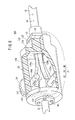
- FIG. 1 is a partially omitted side view of an indwelling device for a blood vessel treatment tool according to an embodiment of the present invention. It is a partially-omission perspective view of the introducer sheath shown in FIG. It is a partially-omission perspective view of the introducer sheath shown in FIG.
- FIG. 2 is a partially omitted vertical sectional view of the introducer sheath shown in FIG. 1.
- FIG. 5 is a cross-sectional view taken along line VV in FIG. 4.
- FIG. 6 is a sectional view taken along line VI-VI in FIG. 4. It is a cross-sectional view of an introducer sheath according to a modification. It is a partially-omission perspective view of the introducer sheath which concerns on another modification.
- the indwelling device 10 for a vascular treatment device shown in FIG. 1 conveys the stent graft 12, which is a vascular treatment device having a self-expanding function, to a target treatment site in the blood vessel.
- the stent graft 12 is composed of a stent formed into a tubular shape by knitting or assembling a metal wire, and a graft composed of a tubular cover coated on the outer periphery of the stent.
- the stent graft 12 can be reduced in diameter by being elastically deformed by a radially inward force.
- the stent graft 12 when the radially inward force is released, the stent graft 12 is self-attacking to be restored to its original size by the elastic force. Has expansion power. That is, the stent graft 12 is configured as a self-expanding stent graft.
- the indwelling device 10 includes an introducer sheath 14 and an inner tube 16, and is used in a state where the inner tube 16 is inserted into the introducer sheath 14 when performing stent graft insertion. It is done.
- the introducer sheath 14 has a sheath body 18 and a hub 20.
- the sheath body 18 functions as an outer tube that houses the stent graft 12 in the inner periphery of the distal end portion.
- the sheath body 18 is made of a material having flexibility (elasticity), and has a lumen having a substantially constant inner diameter along the axial direction. Examples of the material of the sheath body 18 include biocompatible synthetic resins selected from polyamide, polyethylene, fluororesin, polyimide, and the like.
- the hub 20 is a hollow member provided (connected) to the proximal end portion of the sheath body 18, and the hollow portion communicates with the lumen of the sheath body 18. The detailed configuration of the hub 20 will be described later.
- the inner tube 16 is inserted into the introducer sheath 14 so as to be slidable in the axial direction, and has an inner tube main body 22 and a hub 24.
- the inner tube main body 22 is a tubular body that is longer than the sheath main body 18 and has flexibility, and a guide wire lumen 25 for inserting the guide wire is provided along the axial direction.
- the maximum outer diameter of the inner tube body 22 is equal to or smaller than the inner diameter of the sheath body 18 of the introducer sheath 14. For this reason, the inner tube main body 22 can be extracted from the sheath main body 18 and the hub 20.
- An annular groove 26 that functions as an accommodating portion for accommodating the stent graft 12 is formed in the outer peripheral portion near the distal end portion of the inner tube main body 22.
- the stent graft 12 is covered by the sheath body 18 and is prevented from expanding.
- the material of the inner tube 16 include biocompatible synthetic resins selected from polyamide, polyethylene, fluororesin, polyimide, and the like.
- the hub 20 is a hollow member provided (connected) at the proximal end portion of the inner tube 16.
- the indwelling device 10 In order to perform stent graft insertion using the indwelling device 10 configured as described above, the indwelling device 10 in the state shown in FIG. 1 is inserted into the blood vessel along the guide wire previously inserted into the blood vessel. Then, the tip part reaches the target treatment site. Thus, when the distal end portion reaches the target treatment site, the introducer sheath 14 is moved (slid) in the proximal direction with respect to the inner tube 16, and the distal end portion of the sheath body 18 is proximal to the stent graft 12. Shift.
- the stent graft 12 whose expansion has been constrained on the inner peripheral surface of the sheath body 18 until then is expanded by the self-expanding force and is pressed into the blood vessel. Thereby, the stent graft 12 is fixed and placed in the blood vessel.
- the introducer sheath 14 is configured such that the inner tube 16 can be removed, and the effective length of the sheath body 18 (for example, a balloon catheter) can be applied to other treatment devices having a short length (for example, a balloon catheter).
- the length of the sheath body 18 extending from the hub 20 is shortened. 2 to 4, the sheath body 18 is in an initial state where the effective length is not shortened.
- the proximal end portion of the sheath body 18 is inserted into the hub 20 and fixed.
- the base end portion of the sheath body 18 is torn into a plurality (two in the illustrated example), and the respective end pieces 28 a and 28 b are held in the hub 20.
- the hub 20 that holds the proximal end portion of the sheath body 18 is wound inside while tearing the proximal end portion of the sheath body 18, and includes a hub body 31, a cut portion 28, and a plurality of winding shafts. 30 and 32 and an operation unit 34.
- a numbered scale 36 is provided on the outer peripheral surface of the base end portion of the sheath body 18 so that it can be seen how much the effective length of the sheath body 18 has been shortened.
- the scale indicates a length obtained by shortening the sheath body 18 in cooperation with the distal end member 40 described later. This point will be described later.
- the hub body 31 includes a body member 38, a distal end member 40, and a proximal end member 42.
- the body member 38 has a hollow structure. As shown in FIG. 4, the body member 38 is provided with a hollow portion 44, a distal end side opening portion 46, and a proximal end side opening portion 48. 50 is provided. In the hollow portion 44, the proximal end portion of the sheath body 18 is located, and the winding shafts 30 and 32 are disposed.
- the distal end side opening 46 is a cylindrical hole extending from the hollow portion 44 to the distal end side and having substantially the same diameter as the outer shape of the sheath body 18, and the proximal end portion of the sheath body 18 is inserted therethrough.
- the proximal end opening 48 is a cylindrical hole extending from the hollow portion 44 toward the proximal end and having substantially the same diameter as the outer shape of the inner tube 16. In order to insert the inner tube 16, the distal end side opening 46 and the proximal end side opening 48 have the same axis.
- the distal end member 40 is a hollow cylindrical member having an inner diameter substantially the same as the outer shape of the sheath body 18, has a flange portion 52 on the proximal end side, and the flange portion 52 is a screw or the like with respect to the distal end configuration portion 50.
- the fixing parts 51 are fixed.
- the distal end surface of the distal end member 40 has a function of indicating a length obtained by shortening the sheath body 18 in cooperation with the scale 36 provided on the outer peripheral surface of the sheath body 18. That is, when the sheath body 18 is in the initial state, the zero position (the most proximal scale) of the scale 36 coincides with the distal end surface of the distal end member 40.
- a ring-shaped seal member 54 made of an elastic material is disposed between the flange portion 52 of the tip member 40 and the tip constituent portion 50, and the inner peripheral surface of the seal member 54 and the outer peripheral surface of the sheath body 18 are arranged. Is in close contact with the entire circumference. As a result, the inner peripheral surface of the hub main body 31 and the outer peripheral surface of the sheath main body 18 are sealed in a liquid-tight manner at the distal end portion of the hub main body 31.
- the constituent material of the seal member 54 is not particularly limited, and various rubbers such as natural rubber, butyl rubber, isoprene rubber, butadiene rubber, styrene-butadiene rubber, and silicone rubber can be used. Note that the materials listed above can be used as the constituent material of the seal member 54 for the seal members 56, 58, and 60 described later.
- the base end member 42 is a disk-like member having an opening 62 having substantially the same diameter as the outer tube 16 and is fixed to the rear wall 64 of the body member 38 by a fixing component 66 such as a screw.
- a ring-shaped seal member 56 made of an elastic material is disposed between the base end member 42 and the rear wall 64, and the inner peripheral surface of the seal member 56 and the outer peripheral surface of the inner tube 16 extend over the entire circumference. It is in close contact. Thereby, the inner peripheral surface of the hub main body 31 and the outer peripheral surface of the inner tube 16 in the rear end side portion of the hub main body 31 are sealed in a liquid-tight manner.
- a cylindrical guide member 68 is provided in the hollow portion 44 of the body member 38 so that the therapeutic device is smoothly guided to the distal end opening 46 when another therapeutic device is inserted from the proximal end side. Is provided.
- the proximal end portion 68a of the guide member 68 is formed in a flare shape that expands toward the proximal end side so that the distal end of the therapeutic device can be smoothly inserted. In FIG. 2, the guide member 68 is not shown.
- a check valve 70 is provided on the front side of the base end side opening 48 as a valve body for hemostasis.
- This check valve 70 has a plurality of valve bodies 70a divided in the circumferential direction. In FIG. 2, the check valve 70 is not shown.
- the check valve 70 In the state where the inner tube main body 22 is inserted, the check valve 70 is in a valve open state in which the valve body 70a is expanded radially outward as shown by a solid line in FIG. In the extracted state, as shown by the phantom line in FIG. 4, the valve body 70 a is displaced inward in the radial direction and closed.
- the check valve 70 can prevent blood from leaking outside the hub 20 even if the inner tube 16 is removed from the introducer sheath 14 inserted into the blood vessel.
- the constituent materials of the body member 38, the distal end member 40, and the proximal end member 42 are not particularly limited, and various metal materials, various plastics, and the like can be used alone or in combination.
- the cut portion 28 is disposed in the distal end configuration portion 50 that constitutes the distal end side of the hollow portion 44.
- the cut portion 28 forms a cut along the axial direction in the sheath body 18.
- the cut portion 28 in the illustrated example is configured to make a cut at a location on the opposite side of the sheath body 18 in the circumferential direction, that is, a location where the phase in the circumferential direction is shifted by 180 degrees.
- the cut portion 28 includes a plurality of (two in the illustrated example) blades 72 and 74.
- the two blades 72 and 74 are arranged at positions where the sheath body 18 is sandwiched between the blade bodies 72 toward the sheath body 18 side, and the blade body 72 is cut (formed) along the axial direction in the sheath body 18 at each blade edge.
- the constituent material of the blades 72 and 74 is not particularly limited, and for example, various metal materials (stainless steel or the like) can be used. By configuring the blades 72 and 74 with a metal material, it is easy to form a sharp blade edge.
- the body member 38 (the distal end component portion 50) has a plurality (two pieces) of inner ends opened at the inner peripheral surface of the distal end side opening 46 and outer ends opened at the outer surface of the body member 38.
- Through-holes 76 and 78 are formed.
- the through holes 76 and 78 function as slots in which the blades 72 and 74 are accommodated (installed).
- the blades 72 and 74 are inserted from the outer ends of the through holes 76 and 78, and are positioned and fixed in the through holes 76 and 78 by the fixing pins 80 and 82.
- the cutting edges of the blades 72 and 74 protrude from the inner ends of the through holes 76 and 78 (that is, the inner surface of the distal end opening 46) by an amount substantially corresponding to the thickness of the sheath body 18 (thickness of the tube wall). It does not contact the tube body 22. For this reason, when the sheath body 18 moves to the proximal end side, the sheath body 18 is cut in the axial direction by the blades 72 and 74, but the inner tube body 22 is not cut.
- the through holes 76 and 78 in the illustrated example extend in a direction perpendicular to the axis of the distal end opening 46, but may extend in a direction inclined with respect to the axis.
- the configuration for installing and fixing the cutters 72 and 74 to the body member 38 is not limited to the configuration shown in FIG. 5.
- the hollow portion 44 is extended to the distal end side, and the cutters 72 and 74 are installed in the extended portions.
- a structure part to be fixed may be provided.
- the end pieces 28a and 28b of the torn sheath body 18 are fixed to a plurality of (two) winding shafts 30 and 32, respectively.
- the take-up shafts 30 and 32 take up each of the end pieces 28a and 28b of the torn sheath body 18 and are arranged on the base end side of the cut portion 28 in the hub body 31 and rotate around the body member 38. Supported as possible.
- the two winding shafts 30 and 32 in the illustrated example are spaced apart from each other in the dividing direction of the sheath body 18 by the cut (vertical direction in FIGS. 2 and 4). Further, the two winding shafts 30 and 32 are positioned on opposite sides with respect to the axis of the hub 20 (the axis of the distal end side opening 46 and the proximal end side opening 48). The rotation center lines are parallel to each other.
- the winding shafts 30 and 32 are provided with holes 84 and 86 extending in the axial direction and penetrating in the diameter direction, and the end pieces of the sheath body 18 are provided in the holes 84 and 86, respectively.
- 28 a and 28 b are inserted and fixed by a plurality of fixing pins 90 and 92 arranged along the axial direction of the winding shafts 30 and 32.
- the end pieces 28a, 28b of the sheath body 18 may be fixed to the winding shafts 30, 32 by other methods such as adhesion and welding.
- one end portions of the winding shafts 30 and 32 are inserted and supported in bottomed cylindrical holes 95a and 95b provided in one wall portion 94 of the body member 38 of the hub body 31. ing.
- the other end portions of the winding shafts 30 and 32 pass through holes 97 a and 97 b provided in the other wall portion 96 of the body member 38.
- Seal members 58 and 60 made of an elastic material are disposed between the winding shafts 30 and 32 and the holes 97a and 97b, whereby the winding shafts 30 and 32 and the holes 97a and 97b are connected to each other. The space is sealed fluid-tight.
- an operation portion 34 for rotating the take-up shafts 30 and 32 by operating is provided on the outside of the hub body 31.
- the operation unit 34 is configured by two operation wheels 100 and 102 that can be rotated. As shown in FIGS. 3 and 6, a recess 98 having a flat bottom is formed on the side of the hub body 31, and operation wheels 100 and 102 are installed in the recess 98.
- the hub 20 further includes an interlocking mechanism 106 that interlocks the rotations of the winding shafts 30 and 32 with each other.
- the interlocking mechanism 106 includes gears 107 and 108 that are provided on the outer peripheral portions of the operation wheels 100 and 102 and mesh with each other. Thus, by rotating one of the two operation wheels 100 and 102, the other rotates in the opposite direction.
- the introducer sheath 14 configured as described above can be used for other treatment by shortening the effective length of the sheath body 18 after removing the inner tube 16 from the proximal end side after performing stent graft insertion. It can be used as an introducer sheath for a gait device (eg, a balloon catheter).
- a gait device eg, a balloon catheter
- the sheath body 18 can be shortened in total length after being used as an outer tube of the indwelling device 10 used for indwelling the vascular treatment device (stent graft 12). it can. For this reason, it is possible to insert a treatment device shorter than the full length of the original introducer sheath 14 into the blood vessel by using the introducer sheath 14 having a short effective length, and for a treatment longer than necessary. There is no need to use the device.
- each end piece 28 a, 28 b of the sheath body 18 is taken up by the plurality of take-up shafts 30, 32, so that the sheath body 18 is drawn into the hub 20 and at the same time the sheath 28 is cut by the cut portion 28.
- a cut can be made in the body 18. Accordingly, the winding of the sheath body 18 and the formation of the cut are simultaneously performed by rotating the winding shafts 30 and 32. Therefore, the effective length of the sheath body 18 can be easily shortened by one operation (rotation operation). can do.
- the base end portion of the sheath body 18 is cut into two by the cut portion 28, and the distal ends thereof are wound by the two winding shafts 30 and 32 that are separated from each other in the dividing direction of the sheath body 18. Therefore, the sheath body 18 can be smoothly wound up with a small number of parts.
- the introducer sheath 14 by using the sharp blades 72 and 74 as the cut portion 28, it is possible to reduce the cutting resistance when the sheath body 18 is pulled into the hub 20.
- the torque required for winding the end pieces 28a, 28b can be reduced, and the winding operation can be performed more easily.
- each part is liquid-tightly sealed by the seal members 54, 56, 58, 60, so that even if blood flows into the hub 20 through the sheath body 18, the blood is outside the hub 20. There is no leakage.
- FIG. 7 is a cross-sectional view of an introducer sheath 14a according to a modification.
- the introducer sheath 14a according to the modified example will be described.
- the difference from the introducer sheath 14 described above will be mainly described, and description of similar matters will be omitted.
- the introducer sheath 14a shown in FIG. 7 has rotation restriction mechanisms 104 and 105 that prevent the winding shafts 30 and 32 from rotating in the rewinding direction.
- the rotation restricting mechanisms 104 and 105 are configured by one-way clutches 104A and 105A.
- the one-way clutches 104 ⁇ / b> A and 105 ⁇ / b> A have an outer peripheral portion fixed to the body member 38 and an inner peripheral portion fixed to the winding shafts 30 and 32.
- the winding shafts 30 and 32 are interlocked via the gears 107 and 108, so that only one of the one-way clutches 104A and 105A may be provided.
- the rotation regulating mechanisms 104 and 105 prevent the winding shafts 30 and 32 from rotating in the rewinding direction, so that the end piece 28a of the sheath body 18 once wound up, 28b is not rewound, and the sheath body 18 is prevented from moving in the extending direction with respect to the hub 20. For this reason, the cut formed by the cut portion 28 is not exposed to the outside of the hub 20, and blood can be prevented from leaking out of the hub 20 from the cut.
- the configuration of the rotation restricting mechanisms 104 and 105 is not limited to the one-way clutch 104A or 105A, but may be a ratchet mechanism having an engaging portion that engages with at least one of the gears 107 and 108.
- the ratchet mechanism is configured such that when the winding shafts 30 and 32 are in the winding direction, the engaging portion is elastically displaced to overcome the teeth of the gears 107 and 108 and in the direction opposite to the winding direction. Is configured to prevent reverse rotation of the winding shafts 30 and 32 by preventing the engaging portion from getting over the tooth portions of the gears 107 and 108.
- the number of places where the cut portion 28 cuts is not limited to two, and may be three or more. That is, the base end portion of the sheath body 18 may be wound after being torn into three or more. When three or more cuts are made in this way, the number of end pieces formed on the sheath body 18 is the same as the number of cuts.
- the structure which provides the two winding shafts 30 and 32 similarly to the above, and winds up two (2 or more) terminal pieces with the winding shafts 30 and 32 can be employ
- a plurality of winding shafts corresponding to each of the end pieces formed in the same number as the cut lines may be provided, and in this case, the axes (rotation center lines) of the winding shafts may not be parallel to each other.
- FIG. 8 is a partially omitted perspective view of an introducer sheath 14b according to another modification.
- the introducer sheath 14b will be described, but the difference from the introducer sheath 14 described above will be mainly described, and the description of the same matters will be omitted.
- the cut portion 120 for making a plurality of cuts along the axial direction of the sheath body 18 is configured by one or a plurality of wire rods (in the illustrated example, two wire rods 122 and 124). ing.
- the wire rods 122 and 124 are, for example, a wire or a thread.
- two wire rods 122 and 124 are arranged substantially in parallel so as to form four cuts in the sheath body 18 on the distal end side of the hub body 31 with respect to the winding shaft. Yes. For this reason, the proximal end portion of the sheath body 18 is divided into four end pieces 126a to 126d.
- the two wire rods 122 and 124 are fixed to the wall surface 128 on the distal end side of the body member 38 by an appropriate means, and are disposed so as to cross the distal end side opening 46 (see FIG. 4).
- the two wire rods 122 and 124 may be embedded in the distal end component 50 so as to cross the distal end side opening 46 instead of the illustrated arrangement configuration.
- the wire rods 122 and 124 are stretched in a state where an appropriate tension is applied so that the sheath body 18 can be effectively cut when the sheath body 18 is pulled into the hub 20.
- the wire rods 122 and 124 should have a sufficiently small diameter within a range in which strength can be secured in order to reduce cutting resistance when making a cut in the sheath body 18.
- each of the wire rods 122 and 124 is partially interposed between the sheath main body 18 and the inner tube main body 22.
- the two wire rods 122 and 124 are arranged at positions spaced in the axial direction of the winding shafts 30 and 32 so as to extend in a direction substantially orthogonal to the axial direction of the winding shafts 30 and 32. Therefore, as shown in FIG. 8, two of the four end pieces 126a to 126d are divided on both sides of the take-up shafts 30 and 32 in the separation direction, and the remaining two are taken up by the take-up shafts 30 and 32. It is divided on both sides in the axial direction.
- the end pieces 126a and 126c are held (fixed) on the winding shafts 30 and 32, respectively.
- the remaining end pieces 126b and 126d are not fixed to other members or elements in the hollow portion 44 and are free ends.
- the sheath 14b in order to shorten the effective length of the sheath body 18, it is only necessary to perform a rotation operation on the operation portion 34 as in the introducer sheath 14 shown in FIG. That is, when the operation wheels 100 and 102 are rotated, the winding shafts 30 and 32 connected to the operation wheels 100 and 102 are rotated while the sheath body 18 is cut by the wire rods 122 and 124, whereby the winding shaft 30 and The end pieces 126a and 126c are wound up by 32. As a result, the sheath body 18 is drawn into the hub 20 and the effective length is shortened.
- the end pieces 126a and 126c are wound around the winding shafts 30 and 32 as described above, but the other end pieces 126b and 126d are not wound. However, since the end pieces 126b and 126d have flexibility and can be easily deformed when an external force is applied, the hollow portion 44 is formed while the end pieces 126a and 126c are wound by the take-up shafts 30 and 32. When it comes into contact with the inner wall (the inner wall of the body member 38), the hollow portion 44 is deformed. Accordingly, the winding of the end pieces 126a and 126c by the winding shafts 30 and 32 is not hindered.
- the winding shaft for winding the end pieces 126b and 126d is positioned at the distal end side or the proximal end side of the hub main body 31 with respect to the winding shafts 30 and 32, and the axial line of the hub 20 (the distal end side opening 46). And an axis of the base end side opening 48 (see FIG. 4)).
- the winding shaft for winding the end pieces 126b and 126d is rotatably provided on the body member 38 so that the axial direction thereof is perpendicular to the axial direction of the winding shafts 30 and 32.
- the configuration having the two wire rods 122 and 124 is shown as an example of the configuration of the cut portion 120, but as another configuration of the cut portion 120, a single cut may be made in the sheath body 18.
- the rotation restricting mechanisms 104 and 105 shown in FIG. 7 may be provided.
Abstract
A placement device (10) for a blood vessel treatment instrument has an introducer sheath (14) functioning as an outer tube, and also has an inner tube (16). The introducer sheath (14) has a flexible, tube-shaped sheath body (18) and a hub (20) into which the base end of the sheath body (18) is inserted. The hub (20) takes up the base end of the sheath body (18) into the hub (20) by means of winding shafts (30, 32) while tearing the base end of the sheath body (18) by cutting blades (72, 74), and thus the length of extension of the sheath body (18) from the hub (20) can be reduced.
Description
本発明は、全長を短くすることが可能なイントロデューサシース、血管治療具の留置装置、及びイントロデューサシースの短縮方法に関する。
The present invention relates to an introducer sheath, an indwelling device for a vascular treatment device, and a method for shortening the introducer sheath that can shorten the overall length.
一般に診断や治療のために血管内にカテーテルを挿入する際には、体外と血管内を繋ぐアクセスルートとしてイントロデューサシースが用いられる。その第1の目的は、複数のカテーテルを順に用いる際、血管穿刺部を径差のあるカテーテルが複数回抜き差しされることで発生する血管損傷を少なくすることにある。第2の目的は、大径のバルーンカテーテルやバルーン拡張型のステントのように平滑でない表面をもつカテーテルを挿入する際、挿入を容易にするとともに血管損傷を避けることにある。
Generally, when a catheter is inserted into a blood vessel for diagnosis or treatment, an introducer sheath is used as an access route that connects the outside of the body and the inside of the blood vessel. The first purpose is to reduce blood vessel damage that occurs when a catheter having a diameter difference is inserted and removed a plurality of times when a plurality of catheters are used in order. The second object is to facilitate insertion and avoid blood vessel damage when inserting a catheter having a non-smooth surface, such as a large-diameter balloon catheter or a balloon expandable stent.
一方、大動脈瘤の治療のために使用されるステントグラフトシステム(以下、単に「システム」ということがある)の場合には、イントロデューサシースが用いられることは少なく、血管に直接挿入されることが多い。ステントグラフトシステムは、ステントグラフトを動脈瘤のある治療部位まで運び、自己拡張力によって拡径させて留置するステントグラフト内挿術において使用される治療用デバイスであり、そのシャフト外径が一般のカテーテルに比べて格段に太いためである。
On the other hand, in the case of a stent graft system (hereinafter, simply referred to as “system”) used for the treatment of an aortic aneurysm, an introducer sheath is rarely used and is often directly inserted into a blood vessel. . The stent graft system is a therapeutic device used in stent graft insertion that carries the stent graft to the treatment site where the aneurysm is located and expands the diameter by self-expanding force. The outer diameter of the shaft is larger than that of a general catheter. This is because it is much thicker.
一般的なステントグラフトシステムは、ステントグラフトを先端部内周に収容するアウタチューブと、アウタチューブの内側に摺動可能に挿通されたインナチューブとを有し、インナチューブに対してアウタチューブを基端側にスライドさせることで、ステントグラフトを自己拡張力により拡径させて血管内に留置するように構成されている(例えば、特開2005-270395号公報参照)。
A general stent graft system has an outer tube that accommodates the stent graft in the inner periphery of the distal end portion, and an inner tube that is slidably inserted inside the outer tube, and the outer tube is proximal to the inner tube. By sliding the stent graft, the stent graft is expanded in diameter by a self-expanding force and placed in the blood vessel (see, for example, JP-A-2005-270395).
ステントグラフトの多くの製品は、自己拡張型であり、体内に挿入されるシャフト部分の外面は他の自己拡張型ステントのようにステント部分も平滑なチューブ内に収納されているものが多いため、ステントグラフトシステムを血管内に挿入する際にイントロデューサシースを用いなくても、血管損傷の問題は生じない。
Many stent graft products are self-expanding, and the outer surface of the shaft portion inserted into the body is often housed in a smooth tube like other self-expanding stents. Even if the introducer sheath is not used when inserting the system into the blood vessel, the problem of vascular injury does not occur.
しかしながら、ステントグラフト内挿術では、ステントグラフトを留置した後に、延長用グラフトとして別のステントグラフトを追加する場合があり、また、血管への密着をより強固にするためにバルーンカテーテルを挿入する場合があるため、複数回の抜き差しによる血管損傷の問題は依然として残る。
However, in stent graft insertion, after placing the stent graft, another stent graft may be added as an extension graft, and a balloon catheter may be inserted to further strengthen the adhesion to the blood vessel. The problem of vascular damage due to multiple insertions and removals still remains.
このような問題に対処するため、システムのアウタチューブを別の治療デバイスのイントロデューサシースとして用いる方法がある。この方法では、最初のステントグラフトを挿入し留置した後、システムのアウタチューブ(及びガイドワイヤ)を血管内に残し、システムを構成するその他の部品(インナチューブ等)はすべて抜去し、残されたアウタチューブを別の治療用デバイスを挿入する際のイントロデューサシースとして用いる。これにより、追加のステントグラフトやバルーンカテーテルを挿入するときの血管穿刺部の損傷拡大を防ぐ。
In order to deal with such problems, there is a method of using the outer tube of the system as an introducer sheath of another treatment device. In this method, after the initial stent graft is inserted and placed, the outer tube (and guide wire) of the system is left in the blood vessel, all other components (such as the inner tube) constituting the system are removed, and the remaining outer The tube is used as an introducer sheath when inserting another therapeutic device. Thereby, the damage expansion of the blood vessel puncture part when inserting an additional stent graft or a balloon catheter is prevented.
上述した従来技術に係るステントグラフトシステムの多くは、ステントグラフトを実際に留置する位置(深さ)までアウタチューブを挿入する必要があるため、アウタチューブを含むシステム全長は一般的なイントロデューサシースと比べると長い。このため、システムのアウタチューブをそのまま別の治療用デバイスを挿入する際のイントロデューサシースとして用いる場合は、そのような治療用デバイスは、アウタチューブの全長以上の全長を有することが必要であり、全長が短い治療用デバイスは使用することができない。また、必要以上に長い治療用デバイスは操作が難しくなる。
Many of the above-mentioned conventional stent graft systems require insertion of the outer tube to a position (depth) where the stent graft is actually placed, so that the total length of the system including the outer tube is smaller than that of a general introducer sheath. long. For this reason, when the outer tube of the system is used as an introducer sheath when another therapeutic device is inserted as it is, such a therapeutic device needs to have a total length equal to or greater than the total length of the outer tube, A therapeutic device with a short overall length cannot be used. Also, treatment devices that are longer than necessary are difficult to operate.
本発明は、上記の事情に鑑みてなされたものであり、短い治療用デバイスのイントロデューサシースとして用いることが可能であり、また、必要以上に長い治療用デバイスを使用する必要がないイントロデューサシース、血管治療具の留置装置、及びイントロデューサシースの短縮方法を提供することを目的とする。
The present invention has been made in view of the above circumstances, and can be used as an introducer sheath for a short treatment device, and it is not necessary to use a treatment device longer than necessary. An object of the present invention is to provide an indwelling device for a vascular treatment tool and a method for shortening an introducer sheath.
上記の目的を達成するため、本発明は、長尺シャフトが挿通されるイントロデューサシースであって、可撓性を有するチューブ状のシース本体と、前記シース本体の基端部が挿入されたハブとを備え、前記ハブは、前記シース本体の基端部を引き裂きながら前記ハブ内部に巻き取り、前記シース本体の前記ハブからの延出長を短くできるように構成されていることを特徴とする。
In order to achieve the above object, the present invention provides an introducer sheath through which a long shaft is inserted, and a tubular sheath body having flexibility, and a hub into which a proximal end portion of the sheath body is inserted. The hub is configured to be wound inside the hub while tearing the base end portion of the sheath body, and to shorten the extension length of the sheath body from the hub. .
上記の構成によれば、血管治療具(ステントグラフト)を留置するために使用する血管治療具の留置装置のアウタチューブとしてイントロデューサシースを用いた後に、そのシース本体の全長を短くすることができる。このため、元のイントロデューサシースの全長よりも短い治療用デバイスを、当該イントロデューサシースを利用して血管に挿入することが可能であり、また、必要以上に長い治療用デバイスを使用する必要がない。
According to the above configuration, the introducer sheath can be used as an outer tube of an indwelling device for a vascular treatment device used to place a vascular treatment device (stent graft), and then the entire length of the sheath body can be shortened. For this reason, it is possible to insert a therapeutic device shorter than the entire length of the original introducer sheath into the blood vessel using the introducer sheath, and it is necessary to use a therapeutic device longer than necessary. Absent.
上記のイントロデューサシースにおいて、前記ハブは、前記シース本体に軸線方向に沿った切れ目を形成するカット部と、前記切れ目によって裂かれた前記シース本体の末端片の各々を巻き取る複数の巻取り軸とを有するとよい。
In the introducer sheath described above, the hub includes a plurality of winding shafts that wind each of a cut portion that forms a cut along the axial direction in the sheath main body and a terminal piece of the sheath main body that is torn by the cut. It is good to have.
上記の構成によれば、シース本体の各末端部を複数の巻取り軸によって巻き取ることで、シース本体をハブ内に引き込むのと同時にカット部によりシース本体に切り込みを入れることができる。従って、巻取り軸を回転させることによって、シース本体の巻取りと切れ目の形成を同時並行的に行うので、1つの操作(回転操作)で容易にシース本体の有効長を短くすることができる。
According to the above configuration, by winding each end portion of the sheath body with the plurality of winding shafts, the sheath body can be drawn into the hub and simultaneously cut into the sheath body by the cut portion. Therefore, since the winding of the sheath body and the formation of the cut are performed simultaneously by rotating the winding shaft, the effective length of the sheath body can be easily shortened by one operation (rotating operation).
上記のイントロデューサシースにおいて、前記カット部は、前記シース本体の周方向の互いに反対側の箇所に切れ目を入れるように構成され、前記複数の巻取り軸は、前記切れ目による前記シース本体の分断方向に離間して配置された2つの巻取り軸であるとよい。
In the introducer sheath described above, the cut portion is configured to make a cut at positions opposite to each other in the circumferential direction of the sheath body, and the plurality of winding shafts are divided in the sheath body by the cut. It is good to be two winding shafts spaced apart from each other.
上記の構成によれば、シース本体の基端部がカット部により2つに切り裂かれ、それらの末端をシース本体の分断方向に互いに離間した2つの巻取り軸により巻き取るので、少ない部品点数でスムーズにシース本体を巻き取ることが可能である。
According to the above configuration, the base end portion of the sheath body is cut into two by the cut portion, and the ends thereof are wound by the two winding shafts separated from each other in the dividing direction of the sheath body. It is possible to smoothly wind up the sheath body.
上記のイントロデューサシースにおいて、前記カット部は、前記シース本体の周方向の異なる箇所に切れ目を入れる複数の刃物を有するとよい。
In the introducer sheath described above, the cut portion may have a plurality of blades that make cuts at different locations in the circumferential direction of the sheath body.
上記の構成によれば、カット部として鋭利な刃物を用いることで、シース本体をハブ内に引き込む際の切断抵抗を小さくすることができ、これにより、シース本体の末端部を巻き取る際に要するトルクを小さくすることができ、巻取り操作をより容易に行うことが可能となる。
According to said structure, by using a sharp blade as a cut part, the cutting | disconnection resistance at the time of drawing in a sheath main body in a hub can be made small, and this is required when winding up the terminal part of a sheath main body. The torque can be reduced and the winding operation can be performed more easily.
上記のイントロデューサシースにおいて、前記ハブは、前記複数の巻取り軸を互いに連動して回転させる連動機構をさらに有するとよい。
In the introducer sheath, the hub may further include an interlocking mechanism that rotates the plurality of winding shafts in conjunction with each other.
上記の構成によれば、全ての巻取り軸が同時に回転するので、引き裂かれた各末端部をバランスよく巻き取ることが可能である。
According to the above configuration, since all the winding shafts rotate at the same time, it is possible to wind up each torn end portion with a good balance.
上記のイントロデューサシースにおいて、前記ハブは、前記巻取り軸の巻き戻し方向の回転を阻止する回転規制機構を有するとよい。
In the introducer sheath described above, the hub may have a rotation restricting mechanism that prevents the winding shaft from rotating in the rewinding direction.
上記の構成によれば、一旦巻き取ったシース本体の末端部を巻き戻す方向に巻取り軸が回転することがないので、シース本体がハブに対して延出する方向に移動すること阻止される。このため、カット部により形成された切れ目がハブの外部に露出することがなく、切れ目からハブの外部に血液が漏れ出ることを未然に防止することができる。
According to said structure, since a winding shaft does not rotate in the direction which rewinds the terminal part of the sheath main body once wound up, it is prevented that a sheath main body moves to the direction extended with respect to a hub. . For this reason, the cut formed by the cut portion is not exposed to the outside of the hub, and blood can be prevented from leaking from the cut to the outside of the hub.
上記のイントロデューサシースにおいて、前記ハブは、前記巻取り軸及び前記シース本体の基端部が収容される中空部が設けられたハブ本体と、前記ハブ本体の外部から回転操作することで、前記巻取り軸を回転させる回転操作部とを有し、前記ハブ本体は、前記シース本体を介して内部に流入した液体が外部に漏れ出ないように液密に構成されているとよい。
In the introducer sheath, the hub is configured to rotate from the outside of the hub body, and a hub body provided with a hollow portion in which the winding shaft and a base end portion of the sheath body are accommodated. It is preferable that the hub main body is configured to be liquid-tight so that the liquid flowing into the inside through the sheath main body does not leak to the outside.
上記の構成によれば、シース本体を介してハブ内に血液が流入しても、血液がハブの外部に漏れ出ることがない。
According to the above configuration, even if blood flows into the hub through the sheath body, the blood does not leak out of the hub.
また、本発明は、自己拡張機能を有する血管治療具を血管内の目的の治療箇所まで搬送し、留置する血管治療具の留置装置であって、前記血管治療具を先端部内周に収容するシース本体を有するイントロデューサシースと、前記シース本体の内側に摺動可能に挿通されるインナチューブを備え、前記イントロデューサシースは、可撓性を有するチューブ状のシース本体と、前記シース本体の基端部が挿入されたハブとを備え、前記ハブは、前記シース本体の基端部を引き裂きながら前記ハブ内部に巻き取り、前記シース本体の前記ハブからの延出長を短くできるように構成されていることを特徴とする。
The present invention also relates to an indwelling device for a vascular treatment device for transporting and placing a vascular treatment device having a self-expanding function to a target treatment site in the blood vessel, wherein the sheath accommodates the vascular treatment device in the inner periphery of the distal end portion. An introducer sheath having a main body, and an inner tube slidably inserted inside the sheath main body, the introducer sheath comprising a flexible tubular sheath main body and a proximal end of the sheath main body And a hub inserted into the hub while tearing the proximal end of the sheath body, and the extension length of the sheath body from the hub can be shortened. It is characterized by being.
上記の構成によれば、血管治療具を留置した後、インナチューブをシース本体から抜去し、シース本体の有効長を短くすることで、元のイントロデューサシースの全長よりも短い治療用デバイスのイントロデューサシースとして用いることが可能となり、また、必要以上に長い治療用デバイスを使用する必要がない。
According to the above configuration, after placing the vascular treatment device, the inner tube is removed from the sheath body, and the effective length of the sheath body is shortened, so that the intro of the treatment device shorter than the entire length of the original introducer sheath is obtained. It can be used as a deuce sheath, and it is not necessary to use a therapeutic device that is longer than necessary.
また、本発明は、長尺シャフトが挿通されるイントロデューサシースの短縮方法であって、シース本体の基端部を引き裂き、前記シース本体の基端部が挿入されたハブ内に前記シースを引き込み、引き裂かれた前記シース本体の末端片を巻き取ることを特徴とする。
The present invention also relates to a method for shortening an introducer sheath through which a long shaft is inserted, in which a proximal end portion of the sheath body is torn and the sheath is retracted into a hub into which the proximal end portion of the sheath body is inserted. The wound end piece of the sheath body is wound up.
以下、本発明に係るイントロデューサシース、血管治療具の留置装置、及びイントロデューサシースの短縮方法について好適な実施の形態を挙げ、添付の図面を参照しながら説明する。なお、説明の都合上、図1、図4、図5中の右側を「先端」、左側を「基端(後端)」といい、図2中の右上側を「先端」、左下側を「基端(後端)」といい、図3中の左下側を「先端」、右上側を「基端(後端)」という。
Hereinafter, preferred embodiments of an introducer sheath, an indwelling device for a blood vessel treatment device, and a method for shortening an introducer sheath according to the present invention will be described with reference to the accompanying drawings. For convenience of explanation, the right side in FIGS. 1, 4 and 5 is referred to as “tip”, the left side is referred to as “base end (rear end)”, the upper right side in FIG. The lower left side in FIG. 3 is referred to as “front end”, and the upper right side is referred to as “base end (rear end)”.
図1に示す血管治療具の留置装置10(以下、単に「留置装置10」ともいう)は、自己拡張機能を有する血管治療具であるステントグラフト12を血管内の目的の治療箇所まで搬送し、留置するものである。ステントグラフト12は、金属の線材を編み、あるいは組んで、筒状に形成してなるステントと、このステントの外周に被覆された筒状のカバーからなるグラフトとで構成されるものである。ステントグラフト12は、半径方向内方への力により弾性変形することで縮径可能である一方、半径方向内方への力が解除されると、弾性力により元の大きさに復元しようとする自己拡張力を有している。すなわち、ステントグラフト12は、自己拡張型ステントグラフトとして構成されている。
The indwelling device 10 for a vascular treatment device shown in FIG. 1 (hereinafter also simply referred to as “indwelling device 10”) conveys the stent graft 12, which is a vascular treatment device having a self-expanding function, to a target treatment site in the blood vessel. To do. The stent graft 12 is composed of a stent formed into a tubular shape by knitting or assembling a metal wire, and a graft composed of a tubular cover coated on the outer periphery of the stent. The stent graft 12 can be reduced in diameter by being elastically deformed by a radially inward force. On the other hand, when the radially inward force is released, the stent graft 12 is self-attacking to be restored to its original size by the elastic force. Has expansion power. That is, the stent graft 12 is configured as a self-expanding stent graft.
図1示すように、この留置装置10は、イントロデューサシース14とインナチューブ16とを有し、ステントグラフト内挿術を行う際には、イントロデューサシース14内にインナチューブ16を挿通した状態で用いられる。
As shown in FIG. 1, the indwelling device 10 includes an introducer sheath 14 and an inner tube 16, and is used in a state where the inner tube 16 is inserted into the introducer sheath 14 when performing stent graft insertion. It is done.
イントロデューサシース14は、シース本体18と、ハブ20とを有する。シース本体18は、ステントグラフト12を先端部内周に収容するアウタチューブとして機能するものである。シース本体18は、可撓性(弾性)を有する材料により構成され、軸線方向に沿ってほぼ一定内径の内腔を有する。シース本体18の材質としては、例えば、ポリアミド、ポリエチレン、フッ素樹脂、ポリイミド等から選ばれた生体適合性のある合成樹脂が挙げられる。
The introducer sheath 14 has a sheath body 18 and a hub 20. The sheath body 18 functions as an outer tube that houses the stent graft 12 in the inner periphery of the distal end portion. The sheath body 18 is made of a material having flexibility (elasticity), and has a lumen having a substantially constant inner diameter along the axial direction. Examples of the material of the sheath body 18 include biocompatible synthetic resins selected from polyamide, polyethylene, fluororesin, polyimide, and the like.
ハブ20は、シース本体18の基端部に設けられた(接続された)中空状の部材であり、その中空部はシース本体18の内腔と連通している。なお、ハブ20の詳細な構成については後述する。
The hub 20 is a hollow member provided (connected) to the proximal end portion of the sheath body 18, and the hollow portion communicates with the lumen of the sheath body 18. The detailed configuration of the hub 20 will be described later.
インナチューブ16は、イントロデューサシース14に対し軸線方向に摺動可能に挿通されるものであり、インナチューブ本体22と、ハブ24とを有する。インナチューブ本体22は、シース本体18よりも長尺な可撓性を有する管状体であり、ガイドワイヤを挿通するためのガイドワイヤルーメン25が軸線方向に沿って設けられている。インナチューブ本体22の最大外径は、イントロデューサシース14のシース本体18の内径以下である。このため、インナチューブ本体22は、シース本体18及びハブ20から抜去することができる。
The inner tube 16 is inserted into the introducer sheath 14 so as to be slidable in the axial direction, and has an inner tube main body 22 and a hub 24. The inner tube main body 22 is a tubular body that is longer than the sheath main body 18 and has flexibility, and a guide wire lumen 25 for inserting the guide wire is provided along the axial direction. The maximum outer diameter of the inner tube body 22 is equal to or smaller than the inner diameter of the sheath body 18 of the introducer sheath 14. For this reason, the inner tube main body 22 can be extracted from the sheath main body 18 and the hub 20.
インナチューブ本体22の先端部近傍の外周部には、ステントグラフト12を収容するための収容部として機能する環状溝26が形成されている。図1では、ステントグラフト12は、シース本体18によって覆われているため拡張が阻止されている。インナチューブ16の材質としては、例えば、ポリアミド、ポリエチレン、フッ素樹脂、ポリイミド等から選ばれた生体適合性のある合成樹脂が挙げられる。ハブ20は、インナチューブ16の基端部に設けられた(接続された)中空状の部材である。
An annular groove 26 that functions as an accommodating portion for accommodating the stent graft 12 is formed in the outer peripheral portion near the distal end portion of the inner tube main body 22. In FIG. 1, the stent graft 12 is covered by the sheath body 18 and is prevented from expanding. Examples of the material of the inner tube 16 include biocompatible synthetic resins selected from polyamide, polyethylene, fluororesin, polyimide, and the like. The hub 20 is a hollow member provided (connected) at the proximal end portion of the inner tube 16.
上記のように構成された留置装置10を用いてステントグラフト内挿術を行うには、先行して血管内に挿入されたガイドワイヤに沿って図1に示す状態の留置装置10を血管内に挿入していき、先端部を目的の治療部位に到達させる。こうして、先端部を目的の治療部位に到達させたら、イントロデューサシース14をインナチューブ16に対して基端方向に移動(スライド)させ、シース本体18の先端部をステントグラフト12よりも基端側にずらす。すると、それまでシース本体18の内周面で拡張が拘束されていたステントグラフト12は、自己拡張力によって拡張して血管内に圧接される。これにより、ステントグラフト12は、血管内に固定され留置される。
In order to perform stent graft insertion using the indwelling device 10 configured as described above, the indwelling device 10 in the state shown in FIG. 1 is inserted into the blood vessel along the guide wire previously inserted into the blood vessel. Then, the tip part reaches the target treatment site. Thus, when the distal end portion reaches the target treatment site, the introducer sheath 14 is moved (slid) in the proximal direction with respect to the inner tube 16, and the distal end portion of the sheath body 18 is proximal to the stent graft 12. Shift. Then, the stent graft 12 whose expansion has been constrained on the inner peripheral surface of the sheath body 18 until then is expanded by the self-expanding force and is pressed into the blood vessel. Thereby, the stent graft 12 is fixed and placed in the blood vessel.
イントロデューサシース14は、インナチューブ16を抜去できるように構成され、さらに、長さの短い他の治療デバイス(例えば、バルーンカテーテル等)に対しても適用できるように、シース本体18の有効長(シース本体18のハブ20からの延出長)を短くできるように構成されている。図2~図4において、シース本体18は、有効長が短くされていない初期状態である。
The introducer sheath 14 is configured such that the inner tube 16 can be removed, and the effective length of the sheath body 18 (for example, a balloon catheter) can be applied to other treatment devices having a short length (for example, a balloon catheter). The length of the sheath body 18 extending from the hub 20 is shortened. 2 to 4, the sheath body 18 is in an initial state where the effective length is not shortened.
図2に示すように、シース本体18の基端部は、ハブ20内に挿入され固定されている。シース本体18の基端部は、複数(図示例で2つ)に引き裂かれて、その各末端片28a、28bがハブ20内で保持されている。このようなシース本体18の基端部を保持するハブ20は、シース本体18の基端部を引き裂きながら内部に巻き取るものであり、ハブ本体31と、カット部28と、複数の巻取り軸30、32と、操作部34とを有する。
2, the proximal end portion of the sheath body 18 is inserted into the hub 20 and fixed. The base end portion of the sheath body 18 is torn into a plurality (two in the illustrated example), and the respective end pieces 28 a and 28 b are held in the hub 20. The hub 20 that holds the proximal end portion of the sheath body 18 is wound inside while tearing the proximal end portion of the sheath body 18, and includes a hub body 31, a cut portion 28, and a plurality of winding shafts. 30 and 32 and an operation unit 34.
シース本体18の有効長をどれだけ短くしたのかが分かるように、シース本体18の基端部の外周面には、数字付きの目盛り36が設けられている。目盛りは、後述する先端部材40と協働して、シース本体18を短くした長さを示すようになっている。この点については後述する。
A numbered scale 36 is provided on the outer peripheral surface of the base end portion of the sheath body 18 so that it can be seen how much the effective length of the sheath body 18 has been shortened. The scale indicates a length obtained by shortening the sheath body 18 in cooperation with the distal end member 40 described later. This point will be described later.
ハブ本体31は、胴体部材38と、先端部材40と、基端部材42とを有する。胴体部材38は、中空構造に構成されている。図4に示すように、胴体部材38には、中空部44と、先端側開口部46と、基端側開口部48とが設けられ、さらに、中空部44よりも先端側には先端構成部50が設けられている。中空部44には、シース本体18の基端部が位置するとともに、巻取り軸30、32が配置されている。
The hub body 31 includes a body member 38, a distal end member 40, and a proximal end member 42. The body member 38 has a hollow structure. As shown in FIG. 4, the body member 38 is provided with a hollow portion 44, a distal end side opening portion 46, and a proximal end side opening portion 48. 50 is provided. In the hollow portion 44, the proximal end portion of the sheath body 18 is located, and the winding shafts 30 and 32 are disposed.
先端側開口部46は、中空部44から先端側に延在する、シース本体18の外形とほぼ同径の円筒形の孔であり、シース本体18の基端部が挿通されている。基端側開口部48は、中空部44から基端側に延在する、インナチューブ16の外形とほぼ同径の円筒形の孔である。インナチューブ16を挿通させるため、先端側開口部46と基端側開口部48とは、軸線が同一となっている。
The distal end side opening 46 is a cylindrical hole extending from the hollow portion 44 to the distal end side and having substantially the same diameter as the outer shape of the sheath body 18, and the proximal end portion of the sheath body 18 is inserted therethrough. The proximal end opening 48 is a cylindrical hole extending from the hollow portion 44 toward the proximal end and having substantially the same diameter as the outer shape of the inner tube 16. In order to insert the inner tube 16, the distal end side opening 46 and the proximal end side opening 48 have the same axis.
先端部材40は、シース本体18の外形とほぼ同径の内径を有する中空円筒形の部材であり、基端側にフランジ部52を有し、フランジ部52が先端構成部50に対してネジ等の固定部品51により固定されている。
The distal end member 40 is a hollow cylindrical member having an inner diameter substantially the same as the outer shape of the sheath body 18, has a flange portion 52 on the proximal end side, and the flange portion 52 is a screw or the like with respect to the distal end configuration portion 50. The fixing parts 51 are fixed.
先端部材40の先端面は、シース本体18の外周面に付された目盛り36と協働して、シース本体18を短くした長さを示す機能を有する。すなわち、シース本体18が初期状態のとき、目盛り36のゼロ位置(最も基端側の目盛り)が先端部材40の先端面と一致する。
The distal end surface of the distal end member 40 has a function of indicating a length obtained by shortening the sheath body 18 in cooperation with the scale 36 provided on the outer peripheral surface of the sheath body 18. That is, when the sheath body 18 is in the initial state, the zero position (the most proximal scale) of the scale 36 coincides with the distal end surface of the distal end member 40.
先端部材40のフランジ部52と、先端構成部50との間には、弾性材料で構成されたリング状のシール部材54が配置され、シール部材54の内周面とシース本体18の外周面とが全周にわたって密着している。これにより、ハブ本体31の先端側部分における、ハブ本体31の内周面とシース本体18の外周面とが液密にシールされている。
A ring-shaped seal member 54 made of an elastic material is disposed between the flange portion 52 of the tip member 40 and the tip constituent portion 50, and the inner peripheral surface of the seal member 54 and the outer peripheral surface of the sheath body 18 are arranged. Is in close contact with the entire circumference. As a result, the inner peripheral surface of the hub main body 31 and the outer peripheral surface of the sheath main body 18 are sealed in a liquid-tight manner at the distal end portion of the hub main body 31.
シール部材54の構成材料としては、特に限定されないが、例えば、天然ゴム、ブチルゴム、イソプレンゴム、ブタジエンゴム、スチレン-ブタジエンゴム、シリコーンゴムのような各種ゴムを用いることができる。なお、後述するシール部材56、58、60についても、シール部材54の構成材料として上記に挙げた材料を用いることができる。
The constituent material of the seal member 54 is not particularly limited, and various rubbers such as natural rubber, butyl rubber, isoprene rubber, butadiene rubber, styrene-butadiene rubber, and silicone rubber can be used. Note that the materials listed above can be used as the constituent material of the seal member 54 for the seal members 56, 58, and 60 described later.
基端部材42は、インナチューブ16の外形とほぼ同径の開口部62を有する円盤状の部材であり、胴体部材38の後部壁64に対してネジ等の固定部品66により固定されている。基端部材42と、後部壁64との間には、弾性材料で構成されたリング状のシール部材56が配置され、シール部材56の内周面とインナチューブ16の外周面とが全周にわたって密着している。これにより、ハブ本体31の後端側部分における、ハブ本体31の内周面とインナチューブ16の外周面とが液密にシールされている。
The base end member 42 is a disk-like member having an opening 62 having substantially the same diameter as the outer tube 16 and is fixed to the rear wall 64 of the body member 38 by a fixing component 66 such as a screw. A ring-shaped seal member 56 made of an elastic material is disposed between the base end member 42 and the rear wall 64, and the inner peripheral surface of the seal member 56 and the outer peripheral surface of the inner tube 16 extend over the entire circumference. It is in close contact. Thereby, the inner peripheral surface of the hub main body 31 and the outer peripheral surface of the inner tube 16 in the rear end side portion of the hub main body 31 are sealed in a liquid-tight manner.
他の治療用デバイスを基端側から挿入する際に、治療用デバイスが先端側開口部46にスムーズに案内されるように、胴体部材38の中空部44には、筒状のガイド部材68が設けられている。このガイド部材68の基端部68aは、治療用デバイスの先端がスムーズに挿入されるように基端側に向かって広がるフレア形状に形成されている。なお、図2では、ガイド部材68の図示を省略している。
A cylindrical guide member 68 is provided in the hollow portion 44 of the body member 38 so that the therapeutic device is smoothly guided to the distal end opening 46 when another therapeutic device is inserted from the proximal end side. Is provided. The proximal end portion 68a of the guide member 68 is formed in a flare shape that expands toward the proximal end side so that the distal end of the therapeutic device can be smoothly inserted. In FIG. 2, the guide member 68 is not shown.
イントロデューサシース14を血管内に挿入した状態で、イントロデューサシース14からインナチューブ16を抜去すると、シース本体18を介して中空部44に血液が流入する。そこで、図4に示すように、基端側開口部48の前側には、止血用の弁体として逆止弁70を設けている。この逆止弁70は、周方向に分割された複数の弁体70aを有している。なお、図2では、逆止弁70の図示を省略している。
When the inner tube 16 is removed from the introducer sheath 14 with the introducer sheath 14 inserted into the blood vessel, blood flows into the hollow portion 44 via the sheath body 18. Therefore, as shown in FIG. 4, a check valve 70 is provided on the front side of the base end side opening 48 as a valve body for hemostasis. This check valve 70 has a plurality of valve bodies 70a divided in the circumferential direction. In FIG. 2, the check valve 70 is not shown.
逆止弁70は、インナチューブ本体22が挿通された状態では、図4において実線で示すように、弁体70aが半径方向外方に広げられた開弁状態となるが、インナチューブ本体22が抜去された状態では、図4において仮想線で示すように、弁体70aが半径方向内方に変位して閉塞した弁閉状態となる。この逆止弁70により、血管内に挿入したイントロデューサシース14からインナチューブ16を抜去しても、ハブ20の外側に血液が漏れ出ることを防止できる。
In the state where the inner tube main body 22 is inserted, the check valve 70 is in a valve open state in which the valve body 70a is expanded radially outward as shown by a solid line in FIG. In the extracted state, as shown by the phantom line in FIG. 4, the valve body 70 a is displaced inward in the radial direction and closed. The check valve 70 can prevent blood from leaking outside the hub 20 even if the inner tube 16 is removed from the introducer sheath 14 inserted into the blood vessel.
胴体部材38、先端部材40及び基端部材42の構成材料としては、特に限定されず、例えば、各種金属材料や各種プラスチック等を単独又は組み合わせて用いることができる。
The constituent materials of the body member 38, the distal end member 40, and the proximal end member 42 are not particularly limited, and various metal materials, various plastics, and the like can be used alone or in combination.
図2及び図5に示すように、胴体部材38において、中空部44よりも先端側を構成する先端構成部50には、カット部28が配置されている。カット部28は、シース本体18に軸線方向に沿った切れ目を形成するものである。図示例のカット部28は、シース本体18の周方向の互いに反対側の箇所、すなわち周方向の位相が180度ずれた箇所に切れ目を入れるように構成されている。具体的には、カット部28は、複数(図示例では2つ)の刃物72、74を有している。
As shown in FIGS. 2 and 5, in the body member 38, the cut portion 28 is disposed in the distal end configuration portion 50 that constitutes the distal end side of the hollow portion 44. The cut portion 28 forms a cut along the axial direction in the sheath body 18. The cut portion 28 in the illustrated example is configured to make a cut at a location on the opposite side of the sheath body 18 in the circumferential direction, that is, a location where the phase in the circumferential direction is shifted by 180 degrees. Specifically, the cut portion 28 includes a plurality of (two in the illustrated example) blades 72 and 74.
2つの刃物72、74は、シース本体18を間に挟んだ位置に、刃先をシース本体18側に向けて配置され、各刃先でシース本体18に軸線方向に沿った切れ目を入れる(形成する)。このような刃物72、74の構成材料としては、特に限定されず、例えば、各種金属材料(ステンレス等)を用いることができる。刃物72、74を金属材料により構成することにより、鋭利な刃先を形成しやすい。
The two blades 72 and 74 are arranged at positions where the sheath body 18 is sandwiched between the blade bodies 72 toward the sheath body 18 side, and the blade body 72 is cut (formed) along the axial direction in the sheath body 18 at each blade edge. . The constituent material of the blades 72 and 74 is not particularly limited, and for example, various metal materials (stainless steel or the like) can be used. By configuring the blades 72 and 74 with a metal material, it is easy to form a sharp blade edge.
図5に示すように、胴体部材38(先端構成部50)には、内端が先端側開口部46の内周面で開口し、外端が胴体部材38の外面で開口する複数(2つ)の貫通孔76、78が形成されている。貫通孔76、78は、刃物72、74が収容(設置)されるスロットとして機能するものである。刃物72、74は、貫通孔76、78の外端から挿入され、固定ピン80、82により貫通孔76、78内で位置決めされて固定されている。
As shown in FIG. 5, the body member 38 (the distal end component portion 50) has a plurality (two pieces) of inner ends opened at the inner peripheral surface of the distal end side opening 46 and outer ends opened at the outer surface of the body member 38. ) Through- holes 76 and 78 are formed. The through holes 76 and 78 function as slots in which the blades 72 and 74 are accommodated (installed). The blades 72 and 74 are inserted from the outer ends of the through holes 76 and 78, and are positioned and fixed in the through holes 76 and 78 by the fixing pins 80 and 82.
刃物72、74の刃先は、貫通孔76、78の内端(すなわち、先端側開口部46の内面)からシース本体18の肉厚(管壁の厚さ)に略相当する分だけ突出し、インナチューブ本体22には接触していない。このため、シース本体18が基端側に移動した際、シース本体18は、刃物72、74によって軸線方向に切断されるが、インナチューブ本体22には切り込みが入らない。
The cutting edges of the blades 72 and 74 protrude from the inner ends of the through holes 76 and 78 (that is, the inner surface of the distal end opening 46) by an amount substantially corresponding to the thickness of the sheath body 18 (thickness of the tube wall). It does not contact the tube body 22. For this reason, when the sheath body 18 moves to the proximal end side, the sheath body 18 is cut in the axial direction by the blades 72 and 74, but the inner tube body 22 is not cut.
このように、刃物72、74は、貫通孔76、78に挿入及び固定されて位置決めされているので、先端側開口部46の内周面からの刃先の突出量を正確に設定し、かつその状態を確実に保持できる。なお、図示例の各貫通孔76、78は、先端側開口部46の軸線に対して直交する方向に延在しているが、当該軸線に対して傾斜する方向に延在してもよい。
Thus, since the blades 72 and 74 are inserted and fixed in the through holes 76 and 78 and positioned, the amount of protrusion of the blade edge from the inner peripheral surface of the distal end side opening 46 is accurately set, and The state can be reliably maintained. The through holes 76 and 78 in the illustrated example extend in a direction perpendicular to the axis of the distal end opening 46, but may extend in a direction inclined with respect to the axis.
刃物72、74を胴体部材38に設置及び固定するための構成は、図5に示す構成に限られず、例えば、中空部44を先端側に延長し、その延長した部分に刃物72、74を設置及び固定する構造部を設けてもよい。
The configuration for installing and fixing the cutters 72 and 74 to the body member 38 is not limited to the configuration shown in FIG. 5. For example, the hollow portion 44 is extended to the distal end side, and the cutters 72 and 74 are installed in the extended portions. In addition, a structure part to be fixed may be provided.
図2及び図4に示すように、引き裂かれたシース本体18の末端片28a、28bは、それぞれ複数(2つ)の巻取り軸30、32に固定されている。巻取り軸30、32は、裂かれたシース本体18の末端片28a、28bの各々を巻き取るものであり、ハブ本体31においてカット部28よりも基端側に配置され、胴体部材38に回転可能に支持されている。
As shown in FIGS. 2 and 4, the end pieces 28a and 28b of the torn sheath body 18 are fixed to a plurality of (two) winding shafts 30 and 32, respectively. The take-up shafts 30 and 32 take up each of the end pieces 28a and 28b of the torn sheath body 18 and are arranged on the base end side of the cut portion 28 in the hub body 31 and rotate around the body member 38. Supported as possible.
図示例の2つの巻取り軸30、32は、切れ目によるシース本体18の分断方向(図2及び図4で上下方向)に離間して配置されている。また、2つの巻取り軸30、32は、ハブ20の軸線(先端側開口部46及び基端側開口部48の軸線)を基準として互いに反対側に位置しており、さらに、それらの軸線(回転中心線)は、互いに平行である。
The two winding shafts 30 and 32 in the illustrated example are spaced apart from each other in the dividing direction of the sheath body 18 by the cut (vertical direction in FIGS. 2 and 4). Further, the two winding shafts 30 and 32 are positioned on opposite sides with respect to the axis of the hub 20 (the axis of the distal end side opening 46 and the proximal end side opening 48). The rotation center lines are parallel to each other.
図6に示すように、巻取り軸30、32には、軸線方向に沿って延び、直径方向に貫通する孔部84、86が設けられ、その孔部84、86にシース本体18の末端片28a、28bが挿入され、巻取り軸30、32の軸線方向に沿って並んだ複数の固定ピン90、92により固定されている。なお、巻取り軸30、32に対するシース本体18の末端片28a、28bの固定は、接着、溶着等の他の方法で行ってもよい。
As shown in FIG. 6, the winding shafts 30 and 32 are provided with holes 84 and 86 extending in the axial direction and penetrating in the diameter direction, and the end pieces of the sheath body 18 are provided in the holes 84 and 86, respectively. 28 a and 28 b are inserted and fixed by a plurality of fixing pins 90 and 92 arranged along the axial direction of the winding shafts 30 and 32. The end pieces 28a, 28b of the sheath body 18 may be fixed to the winding shafts 30, 32 by other methods such as adhesion and welding.
図6に示すように、巻取り軸30、32の一端部は、ハブ本体31の胴体部材38の一方の壁部94に設けられた有底円筒状の穴部95a、95bに挿入及び支持されている。巻取り軸30、32の他端部は、胴体部材38の他方の壁部96に設けられた孔部97a、97bを貫通している。巻取り軸30、32と孔部97a、97bとの間には、弾性材料で構成されたシール部材58、60が配置され、これにより、巻取り軸30、32と孔部97a、97bとの間が液密にシールされている。
As shown in FIG. 6, one end portions of the winding shafts 30 and 32 are inserted and supported in bottomed cylindrical holes 95a and 95b provided in one wall portion 94 of the body member 38 of the hub body 31. ing. The other end portions of the winding shafts 30 and 32 pass through holes 97 a and 97 b provided in the other wall portion 96 of the body member 38. Seal members 58 and 60 made of an elastic material are disposed between the winding shafts 30 and 32 and the holes 97a and 97b, whereby the winding shafts 30 and 32 and the holes 97a and 97b are connected to each other. The space is sealed fluid-tight.
また、巻取り軸30、32の他端部には、操作することにより巻取り軸30、32を回転させる操作部34がハブ本体31の外側に設けられている。図示の構成において、操作部34は、回転操作が可能な2つの操作ホイール100、102によって構成されている。図3及び図6に示すように、ハブ本体31の側部には、底部が平坦な凹部98が形成されており、この凹部98に操作ホイール100、102が設置されている。
Further, at the other end of the take-up shafts 30 and 32, an operation portion 34 for rotating the take-up shafts 30 and 32 by operating is provided on the outside of the hub body 31. In the illustrated configuration, the operation unit 34 is configured by two operation wheels 100 and 102 that can be rotated. As shown in FIGS. 3 and 6, a recess 98 having a flat bottom is formed on the side of the hub body 31, and operation wheels 100 and 102 are installed in the recess 98.
本実施形態において、ハブ20は、さらに、巻取り軸30、32の回転を互いに連動させる連動機構106を有する。図示の構成では、連動機構106は、操作ホイール100、102の外周部に設けられた互いに噛み合う歯車107、108により構成されている。これにより、2つの操作ホイール100、102の一方を回転させることにより、他方が逆方向に回転するようになっている。
In the present embodiment, the hub 20 further includes an interlocking mechanism 106 that interlocks the rotations of the winding shafts 30 and 32 with each other. In the configuration shown in the figure, the interlocking mechanism 106 includes gears 107 and 108 that are provided on the outer peripheral portions of the operation wheels 100 and 102 and mesh with each other. Thus, by rotating one of the two operation wheels 100 and 102, the other rotates in the opposite direction.
上記のように構成されたイントロデューサシース14は、ステントグラフト内挿術を行った後に、基端側からインナチューブ16を抜去したうえで、シース本体18の有効長を短くすることで、他の治療法デバイス(例えば、バルーンカテーテル)のイントロデューサシースとして使用することができる。
The introducer sheath 14 configured as described above can be used for other treatment by shortening the effective length of the sheath body 18 after removing the inner tube 16 from the proximal end side after performing stent graft insertion. It can be used as an introducer sheath for a gait device (eg, a balloon catheter).
シース本体18の有効長を短くするには、操作部34に対して回転操作を行うだけでよい。すなわち、操作ホイール100、102を回転させると、2つの刃物72、74によって切れ目を入れながら、操作ホイール100、102に繋がった巻取り軸30、32が回転することで巻取り軸30、32によって末端片28a、28bが巻き取られる。これにより、シース本体18は、ハブ20内に引き込まれ、有効長が短くなる。シース本体18をどれだけ短くしたかは、シース本体18の外周面に設けられた目盛り36(図2及び図3参照)により確認することができる。
In order to shorten the effective length of the sheath body 18, it is only necessary to perform a rotation operation on the operation unit 34. That is, when the operation wheels 100 and 102 are rotated, the winding shafts 30 and 32 connected to the operation wheels 100 and 102 are rotated by the winding shafts 30 and 32 while the two cutting tools 72 and 74 make a cut. The end pieces 28a, 28b are wound up. As a result, the sheath body 18 is drawn into the hub 20 and the effective length is shortened. How much the sheath body 18 is shortened can be confirmed by a scale 36 (see FIGS. 2 and 3) provided on the outer peripheral surface of the sheath body 18.
以上説明したように、イントロデューサシース14によれば、血管治療具(ステントグラフト12)を留置するために使用する留置装置10のアウタチューブとして用いた後に、そのシース本体18の全長を短くすることができる。このため、元のイントロデューサシース14の全長よりも短い治療用デバイスを、有効長を短くしたイントロデューサシース14を利用して血管に挿入することが可能であり、また、必要以上に長い治療用デバイスを使用する必要がない。
As described above, according to the introducer sheath 14, the sheath body 18 can be shortened in total length after being used as an outer tube of the indwelling device 10 used for indwelling the vascular treatment device (stent graft 12). it can. For this reason, it is possible to insert a treatment device shorter than the full length of the original introducer sheath 14 into the blood vessel by using the introducer sheath 14 having a short effective length, and for a treatment longer than necessary. There is no need to use the device.
イントロデューサシース14によれば、シース本体18の各末端片28a、28bを複数の巻取り軸30、32によって巻き取ることで、シース本体18をハブ20内に引き込むのと同時にカット部28によりシース本体18に切り込みを入れることができる。従って、巻取り軸30、32を回転させることによって、シース本体18の巻取りと切れ目の形成を同時並行的に行うので、1つの操作(回転操作)で容易にシース本体18の有効長を短くすることができる。
According to the introducer sheath 14, each end piece 28 a, 28 b of the sheath body 18 is taken up by the plurality of take-up shafts 30, 32, so that the sheath body 18 is drawn into the hub 20 and at the same time the sheath 28 is cut by the cut portion 28. A cut can be made in the body 18. Accordingly, the winding of the sheath body 18 and the formation of the cut are simultaneously performed by rotating the winding shafts 30 and 32. Therefore, the effective length of the sheath body 18 can be easily shortened by one operation (rotation operation). can do.
また、イントロデューサシース14では、シース本体18の基端部をカット部28により2つに切り裂き、それらの末端をシース本体18の分断方向に互いに離間した2つの巻取り軸30、32により巻き取るので、少ない部品点数でスムーズにシース本体18を巻き取ることが可能である。
Further, in the introducer sheath 14, the base end portion of the sheath body 18 is cut into two by the cut portion 28, and the distal ends thereof are wound by the two winding shafts 30 and 32 that are separated from each other in the dividing direction of the sheath body 18. Therefore, the sheath body 18 can be smoothly wound up with a small number of parts.
さらに、イントロデューサシース14では、カット部28として鋭利な刃物72、74を用いることで、シース本体18をハブ20内に引き込む際の切断抵抗を小さくすることができ、これにより、シース本体18の末端片28a、28bを巻き取る際に要するトルクを小さくすることができ、巻取り操作をより容易に行うことが可能となる。
Further, in the introducer sheath 14, by using the sharp blades 72 and 74 as the cut portion 28, it is possible to reduce the cutting resistance when the sheath body 18 is pulled into the hub 20. The torque required for winding the end pieces 28a, 28b can be reduced, and the winding operation can be performed more easily.
またさらに、イントロデューサシース14では、連動機構106の作用により、操作ホイール100、102のいずれか一方に対して回転を与えるように操作するだけで、全ての巻取り軸30、32が同時に回転するので、引き裂かれた各末端片28a、28bをバランスよく巻き取ることが可能である。このため、シース本体18をスムーズにハブ本体31の内部に引き込むことができ、巻取り操作をより容易に行うことが可能となる。
Furthermore, in the introducer sheath 14, all the winding shafts 30, 32 rotate simultaneously only by operating the interlocking mechanism 106 so as to rotate either one of the operation wheels 100, 102. Therefore, the torn end pieces 28a and 28b can be wound in a well-balanced manner. For this reason, the sheath main body 18 can be smoothly drawn into the hub main body 31, and the winding operation can be performed more easily.
イントロデューサシース14では、シール部材54、56、58、60により各部が液密にシールされているため、シース本体18を介してハブ20内に血液が流入しても、血液がハブ20の外部に漏れ出ることがない。
In the introducer sheath 14, each part is liquid-tightly sealed by the seal members 54, 56, 58, 60, so that even if blood flows into the hub 20 through the sheath body 18, the blood is outside the hub 20. There is no leakage.
図7は、変形例に係るイントロデューサシース14aの横断面図である。以下、変形例に係るイントロデューサシース14aについて説明するが、前述したイントロデューサシース14との相違点を中心に説明し、同様の事項はその説明を省略する。
FIG. 7 is a cross-sectional view of an introducer sheath 14a according to a modification. Hereinafter, the introducer sheath 14a according to the modified example will be described. However, the difference from the introducer sheath 14 described above will be mainly described, and description of similar matters will be omitted.
図7に示すイントロデューサシース14aは、巻取り軸30、32の巻き戻し方向の回転を阻止する回転規制機構104、105を有する。図示の構成では、回転規制機構104、105は、ワンウェイクラッチ104A、105Aにより構成されている。ワンウェイクラッチ104A、105Aは、外周部が胴体部材38に固定され、内周部が巻取り軸30、32に固定されている。
The introducer sheath 14a shown in FIG. 7 has rotation restriction mechanisms 104 and 105 that prevent the winding shafts 30 and 32 from rotating in the rewinding direction. In the illustrated configuration, the rotation restricting mechanisms 104 and 105 are configured by one- way clutches 104A and 105A. The one-way clutches 104 </ b> A and 105 </ b> A have an outer peripheral portion fixed to the body member 38 and an inner peripheral portion fixed to the winding shafts 30 and 32.
なお、本実施形態の場合、巻取り軸30、32は歯車107、108を介して連動するので、ワンウェイクラッチ104A、105Aは一方だけ設けられてもよい。
In the case of the present embodiment, the winding shafts 30 and 32 are interlocked via the gears 107 and 108, so that only one of the one- way clutches 104A and 105A may be provided.
上記のように構成されたイントロデューサシース14aでは、回転規制機構104、105により巻取り軸30、32の巻き戻り方向の回転が阻止されるので、一旦巻き取ったシース本体18の末端片28a、28bが巻き戻ることがなく、シース本体18がハブ20に対して延出する方向に移動することが阻止される。このため、カット部28により形成された切れ目がハブ20の外部に露出することがなく、切れ目からハブ20の外部に血液が漏れ出ることを未然に防止することができる。
In the introducer sheath 14a configured as described above, the rotation regulating mechanisms 104 and 105 prevent the winding shafts 30 and 32 from rotating in the rewinding direction, so that the end piece 28a of the sheath body 18 once wound up, 28b is not rewound, and the sheath body 18 is prevented from moving in the extending direction with respect to the hub 20. For this reason, the cut formed by the cut portion 28 is not exposed to the outside of the hub 20, and blood can be prevented from leaking out of the hub 20 from the cut.
回転規制機構104、105の構成は、ワンウェイクラッチ104A、105Aに限られず、少なくとも一方の歯車107、108に係合する係合部を有するラチェット機構であってもよい。この場合のラチェット機構は、巻取り軸30、32の巻取り方向のときは、係合部が弾性的に変位して、歯車107、108の歯部を乗り越え、巻取り方向と逆方向のときは、係合部が歯車107、108の歯部を乗り越えないことで巻取り軸30、32の逆回転を阻止するように構成される。
The configuration of the rotation restricting mechanisms 104 and 105 is not limited to the one-way clutch 104A or 105A, but may be a ratchet mechanism having an engaging portion that engages with at least one of the gears 107 and 108. In this case, the ratchet mechanism is configured such that when the winding shafts 30 and 32 are in the winding direction, the engaging portion is elastically displaced to overcome the teeth of the gears 107 and 108 and in the direction opposite to the winding direction. Is configured to prevent reverse rotation of the winding shafts 30 and 32 by preventing the engaging portion from getting over the tooth portions of the gears 107 and 108.
上述したイントロデューサシース14、14aにおいて、カット部28により切れ目を入れる箇所は、2箇所に限られず、3箇所以上であってもよい。すなわち、シース本体18の基端部は、3以上に引き裂いたうえで巻き取ってもよい。このように切れ目を3箇所以上入れる場合、シース本体18に形成される末端片の数は、切れ目と同数となる。この場合、上記と同様に2つの巻取り軸30、32を設け、複数(3以上)の末端片のうち2つを巻取り軸30、32により巻き取る構成を採用し得る。あるいは、切れ目と同数だけ形成される末端片の各々に対応させた複数の巻取り軸を設けてもよく、この場合、各巻取り軸の軸線(回転中心線)は互いに平行でなくてもよい。
In the introducer sheaths 14 and 14a described above, the number of places where the cut portion 28 cuts is not limited to two, and may be three or more. That is, the base end portion of the sheath body 18 may be wound after being torn into three or more. When three or more cuts are made in this way, the number of end pieces formed on the sheath body 18 is the same as the number of cuts. In this case, the structure which provides the two winding shafts 30 and 32 similarly to the above, and winds up two (2 or more) terminal pieces with the winding shafts 30 and 32 can be employ | adopted. Alternatively, a plurality of winding shafts corresponding to each of the end pieces formed in the same number as the cut lines may be provided, and in this case, the axes (rotation center lines) of the winding shafts may not be parallel to each other.
図8は、別の変形例に係るイントロデューサシース14bの一部省略斜視図である。以下、イントロデューサシース14bについて説明するが、前述したイントロデューサシース14との相違点を中心に説明し、同様の事項はその説明を省略する。
FIG. 8 is a partially omitted perspective view of an introducer sheath 14b according to another modification. Hereinafter, the introducer sheath 14b will be described, but the difference from the introducer sheath 14 described above will be mainly described, and the description of the same matters will be omitted.
図8に示すイントロデューサシース14bにおいて、シース本体18の軸線方向に沿って複数の切れ目を入れるカット部120は、1つ又は複数の線材(図示例では、2つの線材122、124)により構成されている。線材122、124は、例えば、ワイヤ、糸等である。
In the introducer sheath 14b shown in FIG. 8, the cut portion 120 for making a plurality of cuts along the axial direction of the sheath body 18 is configured by one or a plurality of wire rods (in the illustrated example, two wire rods 122 and 124). ing. The wire rods 122 and 124 are, for example, a wire or a thread.
図示例のハブ本体31には、巻取り軸よりもハブ本体31の先端側で、シース本体18に4つの複数の切れ目を形成するように、2つの線材122、124が略平行に配置されている。このため、シース本体18の基端部は、4つの末端片126a~126dに分割されている。
In the hub body 31 in the illustrated example, two wire rods 122 and 124 are arranged substantially in parallel so as to form four cuts in the sheath body 18 on the distal end side of the hub body 31 with respect to the winding shaft. Yes. For this reason, the proximal end portion of the sheath body 18 is divided into four end pieces 126a to 126d.
2つの線材122、124は、図示例では、胴体部材38の先端側の壁面128に適宜の手段により固定され、先端側開口部46(図4参照)を横切るように配置されている。2つの線材122、124は、図示した配置構成に代えて、先端側開口部46内を横切るように先端構成部50に埋設されてもよい。線材122、124は、シース本体18をハブ20内に引き込む際にシース本体18に対して切れ目を効果的に入れることができるように、適度の張力を付与された状態で張られている。線材122、124は、シース本体18に切れ目を入れる際の切断抵抗の低減を図るため、強度を確保できる範囲で、十分に細径であるのがよい。
In the illustrated example, the two wire rods 122 and 124 are fixed to the wall surface 128 on the distal end side of the body member 38 by an appropriate means, and are disposed so as to cross the distal end side opening 46 (see FIG. 4). The two wire rods 122 and 124 may be embedded in the distal end component 50 so as to cross the distal end side opening 46 instead of the illustrated arrangement configuration. The wire rods 122 and 124 are stretched in a state where an appropriate tension is applied so that the sheath body 18 can be effectively cut when the sheath body 18 is pulled into the hub 20. The wire rods 122 and 124 should have a sufficiently small diameter within a range in which strength can be secured in order to reduce cutting resistance when making a cut in the sheath body 18.
インナチューブ本体22がシース本体18に挿入された状態で、線材122、124の各々は、両端間の一部がシース本体18とインナチューブ本体22との間に介在している。2つの線材122、124は、巻取り軸30、32の軸線方向に間隔をおいた位置に、巻取り軸30、32の軸線方向と略直交する方向に延在するように配置されている。このため、図8に示すように、4つの末端片126a~126dのうち2つは、巻取り軸30、32の離間方向の両側に分断され、残りの2つは、巻取り軸30、32の軸線方向の両側に分断される。末端片126a、126cは、それぞれ巻取り軸30、32に保持(固定)されている。残りの末端片126b、126dは、中空部44内で他の部材又は要素に固定されずに自由端となっている。
In a state where the inner tube main body 22 is inserted into the sheath main body 18, each of the wire rods 122 and 124 is partially interposed between the sheath main body 18 and the inner tube main body 22. The two wire rods 122 and 124 are arranged at positions spaced in the axial direction of the winding shafts 30 and 32 so as to extend in a direction substantially orthogonal to the axial direction of the winding shafts 30 and 32. Therefore, as shown in FIG. 8, two of the four end pieces 126a to 126d are divided on both sides of the take-up shafts 30 and 32 in the separation direction, and the remaining two are taken up by the take-up shafts 30 and 32. It is divided on both sides in the axial direction. The end pieces 126a and 126c are held (fixed) on the winding shafts 30 and 32, respectively. The remaining end pieces 126b and 126d are not fixed to other members or elements in the hollow portion 44 and are free ends.
イントロデューサシース14bにおいて、シース本体18の有効長を短くするには、図2等に示したイントロデューサシース14と同様に、操作部34に対して回転操作を行うだけでよい。すなわち、操作ホイール100、102を回転させると、線材122、124によってシース本体18に切れ目を入れながら、操作ホイール100、102に繋がった巻取り軸30、32が回転することで巻取り軸30、32によって末端片126a、126cが巻き取られる。これにより、シース本体18は、ハブ20内に引き込まれ、有効長が短くなる。
In the introducer sheath 14b, in order to shorten the effective length of the sheath body 18, it is only necessary to perform a rotation operation on the operation portion 34 as in the introducer sheath 14 shown in FIG. That is, when the operation wheels 100 and 102 are rotated, the winding shafts 30 and 32 connected to the operation wheels 100 and 102 are rotated while the sheath body 18 is cut by the wire rods 122 and 124, whereby the winding shaft 30 and The end pieces 126a and 126c are wound up by 32. As a result, the sheath body 18 is drawn into the hub 20 and the effective length is shortened.
末端片126a、126cは上述のように巻取り軸30、32によって巻き取られるが、他の末端片126b、126dは、巻き取られない。しかし、末端片126b、126dは、可撓性を有し、外力が作用すると容易に変形可能であるため、巻取り軸30、32によって末端片126a、126cを巻き取る間、中空部44を形成する内壁(胴体部材38の内壁)に接触すると、中空部44内で変形する。従って、巻取り軸30、32による末端片126a、126cの巻取りが阻害されることがない。
The end pieces 126a and 126c are wound around the winding shafts 30 and 32 as described above, but the other end pieces 126b and 126d are not wound. However, since the end pieces 126b and 126d have flexibility and can be easily deformed when an external force is applied, the hollow portion 44 is formed while the end pieces 126a and 126c are wound by the take-up shafts 30 and 32. When it comes into contact with the inner wall (the inner wall of the body member 38), the hollow portion 44 is deformed. Accordingly, the winding of the end pieces 126a and 126c by the winding shafts 30 and 32 is not hindered.
末端片126b、126dをそれぞれ巻き取るため、ハブ本体31にさらに別の2本の巻取り軸を設けてもよい。この場合、末端片126b、126dを巻き取るための巻取り軸は、巻取り軸30、32よりもハブ本体31の先端側又は基端側の位置に、ハブ20の軸線(先端側開口部46及び基端側開口部48(図4参照)の軸線)を基準として互いに反対側に設けられる。また、末端片126b、126dを巻き取るための巻取り軸は、それらの軸線方向が巻取り軸30、32の軸線方向と直交するように胴体部材38に回転可能に設けられる。
In order to wind up each of the end pieces 126b and 126d, another two winding shafts may be provided on the hub body 31. In this case, the winding shaft for winding the end pieces 126b and 126d is positioned at the distal end side or the proximal end side of the hub main body 31 with respect to the winding shafts 30 and 32, and the axial line of the hub 20 (the distal end side opening 46). And an axis of the base end side opening 48 (see FIG. 4)). The winding shaft for winding the end pieces 126b and 126d is rotatably provided on the body member 38 so that the axial direction thereof is perpendicular to the axial direction of the winding shafts 30 and 32.
図8では、カット部120の一構成例として、2本の線材122、124を有する構成を示したが、カット部120の他の構成として、シース本体18に4つの切れ目を入れるように、一本の線材を屈曲又は折り曲げて配置した構成を採用してもよい。すなわち、一本の線材の一部を線材122と同様に配置し、他の一部を線材124と同様に配置することで、シース本体18に4つの切れ目を入れて末端片126a~126dに分断するように構成してもよい。
In FIG. 8, the configuration having the two wire rods 122 and 124 is shown as an example of the configuration of the cut portion 120, but as another configuration of the cut portion 120, a single cut may be made in the sheath body 18. You may employ | adopt the structure arrange | positioned by bending or bending the wire of a book. That is, a part of one wire is arranged in the same manner as the wire 122 and the other part is arranged in the same manner as the wire 124, so that the sheath body 18 is cut into four pieces and divided into the end pieces 126a to 126d. You may comprise.
なお、イントロデューサシース14bにおいて、図7に示した回転規制機構104、105を設けてもよい。
In addition, in the introducer sheath 14b, the rotation restricting mechanisms 104 and 105 shown in FIG. 7 may be provided.
上記において、本発明について好適な実施の形態を挙げて説明したが、本発明は前記実施の形態に限定されるものではなく、本発明の要旨を逸脱しない範囲において、種々の改変が可能なことは言うまでもない。
In the above description, the present invention has been described with reference to preferred embodiments. However, the present invention is not limited to the above-described embodiments, and various modifications can be made without departing from the scope of the present invention. Needless to say.
Claims (9)
- 長尺シャフトが挿通されるイントロデューサシース(14、14a、14b)であって、
可撓性を有するチューブ状のシース本体(18)と、
前記シース本体(18)の基端部が挿入されたハブ(20)とを備え、
前記ハブ(20)は、前記シース本体(18)の基端部を引き裂きながら前記ハブ(20)内部に巻き取り、前記シース本体(18)の前記ハブ(20)からの延出長を短くできるように構成されている、
ことを特徴とするイントロデューサシース(14、14a、14b)。 An introducer sheath (14, 14a, 14b) through which a long shaft is inserted,
A flexible tubular sheath body (18);
A hub (20) into which a proximal end portion of the sheath body (18) is inserted,
The hub (20) is wound inside the hub (20) while tearing the proximal end portion of the sheath body (18), and the extension length of the sheath body (18) from the hub (20) can be shortened. Configured as
An introducer sheath (14, 14a, 14b) characterized in that. - 請求項1記載のイントロデューサシース(14、14a、14b)において、
前記ハブ(20)は、
前記シース本体(18)に軸線方向に沿った切れ目を形成するカット部(28、120)と、
前記切れ目によって裂かれた前記シース本体(18)の末端片の各々を巻き取る複数の巻取り軸(30、32)とを有する、
ことを特徴とするイントロデューサシース(14、14a、14b)。 Introducer sheath (14, 14a, 14b) according to claim 1,
The hub (20)
Cut portions (28, 120) for forming a cut along the axial direction in the sheath body (18);
A plurality of take-up shafts (30, 32) for taking up each of the end pieces of the sheath body (18) torn by the cuts;
An introducer sheath (14, 14a, 14b) characterized in that. - 請求項2記載のイントロデューサシース(14、14a、14b)において、
前記カット部(28、120)は、前記シース本体(18)の周方向の互いに反対側の箇所に切れ目を入れるように構成され、
前記複数の巻取り軸(30、32)は、前記切れ目による前記シース本体(18)の分断方向に離間して配置された2つの巻取り軸(30、32)である、
ことを特徴とするイントロデューサシース(14、14a、14b)。 Introducer sheath (14, 14a, 14b) according to claim 2,
The cut portions (28, 120) are configured to make cuts at locations opposite to each other in the circumferential direction of the sheath body (18),
The plurality of take-up shafts (30, 32) are two take-up shafts (30, 32) that are arranged apart from each other in the dividing direction of the sheath body (18) by the cut line.
An introducer sheath (14, 14a, 14b) characterized in that. - 請求項2記載のイントロデューサシース(14、14a)において、
前記カット部(28、120)は、前記シース本体(18)の周方向の異なる箇所に切れ目を入れる複数の刃物(72、74)を有する、
ことを特徴とするイントロデューサシース(14、14a)。 Introducer sheath (14, 14a) according to claim 2,
The cut portion (28, 120) has a plurality of blades (72, 74) for cutting at different locations in the circumferential direction of the sheath body (18).
An introducer sheath (14, 14a) characterized in that. - 請求項2記載のイントロデューサシース(14、14a、14b)において、
前記ハブ(20)は、前記複数の巻取り軸(30、32)を互いに連動して回転させる連動機構(106)をさらに有する、
ことを特徴とするイントロデューサシース(14、14a、14b)。 Introducer sheath (14, 14a, 14b) according to claim 2,
The hub (20) further includes an interlocking mechanism (106) that rotates the plurality of winding shafts (30, 32) in conjunction with each other.
An introducer sheath (14, 14a, 14b) characterized in that. - 請求項2記載のイントロデューサシース(14a)において、
前記ハブ(20)は、前記巻取り軸(30、32)の巻き戻し方向の回転を阻止する回転規制機構(104、105)を有する、
ことを特徴とするイントロデューサシース(14a)。 Introducer sheath (14a) according to claim 2,
The hub (20) has a rotation restricting mechanism (104, 105) that prevents the winding shaft (30, 32) from rotating in the rewinding direction.
An introducer sheath (14a) characterized in that. - 請求項2記載のイントロデューサシース(14、14a、14b)において、
前記ハブ(20)は、
前記巻取り軸(30、32)及び前記シース本体(18)の基端部が収容される中空部が設けられたハブ本体(31)と、
前記ハブ本体(31)の外部から回転操作することで、前記巻取り軸(30、32)を回転させる回転操作部(34)とを有し、
前記ハブ本体(31)は、前記シース本体(18)を介して内部に流入した液体が外部に漏れ出ないように液密に構成されている、
ことを特徴とするイントロデューサシース(14、14a、14b)。 Introducer sheath (14, 14a, 14b) according to claim 2,
The hub (20)
A hub body (31) provided with a hollow portion in which the winding shaft (30, 32) and the base end of the sheath body (18) are accommodated;
A rotation operation part (34) for rotating the winding shaft (30, 32) by rotating the hub body (31) from the outside;
The hub body (31) is configured to be liquid-tight so that the liquid flowing into the inside through the sheath body (18) does not leak to the outside.
An introducer sheath (14, 14a, 14b) characterized in that. - 自己拡張機能を有する血管治療具(12)を血管内の目的の治療箇所まで搬送し、留置する血管治療具の留置装置(10)であって、
前記血管治療具(12)を先端部内周に収容するシース本体(18)を有するイントロデューサシース(14、14a、14b)と、
前記シース本体(18)の内側に摺動可能に挿通されるインナチューブ(16)を備え、
前記イントロデューサシース(14、14a、14b)は、
可撓性を有するチューブ状のシース本体(18)と、
前記シース本体(18)の基端部が挿入されたハブ(20)とを備え、
前記ハブ(20)は、前記シース本体(18)の基端部を引き裂きながら前記ハブ(20)内部に巻き取り、前記シース本体(18)の前記ハブ(20)からの延出長を短くできるように構成されている、
ことを特徴とする血管治療具の留置装置(10)。 An indwelling device (10) for a vascular treatment device for transporting and placing a vascular treatment device (12) having a self-expanding function to a target treatment site in a blood vessel,
An introducer sheath (14, 14a, 14b) having a sheath body (18) for accommodating the vascular treatment device (12) in the inner periphery of the distal end portion;
An inner tube (16) slidably inserted inside the sheath body (18);
The introducer sheath (14, 14a, 14b)
A flexible tubular sheath body (18);
A hub (20) into which a proximal end portion of the sheath body (18) is inserted,
The hub (20) is wound inside the hub (20) while tearing the proximal end portion of the sheath body (18), and the extension length of the sheath body (18) from the hub (20) can be shortened. Configured as
An indwelling device (10) for a blood vessel treatment tool characterized by the above. - 長尺シャフトが挿通されるイントロデューサシース(14、14a、14b)の短縮方法であって、
シース本体(18)の基端部を引き裂き、
前記シース本体(18)の基端部が挿入されたハブ(20)内に前記シース本体(18)を引き込み、
引き裂かれた前記シース本体(18)の末端片を巻き取る、
ことを特徴とするイントロデューサシースの短縮方法。 A method for shortening an introducer sheath (14, 14a, 14b) through which a long shaft is inserted,
Tearing the proximal end of the sheath body (18),
Retracting the sheath body (18) into the hub (20) into which the proximal end of the sheath body (18) is inserted;
Winding up the torn end piece of the sheath body (18);
A method for shortening an introducer sheath.
Priority Applications (4)
| Application Number | Priority Date | Filing Date | Title |
|---|---|---|---|
| JP2012536259A JP5567141B2 (en) | 2010-09-28 | 2011-07-11 | Introducing device for introducer sheath and vascular treatment device |
| EP11828572.5A EP2623151A4 (en) | 2010-09-28 | 2011-07-11 | Introducer sheath, placement device for blood vessel treatment instrument, and method for shortening introducer sheath |
| CN2011800218523A CN102869405A (en) | 2010-09-28 | 2011-07-11 | Introducer sheath, placement device for blood vessel treatment instrument, and method for shortening introducer sheath |
| US13/785,491 US20130184805A1 (en) | 2010-09-28 | 2013-03-05 | Introducer sheath, placement device for blood vessel treatment instrument, and method for shortening introducer sheath |
Applications Claiming Priority (2)
| Application Number | Priority Date | Filing Date | Title |
|---|---|---|---|
| JP2010217881 | 2010-09-28 | ||
| JP2010-217881 | 2010-09-28 |
Related Child Applications (1)
| Application Number | Title | Priority Date | Filing Date |
|---|---|---|---|
| US13/785,491 Continuation US20130184805A1 (en) | 2010-09-28 | 2013-03-05 | Introducer sheath, placement device for blood vessel treatment instrument, and method for shortening introducer sheath |
Publications (1)
| Publication Number | Publication Date |
|---|---|
| WO2012043011A1 true WO2012043011A1 (en) | 2012-04-05 |
Family
ID=45892489
Family Applications (1)
| Application Number | Title | Priority Date | Filing Date |
|---|---|---|---|
| PCT/JP2011/065757 WO2012043011A1 (en) | 2010-09-28 | 2011-07-11 | Introducer sheath, placement device for blood vessel treatment instrument, and method for shortening introducer sheath |
Country Status (5)
| Country | Link |
|---|---|
| US (1) | US20130184805A1 (en) |
| EP (1) | EP2623151A4 (en) |
| JP (1) | JP5567141B2 (en) |
| CN (1) | CN102869405A (en) |
| WO (1) | WO2012043011A1 (en) |
Cited By (3)
| Publication number | Priority date | Publication date | Assignee | Title |
|---|---|---|---|---|
| EP2749258A1 (en) * | 2012-12-28 | 2014-07-02 | Cook Medical Technologies LLC | Endoluminal prosthesis introducer |
| JP2018501030A (en) * | 2015-01-07 | 2018-01-18 | アビオメド オイローパ ゲーエムベーハー | Introducer sheath |
| JP2020520294A (en) * | 2017-05-17 | 2020-07-09 | バスクテック リミテッドVascutek Limited | Tubular medical device |
Families Citing this family (17)
| Publication number | Priority date | Publication date | Assignee | Title |
|---|---|---|---|---|
| EP2293838B1 (en) | 2008-07-01 | 2012-08-08 | Endologix, Inc. | Catheter system |
| US10089443B2 (en) | 2012-05-15 | 2018-10-02 | Baxter International Inc. | Home medical device systems and methods for therapy prescription and tracking, servicing and inventory |
| WO2012118901A1 (en) | 2011-03-01 | 2012-09-07 | Endologix, Inc. | Catheter system and methods of using same |
| US9539130B2 (en) | 2012-10-29 | 2017-01-10 | Cook Medical Technologies Llc | Low profile stepped delivery system |
| WO2015012007A1 (en) * | 2013-07-22 | 2015-01-29 | テルモ株式会社 | Stent delivery system |
| EP2910221B1 (en) * | 2014-02-25 | 2017-11-29 | Biotronik AG | Release device for releasing a medical implant from a catheter, and catheter comprising a release device |
| AU2016222859B2 (en) * | 2015-02-23 | 2018-07-26 | C.R. Bard, Inc. | Access sheath, access system, and related methods |
| JP2018524025A (en) | 2015-06-30 | 2018-08-30 | エンドロジックス、インク | Lock assembly for coupling guidewire to delivery system |
| WO2017027740A1 (en) | 2015-08-11 | 2017-02-16 | Microvention, Inc. | System and method for implant delivery |
| ES2873358T3 (en) | 2016-02-22 | 2021-11-03 | Abiomed Inc | Introductory sleeve that has a multi-layer connector |
| EP3592414A4 (en) * | 2017-03-06 | 2021-01-13 | Corindus, Inc. | Percutaneous device exchange |
| US10406012B2 (en) * | 2017-04-26 | 2019-09-10 | Medtronic Vascular, Inc. | Mechanical delivery systems for an endovascular device |
| WO2019155676A1 (en) * | 2018-02-07 | 2019-08-15 | テルモ株式会社 | Medical assistance device |
| US10441449B1 (en) | 2018-05-30 | 2019-10-15 | Vesper Medical, Inc. | Rotary handle stent delivery system and method |
| US10449073B1 (en) | 2018-09-18 | 2019-10-22 | Vesper Medical, Inc. | Rotary handle stent delivery system and method |
| US11219541B2 (en) | 2020-05-21 | 2022-01-11 | Vesper Medical, Inc. | Wheel lock for thumbwheel actuated device |
| CN113520539B (en) * | 2021-06-18 | 2022-11-29 | 南华大学附属第一医院 | Catheter sheath for central venous catheter and auxiliary device |
Citations (4)
| Publication number | Priority date | Publication date | Assignee | Title |
|---|---|---|---|---|
| JPH07136281A (en) * | 1993-11-17 | 1995-05-30 | Buaayu:Kk | Lapping sheath |
| US5855567A (en) * | 1996-08-22 | 1999-01-05 | Scimed Life Systems, Inc. | Catheter management system |
| JP2005270395A (en) | 2004-03-25 | 2005-10-06 | Piolax Medical Device:Kk | Insertion appliance of tubular organ treatment instrument |
| JP2008113795A (en) * | 2006-11-02 | 2008-05-22 | Olympus Medical Systems Corp | Stent recovery device |
Family Cites Families (2)
| Publication number | Priority date | Publication date | Assignee | Title |
|---|---|---|---|---|
| US20020123755A1 (en) * | 2001-03-01 | 2002-09-05 | Scimed Life Systems, Inc. | Embolic protection filter delivery sheath |
| DE102008021060A1 (en) * | 2008-04-26 | 2009-10-29 | Biotronik Vi Patent Ag | An insertion device with a release device for releasing an article carried by a catheter and a release device of an insertion device |
-
2011
- 2011-07-11 CN CN2011800218523A patent/CN102869405A/en active Pending
- 2011-07-11 EP EP11828572.5A patent/EP2623151A4/en not_active Withdrawn
- 2011-07-11 JP JP2012536259A patent/JP5567141B2/en active Active
- 2011-07-11 WO PCT/JP2011/065757 patent/WO2012043011A1/en active Application Filing
-
2013
- 2013-03-05 US US13/785,491 patent/US20130184805A1/en not_active Abandoned
Patent Citations (4)
| Publication number | Priority date | Publication date | Assignee | Title |
|---|---|---|---|---|
| JPH07136281A (en) * | 1993-11-17 | 1995-05-30 | Buaayu:Kk | Lapping sheath |
| US5855567A (en) * | 1996-08-22 | 1999-01-05 | Scimed Life Systems, Inc. | Catheter management system |
| JP2005270395A (en) | 2004-03-25 | 2005-10-06 | Piolax Medical Device:Kk | Insertion appliance of tubular organ treatment instrument |
| JP2008113795A (en) * | 2006-11-02 | 2008-05-22 | Olympus Medical Systems Corp | Stent recovery device |
Non-Patent Citations (1)
| Title |
|---|
| See also references of EP2623151A4 * |
Cited By (6)
| Publication number | Priority date | Publication date | Assignee | Title |
|---|---|---|---|---|
| EP2749258A1 (en) * | 2012-12-28 | 2014-07-02 | Cook Medical Technologies LLC | Endoluminal prosthesis introducer |
| EP3078354A1 (en) * | 2012-12-28 | 2016-10-12 | Cook Medical Technologies LLC | Endoluminal prosthesis introducer |
| US9849015B2 (en) | 2012-12-28 | 2017-12-26 | Cook Medical Technologies Llc | Endoluminal prosthesis introducer |
| JP2018501030A (en) * | 2015-01-07 | 2018-01-18 | アビオメド オイローパ ゲーエムベーハー | Introducer sheath |
| JP2020520294A (en) * | 2017-05-17 | 2020-07-09 | バスクテック リミテッドVascutek Limited | Tubular medical device |
| JP7182115B2 (en) | 2017-05-17 | 2022-12-02 | バスクテック リミテッド | tubular medical device |
Also Published As
| Publication number | Publication date |
|---|---|
| JP5567141B2 (en) | 2014-08-06 |
| EP2623151A1 (en) | 2013-08-07 |
| JPWO2012043011A1 (en) | 2014-02-06 |
| EP2623151A4 (en) | 2014-04-16 |
| CN102869405A (en) | 2013-01-09 |
| US20130184805A1 (en) | 2013-07-18 |
Similar Documents
| Publication | Publication Date | Title |
|---|---|---|
| JP5567141B2 (en) | Introducing device for introducer sheath and vascular treatment device | |
| US9326874B2 (en) | Introducer apparatus | |
| US11690979B2 (en) | Expandable introducer sheath to preserve guidewire access | |
| EP2934398B1 (en) | Stent deployment device and methods for use | |
| AU2011279728B2 (en) | Compactionless tissue puncture closure device and methods | |
| EP2266655B1 (en) | Variable diameter tubular structure for a biomedical use | |
| EP2464296B1 (en) | Carrier tube for vascular closure device | |
| JP2013540474A (en) | Implant delivery device, implant delivery catheter and method adapted to be attached to or interconnected with a catheter | |
| US20120245624A1 (en) | Snap-on vascular closure device and methods | |
| EP3837001A1 (en) | Expandable introducer sheath for medical device | |
| CN108968903A (en) | Device and method for coupling between Sigmoidoscope and tube-carrier | |
| JP2020096985A (en) | Stent delivery system | |
| JP6438005B2 (en) | Stent delivery system and stent delivery method | |
| JP2018201583A (en) | Treatment method and medical appliance set | |
| JP2011072616A (en) | Catheter | |
| JP2013183918A (en) | Biological organ dilator | |
| RU2759873C2 (en) | Release system for a self-expanding endoprosthesis | |
| JP2016159048A (en) | Self-expandable stent delivery system | |
| WO2014115306A1 (en) | Stent delivery device | |
| JP2020065649A (en) | Stent delivery device and stent assembly | |
| JP2017042236A (en) | Self-expanding type stent delivery system | |
| JP2018114079A (en) | Dilator | |
| JP2011067558A (en) | Introducer sheath and introducer assembly | |
| WO2023230134A1 (en) | Expandable catheter sheath with fold | |
| JP5372791B2 (en) | Insertion needle and catheter set |
Legal Events
| Date | Code | Title | Description |
|---|---|---|---|
| WWE | Wipo information: entry into national phase |
Ref document number: 201180021852.3 Country of ref document: CN |
|
| 121 | Ep: the epo has been informed by wipo that ep was designated in this application |
Ref document number: 11828572 Country of ref document: EP Kind code of ref document: A1 |
|
| WWE | Wipo information: entry into national phase |
Ref document number: 2012536259 Country of ref document: JP |
|
| WWE | Wipo information: entry into national phase |
Ref document number: 2011828572 Country of ref document: EP |
|
| NENP | Non-entry into the national phase |
Ref country code: DE |