WO2012042839A1 - 凹凸パターン形成面を保護する保護膜の形成方法、並びに、それを利用した保護膜付モールドおよび保護膜付モールドの製造方法 - Google Patents
凹凸パターン形成面を保護する保護膜の形成方法、並びに、それを利用した保護膜付モールドおよび保護膜付モールドの製造方法 Download PDFInfo
- Publication number
- WO2012042839A1 WO2012042839A1 PCT/JP2011/005418 JP2011005418W WO2012042839A1 WO 2012042839 A1 WO2012042839 A1 WO 2012042839A1 JP 2011005418 W JP2011005418 W JP 2011005418W WO 2012042839 A1 WO2012042839 A1 WO 2012042839A1
- Authority
- WO
- WIPO (PCT)
- Prior art keywords
- protective film
- mold
- forming
- paint
- liquid
- Prior art date
- Legal status (The legal status is an assumption and is not a legal conclusion. Google has not performed a legal analysis and makes no representation as to the accuracy of the status listed.)
- Ceased
Links
Images


Classifications
-
- B—PERFORMING OPERATIONS; TRANSPORTING
- B29—WORKING OF PLASTICS; WORKING OF SUBSTANCES IN A PLASTIC STATE IN GENERAL
- B29C—SHAPING OR JOINING OF PLASTICS; SHAPING OF MATERIAL IN A PLASTIC STATE, NOT OTHERWISE PROVIDED FOR; AFTER-TREATMENT OF THE SHAPED PRODUCTS, e.g. REPAIRING
- B29C33/00—Moulds or cores; Details thereof or accessories therefor
- B29C33/56—Coatings, e.g. enameled or galvanised; Releasing, lubricating or separating agents
-
- B—PERFORMING OPERATIONS; TRANSPORTING
- B29—WORKING OF PLASTICS; WORKING OF SUBSTANCES IN A PLASTIC STATE IN GENERAL
- B29C—SHAPING OR JOINING OF PLASTICS; SHAPING OF MATERIAL IN A PLASTIC STATE, NOT OTHERWISE PROVIDED FOR; AFTER-TREATMENT OF THE SHAPED PRODUCTS, e.g. REPAIRING
- B29C33/00—Moulds or cores; Details thereof or accessories therefor
- B29C33/42—Moulds or cores; Details thereof or accessories therefor characterised by the shape of the moulding surface, e.g. ribs or grooves
- B29C33/424—Moulding surfaces provided with means for marking or patterning
-
- B—PERFORMING OPERATIONS; TRANSPORTING
- B29—WORKING OF PLASTICS; WORKING OF SUBSTANCES IN A PLASTIC STATE IN GENERAL
- B29C—SHAPING OR JOINING OF PLASTICS; SHAPING OF MATERIAL IN A PLASTIC STATE, NOT OTHERWISE PROVIDED FOR; AFTER-TREATMENT OF THE SHAPED PRODUCTS, e.g. REPAIRING
- B29C45/00—Injection moulding, i.e. forcing the required volume of moulding material through a nozzle into a closed mould; Apparatus therefor
- B29C45/17—Component parts, details or accessories; Auxiliary operations
- B29C45/26—Moulds
- B29C45/37—Mould cavity walls, i.e. the inner surface forming the mould cavity, e.g. linings
- B29C45/372—Mould cavity walls, i.e. the inner surface forming the mould cavity, e.g. linings provided with means for marking or patterning, e.g. numbering articles
Definitions
- the present invention relates to a method for forming a protective film for protecting a concave / convex pattern forming surface of a mold having a predetermined concave / convex pattern on the surface, a mold with a protective film using the same, and a method for manufacturing the mold with a protective film.
- Magnetic transfer is a transfer technique performed in the manufacture of magnetic recording media, and is used for transfer in a state in which a magnetic transfer master disk having a fine magnetic pattern on the surface is in close contact with a slave medium (also referred to as a transfer medium).
- a magnetic field is applied to transfer information (for example, servo signals) corresponding to the magnetization pattern to a slave medium.
- nanoimprint is a transfer technique performed in the manufacture of discrete track media (DTM), bit patterned media (BPM), etc.
- a master substrate for nanoimprint having a fine concavo-convex pattern on its surface is a thermoplastic resin or a photocurable resin. It is a technology that presses the pattern onto the resin and transfers the uneven pattern to the resin.
- the above-described mold including the master disk and the master carrier
- the mold as described above is manufactured in a process different from the manufacturing process of the magnetic recording medium, foreign matter adheres to the pattern forming surface (surface on which the concavo-convex pattern is formed) of the mold during transportation. Problems can arise. For example, when imprinting is performed with the mold and the resist in close contact in such a state, the adhesion between the mold and the resist cannot be ensured up to a range extending to the periphery centering on the adhered part of the foreign matter. Quality deteriorates. This leads to a decrease in the reliability of the magnetic recording medium itself. In particular, when the recorded signal is a servo signal, there is a problem that the tracking function cannot be sufficiently obtained and the reliability is lowered.
- Patent Document 1 a method of providing a protective film on the pattern forming surface of the mold is used in the transport process when shifting to the pattern transfer process. ing.
- the mold used for manufacturing DTM and BPM has a concavo-convex pattern with a fine line width of, for example, 30 nm
- one of the protective film materials is used.
- the present invention has been made in view of the above problems, and provides a method for forming a protective film that enables formation of a protective film that does not cause residual defects when peeled in the formation of a protective film that protects the mold surface. It is for the purpose.
- the present invention provides a mold with a protective film that protects the surface, and includes a protective film that does not cause residual defects when peeled, thereby enabling pattern transfer with high accuracy and high yield.
- the object is to provide a manufacturing method thereof.
- the present invention provides a method for producing a mold with a protective film that protects the surface of the mold, which enables pattern transfer with high accuracy and high yield by forming a protective film that does not cause residual defects when peeled. It aims at providing the manufacturing method of the mold with a protective film which can be manufactured.
- the isocyanate group-terminated prepolymer (Liquid A) obtained by reacting in the above range and the resin (Liquid B) obtained by mixing an aromatic diamine, polyol and / or polyetheramine, and a curing catalyst are mixed.
- Prepare the resulting paint Apply paint to the above surface with uneven pattern, The applied paint is dried to form a protective film on the surface.
- the hydroxyl value of the active hydrogen-containing compound is preferably 120 or less.
- the concentration of the resin component in the paint is preferably 17 to 21%.
- the paint by a spin coat method under the condition that the rotation speed is 300 to 700 rpm and the rotation time is 40 to 120 s.
- the heating temperature is 35 to 65 ° C.
- corrugated pattern is 20 nm or less.
- the mold with a protective film according to the present invention a mold having a fine uneven pattern on the surface, And a protective film formed by the method for forming a protective film described above.
- the method for producing a mold with a protective film according to the present invention includes a method for producing a mold with a protective film having a fine uneven pattern on the surface, and a protective film having a protective film for protecting the surface. Produce a mold with a fine uneven pattern on the surface, A protective film is formed by the method for forming a protective film described above.
- a paint film is applied to the surface, and the applied paint is dried to form a protective film on the surface. It can be formed. Therefore, in the formation of the protective film for protecting the mold surface, it is possible to form a protective film that does not cause residual defects when peeled off.
- the protective film is peeled off because the mold having a fine concavo-convex pattern on the surface and the protective film formed by the protective film forming method described above are provided. No residue defects occur. As a result, it is possible to transfer the pattern with high accuracy and high yield in the mold with a protective film for protecting the surface.
- the protective film is formed by the method for forming a protective film described above.
- the method for manufacturing a mold with a protective film for protecting the surface it is possible to manufacture a mold capable of pattern transfer with high accuracy and high yield.
- Mold with protective film For example, the case where the method for forming a protective film of the present invention, the mold with a protective film using the method, and the method for manufacturing the mold with a protective film are applied to a magnetic transfer mold will be described.
- the mold 10 with a protective film of the present embodiment includes a metal substrate 12 having a fine uneven pattern on the surface, a magnetic layer 14 formed along the shape of the uneven pattern, and the uneven pattern. And a protective film 16 formed on the magnetic layer 14 so as to cover it.
- a metal substrate 12 having a concavo-convex pattern on the surface is prepared, and a paint containing a resin as a raw material for the protective film is applied on the metal substrate 12, and the applied paint It is manufactured by heating and drying.
- the mold 10 has a fine concavo-convex pattern P corresponding to magnetic transfer information on the surface, and a magnetic layer 14 is formed on the concavo-convex surface.
- a mode in which a peeling layer and a lubricating layer are provided on the magnetic layer 14 is preferable.
- the convex portions of the fine concavo-convex pattern P are rectangular in plan view, and have a length A in the track direction (the circumferential direction of the disk, the arrow direction in FIG. 2) and a track width direction (the radial direction of the disk).
- the values of the length L and the height (thickness) H of the protrusion are appropriately designed according to the recording density, the recording signal waveform, and the like.
- the length A is set to 80 nm and the length L is set to 200 nm.
- the fine uneven pattern P is formed such that the length L in the track width direction is longer than the length A in the track direction.
- the length L in the track width direction is preferably 0.05 to 20 ⁇ m, and the length A in the track direction is preferably 0.05 to 5 ⁇ m. In this range, it is preferable to select a pattern having a longer track width direction as a pattern carrying servo signal information.
- the height H of the convex pattern (depth of the concave pattern) is preferably in the range of 20 to 800 nm, and more preferably in the range of 30 to 600 nm.
- the width of the concave portion of the concave / convex pattern is preferably 20 nm or less. The present invention is particularly effective as compared with the prior art even when the width of the recess is in this range.
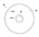
- the entire shape of the mold 10 is formed in a disc-like disk having a center hole 16, and a single-sided annular region 18 excluding the inner peripheral portion 17a and the outer peripheral portion 17b is shown in FIG. As shown in FIG. 3, the entire shape of the mold 10 is formed in a disc-like disk having a center hole 16, and a single-sided annular region 18 excluding the inner peripheral portion 17a and the outer peripheral portion 17b is shown in FIG. As shown in FIG.
- Metal substrate There is no restriction
- the thickness of the metal substrate 12 is preferably 100 ⁇ m to 1000 ⁇ m, and more preferably 200 ⁇ m to 750 ⁇ m.
- the metal substrate 12 is prepared, for example, by preparing a master having a concavo-convex pattern on the surface, electroforming a metal material on the pattern forming surface of the master to form an electroformed product on the master, and peeling the electroformed product, A metal substrate that is a multiple disk can be obtained.
- the metal substrate 12 can also be obtained by etching processing using photolithography that is generally performed.
- the protective film 16 protects the concavo-convex pattern P formed on the surface of the mold 10 from damage or adhesion of dust (foreign matter) during the transportation of the mold 10 or during the cutting process for adjusting the shape of the mold.
- the protective film 16 of the present invention is a polymer film composed of a urethane resin.
- NCO group isocyanate group in the organic isocyanate and the active hydrogen (H) in the active hydrogen-containing compound
- the paint is mainly composed of a urethane resin material and a diluting solvent as described later.
- the dilution solvent is not particularly limited, but it is preferable to use at least one solvent among isopropyl alcohol, ethyl acetate, methanol, ethanol and methyl ethyl ketone.
- the concentration of the resin component in the paint is preferably 17 to 21%.
- organic isocyanates can be used for the production of the liquid A.
- typical organic isocyanates include aromatic ones such as 2,4-tolylene diisocyanate alone or a mixture with 2,6-tolylene diisocyanate (hereinafter TDI), 4,4′-diphenylmethane diisocyanate (hereinafter “TDI”).
- MDI-PH or a mixture of 2,4′-diphenylmethane diisocyanate (hereinafter referred to as o-MDI), polymethylene polyphenyl polyisocyanate (hereinafter referred to as MDI-Cr), MDI-PH alone or a mixture of o-MDI
- MDI-LK liquid diphenylmethane diisocyanate
- organic isocyanates can be used alone or as a mixture, and those subjected to isocyanurate modification, carbodiimide modification, biuret modification, and allophanate modification can be used alone or in combination.
- organic isocyanates it is preferable to use an aromatic one considering the reactivity and mechanical properties of the cured product.
- MDI-PH alone or a mixture with o-MDI, MDI-Cr, MDI- One or a mixture of two or more selected from a simple substance of PH or MDI-LK is particularly preferable.
- E300 3,5-dimethylthio-2,4-toluenediamine and 3,5-dimethylthio-2,6-toluenediamine
- DETDA 6-toluenediamine
- the amount of DETDA to be used should be 50 mol% or less of the total amino groups in the total aromatic diamine in the B liquid, and if it exceeds 50 mol%, the reaction rate is pulled by DETDA and becomes extremely fast, so it must be avoided.
- the polyether and / or polyetheramine constituting the liquid B is mixed in an amount of 10 to 80 mol% of the total active hydrogen equivalent in the liquid B, so that the gelation time, the development of rubber elasticity, and the mechanical properties can be balanced. In addition, it enables the production of urethane elastomers with easy control of reactivity.
- an active hydrogen-containing compound having a hydroxyl value (amine value when the terminal is an amino group) of 120 or less include (1) water, (2) polyhydric alcohols such as ethylene glycol, propylene glycol, glycerin, trimethylolpropane and pentaerythritol, and ethylenediamine, triethylamine, diethylenetriamine, and triethanolamine.
- Polyether polyol obtained by addition polymerization of one or more of alkylene oxides such as ethylene oxide, propylene oxide and butylene oxide, and (3) tetrahydrofuran alone or together with alkylene oxide
- Polytetramethylene ether glycol obtained by addition polymerization
- Polyester polyol by dehydration condensation of carboxylic acid and low molecular weight glycol (5) Caprolactone Engaged polycaprolactone polyols were, (6) castor oil, and (7) a polycarbonate polyol.
- polymer polyols obtained by graft polymerization of ethylenically unsaturated compounds such as acrylonitrile, styrene and methyl methacrylate to these known polyols, 1,2- or 1,4-added polybutadiene polyols, and hydrogenated products thereof can also be used.
- Polyether amines in which the terminal hydroxyl group (OH group) of the polyether polyol is an amino group can also be used.
- the preferred hydroxyl value of these active hydrogen-containing compounds is in the range of 18 to 120.
- the low molecular polyol used as a cross-linking agent excluding E300 is preferably a hydroxyl group having a molecular weight of 400 or less with a small molecular weight per hydroxyl group.
- Typical examples are ethylene glycol (EG), diethylene glycol (DEG), propylene glycol (PG), dipropylene glycol (DPG), tripropylene glycol (TPG), tetrapropylene glycol, glycerin, trimethylolpropane, pentaerythritol. 1,4-butylene glycol, 1,3-butylene glycol, 1,2-butylene glycol and the like.
- the said low molecular polyol is used individually or in mixture of 2 or more types.
- the amount used is preferably such that the equivalent of the total cross-linking agent including the low molecular weight polyol and E300 is 90% or less of the equivalent of the entire liquid B.
- the molar ratio (NCO / H ratio) in the case of producing the liquid A is an important item and is a numerical value indicating the number of NCO groups with respect to one active hydrogen group (hydroxyl group and amino group).
- an organic isocyanate having two functional groups such as TDI, MDI-PH, etc.
- the molar ratio is 2
- the total amount of the prepolymer is obtained with an isocyanate group added to all terminals of the active hydrogen-containing compound. It becomes.
- the molar ratio is less than 2 it usually takes a sandwich structure and does not form a so-called “partial prepolymer” because there is no free organic isocyanate.
- the molar ratio during production of the prepolymer (liquid A) used in the present invention is preferably 4 to 30, and more preferably 6 to 20.
- the viscosity as the prepolymer (liquid A) decreases, but the amount of free organic isocyanate increases and the chain extension reaction is difficult to proceed. It tends to be low, and it is not preferable to make it larger than necessary.
- the isocyanate group content (hereinafter referred to as NCO%) of the liquid A is determined by the type and molar ratio (NCO / H ratio) of the organic isocyanate and the active hydrogen-containing compound at the time of production.
- NCO% of the prepolymer (liquid A) obtained when the molar ratio is in the range of 4 to 30 is about 2 to 30.
- the hydroxyl value (amine value when the terminal is an amino group) of the active hydrogen-containing compound used for the production of solution A is 18 In the range of ⁇ 120, particularly preferred is 18 ⁇ 60.
- a known urethane catalyst can be used, and among them, an organometallic material is preferable because it can reduce a foaming phenomenon caused by water.
- Typical examples include lead octylate, dibutyltin dilaurate, bismuth trineodecanoate, bismuth octylate, and iron octylate.
- Plasticizers such as dioctyl phthalate (DOP), adipate esters such as dioctyl adipate (DOA), and sebacates such as dioctyl sebacate (DOS).
- DOP dioctyl phthalate
- DOA dioctyl adipate
- DOS dioctyl sebacate
- System and antimony system can be used alone or in combination.
- the additives are tricresyl phosphate (TCP), chlorinated paraffin, tris- ⁇ -chloropropyl phosphate (TCPP), tris-chloroethyl phosphate (CLP), triphenyl phosphate (TPP).
- TPP tris- ⁇ -chloropropyl phosphate
- CLP tris-chloroethyl phosphate
- TPP triphenyl phosphate
- Tetrabromobisphenol A (TBA), dibromoneopentyl glycol (DBNPG), tribromoneopentyl alcohol (TBNPA), antimony triacid and the like are preferable, and the amount used is preferably about 5 to 50%.
- a heat stabilizer As the stabilizer, a heat stabilizer, an ultraviolet absorber, and a weather stabilizer are used alone or in combination.
- position-impaired phenol resins such as Irganox # 1010 and 1076 (Ciba-Geigy), Yoshinox BHT, BB and GSY-930 (Yoshitomi Pharmaceutical), and benzoins such as Tinuvin P, 327 and 328 (Ciba-Geigy) Triazoles, benzophenones such as Tomisorp 800 (Yoshitomi Pharmaceutical Co., Ltd.), and position hindered amines such as Sanol LS-770, 744, and 765 are used in an amount of about 0.05 to 3%.
- the type of the compatibilizer may be an anion or cation type, but an electrically neutral type shows good results.
- Addition may be either liquid A or liquid B, but is preferably added to liquid B in consideration of the storage stability of the material.
- an electrically neutral type Anti-Terra U (a salt of a long-chain polyaminoamide and a polar acid ester) manufactured by Big Chemie, W002 (Ionized neutral long-chain polyaminoamide and a polymer acid) manufactured by Yusho Co., Ltd. Ester salt), Florene G-820 (Kyoeisha Yushi), Disparon # 1830 (Enomoto Kasei), etc., and the amount used is about 0.2 to 5% in the resin.
- Anti-foaming agents can be used in both silicon and non-silicon types. Silicon-based L-45 (Nihon Unicar Co., Ltd.), non-silicon type Florene AC-1190 (Kyoeisha Yushi) etc. About 10 to 500 ppm in the liquid.
- an inorganic filler can be added to increase hardness, increase mechanical strength, increase acid resistance / alkali resistance, and the like.
- known materials can be used, for example, fine powders such as heavy calcium carbonate, talc, kaolin clay, mica, needle-like crystals of colloidal silica and calcium silicate, and the like. If the amount used is increased, the viscosity of the system increases, so the amount used is 5 to 70%, preferably 10 to 50%.
- a dynamic mixer that stirs and mixes by rotating a rotor
- a static in-tube mixing (static mixer) type and a collision mixing type spray gun
- a collision mixing type spray gun examples include a mechanical cleaning system (GX-7; manufactured by Gasmer, USA) and an air cleaning system (Probler gun; manufactured by Glasscraft, USA).
- a commercially available paint can be used, for example, MT Orester (registered trademark) NL2249E manufactured by Mitsui Chemicals, Inc. can be used.
- a method for forming the protective film as described above an injection method for injecting a resin into a metal mold or a resin bag, a spray method for atomizing a material in the air, a spin coating method, or the like can be used. .
- the rotation speed is 300 to 700 rpm and the rotation time is 40 to 120 s.
- the protective film is naturally dried or heat dried. The drying temperature and time can be adjusted according to the use such as long-term storage.
- the drying time when the drying time is short, the adhesion can be maintained for a long time.
- the heating temperature is preferably 35 to 65 ° C., and the heating time is preferably adjusted appropriately within a range of 3 to 25 minutes, with about 15 minutes as a guide.
- the formation method of the magnetic layer 14 is not particularly limited, and vacuum film formation such as sputtering, vapor deposition, ion plating, ALD (Atomic Layer Deposition), and CVD (Chemical Vapor Deposition). Means and known methods such as plating (including electroless plating) can be used.
- the thickness of the magnetic layer 14 is preferably 10 to 500 nm, and more preferably 10 to 50 nm.
- a coating liquid obtained by mixing a liquid (A) and a resin (liquid B) obtained by mixing an aromatic diamine, a polyol and / or a polyetheramine, and a curing catalyst, and having an uneven pattern Applying paint on the surface and drying the applied paint to form a protective film on the surface. It can be formed.
- a specific urethane-based resin film has excellent releasability from the concavo-convex pattern forming surface.
- the detailed mechanism is not clear, it is possible to form a film with almost no monomer due to its high cohesiveness, and because the film has high elasticity and does not break due to the anchor effect or edge effect. Presumed. Therefore, in the formation of a protective film for protecting the mold surface, it is possible to form a protective film that does not cause residual defects when it is peeled off even for a mold having an uneven pattern formed with a fine line width of, for example, 30 nm. Become.
- the protective film is peeled off because the mold having a fine concavo-convex pattern on the surface and the protective film formed by the protective film forming method described above are provided. No residue defects occur. As a result, it is possible to transfer the pattern with high accuracy and high yield in the mold with a protective film for protecting the surface.
- the protective film is formed by the method for forming a protective film described above.
- the method for manufacturing a mold with a protective film for protecting the surface it is possible to manufacture a mold capable of pattern transfer with high accuracy and high yield.
- MDI-PH 4,4′-diphenylmethane diisocyanate
- NCO% 33.6
- Solution A was prepared by the following method.
- Table 1 summarizes the raw materials used and the adjustment results for each of the liquids A (A-1 to A-6).
- Liquid B was prepared by the following method.
- B-3 Using the same mixer as B-1, Diol-2000EO (650 g) as a polyol and E300 (235 g) and DETDA (100 g) as an aromatic diamine were charged. The DETDA molar ratio at this time is 34%. Subsequently, the mixture was mixed at 80 ° C. for 1 hour under a nitrogen stream at 800 rpm for 1 minute. Next, P-25 (15 g) was added as a catalyst, and the mixture was mixed under a nitrogen stream at 80 ° C. for 30 minutes and 800 rpm for 1 minute. Next, the mixer was depressurized to 30 mmHg, and degassed for 30 minutes while stirring at 200 rpm for 1 minute. At this time, the equivalent of the wholly aromatic diamine was 84%, the viscosity was 600 cps / 25 ° C., and the specific gravity was 1.0.
- B-4 Using the same mixer as B-1, MN-1500 (301 g) as a polyol and E300 (453 g) and DETDA (30 g) as an aromatic diamine were charged. The DETDA molar ratio at this time is 7%. Subsequently, the mixture was heated to 80 ° C. and stirred and mixed for 30 minutes, and then whiten SSB [red] (200 g) was added as an inorganic filler, and the mixture was mixed under a nitrogen stream at 80 ° C. for 1 hour and 1000 rpm for 1 minute. .
- Mixing was performed under the condition of 1000 rpm for 1 minute.
- the mixer was depressurized to 30 mmHg, and degassed for 30 minutes while stirring at 200 rpm for 1 minute.
- the equivalent of the wholly aromatic diamine was 88%, the viscosity was 12,000 cps / 25 ° C., and the specific gravity was 1.2.
- B-5 Using the same mixer as B-1, Diol-1000 (165 g) and MN-1500 (165 g) as polyols and E300 (305 g) as aromatic diamines were charged, heated to 80 ° C., and stirred and mixed for 30 minutes. Thereafter, wollastonite G-40 (350 g) was added as an inorganic filler and mixed under a nitrogen stream at 80 ° C. for 3 hours and 1000 rpm for 1 minute. Next, Irganox # 1010 (2 g) and Tinuvin # 327 (2 g) as stabilizers, Floren AC-1190 (1 g) as antifoaming agent, P-25 (10 g) as catalyst, and 1 at 80 ° C. under a nitrogen stream.
- Diol-1000 (165 g) and MN-1500 (165 g) as polyols and E300 (305 g) as aromatic diamines were charged, heated to 80 ° C., and stirred and mixed for 30 minutes. Thereafter, wollast
- B-6 Using the same mixer as B-1, Diol-1000 (179 g) and MN-1500 (179 g) as polyols and DETDA (277 g) as aromatic diamines were charged, heated to 80 ° C., and stirred and mixed for 30 minutes. Thereafter, wollastonite G-40 (350 g) was added as an inorganic filler, and the mixture was mixed under a nitrogen stream at 80 ° C. for 3 hours and 1000 rpm for 1 minute. Next, Irganox # 1010 (2 g) and Tinuvin # 327 (2 g) as stabilizers, Floren AC-1190 (1 g) as antifoaming agent, P-25 (10 g) as catalyst, and 1 at 80 ° C.
- Table 3 is a table summarizing the adjustment results of the resin components (C-1 to C-7) prepared by appropriately mixing liquid A and liquid B used in Examples and Comparative Examples.
- the resin component C-1 was diluted with a diluent solvent consisting of isopropyl alcohol (IPA) (76.3%) and ethyl acetate (4.7%) to obtain a paint having a resin component concentration of 19%.
- IPA isopropyl alcohol
- ethyl acetate 4.7%)
- a Ni plate having a fine concave-convex pattern (a pseudo servo pattern in which a line & space pattern and a dot pattern are mixed) having a minimum line width of 19 nm on the surface is prepared, and the above-mentioned Ni plate is formed on the pattern forming surface.
- the paint was applied, and spin coating was performed under the conditions that the rotation speed was 300 rpm and the rotation time was 60 s. Thereafter, under the conditions that the drying temperature was 50 ° C. and the drying time was 15 minutes, the applied paint was heated and dried to form a protective film on the pattern forming surface of the Ni plate.
- Example 2 A protective film was formed in the same manner as in Example 1 except that the rotation speed of the spin coat was 500 rpm.
- Example 3 A protective film was formed in the same manner as in Example 1 except that the rotation speed of spin coating was 700 rpm.
- Example 4 A protective film was formed in the same manner as in Example 2 except that the drying temperature was 35 ° C.
- Example 5 A protective film was formed in the same manner as in Example 2 except that the drying temperature was 65 ° C.
- Example 6 A protective film was formed in the same manner as in Example 2 except that the drying time was 3 minutes.
- Example 7 A protective film was formed in the same manner as in Example 2 except that the drying time was 25 minutes.
- Example 9 Resin component C-1 was diluted with a diluent solvent consisting of IPA (73.8%) and ethyl acetate (5.2%) to obtain a paint having a resin component concentration of 21%. Thus, a protective film was formed.
- a diluent solvent consisting of IPA (73.8%) and ethyl acetate (5.2%)
- Example 10 A protective film was formed in the same manner as in Example 2 except that the diluent solvent was composed of IPA (38.6%), ethyl acetate (4.7%), and methyl ethyl ketone (37.7%).
- the diluent solvent was composed of IPA (38.6%), ethyl acetate (4.7%), and methyl ethyl ketone (37.7%).
- Example 11 A protective film was formed in the same manner as in Example 2 except that the diluent solvent was composed of IPA (38.6%), ethyl acetate (4.7%), and methanol (37.7%).
- Example 12 A protective film was formed in the same manner as in Example 2 except that the diluent solvent was composed of IPA (38.6%), ethyl acetate (4.7%), and ethanol (37.7%).
- Example 13 A protective film was formed in the same manner as in Example 2 except that the dilution solvent was composed of IPA (38.6%) and ethyl acetate (42.4%).
- Resin component C-1 was diluted with a diluent solvent consisting of IPA (78.8%) and ethyl acetate (4.2%) to obtain a paint having a resin component concentration of 17%. Thus, a protective film was formed.
- Resin component C-1 was diluted with a diluent solvent consisting of IPA (73.8%) and ethyl acetate (5.2%) to obtain a paint having a resin component concentration of 21%. Thus, a protective film was formed.
- Example 16 A protective film was formed in the same manner as in Example 2 except that the base material was a quartz plate.
- Example 17 A protective film was formed in the same manner as in Example 2 except that the base material was a Si wafer.
- Example 18 A protective film was formed in the same manner as in Example 2 except that the minimum line width of the concave portion of the concave / convex pattern was 30 nm.
- Example 19 A protective film was formed in the same manner as in Example 2 except that the minimum line width of the concave portion of the concave / convex pattern was 45 nm.
- Example 20 A protective film was formed in the same manner as in Example 2 except that the minimum line width of the concave portion of the concave-convex pattern was 60 nm.
- a protective film was formed in the same manner as in FIG.
- a protective film was formed in the same manner as in FIG.
- a protective film was formed in the same manner as in FIG.
- Example 24 A protective film was formed in the same manner as in Example 2 except that the spin coating rotation time was 40 s.
- Example 25 A protective film was formed in the same manner as in Example 2 except that the spin coating rotation time was 120 s.
- Example 26 A protective film was formed in the same manner as in Example 2 except that the spin coating rotation time was 600 s.
- Comparative Example 2 A protective film was formed in the same manner as in Comparative Example 1 except that the minimum line width of the concave portion of the concave / convex pattern was 30 nm.
- Comparative Example 3 A protective film was formed in the same manner as in Comparative Example 1 except that the minimum line width of the concave portion of the concave / convex pattern was 45 nm.
- Comparative Example 4 A protective film was formed in the same manner as in Comparative Example 1 except that the minimum line width of the concave portion of the concave-convex pattern was 60 nm.
- Example 7 A protective film was formed in the same manner as in Example 2 except that the rotation speed of the spin coat was 100 rpm.
- Example 8 A protective film was formed in the same manner as in Example 2 except that the rotation speed of the spin coat was 1000 rpm.
- Example 9 A protective film was formed in the same manner as in Example 2 except that the drying temperature was 30 ° C.
- Example 10 A protective film was formed in the same manner as in Example 2 except that the drying temperature was 70 ° C.
- Comparative Example 6 it is considered that the resin component concentration is high and the interaction between the substrate and the resin component is increased, resulting in a residue defect.
- Comparative Example 7 it is considered that a residual defect occurred because the coating speed did not sufficiently spread on the substrate because the rotational speed was low and the protective film could not be cured sufficiently.
- Comparative Example 9 it is considered that a residue defect occurred because the drying temperature was low and the protective film was not sufficiently dried.
- Comparative Example 10 it is considered that the drying temperature was high and the protective film was dried too much, resulting in an increase in adhesion and a residue defect.
- Comparative Example 11 it is considered that the strength of the protective film was reduced due to insufficient curing of the resin component, resulting in residual defects.
- Comparative Example 12 it is considered that the resin component coverage was low and the strength of the protective film was reduced, resulting in residual defects.
- Comparative Example 13 it is considered that a residue defect occurred because the adhesive strength of the resin component itself was weak.
- Comparative Example 14 it is considered that residual defects occurred due to insufficient curing due to insufficient rotation time of the spin coating and non-uniformity of the protective film thickness. In addition, when the spin coating rotation time is insufficient, there may be a problem that a protective film is not partially formed due to uneven coating of the paint.
- the results of Examples 1 to 3 indicate that the rotation speed can be adjusted in the range of 300 to 700 rpm when the coating is applied by spin coating. From the results of Examples 2, 4 and 5, it can be seen that the drying temperature can be adjusted in the range of 35 to 65 ° C. From the results of Examples 2, 6 and 7, it can be seen that the drying time can be adjusted in the range of 3 to 25 ° C. From the results of Examples 2, 8 and 9, it can be seen that the resin component concentration can be adjusted in the range of 17 to 21%. From the results of Examples 2 and 10 to 15, it can be seen that the effect of the present invention does not depend on the type of the diluent solvent. From the results of Examples 2, 16 and 17, it can be seen that the effect of the present invention does not depend on the material of the substrate.
- the present invention is not limited to this, and an imprint mold or the like (for patterned media, for forming a semiconductor wiring pattern). It can also be applied to substrates for optical elements, biochips, etc.).
Landscapes
- Engineering & Computer Science (AREA)
- Mechanical Engineering (AREA)
- Polyurethanes Or Polyureas (AREA)
- Application Of Or Painting With Fluid Materials (AREA)
Abstract
微細な凹凸パターンPを表面に有するモールド(10)の上記表面を保護する保護膜(16)の形成方法において、有機イソシアネートおよび活性水素含有化合物が混合され、有機イソシアネート中のイソシアネート基(NCO基)と活性水素含有化合物中の活性水素(H)とがNCO/H=5.5/1~20/1モル比の範囲で反応して得られたイソシアネート基末端プレポリマー(A液)と、芳香族ジアミン、ポリオール及び/又はポリエーテルアミン、並びに硬化触媒が混合されて得られたレジン(B液)とが混合されて得られた塗料を用意し、凹凸パターン(P)がある上記表面に塗料を塗布し、塗布された塗料を乾燥させて、上記表面に保護膜(16)を形成する。
Description
本発明は、所定の凹凸パターンを表面に有するモールドの凹凸パターン形成面を保護する保護膜の形成方法、並びに、それを利用した保護膜付モールドおよび保護膜付モールドの製造方法に関するものである。
近年、2次元的または3次元的なパターン転写を効率的に行う磁気転写方法およびナノインプリント方法が開発されている。磁気転写は、磁気記録媒体の製造で行われる転写技術であり、微細な磁化パターンを表面に有する磁気転写用マスターディスクをスレーブ媒体(被転写媒体ともいう。)に密着させた状態で、転写用磁界を印加して、磁化パターンに対応した情報(例えばサーボ信号)をスレーブ媒体に転写する技術である。一方、ナノインプリントは、ディスクリートトラックメディア(DTM)やビットパターンドメディア(BPM)等の製造で行われる転写技術であり、微細な凹凸パターンを表面に有するナノインプリント用マスター担体を熱可塑性樹脂、光硬化樹脂等に押し当て、その凹凸パターンを樹脂に転写する技術である。このような技術によれば、上記のようなモールド(上記マスターディスクや上記マスター担体を含む)をスレーブ媒体に押し付けて、2次元的または3次元的なパターンを一括的に転写することができ、ナノレベルの微細パターンを容易にかつ低コストに形成することが可能である。
しかし、上記のようなモールドは、磁気記録媒体の製造工程とは別の工程で作製されるため、輸送中モールドのパターン形成面(凹凸パターンが形成された面)に異物が付着してしまうという問題が生じうる。例えば、このような状態のままモールドとレジストとを密着させてインプリントを行った場合、上記異物の付着部分を中心として周辺に及ぶ範囲まで、モールドとレジストとの密着が確保できず、転写の品質が低下する。そして、これは磁気記録媒体自体の信頼性の低下につながる。特に、記録した信号がサーボ信号の場合には、トラッキング機能が十分に得られずに信頼性が低下するという問題がある。
そこで、このような異物による問題を解決するために、例えば特許文献1に示されるように、パターン転写工程へ移行する際の輸送工程において、モールドのパターン形成面に保護膜を設ける手法がとられている。
しかしながら、DTMやBPMの製造に用いられるモールドは、例えば30nmという微細な線幅で凹凸パターンが形成されているため、上記のような保護膜をモールドから剥離した際に、保護膜の材料の一部が残渣としてわずかに残ってしまうという残渣欠陥の問題が生じうる。これは、微細化に伴い、パターン形成面および保護膜の間のアンカー効果(接着剤が表面の凹凸や空隙に侵入したあと硬化することで、接着性を増す効果)が増大するためと考えられる。
本発明は上記問題に鑑みてなされたものであり、モールドの表面を保護する保護膜の形成において、剥離した時に残渣欠陥が生じない保護膜の形成を可能とする保護膜の形成方法を提供することを目的とするものである。
さらに本発明は、表面を保護する保護膜付のモールドにおいて、剥離した時に残渣欠陥が生じない保護膜を備えたことにより、高精度で歩留まりよくパターン転写することを可能とする保護膜付モールドおよびその製造方法を提供することを目的とするものである。
さらに本発明は、表面を保護する保護膜付のモールドの製造方法において、剥離した時に残渣欠陥が生じない保護膜を形成することにより、高精度で歩留まりよくパターン転写することを可能とするモールドの製造が可能な保護膜付モールドの製造方法を提供することを目的とするものである。
上記課題を解決するために、本発明に係る保護膜の形成方法は、
微細な凹凸パターンを表面に有するモールドの上記表面を保護する保護膜の形成方法において、
有機イソシアネートおよび活性水素含有化合物が混合され、有機イソシアネート中のイソシアネート基(NCO基)と活性水素含有化合物中の活性水素(H)とがNCO/H=5.5/1~20/1モル比の範囲で反応して得られたイソシアネート基末端プレポリマー(A液)と、芳香族ジアミン、ポリオール及び/又はポリエーテルアミン、並びに硬化触媒が混合されて得られたレジン(B液)とが混合されて得られた塗料を用意し、
凹凸パターンがある上記表面に塗料を塗布し、
塗布された塗料を乾燥させて、上記表面に保護膜を形成することを特徴とするものである。
微細な凹凸パターンを表面に有するモールドの上記表面を保護する保護膜の形成方法において、
有機イソシアネートおよび活性水素含有化合物が混合され、有機イソシアネート中のイソシアネート基(NCO基)と活性水素含有化合物中の活性水素(H)とがNCO/H=5.5/1~20/1モル比の範囲で反応して得られたイソシアネート基末端プレポリマー(A液)と、芳香族ジアミン、ポリオール及び/又はポリエーテルアミン、並びに硬化触媒が混合されて得られたレジン(B液)とが混合されて得られた塗料を用意し、
凹凸パターンがある上記表面に塗料を塗布し、
塗布された塗料を乾燥させて、上記表面に保護膜を形成することを特徴とするものである。
そして、本発明に係る保護膜の形成方法において、活性水素含有化合物の水酸基価は120以下であることが好ましい。
そして、塗料中における樹脂成分の濃度は17~21%であることが好ましい。
そして、イソプロピルアルコール、酢酸エチル、メタノール、エタノールおよびメチルエチルケトンのうち少なくとも1つの溶媒を用いて塗料を希釈し、希釈した塗料を上記表面に塗布することが好ましい。
そして、回転数が300~700rpmであり、回転時間が40~120sである条件の下、スピンコート法により塗料を塗布することが好ましい。
そして、加熱温度が35~65℃である条件の下、塗布された塗料を加熱して乾燥させることが好ましい。
そして、凹凸パターンの凹部の幅は20nm以下であることが好ましい。
さらに、本発明に係る保護膜付モールドは、微細な凹凸パターンを表面に有するモールドと、
上記に記載の保護膜の形成方法により形成された保護膜とを備えたことを特徴とするものである。
上記に記載の保護膜の形成方法により形成された保護膜とを備えたことを特徴とするものである。
さらに、本発明に係る保護膜付モールドの製造方法は、微細な凹凸パターンを表面に有し、この表面を保護する保護膜を備えた保護膜付モールドの製造方法において、
微細な凹凸パターンを表面に有するモールドを製造し、
上記に記載の保護膜の形成方法により保護膜を形成することを特徴とするものである。
微細な凹凸パターンを表面に有するモールドを製造し、
上記に記載の保護膜の形成方法により保護膜を形成することを特徴とするものである。
本発明に係る保護膜の形成方法によれば、微細な凹凸パターンを表面に有するモールドの上記表面を保護する保護膜の形成方法において、有機イソシアネートおよび活性水素含有化合物が混合され、有機イソシアネート中のイソシアネート基(NCO基)と活性水素含有化合物中の活性水素(H)とがNCO/H=5.5/1~20/1モル比の範囲で反応して得られたイソシアネート基末端プレポリマー(A液)と、芳香族ジアミン、ポリオール及び/又はポリエーテルアミン、並びに硬化触媒が混合されて得られたレジン(B液)とが混合されて得られた塗料を用意し、凹凸パターンがある上記表面に塗料を塗布し、塗布された塗料を乾燥させて、上記表面に保護膜を形成するから、ウレタン系樹脂から構成される剥離性の高い保護膜を形成することができる。したがって、モールドの表面を保護する保護膜の形成において、剥離した時に残渣欠陥が生じない保護膜の形成が可能となる。
また、本発明に係る保護膜付のモールドによれば、微細な凹凸パターンを表面に有するモールドと、上記に記載の保護膜の形成方法により形成された保護膜とを備えたから、保護膜を剥離した時に残渣欠陥が生じない。これより、表面を保護する保護膜付モールドにおいて、高精度で歩留まりよくパターン転写することが可能となる。
また、本発明に係る保護膜付のモールドの製造方法によれば、表面を保護する保護膜を備えた保護膜付モールドの製造において、上記に記載の保護膜の形成方法により保護膜を形成するから、保護膜を剥離した時に残渣欠陥が生じない保護膜付モールドを製造できる。これより、表面を保護する保護膜付モールドの製造方法において、高精度で歩留まりよくパターン転写することができるモールドの製造が可能となる。
以下、本発明の実施形態について図面を用いて説明するが、本発明はこれに限られるものではない。なお、視認しやすくするため、図面中の各構成要素の縮尺等は実際のものとは適宜異ならせてある。
(保護膜付モールド)
例えば、本発明の保護膜の形成方法、並びに、それを利用した保護膜付モールドおよび保護膜付モールドの製造方法が、磁気転写用モールドに適用された場合について説明する。
例えば、本発明の保護膜の形成方法、並びに、それを利用した保護膜付モールドおよび保護膜付モールドの製造方法が、磁気転写用モールドに適用された場合について説明する。
本実施形態の保護膜付きモールド10は、図1に示すように、微細な凹凸パターンを表面に有する金属基板12と、上記凹凸パターンの形状に沿って形成された磁性層14と、上記凹凸パターンを覆うように磁性層14上に形成された保護膜16とから構成される。
例えば、このような保護膜付きモールド10は、表面に凹凸パターンを有する金属基板12を用意し、当該金属基板12上に保護膜の原料となる樹脂を含有する塗料を塗布し、塗布された塗料を加熱乾燥させることにより製造される。
モールド10は、図2に示すように表面に磁気転写情報に対応した微細な凹凸パターンPを有しており、この凹凸面に磁性層14が被覆形成されてなる。なお、図には示さないが、磁性層14の上に剥離層や潤滑層を設ける態様が好ましい。
微細な凹凸パターンPの凸部は、平面視で長方形であり、トラック方向(ディスクの円周方向であり、図2の矢印方向)の長さAと、トラック幅方向(ディスクの半径方向)の長さL、並びに突起の高さ(厚さ)Hの値は、記録密度や記録信号波形等により適宜設計される。例えば、長さAが80nmに、長さLが200nmに設定される。ハードディスク装置に用いられる磁気ディスクのサーボ信号の場合、この微細な凹凸パターンPは、トラック方向の長さAに比べてトラック幅方向の長さLの方が長く形成される。例えば、トラック幅方向の長さLが0.05~20μm、トラック方向の長さAが0.05~5μmであることが好ましい。この範囲でトラック幅方向の方が長いパターンを選ぶことが、サーボ信号の情報を担持するパターンとしては好ましい。凸部パターンの高さH(凹部パターンの深さ)は、20~800nmの範囲が好ましく、30~600nmの範囲がより好ましい。凹凸パターンの凹部の幅は20nm以下であることが好ましい。本発明は、凹部の幅がこの範囲にある場合にも、従来に比して特に効果を発揮する。
また、図3に示すように、モールド10の全体形状は、中心孔16を有する円盤状のディスクに形成されており、内周部17aおよび外周部17bを除く片面の円環状領域18に図2のような凹凸パターンPが形成される。
(金属基板)
金属基板12の材料としては、特に制限はなく、目的に応じて適宜選択される。例えば、Ni、Si、Al、石英、ガラス、セラミックスおよび各種の合金等が挙げられる。金属基板12の厚みとしては、100μm~1000μmが好ましく、200μm~750μmがより好ましい。
金属基板12の材料としては、特に制限はなく、目的に応じて適宜選択される。例えば、Ni、Si、Al、石英、ガラス、セラミックスおよび各種の合金等が挙げられる。金属基板12の厚みとしては、100μm~1000μmが好ましく、200μm~750μmがより好ましい。
金属基板12は、例えば、表面に凹凸パターンを有する原盤を用意し、この原盤のパターン形成面に金属材料を電鋳して原盤上に電鋳物を形成し、この電鋳物を剥離することにより、複盤である金属基板を得ることができる。また、金属基板12は、一般的に行われているフォトリソグラフィを用いたエッチング加工によっても得ることができる。
(保護膜)
保護膜16は、モールド10の輸送中、或いはモールドの形状を整えるための切取り加工中、モールド10の表面に形成された凹凸パターンPを破損やゴミ(異物)の付着から保護するものである。本発明の保護膜16は、ウレタン系樹脂から構成されるポリマー膜である。
保護膜16は、モールド10の輸送中、或いはモールドの形状を整えるための切取り加工中、モールド10の表面に形成された凹凸パターンPを破損やゴミ(異物)の付着から保護するものである。本発明の保護膜16は、ウレタン系樹脂から構成されるポリマー膜である。
より詳細には、本発明の保護膜16は、有機イソシアネートおよび活性水素含有化合物が混合され、有機イソシアネート中のイソシアネート基(NCO基)と活性水素含有化合物中の活性水素(H)とがNCO/H=5.5/1~20/1モル比の範囲で反応して得られたイソシアネート基末端プレポリマー(A液)と、芳香族ジアミン、ポリオール及び/又はポリエーテルアミン、並びに硬化触媒が混合されて得られたレジン(B液)とが混合されて得られた塗料を用意し、凹凸パターンがある上記表面に塗料を塗布し、塗布された塗料を乾燥させて形成されたウレタン系樹脂膜である。
塗料は、主として後述するようなウレタン系樹脂の原料と、希釈溶媒から構成される。希釈溶媒は、特に限定されないが、イソプロピルアルコール、酢酸エチル、メタノール、エタノールおよびメチルエチルケトンのうち少なくとも1つの溶媒を用いることが好ましい。塗料中における樹脂成分の濃度は17~21%であることが好ましい。
(ウレタン系樹脂の原料)
A液の製造に使用する有機イソシアネートは種々のものが使用可能である。代表的な有機イソシアネートの例として、芳香族系のものでは、2,4-トリレンジイソシアネート単体又は2,6-トリレンジイソシアネートとの混合物(以下TDI)や、4,4’-ジフェニルメタンジイソシアネート(以下MDI-PH)の単体又は2,4’-ジフェニルメタンジイソシアネート(以下o-MDI)との混合物、ポリメチレンポリフェニルポリイソシアネート(以下MDI-Cr)、MDI-PHの単体又はo-MDIの混合物の一部をカルボジイミド変性した液状ジフェニルメタンジイソシアネート(以下MDI-LK)等が挙げられる。また、脂肪族又は脂環族系のものでは、ヘキサメチレンジイソシアネート(HDI)、イソホロンジイソシアネート(IPDI)、水添MDI-PH(H12MDI)、トリメチルキシレンジイソシアネート(TMXDI)及び/又はその水添品、キシレンジイソシアネート(XDI)及び/又はその水添品(H6 XDI)、トリメチルヘキサメチレンジイソシアネート(TMHDI)、シクロヘキシレンジイソシアネート(CHDI)、ノルボルナンジイソシアネート(NBDI)等が挙げられる。
A液の製造に使用する有機イソシアネートは種々のものが使用可能である。代表的な有機イソシアネートの例として、芳香族系のものでは、2,4-トリレンジイソシアネート単体又は2,6-トリレンジイソシアネートとの混合物(以下TDI)や、4,4’-ジフェニルメタンジイソシアネート(以下MDI-PH)の単体又は2,4’-ジフェニルメタンジイソシアネート(以下o-MDI)との混合物、ポリメチレンポリフェニルポリイソシアネート(以下MDI-Cr)、MDI-PHの単体又はo-MDIの混合物の一部をカルボジイミド変性した液状ジフェニルメタンジイソシアネート(以下MDI-LK)等が挙げられる。また、脂肪族又は脂環族系のものでは、ヘキサメチレンジイソシアネート(HDI)、イソホロンジイソシアネート(IPDI)、水添MDI-PH(H12MDI)、トリメチルキシレンジイソシアネート(TMXDI)及び/又はその水添品、キシレンジイソシアネート(XDI)及び/又はその水添品(H6 XDI)、トリメチルヘキサメチレンジイソシアネート(TMHDI)、シクロヘキシレンジイソシアネート(CHDI)、ノルボルナンジイソシアネート(NBDI)等が挙げられる。
これらの有機イソシアネートは単独又は混合物として使用するほか、イソシアヌレート変性、カルボジイミド変性、ビウレット変性、アロファネート変性を行ったものを単独又は混合して使用することができる。これらの有機イソシアネートの中で、反応性及び硬化物の機械物性を考慮すると芳香族系のものを使用することが好ましく、MDI-PHの単体又はo-MDIとの混合物、MDI-Cr、MDI-PHの単体又はMDI-LKから選ばれる1種又は2種以上の混合物が特に好ましい。伸び及び機械物性を優先する場合は官能基数が2のMDI-PH及び/又はo-MDIの含有量を多くし、高硬度を優先する場合は官能基数の多いMDI-Crを使用することが好ましい。
B液中の芳香族ジアミンには、3,5-ジメチルチオ-2,4-トルエンジアミンと3,5-ジメチルチオ-2,6-トルエンジアミンの混合物(Ethacure#300;以下E300)を必須成分として使用する。E300はイソシアネート基との反応速度がマイルドなため、単独で使用してもポットライフ(作業可能時間)を確保することが可能である。しかし、単独ではゲル化時間、ゴム弾性の発現性、機械物性のバランスやコントロールが難しいので、E300の一部を3,5-ジエチル-2,4-トルエンジアミンと3,5-ジエチル-2,6-トルエンジアミンの混合物(以下DETDA)に置き換えても良い。DETDAの使用量はB液中の全芳香族ジアミン中の全アミノ基の50モル%以下とし、50モル%を超えると反応速度がDETDAに引っ張られ極端に速く成るため避けなければならない。また、B液を構成するポリエーテル及び/又はポリエーテルアミンはB液中の全活性水素当量の10~80モル%混合することにより、ゲル化時間とゴム弾性の発現及び機械物性にバランスのとれた、反応性のコントロールが容易なウレタンエラストマーの製造を可能にする。
本発明のA液及びB液の製造には、水酸基価(末端がアミノ基の場合はアミン価)が120以下の活性水素含有化合物を使用することが好ましい。代表的な活性水素含有化合物には、(1)水、(2)エチレングリコール、プロピレングリコール、グリセリン、トリメチロールプロパンおよびペンタエリスリトール等の多価アルコール、並びに、エチレンジアミン、トリエチルアミン、ジエチレントリアミンおよびトリエタノールアミン等のアミン系開始剤に、エチレンオキサイド、プロピレンオキサイドおよびブチレンオキサイド等のアルキレンオキサイドの1種又は2種以上を付加重合して得たポリエーテルポリオール(PPG)、(3)テトラヒドロフランを単独又はアルキレンオキサイドと共に付加重合して得たポリテトラメチレンエーテルグリコール(PTMEG)、(4)カルボン酸と低分子グリコールとの脱水縮合によるポリエステルポリオール、(5)カプロラクトンを重合させたポリカプロラクトンポリオール、(6)ヒマシ油、(7)ポリカーボネートポリオール等が挙げられる。
中でも特にPTMEGを使用することにより、機械物性を著しく向上させることができる。これらの公知ポリオールにアクリロニトリル、スチレン、メチルメタクリレート等のエチレン性不飽和化合物をグラフト重合させて得たポリマーポリオールや1,2-又は1,4-付加のポリブタジエンポリオール及びこれらの水素添加物も使用できる。上記ポリエーテルポリオールの末端水酸基(OH基)をアミノ基としたポリエーテルアミンも使用できる。これら活性水素含有化合物の好ましい水酸基価(末端がアミノ基の場合はアミン価)の範囲は18~120である。
一方、E300を除く架橋剤として使用する低分子ポリオールは、水酸基1個当たりの分子量を小さくした水酸基価400以下のものが好ましい。代表的な例としては、エチレングリコール(EG)、ジエチレングリコール(DEG)、プロピレングリコール(PG)、ジプロピレングリコール(DPG)、トリプロピレングリコール(TPG)、テトラプロピレングリコール、グリセリン、トリメチロールプロパン、ペンタエリスリトール、1,4-ブチレングリコール、1,3-ブチレングリコール、1,2-ブチレングリコール等が挙げられる。上記低分子ポリオールは、単独又は2種以上を混合して使用する。その使用量は該低分子ポリオールとE300を含む全架橋剤の当量がB液全体の当量の90%以下とすることが好ましい。
A液を製造する場合のモル比(NCO/H比)は重要な項目であり、活性水素基(水酸基及びアミノ基)1個に対するNCO基の数を示す数値である。理論的には、官能基数が2の有機イソシアネート、例えばTDI、MDI-PH等において、上記モル比が2である場合、活性水素含有化合物の末端全てにイソシアネート基が付加した状態で全量がプレポリマーとなる。モル比が2未満の場合は、通常サンドイッチ構造を取り、フリーの有機イソシアネートが無いため通称『部分プレポリマー』とは成らない。一方、モル比が2を超えるとフリーの有機イソシアネートが存在し、プレポリマーとフリーの有機イソシアネートが混在した部分プレポリマーとなる。また、官能基数が2を超える有機イソシアネート、例えばMDI-LKやMDI-Cr等の場合は、そのイソシアネートの官能基数以上のモル比で無いと部分プレポリマーは製造できない。通常これらの有機イソシアネートは、官能基数が3以下のため、部分プレポリマーを製造するには、モル比が4以上必要である。また、モル比が低いとA液の粘度が高くなる傾向があるため、粘度を低くするためにはモル比を高めに設定する必要がある。従って本発明で使用するプレポリマー(A液)製造時のモル比は、4~30が好ましく、より好ましいモル比は6~20である。反対にモル比が30を超えると、プレポリマー(A液)としての粘度は低下するが、フリーの有機イソシアネート量が多くなり鎖伸長反応が進み難くなるため、ゴム弾性の発現性及び機械物性が低くなる傾向があり、必要以上に大きくすることは好ましくない。
A液のイソシアネート基含有率(以下NCO%)は、製造時の有機イソシアネートと活性水素含有化合物の種類とモル比(NCO/H比)により決定される。しかし、モル比を4~30の範囲とした場合に得られるプレポリマー(A液)のNCO%は、概ね2~30程度になる。本発明に好ましいA液のNCO%である8~22%程度を満足するためには、A液の製造に使用する活性水素含有化合物の水酸基価(末端がアミノ基の場合はアミン価)は18~120の範囲で、特に好ましいのは18~60である。本発明で使用するA液及びB液の25℃における粘度を共に2,000センチポイズ以下、好ましくは1,000センチポイズ以下とすることで、保護膜に最適な材料とすることができる。
硬化触媒としては、公知のウレタン用触媒が使用可能であり、中でも有機金属系の材料が水に起因する発泡現象を低減でき好ましい。代表的な例としては、オクチル酸鉛、ジブチル錫ジラウレート、トリネオデカン酸ビスマス、オクチル酸ビスマス、オクチル酸鉄等である。使用量は、無機充填材が添加された場合は樹脂の硬化速度が低下するため添加量を多くする必要があるが、通常はB液中に0.1~5%程度である。
本発明に使用できる添加剤は、公知の可塑剤、難燃剤、安定剤、相溶化剤、充填材、着色剤等で、必要により加えることができる。可塑剤として、例えばジオクチルフタレート(DOP)等のフタル酸エステル系、ジオクチルアジペート(DOA)等のアジピン酸エステル系、ジオクチルセバケート(DOS)等のセバケート系を、難燃剤としては、リン系、ハロゲン系及びアンチモン系を単独及び混合して使用できる。より具体的には、添加剤は、リン酸トリクレジル(TCP)、塩素化パラフィン、トリス-β-クロロプロピルフォスフェート(TCPP)、トリス-クロロエチルフォスフェート(CLP)、トリフェニルフォスフェート(TPP)、テトラブロムビスフェノールA(TBA)、ジブロムネオペンチルグリコール(DBNPG)、トリブロムネオペンチルアルコール(TBNPA)、三酸価アンチモン等が好ましく、使用量は5~50%程度が好ましい。
安定剤としては、耐熱安定剤、紫外線吸収剤、耐候安定剤を単独又は組み合わせて使用する。例えば、イルガノックス#1010及び1076(チバ・ガイギー社)、ヨシノックスBHT、BB及びGSY-930(吉富製薬社)等の位置障害型フェノール樹脂類、チヌビンP、327及び328(チバガイギー社)等のベンゾトリアゾール類、トミソープ800(吉富製薬社)等のベンゾフェノン類、サノールLS-770、744、765等の位置障害型アミン類でその使用量は0.05~3%程度である。
湿潤・分散剤の添加によりA/B液の混合性が向上し、機械強度が高くなる傾向のため、湿潤・分散剤を必要に応じて加えることは有効である。相溶化剤のタイプは、アニオン又はカチオンタイプでも良いが電気的に中性タイプが良好な結果を示す。添加はA液およびB液のいずれでもかまわないが、材料の貯蔵安定性を考慮するとB液に添加するのが好ましい。電気的に中性のタイプとしては、ビック・ケミー社のアンチテラU(長鎖ポリアミノアマイドと極性酸エステルの塩)、裕商(株)のW002(電離中性長鎖型ポリアミノアマイドと高分子酸エステル塩)、フローレンG-820(共栄社油脂)、ディスパロン#1830(楠本化成)等であり使用量は樹脂中に0.2~5%程度である。
また、非発泡の硬化物を製造する場合は消泡剤を添加すると効果的である。消泡剤は、シリコン系及び非シリコン系のいずれも使用可能であり、シリコン系ではL-45(日本ユニカー社)等、非シリコン系ではフローレンAC-1190(共栄社油脂)等で使用量はB液中に10~500ppm程度である。
充填材としては、無機質の充填材を添加し、硬度アップ、機械強度アップ、耐酸/アルカリ性のアップ等を行うことができる。無機質の充填材は公知の材料が使用でき、例えば、重質炭酸カルシウム、タルク、カオリンクレー、雲母等の微粉末、コロイダルシリカ及び珪酸カルシウムの針状結晶等を使用できる。使用量を多くすると系の粘度が上がるため使用量は5~70%、好ましくは10~50%である。
2液の混合に用いるスプレーガンは、ローターの回転により撹拌・混合を行うダイナミックミキサー、静的管内混合(スタティックミキサー)方式及び衝突混合方式のスプレーガンを使用することができる。反応時間を短く設定した場合や、洗浄溶剤の回収し難い場合は衝突混合型の使用が好ましい。衝突混合方式のスプレーガンの例としては、ロッドの出し入れによる機械式クリーニング方式(GX-7;米国ガスマー社製)や空気による洗浄方式(プロブラーガン;米国グラスクラフト社製)等である。
上記のようなウレタン系樹脂を含有する塗料としては市販されている塗料を用いることもでき、例えば、三井化学株式会社製 MTオレスター(登録商標)NL2249Eを用いることができる。
(成膜方法)
上記のような保護膜の成膜方法としては、金属製モールド又は樹脂製の袋内に樹脂を注入する注入法、空気中に材料を霧化するスプレー法およびスピンコート法等を用いることができる。スピンコート法により成膜する場合には、回転数が300~700rpmであり、回転時間が40~120sである条件の下実施することが好ましい。なお、本発明はスピンコートの回転時間が長くする場合には特に制限を設ける必要はないが、上記数値範囲は保護膜の生産性を考慮したものである。成膜した後、保護膜を自然乾燥や加熱乾燥させる。長期保存等の用途に応じて乾燥させる温度や時間を調整することができる。例えば、乾燥時間が短い場合には、長期的に密着力を維持させることができる。加熱温度は、35~65℃が好ましく、加熱時間は15分程度を目安に3~25分の範囲で適宜調整することが好ましい。
上記のような保護膜の成膜方法としては、金属製モールド又は樹脂製の袋内に樹脂を注入する注入法、空気中に材料を霧化するスプレー法およびスピンコート法等を用いることができる。スピンコート法により成膜する場合には、回転数が300~700rpmであり、回転時間が40~120sである条件の下実施することが好ましい。なお、本発明はスピンコートの回転時間が長くする場合には特に制限を設ける必要はないが、上記数値範囲は保護膜の生産性を考慮したものである。成膜した後、保護膜を自然乾燥や加熱乾燥させる。長期保存等の用途に応じて乾燥させる温度や時間を調整することができる。例えば、乾燥時間が短い場合には、長期的に密着力を維持させることができる。加熱温度は、35~65℃が好ましく、加熱時間は15分程度を目安に3~25分の範囲で適宜調整することが好ましい。
(磁性層)
磁性層14の形成方法は、特に限定されず、スパッタリング、蒸着、イオンプレーティング、ALD(原子層堆積法:Atomic Layer Deposition)およびCVD(化学気相成長法:Chemical Vapor Deposition)等の真空成膜手段、並びに、メッキ(無電解メッキを含む)等の公知の手法を用いることができる。磁性層14の磁性材料としては、Co、Co合金(CoNi、CoNiZr、CoNbTaZr等)、Fe、Fe合金(FeCo、FeCoNi、FeNiMo、FeAlSi、FeAl、FeTaN)、Ni、Ni合金(NiFe)を用いることができる。特に、FeCo、FeCoNiが好ましく用いることができる。磁性層14の厚さは、10~500nmであることが好ましく、10~50nmであることがより好ましい。
磁性層14の形成方法は、特に限定されず、スパッタリング、蒸着、イオンプレーティング、ALD(原子層堆積法:Atomic Layer Deposition)およびCVD(化学気相成長法:Chemical Vapor Deposition)等の真空成膜手段、並びに、メッキ(無電解メッキを含む)等の公知の手法を用いることができる。磁性層14の磁性材料としては、Co、Co合金(CoNi、CoNiZr、CoNbTaZr等)、Fe、Fe合金(FeCo、FeCoNi、FeNiMo、FeAlSi、FeAl、FeTaN)、Ni、Ni合金(NiFe)を用いることができる。特に、FeCo、FeCoNiが好ましく用いることができる。磁性層14の厚さは、10~500nmであることが好ましく、10~50nmであることがより好ましい。
本発明の作用を説明する。
本発明に係る保護膜の形成方法によれば、微細な凹凸パターンを表面に有するモールドの上記表面を保護する保護膜の形成方法において、有機イソシアネートおよび活性水素含有化合物が混合され、有機イソシアネート中のイソシアネート基(NCO基)と活性水素含有化合物中の活性水素(H)とがNCO/H=5.5/1~20/1モル比の範囲で反応して得られたイソシアネート基末端プレポリマー(A液)と、芳香族ジアミン、ポリオール及び/又はポリエーテルアミン、並びに硬化触媒が混合されて得られたレジン(B液)とが混合されて得られた塗料を用意し、凹凸パターンがある上記表面に塗料を塗布し、塗布された塗料を乾燥させて、上記表面に保護膜を形成するから、ウレタン系樹脂から構成される剥離性の高い保護膜を形成することができる。
本発明に係る保護膜の形成方法によれば、微細な凹凸パターンを表面に有するモールドの上記表面を保護する保護膜の形成方法において、有機イソシアネートおよび活性水素含有化合物が混合され、有機イソシアネート中のイソシアネート基(NCO基)と活性水素含有化合物中の活性水素(H)とがNCO/H=5.5/1~20/1モル比の範囲で反応して得られたイソシアネート基末端プレポリマー(A液)と、芳香族ジアミン、ポリオール及び/又はポリエーテルアミン、並びに硬化触媒が混合されて得られたレジン(B液)とが混合されて得られた塗料を用意し、凹凸パターンがある上記表面に塗料を塗布し、塗布された塗料を乾燥させて、上記表面に保護膜を形成するから、ウレタン系樹脂から構成される剥離性の高い保護膜を形成することができる。
本発明者は、鋭意検討を重ねた結果、特定のウレタン系樹脂膜が、凹凸パターン形成面に対して優れた剥離性を有することを見出した。これは、詳細なメカニズムは定かではないが、凝集性の高さによりモノマーを殆ど残さない膜形成が可能であるため、また、膜の弾性が高くアンカー効果やエッジ効果による破断が生じないためと推定される。したがって、モールドの表面を保護する保護膜の形成において、例えば30nmという微細な線幅で形成された凹凸パターンを有するモールドに対しても、剥離した時に残渣欠陥が生じない保護膜の形成が可能となる。
また、本発明に係る保護膜付のモールドによれば、微細な凹凸パターンを表面に有するモールドと、上記に記載の保護膜の形成方法により形成された保護膜とを備えたから、保護膜を剥離した時に残渣欠陥が生じない。これより、表面を保護する保護膜付モールドにおいて、高精度で歩留まりよくパターン転写することが可能となる。
また、本発明に係る保護膜付のモールドの製造方法によれば、表面を保護する保護膜を備えた保護膜付モールドの製造において、上記に記載の保護膜の形成方法により保護膜を形成するから、保護膜を剥離した時に残渣欠陥が生じない保護膜付モールドを製造できる。これより、表面を保護する保護膜付モールドの製造方法において、高精度で歩留まりよくパターン転写することができるモールドの製造が可能となる。
本発明に係る保護膜の形成方法の実施例を以下に示す。なお、例中(表を含む)の数字は特に断るもの以外、グラム又は重量部を表わす。
<使用原料の説明>
(A液成分:有機イソシアネート)
・MDI-PH:4,4’-ジフェニルメタンジイソシアネート(三井東圧化学社製;NCO%=33.6)
・MDI-LK:カルボジイミド変性液状MDI(三井東圧化学社製;NCO%=29)
・MDI-Cr:ポリメリックMDI(三井東圧化学社製;NCO%=31)
・TDI-80:トリレンジイソシアネート(2,4-/2,6-比=80/20;三井東圧化学社製;NCO%=48.2)
(A液成分:有機イソシアネート)
・MDI-PH:4,4’-ジフェニルメタンジイソシアネート(三井東圧化学社製;NCO%=33.6)
・MDI-LK:カルボジイミド変性液状MDI(三井東圧化学社製;NCO%=29)
・MDI-Cr:ポリメリックMDI(三井東圧化学社製;NCO%=31)
・TDI-80:トリレンジイソシアネート(2,4-/2,6-比=80/20;三井東圧化学社製;NCO%=48.2)
(A液成分:ポリオール)
・Diol-12000:2官能ポリプロピレングリコール(PPG)[水酸基価=9.3]
・Triol-7000EO:3官能末端EOキャップポリプレングリコール[水酸基価=22]=プロピレンオキサイドを付加重合し一定の分子量まで鎖伸長した後、エチレンオキサイドを付加し末端の1級OHの比率を高めたPPG=
・Diol-3000EO:2官能末端EOキャップポリプロピレングリコール[水酸基価=37.4]
・Diol-3000:2官能ポリプロピレングリコール[水酸基価=37.4]
・Diol-1000:2官能ポリプロピレングリコール[水酸基価=112]
・Diol-400:2官能ポリプロピレングリコール[水酸基価=280]
・Diol-12000:2官能ポリプロピレングリコール(PPG)[水酸基価=9.3]
・Triol-7000EO:3官能末端EOキャップポリプレングリコール[水酸基価=22]=プロピレンオキサイドを付加重合し一定の分子量まで鎖伸長した後、エチレンオキサイドを付加し末端の1級OHの比率を高めたPPG=
・Diol-3000EO:2官能末端EOキャップポリプロピレングリコール[水酸基価=37.4]
・Diol-3000:2官能ポリプロピレングリコール[水酸基価=37.4]
・Diol-1000:2官能ポリプロピレングリコール[水酸基価=112]
・Diol-400:2官能ポリプロピレングリコール[水酸基価=280]
(B液成分)
・PTMEG-1000:ポリテトラメチレングリコール(デュポン社製;テラタン1000E)[水酸基価=112]
・Diol-2000EO:2官能末端EOキャップポリプロピレングリコール[水酸基価=56.1]
・MN-1500:3官能ポリプロピレングリコール[水酸基価=113]
・1,4-BD:1,4-ブチレングリコール[水酸基価=1247]
・E300:3,5-ジメチルチオ-2,4-トルエンジアミンと3,5-ジメチルチオ-2,6-トルエンジアミンの80対20の混合物(エチルコーポレーション製)[水酸基価=523]
・DETDA:3,5-ジエチル-2,4-トルエンジアミンと3,5-ジエチル-2,6-トルエンジアミンの80対20の混合物(エチルコーポレーション製)[水酸基価=630]
・PTMEG-1000:ポリテトラメチレングリコール(デュポン社製;テラタン1000E)[水酸基価=112]
・Diol-2000EO:2官能末端EOキャップポリプロピレングリコール[水酸基価=56.1]
・MN-1500:3官能ポリプロピレングリコール[水酸基価=113]
・1,4-BD:1,4-ブチレングリコール[水酸基価=1247]
・E300:3,5-ジメチルチオ-2,4-トルエンジアミンと3,5-ジメチルチオ-2,6-トルエンジアミンの80対20の混合物(エチルコーポレーション製)[水酸基価=523]
・DETDA:3,5-ジエチル-2,4-トルエンジアミンと3,5-ジエチル-2,6-トルエンジアミンの80対20の混合物(エチルコーポレーション製)[水酸基価=630]
・G-40:珪酸カルシウムの針状結晶(NYCO
MINERALS,Inc.;ウォラストナイトG-40)
・ホワイトンSSB[赤]:重質炭酸カルシウムの微粉末(白石カルシウム)
・イルガノックス#1010:酸化防止剤;テトラキス-〔メチレン-3-(3’,5’-ジ-第三-ブチル-4’-ヒドロキシフェニル)プロピオネート〕メタン(チバ・ガイギー社製)
・チヌビン#327:紫外線吸収剤;2-(2’-ヒドロキシ-3’,5’-ジ-第三-ブチル-フェニル)-5-クロロ・ベンゾトリアゾール(チバ・ガイギー社製)
・フローレンAC-1190:非シリコン系消泡剤(共栄社油脂製)
・Coscat#83:トリネオデカン酸ビスマス(Bi=16.6%)(コーサンケミカル社製)
・P-25:オクチル酸鉛の25%溶液(播磨化成社製)
MINERALS,Inc.;ウォラストナイトG-40)
・ホワイトンSSB[赤]:重質炭酸カルシウムの微粉末(白石カルシウム)
・イルガノックス#1010:酸化防止剤;テトラキス-〔メチレン-3-(3’,5’-ジ-第三-ブチル-4’-ヒドロキシフェニル)プロピオネート〕メタン(チバ・ガイギー社製)
・チヌビン#327:紫外線吸収剤;2-(2’-ヒドロキシ-3’,5’-ジ-第三-ブチル-フェニル)-5-クロロ・ベンゾトリアゾール(チバ・ガイギー社製)
・フローレンAC-1190:非シリコン系消泡剤(共栄社油脂製)
・Coscat#83:トリネオデカン酸ビスマス(Bi=16.6%)(コーサンケミカル社製)
・P-25:オクチル酸鉛の25%溶液(播磨化成社製)
<A液の調製>
A液の調製は下記の方法で行った。
A液の調製は下記の方法で行った。
(A-1)
MDI-PH(236g)にMDI-LK(236g)を加えた後、Diol-3000EO(528g)を加え窒素気流下80℃で3時間撹拌しながら反応させNCO%=13.2、粘度(cps/25℃)=1,000、比重(23/23℃)=1.12の部分プレポリマーを得た。この時のモル比(NCO/OH比)は10である。このA液は、粘度が低くスプレー用に適した材料である。
MDI-PH(236g)にMDI-LK(236g)を加えた後、Diol-3000EO(528g)を加え窒素気流下80℃で3時間撹拌しながら反応させNCO%=13.2、粘度(cps/25℃)=1,000、比重(23/23℃)=1.12の部分プレポリマーを得た。この時のモル比(NCO/OH比)は10である。このA液は、粘度が低くスプレー用に適した材料である。
(A-2)
MDI-PH(379g)にMDI-LK(253g)を加えた後、Diol-3000(276g)、Diol-1000(92g)を加え窒素気流下80℃で3時間撹拌しながら反応させNCO%=18.4、粘度(cps/25℃)=1,200、比重(23/23℃)=1.15の部分プレポリマーを得た。この時のモル比(NCO/OH比)は13である。
MDI-PH(379g)にMDI-LK(253g)を加えた後、Diol-3000(276g)、Diol-1000(92g)を加え窒素気流下80℃で3時間撹拌しながら反応させNCO%=18.4、粘度(cps/25℃)=1,200、比重(23/23℃)=1.15の部分プレポリマーを得た。この時のモル比(NCO/OH比)は13である。
(A-3)
MDI-PH(314g)にDiol-3000(686g)を加え窒素気流下80℃で3時間撹拌しながら反応させNCO%=8.4、粘度(cps/25℃)=6,500、比重(23/23℃)=1.09の部分プレポリマーを得た。この時のモル比(NCO/OH比)は5.5である。
MDI-PH(314g)にDiol-3000(686g)を加え窒素気流下80℃で3時間撹拌しながら反応させNCO%=8.4、粘度(cps/25℃)=6,500、比重(23/23℃)=1.09の部分プレポリマーを得た。この時のモル比(NCO/OH比)は5.5である。
(A-4)
MDI-Cr(515g)にTriol-7000EO(485g)を加え窒素気流下80℃で4時間撹拌しながら反応させNCO%=15.1、粘度(cps/25℃)=1,600、比重(23/23℃)=1.14の部分プレポリマーを得た。この時のモル比(NCO/OH比)は20である。
MDI-Cr(515g)にTriol-7000EO(485g)を加え窒素気流下80℃で4時間撹拌しながら反応させNCO%=15.1、粘度(cps/25℃)=1,600、比重(23/23℃)=1.14の部分プレポリマーを得た。この時のモル比(NCO/OH比)は20である。
(A-5)
MDI-PH(286g)にMDI-LK(286g)を加えた後、Diol-12000(428g)を加え窒素気流下90℃で3時間撹拌しながら反応させNCO%=17.5、粘度(cps/25℃)=2,600、比重(23/23℃)=1.11の部分プレポリマーを得た。この時のモル比(NCO/OH比)は60である。
MDI-PH(286g)にMDI-LK(286g)を加えた後、Diol-12000(428g)を加え窒素気流下90℃で3時間撹拌しながら反応させNCO%=17.5、粘度(cps/25℃)=2,600、比重(23/23℃)=1.11の部分プレポリマーを得た。この時のモル比(NCO/OH比)は60である。
(A-6)
TDI-80(566g)にDiol-400(434g)を混合し窒素気流下80℃で3時間撹拌しながら反応させたところ、全体の粘度が急激に上昇しゲル化した。計算NCO%は18.1、モル比(NCO/OH比)は3.0であり、モル比が4以下であり、使用したPPGの分子量も低いためゲル化したと考えられる。したがって、A液のA-6は本発明における原料としては不向きである。
TDI-80(566g)にDiol-400(434g)を混合し窒素気流下80℃で3時間撹拌しながら反応させたところ、全体の粘度が急激に上昇しゲル化した。計算NCO%は18.1、モル比(NCO/OH比)は3.0であり、モル比が4以下であり、使用したPPGの分子量も低いためゲル化したと考えられる。したがって、A液のA-6は本発明における原料としては不向きである。
下記表1は、A液(A-1~A-6)それぞれの使用原料及び調整結果をまとめた表である。

<B液の調製>
B液の調製は下記の方法で行った。
B液の調製は下記の方法で行った。
(B-1)
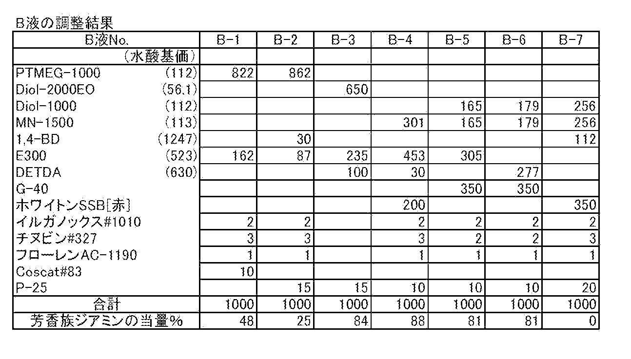
混合機(井上製作所製ディゾルバー)中にポリオールとしてPTMEG-1000(822g)と芳香族ジアミンE300(162g)を装入し80℃に昇温した後、安定剤としてイルガノックス#1010(2g)及びチヌビン#327(3g)、消泡剤としてフローレンAC-1190(1g)、触媒としてCoscat#83(10g)を加え窒素気流下80℃で1時間、1分間に800回転の条件で混合した。次に混合機を30mmHgの減圧とし、1分間に200回転の条件で撹拌しながら30分間脱泡した。この時の全芳香族ジアミンの当量は48%で粘度は900cps/25℃、比重は1.0であった。
混合機(井上製作所製ディゾルバー)中にポリオールとしてPTMEG-1000(822g)と芳香族ジアミンE300(162g)を装入し80℃に昇温した後、安定剤としてイルガノックス#1010(2g)及びチヌビン#327(3g)、消泡剤としてフローレンAC-1190(1g)、触媒としてCoscat#83(10g)を加え窒素気流下80℃で1時間、1分間に800回転の条件で混合した。次に混合機を30mmHgの減圧とし、1分間に200回転の条件で撹拌しながら30分間脱泡した。この時の全芳香族ジアミンの当量は48%で粘度は900cps/25℃、比重は1.0であった。
(B-2)
B-1と同一の混合機を用いポリオールとしてPTMEG-1000(862g)に1,4-BD(30g)と芳香族ジアミンとしてE300(87g)を装入した後、安定剤としてイルガノックス#1010(2g)及びチヌビン#327(3g)、消泡剤としてフローレンAC-1190(1g)、触媒としてP-25(15g)を加え窒素気流下80℃で1時間、1分間に800回転の条件で混合した。次に混合機を30mmHgの減圧とし、1分間に200回転の条件で撹拌しながら30分間脱泡した。この時の全芳香族ジアミンの当量は25%で粘度は850cps/25℃、比重は1.0であった。
B-1と同一の混合機を用いポリオールとしてPTMEG-1000(862g)に1,4-BD(30g)と芳香族ジアミンとしてE300(87g)を装入した後、安定剤としてイルガノックス#1010(2g)及びチヌビン#327(3g)、消泡剤としてフローレンAC-1190(1g)、触媒としてP-25(15g)を加え窒素気流下80℃で1時間、1分間に800回転の条件で混合した。次に混合機を30mmHgの減圧とし、1分間に200回転の条件で撹拌しながら30分間脱泡した。この時の全芳香族ジアミンの当量は25%で粘度は850cps/25℃、比重は1.0であった。
(B-3)
B-1と同一の混合機を用いポリオールとしてDiol-2000EO(650g)に、芳香族ジアミンとしてE300(235g)とDETDA(100g)を装入した。この時のDETDAモル比は、34%である。続いて窒素気流下80℃で1時間、1分間に800回転の条件で混合した。次に、触媒としてP-25(15g)を加え窒素気流下80℃で30分間、1分間に800回転の条件で混合した。次に混合機を30mmHgの減圧とし、1分間に200回転の条件で撹拌しながら30分間脱泡した。この時の全芳香族ジアミンの当量は84%で粘度は600cps/25℃、比重は1.0であった。
B-1と同一の混合機を用いポリオールとしてDiol-2000EO(650g)に、芳香族ジアミンとしてE300(235g)とDETDA(100g)を装入した。この時のDETDAモル比は、34%である。続いて窒素気流下80℃で1時間、1分間に800回転の条件で混合した。次に、触媒としてP-25(15g)を加え窒素気流下80℃で30分間、1分間に800回転の条件で混合した。次に混合機を30mmHgの減圧とし、1分間に200回転の条件で撹拌しながら30分間脱泡した。この時の全芳香族ジアミンの当量は84%で粘度は600cps/25℃、比重は1.0であった。
(B-4)
B-1と同一の混合機を用いポリオールとしてMN-1500(301g)、芳香族ジアミンとしてE300(453g)とDETDA(30g)を装入した。この時のDETDAモル比は、7%である。続いて80℃に昇温し30分間撹拌・混合した後、無機フィラーとしてホワイトンSSB[赤](200g)を加え、窒素気流下80℃で1時間、1分間に1000回転の条件で混合した。次に、安定剤としてイルガノックス#1010(2g)及びチヌビン#327(3g)、消泡剤としてフローレンAC-1190(1g)、触媒としてP-25(10g)を加え窒素気流下80℃で1時間、1分間に1000回転の条件で混合した。次に混合機を30mmHgの減圧とし、1分間に200回転の条件で撹拌しながら30分間脱泡した。この時の全芳香族ジアミンの当量は88%で粘度は12,000cps/25℃、比重は1.2であった。
B-1と同一の混合機を用いポリオールとしてMN-1500(301g)、芳香族ジアミンとしてE300(453g)とDETDA(30g)を装入した。この時のDETDAモル比は、7%である。続いて80℃に昇温し30分間撹拌・混合した後、無機フィラーとしてホワイトンSSB[赤](200g)を加え、窒素気流下80℃で1時間、1分間に1000回転の条件で混合した。次に、安定剤としてイルガノックス#1010(2g)及びチヌビン#327(3g)、消泡剤としてフローレンAC-1190(1g)、触媒としてP-25(10g)を加え窒素気流下80℃で1時間、1分間に1000回転の条件で混合した。次に混合機を30mmHgの減圧とし、1分間に200回転の条件で撹拌しながら30分間脱泡した。この時の全芳香族ジアミンの当量は88%で粘度は12,000cps/25℃、比重は1.2であった。
(B-5)
B-1と同一の混合機を用いポリオールとしてDiol-1000(165g)とMN-1500(165g)、芳香族ジアミンとしてE300(305g)を装入し80℃に昇温し30分間撹拌・混合した後、無機フィラーとしてウォラストナイトG-40(350g)加え、窒素気流下80℃で3時間、1分間に1000回転の条件で混合した。次に、安定剤としてイルガノックス#1010(2g)及びチヌビン#327(2g)、消泡剤としてフローレンAC-1190(1g)、触媒としてP-25(10g)を加え窒素気流下80℃で1時間、1分間に1000回転の条件で混合した。次に混合機を30mmHgの減圧とし、1分間に200回転の条件で撹拌しながら30分間脱泡した。この時の全芳香族ジアミンの当量は81%で粘度は31,000cps/25℃、比重は1.3であった。
B-1と同一の混合機を用いポリオールとしてDiol-1000(165g)とMN-1500(165g)、芳香族ジアミンとしてE300(305g)を装入し80℃に昇温し30分間撹拌・混合した後、無機フィラーとしてウォラストナイトG-40(350g)加え、窒素気流下80℃で3時間、1分間に1000回転の条件で混合した。次に、安定剤としてイルガノックス#1010(2g)及びチヌビン#327(2g)、消泡剤としてフローレンAC-1190(1g)、触媒としてP-25(10g)を加え窒素気流下80℃で1時間、1分間に1000回転の条件で混合した。次に混合機を30mmHgの減圧とし、1分間に200回転の条件で撹拌しながら30分間脱泡した。この時の全芳香族ジアミンの当量は81%で粘度は31,000cps/25℃、比重は1.3であった。
(B-6)
B-1と同一の混合機を用いポリオールとしてDiol-1000(179g)とMN-1500(179g)、芳香族ジアミンとしてDETDA(277g)を装入し80℃に昇温し30分間撹拌・混合した後、無機フィラーとしてウォラストナイトG-40(350g)を加え、窒素気流下80℃で3時間、1分間に1000回転の条件で混合した。次に、安定剤としてイルガノックス#1010(2g)及びチヌビン#327(2g)、消泡剤としてフローレンAC-1190(1g)、触媒としてP-25(10g)を加え窒素気流下80℃で1時間、1分間に1000回転の条件で混合した。次に混合機を30mmHgの減圧とし、1分間に200回転の条件で撹拌しながら30分間脱泡した。この時の全芳香族ジアミンの当量は81%で粘度は21,000cps/25℃、比重は1.3であった。
B-1と同一の混合機を用いポリオールとしてDiol-1000(179g)とMN-1500(179g)、芳香族ジアミンとしてDETDA(277g)を装入し80℃に昇温し30分間撹拌・混合した後、無機フィラーとしてウォラストナイトG-40(350g)を加え、窒素気流下80℃で3時間、1分間に1000回転の条件で混合した。次に、安定剤としてイルガノックス#1010(2g)及びチヌビン#327(2g)、消泡剤としてフローレンAC-1190(1g)、触媒としてP-25(10g)を加え窒素気流下80℃で1時間、1分間に1000回転の条件で混合した。次に混合機を30mmHgの減圧とし、1分間に200回転の条件で撹拌しながら30分間脱泡した。この時の全芳香族ジアミンの当量は81%で粘度は21,000cps/25℃、比重は1.3であった。
(B-7)
B-1と同一の混合機を用いポリオールとしてDiol-1000(256g)とMN-1500(256g)、1,4-BD(112g)を加え、80℃に昇温し30分間撹拌・混合した後、無機フィラーとしてホワイトンSSB[赤](350g)を加え、窒素気流下80℃で1時間、1分間に1000回転の条件で混合した。次に、安定剤としてイルガノックス#1010(2g)及びチヌビン#327(3g)、消泡剤としてフローレンAC-1190(1g)、触媒としてP-25(20g)を加え窒素気流下80℃で1時間、1分間に1000回転の条件で混合した。次に混合機を30mmHgの減圧とし、1分間に200回転の条件で撹拌しながら30分間脱泡した。このものは芳香族ジアミンが加えられていないため粘度は17,000cps/25℃、比重は1.3であった。
B-1と同一の混合機を用いポリオールとしてDiol-1000(256g)とMN-1500(256g)、1,4-BD(112g)を加え、80℃に昇温し30分間撹拌・混合した後、無機フィラーとしてホワイトンSSB[赤](350g)を加え、窒素気流下80℃で1時間、1分間に1000回転の条件で混合した。次に、安定剤としてイルガノックス#1010(2g)及びチヌビン#327(3g)、消泡剤としてフローレンAC-1190(1g)、触媒としてP-25(20g)を加え窒素気流下80℃で1時間、1分間に1000回転の条件で混合した。次に混合機を30mmHgの減圧とし、1分間に200回転の条件で撹拌しながら30分間脱泡した。このものは芳香族ジアミンが加えられていないため粘度は17,000cps/25℃、比重は1.3であった。
下記表2は、B液(B-1~B-7)それぞれの使用原料及び調整結果をまとめた表である。
下記表3は、実施例および比較例で用いる、A液およびB液を適宜混合して作製した樹脂成分(C-1~C-7)の調整結果をまとめた表である。

この樹脂成分(C-1~C-7)の中から1つを適宜選択し、下記のような実施例および比較例の実験を行った。
(実施例1)
まず、A液としてA-1をB液としてB-1を選択し、容積比でA/B=1/1の割合で混合し樹脂成分C-1を得た。この樹脂成分C-1をイソプロピルアルコール(IPA)(76.3%)および酢酸エチル(4.7%)からなる希釈溶媒で希釈し、樹脂成分濃度が19%の塗料を得た。次に、凹部の最小線幅が19nmである微細な凹凸パターン(ライン&スペースパターンおよびドットパターンが混在する擬似サーボパターン)を表面に有するNi板を用意し、当該Ni板のパターン形成面に上記塗料を塗布し、回転数が300rpmであり、回転時間が60sである条件の下、スピンコートを実施した。その後、乾燥温度が50℃であり、乾燥時間が15分である条件の下、塗布された塗料を加熱乾燥させて当該Ni板のパターン形成面に保護膜を形成した。
まず、A液としてA-1をB液としてB-1を選択し、容積比でA/B=1/1の割合で混合し樹脂成分C-1を得た。この樹脂成分C-1をイソプロピルアルコール(IPA)(76.3%)および酢酸エチル(4.7%)からなる希釈溶媒で希釈し、樹脂成分濃度が19%の塗料を得た。次に、凹部の最小線幅が19nmである微細な凹凸パターン(ライン&スペースパターンおよびドットパターンが混在する擬似サーボパターン)を表面に有するNi板を用意し、当該Ni板のパターン形成面に上記塗料を塗布し、回転数が300rpmであり、回転時間が60sである条件の下、スピンコートを実施した。その後、乾燥温度が50℃であり、乾燥時間が15分である条件の下、塗布された塗料を加熱乾燥させて当該Ni板のパターン形成面に保護膜を形成した。
(実施例2)
スピンコートの回転数が500rpmである点以外は、実施例1と同様にして保護膜を形成した。
スピンコートの回転数が500rpmである点以外は、実施例1と同様にして保護膜を形成した。
(実施例3)
スピンコートの回転数が700rpmである点以外は、実施例1と同様にして保護膜を形成した。
スピンコートの回転数が700rpmである点以外は、実施例1と同様にして保護膜を形成した。
(実施例4)
乾燥温度が35℃である点以外は、実施例2と同様にして保護膜を形成した。
乾燥温度が35℃である点以外は、実施例2と同様にして保護膜を形成した。
(実施例5)
乾燥温度が65℃である点以外は、実施例2と同様にして保護膜を形成した。
乾燥温度が65℃である点以外は、実施例2と同様にして保護膜を形成した。
(実施例6)
乾燥時間が3分である点以外は、実施例2と同様にして保護膜を形成した。
乾燥時間が3分である点以外は、実施例2と同様にして保護膜を形成した。
(実施例7)
乾燥時間が25分である点以外は、実施例2と同様にして保護膜を形成した。
乾燥時間が25分である点以外は、実施例2と同様にして保護膜を形成した。
(実施例8)
樹脂成分C-1をIPA(78.8%)および酢酸エチル(4.2%)からなる希釈溶媒で希釈し、樹脂成分濃度が17%の塗料を得た点以外は、実施例2と同様にして保護膜を形成した。
樹脂成分C-1をIPA(78.8%)および酢酸エチル(4.2%)からなる希釈溶媒で希釈し、樹脂成分濃度が17%の塗料を得た点以外は、実施例2と同様にして保護膜を形成した。
(実施例9)
樹脂成分C-1をIPA(73.8%)および酢酸エチル(5.2%)からなる希釈溶媒で希釈し、樹脂成分濃度が21%の塗料を得た点以外は、実施例2と同様にして保護膜を形成した。
樹脂成分C-1をIPA(73.8%)および酢酸エチル(5.2%)からなる希釈溶媒で希釈し、樹脂成分濃度が21%の塗料を得た点以外は、実施例2と同様にして保護膜を形成した。
(実施例10)
希釈溶媒がIPA(38.6%)、酢酸エチル(4.7%)およびメチルエチルケトン(37.7%)から構成される点以外は、実施例2と同様にして保護膜を形成した。
希釈溶媒がIPA(38.6%)、酢酸エチル(4.7%)およびメチルエチルケトン(37.7%)から構成される点以外は、実施例2と同様にして保護膜を形成した。
(実施例11)
希釈溶媒がIPA(38.6%)、酢酸エチル(4.7%)およびメタノール(37.7%)から構成される点以外は、実施例2と同様にして保護膜を形成した。
希釈溶媒がIPA(38.6%)、酢酸エチル(4.7%)およびメタノール(37.7%)から構成される点以外は、実施例2と同様にして保護膜を形成した。
(実施例12)
希釈溶媒がIPA(38.6%)、酢酸エチル(4.7%)およびエタノール(37.7%)から構成される点以外は、実施例2と同様にして保護膜を形成した。
希釈溶媒がIPA(38.6%)、酢酸エチル(4.7%)およびエタノール(37.7%)から構成される点以外は、実施例2と同様にして保護膜を形成した。
(実施例13)
希釈溶媒がIPA(38.6%)および酢酸エチル(42.4%)から構成される点以外は、実施例2と同様にして保護膜を形成した。
希釈溶媒がIPA(38.6%)および酢酸エチル(42.4%)から構成される点以外は、実施例2と同様にして保護膜を形成した。
(実施例14)
樹脂成分C-1をIPA(78.8%)および酢酸エチル(4.2%)からなる希釈溶媒で希釈し、樹脂成分濃度が17%の塗料を得た点以外は、実施例11と同様にして保護膜を形成した。
樹脂成分C-1をIPA(78.8%)および酢酸エチル(4.2%)からなる希釈溶媒で希釈し、樹脂成分濃度が17%の塗料を得た点以外は、実施例11と同様にして保護膜を形成した。
(実施例15)
樹脂成分C-1をIPA(73.8%)および酢酸エチル(5.2%)からなる希釈溶媒で希釈し、樹脂成分濃度が21%の塗料を得た点以外は、実施例11と同様にして保護膜を形成した。
樹脂成分C-1をIPA(73.8%)および酢酸エチル(5.2%)からなる希釈溶媒で希釈し、樹脂成分濃度が21%の塗料を得た点以外は、実施例11と同様にして保護膜を形成した。
(実施例16)
基材が石英板である点以外は、実施例2と同様にして保護膜を形成した。
基材が石英板である点以外は、実施例2と同様にして保護膜を形成した。
(実施例17)
基材がSiウェハである点以外は、実施例2と同様にして保護膜を形成した。
基材がSiウェハである点以外は、実施例2と同様にして保護膜を形成した。
(実施例18)
凹凸パターンの凹部の最小線幅が30nmである点以外は、実施例2と同様にして保護膜を形成した。
凹凸パターンの凹部の最小線幅が30nmである点以外は、実施例2と同様にして保護膜を形成した。
(実施例19)
凹凸パターンの凹部の最小線幅が45nmである点以外は、実施例2と同様にして保護膜を形成した。
凹凸パターンの凹部の最小線幅が45nmである点以外は、実施例2と同様にして保護膜を形成した。
(実施例20)
凹凸パターンの凹部の最小線幅が60nmである点以外は、実施例2と同様にして保護膜を形成した。
凹凸パターンの凹部の最小線幅が60nmである点以外は、実施例2と同様にして保護膜を形成した。
(実施例21)
A液としてA-2をB液としてB-2を選択し、容積比でA/B=1/1の割合で混合して作製された樹脂成分C-2を用いた点以外は、実施例2と同様にして保護膜を形成した。
A液としてA-2をB液としてB-2を選択し、容積比でA/B=1/1の割合で混合して作製された樹脂成分C-2を用いた点以外は、実施例2と同様にして保護膜を形成した。
(実施例22)
A液としてA-3をB液としてB-3を選択し、容積比でA/B=1/1の割合で混合して作製された樹脂成分C-3を用いた点以外は、実施例2と同様にして保護膜を形成した。
A液としてA-3をB液としてB-3を選択し、容積比でA/B=1/1の割合で混合して作製された樹脂成分C-3を用いた点以外は、実施例2と同様にして保護膜を形成した。
(実施例23)
A液としてA-4をB液としてB-4を選択し、容積比でA/B=1/1の割合で混合して作製された樹脂成分C-4を用いた点以外は、実施例2と同様にして保護膜を形成した。
A液としてA-4をB液としてB-4を選択し、容積比でA/B=1/1の割合で混合して作製された樹脂成分C-4を用いた点以外は、実施例2と同様にして保護膜を形成した。
(実施例24)
スピンコートの回転時間が40sである点以外は、実施例2と同様にして保護膜を形成した。
スピンコートの回転時間が40sである点以外は、実施例2と同様にして保護膜を形成した。
(実施例25)
スピンコートの回転時間が120sである点以外は、実施例2と同様にして保護膜を形成した。
スピンコートの回転時間が120sである点以外は、実施例2と同様にして保護膜を形成した。
(実施例26)
スピンコートの回転時間が600sである点以外は、実施例2と同様にして保護膜を形成した。
スピンコートの回転時間が600sである点以外は、実施例2と同様にして保護膜を形成した。
(比較例1)
塩化ビニルおよび酢酸ビニルを容積比で1:1の割合で混合された樹脂成分を、トルエン(49%)およびメチルイソブチルケトン(MIBK)(32%)からなる希釈溶媒で希釈し、樹脂成分濃度が19%の塗料を得た。次に、凹部の最小線幅が19nmである微細な凹凸パターンを表面に有するNi板を用意し、当該Ni板のパターン形成面に上記塗料を塗布し、回転数が500rpmであり、回転時間が60sである条件の下、スピンコートを実施した。その後、乾燥温度が50℃であり、乾燥時間が15分である条件の下、塗布された塗料を加熱乾燥させて当該Ni板のパターン形成面に保護膜を形成した。
塩化ビニルおよび酢酸ビニルを容積比で1:1の割合で混合された樹脂成分を、トルエン(49%)およびメチルイソブチルケトン(MIBK)(32%)からなる希釈溶媒で希釈し、樹脂成分濃度が19%の塗料を得た。次に、凹部の最小線幅が19nmである微細な凹凸パターンを表面に有するNi板を用意し、当該Ni板のパターン形成面に上記塗料を塗布し、回転数が500rpmであり、回転時間が60sである条件の下、スピンコートを実施した。その後、乾燥温度が50℃であり、乾燥時間が15分である条件の下、塗布された塗料を加熱乾燥させて当該Ni板のパターン形成面に保護膜を形成した。
(比較例2)
凹凸パターンの凹部の最小線幅が30nmである点以外は、比較例1と同様にして保護膜を形成した。
凹凸パターンの凹部の最小線幅が30nmである点以外は、比較例1と同様にして保護膜を形成した。
(比較例3)
凹凸パターンの凹部の最小線幅が45nmである点以外は、比較例1と同様にして保護膜を形成した。
凹凸パターンの凹部の最小線幅が45nmである点以外は、比較例1と同様にして保護膜を形成した。
(比較例4)
凹凸パターンの凹部の最小線幅が60nmである点以外は、比較例1と同様にして保護膜を形成した。
凹凸パターンの凹部の最小線幅が60nmである点以外は、比較例1と同様にして保護膜を形成した。
(比較例5)
樹脂成分C-1をIPA(81.3%)および酢酸エチル(3.7%)からなる希釈溶媒で希釈し、樹脂成分濃度が15%の塗料を得た点以外は、実施例2と同様にして保護膜を形成した。
樹脂成分C-1をIPA(81.3%)および酢酸エチル(3.7%)からなる希釈溶媒で希釈し、樹脂成分濃度が15%の塗料を得た点以外は、実施例2と同様にして保護膜を形成した。
(比較例6)
樹脂成分C-1をIPA(71.3%)および酢酸エチル(5.7%)からなる希釈溶媒で希釈し、樹脂成分濃度が23%の塗料を得た点以外は、実施例2と同様にして保護膜を形成した。
樹脂成分C-1をIPA(71.3%)および酢酸エチル(5.7%)からなる希釈溶媒で希釈し、樹脂成分濃度が23%の塗料を得た点以外は、実施例2と同様にして保護膜を形成した。
(比較例7)
スピンコートの回転数が100rpmである点以外は、実施例2と同様にして保護膜を形成した。
スピンコートの回転数が100rpmである点以外は、実施例2と同様にして保護膜を形成した。
(比較例8)
スピンコートの回転数が1000rpmである点以外は、実施例2と同様にして保護膜を形成した。
スピンコートの回転数が1000rpmである点以外は、実施例2と同様にして保護膜を形成した。
(比較例9)
乾燥温度が30℃である点以外は、実施例2と同様にして保護膜を形成した。
乾燥温度が30℃である点以外は、実施例2と同様にして保護膜を形成した。
(比較例10)
乾燥温度が70℃である点以外は、実施例2と同様にして保護膜を形成した。
乾燥温度が70℃である点以外は、実施例2と同様にして保護膜を形成した。
(比較例11)
A液としてA-5をB液としてB-5を選択し、容積比でA/B=1/0.93の割合で混合して作製された樹脂成分C-5を用いた点以外は、実施例2と同様にして保護膜を形成した。
A液としてA-5をB液としてB-5を選択し、容積比でA/B=1/0.93の割合で混合して作製された樹脂成分C-5を用いた点以外は、実施例2と同様にして保護膜を形成した。
(比較例12)
A液としてA-2をB液としてB-6を選択し、容積比でA/B=1/0.92の割合で混合して作製された樹脂成分C-6を用いた点以外は、実施例2と同様にして保護膜を形成した。
A液としてA-2をB液としてB-6を選択し、容積比でA/B=1/0.92の割合で混合して作製された樹脂成分C-6を用いた点以外は、実施例2と同様にして保護膜を形成した。
(比較例13)
A液としてA-2をB液としてB-7を選択し、容積比でA/B=1/1の割合で混合して作製された樹脂成分C-7を用いた点以外は、実施例2と同様にして保護膜を形成した。
A液としてA-2をB液としてB-7を選択し、容積比でA/B=1/1の割合で混合して作製された樹脂成分C-7を用いた点以外は、実施例2と同様にして保護膜を形成した。
(比較例14)
スピンコートの回転時間が20sである点以外は、実施例2と同様にして保護膜を形成した。
スピンコートの回転時間が20sである点以外は、実施例2と同様にして保護膜を形成した。
<結果および評価>
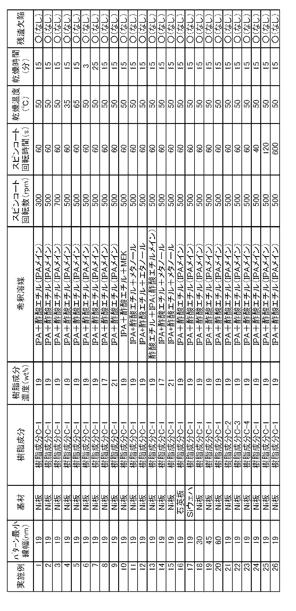
下記表4および表5は、それぞれ実施例および比較例の結果をまとめた表である。上記実施例1~26では、剥離性の高い保護膜が形成されていることから、保護膜を剥離しても残渣欠陥は生じなかった。一方、上記比較例1~14では残渣欠陥が生じた。具体的には、比較例1~4では、樹脂成分の弾性が低く保護膜の強度が不足して、アンカー効果に耐えきれず残渣欠陥が生じたと考えられる。比較例5および8では、保護膜の厚さが薄く保護膜の強度が不足して、アンカー効果に耐えきれず残渣欠陥が生じたと考えられる。比較例6では、樹脂成分の濃度が濃く基板と樹脂成分の相互作用が増大して残渣欠陥が生じたと考えられる。比較例7では、回転数が低く充分に塗料が基板上を拡がらず、保護膜が充分に硬化できないため残渣欠陥が生じたと考えられる。比較例9では、乾燥温度が低く保護膜が充分に乾燥しないため残渣欠陥が生じたと考えられる。比較例10では、乾燥温度が高く保護膜が乾燥しすぎて、接着力が増大し残渣欠陥が生じたと考えられる。比較例11では、樹脂成分の硬化不足により保護膜の強度が低下し残渣欠陥が生じたと考えられる。比較例12では、樹脂成分の被覆性が低く保護膜の強度が低下し残渣欠陥が生じたと考えられる。比較例13では、樹脂成分の接着力自体が弱いため残渣欠陥が生じたと考えられる。比較例14では、スピンコートの回転時間が足らず、保護膜厚みの不均一をきっかけとする硬化不足のため残渣欠陥が生じたと考えられる。また、スピンコートの回転時間が足らない場合、塗料の塗布ムラにより部分的に保護膜が形成されないといった問題も生じうる。
下記表4および表5は、それぞれ実施例および比較例の結果をまとめた表である。上記実施例1~26では、剥離性の高い保護膜が形成されていることから、保護膜を剥離しても残渣欠陥は生じなかった。一方、上記比較例1~14では残渣欠陥が生じた。具体的には、比較例1~4では、樹脂成分の弾性が低く保護膜の強度が不足して、アンカー効果に耐えきれず残渣欠陥が生じたと考えられる。比較例5および8では、保護膜の厚さが薄く保護膜の強度が不足して、アンカー効果に耐えきれず残渣欠陥が生じたと考えられる。比較例6では、樹脂成分の濃度が濃く基板と樹脂成分の相互作用が増大して残渣欠陥が生じたと考えられる。比較例7では、回転数が低く充分に塗料が基板上を拡がらず、保護膜が充分に硬化できないため残渣欠陥が生じたと考えられる。比較例9では、乾燥温度が低く保護膜が充分に乾燥しないため残渣欠陥が生じたと考えられる。比較例10では、乾燥温度が高く保護膜が乾燥しすぎて、接着力が増大し残渣欠陥が生じたと考えられる。比較例11では、樹脂成分の硬化不足により保護膜の強度が低下し残渣欠陥が生じたと考えられる。比較例12では、樹脂成分の被覆性が低く保護膜の強度が低下し残渣欠陥が生じたと考えられる。比較例13では、樹脂成分の接着力自体が弱いため残渣欠陥が生じたと考えられる。比較例14では、スピンコートの回転時間が足らず、保護膜厚みの不均一をきっかけとする硬化不足のため残渣欠陥が生じたと考えられる。また、スピンコートの回転時間が足らない場合、塗料の塗布ムラにより部分的に保護膜が形成されないといった問題も生じうる。
なお、実施例1~3の結果から、塗料の塗布をスピンコート法により実施する場合には、回転数は300~700rpmの範囲で調整可能であることがわかる。実施例2、4および5の結果から、乾燥温度は35~65℃の範囲で調整可能であることがわかる。実施例2、6および7の結果から、乾燥時間は3~25℃の範囲で調整可能であることがわかる。実施例2、8および9の結果から、樹脂成分濃度は17~21%の範囲で調整可能であることがわかる。実施例2および10~15の結果から、本発明の効果は希釈溶媒の種類に依存しないことがわかる。実施例2、16および17の結果から、本発明の効果は基板の材料に依存しないことがわかる。実施例2、18~20の結果から、本発明の効果は凹凸パターンの凹部の線幅に依存しないことがわかる。実施例2、6および7の結果から、有機イソシアネート中のイソシアネート基(NCO基)と活性水素含有化合物中の活性水素(H)との比がNCO/H=5.5/1~20/1モル比の範囲で調整可能であることがわかる。実施例24~26の結果から、スピンコートの回転時間は40s以上の広い範囲で調整可能であることがわかる。なお、保護膜の生産性を考慮すると、回転時間は40~120sであることが好ましい。

また、上記の実施形態では、本発明を磁気転写用のモールドに適用した場合について説明したが、本発明はこれに限られず、インプリント用のモールド等(パターンドメディア用、半導体配線パターン形成用、光学素子用、バイオチップ用など)の基板にも適用することができる。
Claims (9)
- 微細な凹凸パターンを表面に有するモールドの前記表面を保護する保護膜の形成方法において、
有機イソシアネートおよび活性水素含有化合物が混合され、該有機イソシアネート中のイソシアネート基(NCO基)と前記活性水素含有化合物中の活性水素(H)とがNCO/H=5.5/1~20/1モル比の範囲で反応して得られたイソシアネート基末端プレポリマー(A液)と、芳香族ジアミン、ポリオール及び/又はポリエーテルアミン、並びに硬化触媒が混合されて得られたレジン(B液)とが混合されて得られた塗料を用意し、
前記凹凸パターンがある前記表面に前記塗料を塗布し、
塗布された前記塗料を乾燥させて、前記表面に保護膜を形成することを特徴とする保護膜の形成方法。 - 前記活性水素含有化合物の水酸基価が120以下であることを特徴とする請求項1に記載の保護膜の形成方法。
- 前記塗料中における樹脂成分の濃度が17~21%であることを特徴とする請求項1または2に記載の保護膜の形成方法。
- イソプロピルアルコール、酢酸エチル、メタノール、エタノールおよびメチルエチルケトンのうち少なくとも1つの溶媒を用いて前記塗料を希釈し、
希釈した前記塗料を前記表面に塗布することを特徴とする請求項1から3いずれかに記載の保護膜の形成方法。 - 回転数が300~700rpmであり、回転時間が40~120sである条件の下、スピンコート法により前記塗料を塗布することを特徴とする請求項1から4いずれかに記載の保護膜の形成方法。
- 加熱温度が35~65℃である条件の下、塗布された前記塗料を加熱して乾燥させることを特徴とする請求項1から5いずれかに記載の保護膜の形成方法。
- 前記凹凸パターンの凹部の幅が20nm以下であることを特徴とする請求項1から6いずれかに記載の保護膜の形成方法。
- 微細な凹凸パターンを表面に有するモールドと、
請求項1から7いずれかに記載の保護膜の形成方法により形成された保護膜とを備えたことを特徴とする保護膜付モールド。 - 微細な凹凸パターンを表面に有し、該表面を保護する保護膜を備えた保護膜付モールドの製造方法において、
前記微細な凹凸パターンを表面に有するモールドを製造し、
請求項1から7いずれかに記載の保護膜の形成方法により前記保護膜を形成することを特徴とする保護膜付モールドの製造方法。
Applications Claiming Priority (2)
| Application Number | Priority Date | Filing Date | Title |
|---|---|---|---|
| JP2010215095A JP2012066213A (ja) | 2010-09-27 | 2010-09-27 | 凹凸パターン形成面を保護する保護膜の形成方法、並びに、それを利用した保護膜付モールドおよび保護膜付モールドの製造方法 |
| JP2010-215095 | 2010-09-27 |
Publications (1)
| Publication Number | Publication Date |
|---|---|
| WO2012042839A1 true WO2012042839A1 (ja) | 2012-04-05 |
Family
ID=45892330
Family Applications (1)
| Application Number | Title | Priority Date | Filing Date |
|---|---|---|---|
| PCT/JP2011/005418 Ceased WO2012042839A1 (ja) | 2010-09-27 | 2011-09-27 | 凹凸パターン形成面を保護する保護膜の形成方法、並びに、それを利用した保護膜付モールドおよび保護膜付モールドの製造方法 |
Country Status (2)
| Country | Link |
|---|---|
| JP (1) | JP2012066213A (ja) |
| WO (1) | WO2012042839A1 (ja) |
Citations (2)
| Publication number | Priority date | Publication date | Assignee | Title |
|---|---|---|---|---|
| JPH0885717A (ja) * | 1994-09-16 | 1996-04-02 | Mitsui Toatsu Chem Inc | ウレタンエラストマーの製造方法 |
| JP2009129506A (ja) * | 2007-11-26 | 2009-06-11 | Fujifilm Corp | モールド構造体、及び該モールド構造体を用いたインプリント方法 |
-
2010
- 2010-09-27 JP JP2010215095A patent/JP2012066213A/ja not_active Withdrawn
-
2011
- 2011-09-27 WO PCT/JP2011/005418 patent/WO2012042839A1/ja not_active Ceased
Patent Citations (2)
| Publication number | Priority date | Publication date | Assignee | Title |
|---|---|---|---|---|
| JPH0885717A (ja) * | 1994-09-16 | 1996-04-02 | Mitsui Toatsu Chem Inc | ウレタンエラストマーの製造方法 |
| JP2009129506A (ja) * | 2007-11-26 | 2009-06-11 | Fujifilm Corp | モールド構造体、及び該モールド構造体を用いたインプリント方法 |
Also Published As
| Publication number | Publication date |
|---|---|
| JP2012066213A (ja) | 2012-04-05 |
Similar Documents
| Publication | Publication Date | Title |
|---|---|---|
| TWI389930B (zh) | Polyurethane foam and polishing pad | |
| CN102159609B (zh) | 研磨垫用双组分型尿烷树脂组合物、聚氨酯研磨垫、和聚氨酯研磨垫的制造方法 | |
| CN114222800A (zh) | 异氰酸酯系粘接剂 | |
| US7964653B2 (en) | Polyol composition for two-component curable abrasive foam, composition for two-component curable abrasive foam, abrasive foam, and method for producing abrasive foam | |
| US20040209554A1 (en) | Polishing material and method of polishing therewith | |
| CN101253022A (zh) | 研磨垫 | |
| CN117924644B (zh) | 一种抛光垫基材及其制备方法 | |
| CA2489384A1 (en) | Polyurethane/urea composition for coating cylindrical parts | |
| CN106167552A (zh) | 研磨垫及其制造方法 | |
| CN109311138A (zh) | 研磨垫、研磨垫的制造方法和研磨方法 | |
| KR20200079884A (ko) | 연마패드용 조성물, 연마패드 및 이의 제조방법 | |
| JP5877131B2 (ja) | ポリウレタン樹脂形成性組成物及びポリウレタン樹脂 | |
| TWI461450B (zh) | 研磨墊用2液型胺基甲酸酯樹脂組成物、使用它而成之聚胺基甲酸酯研磨墊、及聚胺基甲酸酯研磨墊之製法 | |
| JP5039328B2 (ja) | 一液湿気硬化型ポリウレタン組成物 | |
| WO2012042839A1 (ja) | 凹凸パターン形成面を保護する保護膜の形成方法、並びに、それを利用した保護膜付モールドおよび保護膜付モールドの製造方法 | |
| JP6023506B2 (ja) | 接着性向上剤及びそれを用いてなる接着剤 | |
| EP2639250B1 (en) | Urethane resin particles | |
| JPH0364314A (ja) | バインダーおよび磁気記録材料 | |
| JP3353502B2 (ja) | ポリウレタン樹脂の製造方法 | |
| KR19980080054A (ko) | 자기 기록 매체용 폴리우레탄 결합체 | |
| JPS59148127A (ja) | バインダ−および磁気記録材料 | |
| TWI461451B (zh) | 研磨墊用胺基甲酸酯樹脂組成物、聚胺基甲酸酯研磨墊及聚胺基甲酸酯研磨墊之製法 | |
| JP4650139B2 (ja) | ウレタンエマルジョンおよびそれを用いた水系ポリウレタン組成物 | |
| TWI819244B (zh) | 黏著劑、黏著片及光學構件 | |
| JPH0725976A (ja) | 潜在性硬化剤を含有するイソシアネート組成物の硬化方法 |
Legal Events
| Date | Code | Title | Description |
|---|---|---|---|
| 121 | Ep: the epo has been informed by wipo that ep was designated in this application |
Ref document number: 11828405 Country of ref document: EP Kind code of ref document: A1 |
|
| NENP | Non-entry into the national phase |
Ref country code: DE |
|
| 122 | Ep: pct application non-entry in european phase |
Ref document number: 11828405 Country of ref document: EP Kind code of ref document: A1 |