WO2012042773A1 - Electronic device - Google Patents
Electronic device Download PDFInfo
- Publication number
- WO2012042773A1 WO2012042773A1 PCT/JP2011/005233 JP2011005233W WO2012042773A1 WO 2012042773 A1 WO2012042773 A1 WO 2012042773A1 JP 2011005233 W JP2011005233 W JP 2011005233W WO 2012042773 A1 WO2012042773 A1 WO 2012042773A1
- Authority
- WO
- WIPO (PCT)
- Prior art keywords
- battery pack
- cover
- case
- battery
- projection
- Prior art date
Links
Images


Classifications
-
- H—ELECTRICITY
- H04—ELECTRIC COMMUNICATION TECHNIQUE
- H04M—TELEPHONIC COMMUNICATION
- H04M1/00—Substation equipment, e.g. for use by subscribers
- H04M1/02—Constructional features of telephone sets
- H04M1/0202—Portable telephone sets, e.g. cordless phones, mobile phones or bar type handsets
- H04M1/026—Details of the structure or mounting of specific components
- H04M1/0262—Details of the structure or mounting of specific components for a battery compartment
-
- Y—GENERAL TAGGING OF NEW TECHNOLOGICAL DEVELOPMENTS; GENERAL TAGGING OF CROSS-SECTIONAL TECHNOLOGIES SPANNING OVER SEVERAL SECTIONS OF THE IPC; TECHNICAL SUBJECTS COVERED BY FORMER USPC CROSS-REFERENCE ART COLLECTIONS [XRACs] AND DIGESTS
- Y02—TECHNOLOGIES OR APPLICATIONS FOR MITIGATION OR ADAPTATION AGAINST CLIMATE CHANGE
- Y02E—REDUCTION OF GREENHOUSE GAS [GHG] EMISSIONS, RELATED TO ENERGY GENERATION, TRANSMISSION OR DISTRIBUTION
- Y02E60/00—Enabling technologies; Technologies with a potential or indirect contribution to GHG emissions mitigation
- Y02E60/10—Energy storage using batteries
-
- Y—GENERAL TAGGING OF NEW TECHNOLOGICAL DEVELOPMENTS; GENERAL TAGGING OF CROSS-SECTIONAL TECHNOLOGIES SPANNING OVER SEVERAL SECTIONS OF THE IPC; TECHNICAL SUBJECTS COVERED BY FORMER USPC CROSS-REFERENCE ART COLLECTIONS [XRACs] AND DIGESTS
- Y10—TECHNICAL SUBJECTS COVERED BY FORMER USPC
- Y10T—TECHNICAL SUBJECTS COVERED BY FORMER US CLASSIFICATION
- Y10T292/00—Closure fasteners
- Y10T292/08—Bolts
- Y10T292/096—Sliding
- Y10T292/0969—Spring projected
- Y10T292/097—Operating means
- Y10T292/0977—Cam
- Y10T292/0982—Bolt blocking or disabling means
- Y10T292/0986—Discrete push or pull actuator
Definitions
- the present invention relates to an electronic device in which a battery is detachably housed in a housing portion of the device.
- Patent Document 1 a structure has been proposed in which the battery can be fixed securely when the cover is closed, but the battery can be easily removed although the battery does not come off immediately when the cover is opened.
- the battery housing portion 101 in the electronic device 100 described in Patent Document 1 includes an engagement claw 102 and an operation member 103.
- the engagement claw 102 protrudes from the first housing side surface 104 and engages with the engagement concave portion of the battery housed in the battery housing portion 101, and retracts from the first housing side surface 104 from the engagement concave portion It is pivotably connected to the support shaft so as to be pivotable between the separate unlocking positions.
- the operation member 103 is disposed on the outer surface 106 of the main body 105 facing the first housing side surface 104.
- the operating member 103 is swingably connected to the support shaft, and is movably connected along the support shaft so as to be movable between the lock position and the lock release position separated from each other.
- the engagement claw 102 is engaged with the engagement recess of the battery, whereby the battery accommodation holding state is formed. Also, by moving the operation member 103 from the lock position to the lock release position and further moving the operation member 103 in the direction away from the battery, the engagement claw 102 is disengaged from the engagement recess of the battery, and the battery can be removed. It becomes a state.
- the present invention has been made to solve the conventional problems, and it is an object of the present invention to provide an electronic device capable of reliably holding a battery pack when the battery pack is attached and easily taking it out when the battery pack is taken out. I assume.
- An electronic device includes a case, a concave battery housing portion provided in the case, a battery pack housed in the battery housing portion, and the battery housing portion to cover the battery housing portion.
- a cover attached to the case by sliding relative to the case from an attachment start position covering a portion of the battery accommodating portion to an attachment completion position covering the whole of the battery accommodating portion;
- a battery pack holding member provided on an inner surface of the housing portion and capable of projecting and retracting toward an end face of the battery pack and having a battery pack locking claw engageable on the upper surface of the battery pack;
- a restricting member provided on the case-side surface, for restricting the movement of the battery pack holding member by engaging with the battery pack engaging claw when the cover is in the mounting completion position.
- the electronic device includes an elastic member that biases the battery pack holding member toward the end face of the battery pack.
- the upper surface of the battery pack engagement claw is a downward slope facing the upper surface of the battery pack.
- the electronic device is provided with a locking recess provided at a position corresponding to the battery pack locking claw on the end face of the battery pack.
- the regulating member provided on the back of the cover is the battery
- the battery pack retaining member holding the battery pack is engaged with the battery pack retaining claw of the battery pack by retaining the upper surface of the pack, so the movement of the battery pack retaining member in the direction of disengaging the battery pack retaining claw is restricted
- the battery pack can be reliably prevented from dropping out of the battery housing.
- the regulating member is also moved to release the engagement with the battery pack locking claw, so that the battery pack holding member can be moved in the direction of releasing the battery pack locking claw. It is possible to provide an electronic device having an effect that the battery pack can be easily removed by removing the cover.
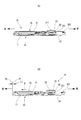
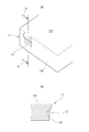
- (A) is a whole perspective view showing a state where a cover is attached to a case in a portable terminal of an embodiment according to the present invention
- (B) is a whole perspective view showing a state where a cover is slid and removed
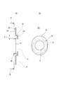
- (A) is a cross-sectional view showing a state in which the cover is attached to the case
- (B) is a cross-sectional view showing a state in which the cover is slid and removed
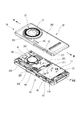
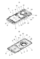
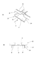
- An exploded perspective view showing the cover removed from the case (A) is a whole perspective view of a case
- (B) is a whole perspective view of the inner surface of a cover
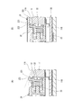
- A) is a cross section of the V-V position in FIG.
- (B) is a cross sectional view showing a state in which the battery pack holding member is restricted by the restriction member.
- (A) is a perspective view of the end face of the battery pack
- (B) is a cross-sectional view of the BB position in (A)
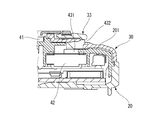
- (A) is a cross-sectional view at the position VII-VII in FIG. 4 (B)
- (B) is a cross-sectional view at the position BB in (A)
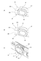
- A) is a perspective view which shows the relationship between an engagement protrusion, an abutting part, and a camera lens
- (B) is the front view seen from B direction in (A).
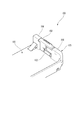
- FIG. 1 Cross-sectional view of the speaker mounting portion Perspective view of flash light
- A is a perspective view showing a state in which the cover is in the mounting completed position
- B is a perspective view showing the state in which the cover is in the mounting start position
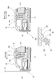
- A) is a perspective view showing the shutter switch when the cover is in the mounting completed position
- B) is a perspective view showing the shutter switch when the cover is in the mounting start position
- C is a wedge member View showing the relief part
- A) is a cross-sectional view of a state in which the cover is in the mounting start position at the XIII-XIII position in FIG.
- (B) is a cross-sectional view in the state of the cover being in the mounting completion position; ) Enlarged view of middle C part (A) is a side view of the first projection, and (B) is a front view as viewed from the direction B in (A) (A) is an enlarged view of the XV position in FIG. 3, (B) is an enlarged view of the XV position in FIG. 4 (A) A perspective view of a battery accommodating portion in a conventional electronic device
- a portable terminal 10 as an electronic device according to an embodiment of the present invention includes a case 20 having a rectangular box shape and a cover 30 covering the entire surface 201 of the case 20.
- the camera unit 40 is exposed from the camera opening 31 provided in the cover 30.
- a front cover (not shown) having a display plate, an operation part, etc. is attached to the side opposite to the cover 30 of the case 20. Further, in the following description, the upper side refers to the cover 30 side, and the lower side refers to the case 20 side.
- the case 20 is provided with a concave battery housing portion 21 opened on the cover 30 side, and the battery pack 11 is housed.
- the cover 30 is also a lid member that covers the battery housing portion 21.
- cover 30 When the cover 30 is attached to the case 20, as shown in FIG. 1B and FIG. 2B, the surface 30 of the case 20 at the attachment start position P1 covering the cover 30 and a part of the battery accommodating portion 21. Place on Then, with the relative position in the thickness direction with respect to case 20 maintained, that is, cover 30 is relatively slid backward (in the direction of arrow A in FIG. 2B) in parallel with surface 201 of case 20. It slides to the mounting completion position P0 which covers all of. Thus, the cover 30 is attached to the case 20 and covers the entire surface of the case 20. The sliding amount during this is the distance L1 between the mounting start position P1 and the mounting completion position P0 (see FIG. 1 (B)).
- a battery pack that can be projected and retracted toward the end face 11B of the battery pack 11 on the inner surface 211 of the battery housing 21 and holds the battery pack 11 A holding member 22 is provided.
- the battery pack holding member 22 has a battery pack locking claw 221 protruding in an inverted L shape upward and forward, and locks the upper surface 11A of the battery pack 11 .
- the upper surface 222 of the battery pack engagement claw 221 is a downward slope toward the upper surface 11 A of the battery pack 11 from the base end side to the tip end side of the battery pack engagement claw 221. Further, the battery pack holding member 22 is always urged toward the end face 11B of the battery pack 11 by the holding member spring 23 which is an elastic member.
- the battery pack holding member 22 is retracted along the inclined surface of the upper surface 222 to accommodate the battery pack 11. Then, when the battery pack 11 is moved to the lower side of the battery pack locking claw 221, the battery pack holding member 22 is pushed out by the holding member spring 23, and the battery pack locking claw 221 engages with the upper surface 11A of the battery pack 11. Stop.
- the battery pack engagement claw 221 is formed on the back surface 301 of the cover 30.
- a regulating member 32 which engages with. The restricting member 32 restricts movement of the battery pack holding member 22 in the state of holding the battery pack 11 in a direction away from the battery pack 11 (left side in FIG. 5B).
- the end face 11B of the battery pack 11 is located at a position corresponding to the battery pack locking claw 221 of the battery pack holding member 22 when the battery pack 11 is accommodated.
- the locking recess 12 is provided. Therefore, when removing the battery pack 11 from the battery containing portion 21, the battery pack 11 can be easily removed with one hand.
- the surface 201 of the case 20 is provided with a recess 24 (hereinafter referred to as a “camera recess 24”) that accommodates the camera unit 40.
- the camera opening 31 (see FIGS. 1A and 1B) is provided to face the camera recess 24.
- a frame member 33 as a circular cylinder is provided around the camera opening 31 on the surface 302 of the cover 30, a frame member 33 as a circular cylinder is provided.
- an edge rib 241 is provided upright as an edge along the edge.
- the camera unit 40 is accommodated in the camera recess 24, and the top of the camera lens 41 located at the tip of the camera unit 40 is disposed lower than the edge rib 241 (see FIG. 7A). .
- a lens movement concave portion 34 that protrudes to the front surface 302 side of the cover 30 is provided.
- the camera lens 41 and the edge rib 241 are accommodated inside the lens movement recess 34, and by sliding the cover 30 in the vertical direction in FIGS. 7A and 7B, the inside of the lens movement recess 34 is It moves relatively up and down.
- the lens moving recess 34 has an oval shape having a width that can accommodate the edge rib 241 and has a movable margin D.
- the lens movement concave portion 34 may not have an oval shape. As long as a space capable of accommodating the edge rib 241 can be secured, the shape may have a large circular shape or a linear portion. Therefore, even when the cover 30 is slid between the attachment start position P1 and the attachment completion position P0, the camera lens 41 seen from the camera opening 31 of the frame member 33 of the cover 30 always has a perfect circular shape. Can be kept good.
- an engagement protrusion 35 is provided at the central portion of the back surface 301 of the cover 30. Further, an abutting portion 36 (see FIG. 8B) which protrudes toward the case 20 beyond the tip end position of the engagement protrusion 35 is provided adjacent to the engagement protrusion 35.
- the abutment portions 36 are provided in a pair on both sides of the engagement projection 35.
- the L-shaped rib was provided as the contact part 36 here, it can also be set as rectangular flat form besides this, for example.
- the surface 201 of the case 20 is provided with an engagement hole 25 into which the engagement protrusion 35 is inserted when the cover 30 slides to the attachment completion position P0. ing.
- a speaker 42 is attached near the camera lens 41 in the case 20.
- the sound hole 431 is open.
- Crosspieces 434 are provided at two positions in the middle of the first sound hole 431, and the first sound hole 431 is divided into three.
- the second sound hole 432 communicating the inside and outside of the cover 30 and emitting the sound to the outside of the cover 30 is an attachment portion of the frame member 33 for the camera lens 41 to the cover 30.
- Crosspieces 435 are provided at two positions in the middle of the second sound hole 432 corresponding to the crosspiece 434, and the second sound hole 432 is divided into three.
- FIG. 4A when the sound hole wall portion 433 is formed on the surface 201 of the case 20 so as to surround the first sound hole 431 and the cover 30 is in the mounting completion position, The sound emitted from the first sound hole 431 is guided to the second sound hole 432.
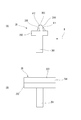
- the flash light 44 used when photographing with the camera unit 40 is exposed on the surface 302 of the cover 30.
- the flashlight 44 is attached to the surface 201 of the case 20, and at the corresponding position of the cover 30, an oval light hole 45 is provided.
- the flash light 44 includes, for example, a rectangular plate-shaped base layer 441 larger than the light hole 45, an oval-shaped intermediate layer 442 stacked on the base layer 441, and the intermediate layer 442 It has a light emitting layer 443 which is stacked and emits light.
- the base layer 441 preferably has a top surface formed of a color that reflects light such as silver, and is preferably a reflector. A circular opening is provided at a position facing above the light emitter 444 (see FIGS. 11A and 11B), and the light of the light emitter 444 is irradiated to the outside.
- the middle layer 442 is made of, for example, a transparent resin, and is hidden by the cover 30 when the cover 30 is at the attachment start position P1, and is exposed when in use when the cover 30 is at the attachment completion position P0.
- the light emitting layer 443 is integrally formed of a transparent resin with the intermediate layer 442, and has a corrugated surface on the surface to diffuse the light from the light emitting body 444 into a predetermined range.
- FIG. 11B when the cover 30 is at the attachment start position P1, a part of the base layer 441 is exposed from the light hole 45, and the intermediate layer 442 is hidden under the cover 30.
- FIG. 11A when the cover 30 is in use at the attachment completion position P0, the base layer 441 is not exposed to the light hole 45, and a part of the intermediate layer 442 is exposed from the light hole 45.
- the shutter switch 46 for operating the camera unit 40 to make the flash light 44 emit light is the case 20.
- An oblong wedge member 47 is provided on the side surface 202 of the case 20, and a shutter switch 46 is provided inside the wedge member 47 so as to be able to be pressed.
- an edge 371 is provided on the side surface 303 of the cover 30 corresponding to the shape of the wedge member 47, and a shutter switch notch 37 is provided inside the edge 371. ing.
- the shutter switch notch 37 has a shape in which the oval shape is substantially halved corresponding to the shape of the wedge member 47, and as shown in FIG. 12A, the cover 30 is in the mounting completed position P0 If not exposed. On the other hand, as shown in FIG. 12B, when the cover 30 is at the attachment start position P1, the shutter switch notch 37 is exposed to the outside of the wedge member 47.
- the covering member 47 is provided integrally with the covering material 471 exposed to the side surface 202 of the case 20 and the covering member 471 at the back of the covering material 471 and attached to the side surface 202 of the case 20. And an annular member 472.
- the outer peripheral surface of the cylindrical member 472 is recessed to the inside of the covering material 471 (left side in FIG. 12C)
- the part 473 is provided.
- a first protrusion 26 which can be protruded and retracted from the surface 201 of the case 20 is provided.
- FIG. 4B when the cover 30 slides between the attachment start position P1 and the attachment completion position P0, the first projection 26 is sunk on the back surface 301 of the cover 30.
- a second projection 38 is provided to pass through.
- the first protrusion 26 is vertically movably held inside the first protrusion guide portion 27 provided in the case 20, It is biased upward by a first projection spring 271 which is an elastic member.
- the first protrusion 26 has a column portion 261 on which the first protrusion spring 271 is wound, and a flat base provided on the top of the column portion 261. It has a portion 262 and a chevron shaped protrusion 263 provided on the base portion 262.
- the protrusion 263 contacts the second protrusion 38 when the cover 30 slides from the attachment start position P1 to the attachment completion position P0, that is, when the cover 30 slides in the attachment direction (see FIG. 13A).
- the first inclined surface 264 and the second projection 38 make contact when the cover 30 slides from the attachment completion position P0 to the attachment start position P1, that is, when the cover 30 slides in the dismounting direction (see FIG. 13B).
- a second attachment inclination that can make surface contact with the first attachment inclined surface 264 and the first removal inclined surface 265 of the first projection 26 respectively. It has a surface 381 and a second removal slope 382.
- the inclination angle ⁇ 1 of the first attachment inclined surface 264 with respect to the sliding direction of the cover 30 be an inclination angle gentler than the inclination angle ⁇ 2 of the first removal inclined surface 265.
- ⁇ 1 55 degrees
- ⁇ 2 about 70 degrees.
- the inclination angle of the second attachment inclined surface 381 be an inclination angle that is gentler than the inclination angle of the second removal inclined surface 382.
- the steeper the angle of the inclined surface the smaller the component force in the direction of pressing the first projection spring 271 when the cover 30 slides, so the force required for riding becomes larger, and the first projection is caused by the slide. 26 is easy to cut.
- the flatter the angle the smaller the force required to slide, and the more difficult the first protrusion 26 is to scrape. Therefore, it is desirable to flatten the angle when the biasing force of the first projection spring 271 is strong and to make the angle steep when the biasing force is weak.
- a tongue 39 is provided at the end of the back surface 301 of the cover 30, and as shown in FIG. 4A, the surface 201 of the case 20 is adjacent to the first protrusion 26.
- a tongue insertion portion 28 into which the tongue portion 39 is inserted when the cover 30 is at the attachment complete position P0.
- the arrangement of the tongue 39 and the tongue insertion portion 28 is not limited to this, and is arranged around the first protrusion 26 and before the first protrusion 26 contacts the second protrusion 38. As long as the tongue 39 is disposed at a position where it is inserted into the tongue insertion portion 28, it may be disposed at any position. Further, the set of the tongue 39 and the tongue insertion portion 28 is not limited to two, and may be one or three or more.
- the cover side wall 304 provided in the cover 30 along the sliding direction with respect to the case 20 is provided with a cover side wall protrusion 305 projecting toward the case 20 side. (See FIG. 4 (B)).
- a case side wall protrusion 204 which protrudes to the cover 30 side is provided on the case side wall 203 substantially parallel to the cover side wall 304 (see FIGS. 3 and 4A).
- the case side wall 203 is provided with a restricting protrusion 205 that protrudes toward the cover side wall 304.
- the restriction projection 205 on the cover side is provided at a position corresponding to the restriction projection 306 on the case 20 side, and prevents the contact between the cover side wall projection 305 and the case side wall projection 204 from being broken.
- the cover side wall projection 305 and the case side wall projection 204 abut each other to prevent rattling in the width direction (in the present embodiment, the width direction of the case 20).
- the distance between the cover side wall projection 305 and the case side wall projection 204 in the sliding direction is restricted by the restriction projection 205 and the restriction projection 306 so as to be equal to or less than a predetermined distance.
- the restricting protrusions 205 and the restricting protrusions 306 do not have to be in contact with each other in the state where the cover 30 is attached to the case 20, and as shown in FIG. 15A, a minute space may be provided. . Further, as shown in FIG. 15A, the restricting projections 205 and the restricting projections 306 respectively project to the vicinity of the cover 30 and the case 20. Therefore, like the cover side wall projections 305 and the case side wall projections 204, these restricting projections Also has the effect of restricting the position of the case 20 in the width direction.
- the projecting dimension of the restricting projection 205 is set smaller than the projecting dimension of the case sidewall projection 204. As a result, the restriction projection 205 can be prevented from coming into contact with the cover side wall projection 305 to stop the slide of the cover 30.
- the cover sidewall protrusion 305 and the case sidewall protrusion 204 have a convex curved surface.
- the shapes of the cover sidewall protrusion 305 and the case sidewall protrusion 204 are semicircular in cross section.
- the cover sidewall projection 305 and the case sidewall projection 204 move past each other while sliding on each other. It is desirable that the wear resistance of the first protrusion 26 be higher than the wear resistance of the cover side wall protrusion 305. Since this requires space for the first protrusion 26 in the thickness direction of the housing, the number and the position that can be arranged are limited so as not to interfere with the circuit board etc. inside the housing, whereas the cover sidewall protrusion 305 It is because these restrictions are thin and it is easy to arrange a plurality of projections in preparation for wear.
- the battery pack 11 is accommodated in the battery accommodating portion 21 and the cover 30 is slid from the attachment start position P1 to the attachment completion position P0.
- the cover 30 when the cover 30 is slid to the mounting start position P1, the regulating member 32 is also moved to release the engagement with the battery pack locking claw 221, so that the battery pack locking claw 221 of the battery pack holding member 22 is detached
- the cover 30 can be removed and the battery pack 11 can be easily removed.
- the engagement between the regulating member 32 and the battery pack engagement claw 221 is insufficient, the cover 30 can not be properly attached, so that it can be easily found that the attachment of the battery pack 11 is insufficient.
- the battery pack holding member 22 is urged toward the end face of the battery pack 11 by the holding member spring 23, the battery pack holding member 22 is pushed out toward the battery pack 11 when the battery pack 11 is accommodated. Thereby, the battery pack 11 can be reliably held.
- the battery pack 11 since a downward slope toward the top surface 11A of the battery pack 11 is provided on the top surface 222 of the battery pack engagement claw 221 from the base end side to the tip end side, the battery pack 11 is pushed into the battery housing portion 21. The battery pack locking claw 221 is retracted. Therefore, the battery pack 11 can be easily accommodated in the battery accommodating portion 21.
- the locking recess 12 is provided at a position corresponding to the battery pack locking claw 221 on the end face 11B of the battery pack 11, the battery pack locking claw 221 is retracted when taking out the battery pack 11.
- the finger can be put on the locking recess 12 to be easily taken out.
- the convex portion is provided in the vicinity of the locking concave portion 12, but this is also for achieving the same purpose.
- the locking recess 12 may not be provided, and only the protrusion may be provided, or only the locking recess 12 may be provided without providing the protrusion. That is, the locking recess does not necessarily have to be recessed as viewed from the entire other surface of the battery pack, and it is sufficient if it is relatively recessed.
- the engagement protrusion 35 provided at the center portion of the cover 30 on the case 20 side is the case Since it is inserted in the engagement hole 25 provided in the surface 201 of 20, floating of the central part of the cover 30 can be prevented.
- the camera lens 41 is disposed so that the top is at a lower position than the edge rib 241 of the camera recess 24 provided on the surface 201 of the case 20, and is provided adjacent to the engagement protrusion 35 of the cover 30.
- the abutting portion 36 protrudes toward the case 20 more than the tip end position of the engagement protrusion 35.
- the contact portion 36 abuts on the edge rib 241 of the camera recess 24, and the engagement protrusion 35 contacts the camera lens 41. As it does not reach, it is possible to reliably prevent the camera lens 41 from being damaged.
- the abutment portion 36 is provided as a pair across the engagement projection 35, when the force pressing the cover 30 against the case 20 acts, the abutment portion 36 abuts on the edge rib 241, and the engagement projection is formed. It is possible to reliably prevent the lens 35 from coming into contact with the camera lens 41 and damaging it.
- the camera concave portion 24 for housing the camera lens 41 is formed by an edge rib 241 which is a frame-like rib provided on the surface 201 of the case 20, and the tip end position of the edge rib 241 is a cover of the camera lens 41. Since the projection 30 is disposed on the cover 30 side more than the end face on the 30 side, when the engagement projection 35 is brought closer to the camera lens 41, the contact portion 36 contacts the tip surface of the edge rib 241. Therefore, the engagement projection 35 can be reliably prevented from coming into contact with the camera lens 41 and being damaged.
- the sound from the speaker 42 housed in the case 20 is emitted to the outside of the housing through the second sound hole 432 communicating the inside and outside of the cover 30, the sound hole can not be seen from the outer front of the cover 30, Don't lose.
- the second sound hole 432 can be provided independently of the attachment form of the cover 30 to the case 20.
- the sound hole wall portion 433 forming a substantially cylindrical communication path between the first sound hole 431 and the second sound hole 432 Since it is provided, it is possible to prevent sound pressure deterioration and sound omission.
- the second sound hole 432 is provided with the crosspiece 435 crossing the sound hole, the strength of the sound hole portion can be secured.
- the second sound hole 432 protrudes from the cover 30, a finger may be inserted into the second sound hole 432 when the cover 30 is removed, and an excessive force may be applied to the second sound hole 432 to cause damage. Therefore, by providing the crosspiece 435, it is possible to prevent the finger from entering the back of the second sound hole 432.
- the flashlight 44 provided on the surface 201 of the case 20 and protruding from the surface 201 is accommodated in the light hole 45 provided in the cover 30 from the attachment start position P1 to the attachment completion position P0.
- the flashlight 44 has a base layer 441, an intermediate layer 442 stacked on the base layer 441, and a light emitting layer 443 stacked on the intermediate layer 442.
- the base layer 441 is larger than the light hole 45.
- the middle layer 442 is concealed by the cover 30 when the cover 30 is at the attachment start position P1, and is exposed when the cover 30 is at the attachment completion position P0.
- the light emitting layer 443 is exposed from the light hole 45 when the cover 30 is at the mounting start position P1 and the mounting completion position P0.
- the intermediate layer 442 is exposed from the light hole 45 together with the light emitting layer 443 in the state where the cover 30 is at the attachment complete position P0. Since the intermediate layer 442 protrudes more than the base layer 441, the uncomfortable feeling of the step between the light emitting layer 443 and the exposed portion can be reduced as compared to the case where the base layer 441 is directly viewed.
- the cover 30 covering the predetermined area of the case 20 is an attachment completion position P0 covering the entire predetermined area from the attachment start position P1 covering a part of the predetermined area
- the case 20 is provided with a first projection 26 which can be protruded and retracted from the front surface 201 via a first projection spring 271.
- the cover 30 is attached to the attachment start position P1 and the attachment completion position
- a second projection 38 is provided which passes while sinking the first projection 26 when sliding between P0 and P0.
- the cover 30 by sliding the cover 30 repeatedly, the first protrusion 26 contacts the second protrusion 38 and repeatedly moves up and down, but the first protrusion 26 moves up and down by the elastic force of the first protrusion spring 271. Sufficient holding power can be maintained for a long time without deterioration of the resin.
- the first projection 26 When the cover 30 is attached by sliding the cover 30 from the attachment start position P1 to the attachment completion position P0, the first projection 26 contacts the second projection 38, but at this time, the first projection 26 is provided with the first projection 26. Since the second projection 38 moves along the mounting inclined surface 264, the first projection 26 can be smoothly pushed down. In addition, when the cover 30 is slid from the attachment completion position P0 to the attachment start position P1 and removed, the first protrusion 26 contacts the second protrusion 38, but at this time, the first protrusion 26 is provided on the first protrusion 26. Since the second projection 38 moves along the removal inclined surface 265, the first projection 26 can be smoothly pushed down, and the wear of the contact portion can be reduced.
- the second attachment 38 is configured to push down the first projection 26 by relatively sliding along the first attachment inclined surface 264 and the first removal inclined surface 265 provided on the first projection 26. Since the inclined surface 381 and the second removal inclined surface 382 are provided, the first protrusion 26 can be smoothly pushed down, and the wear of the contact portion can be reduced.
- the inclination angle ⁇ 1 of the first attachment inclined surface 264 contacting the second protrusion 38 when attaching the cover 30 is the second protrusion 38 when removing the cover 30.
- the cover 30 can be attached smoothly when the cover 30 is attached, and the cover 30 does not come off carelessly.
- a tongue 39 provided on the back of the cover 30 in the vicinity of the first projection 26 is a tongue insertion portion As it is inserted into the housing 28, the cover 30 can be prevented from being pushed up by the elastic force of the first projection spring 271 which pushes the first projection 26 toward the cover 30 side.
- cover 30 is mounted on the attachment start position P1 by cooperation of the cover side wall 304 provided on the cover 30 along the sliding direction with respect to the case 20 and the case side wall 203 provided on the case 20 substantially parallel to the cover side wall 304. Relative to the case 20 between the mounting position P0 and the mounting completion position P0.
- a cover side wall protrusion 305 is provided on the cover side wall 304, and a case side wall protrusion 204 is provided on the case side wall 203 to restrict movement of the cover 30 or the case 20 in the planar direction.
- the cover 30 and the case 20 shift even in a direction (for example, the width direction of the case 20) different from the sliding direction or in a direction in which it is difficult to perform position control with only the first protrusion 26 and the second protrusion 38 Can be prevented.
- the projections are provided on both the cover side wall 304 and the case side wall 203, but the projections may be provided on only one of them.
- cover side wall projection 305 and the case side wall projection 204 can be moved in sliding contact with each other at the time of sliding, whereby position control in the sliding direction can also be performed.
- the cover side wall projection 305 and the case side wall projection 204 may be worn by sliding contact, the wear resistance of the first projection 26 mechanically urged toward the case 20 by the first projection spring 271. If the resistance is set higher than the wear resistance of the resin cover sidewall protrusion 305 and the case sidewall protrusion 204, even if the resin cover sidewall protrusion 305 and the case sidewall protrusion 204 are worn, the first protrusion 26 and the case sidewall protrusion 204 are worn.
- Position control in the slide direction can be performed by the second projection 38, and it is possible to make it difficult to feel a change in the feeling of use.
- the cover sidewall protrusion 305 and the case sidewall protrusion 204 has a convex curved surface, the cover sidewall protrusion 305 and the case sidewall protrusion 204 at the time of sliding contact as compared with the case of using a protrusion having a straight portion. Can be suppressed.
- the case side wall 203 which is at least one of the inner surface of the cover side wall 304 and the case side wall 203, is provided with the control protrusion 205 projecting toward the other side.
- the distance in the sliding direction can be limited to a certain distance or less, and it is possible to prevent the occurrence of a deviation in a direction different from the sliding direction due to the cover sidewall protrusion 305 and the case sidewall protrusion 204 being separated from each other. be able to.
- the electronic device according to the present invention has been described above based on the embodiments. However, the present invention is not limited to the embodiments described above. In the embodiment described above, one set of the first protrusion 26 and the second protrusion 38 is provided, but the present invention is not limited to this. A plurality of sets may be provided.
- the cover side wall projection 305 and the case side wall projection 204 surmount each other as the cover 30 and the case 20 slide, but the present invention is not limited to this. It does not have to go over and may only contact each other. In this case, although the effect of performing the positional control in the sliding direction is reduced, it is possible to perform the positional control in the sliding direction even when the side wall projections are not in contact by the first projection 26 and the second projection 38. However, since the first projection 26 is configured to move up and down relatively easily, it is preferable to use the side wall projection to perform position control.
- the position restriction in the direction different from the sliding direction is performed by the cover side wall projection 305 and the case side wall projection 204, but the present invention is not limited thereto.
- the present invention is not limited thereto.
- position regulation in a direction different from the sliding direction can also be performed via the second projection 38.
- the edge rib 241 surrounds the entire circumference of the camera lens 41, but the present invention is not limited to this. Only a part of the camera lens 41 may be enclosed. That is, since it is sufficient for the edge rib 241 to surround only the range where the abutment portion 36 can abut when sliding, the edge rib 241 may not surround other portions.
- the engagement protrusion 35 is provided at the substantially central portion of the cover 30, but the present invention is not limited to this. It may be provided in another part, or may be provided in a plurality of places. However, it is desirable that the cover 30 be disposed substantially at the center in order to securely hold the cover 30 with less projections.
- the cover 30 and the case 20 were sliding, maintaining the relative position of the thickness direction, it is not restricted to this.
- the relative position of both may be changed at the time of sliding, such as sliding the cover 30 and the case 20 obliquely in the thickness direction.
- the crosspiece 435 is provided for the first sound hole 431, but the present invention is not limited to this.
- the first sound hole 431 may not be provided with a crosspiece.
- distortion etc. of a sound can be suppressed if the crosspiece corresponding to it is provided in the 1st sound hole 431.
- the application object of the present invention is not limited to the portable terminal. You may apply to another electronic device suitably.
- the electronic device of the present invention is not limited to the above-described embodiment, and appropriate modifications, improvements, and the like can be made.
Abstract
Description
図1(A)、(B)に示すように、本発明に係る実施形態の電子機器としての携帯端末10は、矩形箱状のケース20と、ケース20の表面201の全面を覆うカバー30とを有し、カバー30に設けられているカメラ用開口部31から、カメラユニット40が露出している。
なお、ケース20のカバー30とは反対側面には、表示板や操作部等を有する表カバー(図示省略)が取り付けられている。
また、以後の説明において、上側とはカバー30側をいい、下側とはケース20側をいう。 Hereinafter, an electronic device according to an embodiment of the present invention will be described using the drawings.
As shown in FIGS. 1A and 1B, a
A front cover (not shown) having a display plate, an operation part, etc. is attached to the side opposite to the
Further, in the following description, the upper side refers to the
また、電池パック保持部材22は、弾性部材である保持部材用スプリング23によって、電池パック11の端面11Bに向かって常時付勢されている。 As shown in FIG. 5A, the battery
Further, the battery
そして、電池パック11が電池パック係止爪221の下側に移動すると、電池パック保持部材22が保持部材用スプリング23により押し出されて、電池パック係止爪221が電池パック11の上面11Aを係止する。 Therefore, when the
Then, when the
規制部材32は、電池パック11を保持している状態にある電池パック保持部材22が、電池パック11から離れる方向(図5(B)において左側)への移動を規制する。 As shown in FIGS. 4B and 5B, when the
The restricting
従って、電池パック11を電池収容部21から取り外す際に、片手で、容易に電池パック11を取り外すことができる。 On the other hand, as shown in FIGS. 6A and 6B, the
Therefore, when removing the
一方、カメラユニット40はカメラ凹部24に収容され、カメラユニット40の先端に位置するカメラレンズ41の頂部が、縁リブ241よりも低く位置するように配置されている(図7(A)参照)。 In the
On the other hand, the
従って、カバー30を取付開始位置P1と取付完了位置P0との間でスライドさせても、カバー30の枠部材33のカメラ用開口部31から見えるカメラレンズ41は常に真円形状となるので、外観を良好に保つことができる。 The
Therefore, even when the
なお、ここでは、当接部36として、L字形状のリブを設けたが、この他、例えば矩形の平板状とすることもできる。
一方、図4(A)に示すように、ケース20の表面201には、カバー30が取付完了位置P0に摺動したときに、係合突起35が挿入される係合孔部25が設けられている。 As shown in FIGS. 4B and 8A, an
In addition, although the L-shaped rib was provided as the
On the other hand, as shown in FIG. 4A, the
図4(A)にも示すように、スピーカ42の上方に対応するケース20の表面201には、カメラレンズ41に隣接した位置にスピーカ42からの音をケース20の外部に放音する第1音孔431が開口している。第1音孔431の途中位置には桟434が2カ所設けられており、第1音孔431を三分割している。 As shown in FIG. 9, a
As also shown in FIG. 4A, on the
さらに、図4(A)に示すように、ケース20の表面201において、第1音孔431を囲うように音孔壁部433が形成されており、カバー30が取付完了位置にあるときに、第1音孔431から出た音を第2音孔432に導く。 Further, as shown in FIG. 4B, the
Further, as shown in FIG. 4A, when the sound
図3に示すように、フラッシュライト44はケース20の表面201に取り付けられており、カバー30において対応する位置には、長円形状をしたライト孔45が設けられている。 As shown in FIGS. 1A and 1B, the
As shown in FIG. 3, the
中間層442は、例えば透明な樹脂製であり、カバー30が取付開始位置P1にあるときにはカバー30に隠蔽されるとともに、カバー30が取付完了位置P0にある使用時には露出する。
発光層443は、中間層442と一体的に透明な樹脂で形成され、表面を波板状に形成して、発光体444からの光を所定の範囲に拡散する。 The
The
The
一方、図11(A)に示すように、カバー30が取付完了位置P0にある使用時には、ベース層441はライト孔45に露出しないで、中間層442の一部がライト孔45から露出する。 Therefore, as shown in FIG. 11B, when the
On the other hand, as shown in FIG. 11A, when the
ケース20の側面202には長円形状の鍔部材47が設けられており、鍔部材47の内部でシャッタースイッチ46が押圧可能に設けられている。
一方、図3に示すように、カバー30の側面303には、鍔部材47の形状に対応して縁部371が設けられており、縁部371の内側にはシャッタースイッチ用切欠37が設けられている。 As shown in FIGS. 1A and 1B and FIGS. 12A, 12B and 12C, the
An
On the other hand, as shown in FIG. 3, an
一方、図12(B)に示すように、カバー30が取付開始位置P1にある場合には、シャッタースイッチ用切欠37は鍔部材47の外側に露出する。 The
On the other hand, as shown in FIG. 12B, when the
一方、図4(B)に示すように、カバー30の裏面301には、カバー30が取付開始位置P1と前記取付完了位置P0との間を摺動するときに、第1突起26を沈ませながら通過する第2突起38が設けられている。 As shown in FIG. 4A, on the end side of the
On the other hand, as shown in FIG. 4B, when the
これにより、カバー30の取付時には容易にカバー30をスライドでき、カバー30の取外しの際には、取付時に比して力がいるので、不用意にカバー30が外れるのを防止できる。 As shown in FIG. 14A, it is desirable that the inclination angle θ1 of the first attachment inclined
As a result, the
なお、傾斜面の角度が急峻なほど、カバー30のスライド時に第1突起用スプリング271を押圧する方向への分力が小さくなるため、ライドに要する力が大きくなり、かつ、スライドによって第1突起26が削れ易くなる。一方、角度が平坦なほど、スライドに要する力が小さくなり、かつ、第1突起26が削れにくくなる。
そのため、第1突起用スプリング271の付勢力が強い場合には角度を平坦に、付勢力が弱い場合には角度を急峻にすることが望ましい。 In addition, as for the
The steeper the angle of the inclined surface, the smaller the component force in the direction of pressing the
Therefore, it is desirable to flatten the angle when the biasing force of the
これにより、カバー30が取付完了位置P0にあるときに、第1突起用スプリング271により上方へ付勢されている第1突起26が、第2突起38を介して、カバー30を押し上げるのを防止する。 As shown in FIG. 4B, a
As a result, when the
また、舌部39と舌挿入部28との組も2組には限られず、1組であってもよいし、3組以上あってもよい。 The arrangement of the
Further, the set of the
また、ケース20においてカバー側壁304と略平行なケース側壁203には、カバー30側に突出するケース側壁突起204が設けられている(図3および図4(A)参照)。 As shown in FIGS. 15A and 15B, the
Further, in the
なお、規制突起205の突出寸法は、ケース側壁突起204の突出寸法よりも小さく設定する。これにより、規制突起205がカバー側壁突起305に当接して,カバー30のスライドを停止させるのを防止できる。 The restricting
The projecting dimension of the restricting
なお、図15(A)、(B)においては、カバー側壁突起305およびケース側壁突起204の形状を半円断面としている。 In addition, in order to suppress wear of the protrusion at the time of sliding, it is desirable that at least one of the
In FIGS. 15A and 15B, the shapes of the
なお、第1突起26の耐摩耗性が、カバー側壁突起305の耐摩耗性よりも高いものとするのが望ましい。これは、第1突起26が筐体の厚み方向のスペースを要するため、筐体内部の回路基板等と干渉しないよう、配置できる数および位置が限定されるのに対し、カバー側壁突起305は、これらの制約が薄く、磨耗に備えて複数の突起を配置したりすることが容易であるためである。 Therefore, when the
It is desirable that the wear resistance of the
また、規制部材32と電池パック係止爪221との係合が不十分な場合には、カバー30が適正に取り付けられないので、電池パック11の取り付けが不十分であると容易に発見できる。 Further, when the
In addition, when the engagement between the regulating
なお、上述した実施形態では、係止凹部12の近傍に凸部を設けているが、これも同様の目的を達成するためのものである。また、係止凹部12を設けず、凸部のみを設けたり、凸部を設けず係止凹部12のみを設けるとしても良い。すなわち、係止凹部は、必ずしも電池パックの他の面全体から見て凹んでいる必要はなく、相対的に凹んでいれば十分である。近傍に凸部があれば相対的に指を掛けられる係止凹部が存在することとなるため、本明細書では、指掛けを行う部分の近傍に凸部のみを設けることも、係止凹部を設ける一手段であると見做す。 Furthermore, since the locking
In the embodiment described above, the convex portion is provided in the vicinity of the locking
また、カメラレンズ41は、頂部がケース20の表面201に設けられたカメラ凹部24の縁リブ241よりも低い位置となるように配置されており、カバー30の係合突起35に隣接して設けられた当接部36が、係合突起35の先端位置よりもケース20に向かって突出している。このため、カバー30をスライドさせる際に、何らかの力でカバー30をケース20に押し付けても、当接部36がカメラ凹部24の縁リブ241と当接して、係合突起35はカメラレンズ41に達しないので、カメラレンズ41を傷つけるのを確実に防止できる。 Moreover, according to the
Also, the
なお、第2音孔432は、ケース20に対するカバー30の取付形態に依存せずに設けることができる。 Further, since the sound from the
The
なお、第2音孔432はカバー30から突出しているため、カバー30の取り外し時に指が第2音孔432に挿入され、第2音孔432に無理な力がかかり破損する虞がある。そのため、桟435を設けることで、指が第2音孔432の奥に入り込むことを防ぐことも可能となる。 Further, since the
In addition, since the
従って、カバー30を繰り返しスライドすることにより、第1突起26は第2突起38に接触して上下に繰り返し移動するが、第1突起26は第1突起用スプリング271の弾性力により上下移動するため、樹脂の劣化を伴わず、十分な保持力を長期間維持できる。 Moreover, according to the
Therefore, by sliding the
また、カバー30を取付完了位置P0から取付開始位置P1にスライドさせて取り外す際に、第1突起26は第2突起38に接触するが、このとき、第1突起26に設けられている第1取外し傾斜面265に沿って第2突起38が移動するので、第1突起26をスムーズに押し下げることができ、接触部の摩耗を低減できる。 When the
In addition, when the
なお、カバー側壁突起305とケース側壁突起204とは、摺接によって磨耗する虞があるが、第1突起用スプリング271により機械的にケース20側に付勢されている第1突起26の耐摩耗性を、樹脂製のカバー側壁突起305およびケース側壁突起204の耐摩耗性よりも高くしておけば、樹脂製のカバー側壁突起305およびケース側壁突起204が磨耗しても、第1突起26および第2突起38によってスライド方向への位置規制を行うことができ、使用感の変化を感じにくくすることが出来る。 In addition, the cover
Although there is a possibility that the cover
以上、実施形態に基づいて本発明に係る電子機器を説明した。しかし、本発明は上述した実施形態に限られるものではない。
上述した実施形態では、第1突起26および第2突起38を1組設けていたがこれに限られるものではない。複数組設けるとしてもよい。 (Other modifications)
The electronic device according to the present invention has been described above based on the embodiments. However, the present invention is not limited to the embodiments described above.
In the embodiment described above, one set of the
このような構成にすれば、第2突起38を介してスライド方向と異なる方向の位置規制も行うことが可能となる。 Further, in the embodiment described above, the position restriction in the direction different from the sliding direction is performed by the cover
With such a configuration, position regulation in a direction different from the sliding direction can also be performed via the
なお、本発明の電子機器は、前述した実施形態に限定されるものでなく、適宜な変形,改良等が可能である。 Moreover, the application object of the present invention is not limited to the portable terminal. You may apply to another electronic device suitably.
The electronic device of the present invention is not limited to the above-described embodiment, and appropriate modifications, improvements, and the like can be made.
11 電池パック
11A 上面
11B 端面
12 係止凹部
20 ケース
21 電池収容部
211 内面
22 電池パック保持部材
221 電池パック係止爪
222 上面(傾斜面)
23 保持部材用弾性部材(弾性部材)
30 カバー
301 裏面
32 規制部材
P0 取付完了位置
P1 取付開始位置 10 Mobile terminal (electronic equipment)
DESCRIPTION OF
23 Elastic member for holding member (elastic member)
30
Claims (4)
- ケースと、
前記ケースに設けられた凹状の電池収容部と、
前記電池収容部に収容される電池パックと、
前記電池収容部を覆うために、前記電池収容部の一部を覆う取付開始位置から、前記電池収容部の全部を覆う取付完了位置まで、前記ケースに対して相対的に摺動することにより前記ケースに取り付けられるカバーと、
前記電池収容部の内面に設けられ、前記電池パックの端面に向かって突没可能であるとともに、前記電池パックの上面に係止可能な電池パック係止爪を有する電池パック保持部材と、
前記カバーの前記ケース側の面に設けられ、前記カバーが前記取付完了位置にあるときに、前記電池パック係止爪に係合することにより前記電池パック保持部材の移動を規制する規制部材と、を備える電子機器。 With the case,
A concave battery housing portion provided in the case;
A battery pack housed in the battery housing portion;
By sliding relative to the case from the mounting start position covering a part of the battery storage part to the mounting complete position covering the whole of the battery storage part in order to cover the battery storage part A cover attached to the case,
A battery pack holding member provided on an inner surface of the battery storage portion and capable of projecting and retracting toward an end face of the battery pack and having a battery pack locking claw engageable on the upper surface of the battery pack;
A restricting member provided on the case-side surface of the cover, for restricting the movement of the battery pack holding member by engaging the battery pack engaging claw when the cover is in the mounting completion position; An electronic device comprising the - 請求項1に記載の電子機器において、
前記電池パックの端面に向かって前記電池パック保持部材を付勢する弾性部材を備える電子機器。 In the electronic device according to claim 1,
An electronic device comprising: an elastic member which biases the battery pack holding member toward an end face of the battery pack. - 請求項1または請求項2に記載の電子機器において、
前記電池パック係止爪の上面が前記電池パックの上面に向かう下り傾斜面である電子機器。 In the electronic device according to claim 1 or 2,
The electronic device whose upper surface of the said battery pack latching claw is a downward inclined surface which goes to the upper surface of the said battery pack. - 請求項1ないし請求項3のうちのいずれか1項に記載の電子機器において、
前記電池パックの端面における前記電池パック係止爪に対応する位置に設けられた係止凹部を備える電子機器。 The electronic device according to any one of claims 1 to 3.
The electronic device provided with the latching recessed part provided in the position corresponding to the said battery pack latching claw in the end surface of the said battery pack.
Priority Applications (2)
| Application Number | Priority Date | Filing Date | Title |
|---|---|---|---|
| CN2011900003461U CN202977551U (en) | 2010-09-28 | 2011-09-15 | Electronic device |
| US13/579,872 US8934220B2 (en) | 2010-09-28 | 2011-09-15 | Electronic device |
Applications Claiming Priority (2)
| Application Number | Priority Date | Filing Date | Title |
|---|---|---|---|
| JP2010217661A JP5409573B2 (en) | 2010-09-28 | 2010-09-28 | Electronics |
| JP2010-217661 | 2010-09-28 |
Publications (1)
| Publication Number | Publication Date |
|---|---|
| WO2012042773A1 true WO2012042773A1 (en) | 2012-04-05 |
Family
ID=45892268
Family Applications (1)
| Application Number | Title | Priority Date | Filing Date |
|---|---|---|---|
| PCT/JP2011/005233 WO2012042773A1 (en) | 2010-09-28 | 2011-09-15 | Electronic device |
Country Status (4)
| Country | Link |
|---|---|
| US (1) | US8934220B2 (en) |
| JP (1) | JP5409573B2 (en) |
| CN (1) | CN202977551U (en) |
| WO (1) | WO2012042773A1 (en) |
Cited By (2)
| Publication number | Priority date | Publication date | Assignee | Title |
|---|---|---|---|---|
| WO2014147970A1 (en) * | 2013-03-22 | 2014-09-25 | Necカシオモバイルコミュニケーションズ株式会社 | Portable terminal |
| JP2017151264A (en) * | 2016-02-24 | 2017-08-31 | 株式会社シグマ | Imaging apparatus |
Families Citing this family (14)
| Publication number | Priority date | Publication date | Assignee | Title |
|---|---|---|---|---|
| USD733109S1 (en) * | 2012-12-28 | 2015-06-30 | Nokia Corporation | Handset camera |
| USD774025S1 (en) * | 2012-12-28 | 2016-12-13 | Microsoft Mobile Oy | Handset rear cover |
| USD735703S1 (en) * | 2013-06-06 | 2015-08-04 | Microsoft Mobile Oy | Handset |
| US9535459B2 (en) * | 2013-06-13 | 2017-01-03 | Getac Technology Corporation | Snap-on battery and portable electronic device having the same |
| USD743382S1 (en) * | 2013-09-20 | 2015-11-17 | Panasonic Intellectual Property Management Co., Ltd. | Microphone |
| CN105830249B (en) * | 2013-12-25 | 2019-02-19 | 松下知识产权经营株式会社 | Shell, the electronic equipment of electronic equipment |
| USD770430S1 (en) * | 2014-04-10 | 2016-11-01 | Lg Electronics Inc. | Core for mobile phone |
| US10051161B2 (en) * | 2014-04-18 | 2018-08-14 | Samsung Electronics Co., Ltd. | Electronic device with zoom lens |
| USD771026S1 (en) * | 2014-04-25 | 2016-11-08 | Lg Electronics Inc. | Main body for mobile phone |
| KR20160023109A (en) | 2014-08-21 | 2016-03-03 | 삼성전자주식회사 | Electronic device capable of maintaining a contact of a battery with a terminal |
| USD788733S1 (en) * | 2015-02-09 | 2017-06-06 | Lg Electronics Inc. | Mobile phone |
| CN111017086B (en) * | 2019-12-04 | 2021-09-28 | 深圳市班玛智行科技有限公司 | Intelligent scooter system with expandable functions, system platform and method |
| JP1689971S (en) * | 2020-06-30 | 2021-07-12 | ||
| CN112234694B (en) * | 2020-10-29 | 2023-11-07 | 瑞声科技(南京)有限公司 | Electronic equipment capable of replacing battery without power failure |
Citations (5)
| Publication number | Priority date | Publication date | Assignee | Title |
|---|---|---|---|---|
| JPS513855Y1 (en) * | 1969-12-18 | 1976-02-04 | ||
| JPH0476245U (en) * | 1990-11-14 | 1992-07-03 | ||
| JPH1154098A (en) * | 1997-08-08 | 1999-02-26 | Saitama Nippon Denki Kk | Battery fixing structure |
| JP2005032726A (en) * | 2003-07-05 | 2005-02-03 | Lg Electronics Inc | Portable terminal device |
| JP2005050753A (en) * | 2003-07-31 | 2005-02-24 | Sony Corp | Battery holder and electronic apparatus |
Family Cites Families (3)
| Publication number | Priority date | Publication date | Assignee | Title |
|---|---|---|---|---|
| JP2003086160A (en) * | 2001-09-14 | 2003-03-20 | Matsushita Electric Ind Co Ltd | Portable electronic appliance and battery mounting device thereof |
| JP3925790B2 (en) | 2002-05-27 | 2007-06-06 | ソニー株式会社 | Battery attachment / detachment mechanism |
| JP4846692B2 (en) * | 2007-11-12 | 2011-12-28 | 富士通東芝モバイルコミュニケーションズ株式会社 | Information processing device |
-
2010
- 2010-09-28 JP JP2010217661A patent/JP5409573B2/en not_active Expired - Fee Related
-
2011
- 2011-09-15 CN CN2011900003461U patent/CN202977551U/en not_active Expired - Lifetime
- 2011-09-15 WO PCT/JP2011/005233 patent/WO2012042773A1/en active Application Filing
- 2011-09-15 US US13/579,872 patent/US8934220B2/en not_active Expired - Fee Related
Patent Citations (5)
| Publication number | Priority date | Publication date | Assignee | Title |
|---|---|---|---|---|
| JPS513855Y1 (en) * | 1969-12-18 | 1976-02-04 | ||
| JPH0476245U (en) * | 1990-11-14 | 1992-07-03 | ||
| JPH1154098A (en) * | 1997-08-08 | 1999-02-26 | Saitama Nippon Denki Kk | Battery fixing structure |
| JP2005032726A (en) * | 2003-07-05 | 2005-02-03 | Lg Electronics Inc | Portable terminal device |
| JP2005050753A (en) * | 2003-07-31 | 2005-02-24 | Sony Corp | Battery holder and electronic apparatus |
Cited By (2)
| Publication number | Priority date | Publication date | Assignee | Title |
|---|---|---|---|---|
| WO2014147970A1 (en) * | 2013-03-22 | 2014-09-25 | Necカシオモバイルコミュニケーションズ株式会社 | Portable terminal |
| JP2017151264A (en) * | 2016-02-24 | 2017-08-31 | 株式会社シグマ | Imaging apparatus |
Also Published As
| Publication number | Publication date |
|---|---|
| JP2012074222A (en) | 2012-04-12 |
| US20120314355A1 (en) | 2012-12-13 |
| CN202977551U (en) | 2013-06-05 |
| JP5409573B2 (en) | 2014-02-05 |
| US8934220B2 (en) | 2015-01-13 |
Similar Documents
| Publication | Publication Date | Title |
|---|---|---|
| WO2012042773A1 (en) | Electronic device | |
| JP2004302783A (en) | Card type communication terminal | |
| JP5218799B2 (en) | Cover and housing | |
| US20100328858A1 (en) | Cover latching assembly for electronic device | |
| US20150077958A1 (en) | Electronic apparatus | |
| US8481200B2 (en) | Battery cover | |
| JP5116823B2 (en) | Electronics | |
| JP4163288B2 (en) | Electronics | |
| JP6414880B2 (en) | Opening / closing lid locking device | |
| US20100188805A1 (en) | Cover releasing mechanisms | |
| JP2012073376A (en) | Electronic equipment | |
| JP2011150996A (en) | Portable electronic device | |
| JP2006127809A (en) | Connector device for card | |
| JP4804124B2 (en) | Portable electronic devices | |
| JP2009205802A (en) | Electronic equipment | |
| JP2009163927A (en) | Lock device of opening and closing lid | |
| JP2013110642A (en) | Portable terminal | |
| JP2006127810A (en) | Connector device for card | |
| JP4163287B2 (en) | Electronics | |
| JP2012018771A (en) | Electronic apparatus | |
| TWI446145B (en) | Battery cover structure | |
| JP2006179393A (en) | Electronic device | |
| JP2008263496A (en) | Imaging apparatus | |
| JP2015060903A (en) | Electronic equipment | |
| JP3180007U (en) | Data socket with automatic return dust cover |
Legal Events
| Date | Code | Title | Description |
|---|---|---|---|
| WWE | Wipo information: entry into national phase |
Ref document number: 201190000346.1 Country of ref document: CN |
|
| 121 | Ep: the epo has been informed by wipo that ep was designated in this application |
Ref document number: 11828340 Country of ref document: EP Kind code of ref document: A1 |
|
| WWE | Wipo information: entry into national phase |
Ref document number: 13579872 Country of ref document: US |
|
| NENP | Non-entry into the national phase |
Ref country code: DE |
|
| 122 | Ep: pct application non-entry in european phase |
Ref document number: 11828340 Country of ref document: EP Kind code of ref document: A1 |