WO2012036196A1 - Electrolysis electrode, positive electrode for producing ozone electrolysis, positive electrode for producing persulfate electrolysis, and positive electrode for chromium electrolytic oxidation - Google Patents
Electrolysis electrode, positive electrode for producing ozone electrolysis, positive electrode for producing persulfate electrolysis, and positive electrode for chromium electrolytic oxidation Download PDFInfo
- Publication number
- WO2012036196A1 WO2012036196A1 PCT/JP2011/070972 JP2011070972W WO2012036196A1 WO 2012036196 A1 WO2012036196 A1 WO 2012036196A1 JP 2011070972 W JP2011070972 W JP 2011070972W WO 2012036196 A1 WO2012036196 A1 WO 2012036196A1
- Authority
- WO
- WIPO (PCT)
- Prior art keywords
- electrode
- electrolysis
- noble metal
- metal
- electrode surface
- Prior art date
Links
Images


Classifications
-
- C—CHEMISTRY; METALLURGY
- C25—ELECTROLYTIC OR ELECTROPHORETIC PROCESSES; APPARATUS THEREFOR
- C25B—ELECTROLYTIC OR ELECTROPHORETIC PROCESSES FOR THE PRODUCTION OF COMPOUNDS OR NON-METALS; APPARATUS THEREFOR
- C25B11/00—Electrodes; Manufacture thereof not otherwise provided for
- C25B11/04—Electrodes; Manufacture thereof not otherwise provided for characterised by the material
- C25B11/051—Electrodes formed of electrocatalysts on a substrate or carrier
- C25B11/073—Electrodes formed of electrocatalysts on a substrate or carrier characterised by the electrocatalyst material
- C25B11/075—Electrodes formed of electrocatalysts on a substrate or carrier characterised by the electrocatalyst material consisting of a single catalytic element or catalytic compound
- C25B11/081—Electrodes formed of electrocatalysts on a substrate or carrier characterised by the electrocatalyst material consisting of a single catalytic element or catalytic compound the element being a noble metal
-
- C—CHEMISTRY; METALLURGY
- C25—ELECTROLYTIC OR ELECTROPHORETIC PROCESSES; APPARATUS THEREFOR
- C25B—ELECTROLYTIC OR ELECTROPHORETIC PROCESSES FOR THE PRODUCTION OF COMPOUNDS OR NON-METALS; APPARATUS THEREFOR
- C25B11/00—Electrodes; Manufacture thereof not otherwise provided for
- C25B11/04—Electrodes; Manufacture thereof not otherwise provided for characterised by the material
- C25B11/051—Electrodes formed of electrocatalysts on a substrate or carrier
- C25B11/055—Electrodes formed of electrocatalysts on a substrate or carrier characterised by the substrate or carrier material
- C25B11/057—Electrodes formed of electrocatalysts on a substrate or carrier characterised by the substrate or carrier material consisting of a single element or compound
- C25B11/061—Metal or alloy
-
- C—CHEMISTRY; METALLURGY
- C02—TREATMENT OF WATER, WASTE WATER, SEWAGE, OR SLUDGE
- C02F—TREATMENT OF WATER, WASTE WATER, SEWAGE, OR SLUDGE
- C02F1/00—Treatment of water, waste water, or sewage
- C02F1/46—Treatment of water, waste water, or sewage by electrochemical methods
- C02F1/461—Treatment of water, waste water, or sewage by electrochemical methods by electrolysis
- C02F1/467—Treatment of water, waste water, or sewage by electrochemical methods by electrolysis by electrochemical disinfection; by electrooxydation or by electroreduction
- C02F1/4672—Treatment of water, waste water, or sewage by electrochemical methods by electrolysis by electrochemical disinfection; by electrooxydation or by electroreduction by electrooxydation
-
- C—CHEMISTRY; METALLURGY
- C23—COATING METALLIC MATERIAL; COATING MATERIAL WITH METALLIC MATERIAL; CHEMICAL SURFACE TREATMENT; DIFFUSION TREATMENT OF METALLIC MATERIAL; COATING BY VACUUM EVAPORATION, BY SPUTTERING, BY ION IMPLANTATION OR BY CHEMICAL VAPOUR DEPOSITION, IN GENERAL; INHIBITING CORROSION OF METALLIC MATERIAL OR INCRUSTATION IN GENERAL
- C23C—COATING METALLIC MATERIAL; COATING MATERIAL WITH METALLIC MATERIAL; SURFACE TREATMENT OF METALLIC MATERIAL BY DIFFUSION INTO THE SURFACE, BY CHEMICAL CONVERSION OR SUBSTITUTION; COATING BY VACUUM EVAPORATION, BY SPUTTERING, BY ION IMPLANTATION OR BY CHEMICAL VAPOUR DEPOSITION, IN GENERAL
- C23C10/00—Solid state diffusion of only metal elements or silicon into metallic material surfaces
- C23C10/18—Solid state diffusion of only metal elements or silicon into metallic material surfaces using liquids, e.g. salt baths, liquid suspensions
- C23C10/20—Solid state diffusion of only metal elements or silicon into metallic material surfaces using liquids, e.g. salt baths, liquid suspensions only one element being diffused
- C23C10/22—Metal melt containing the element to be diffused
-
- C—CHEMISTRY; METALLURGY
- C25—ELECTROLYTIC OR ELECTROPHORETIC PROCESSES; APPARATUS THEREFOR
- C25B—ELECTROLYTIC OR ELECTROPHORETIC PROCESSES FOR THE PRODUCTION OF COMPOUNDS OR NON-METALS; APPARATUS THEREFOR
- C25B1/00—Electrolytic production of inorganic compounds or non-metals
- C25B1/01—Products
- C25B1/13—Ozone
-
- C—CHEMISTRY; METALLURGY
- C25—ELECTROLYTIC OR ELECTROPHORETIC PROCESSES; APPARATUS THEREFOR
- C25B—ELECTROLYTIC OR ELECTROPHORETIC PROCESSES FOR THE PRODUCTION OF COMPOUNDS OR NON-METALS; APPARATUS THEREFOR
- C25B1/00—Electrolytic production of inorganic compounds or non-metals
- C25B1/01—Products
- C25B1/28—Per-compounds
- C25B1/29—Persulfates
-
- C—CHEMISTRY; METALLURGY
- C25—ELECTROLYTIC OR ELECTROPHORETIC PROCESSES; APPARATUS THEREFOR
- C25B—ELECTROLYTIC OR ELECTROPHORETIC PROCESSES FOR THE PRODUCTION OF COMPOUNDS OR NON-METALS; APPARATUS THEREFOR
- C25B11/00—Electrodes; Manufacture thereof not otherwise provided for
- C25B11/04—Electrodes; Manufacture thereof not otherwise provided for characterised by the material
- C25B11/051—Electrodes formed of electrocatalysts on a substrate or carrier
- C25B11/073—Electrodes formed of electrocatalysts on a substrate or carrier characterised by the electrocatalyst material
- C25B11/091—Electrodes formed of electrocatalysts on a substrate or carrier characterised by the electrocatalyst material consisting of at least one catalytic element and at least one catalytic compound; consisting of two or more catalytic elements or catalytic compounds
- C25B11/093—Electrodes formed of electrocatalysts on a substrate or carrier characterised by the electrocatalyst material consisting of at least one catalytic element and at least one catalytic compound; consisting of two or more catalytic elements or catalytic compounds at least one noble metal or noble metal oxide and at least one non-noble metal oxide
-
- C—CHEMISTRY; METALLURGY
- C25—ELECTROLYTIC OR ELECTROPHORETIC PROCESSES; APPARATUS THEREFOR
- C25B—ELECTROLYTIC OR ELECTROPHORETIC PROCESSES FOR THE PRODUCTION OF COMPOUNDS OR NON-METALS; APPARATUS THEREFOR
- C25B11/00—Electrodes; Manufacture thereof not otherwise provided for
- C25B11/04—Electrodes; Manufacture thereof not otherwise provided for characterised by the material
- C25B11/051—Electrodes formed of electrocatalysts on a substrate or carrier
- C25B11/073—Electrodes formed of electrocatalysts on a substrate or carrier characterised by the electrocatalyst material
- C25B11/091—Electrodes formed of electrocatalysts on a substrate or carrier characterised by the electrocatalyst material consisting of at least one catalytic element and at least one catalytic compound; consisting of two or more catalytic elements or catalytic compounds
- C25B11/097—Electrodes formed of electrocatalysts on a substrate or carrier characterised by the electrocatalyst material consisting of at least one catalytic element and at least one catalytic compound; consisting of two or more catalytic elements or catalytic compounds comprising two or more noble metals or noble metal alloys
-
- C—CHEMISTRY; METALLURGY
- C25—ELECTROLYTIC OR ELECTROPHORETIC PROCESSES; APPARATUS THEREFOR
- C25D—PROCESSES FOR THE ELECTROLYTIC OR ELECTROPHORETIC PRODUCTION OF COATINGS; ELECTROFORMING; APPARATUS THEREFOR
- C25D11/00—Electrolytic coating by surface reaction, i.e. forming conversion layers
- C25D11/005—Apparatus specially adapted for electrolytic conversion coating
-
- C—CHEMISTRY; METALLURGY
- C25—ELECTROLYTIC OR ELECTROPHORETIC PROCESSES; APPARATUS THEREFOR
- C25D—PROCESSES FOR THE ELECTROLYTIC OR ELECTROPHORETIC PRODUCTION OF COATINGS; ELECTROFORMING; APPARATUS THEREFOR
- C25D11/00—Electrolytic coating by surface reaction, i.e. forming conversion layers
- C25D11/38—Chromatising
-
- C—CHEMISTRY; METALLURGY
- C25—ELECTROLYTIC OR ELECTROPHORETIC PROCESSES; APPARATUS THEREFOR
- C25D—PROCESSES FOR THE ELECTROLYTIC OR ELECTROPHORETIC PRODUCTION OF COATINGS; ELECTROFORMING; APPARATUS THEREFOR
- C25D17/00—Constructional parts, or assemblies thereof, of cells for electrolytic coating
- C25D17/10—Electrodes, e.g. composition, counter electrode
-
- C—CHEMISTRY; METALLURGY
- C01—INORGANIC CHEMISTRY
- C01B—NON-METALLIC ELEMENTS; COMPOUNDS THEREOF; METALLOIDS OR COMPOUNDS THEREOF NOT COVERED BY SUBCLASS C01C
- C01B2201/00—Preparation of ozone by electrical discharge
- C01B2201/20—Electrodes used for obtaining electrical discharge
- C01B2201/24—Composition of the electrodes
-
- C—CHEMISTRY; METALLURGY
- C02—TREATMENT OF WATER, WASTE WATER, SEWAGE, OR SLUDGE
- C02F—TREATMENT OF WATER, WASTE WATER, SEWAGE, OR SLUDGE
- C02F1/00—Treatment of water, waste water, or sewage
- C02F1/72—Treatment of water, waste water, or sewage by oxidation
- C02F1/78—Treatment of water, waste water, or sewage by oxidation with ozone
-
- C—CHEMISTRY; METALLURGY
- C02—TREATMENT OF WATER, WASTE WATER, SEWAGE, OR SLUDGE
- C02F—TREATMENT OF WATER, WASTE WATER, SEWAGE, OR SLUDGE
- C02F1/00—Treatment of water, waste water, or sewage
- C02F1/46—Treatment of water, waste water, or sewage by electrochemical methods
- C02F1/461—Treatment of water, waste water, or sewage by electrochemical methods by electrolysis
- C02F1/46104—Devices therefor; Their operating or servicing
- C02F1/46109—Electrodes
- C02F2001/46133—Electrodes characterised by the material
- C02F2001/46138—Electrodes comprising a substrate and a coating
Definitions
- the present invention relates to an anode for electrolysis. Specifically, in sterilization in food processing and medical settings, water treatment and sterilization of water and sewage and wastewater, cleaning in semiconductor device manufacturing process, generation of peroxides such as ammonium persulfate, hexavalent chromium (Cr (VI)) plating
- the present invention relates to an anode for electrolysis used for management of chromium ion concentration.
- bacteria such as Legionella bacteria adhere to the circulating water of air-conditioning equipment, and when these equipment are operated, these bacteria are discharged into the room from the air outlet and float in the air. Bacteria such as Legionella bacteria also propagate in the remaining hot water of home baths.
- Active oxygen, especially ozone is a substance with very strong oxidizing power.
- Ozone water in which ozone is dissolved is used for sterilization in food processing and medical facilities, water and sewage systems containing organic substances such as malonic acid and odorous geosmin, and bacteria. It is used in the field where ozone is required for cleaning and sterilization treatment such as water treatment and sterilization of waste water (general waste water, ballast water, etc.) and cleaning in the semiconductor device manufacturing process.
- a method of generating ozone water As a method of generating ozone water, a method of generating ozone in water by electrolysis of water is known. Similarly, peroxides such as ammonium persulfate are known as cleaning agents such as resist removers in the process of manufacturing semiconductor circuits, and sulfuric acid generated by active oxygen such as ozone generated by the electrolytic reaction of sulfuric acid in the manufacture thereof. An electrolytic oxidation reaction or a direct electrolytic reaction from sulfuric acid is used.
- an electrode in which a base such as a valve metal is coated with lead oxide or a platinum (Pt) solid electrode is used for commercial use.
- the former has environmental problems such as electrode life reduction due to peeling during electrolysis and the elution of harmful substances that adversely affect the human body, and the latter electrode is not only able to obtain sufficient electrode activity (oxygen overvoltage). Expensive and economical.
- an electrode composed of titanium (Ti) and platinum (Pt) is also generally known, but Pt-coated Ti is composed of lead oxide (PbO 2 ).
- valve metals such as Ti, zirconium (Zr), niobium (Nb), and tantalum (Ta), which are generally used as electrode substrates.
- Many valve metals are known to have ozone generating ability when used as an anode due to high oxygen overvoltage.
- the surface of the electrode made of the valve metal is oxidized by electrolysis, and the oxide layer becomes thick and becomes non-conductive, so that the function as the electrode is impaired and the electrode has a short life. Therefore, it is considered to use a thin Ta oxide layer as a dielectric on the electrode surface (WO2003 / 000957).
- the ozone generation efficiency is good at the initial stage of use, but the initial characteristics do not last long, and there is a problem that the electrode life cannot be sufficiently obtained.
- Patent Documents 1 to 3 an electrode in which a noble metal layer such as Pt is formed in an intermediate layer with the electrode substrate and a valve metal oxide layer (dielectric layer) such as Ti is sequentially formed on the surface area is reported.
- These electrodes have a problem that a thin layer must be formed and fired a plurality of times in order to form an intermediate layer and a surface layer, and there are many work steps.
- the adhesion between the noble metal layer and the valve metal oxide layer is not sufficient, the electrode surface properties at the electrolytic reaction interface change during use, and high electrolytic oxidation ability cannot be maintained for a long time. .
- a platinum ribbon is used as the anode for electrolysis used in the production of persulfates such as ammonium persulfate.
- persulfates such as ammonium persulfate.
- sufficient oxygen overvoltage cannot be obtained by electrolytic treatment using platinum ribbon, so the amount of electrode consumption increases due to severe electrolysis conditions, and electrode components consumed in the electrolytic solution are mixed as impurities, and electrode replacement There were inconveniences such as having to be performed frequently. Therefore, by using a base such as a valve metal, an intermediate layer having a hardly oxidizable metal such as a platinum group metal, and an electrode having a surface layer containing a valve metal oxide on the electrode surface, sulfate ions are contained.
- lead or a lead alloy has been used for an anode electrode used for Cr (VI) plating because of its high electrolytic oxidation ability.
- These anodes can oxidize Cr (III) to Cr (VI) and control the Cr ion concentration appropriately, but lead chromate precipitates in a large amount due to anodic dissolution during use, and lead compounds and lead ions are in the plating waste liquid.
- the ozone generating anode used for water electrolysis has the problem that the initial characteristics of high oxygen overvoltage do not last long and the electrode life cannot be sufficiently obtained.
- an electrode used for the production of persulfuric acid by electrolysis of an aqueous solution containing sulfate ions neither oxygen overvoltage nor electrode life is sufficient.
- the anode electrode for electrolysis in sulfuric acid solution used for Cr (VI) plating cannot control the Cr ion concentration sufficiently, such as control of the amount of additive and contamination of the chromium plating film by the additive. There are challenges.
- the present invention aims to provide a long-life electrode for electrolysis having a high electrode oxidation ability at a high oxygen overvoltage based on a novel interfacial reaction and a novel structure near the surface of the electrode made of noble metal and valve metal.
- the first aspect is formed by high-temperature heat treatment under a low oxygen partial pressure of 100 Pa or less, has an electrode surface layer made of a valve metal oxide film, and the layer immediately below the electrode surface layer excludes valve metal and silver (Ag).
- An electrode for electrolysis made of a noble metal, in which the noble metal is precipitated and dispersed in a crystal grain boundary of the valve metal, and the valve metal crystal within a range of 30 ⁇ m in the vertical depth direction from the electrode surface It is an aspect relating to an electrode for electrolysis, characterized in that it is elongated crystal grains in a vertical cross section from the surface, and the noble metal in the range of 10 ⁇ m in the vertical depth direction from the electrode surface is 5 atomic% or less.
- the second aspect relates to the electrode for electrolysis according to the first aspect, wherein the noble metal is a platinum group metal.
- the third aspect relates to the electrode for electrolysis according to the first aspect, wherein the noble metal is platinum (Pt), iridium (Ir), ruthenium (Ru), or palladium (Pd).
- the noble metal is platinum (Pt), iridium (Ir), ruthenium (Ru), or palladium (Pd).
- a fourth aspect relates to the electrode for electrolysis according to the first aspect, wherein the noble metal in the range of 10 ⁇ m in the vertical depth direction from the electrode surface is 0.01 to 5 atomic%.
- the fifth aspect relates to the electrode for electrolysis according to the first aspect, wherein the valve metal is titanium (Ti) or zirconium (Zr).
- the sixth aspect is the aspect of the electrode for electrolysis according to the first aspect, wherein the thickness of the valve metal oxide film on the surface in the vicinity of the electrode surface is in the range of 3 nm to 200 nm.
- the seventh aspect is an aspect of the electrode for electrolysis according to the first aspect used as an anode for generating ozone by electrolysis of an aqueous solution.
- the eighth aspect is an aspect of the electrode for electrolysis according to the first aspect used as an anode for generating persulfuric acid by electrolysis of an aqueous solution containing sulfate ions.
- a ninth aspect is for electrolysis according to the first aspect, wherein trivalent chromium (Cr (III)) in a chromium (Cr) plating bath is used as an anode for oxidizing to hexavalent chromium (Cr (VI)). Electrode.
- the electrode for electrolysis according to the present invention has a novel structure near the electrode surface made of a noble metal and a valve metal, a high oxygen overpotential based on a new interface reaction, and a high electrolytic oxidation ability, and is highly efficient over a long period of time.
- the electrode can stably perform an electrolytic reaction without deterioration.
- the interfacial reaction is promoted in the production of ozone, the production of persulfuric acid, the oxidation reaction for Cr ion concentration control in Cr (VI) plating and the anodic electrolysis of peroxide.
- this electrode for electrolysis can be used also as a cathode, and polarity switching is also possible.
- the structure in the vicinity of the electrode surface of the present invention is shown.
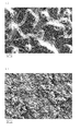
- Surface observation by scanning electron micrograph of electrode of the present invention (1200 ° C., 12 hours heat treatment) (a) and surface observation by scanning electron micrograph of electrode of Comparative Example 2 (heat treatment of 500 ° C., 24 hours) (heat treatment of 500 ° C., 24 hours) ( The figure which shows b).
- the electrode of the present invention is an electrode for electrolysis having a valve metal oxide electrode surface, and the base of the electrode surface is made of an alloy of a valve metal and a noble metal (excluding silver (Ag); the same applies hereinafter).
- the electrode surface is in contact with the interface responsible for the transfer of electrons accompanying the electrolytic reaction with the reactant in the aqueous solution (the surface is an oxide, and the nearby region is a metal).
- Valve metal oxides such as Ti and Zr have high oxygen overvoltage and have very high electrolytic oxidation ability such as ozone generation ability when used as an anode. Furthermore, since a passive oxide film exists on the electrode surface, high corrosion resistance can be obtained.
- the thick oxide film has no electrical conductivity, it loses the electrical conductivity of the electrode itself and cannot contribute to the electrolytic reaction.
- the valve metal crystal in the vicinity of the electrode surface near the electrode surface
- the precious metal in the range of 10 ⁇ m in the vertical depth direction from the electrode surface is 5 atomic% or less.
- the valve metal on the surface (electrode surface) in the vicinity of the electrode surface has an oxide film. It has been found that if such an electrode for electrolysis is used, efficient electrolysis can be performed for a long period of time without deteriorating the oxygen overvoltage without impairing the corrosion resistance and conductivity as compared with the conventional electrode.
- the valve metal crystals in the vicinity of the electrode surface are elongated grains in a vertical cross section from the electrode surface, the crystal grain boundaries exist uniformly in the electrode, and the noble metal contained in the electrode precipitates in the grain boundary. Is distributed. For this reason, even when the electrode is in use, the hardly oxidizable noble metal precipitated at the grain boundary prevents oxygen from entering the electrode through the grain boundary and suppresses the oxidation of the crystal grain, and also provides high electrical conductivity. Moreover, since the surface properties of the crystal grains and the electrodes are stably maintained by the noble metal contained in the crystal grain boundaries, an excellent electrolytic function can be exhibited continuously. Many precious metals are present in the grain boundaries, but are also present in the valve metal crystal lattice.
- the surface properties of the crystal grains and the electrode can be kept more stable by the noble metal in the crystal grains, and a more excellent electrolytic function can be continuously exhibited.
- This structure functions as an electrode for electrolysis without impairing conductivity and having excellent corrosion resistance.
- the valve metal on the electrode surface has an oxide film, a high oxygen overvoltage is obtained, and since the region near the electrode surface has the previous structure, electrons move smoothly, so efficient electrolysis can be performed. Can be done for a long time.
- the noble metal in the electrode for electrolysis of the present invention is 5 atomic% or less within a range of 10 ⁇ m in the vertical depth direction from the electrode surface.
- a noble metal content within a range of 10 ⁇ m in the vertical depth direction from the electrode surface is preferably used at 0.01 to 5 atomic%. If the noble metal content is too small, it may be difficult to prevent oxygen from entering the crystal grain boundaries or the grains and to suppress the progress of oxidation of the valve metal, which may impair electrical conductivity. More preferably, it is used in an amount of 0.1 to 5 atom%, and most preferably 0.3 to 3 atom%.
- the elongated crystal grains are crystal grains as shown in the electrode cross-sectional view of FIG.
- the grain boundary between the elongated crystal grains is 3 or more within a range of 30 ⁇ m in the vertical depth direction from the electrode surface. More preferably, it is 3-30.
- the area near the electrode surface of the present invention may be all or a part of the electrode, but it is preferably 10 ⁇ m or more in the depth direction from the electrode surface.
- the noble metal that constitutes the electrode for electrolysis of the present invention has excellent corrosion resistance and conductivity, and may be a noble metal alone or a noble metal alloy (including an oxide).
- a platinum group metal is used suitably, More preferably, platinum (Pt), iridium (Ir), ruthenium (Ru), or palladium (Pd), and Pt is the most preferable.
- a noble metal alloy is used, an alloy of a noble metal and a non-noble metal may be used, but an alloy between noble metals is preferable.
- a combination of Pt and a platinum group metal Pt—Ir alloy, Pt—Rh alloy, Pt—Ru alloy, Pt—Pd alloy
- platinum oxide, iridium oxide, palladium oxide, and ruthenium oxide are preferably used.
- Silver (Ag) is not suitable because it can not only suppress the entry of oxygen but also corrodes during electrolysis.
- the valve metal used in the electrode for electrolysis of the present invention is a refractory metal that forms a passive oxide film by anodic oxidation of Ti, Zr, Nb, Ta, etc. and exhibits corrosion resistance, preferably, Ti or Zr is Ti is most suitable for practical use.
- the valve metal on the surface in the vicinity of the electrode surface has an oxide film.
- the oxide film is formed by oxidizing part or all of the valve metal exposed on the electrode surface.
- the thickness of the valve metal oxide film on the electrode surface is preferably 3 to 200 nm. The reason for being 3 nm or more is that if an oxide film having a thickness of about 3 nm is present during the electrolytic reaction, it functions sufficiently as an electrode. When it exceeds 200 nm, the electron transfer from the reaction interface to the inside of the electrode is hindered, and the efficiency of the electrolytic reaction may be reduced. Further, since the film stress increases and the oxide film is easily peeled off, the corrosion resistance and durability are lowered, which is not preferable.
- a thickness of 3 to 100 nm is used.
- a thickness of 3 to 100 nm is used.
- the film thickness is about 10 to 20 nm in gold, about 20 to 30 nm in brown, about 30 to 60 nm in blue, about 60 to 90 nm in yellow, about 90 to 120 nm in purple, and about 120 to 160 nm. It is green and pink at about 160-200nm.
- the electrode surface of the present invention has a contoured pattern as seen in the scanning electron micrograph of FIG.
- the electrode for electrolysis of the present invention is suitably used as an anode for electrolytic oxidation reaction for generating active oxygen such as ozone by electrolysis in an aqueous solution. This is because the electrode of the present invention has a high oxygen overvoltage, promotes ozone generation in the electrolysis of water, and has high corrosion resistance even under strong oxidation conditions due to ozone generation.
- the electrode for electrolysis of the present invention is suitably used as an anode for generating persulfuric acid by electrolysis of an aqueous solution containing sulfate ions.
- the electrode of the present invention has a high electrolytic oxidation ability that exceeds the oxidation ability necessary for generating oxygen by electrolysis of water in an aqueous solution containing sulfate ions and oxidizes sulfate ions to persulfate ions. In addition, it has sufficient corrosion resistance even in an acidic liquid.
- the electrode for electrolysis of the present invention is suitably used as an anode for Cr (IV) plating. This is because the electrode of the present invention has a high electrolytic oxidation ability to oxidize Cr (III) produced by the plating reaction to Cr (VI) in a Cr (IV) plating bath and has sufficient corrosion resistance. Because.
- a first step of coating a valve metal substrate with a noble metal the valve metal of the substrate is coated with the noble metal by heat treatment at a high temperature of 1000 to 1500 ° C. It is manufactured by a second step in which the exposed and exposed valve metal surface is oxidized to form a region near the electrode surface.
- a first step of coating a valve metal substrate with a noble metal the valve metal of the substrate is coated with the noble metal by heat treatment at 1000 to 1500 ° C. It is manufactured by a second step of passing and exposing, and a third step of forming the valve metal oxide film on the electrode surface by oxidizing the exposed valve metal surface.
- the valve metal used in the first step is a refractory metal which shows a corrosion resistance by forming a passive oxide film by anodic oxidation of Ti, Zr, Nb, Ta, etc., preferably, Ti or Zr is used. Considering practicality, Ti is optimal.
- the noble metal used in the first step has excellent corrosion resistance and conductivity, and may be a noble metal alone or a noble metal alloy (including an oxide). In the case of consisting only of a noble metal, a platinum group metal is preferably used, more preferably Pt, Ir, Ru or Pd, and most preferably Pt. When a noble metal alloy is used, an alloy of a noble metal and a non-noble metal may be used, but an alloy between noble metals is preferable.
- Pt and a platinum group metal Pt—Ir alloy, Pt—Rh alloy, Pt—Ru alloy, Pt—Pd alloy
- the noble metal oxide platinum oxide, iridium oxide, palladium oxide, and ruthenium oxide are preferably used.
- the noble metal coating method in the first step includes plating, a method of forming a noble metal film by vacuum deposition sputtering, a method of forming a noble metal film by vacuum deposition sputtering, a method of forming a noble metal film by thermal spraying or cladding, Examples thereof include a method in which a noble metal compound solution is applied or vapor-deposited (CVD) on a base material to form a noble metal film by thermal decomposition, and a method in which a noble metal paste is applied to a base material to form a noble metal film.
- plating or magnetron sputtering is preferably used. From the viewpoint of economy and productivity, the platinum group metal is more preferably coated by electroplating.
- the surface of the valve metal can be activated and a noble metal intermediate layer having good adhesion can be formed.
- the surface (electrode surface) can be formed.
- the thickness of the noble metal coating is preferably 0.01 ⁇ m to 10 ⁇ m, more preferably 0.1 ⁇ m to 10 ⁇ m. If it is thinner than 0.01 ⁇ m, the diffusion of the coated noble metal during the high-temperature heat treatment becomes a short time, and the non-conduction of the valve metal oxide film constituting the region near the electrode surface cannot be easily controlled.
- the precious metal present at the grain boundaries of the valve metal formed by the shortage may be insufficient, and sufficient corrosion resistance may not be obtained, resulting in a short life of the electrode.
- it is thicker than 10 ⁇ m, the exposure of the valve metal and the diffusion of the noble metal are insufficient even after heat treatment, and the noble metal tends to remain on the electrode surface, so that it is difficult to form a homogeneous film of bulk metal oxide.
- it is not preferable because it uses a large amount of noble metal economically.
- the thickness of the noble metal is 0.3 to 3 ⁇ m.
- the valve metal diffuses and passes through the coated noble metal film by thermal vibration, thereby forming an area near the electrode surface suitable for the electrolytic reaction and its surface (electrode surface). Is done.
- the exposed valve metal surface is easily oxidized and forms an oxide film when oxygen is present during high-temperature heat treatment. Further, it may be formed by oxygen existing at the time of cooling after heat treatment or at the time of storage after cooling. Oxidation during cooling and storage is performed by natural oxidation, natural oxidation in the atmosphere (at room temperature), or electrolytic oxidation during an electrolytic reaction.
- the noble metal coated with the valve metal base material diffuses into the electrode by the high-temperature heat treatment in the second step, and is precipitated at the grain boundaries of the bulk metal.
- the valve metal crystal in the vicinity of the electrode surface has elongated crystal grains, the noble metal in the range of 10 ⁇ m in the vertical depth direction from the electrode surface is 5 atomic% or less, It diffuses into the valve metal crystal grain boundary and the valve metal crystal lattice. Therefore, the hardly oxidizable noble metal deposited at the crystal grain boundary during use of the electrode prevents oxygen from entering the electrode through the grain boundary, and not only suppresses the oxidation of the crystal grain but also provides high electrical conductivity.
- the electrode of the present invention can be preferably produced if the high temperature heat treatment is within the range of 1000 ° C. ⁇ (1 to 24 hours) to 1500 ° C. ⁇ (0.5 to 12 hours).
- the temperature is lower than 1000 ° C., if it is not applied for a long time, it is not preferable because it does not sufficiently pass through the noble metal covered with the valve metal of the base material and is difficult to be exposed, and the diffusion of the noble metal into the electrode is insufficient. Thus, when the diffusion is insufficient, the structure becomes different from the valve metal structure of the present invention, and an efficient electrolytic reaction cannot be performed. If the temperature exceeds 1500 ° C., the performance does not change any more and the cost increases. If the temperature is raised too much, the valve metal becomes all liquid and it is difficult to form the preferred electrode structure of the present invention. More preferably, it is performed at 1100 ° C. ⁇ (1 to 20 hours) to 1300 ° C. ⁇ (1 to 15 hours).
- the surface of the electrode of the present invention has a contour pattern as seen in the scanning electron micrograph of FIG. 2-a (1200 ° C. ⁇ 12 hours, high temperature heat treatment).
- the obtained electrode surface has a fine concavo-convex pattern as seen in FIG.
- the electrode after the high-temperature heat treatment (second step) is immersed in an aqueous solution containing a conductive salt to form an anode for electrolysis, and a current of 0.001 A / cm 2 (square cm) or more is applied.
- a current of 0.001 A / cm 2 (square cm) or more is applied.
- the third step can be performed separately at the initial stage or before use in the intended electrolysis.
- the oxide film is formed by oxidizing part or all of the valve metal on the surface near the exposed electrode surface.
- the third step may be performed by forming an oxide film with a small amount of oxygen simultaneously with the high-temperature heat treatment in the second step and cooling after the heat treatment. Further, an oxide film may be formed by oxygen present during storage after cooling.
- Oxidation during cooling and storage is performed by natural oxidation or natural oxidation in the atmosphere (at room temperature).
- the oxidation reaction is likely to proceed due to the heat, so it is preferable to carry out at a low oxygen partial pressure that does not form an oxide film more than necessary, and oxidation is performed at an oxygen partial pressure of 100 Pa or less. It is preferable to make it.
- Exceeding 100 Pa is not preferable because the oxide film grows too much, resulting in poor electrical conductivity and peeling.
- the total pressure may be under reduced pressure, under atmospheric pressure, or under high pressure (hot press, HIP (hot isostatic pressing), etc.) as long as the oxygen partial pressure is within such a range.
- the oxygen partial pressure is 10 ⁇ 2 Pa or less. Optimally, it is carried out under reduced pressure (10 ⁇ 2 to 200 Pa) and an oxygen partial pressure of 10 ⁇ 2 Pa or less.
- the thickness of the valve metal oxide film on the electrode surface of the present invention is preferably 3 to 200 nm. When the thickness is less than 3 nm, sufficient performance cannot be obtained for the electrolytic reaction, and particularly in the electrolytic oxidation reaction, the oxygen overvoltage decreases, which is not preferable. When it exceeds 200 nm, the electron transfer from the reaction interface to the inside of the electrode is hindered, and the efficiency of the electrolytic reaction is lowered. Further, the film stress is increased, the oxide film is likely to be peeled off, and the corrosion resistance and durability are deteriorated. More preferably, it is in the range of 3 to 100 nm.
- a Ti substrate (length 70 mm, width 20 mm, thickness 1 mm) was Pt-plated and then heat-treated.
- Pt plating involves immersing a Ti substrate in an alkaline degreasing solution, degreasing, then removing the passive film on the surface of the Ti substrate with a hydrofluoric acid solution, and a plating solution having a Pt concentration of 20 g / L (trade name: Platinumate 100 Japan) Using a plating bath (manufactured by Electroplating Engineers Co., Ltd.), plating was performed at various thicknesses with stirring under conditions of pH 14, liquid temperature 85 ° C., and current density 2.5 A / dm 2 .
- the thicknesses of Pt plating were 0.1 ⁇ m, 0.5 ⁇ m, 1 ⁇ m, 3 ⁇ m, 5 ⁇ m, and 10 ⁇ m, respectively.
- the heat treatment was performed under a reduced pressure atmosphere (degree of pressure reduction: 100 Pa, oxygen partial pressure 1 ⁇ 10 ⁇ 4 Pa) at a temperature of 1000 to 1300 ° C. for 1 to 12 hours.
- the titanium oxide film on the electrode surface was visually observed. It had a glossy color. From this, it is presumed that the titanium oxide film is formed with a thickness of 10 to 30 nm. Further, when surface observation ( ⁇ 500) was performed using a scanning electron microscope (SEM), contour lines were observed on the electrode surface (FIG. 2-a). For comparison, a Pt plating thickness of 1 ⁇ m and an electrode that was heat-treated at 500 ° C. under reduced pressure for 12 hours were prepared and similarly observed by SEM. The pattern was uneven (FIG. 2-b).
- the electrode of the first embodiment subjected to the surface observation was subjected to hydrofluoric acid etching and then subjected to an electrode cross-sectional observation with an optical microscope. As a result, it was confirmed to have elongated crystal grains, and the vertical depth of 30 ⁇ m from the electrode surface was obtained. 10-20 grain boundaries were observed (FIG. 1-a). Further, in the platinum mapping analysis by the electron probe microanalyzer of the electrode cross section, it was observed that most of the used platinum was precipitated and uniformly dispersed in the grain boundaries (FIG. 1-b). Moreover, the presence of platinum was also confirmed in the valve metal crystal lattice although the amount was small.
- Pt in the range of 10 ⁇ m in the vertical depth direction from the electrode surface was 1 atomic%.
- the Pt content in the range of 10 ⁇ m in the vertical depth direction from the electrode surface by metal mapping analysis was measured. It was 2 atomic% at 3 ⁇ m and 3 atomic% at a plating thickness of 5 ⁇ m.
- the electrode potential was measured using the electrode produced in the first embodiment.
- the electrode for electrolysis according to the present embodiment is used as the working electrode (anode)
- the Pt / Ti electrode electrode obtained by plating Pt on the Ti substrate with a film thickness of 1 ⁇ m
- the counter electrode cathode
- the Ag / AgCl electrode is used as the reference electrode.
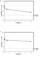
- Potentiometric measurements were taken. At that time, the solution was 1 M sulfuric acid (acid solution), the current was 1 mA, and the measurement equipment was an electrochemical measurement system (trade name: HZ-5000 series, manufactured by HOKUTO DENKO). The results are shown in FIGS.
- the oxygen overvoltage of the electrode of the first embodiment can be obtained by using a 0.1M sodium sulfate solution which is a neutral solution and a 0.1M sodium hydroxide solution which is an alkaline solution.
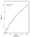
- the ozone generation ability evaluation of the electrode for electrolysis produced in the first embodiment (FIG. 5)
- the Pt plating thickness of the electrode for electrolysis produced in the first embodiment was set to 1 ⁇ m
- high-temperature heat treatment under reduced pressure (1200 ° C., 12
- Measurement of potential change at the time of ozone generation using the electrode for electrolysis (FIG. 6)
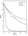
- the constant current treatment (FIGS. 7 and 8) of malonic acid and geosmin was performed using the electrode for electrolysis.
- the ozone generating ability was evaluated by measuring dissolved ozone over time.
- the electrode for electrolysis an electrode obtained by performing the high-temperature heat treatment of the first embodiment at 1100 ° C. (6 and 12 hours), 1200 ° C. (6 and 12 hours), and 1300 ° C. (1 hour) was used.
- the dissolved ozone is measured using a dissolved ozone meter (trade name: System-in-type ozone monitor EL-550, manufactured by Ebara Jitsugyo Co., Ltd.), electrolyte: 0.1 M sulfuric acid, anode: electrode for electrolysis of the present embodiment (area 10 cm 2 ), Current density: Measured by performing constant current treatment with stirring under the condition of 10 A / dm 2 .
- the potential change at the time of ozone generation is as follows: electrolyte: 0.1 M sulfuric acid, anode: electrode for electrolysis of this embodiment (Pt plating thickness is 1 ⁇ m, and electrode is subjected to high-temperature heat treatment at 1200 ° C. for 12 hours under reduced pressure. Area 10 cm 2 . ), Current density: measured by performing constant current treatment with stirring under the condition of 10 A / dm 2 . The results are shown in FIG. It was confirmed that the potential was stable at around 7.5 V after 3 minutes of energization and kept constant. Further, no decrease in potential was observed even when the measurement time was extended to 250 hours. This result shows that the electrode of the present invention can perform long-term stable electrolysis while maintaining a high oxygen overvoltage.
- the treatment conditions of the malonic acid treatment were as follows: treatment sample: malonic acid 3 mM, electrolyte: 0.1 M sodium sulfate, cathode: Pt / Ti electrode, current density: 5 A / dm 2 , temperature: 25 ° C. It was.
- the treatment conditions of the geosmin treatment were as follows: treatment sample: geosmin 500 ng / L, electrolyte: 0.1 M sodium sulfate, cathode: stainless steel electrode, current density: 5 A / dm 2 , temperature: 25 ° C. It was.
- FIG. 7 shows the result of constant current treatment of malonic acid using the electrode for electrolysis of this embodiment (Pt plating thickness is 1 ⁇ m, electrode for electrolysis heat-treated at 1300 ° C. for 1 hour under reduced pressure, area 12 cm 2 ).
- the results are compared with the results of an electrode (Pt / Ti) obtained by plating 1 ⁇ m of Pt on a Ti base material. From this result, it is apparent that the resolution of malonic acid was improved by using the electrode of the present invention because the decomposition amount of malonic acid increased with the treatment time.
- FIG. 8 shows a constant current treatment of geosmin using the electrode for electrolysis of this embodiment (Pt plating thickness is 1 ⁇ m, electrode for electrolysis heat-treated at 1300 ° C. for 1 hour under reduced pressure, area 12 cm 2 ).
- Pt plating thickness is 1 ⁇ m
- electrode for electrolysis heat-treated at 1300 ° C. for 1 hour under reduced pressure, area 12 cm 2 The result is compared with the result of an electrode (Pt / Ti) obtained by only plating 1 ⁇ m of Pt on a Ti base material.
- Pt plating thickness is 1 ⁇ m
- electrode for electrolysis heat-treated at 1300 ° C. for 1 hour under reduced pressure, area 12 cm 2 The result is compared with the result of an electrode (Pt / Ti) obtained by only plating 1 ⁇ m of Pt on a Ti base material.
- the result of simply stirring the geosmin-treated sample in the apparatus without performing electrolysis is shown in the figure as a control. From this result, it is clear that the resolution
- the electrode potential was measured about the electrode for electrolysis produced similarly to 1st Embodiment except having performed high-pressure heat processing (HIP processing) under high pressure instead of high-temperature heat processing under reduced pressure. .
- HIP processing high-pressure heat processing
- a Ti substrate (length 70 mm, width 20 mm, thickness 1 mm) was subjected to Ht treatment after Pt plating.
- Pt plating involves immersing a Ti substrate in an alkaline degreasing solution, degreasing, then removing the passive film on the surface of the Ti substrate with a hydrofluoric acid solution, and a plating solution having a Pt concentration of 20 g / L (trade name: Platinumate 100 Japan) Using a plating bath (manufactured by Electroplating Engineers Co., Ltd.), plating was performed with stirring under conditions of pH 14, liquid temperature 85 ° C., and current density 2.5 A / dm 2 .
- the thickness of the Pt plating was 0.01 ⁇ m, 0.1 ⁇ m, 1 ⁇ m, and 10 ⁇ m.
- the heat treatment was performed by HIP treatment for 1 hour under conditions of a temperature of 1350 ° C. and a pressure of 1 ⁇ 10 8 Pa in an Ar atmosphere. At this time, the oxygen partial pressure was 100 Pa.
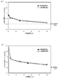
- the electrode potential was measured using 1M sulfuric acid or 0.1M sodium sulfate under the same conditions as in the first embodiment.
- FIG. 9 (a) is a diagram showing the results of measuring how much the electrode potential is different using the electrode for electrolysis of the second embodiment and using 1M sulfuric acid for the solution as in the first embodiment. Looking at the results, all the electrodes of the second embodiment are formed with electrodes having a higher oxygen overvoltage due to the increased potential as compared with the electrodes that were merely Pt plated and not subjected to high temperature heat treatment. I understand that. (And this tendency was observed not only when the solution was a 1M sulfuric acid solution but also when the solution was a neutral 0.1M sodium sulfate solution (see FIG. 9 (b)).
- the electrode for electrolysis similar to Embodiment 1 was produced except having used the base material of Zr metal instead of the base material of Ti metal, and the electrode potential was measured.
- the substrate made of Zr metal (length 70 mm, width 20 mm, thickness 1 mm) was removed with a hydrofluoric acid solution, Pt was plated with 1 ⁇ m, and heat treatment was performed under a reduced pressure atmosphere (degree of pressure reduction: 100 Pa, oxygen The partial pressure was 1 ⁇ 10 4 Pa) and the temperature was 1300 ° C. for 1 hour.
- the electrode potential of the prepared electrode was measured using 1M sulfuric acid for the solution by the same method as shown in the first embodiment.
- electrolysis was performed in a 1 M sulfuric acid solution at a current of 1 mA, and the electrode potential of the electrode of the third embodiment was measured and found to be 2.81 V.
- the potential was increased as compared with the electrode potential of 1.61 V, which was obtained by simply coating the Ti base material with 1 ⁇ m of Pt, and the electrode of the third embodiment also had a high oxygen overvoltage. .
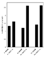
- an electrode for electrolysis similar to that of the first embodiment is prepared except that any of various platinum group metals (Ir, Ru, Pd) is coated instead of the coating by Pt plating, and the electrode potential is prepared. Was measured.
- Ti metal was used as a base material (length 70 mm, width 20 mm, thickness 1 mm), and any one of Ir, Ru and Pd was plated with a thickness of 1 ⁇ m.
- Ir plating is performed by immersing the Ti substrate in an alkaline degreasing solution and degreasing, and then removing the passive film on the surface of the Ti substrate with a hydrofluoric acid solution, and then plating solution (trade name: IRIDEX 200 Nippon Electroplating Engineers). Using a plating bath (manufactured by Co., Ltd.), plating was performed with stirring under conditions of a liquid temperature of 85 ° C. and a current density of 0.15 A / dm 2 .
- the Ti substrate is immersed in an alkaline degreasing solution, degreased, and then the passive film on the surface of the Ti substrate is removed with a hydrofluoric acid solution.
- the plating solution (trade name: Rutenex Nippon Electroplating Engineering Co., Ltd.) The plating was carried out with stirring under the conditions of a liquid temperature of 60 ° C. and a current density of 1 A / dm 2 .
- Pd plating the Ti substrate is immersed in an alkaline degreasing solution, degreased, and then the passive film on the surface of the Ti substrate is removed with a hydrofluoric acid solution.
- the plating solution (trade name: Paradex LF-2 Nippon Electroplating) -Using a plating bath manufactured by Engineers Co., Ltd., plating was performed with stirring under conditions of a liquid temperature of 60 ° C. and a current density of 2 A / dm 2 .
- the heat treatment was performed under a reduced pressure atmosphere (degree of pressure reduction: 100 Pa, oxygen partial pressure 1 ⁇ 10 ⁇ 4 Pa) at a temperature of 1000 ° C. for 7 hours.
- the electrode potential of the prepared electrode was measured using 1M sulfuric acid for the solution by the same method as shown in the first embodiment.
- electrolysis was performed in a 1 M sulfuric acid solution at a current of 1 mA, and the electrode potential of each of the electrodes for electrolysis of the fourth embodiment prepared by various platinum group metal (Ir, Ru, Pd) plating was determined.
- the measurement results are shown in FIG. This result shows that the potential is increased as compared with the electrode potential of the electrode obtained by simply coating the Ti base material with 1 ⁇ m of Ir, Ru, and Pd, and the electrode of the fourth embodiment also has a high oxygen overvoltage. It was.
- the same result is obtained also with the electrode produced from Rh plating.
- the present invention relates to an electrode for electrolysis having a long life and excellent ozone generation ability. And it has the electrode characteristic also with respect to various liquid liquids, and can be stably used for a long time as an electrode for electrolysis having high electrolytic oxidation ability. Thereby, ozone water used for cleaning sterilization processing etc. can be manufactured at low cost.
- the electrode according to the present invention it is possible to decompose a hardly decomposable organic substance such as malonic acid or geosmin.
- electrolytic persulfuric acid such as ammonium persulfate used for semiconductor cleaning, etc., by oxidation reaction from Cr (III) to Cr (VI) in the plating bath in Cr (VI) plating.
- the bath can be easily controlled.
Abstract
Description
また、電極寿命が十分得られないという問題がある。また、Pt被覆Ti合金を400~700℃で熱処理した電極やPt粉末とTi金属またはTi酸化物粉末との混合物で層を形成させた電極などが開発されている。しかし、オゾンの生成効率が低く消耗量が激しいなどの課題がある。 As an anode for generating ozone used for electrolysis of water, an electrode in which a base such as a valve metal is coated with lead oxide or a platinum (Pt) solid electrode is used for commercial use. However, the former has environmental problems such as electrode life reduction due to peeling during electrolysis and the elution of harmful substances that adversely affect the human body, and the latter electrode is not only able to obtain sufficient electrode activity (oxygen overvoltage). Expensive and economical. As described in
Further, there is a problem that the electrode life cannot be sufficiently obtained. In addition, an electrode in which a Pt-coated Ti alloy is heat-treated at 400 to 700 ° C., an electrode in which a layer is formed from a mixture of Pt powder and Ti metal or Ti oxide powder have been developed. However, there are problems such as low ozone generation efficiency and heavy consumption.
そこで、バルブ金属などの基体を用い、中間層に白金族金属などの難酸化性の金属を有し、電極表面にバルブ金属酸化物を含む表面層を有する電極を用いることで、硫酸イオンを含む水溶液を電解処理して過硫酸溶解水を生成する過硫酸溶解水の生成方法が考案されている(日本国特開2007-016303号公報)。しかし、その方法によっても、高い酸素過電圧を持続的に得られず電極寿命も短く、過硫酸の生成効率が不十分である。 For example, a platinum ribbon is used as the anode for electrolysis used in the production of persulfates such as ammonium persulfate. However, sufficient oxygen overvoltage cannot be obtained by electrolytic treatment using platinum ribbon, so the amount of electrode consumption increases due to severe electrolysis conditions, and electrode components consumed in the electrolytic solution are mixed as impurities, and electrode replacement There were inconveniences such as having to be performed frequently.
Therefore, by using a base such as a valve metal, an intermediate layer having a hardly oxidizable metal such as a platinum group metal, and an electrode having a surface layer containing a valve metal oxide on the electrode surface, sulfate ions are contained. A method for producing persulfate-dissolved water by electrolyzing an aqueous solution to produce persulfate-dissolved water has been devised (Japanese Patent Application Laid-Open No. 2007-016303). However, even by this method, a high oxygen overvoltage cannot be obtained continuously, the electrode life is short, and the production efficiency of persulfuric acid is insufficient.
かかる問題点を解決するために、白金族金属およびその酸化物を主成分とした不溶性電極を陽極に用いてめっきを行う方法がある。しかし、これらの陽極電極は鉛または鉛合金の陽極電極と比較してCr(III)からCr(VI)への酸化能が極めて低いため、めっき浴中のCrイオン濃度をコントロールすることが困難という問題点がある。
その解決策として、Tiを含む金属基体上に白金族金属を被覆した不溶性電極を使用し硝酸銀や酸化銀などの添加剤をめっき液に加えることで、Cr(VI)めっき中のCrイオン濃度を制御する方法が考案されている(日本国特開2006-131987号公報)。しかし、その方法を用いても十分なCrイオン濃度コントロールができず、添加剤量のコントロールや添加剤によるクロムめっき膜へのコンタミネーションなどの問題がある。 Conventionally, lead or a lead alloy has been used for an anode electrode used for Cr (VI) plating because of its high electrolytic oxidation ability. These anodes can oxidize Cr (III) to Cr (VI) and control the Cr ion concentration appropriately, but lead chromate precipitates in a large amount due to anodic dissolution during use, and lead compounds and lead ions are in the plating waste liquid. There is a problem such as mixing in.
In order to solve this problem, there is a method in which plating is performed using an insoluble electrode mainly composed of a platinum group metal and its oxide as an anode. However, these anode electrodes have extremely low oxidizing ability from Cr (III) to Cr (VI) as compared with lead or lead alloy anode electrodes, so it is difficult to control the Cr ion concentration in the plating bath. There is a problem.
As a solution, an insoluble electrode in which a platinum group metal is coated on a metal substrate containing Ti is used, and an additive such as silver nitrate or silver oxide is added to the plating solution, so that the Cr ion concentration during Cr (VI) plating can be reduced. A control method has been devised (Japanese Patent Laid-Open No. 2006-131987). However, even if this method is used, the Cr ion concentration cannot be sufficiently controlled, and there are problems such as control of the amount of additive and contamination of the chromium plating film by the additive.
本発明の電解用電極の第2の製造方法は、バルブ金属基材を貴金属により被覆する第1の工程、1000~1500℃の高温熱処理することにより前記基材のバルブ金属が前記貴金属の被覆を通過し表出させる第2の工程、前記表出させたバルブ金属表面が酸化され電極表面にバルブ金属酸化膜を形成する第3の工程により製造される。 In the first method for producing an electrode for electrolysis of the present invention, a first step of coating a valve metal substrate with a noble metal, the valve metal of the substrate is coated with the noble metal by heat treatment at a high temperature of 1000 to 1500 ° C. It is manufactured by a second step in which the exposed and exposed valve metal surface is oxidized to form a region near the electrode surface.
In the second method for producing an electrode for electrolysis according to the present invention, a first step of coating a valve metal substrate with a noble metal, the valve metal of the substrate is coated with the noble metal by heat treatment at 1000 to 1500 ° C. It is manufactured by a second step of passing and exposing, and a third step of forming the valve metal oxide film on the electrode surface by oxidizing the exposed valve metal surface.
上記第1の工程における貴金属の被覆方法は、めっきの他、真空蒸着スパッタリングにより貴金属膜を形成する方法、真空蒸着スパッタリングにより貴金属膜を形成する方法、溶射法やクラッドにより貴金属膜を形成する方法、貴金属化合物溶液を基材に塗布あるいは蒸着(CVD)し熱分解により貴金属膜を形成する方法、貴金属ペーストを基材に塗布して貴金属膜を形成する方法、等が挙げられる。簡便に均質な被覆を行うことを考慮すると、めっきまたはマグネトロンスパッタリングが好ましく用いられる。経済性・生産性の観点から、より好ましくは、電気めっきにより白金族金属が被覆される。電気めっきを行う場合は、バルブ金属表面のフッ酸などの薬品による化学的前処理やサンドブラストによる前処理を行うことが好ましい。それらの処理により、バルブ金属表面を活性化し、密着性の良好な貴金属中間層を形成でき、後の第2の工程の高温熱処理によるバルブ金属の表出において電解用電極に好ましい電極表面近傍域およびその表面(電極表面)を形成できる。尚、貴金属被覆の厚さは、好ましくは0.01μm~10μm、より好ましくは0.1μm~10μmである。0.01μmよりも薄いと、高温熱処理時の被覆された貴金属の拡散が短時間となり、電極表面近傍域を構成するバルブ金属酸化膜の不導態化を簡便に制御できなくなるばかりか、高温熱処理により形成されるバルブ金属の結晶粒界に存在する貴金属が不足し十分な耐食性が得られず電極が短寿命となる恐れがある。そして、10μmよりも厚いと、熱処理をしてもバルブ金属の表出と貴金属の拡散が不十分となり電極表面に貴金属が残りやすくなるため、バルク金属の酸化物の均質な膜が生成し難くなるばかりか、経済的にも貴金属を多く用いるため好ましくない。更に、貴金属の厚さを0.3~3μmとすれば最適である。 The valve metal used in the first step is a refractory metal which shows a corrosion resistance by forming a passive oxide film by anodic oxidation of Ti, Zr, Nb, Ta, etc., preferably, Ti or Zr is used. Considering practicality, Ti is optimal. Further, the noble metal used in the first step has excellent corrosion resistance and conductivity, and may be a noble metal alone or a noble metal alloy (including an oxide). In the case of consisting only of a noble metal, a platinum group metal is preferably used, more preferably Pt, Ir, Ru or Pd, and most preferably Pt. When a noble metal alloy is used, an alloy of a noble metal and a non-noble metal may be used, but an alloy between noble metals is preferable. Among these, a combination of Pt and a platinum group metal (Pt—Ir alloy, Pt—Rh alloy, Pt—Ru alloy, Pt—Pd alloy) is more preferable. As the noble metal oxide, platinum oxide, iridium oxide, palladium oxide, and ruthenium oxide are preferably used.
The noble metal coating method in the first step includes plating, a method of forming a noble metal film by vacuum deposition sputtering, a method of forming a noble metal film by vacuum deposition sputtering, a method of forming a noble metal film by thermal spraying or cladding, Examples thereof include a method in which a noble metal compound solution is applied or vapor-deposited (CVD) on a base material to form a noble metal film by thermal decomposition, and a method in which a noble metal paste is applied to a base material to form a noble metal film. In consideration of simple and uniform coating, plating or magnetron sputtering is preferably used. From the viewpoint of economy and productivity, the platinum group metal is more preferably coated by electroplating. When electroplating is performed, it is preferable to perform chemical pretreatment with a chemical such as hydrofluoric acid on the surface of the valve metal or pretreatment with sandblast. By these treatments, the surface of the valve metal can be activated and a noble metal intermediate layer having good adhesion can be formed. The surface (electrode surface) can be formed. The thickness of the noble metal coating is preferably 0.01 μm to 10 μm, more preferably 0.1 μm to 10 μm. If it is thinner than 0.01 μm, the diffusion of the coated noble metal during the high-temperature heat treatment becomes a short time, and the non-conduction of the valve metal oxide film constituting the region near the electrode surface cannot be easily controlled. As a result, the precious metal present at the grain boundaries of the valve metal formed by the shortage may be insufficient, and sufficient corrosion resistance may not be obtained, resulting in a short life of the electrode. If it is thicker than 10 μm, the exposure of the valve metal and the diffusion of the noble metal are insufficient even after heat treatment, and the noble metal tends to remain on the electrode surface, so that it is difficult to form a homogeneous film of bulk metal oxide. In addition, it is not preferable because it uses a large amount of noble metal economically. Furthermore, it is optimal if the thickness of the noble metal is 0.3 to 3 μm.
バルブ金属基材を被覆した貴金属は、第2の工程の高温熱処理により電極内部へ拡散し、バルク金属の粒界に析出される。このように製造された電極は、電極表面近傍域のバルブ金属結晶が細長の結晶粒を有し、電極表面から垂直深さ方向10μmの範囲内の貴金属が5原子%以下となり、また、貴金属はバルブ金属結晶粒界やバルブ金属結晶格子内へ拡散している。そのため、電極の使用中でも結晶粒界に析出した難酸化性の貴金属が、粒界を伝って電極内部へ進入する酸素を防ぎ、結晶粒の酸化を抑制するばかりか高い電気伝導性も得られる。また、結晶粒界に含まれる貴金属により結晶粒及び電極の表面性状が安定に保たれるため、優れた電解機能を持続的に発揮できる。更に、結晶粒内の貴金属により結晶粒及び電極の表面性状が更に安定に保たれ、より優れた電解機能を持続的に発揮できる。
高温熱処理は1000℃×(1~24時間)~1500℃×(0.5~12時間)の範囲内であれば本発明の電極を好適に製造できる。1000℃未満の場合は、長時間かけなければ、基材のバルブ金属が被覆された貴金属を十分に通過せず表出し難いばかりか、貴金属の電極内部への拡散も不十分となり好ましくない。このように拡散が不十分な場合には、本発明のバルブ金属組織と異なる組織となり、効率的な電解反応が行えない。また1500℃を超える場合は、それ以上性能に変化は無くコストが掛かってしまうばかりか、温度を上げすぎるとバルブ金属が全て液体になり本発明の好適な電極組織を形成し難くなる。より好ましくは、1100℃×(1~20時間)~1300℃×(1~15時間)で行われる。尚、本発明の電極表面は、図2-a(1200℃×12時間、高温熱処理)の走査型電子顕微鏡写真に見られるような等高線状の模様となるが、500℃×24時間の熱処理により得られる電極表面は、図2-bに見られるような細かな凹凸模様となる。 By the high-temperature heat treatment in the second step, the valve metal diffuses and passes through the coated noble metal film by thermal vibration, thereby forming an area near the electrode surface suitable for the electrolytic reaction and its surface (electrode surface). Is done. The exposed valve metal surface is easily oxidized and forms an oxide film when oxygen is present during high-temperature heat treatment. Further, it may be formed by oxygen existing at the time of cooling after heat treatment or at the time of storage after cooling. Oxidation during cooling and storage is performed by natural oxidation, natural oxidation in the atmosphere (at room temperature), or electrolytic oxidation during an electrolytic reaction.
The noble metal coated with the valve metal base material diffuses into the electrode by the high-temperature heat treatment in the second step, and is precipitated at the grain boundaries of the bulk metal. In the electrode manufactured in this way, the valve metal crystal in the vicinity of the electrode surface has elongated crystal grains, the noble metal in the range of 10 μm in the vertical depth direction from the electrode surface is 5 atomic% or less, It diffuses into the valve metal crystal grain boundary and the valve metal crystal lattice. Therefore, the hardly oxidizable noble metal deposited at the crystal grain boundary during use of the electrode prevents oxygen from entering the electrode through the grain boundary, and not only suppresses the oxidation of the crystal grain but also provides high electrical conductivity. Moreover, since the surface properties of the crystal grains and the electrodes are stably maintained by the noble metal contained in the crystal grain boundaries, an excellent electrolytic function can be exhibited continuously. Further, the surface properties of the crystal grains and the electrodes are further stably maintained by the noble metal in the crystal grains, and a more excellent electrolytic function can be continuously exhibited.
The electrode of the present invention can be preferably produced if the high temperature heat treatment is within the range of 1000 ° C. × (1 to 24 hours) to 1500 ° C. × (0.5 to 12 hours). When the temperature is lower than 1000 ° C., if it is not applied for a long time, it is not preferable because it does not sufficiently pass through the noble metal covered with the valve metal of the base material and is difficult to be exposed, and the diffusion of the noble metal into the electrode is insufficient. Thus, when the diffusion is insufficient, the structure becomes different from the valve metal structure of the present invention, and an efficient electrolytic reaction cannot be performed. If the temperature exceeds 1500 ° C., the performance does not change any more and the cost increases. If the temperature is raised too much, the valve metal becomes all liquid and it is difficult to form the preferred electrode structure of the present invention. More preferably, it is performed at 1100 ° C. × (1 to 20 hours) to 1300 ° C. × (1 to 15 hours). The surface of the electrode of the present invention has a contour pattern as seen in the scanning electron micrograph of FIG. 2-a (1200 ° C. × 12 hours, high temperature heat treatment). The obtained electrode surface has a fine concavo-convex pattern as seen in FIG.
本発明の電極表面のバルブ金属酸化膜の厚みは、3~200nmであることが好ましい。3nm未満の場合、電解反応に十分な性能が得られず、特に電解酸化反応においては酸素過電圧が低下するため好ましくない。200nmを超えると、反応界面から電極内部への電子移動が妨げられ、電解反応の効率が低下してしまう。また膜応力が大きくなり、酸化膜の剥離が生じやすく、耐食性や耐久性が低下してしまうため好ましくない。より好ましくは、3~100nmの範囲である。 In the third step, the electrode after the high-temperature heat treatment (second step) is immersed in an aqueous solution containing a conductive salt to form an anode for electrolysis, and a current of 0.001 A / cm 2 (square cm) or more is applied. As a result, the electrode surface is oxidized and an oxide film is formed. The third step can be performed separately at the initial stage or before use in the intended electrolysis. The oxide film is formed by oxidizing part or all of the valve metal on the surface near the exposed electrode surface. The third step may be performed by forming an oxide film with a small amount of oxygen simultaneously with the high-temperature heat treatment in the second step and cooling after the heat treatment. Further, an oxide film may be formed by oxygen present during storage after cooling. Oxidation during cooling and storage is performed by natural oxidation or natural oxidation in the atmosphere (at room temperature). When oxidizing at the time of heat treatment and cooling after the heat treatment, the oxidation reaction is likely to proceed due to the heat, so it is preferable to carry out at a low oxygen partial pressure that does not form an oxide film more than necessary, and oxidation is performed at an oxygen partial pressure of 100 Pa or less. It is preferable to make it. Exceeding 100 Pa is not preferable because the oxide film grows too much, resulting in poor electrical conductivity and peeling. The total pressure may be under reduced pressure, under atmospheric pressure, or under high pressure (hot press, HIP (hot isostatic pressing), etc.) as long as the oxygen partial pressure is within such a range. More preferably, the oxygen partial pressure is 10 −2 Pa or less. Optimally, it is carried out under reduced pressure (10 −2 to 200 Pa) and an oxygen partial pressure of 10 −2 Pa or less.
The thickness of the valve metal oxide film on the electrode surface of the present invention is preferably 3 to 200 nm. When the thickness is less than 3 nm, sufficient performance cannot be obtained for the electrolytic reaction, and particularly in the electrolytic oxidation reaction, the oxygen overvoltage decreases, which is not preferable. When it exceeds 200 nm, the electron transfer from the reaction interface to the inside of the electrode is hindered, and the efficiency of the electrolytic reaction is lowered. Further, the film stress is increased, the oxide film is likely to be peeled off, and the corrosion resistance and durability are deteriorated. More preferably, it is in the range of 3 to 100 nm.
Ti基材(縦70mm、横20mm、厚さ1mm)をPtめっきした後、加熱処理を行った。Ptめっきは、Ti基材をアルカリ性脱脂液に浸漬して脱脂後、フッ酸溶液にてTi基材表面の不動態皮膜を除去し、Pt濃度20g/Lのめっき液(商品名:プラチナート100 日本エレクトロプレイティング・エンジニヤース株式会社製)のめっき浴を用いて、pH14、液温85℃、電流密度2.5A/dm2の条件下で、撹拌しながら各種厚さでめっきした。Ptめっきの厚みは、それぞれ、0.1μm、0.5μm、1μm、3μm、5μm、10μmとした。加熱処理は、減圧雰囲気下(減圧度:100Pa、酸素分圧1×10-4Pa)、温度1000~1300℃にて1~12時間の条件で行った。 (First embodiment)
A Ti substrate (length 70 mm,
Tiを基材とし、Ptを0.1μmの厚さで電気めっきした後、テトラエトキシチタン溶液を用いスピンコート法により0.1μm程度のTi薄膜を形成し、大気雰囲気中600℃で焼成により電極表面のTiを酸化した電解用電極を用い、第1実施形態と同様の電極電位の測定を行ったが、測定中に表面の酸化Ti膜が剥離してしまった。 (Comparative Example 1)
After electroplating Pt with a thickness of 0.1 μm using Ti as a base material, a Ti thin film of about 0.1 μm is formed by spin coating using a tetraethoxy titanium solution, and the electrode is baked at 600 ° C. in an air atmosphere. Using the electrode for electrolysis in which Ti on the surface was oxidized, the same electrode potential as in the first embodiment was measured. However, the Ti oxide film on the surface was peeled off during the measurement.
Tiの無垢材を電極とし、第1実施形態と同様の電極電位の測定を行ったところ、通電時間の経過と共に電位は上昇し続け、4分後に不通となり電解用電極としての機能を失った(図6)。これは、短時間の電解によりTi表面に不導体膜が形成された為であると考えられる。 (Comparative Example 2)
When the electrode potential was measured in the same manner as in the first embodiment using a solid Ti material as the electrode, the potential continued to rise with the passage of the energization time, and after 4 minutes it was disconnected and lost its function as an electrode for electrolysis ( FIG. 6). This is presumably because a non-conductive film was formed on the Ti surface by short-time electrolysis.
第2実施形態では、減圧下高温熱処理の変わりに高圧下高温熱処理(HIP処理)を行ったこと以外は第1実施形態と同様に作成された電解用電極について、その電極電位の測定を行った。 (Second Embodiment)
In 2nd Embodiment, the electrode potential was measured about the electrode for electrolysis produced similarly to 1st Embodiment except having performed high-pressure heat processing (HIP processing) under high pressure instead of high-temperature heat processing under reduced pressure. .
第3実施形態では、Ti金属の基材の代わりにZr金属の基材を用いたこと以外は実施形態1と同様の電解用電極を作成し、その電極電位の測定を行った。 (Third embodiment)
In 3rd Embodiment, the electrode for electrolysis similar to
第4実施形態では、Ptめっきによる被覆の代わりに各種白金族金属(Ir、Ru、Pd)のいずれかを被覆したこと以外は、実施形態1と同様の電解用電極を作成し、その電極電位の測定を行った。 (Fourth embodiment)
In the fourth embodiment, an electrode for electrolysis similar to that of the first embodiment is prepared except that any of various platinum group metals (Ir, Ru, Pd) is coated instead of the coating by Pt plating, and the electrode potential is prepared. Was measured.
Claims (9)
- 100Pa以下の低酸素分圧下の高温熱処理により形成され、バルブ金属酸化膜からなる電極表面層を有し、該電極表面層の直下層がバルブ金属と銀(Ag)を除く貴金属からなり、前記バルブ金属の結晶粒界中に前記貴金属が析出し分散している電解用電極であって、
該電極表面から垂直深さ方向30μmの範囲内の前記バルブ金属の結晶が、電極表面から垂直断面において細長の結晶粒であり、電極表面から垂直深さ方向10μmの範囲内の前記貴金属が5原子%以下であることを特徴とする電解用電極。 Formed by high temperature heat treatment under a low oxygen partial pressure of 100 Pa or less, and having an electrode surface layer made of a valve metal oxide film, and a layer immediately below the electrode surface layer is made of a valve metal and a noble metal excluding silver (Ag), An electrode for electrolysis in which the noble metal is precipitated and dispersed in a crystal grain boundary of metal,
The crystal of the valve metal in the range of 30 μm in the vertical depth direction from the electrode surface is an elongated crystal grain in the vertical cross section from the electrode surface, and 5 atoms of the noble metal in the range of 10 μm in the vertical depth direction from the electrode surface. % Or less, an electrode for electrolysis. - 前記貴金属が白金族金属である請求項1に記載の電解用電極。 The electrode for electrolysis according to claim 1, wherein the noble metal is a platinum group metal.
- 前記貴金属が白金(Pt)、イリジウム(Ir)、ルテニウム(Ru)またはパラジウム(Pd)である請求項1に記載の電解用電極。 The electrode for electrolysis according to claim 1, wherein the noble metal is platinum (Pt), iridium (Ir), ruthenium (Ru), or palladium (Pd).
- 前記電極表面から垂直深さ方向10μmの範囲内の前記貴金属が0.01~5原子%である請求項1に記載の電解用電極。 2. The electrode for electrolysis according to claim 1, wherein the noble metal in the range of 10 μm in the vertical depth direction from the electrode surface is 0.01 to 5 atomic%.
- 前記バルブ金属がチタン(Ti)またはジルコニウム(Zr)である請求項1に記載の電解用電極。 The electrode for electrolysis according to claim 1, wherein the valve metal is titanium (Ti) or zirconium (Zr).
- 電極表面近傍域における表面のバルブ金属酸化膜の厚みが3nm以上200nm以下の範囲である請求項1に記載の電解用電極。 The electrode for electrolysis according to claim 1, wherein the thickness of the valve metal oxide film on the surface in the vicinity of the electrode surface is in the range of 3 nm to 200 nm.
- 水溶液の電解によりオゾンを生成するための陽極として用いる、請求項1に記載の電解用電極。 The electrode for electrolysis according to claim 1, which is used as an anode for generating ozone by electrolysis of an aqueous solution.
- 硫酸イオンを含む水溶液の電解により過硫酸を生成するための陽極として用いる、請求項1に記載の電解用電極。 The electrode for electrolysis according to claim 1, which is used as an anode for producing persulfuric acid by electrolysis of an aqueous solution containing sulfate ions.
- クロム(Cr)めっき浴中の三価クロム(Cr(III))を六価クロム(Cr(VI))へ酸化するための陽極として用いる、請求項1に記載の電解用電極。 The electrode for electrolysis according to claim 1, which is used as an anode for oxidizing trivalent chromium (Cr (III)) in a chromium (Cr) plating bath to hexavalent chromium (Cr (VI)).
Priority Applications (4)
| Application Number | Priority Date | Filing Date | Title |
|---|---|---|---|
| EP11825196.6A EP2617876B1 (en) | 2010-09-17 | 2011-09-14 | Electrolysis electrode, anode for electrolytic production of ozone or persulfate, and anode for electrolytic oxidation of chromium |
| KR1020137006635A KR101600147B1 (en) | 2010-09-17 | 2011-09-14 | Electrolysis electrode, positive electrode for producing ozone electrolysis, positive electrode for producing persulfate electrolysis, and positive electrode for chromium electrolytic oxidation |
| CN201180044792.7A CN103119205B (en) | 2010-09-17 | 2011-09-14 | Electrolysis electrode, generate for electrolysis ozone anode, generate the anode of persulfuric acid and the anode for electrolytic oxidation chromium for electrolysis |
| US13/823,877 US9353448B2 (en) | 2010-09-17 | 2011-09-14 | Electrolytic electrode, anode for electrolytic production of ozone, anode for electrolytic production of persulfuric acid and anode for electrolytic oxidation of chromium |
Applications Claiming Priority (2)
| Application Number | Priority Date | Filing Date | Title |
|---|---|---|---|
| JP2010-209763 | 2010-09-17 | ||
| JP2010209763A JP4734664B1 (en) | 2010-09-17 | 2010-09-17 | Electrode for electrolysis, anode for electrolysis of ozone, anode for electrolysis of persulfate, and anode for chromium electrooxidation |
Publications (1)
| Publication Number | Publication Date |
|---|---|
| WO2012036196A1 true WO2012036196A1 (en) | 2012-03-22 |
Family
ID=44461754
Family Applications (1)
| Application Number | Title | Priority Date | Filing Date |
|---|---|---|---|
| PCT/JP2011/070972 WO2012036196A1 (en) | 2010-09-17 | 2011-09-14 | Electrolysis electrode, positive electrode for producing ozone electrolysis, positive electrode for producing persulfate electrolysis, and positive electrode for chromium electrolytic oxidation |
Country Status (7)
| Country | Link |
|---|---|
| US (1) | US9353448B2 (en) |
| EP (1) | EP2617876B1 (en) |
| JP (1) | JP4734664B1 (en) |
| KR (1) | KR101600147B1 (en) |
| CN (1) | CN103119205B (en) |
| TW (1) | TWI493079B (en) |
| WO (1) | WO2012036196A1 (en) |
Cited By (1)
| Publication number | Priority date | Publication date | Assignee | Title |
|---|---|---|---|---|
| KR20170031233A (en) | 2014-08-19 | 2017-03-20 | 신닛테츠스미킨 카부시키카이샤 | Metal material and current-carrying component using said metal material |
Families Citing this family (7)
| Publication number | Priority date | Publication date | Assignee | Title |
|---|---|---|---|---|
| WO2013111788A1 (en) * | 2012-01-23 | 2013-08-01 | シャープ株式会社 | Water purification system and apparatus for producing antiseptic solution |
| JP6248448B2 (en) * | 2013-07-24 | 2017-12-20 | 株式会社リコー | Information processing apparatus and data storage control method thereof |
| KR101897567B1 (en) * | 2013-12-23 | 2018-09-13 | 코웨이 주식회사 | Cdi type water treatment apparatus |
| CN108473306B (en) * | 2016-01-28 | 2022-04-01 | 三菱电机株式会社 | Ozone supply device and ozone supply method |
| US11668017B2 (en) | 2018-07-30 | 2023-06-06 | Water Star, Inc. | Current reversal tolerant multilayer material, method of making the same, use as an electrode, and use in electrochemical processes |
| JP7370948B2 (en) * | 2020-08-28 | 2023-10-30 | マニー株式会社 | Black medical equipment and its manufacturing method |
| CN113213592A (en) * | 2021-05-27 | 2021-08-06 | 深圳市冠融辰环保科技有限公司 | Method for treating chromium electroplating cleaning wastewater |
Citations (11)
| Publication number | Priority date | Publication date | Assignee | Title |
|---|---|---|---|---|
| JPH02282491A (en) * | 1989-04-21 | 1990-11-20 | Daiso Co Ltd | Oxygen generating anode and production thereof |
| JPH0885894A (en) * | 1994-09-16 | 1996-04-02 | Tanaka Kikinzoku Kogyo Kk | Electrode |
| JP2001262385A (en) * | 2000-03-17 | 2001-09-26 | Matsushita Refrig Co Ltd | Electrolytic ozone generating device |
| WO2003000957A1 (en) | 2001-06-21 | 2003-01-03 | Sanyo Electric Co., Ltd. | Electrolyzing electrode and production method therefor and electrolysis method using electrolyzing electrode and electrolysis solution producing device |
| JP2005539135A (en) * | 2002-03-14 | 2005-12-22 | デ・ノラ・エレートローディ・ソチエタ・ペル・アツィオーニ | Anode for generating oxygen and support therefor |
| JP2006097122A (en) | 2004-08-31 | 2006-04-13 | Sanyo Electric Co Ltd | Electrode for electrolysis and method of manufacturing electrode for electrolysis |
| JP2006131987A (en) | 2004-10-08 | 2006-05-25 | Daiso Co Ltd | Chromium-plating method |
| JP2007016303A (en) | 2005-06-07 | 2007-01-25 | Sanyo Electric Co Ltd | Electrolyzing electrode and method for production of persulfuric acid-dissolving water by use of the electrode |
| JP2007046129A (en) | 2005-08-11 | 2007-02-22 | Sanyo Electric Co Ltd | Electrode for electrolysis, and method for producing electrode for electrolysis |
| JP2007224351A (en) | 2006-02-22 | 2007-09-06 | Sanyo Electric Co Ltd | Electrode for electrolysis, its production method and electrolytic method using the same |
| JP2010156034A (en) * | 2009-01-05 | 2010-07-15 | Japan Organo Co Ltd | Apparatus and method for producing persulfuric acid |
Family Cites Families (15)
| Publication number | Priority date | Publication date | Assignee | Title |
|---|---|---|---|---|
| LU36518A1 (en) * | 1957-10-24 | |||
| GB1113421A (en) * | 1964-07-20 | 1968-05-15 | Imp Metal Ind Kynoch Ltd | Electrodes and methods of making same |
| GB1327760A (en) * | 1969-12-22 | 1973-08-22 | Imp Metal Ind Kynoch Ltd | Electrodes |
| FR2088659A5 (en) * | 1970-04-21 | 1972-01-07 | Progil | |
| JPS5811000B2 (en) * | 1977-03-31 | 1983-02-28 | 新日本製鐵株式会社 | Manufacturing method of insoluble anode used for electrolysis of aqueous solution |
| EP0243302B1 (en) | 1986-04-17 | 1992-01-22 | Eltech Systems Corporation | An electrode with a platinum metal catalyst in surface film and its use |
| JPH0660427B2 (en) | 1988-05-31 | 1994-08-10 | ティーディーケイ株式会社 | Oxygen generating electrode and method for manufacturing the same |
| JPH06293998A (en) | 1993-04-08 | 1994-10-21 | Nippon Steel Corp | Insoluble iridium oxide coated electrode and its production |
| JP2003093479A (en) | 2001-07-18 | 2003-04-02 | Sanyo Electric Co Ltd | Sterilizing method and electrolyzed water producing device |
| TW539775B (en) * | 2001-12-31 | 2003-07-01 | Ind Tech Res Inst | Electrochemical catalyst electrode for reinforcing bonding durability between covering layer and metal substrate |
| MY136763A (en) * | 2003-05-15 | 2008-11-28 | Permelec Electrode Ltd | Electrolytic electrode and process of producing the same |
| DE10350727A1 (en) * | 2003-10-30 | 2005-06-02 | Mtu Aero Engines Gmbh | Component with a platinum-aluminum substrate area, platinum-aluminum coating and manufacturing process |
| CN100562606C (en) * | 2004-08-31 | 2009-11-25 | 三洋电机株式会社 | The manufacture method of electrode for electrolysis and electrode for electrolysis |
| JP2008095173A (en) * | 2006-09-13 | 2008-04-24 | Sanyo Electric Co Ltd | Electrode for electrolysis, electrolytic process using the electrode and electrolytic apparatus using them |
| CN101235513B (en) | 2007-11-14 | 2010-08-18 | 福州大学 | Coating titanium anode |
-
2010
- 2010-09-17 JP JP2010209763A patent/JP4734664B1/en active Active
-
2011
- 2011-09-14 US US13/823,877 patent/US9353448B2/en active Active
- 2011-09-14 KR KR1020137006635A patent/KR101600147B1/en active IP Right Grant
- 2011-09-14 CN CN201180044792.7A patent/CN103119205B/en active Active
- 2011-09-14 EP EP11825196.6A patent/EP2617876B1/en active Active
- 2011-09-14 WO PCT/JP2011/070972 patent/WO2012036196A1/en active Application Filing
- 2011-09-15 TW TW100133244A patent/TWI493079B/en active
Patent Citations (11)
| Publication number | Priority date | Publication date | Assignee | Title |
|---|---|---|---|---|
| JPH02282491A (en) * | 1989-04-21 | 1990-11-20 | Daiso Co Ltd | Oxygen generating anode and production thereof |
| JPH0885894A (en) * | 1994-09-16 | 1996-04-02 | Tanaka Kikinzoku Kogyo Kk | Electrode |
| JP2001262385A (en) * | 2000-03-17 | 2001-09-26 | Matsushita Refrig Co Ltd | Electrolytic ozone generating device |
| WO2003000957A1 (en) | 2001-06-21 | 2003-01-03 | Sanyo Electric Co., Ltd. | Electrolyzing electrode and production method therefor and electrolysis method using electrolyzing electrode and electrolysis solution producing device |
| JP2005539135A (en) * | 2002-03-14 | 2005-12-22 | デ・ノラ・エレートローディ・ソチエタ・ペル・アツィオーニ | Anode for generating oxygen and support therefor |
| JP2006097122A (en) | 2004-08-31 | 2006-04-13 | Sanyo Electric Co Ltd | Electrode for electrolysis and method of manufacturing electrode for electrolysis |
| JP2006131987A (en) | 2004-10-08 | 2006-05-25 | Daiso Co Ltd | Chromium-plating method |
| JP2007016303A (en) | 2005-06-07 | 2007-01-25 | Sanyo Electric Co Ltd | Electrolyzing electrode and method for production of persulfuric acid-dissolving water by use of the electrode |
| JP2007046129A (en) | 2005-08-11 | 2007-02-22 | Sanyo Electric Co Ltd | Electrode for electrolysis, and method for producing electrode for electrolysis |
| JP2007224351A (en) | 2006-02-22 | 2007-09-06 | Sanyo Electric Co Ltd | Electrode for electrolysis, its production method and electrolytic method using the same |
| JP2010156034A (en) * | 2009-01-05 | 2010-07-15 | Japan Organo Co Ltd | Apparatus and method for producing persulfuric acid |
Cited By (2)
| Publication number | Priority date | Publication date | Assignee | Title |
|---|---|---|---|---|
| KR20170031233A (en) | 2014-08-19 | 2017-03-20 | 신닛테츠스미킨 카부시키카이샤 | Metal material and current-carrying component using said metal material |
| US10230115B2 (en) | 2014-08-19 | 2019-03-12 | Nippon Steel & Sumitomo Metal Corporation | Metallic material, and conductive component including the same |
Also Published As
| Publication number | Publication date |
|---|---|
| EP2617876A4 (en) | 2016-10-19 |
| JP2012062556A (en) | 2012-03-29 |
| JP4734664B1 (en) | 2011-07-27 |
| KR101600147B1 (en) | 2016-03-04 |
| EP2617876B1 (en) | 2017-11-08 |
| KR20130096725A (en) | 2013-08-30 |
| TW201219604A (en) | 2012-05-16 |
| US20130175165A1 (en) | 2013-07-11 |
| CN103119205B (en) | 2015-10-21 |
| TWI493079B (en) | 2015-07-21 |
| EP2617876A1 (en) | 2013-07-24 |
| US9353448B2 (en) | 2016-05-31 |
| CN103119205A (en) | 2013-05-22 |
Similar Documents
| Publication | Publication Date | Title |
|---|---|---|
| JP4734664B1 (en) | Electrode for electrolysis, anode for electrolysis of ozone, anode for electrolysis of persulfate, and anode for chromium electrooxidation | |
| Chen et al. | Corrosion resistance mechanism of a novel porous Ti/Sn-Sb-RuOx/β-PbO2 anode for zinc electrowinning | |
| US6251254B1 (en) | Electrode for chromium plating | |
| US8580091B2 (en) | Multi-layer mixed metal oxide electrode and method for making same | |
| KR100790767B1 (en) | Electrolytic electrode and process of producing the same | |
| WO2007001334A2 (en) | Activation of aluminum for electrodeposition or electroless deposition | |
| US11643746B2 (en) | Electrode for oxygen evolution in industrial electrochemical processes | |
| JP2019119930A (en) | Chlorine generating electrode | |
| CA3168177A1 (en) | Electrode having polarity capable of being reversed and use thereof | |
| JP2768904B2 (en) | Oxygen generating electrode | |
| US5665218A (en) | Method of producing an oxygen generating electrode | |
| AU2009299918A1 (en) | Cathode member and bipolar plate for hypochlorite cells | |
| JP3507278B2 (en) | Electroplating method | |
| JP7330490B2 (en) | Electrodes for ozone generation | |
| JP2008156684A (en) | Anode electrode for hydrochloric acid electrolysis | |
| TW202225486A (en) | Electrolyser for electrochlorination processes and a self-cleaning electrochlorination system | |
| Kasian et al. | Anodes for a trivalent chromium electroplating bath | |
| JP2009120933A (en) | Corrosion resistant electrode base material | |
| JP2006233302A (en) | Electrode for generating oxygen and manufacturing method therefor | |
| JPWO2004029335A1 (en) | ELECTRODE DEVICE AND METHOD FOR MANUFACTURING THE SAME |
Legal Events
| Date | Code | Title | Description |
|---|---|---|---|
| WWE | Wipo information: entry into national phase |
Ref document number: 201180044792.7 Country of ref document: CN |
|
| 121 | Ep: the epo has been informed by wipo that ep was designated in this application |
Ref document number: 11825196 Country of ref document: EP Kind code of ref document: A1 |
|
| REEP | Request for entry into the european phase |
Ref document number: 2011825196 Country of ref document: EP |
|
| WWE | Wipo information: entry into national phase |
Ref document number: 2011825196 Country of ref document: EP |
|
| ENP | Entry into the national phase |
Ref document number: 20137006635 Country of ref document: KR Kind code of ref document: A |
|
| WWE | Wipo information: entry into national phase |
Ref document number: 13823877 Country of ref document: US |
|
| NENP | Non-entry into the national phase |
Ref country code: DE |