WO2012033009A1 - 照明装置、表示装置およびテレビ受信装置 - Google Patents
照明装置、表示装置およびテレビ受信装置 Download PDFInfo
- Publication number
- WO2012033009A1 WO2012033009A1 PCT/JP2011/069990 JP2011069990W WO2012033009A1 WO 2012033009 A1 WO2012033009 A1 WO 2012033009A1 JP 2011069990 W JP2011069990 W JP 2011069990W WO 2012033009 A1 WO2012033009 A1 WO 2012033009A1
- Authority
- WO
- WIPO (PCT)
- Prior art keywords
- light
- guide plate
- light guide
- light source
- incident
- Prior art date
- Legal status (The legal status is an assumption and is not a legal conclusion. Google has not performed a legal analysis and makes no representation as to the accuracy of the status listed.)
- Ceased
Links
Images



Classifications
-
- G—PHYSICS
- G02—OPTICS
- G02B—OPTICAL ELEMENTS, SYSTEMS OR APPARATUS
- G02B6/00—Light guides; Structural details of arrangements comprising light guides and other optical elements, e.g. couplings
- G02B6/0001—Light guides; Structural details of arrangements comprising light guides and other optical elements, e.g. couplings specially adapted for lighting devices or systems
- G02B6/0011—Light guides; Structural details of arrangements comprising light guides and other optical elements, e.g. couplings specially adapted for lighting devices or systems the light guides being planar or of plate-like form
- G02B6/0081—Mechanical or electrical aspects of the light guide and light source in the lighting device peculiar to the adaptation to planar light guides, e.g. concerning packaging
- G02B6/0086—Positioning aspects
- G02B6/009—Positioning aspects of the light source in the package
-
- G—PHYSICS
- G02—OPTICS
- G02B—OPTICAL ELEMENTS, SYSTEMS OR APPARATUS
- G02B6/00—Light guides; Structural details of arrangements comprising light guides and other optical elements, e.g. couplings
- G02B6/0001—Light guides; Structural details of arrangements comprising light guides and other optical elements, e.g. couplings specially adapted for lighting devices or systems
- G02B6/0011—Light guides; Structural details of arrangements comprising light guides and other optical elements, e.g. couplings specially adapted for lighting devices or systems the light guides being planar or of plate-like form
- G02B6/0013—Means for improving the coupling-in of light from the light source into the light guide
- G02B6/0023—Means for improving the coupling-in of light from the light source into the light guide provided by one optical element, or plurality thereof, placed between the light guide and the light source, or around the light source
- G02B6/0031—Reflecting element, sheet or layer
-
- G—PHYSICS
- G02—OPTICS
- G02F—OPTICAL DEVICES OR ARRANGEMENTS FOR THE CONTROL OF LIGHT BY MODIFICATION OF THE OPTICAL PROPERTIES OF THE MEDIA OF THE ELEMENTS INVOLVED THEREIN; NON-LINEAR OPTICS; FREQUENCY-CHANGING OF LIGHT; OPTICAL LOGIC ELEMENTS; OPTICAL ANALOGUE/DIGITAL CONVERTERS
- G02F1/00—Devices or arrangements for the control of the intensity, colour, phase, polarisation or direction of light arriving from an independent light source, e.g. switching, gating or modulating; Non-linear optics
- G02F1/01—Devices or arrangements for the control of the intensity, colour, phase, polarisation or direction of light arriving from an independent light source, e.g. switching, gating or modulating; Non-linear optics for the control of the intensity, phase, polarisation or colour
- G02F1/13—Devices or arrangements for the control of the intensity, colour, phase, polarisation or direction of light arriving from an independent light source, e.g. switching, gating or modulating; Non-linear optics for the control of the intensity, phase, polarisation or colour based on liquid crystals, e.g. single liquid crystal display cells
- G02F1/133—Constructional arrangements; Operation of liquid crystal cells; Circuit arrangements
- G02F1/1333—Constructional arrangements; Manufacturing methods
- G02F1/1335—Structural association of cells with optical devices, e.g. polarisers or reflectors
- G02F1/1336—Illuminating devices
- G02F1/133615—Edge-illuminating devices, i.e. illuminating from the side
Definitions
- the present invention relates to a lighting device, a display device, and a television receiver.
- a device using a display panel that does not emit light such as a liquid crystal television display device
- a lighting device for the display device is generally provided with a lighting device for the display device.
- a so-called edge light type device is known in which a light source is arranged at the end of a display panel, and the light from the light source is converted into planar light by a light guide plate and emitted to the display panel side. .
- the present invention has been completed based on the above circumstances, and it is possible to reduce the loss of light from the light source without increasing the side surface of the light guide plate.
- An object is to provide an apparatus.
- An illumination device of the present invention includes a light guide plate disposed to face a display panel, and a light source disposed to face a side surface of the light guide plate, and the light from the light source is planarized by the light guide plate.
- An illumination device that emits light to the display panel instead of light, and has an inclined surface inclined obliquely with respect to the light emitting surface at a position close to the light emitting surface of the light source, and is incident on the inclined surface
- a light refracting member that refracts the light of the light source in a predetermined direction is provided, and the light refracting member is disposed so that the light refracted on the inclined surface faces the side surface of the light guide plate.
- the light from the light source is incident on the inclined surface of the light refracting member and refracted, passes through the light refracting member, and travels toward the side surface of the light guide plate. At least, the loss of light from the light source can be reduced.
- a plurality of the light refraction members are arranged side by side in the light refraction direction on the inclined surface, and the light incident on the inclined surface of the nth light refraction member is adjacent to the light refraction direction. It is good also as a structure which injects into the (n + 1) th said light refracting member arrange
- a reflection surface that covers the surface opposite to the light emitting surface of the photorefractive member and the side surface of the light guide plate may be provided. According to such a configuration, light from the light source is refracted by the light refracting member and is directed to the side surface of the light guide plate while being reflected by the reflecting surface, so that loss of light from the light source can be reduced.
- the photorefractive member may be positioned by contacting the light emitting surface and the reflecting surface.
- the light source may be a linear light source extending in one direction.
- the photorefractive member may have a length dimension equivalent to the dimension of the light source in the extending direction. According to such a configuration, for example, compared to a case where a plurality of light refracting members are arranged side by side in the extending direction of the light source, a simple structure can be obtained, and more light is predetermined because there is no break. Can be refracted in the direction.
- the linear light source is a cold cathode tube, and a plurality of the light refraction members are arranged in a circumferential direction along a light emitting surface of the cold cathode tube, and the light source of the nth light refraction member is arranged.
- the light incident on the inclined surface is incident on the (n + 1) th light refracting member disposed adjacent to the circumferential direction, and is directed from the light refracting member disposed at the end toward the side surface of the light guide plate. It is good also as what is the structure emitted.
- the linear light source may be a light source in which point light sources are arranged on a longitudinal substrate.
- the point light source is an LED, and a plurality of the light refracting members are arranged in a direction approaching the side surface of the light guide plate along a light emitting surface of the LED, and the nth light
- the light incident on the inclined surface of the refracting member is incident on the (n + 1) th light refracting member disposed adjacent to the side close to the side surface of the light guide plate, and from the light refracting member disposed at the end. It is good also as a structure radiate
- the point light source may have a semicircular shape in which the light emitting surface forms a curved surface.
- the point light source may have a rectangular parallelepiped shape in which the light emitting surface is a flat surface.
- the light source may be arranged such that the plate surface of the substrate is substantially parallel to the plate surface of the light guide plate.
- the light source may be arranged such that a plate surface of the substrate is substantially perpendicular to a plate surface of the light guide plate.
- the display device of the present invention includes the illumination device and a display panel that performs display using light from the illumination device.
- the display panel may be a liquid crystal panel using liquid crystal.
- the television receiver of the present invention includes the display device.
- the invention's effect it is possible to provide an illumination device, a display device, and a television receiver that can reduce the loss of light from the light source without increasing the side surface of the light guide plate.
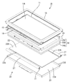
- FIG. 1 is an exploded perspective view showing a schematic configuration of a television receiver according to Embodiment 1.
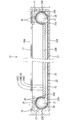
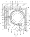
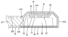
- FIG. Exploded perspective view showing schematic configuration of liquid crystal display device Sectional drawing which shows the cross-sectional structure along the short side direction of a liquid crystal display device Partially enlarged sectional view of a liquid crystal display device showing an arrangement configuration of photorefractive members
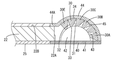
- the partially expanded sectional view which shows the arrangement configuration of the photorefractive member concerning Embodiment 2.
- the partially expanded sectional view which shows the arrangement configuration of the photorefractive member concerning Embodiment 3
- the partially expanded sectional view which shows the arrangement configuration of the photorefractive member concerning Embodiment 4
- the television receiver TV including the liquid crystal display device (display device) 10 is illustrated.
- the television receiver TV includes a liquid crystal display device 10, cabinets Ca and Cb that accommodate the liquid crystal display device 10 sandwiched from the front and back, a power source P, a tuner T for receiving television broadcasts, and the like. And a stand S.
- the liquid crystal display device 10 is accommodated in the cabinets Ca and Cb in a vertically placed posture with the display surface 11A directed in a substantially vertical direction.
- the lower left side (front side of the television receiver TV, the display surface 11A side) in FIG. 1 will be described as the front side, the upper right side as the back side, the upper side as the upper side, and the lower side as the lower side.
- the liquid crystal display device 10 has a horizontally long rectangular shape as a whole, and is a liquid crystal panel (display panel) 11 capable of displaying an image and an external light source that emits light toward the liquid crystal panel 11 as shown in FIG. It has a backlight device 20 (illumination device), and these are integrally held by a bezel 16 or the like.
- the liquid crystal panel 11 includes a pair of transparent (translucent) glass substrates having a horizontally long rectangular shape, and a liquid crystal layer that is interposed between both substrates and whose optical characteristics change with voltage application. Have.
- One of the two substrates is provided with a switching element (for example, TFT) connected to a source wiring and a gate wiring orthogonal to each other, a pixel electrode connected to the switching element, and the like on the other substrate.
- a switching element for example, TFT
- a pixel electrode connected to the switching element, and the like on the other substrate.
- a counter electrode and a color filter in which colored portions such as R, G, and B are arranged in a predetermined arrangement.
- the peripheral edge of the liquid crystal panel 11 is held between the bezel 16 and a frame 24 described later.
- a driver substrate 14 that controls driving of the liquid crystal panel 11 is disposed around the liquid crystal panel 11, and the driver substrate 14 and the liquid crystal panel 11 are connected via a plurality of flexible substrates 15.
- a cold cathode tube (light source) 21 is arranged at the end of the display panel, and the linear light of the cold cathode tube 21 is changed to a planar light by the light guide plate 22, on the liquid crystal panel 11 side. It is a so-called edge light system (side light system) that emits light.
- the backlight device 20 includes a substantially box-shaped chassis 23 opened on the front side (light emission side, liquid crystal panel 11 side), and a frame 24 arranged along the periphery of the chassis 23.
- the light guide plate 22 disposed to face the liquid crystal panel 11 and the cold cathode tube 21 disposed to face the side surface (referred to as the light incident surface 22A) of the light guide plate 22 are accommodated.
- the chassis 23 is made of, for example, a metal such as an aluminum material, and includes a bottom plate 23A having a rectangular shape in plan view, and a side plate 23B that rises from the periphery of the bottom plate 23A to the front side, and the frame 24 is made of metal like the chassis 23. And has a frame shape along the periphery of the chassis 23.
- the light guide plate 22 is made of a resin having high translucency (high transparency) such as acrylic, and is formed in a plate shape having a constant thickness dimension throughout the light guide plate 22.
- the light guide plate 22 has a substantially rectangular shape in plan view.
- light incident from the light incident surface 22 ⁇ / b> A repeats surface reflection and spreads in the light guide plate 22, and is emitted from the main plate surface (referred to as a light emitting surface 22 ⁇ / b> B) as planar light.
- the light guide plate 22 is disposed in the chassis 23 with the light emitting surface 22B facing the front side and the back surface along the bottom plate 23A of the chassis 23.
- the light exit surface 22B and the light incident surface 22A of the light guide plate 22 are substantially perpendicular.
- a reflection sheet 25 that reflects the light emitted from the light guide plate 22 into the light guide plate 22 again is disposed (see FIG. 3).
- the reflection sheet 25 is made of synthetic resin (for example, made of foamed PET), and the surface thereof is white with excellent light reflectivity.
- the reflection sheet 25 is laid over substantially the entire area of the light guide plate 22 between the light guide plate 22 and the bottom plate 23 ⁇ / b> A of the chassis 23.
- an optical member 26 that uses light transmitted through the light guide plate 22 as planar light is disposed on the light exit surface 22B of the light guide plate 22.
- the optical member 26 is formed by laminating a diffusion sheet 26A, a lens sheet 26B, and a reflective polarizing plate 26C in this order from the light guide plate 22 side.
- the cold cathode tube 21 is disposed along a long edge portion (upper edge portion and lower edge portion) extending in the longitudinal direction of the peripheral edge portion of the chassis 23, and the longitudinal dimension of the light guide plate 22. Have the same length. As shown in FIG. 3, the cold cathode tube 21 is disposed between the side plate 23 ⁇ / b> B of the chassis 23 and the light guide plate 22, and is located slightly away from the light incident surface 22 ⁇ / b> A of the light guide plate 22.
- the cold cathode tube 21 is held by holding portions (not shown) made of silicon rubber or the like attached to both ends of the cold cathode tube 21 in contact with an inner peripheral surface of a reflector 27 described later and a light incident surface 22A of the light guide plate 22. Has been.
- the diameter of the cold cathode tube 21 is larger than the thickness of the light guide plate 22 that has been reduced in thickness.
- the outer diameter of the cold cathode tube 21 is ⁇ 2.4 to 4 mm.
- the thickness dimension of the light guide plate 22 is 1 mm.
- Most of the cold cathode tubes 21 are arranged so as to protrude from the light exit surface 22B of the light guide plate 22 to the front side.
- a reflector 27 (reflecting member) is attached along the long edge portion having the light incident surface 22A in the peripheral edge portion of the light guide plate 22.
- the reflector 27 is made of synthetic resin, and its surface is white with excellent light reflectivity.
- the reflector 27 is fitted to the long edge portion of the light guide plate 22 so as to surround substantially the entire circumference of the cold cathode tube 21, and the light incident surface 22 A of the light guide plate 22 is unified from the outer peripheral surface (light emitting surface 21 A) of the cold cathode tube 21. It covers the continuation.
- the inner peripheral surface of the reflector 27 is a reflecting surface 28 that efficiently reflects the light from the cold cathode tube 21 and enters the light incident surface 22 ⁇ / b> A of the light guide plate 22. Note that a white reflection sheet, a specular reflection sheet, or the like may be provided on the inner peripheral surface of the reflector 27.
- the reflector 27 has a length dimension equivalent to the long edges of the cold cathode tube 21 and the light guide plate 22, and has a substantially circular cylindrical shape that is slightly larger than the cold cathode tube 21. A part of the reflector 27 is opened, and a side edge portion of the opening is a fitting portion 27 ⁇ / b> A that fits into a long edge portion of the light guide plate 22. The fitting portion 27A sandwiches the long edge portion of the light guide plate 22 from the front surface side and the back surface side.
- the thickness dimension of the reflector 27 is substantially constant throughout, and is a dimension equivalent to the thickness dimension of the reflection sheet 25.
- a light refraction member 30 that refracts light from the cold cathode tube 21 in a predetermined direction is provided at a position close to the light emitting surface 21A of the cold cathode tube 21.
- the photorefractive member 30 is made of a transparent synthetic resin material, glass, or the like, and is formed in an elongated column shape as a whole.
- the photorefractive member 30 has a length dimension equivalent to the entire length of the cold cathode tube 21.
- the photorefractive member 30 is surrounded by four boundary surfaces. Specifically, a first boundary surface (inclined surface) 31 inclined obliquely with respect to the light emitting surface 21A, and a first boundary A second boundary surface 32 disposed at a position facing the surface 31 and substantially perpendicular to the light emitting surface 21A, and an end of the first boundary surface 31 (an end on the cold cathode tube 21 side) to the second boundary surface 32.
- a third boundary surface 33 extending from one end (end on the cold cathode tube 21 side) and the other end (cold cathode) from the other end (end opposite to the cold cathode tube 21) of the first boundary surface 31 to the other end (cold cathode).
- a fourth boundary surface 34 extending over the end opposite to the tube 21.
- the area of the third boundary surface 33 is much smaller than that of the fourth boundary surface 34, and the photorefractive member 30 has a substantially wedge shape.
- the inclination angle of the first boundary surface 31 with respect to the light emitting surface 21A is such that light emitted from the light emitting surface 21A and incident on the first boundary surface 31 is substantially parallel to the light emitting surface 21A of the cold cathode tube 21 (second boundary). The angle is set so that the light can be refracted on the surface 32 side.
- a plurality of photorefractive members 30 are arranged between the cold cathode tubes 21 and the reflectors 27.
- the plurality of light refracting members 30 are arranged along the light emitting surface 21A of the cold cathode tube 21 in a portion of the light emitting surface 21A excluding a portion facing the light incident surface 22A of the light guide plate 22.
- the photorefractive member 30 is disposed from the position close to the front side of the light incident surface 22A of the light guide plate 22 in the light emitting surface 21A to the position directly behind the cold cathode tube 21 in FIG.
- the clockwise direction in FIG. 4 is referred to as a clockwise direction
- the counterclockwise direction is referred to as a counterclockwise direction.
- Each light refracting member 30 has the first boundary surface 31 facing backward in the clockwise direction, the second boundary surface 32 facing forward in the clockwise direction, and the light refracted at the first boundary surface 31 traveling in the clockwise direction. Has been placed. All the light refracting members 30 have the same direction, and the peripheral edges of the fourth boundary surface 34 are abutted with each other and are arranged without a gap. Each photorefractive member 30 is positioned by bringing the third boundary surface 33 into contact with the light emitting surface 21A of the cold cathode tube 21 and bringing the fourth boundary surface 34 into contact with the reflection surface 28 of the reflector 27.
- the refraction member 30 is referred to as a first light refraction member 30A, and the nth light refraction member 30 arranged in the clockwise direction therefrom is the nth light refraction member 30B, and the n + 1th light refraction member.
- the light refracting member 30 is arranged such that light incident on the first boundary surface 31 of the nth light refracting member 30B among the plurality of light refracting members 30 is refracted at the first boundary surface 31 and the second boundary surface. 32 is emitted in the clockwise direction, enters the first boundary surface 31 of the (n + 1) th light refracting member 30C, passes through the (n + 1) th light refracting member 30C, and eventually reaches the first of the n + xth light refracting member 30E.
- the light is incident on one boundary surface 31, passes through the light refraction member 30 ⁇ / b> E, and is emitted toward the light incident surface 22 ⁇ / b> A of the light guide plate 22.
- the light emitted toward the light incident surface 22 ⁇ / b> A of the light guide plate 22 enters the light incident surface 22 ⁇ / b> A of the light guide plate 22 directly or after being reflected by the reflecting surface 28.
- the second boundary surface 32 of the (n + x) th light refracting member 30E faces the light incident surface 22A of the light guide plate 22 in substantially parallel.
- the backlight device 20 of the present embodiment includes a light guide plate 22 disposed to face the liquid crystal panel 11 and a cold cathode tube 21 disposed to face the light incident surface 22A of the light guide plate 22.
- the backlight device 20 emits light from the cathode tube 21 to the liquid crystal panel 11 by changing the light from the light guide plate 22 to planar light, and is located near the light emitting surface 21A of the cold cathode tube 21 at the light emitting surface 21A.
- a light refraction member 30 is provided which refracts light of the cold cathode tube 21 incident on the first boundary surface 31 in a predetermined direction. 30 is arranged such that the light refracted at the first boundary surface 31 is directed toward the light incident surface 22A of the light guide plate 22.
- the light from the cold cathode tube 21 enters the first boundary surface 31 of the light refraction member 30 and is refracted, passes through the light refraction member 30, and travels toward the light incident surface 22A of the light guide plate 22. Even if the light incident surface 22A of 22 is not enlarged, the loss of light from the cold cathode fluorescent lamp 21 can be reduced.
- the reflecting surface 28 which covers the outer peripheral surface (surface opposite to the light emitting surface 21A) of the photorefractive member 30 and the light incident surface 22A of the light guide plate 22 is provided, the light of the cold cathode tube 21 is provided. Is refracted by the light refracting member 30 and is reflected by the reflecting surface 28 while being reflected toward the light incident surface 22A, so that the loss of light from the cold cathode tube 21 can be reduced.
- the light refracting member 30 has a length dimension equivalent to the dimension in the extending direction of the cold cathode tube 21, for example, a plurality of light refracting members are arranged coaxially in the extending direction of the cold cathode tube 21. Compared with the arrangement, a simple structure can be obtained, and more light can be refracted in a predetermined direction because the light refraction member 30 is not cut.
- the backlight device 20 of the present embodiment is different from the first embodiment in that the light source is an LED substrate 40 in which LEDs (point light sources) 42 are arranged on a substrate 41 having a longitudinal shape.
- symbol is attached
- the backlight device 20 includes a chassis 23 and a frame 24.
- a light guide plate 22 is accommodated in the chassis 23, and faces the light incident surface 22 ⁇ / b> A of the light guide plate 22.
- the LED substrate 40 is provided.
- the substrate 41 of the LED substrate 40 is a substrate in which a wiring pattern made of a metal film such as copper foil is formed on a base material made of an insulating material such as synthetic resin (glass epoxy resin) or ceramics, or an aluminum-based material or the like. A wiring pattern is formed on a base material made of a metal material through an insulating layer. A white resist (not shown) that easily reflects the light of the LED 42 is applied to the surface of the substrate 41.
- the substrate 41 has a length dimension equivalent to the long side of the light guide plate 22.
- the LEDs 42 are mounted in a line (linearly) in the longitudinal direction of the substrate 41.
- the LED 42 is molded by a transparent resin material into a semicircular shape in which the light emitting surface 43 (surface opposite to the mounting surface with respect to the substrate 41) forms a curved surface.
- the LED board 40 is fixed to the bottom plate 23A of the chassis 23 with screws (not shown) or the like.
- the LED substrate 40 is arranged in such a posture that the plate surface of the substrate 41 is substantially parallel to the plate surface of the light guide plate 22 and the light emitting surface 43 faces the front side.
- the side edges of the substrate 41 and the reflection sheet 25 are in contact with each other and are disposed flush with each other.
- the side edge portion of the substrate 41 is located on the back side of the light incident surface 22 ⁇ / b> A of the light guide plate 22. It is in contact with the back side.
- a reflector 44 is attached to the long edge portion having the light incident surface 22A in the peripheral edge portion of the light guide plate 22 as in the first embodiment.
- the reflector 44 is made of synthetic resin, and the surface thereof is white with excellent light reflectivity.
- the inner peripheral surface of the reflector 44 efficiently reflects the light from the LED 42, and the light guide plate
- the reflecting surface 45 is made incident on the 22 light incident surface 22A.
- the reflector 44 has a substantially semicircular cross-sectional shape covering substantially the entire light emitting surface 43 and is fitted to the long edge portion of the light guide plate 22 so that the light incident surface 22A of the light guide plate 22 extends from the light emitting surface 43 of the LED 42. Covered in a row.
- the reflector 44 has a length dimension equivalent to that of the LED substrate 40, and one long edge of the pair of long edges contacts the long edge of the LED substrate 40 (substrate 41) and is fixed to the substrate 41. Is in contact with the front side of the light incident surface 22 ⁇ / b> A of the light guide plate 22.
- the portion of the reflector 44 that contacts the front side of the light incident surface 22A of the light guide plate 22 is a fitting portion 44A that sandwiches the long edge portion of the light guide plate 22 with the substrate 41 of the LED substrate 40. Yes.
- the light-refractive member 30 which refracts the light of LED42 to a predetermined direction is provided in the position close
- Each light-refractive member 30 is the same as that of Embodiment 1. And has a length dimension equivalent to the total length of the LED substrate 40.
- a plurality of the light refraction members 30 are arranged side by side between the LED substrate 40 and the reflector 44, and the plurality of light refraction members 30 are arranged along the light emission surface 43 of the LED 42. 43 is disposed in a portion excluding a portion facing the light incident surface 22 ⁇ / b> A of the light guide plate 22.
- Each light refracting member 30 has the first boundary surface 31 facing away from the light guide plate 22, the second boundary surface 32 facing toward the side closer to the light guide plate 22, and light refracted at the first boundary surface 31. It arrange
- the light refracting member 30 disposed at the position farthest from the light incident surface 22A of the light guide plate 22 among the plurality of light refracting members 30 is the first light refracting member 30A.
- the n-th photorefractive member 30 arranged on the light guide plate 22 side (left side in FIG. 5) is designated as the nth photorefractive member 30B
- the (n + 1) -th photorefractive member 30 is designated as the (n + 1) th.
- the light refracting member 30C and the light refracting member 30 disposed at a position closest to the light incident surface 22A of the light guide plate 22 will be referred to as an (n + x) th light refracting member 30E.
- the light refracting member 30 is arranged such that light incident on the first boundary surface 31 of the nth light refracting member 30B among the plurality of light refracting members 30 is refracted at the first boundary surface 31 and the second boundary surface. 32 is emitted to the light guide plate 22 side (left side in FIG. 5), enters the first boundary surface 31 of the (n + 1) th light refracting member 30C, passes through the (n + 1) th light refracting member 30C, and eventually reaches the (n + x) th.
- the light refracting member 30 ⁇ / b> E is incident on the first boundary surface 31, passes through the (n + x) th light refracting member 30 ⁇ / b> E, and is emitted toward the light incident surface 22 ⁇ / b> A of the light guide plate 22.
- the first light refracting member 30A is disposed at a position closest to the back side where the periphery of the fourth boundary surface 34 is in contact with the substrate 41.
- the n + xth light refracting member 30E is the light emitting surface of the LED 42. It is arranged at a position closer to the light guide plate 22 side than the face number 43.
- the LED 42 has the first boundary surface 31 inclined obliquely with respect to the light emitting surface 43 at a position close to the light emitting surface 43, and is incident on the first boundary surface 31.
- a light refracting member 30 that refracts light from the LED 42 in a predetermined direction is provided, and the light refracting member 30 is disposed so that light refracted at the first boundary surface 31 is directed toward the light incident surface 22A of the light guide plate 22. Therefore, as in the first embodiment, the light from the LED 42 enters the first boundary surface 31 of the light refracting member 30 and is refracted, passes through the light refracting member 30, and travels toward the light incident surface 22A of the light guide plate 22. Therefore, the loss of light from the cold cathode fluorescent lamp 21 can be reduced without increasing the light incident surface 22A of the light guide plate 22.
- a backlight device 20 according to Embodiment 3 embodying the present invention will be described with reference to FIG.
- the backlight device 20 of the present embodiment is different from the second embodiment in that the LED substrate 40 is arranged in a direction in which the plate surface of the substrate 41 is substantially perpendicular to the plate surface of the light guide plate 22.
- symbol is attached
- the backlight device 20 includes a chassis 23 and a frame 24.
- a light guide plate 22 is accommodated in the chassis 23, and faces the light incident surface 22 ⁇ / b> A of the light guide plate 22.
- the LED substrate 40 is provided.
- the LED substrate 40 is obtained by arranging LEDs 42 (point light sources) on a substrate 41 having a longitudinal shape.
- the LED board 40 is disposed in such a manner that its plate surface is substantially perpendicular to the plate surface of the light guide plate 22 and the light emitting surface 43 faces the light guide plate 22 side (inside), and is attached to the side plate 23B of the chassis 23 with screws (not shown). It is fixed by.
- the pair of LED substrates 40 are in a state where the light emitting surfaces 43 of the LEDs 42 face each other with the light guide plate 22 interposed therebetween.
- the reflector 50 is attached to the long edge part which has 22 A of light-incidence surfaces among the peripheral parts of the light-guide plate 22 similarly to Embodiment 2.
- FIG. The reflector 50 is made of a synthetic resin as in the second embodiment, and the surface thereof is white with excellent light reflectivity, and the inner peripheral surface efficiently reflects the light from the LED 42, and the light guide plate 22.
- the reflection surface 53 is made incident on the light incident surface 22A.
- the reflector 50 includes a first reflector 51 that covers the light emitting surface 43 of the LED 42 from the front side, and a second reflector 52 that covers the light emitting surface 43 of the LED 42 from the back side, and covers substantially the entire light emitting surface 43 side of the LED substrate 40.
- the light guide plate 22 is fitted to the long edge of the light guide plate 22 and covers the light incident surface 22A of the light guide plate 22 from the light emitting surface 43 of the LED 42 in a row.
- the reflector 50 has a length dimension equivalent to that of the LED substrate 40 as in the second embodiment.
- the first reflector 51 has a substantially arc-shaped cross section that covers a portion of the light emitting surface 43 of the LED 42 that protrudes to the front side from the light incident surface 22A of the light guide plate 22.
- One long edge of the first reflector 51 is fixed in contact with the long edge of the LED substrate 40, and the other long edge is in contact with the front side of the light incident surface 22 ⁇ / b> A of the light guide plate 22.
- the second reflector 52 is arranged between the side edge of the reflection sheet 25 and the long edge of the LED substrate 40, and has a long and narrow plate shape that covers the light emitting surface 43 of the LED 42 from the back side. Side edges of the second reflector 52 and the reflection sheet 25 are in contact with each other and are disposed flush with each other. The side edge portion of the second reflector 52 on the side in contact with the reflection sheet 25 is located on the back side of the light incident surface 22 ⁇ / b> A of the light guide plate 22 and is in contact with the back surface of the light guide plate 22.
- One long edge portion of the first reflector 51 and one long edge portion of the second reflector 52 constitute a fitting portion 50 ⁇ / b> A that sandwiches and fits the long edge portion of the light guide plate 22 from the front and back.
- each light-refractive member 30 which refracts the light of LED42 to a predetermined direction is provided in the position close
- Each light-refractive member 30 is the same as that of Embodiment2. It has the composition of.
- a plurality of the light refraction members 30 are arranged side by side between the LED 42 and the reflector 50, and the plurality of light refraction members 30 are arranged on the light emission surface 43 along the light emission surface 43 of the LED 42. It arrange
- each light refraction member 30 has the first boundary surface 31 facing away from the light guide plate 22, the second boundary surface 32 facing toward the light guide plate 22, and the third boundary surface 33 facing the LED 42.
- the fourth boundary surface 34 is disposed on the light emitting surface 43 in contact with the reflecting surface 53 of the reflector 50.
- the light refracting member 30 disposed at the position farthest from the light incident surface 22A of the light guide plate 22 among the plurality of light refracting members 30 is the first light refracting member 30A.
- the nth light refracting member 30 disposed on the light guide plate 22 side (the lower side in FIG. 6) is referred to as the nth light refracting member 30B, and the (n + 1) th light refracting member 30 is defined as the (n + 1) th from there.
- the light refraction member 30 arranged at the position closest to the light incident surface 22A of the light guide plate 22 will be referred to as the (n + x) th light refraction member 30E.
- the light is transmitted, eventually enters the first boundary surface 31 of the (n + x) th light refracting member 30E, passes through the (n + x) th light refracting member 30E, and is emitted toward the light incident surface 22A of the light guide plate 22. is there.
- the first light refracting member 30A is arranged at a position closest to the front surface side of the light emitting surface 43 where the periphery of the fourth boundary surface 34 is in contact with the substrate 41, and the (n + x) th light refracting member 30E is
- the peripheral edge of the fourth boundary surface 34 is arranged at a position where it contacts the front edge of the light incident surface 22 ⁇ / b> A of the light guide plate 22.
- the light refraction member 30 that refracts the light of the LED 42 incident on the first boundary surface 31 in a predetermined direction is disposed at a position close to the light emitting surface 43 of the LED 42.
- the effect of reducing the loss of light from the cold cathode tube 21 can be obtained without increasing the light incident surface 22A of the light guide plate 22.
- a backlight device 20 according to a fourth embodiment embodying the present invention will be described with reference to FIG.
- the backlight device 20 of the present embodiment is different from that of the second embodiment in that the LED 60 has a rectangular parallelepiped shape in which the light emitting surface 63 forms a flat surface.
- symbol is attached
- the backlight device 20 includes a chassis 23 and a frame 24.
- a light guide plate 22 is accommodated in the chassis 23, and faces the light incident surface 22 ⁇ / b> A of the light guide plate 22.
- the LED substrate 40 is provided.
- the LED substrate 40 is configured by arranging LEDs (point light sources) 60 on a substrate 41 having a longitudinal shape, and the LEDs 60 are arranged in a line (linearly) in the longitudinal direction of the substrate 41.
- the LED 60 is molded into a rectangular parallelepiped shape with a light emitting surface 63 (a surface opposite to the mounting surface with respect to the substrate 41) formed of a transparent resin material.
- the LED substrate 40 is arranged in such a manner that the plate surface thereof is substantially parallel to the plate surface of the light guide plate 22 and the light emitting surface 63 faces the front side, and the substrate 41 of the LED substrate 40 and the reflection sheet 25 are arranged.
- the side edges of the substrate 41 are located on the back side of the light incident surface 22 ⁇ / b> A of the light guide plate 22 and are in contact with the back surface of the light guide plate 22.
- the side surface of the LED 60 and the light incident surface 22A of the light guide plate 22 face each other substantially in parallel, and the light emitting surface 63 of the LED 60 and the light emitting surface 22B of the light guide plate 22 are positioned at substantially the same height. .
- a reflector 61 is attached to the long edge portion having the light incident surface 22A in the peripheral edge portion of the light guide plate 22 as in the second embodiment.
- the reflector 61 is made of a synthetic resin as in the second embodiment, and the surface thereof is white with excellent light reflectivity, and the inner peripheral surface efficiently reflects the light from the LED 60, and the light guide plate 22.
- the reflection surface 62 is made incident on the light incident surface 22A.
- the reflector 61 forms a shallow lid that covers substantially the entire light emitting surface 63 of the LED 60 and is fitted to the long edge portion of the light guide plate 22, and continues from the light emitting surface 63 of the LED 60 to the light incident surface 22 ⁇ / b> A of the light guide plate 22. Covering.
- the reflector 61 includes a facing portion 61 ⁇ / b> A that faces the light emitting surface 63 of the LED 60, a standing portion 61 ⁇ / b> B that stands on the opposite side of the light guide plate 22 of the LED 60, and a fitting portion that fits the long edge portion of the light guide plate 22. 61C.
- the facing portion 61 ⁇ / b> A of the reflector 61 is substantially parallel to the light emitting surface 63 of the LED 60, and the standing portion 61 ⁇ / b> B is substantially parallel to the side surface of the LED 60.
- the fitting portion 61 ⁇ / b> C is in contact with the light emitting surface 22 ⁇ / b> B of the light guide plate 22 and sandwiches the long edge portion of the light guide plate 22 between the LED substrate 40 and the substrate 41.
- the back side end of the upright portion 61 ⁇ / b> B of the reflector 61 is in contact with and fixed to the long edge of the LED substrate 40.
- the far corner is inclined with respect to the light emitting surface 63 of the LED 60 (inclination in the direction of approaching the substrate 41 from the facing portion 61A toward the standing portion 61B or the fitting portion 61C).
- the reflector 61 has the same length as the long edges of the LED substrate 40 and the light guide plate 22 as in the second embodiment.
- a light refraction member 30 that refracts the light of the LED 60 in a predetermined direction is provided at a position close to the light emitting surface 63 of the LED 60 as in the second embodiment.
- the photorefractive member 30 has the same configuration as that of the second embodiment and has a length dimension equivalent to the entire length of the LED substrate 40. Note that the photorefractive member 30 of the present embodiment has areas of the third boundary surface 33 and the fourth boundary surface 34 with respect to the first boundary surface 31 and the second boundary surface 32 as compared to the photorefractive member 30 of the second embodiment. It has a large shape.
- each light refraction member 30 has the first boundary surface 31 facing away from the light guide plate 22, the second boundary surface 32 facing toward the light guide plate 22, and the third boundary surface 33 facing the LED 60.
- the fourth boundary surface 34 is in contact with the reflecting surface 62 of the reflector 61 and is disposed on the light emitting surface 63 without any gap.
- the arrangement of the light refracting members 30 is, for example, that light incident on the first boundary surface 31 of the light refracting member 30 disposed at the center of the three light refracting members 30 is light guide plate 22 on the first boundary surface 31.
- the light is refracted to the side and is emitted from the second boundary surface 32 to the light guide plate 22 side (left side in FIG. 7), and is incident on the first boundary surface 31 of the light refracting member 30 disposed adjacent thereto. Is transmitted toward the light incident surface 22 ⁇ / b> A of the light guide plate 22.
- the light refraction member 30 that refracts the light of the LED 60 incident on the first boundary surface 31 in a predetermined direction is disposed at a position close to the light emitting surface 63 of the LED 60.
- the effect of reducing the loss of light from the cold cathode tube 21 can be obtained without increasing the light incident surface 22A of the light guide plate 22.
- a backlight device 20 according to a fifth embodiment embodying the present invention will be described with reference to FIG.
- the backlight device 20 of the present embodiment is different from the fourth embodiment in that the LED substrate 40 is arranged in a direction in which the plate surface of the substrate 41 is substantially perpendicular to the plate surface of the light guide plate 22.
- symbol is attached
- the backlight device 20 of the present embodiment includes a chassis 23 and a frame 24.
- a light guide plate 22 is accommodated in the chassis 23, and faces the light incident surface 22A of the light guide plate 22.
- the LED substrate 40 is provided.
- the LED substrate 40 is obtained by arranging LEDs (point light sources) 60 on a substrate 41 having a longitudinal shape.
- the LED board 40 is disposed in such a manner that its plate surface is substantially perpendicular to the plate surface of the light guide plate 22 and the light emitting surface 63 faces the light guide plate 22 side (inner side). It is fixed by.
- the pair of LED substrates 40 are in a state where the light emitting surfaces 63 of the LEDs 60 face each other with the light guide plate 22 interposed therebetween. Most of the light emitting surface 63 of the LED 60 protrudes more to the front side than the light emitting surface 22B of the light guide plate 22.
- a reflector 70 is attached to the long edge portion having the light incident surface 22A in the peripheral edge portion of the light guide plate 22 as in the fourth embodiment.
- the reflector 70 is made of synthetic resin as in the fourth embodiment, and the surface thereof is white with excellent light reflectivity.
- the inner peripheral surface efficiently reflects the light from the LED 60, and the light guide plate 22.
- the reflecting surface 73 is made incident on the light incident surface 22A.
- the reflector 70 includes a first reflector 71 that covers the light emitting surface 63 of the LED 60 from the front side, and a second reflector 72 that covers the light emitting surface 63 of the LED 60 from the back side.
- the light guide plate 22 covers substantially the entire light emitting surface 63 side.
- the light-incident surface 22A of the light guide plate 22 is continuously covered from the light-emitting surface 63 of the LED 60.
- the first reflector 71 covers a portion of the light emitting surface 63 of the LED 60 that protrudes more to the front side than the light incident surface 22A of the light guide plate 22.
- the first reflector 71 has a facing portion 70A that faces the light emitting surface 63 of the LED 60 and a standing portion 70B that stands on the opposite side of the second reflector 72, and as a whole, a light emitting surface of the light guide plate 22 It has a shape that rises to the front side from 22B.
- the facing portion 70 ⁇ / b> A of the first reflector 71 is substantially parallel to the light emitting surface 63 of the LED 60
- the standing portion 70 ⁇ / b> B is substantially parallel to the side surface of the LED 60.
- the end portion of the upright portion 70 ⁇ / b> B of the reflector 70 is fixed in contact with the long edge of the LED substrate 40.
- the connecting portion between the facing portion 70A and the upright portion 70B and the connecting portion between the facing portion 70A and the fitting portion 70C, in other words, the front-side corner portion and the back-side corner portion of the first reflector 71 are the light emitting surface of the LED 60. It is inclined with respect to 63 (inclination in a direction approaching the second reflector 72 from the substrate 41 side toward the light guide plate 22 side).
- the second reflector 72 is disposed between the side edge of the reflection sheet 25 and the long edge of the LED substrate 40, and has a long and narrow plate shape that covers the light emitting surface 63 of the LED 60 from the back side.
- the second reflector 72 and the reflection sheet 25 are arranged such that the side edges are in contact with each other and are flush with each other.
- the side edge of the second reflector 72 on the reflection sheet 25 side is located on the back side of the light incident surface 22 ⁇ / b> A of the light guide plate 22 and is in contact with the back surface of the light guide plate 22.
- the back-side end of the first reflector 71 and the side edge of the second reflector 72 on the reflection sheet 25 side constitute a fitting portion 70 ⁇ / b> C that fits with the long edge of the light guide plate 22 sandwiched from the front and back. Yes. Further, the edge of the second reflector 72 opposite to the fitting portion 70 ⁇ / b> C is in contact with and fixed to the long edge of the LED substrate 40.
- the reflector 70 has the same length as the long edges of the LED substrate 40 and the light guide plate 22 as in the fourth embodiment.
- a light refraction member 30 that refracts the light of the LED 60 in a predetermined direction is provided at a position close to the light emitting surface 63 of the LED 60, and each light refraction member 30 is the same as that of the fourth embodiment.
- a plurality (two in this embodiment) are arranged side by side between the LED 60 and the reflector 70.
- the plurality of light refracting members 30 are arranged side by side along the light emitting surface 63 of the LED 60 on the front side of the light emitting surface 63 relative to the portion facing the light incident surface 22 ⁇ / b> A of the light guide plate 22.
- Each light refracting member 30 is refracted at the first boundary surface 31 with the first boundary surface 31 facing away from the light guide plate 22 and the second boundary surface 32 facing toward the light guide plate 22 as in the fourth embodiment.
- the light is arranged in a direction to proceed to the light guide plate 22 side (lower side in FIG. 8). Both the light refraction members 30 are set in the same direction, and the peripheral edges of the fourth boundary surface 34 are abutted with each other, and are arranged without a gap.
- Each light refraction member 30 is positioned by bringing the third boundary surface 33 into contact with the light emitting surface 63 of the LED 60 and the fourth boundary surface 34 into contact with the reflecting surface 73 of the reflector 70, as in the fourth embodiment.
- the fourth boundary surface 34 of both the light refraction members 30 is in contact with the substantially entire surface of the facing portion 70 ⁇ / b> A of the first reflector 71.
- the arrangement of the light refracting member 30 is such that, for example, light incident on the first boundary surface 31 of the light refracting member 30 disposed on the far side of the light refracting member 30 in the light refracting member 30 is incident on the light guide plate at the first boundary surface 31.
- This light is refracted on the 22 side (the lower side in FIG. 7) and emitted from the second boundary surface 32 to the light guide plate 22 side, and enters the first boundary surface 31 of the light refraction member 30 on the side close to the light guide plate 22.
- the light passes through the refractive member 30 and is emitted toward the light incident surface 22 ⁇ / b> A of the light guide plate 22.
- the light refraction member 30 that refracts the light of the LED 60 incident on the first boundary surface 31 in a predetermined direction is disposed at a position close to the light emitting surface 63 of the LED 60.
- the effect of reducing the loss of light from the cold cathode tube 21 can be obtained without increasing the light incident surface 22A of the light guide plate 22.
- the photorefractive member 30 is configured to be surrounded by four boundary surfaces.
- the present invention is not limited to this, and the first boundary surface 31 is inclined obliquely with respect to the light emitting surface 21A. Any structure may be used as long as it has an (inclined surface).
- the structure may be surrounded by three boundary surfaces excluding the third boundary surface 33, and may be surrounded by five or more boundary surfaces. It is good also as a structure formed.
- the plurality of light refraction members 30 are all in the same direction, but are not limited thereto, and may be arranged in different directions.
- the photorefractive member 30 is arranged around the cold cathode tube 21 as in the first embodiment, the photorefractive member is arranged in a substantially half region on the side close to the light guide plate 22 in the light emitting surface 21A. 30 may be in the opposite direction to that of the first embodiment (the direction in which light refracted at the first boundary surface 31 travels counterclockwise).
- the photorefractive member 30 brings the third boundary surface 33 into contact with the light emitting surfaces 21A, 43, 63 of the light sources 21, 42, 60, and the fourth boundary surface 34 with the reflectors 27, 44, 50. , 61 and 70 are positioned by bringing them into contact with the reflecting surfaces 28, 45, 53, 62 and 73, but the present invention is not limited to this, and the photorefractive member is applied to the reflector by a transparent adhesive or adhesive tape. It may be fixed. At this time, the photorefractive member may be arranged at a position away from the light source.
- the reflectors 27, 44, 50, 61, 70 are made of synthetic resin.
- the present invention is not limited to this, and the reflector may be formed of, for example, a highly reflective metal plate.
- the photorefractive member 30 has a length dimension equivalent to the total length of the light source, but is not limited thereto, and may be shorter than the light source.
- the length direction of the light source A plurality of the light sources may be arranged without gaps, and when the light source is an LED substrate, it may be arranged in accordance with the LED arrangement position.
- the separate light refracting members 30 are arranged side by side.
- the present invention is not limited to this, and a plurality of light refracting members are integrally formed, for example, along the inner peripheral surface of the reflector. You may arrange
- TV ... TV receiver 10 ... Liquid crystal display device (display device), 11 ... Liquid crystal panel (display panel), 20 ... Backlight device (illumination device), 21 ... Cold cathode tube (light source), 21A, 43, 63 ... Light emitting surface, 22 ... light guide plate, 22A ... light incident surface (side surface of light guide plate), 28, 45, 53, 62, 73 ... reflecting surface, 30 ... light refraction member, 30B ... nth light refraction member, 30C ... n + 1th photorefractive member, 30E ... n + xth photorefractive member (most photorefractive member), 31 ... first boundary surface (inclined surface), 40 ... LED substrate (light source), 41 ... Substrate, 42, 60 ... LED (point light source)
Landscapes
- Physics & Mathematics (AREA)
- General Physics & Mathematics (AREA)
- Optics & Photonics (AREA)
- Nonlinear Science (AREA)
- Mathematical Physics (AREA)
- Chemical & Material Sciences (AREA)
- Crystallography & Structural Chemistry (AREA)
- Planar Illumination Modules (AREA)
Abstract
導光板の側面を大きくせずとも、光源からの光のロスを小さくすることが可能な照明装置、表示装置およびテレビ受信装置を提供する。表示パネル11に対向して配置される導光板22と、前記導光板22の側面22Aに対向して配置される光源21と、を備え、前記光源21の光を前記導光板22により面状の光に変えて前記表示パネル11側に出射する照明装置20であって、前記光源21の発光面21Aと近接した位置には、前記発光面21Aに対して斜めに傾斜する傾斜面31を有し、この傾斜面31に入射した前記光源21の光を所定の方向に屈折させる光屈折部材30が設けられ、この光屈折部材30は、前記傾斜面31において屈折した光が、前記導光板22の側面に向かうように配置されている。
Description
本発明は、照明装置、表示装置およびテレビ受信装置に関する。
例えば液晶テレビの表示装置等、自発光しない表示パネルを用いるものには、一般に、表示装置用の照明装置が備えられている。この種の照明装置として、表示パネルの端に光源を配置し、この光源の光を導光板により面状の光に変えて表示パネル側に出射させる、いわゆるエッジライト方式のものが知られている。
ところで、近年においては、表示装置の薄型化が顕著であり、それに伴って導光板の薄型化も進んでいる。しかし、導光板の薄型化が進むにつれ、導光板の側面(光源と対向する部分)が、光源の発光面に比べて小さくなり、光源の光の一部分が導光板に入射されないというロスが生じるようになった。そこで、このようなロスを小さくするために、導光板の側面のみを大きくする方法、すなわち導光板の略全体を薄くし、光源と対向する側縁部のみを厚くする方法が知られている(例えば、特許文献1)。
(発明が解決しようとする課題)
しかし、上記のように、厚さ寸法が一定でない導光板を、射出成型により製造しようとすると、金型のキャビティ内の溶融樹脂材料を冷却固化させる工程において、厚い部分と薄い部分とで体積収縮量に差が生じ、厚い部分でひけが生じる等して、形状精度が悪くなるという問題がある。
しかし、上記のように、厚さ寸法が一定でない導光板を、射出成型により製造しようとすると、金型のキャビティ内の溶融樹脂材料を冷却固化させる工程において、厚い部分と薄い部分とで体積収縮量に差が生じ、厚い部分でひけが生じる等して、形状精度が悪くなるという問題がある。
そして、形状精度を良くするためには、樹脂温度や金型温度、樹脂の充填密度や射出圧力等をバランスよく調整することが必要であるけれども、そのような調整は容易ではなく、コストが高くなるという問題がある。特に、近年のように、表示装置の大型化が顕著である場合には、形状精度を良くすることの困難性が余計に増すため、導光板の側面を大きくせずとも、光源からの光のロスを小さくすることが可能な手段が望まれていた。
本発明は上記のような事情に基づいて完成されたものであって、導光板の側面を大きくせずとも、光源からの光のロスを小さくすることが可能な照明装置、表示装置およびテレビ受信装置を提供することを目的とする。
(課題を解決するための手段)
本発明の照明装置は、表示パネルに対向して配置される導光板と、前記導光板の側面に対向して配置される光源と、を備え、前記光源の光を前記導光板により面状の光に変えて前記表示パネル側に出射する照明装置であって、前記光源の発光面と近接した位置には、前記発光面に対して斜めに傾斜する傾斜面を有し、この傾斜面に入射した前記光源の光を所定の方向に屈折させる光屈折部材が設けられ、この光屈折部材は、前記傾斜面において屈折した光が、前記導光板の側面に向かうように配置されている。
本発明の照明装置は、表示パネルに対向して配置される導光板と、前記導光板の側面に対向して配置される光源と、を備え、前記光源の光を前記導光板により面状の光に変えて前記表示パネル側に出射する照明装置であって、前記光源の発光面と近接した位置には、前記発光面に対して斜めに傾斜する傾斜面を有し、この傾斜面に入射した前記光源の光を所定の方向に屈折させる光屈折部材が設けられ、この光屈折部材は、前記傾斜面において屈折した光が、前記導光板の側面に向かうように配置されている。
このような構成によれば、光源の光は、光屈折部材の傾斜面に入射して屈折し、光屈折部材を透過して導光板の側面に向かうから、導光板の光入射面を大きくせずとも、光源からの光のロスを小さくすることができる。
また、前記光屈折部材は、前記傾斜面における前記光の屈折方向に複数が並んで配置され、第n番目の前記光屈折部材の前記傾斜面に入射した光は、前記光の屈折方向に隣接して配置された第n+1番目の前記光屈折部材に入射し、最も端に配置された前記光屈折部材から前記導光板の側面に向けて出射される構成であるものとしてもよい。
また、前記光屈折部材の前記発光面とは反対側の面および前記導光板の側面を一続きに覆う反射面が備えられているものとしてもよい。このような構成によれば、光源の光は、光屈折部材により屈折し、また反射面に当たって反射しつつ、導光板の側面に向かうから、光源からの光のロスを小さくすることができる。
また、前記光屈折部材は、前記発光面および前記反射面に接触することで位置決めされているものとしてもよい。
また、前記光源は、一方向に延びる線状光源であるものとしてもよい。
また、前記光源は、一方向に延びる線状光源であるものとしてもよい。
また、前記光屈折部材は、前記光源の延び方向の寸法と同等の長さ寸法を有するものとしてもよい。このような構成によれば、例えば、複数の光屈折部材を光源の延び方向に並べて配置する場合に比べて、シンプルな構造とすることができ、また、切れ目がない分より多くの光を所定の方向に屈折させることができる。
また、前記線状光源は、冷陰極管であって、前記光屈折部材は、前記冷陰極管の発光面に沿って周方向に複数が並んで配置され、第n番目の前記光屈折部材の前記傾斜面に入射した光は、前記周方向に隣接して配置された第n+1番目の前記光屈折部材に入射し、最も端に配置された前記光屈折部材から前記導光板の側面に向けて出射される構成であるものとしてもよい。
また、前記線状光源は、長手状をなす基板に点状光源が配列されたものとしてもよい。
また、前記点状光源は、LEDであって、前記光屈折部材は、前記LEDの発光面に沿って前記導光板の側面に接近する方向に複数が並んで配置され、第n番目の前記光屈折部材の前記傾斜面に入射した光は、前記導光板の側面に近い側に隣接して配置された第n+1番目の前記光屈折部材に入射し、最も端に配置された前記光屈折部材から前記導光板の側面に向けて出射される構成であるものとしてもよい。
また、前記点状光源は、LEDであって、前記光屈折部材は、前記LEDの発光面に沿って前記導光板の側面に接近する方向に複数が並んで配置され、第n番目の前記光屈折部材の前記傾斜面に入射した光は、前記導光板の側面に近い側に隣接して配置された第n+1番目の前記光屈折部材に入射し、最も端に配置された前記光屈折部材から前記導光板の側面に向けて出射される構成であるものとしてもよい。
また、前記点状光源は、前記発光面が曲面をなす半円形状のものとしてもよい。
また、前記点状光源は、前記発光面が平面をなす直方体状のものとしてもよい。
また、前記光源は、前記基板の板面が前記導光板の板面と略平行をなす向きで配置されているものとしてもよい。
また、前記光源は、前記基板の板面が前記導光板の板面と略直角をなす向きで配置されているものとしてもよい。
また、前記点状光源は、前記発光面が平面をなす直方体状のものとしてもよい。
また、前記光源は、前記基板の板面が前記導光板の板面と略平行をなす向きで配置されているものとしてもよい。
また、前記光源は、前記基板の板面が前記導光板の板面と略直角をなす向きで配置されているものとしてもよい。
本発明の表示装置は、前記照明装置と、前記照明装置からの光を利用して表示を行う表示パネルと、を備える。
また、前記表示パネルが液晶を用いた液晶パネルであるものとしてもよい。
本発明のテレビ受信装置は、前記表示装置を備える。
また、前記表示パネルが液晶を用いた液晶パネルであるものとしてもよい。
本発明のテレビ受信装置は、前記表示装置を備える。
(発明の効果)
本発明によれば、導光板の側面を大きくせずとも、光源からの光のロスを小さくすることが可能な照明装置、表示装置およびテレビ受信装置を提供することができる。
本発明によれば、導光板の側面を大きくせずとも、光源からの光のロスを小さくすることが可能な照明装置、表示装置およびテレビ受信装置を提供することができる。
<実施形態1>
以下、本発明の実施形態1を図1~図4によって説明する。本実施形態では、液晶表示装置(表示装置)10を備えるテレビ受信装置TVについて例示する。テレビ受信装置TVは、図1に示すように、液晶表示装置10と、液晶表示装置10を表裏から挟むようにして収容するキャビネットCa,Cbと、電源Pと、テレビ放送などを受信するためのチューナーTと、スタンドSとを備えている。液晶表示装置10は、表示面11Aを略鉛直方向に向けた縦置き姿勢でキャビネットCa,Cbに収容されている。以下、各構成部材において、図1の左下側(テレビ受信装置TVの正面側、表示面11A側)を表方、右上側を裏方、上側を上方、下側を下方として説明する。
以下、本発明の実施形態1を図1~図4によって説明する。本実施形態では、液晶表示装置(表示装置)10を備えるテレビ受信装置TVについて例示する。テレビ受信装置TVは、図1に示すように、液晶表示装置10と、液晶表示装置10を表裏から挟むようにして収容するキャビネットCa,Cbと、電源Pと、テレビ放送などを受信するためのチューナーTと、スタンドSとを備えている。液晶表示装置10は、表示面11Aを略鉛直方向に向けた縦置き姿勢でキャビネットCa,Cbに収容されている。以下、各構成部材において、図1の左下側(テレビ受信装置TVの正面側、表示面11A側)を表方、右上側を裏方、上側を上方、下側を下方として説明する。
液晶表示装置10は、全体として横長な矩形状をなし、図2に示すように、画像を表示可能な液晶パネル(表示パネル)11と、液晶パネル11に向けて光を照射する外部光源であるバックライト装置20(照明装置)とを有し、これらがベゼル16等により一体的に保持されてなる。
液晶パネル11は、横長の矩形状をなす一対の透明な(透光性を有する)ガラス製の基板と、両基板の間に介在し、電圧印加に伴って光学特性が変化する液晶層とを有している。両基板のうち一方の基板には、互いに直交するソース配線とゲート配線とに接続されたスイッチング素子(例えばTFT)と、そのスイッチング素子に接続された画素電極等とが設けられ、他方の基板には、対向電極と、R,G,B等の各着色部が所定配列で配置されたカラーフィルタ等が設けられている。液晶パネル11は、その周縁部が、ベゼル16と後述するフレーム24との間に挟持されて保持されている。なお、液晶パネル11の周囲には、液晶パネル11の駆動を制御するドライバ基板14が配置され、ドライバ基板14と液晶パネル11とは、複数のフレキシブル基板15を介して接続されている。
バックライト装置20は、表示パネルの端に冷陰極管(光源)21を配置し、この冷陰極管21の線状の光を、導光板22により面状の光に変えて液晶パネル11側に出射させる、いわゆるエッジライト方式(サイドライト方式)のものである。
バックライト装置20は、表側(光出射側、液晶パネル11側)に開口した略箱型をなすシャーシ23と、シャーシ23の周縁に沿って配されるフレーム24とを備え、シャーシ23内には、液晶パネル11に対向して配置される導光板22と、導光板22の側面(光入射面22Aと称する)に対向して配置される冷陰極管21とが収容されている。
シャーシ23は、例えばアルミ系材料などの金属製とされ、平面視矩形状をなす底板23Aと、底板23Aの周縁から表側へ立ち上がる側板23Bとを有し、フレーム24は、シャーシ23同様、金属製とされ、シャーシ23の周縁に沿う枠状をなしている。
導光板22は、アクリル等の透光性の大きい(透明度の高い)樹脂製であって、その全体にわたり厚さ寸法が一定とされた板状に形成されている。導光板22は、平面視略矩形をなしている。
導光板22は、光入射面22Aから入射した光が、表面反射を繰り返して導光板22内に広がり、面状の光となって主板面(光出射面22Bと称する)から出射するものである。導光板22は、光出射面22Bを表側に向け、裏面をシャーシ23の底板23Aに沿わせてシャーシ23内に配置されている。導光板22の光出射面22Bと光入射面22Aとは略直角をなしている。
導光板22の裏面(背面)には、導光板22から出射した光を、再び導光板22内に反射する反射シート25が配設されている(図3参照)。反射シート25は合成樹脂製(例えば発砲PET製)であって、その表面が光反射性に優れた白色とされている。反射シート25は、導光板22とシャーシ23の底板23Aとの間に、導光板22の略全域にわたって敷設されている。
また、導光板22の光出射面22Bには、導光板22を透過した光を面状の光とする光学部材26が配設されている。光学部材26は、導光板22側から順に、拡散シート26A、レンズシート26B、および反射型偏光板26Cが積層されたものである。
冷陰極管21は、図2に示すように、シャーシ23の周縁部のうち長手方向に延びる長縁部(上縁部および下縁部)に沿って配置され、導光板22の長手方向の寸法と同等の長さ寸法を有している。冷陰極管21は、図3に示すように、シャーシ23の側板23Bと導光板22との間に配置され、導光板22の光入射面22Aから若干離れて位置している。冷陰極管21は、その両端部に取り付けられたシリコンゴム等からなる保持部(図示せず)が、後述するリフレクタ27の内周面および導光板22の光入射面22Aに当接することで保持されている。
冷陰極管21の径寸法は、薄型化が図られた導光板22の厚さ寸法に比べて大きく、本実施形態では、例えば冷陰極管21の外径寸法がφ2.4~4mmであるのに対して、導光板22の厚さ寸法は1mmとされている。冷陰極管21は、その大部分が、導光板22の光出射面22Bよりも表側に突出して配置される。
導光板22の周縁部のうち光入射面22Aを有する長縁部に沿って、リフレクタ27(反射部材)が取り付けられている。リフレクタ27は合成樹脂製であって、その表面は光の反射性に優れた白色とされている。リフレクタ27は、冷陰極管21の略全周を囲って導光板22の長縁部に嵌合し、冷陰極管21の外周面(発光面21A)から導光板22の光入射面22Aを一続きに覆っている。リフレクタ27の内周面は、冷陰極管21からの光を効率よく反射して、導光板22の光入射面22Aに入射させる反射面28である。なお、リフレクタ27の内周面に、白色反射シートや鏡面反射シート等を備えるものとしてもよい。
リフレクタ27は、冷陰極管21および導光板22の長縁と同等の長さ寸法を有し、冷陰極管21よりも一回り大きい断面略円形の筒状をなしている。リフレクタ27の一部分は開口され、この開口の側縁部は、導光板22の長縁部に嵌合する嵌合部27Aとされている。嵌合部27Aは、導光板22の長縁部を、表面側および裏面側から挟持する。なお、リフレクタ27の厚さ寸法は、全体にわたり略一定で、反射シート25の厚さ寸法と同等の寸法とされている。
冷陰極管21の発光面21Aと近接した位置には、冷陰極管21の光を所定の方向に屈折させる光屈折部材30が備えられている。
光屈折部材30は、透明な合成樹脂材料またはガラス等よりなり、全体として細長い柱状に形成されている。光屈折部材30は、冷陰極管21の全長と同等の長さ寸法を有している。
光屈折部材30は、透明な合成樹脂材料またはガラス等よりなり、全体として細長い柱状に形成されている。光屈折部材30は、冷陰極管21の全長と同等の長さ寸法を有している。
光屈折部材30は、図4に示すように、4つの境界面に囲まれてなり、詳しくは、発光面21Aに対して斜めに傾斜する第1境界面(傾斜面)31と、第1境界面31と対向する位置に配されて発光面21Aに対して略垂直をなす第2境界面32と、第1境界面31の一端(冷陰極管21側の端)から第2境界面32の一端(冷陰極管21側の端)にわたる第3境界面33と、第1境界面31の他端(冷陰極管21とは反対側の端)から第2境界面32の他端(冷陰極管21とは反対側の端)にわたる第4境界面34とに囲まれている。第3境界面33は、第4境界面34よりも面積が格段に小さく、光屈折部材30は略楔形をなしている。
第1境界面31の発光面21Aに対する傾斜角度は、発光面21Aから出射して第1境界面31に入射した光を、冷陰極管21の発光面21Aに対して略平行方向(第2境界面32側)に屈折させることが可能な角度に設定されている。
光屈折部材30は、冷陰極管21とリフレクタ27との間に、複数が並んで配置されている。複数の光屈折部材30は、冷陰極管21の発光面21Aに沿って、発光面21Aのうち導光板22の光入射面22Aとの対向部分を除く部分に配置されている。光屈折部材30は、発光面21Aのうち導光板22の光入射面22Aの表側に近接した位置から、図4における時計回りに、冷陰極管21の真裏の位置まで配置されている。以後、図4の時計回りを時計回り、反時計周りを反時計周りと称する。
各光屈折部材30は、第1境界面31を時計回りの後側に、第2境界面32を時計回りの前側に向け、第1境界面31において屈折した光が、時計回りに進む向きで配置されている。全ての光屈折部材30は同じ向きとされ、第4境界面34の周縁を互いに突き合わせて、隙間なく配置されている。各光屈折部材30は、第3境界面33を冷陰極管21の発光面21Aに接触させ、第4境界面34をリフレクタ27の反射面28に接触させることで、それぞれ位置決めされている。
次に、光屈折部材30の配置構成について、複数の光屈折部材30のうち時計回り方向の最も後端の位置(導光板22の光入射面22Aの表側に近接した位置)に配置された光屈折部材30を第1番目の光屈折部材30Aと称し、そこから時計回り方向のn番目に配置された光屈折部材30を第n番目の光屈折部材30B、n+1番目に配置された光屈折部材30を第n+1番目の光屈折部材30C・・・と称し、時計回り方向の最も先端の位置に配置された光屈折部材30を第n+x番目の光屈折部材30Eと称して説明する。
光屈折部材30の配置構成は、複数の光屈折部材30のうち第n番目の光屈折部材30Bの第1境界面31に入射した光が、第1境界面31において屈折して第2境界面32から時計回り方向に出射し、第n+1番目の光屈折部材30Cの第1境界面31に入射して第n+1番目の光屈折部材30Cを透過し、やがて第n+x番目の光屈折部材30Eの第1境界面31に入射してこの光屈折部材30Eを透過し、導光板22の光入射面22Aに向けて出射される構成である。導光板22の光入射面22Aに向けて出射された光は、直接、または反射面28で反射して導光板22の光入射面22Aに入射する。なお、第n+x番目の光屈折部材30Eの第2境界面32は、導光板22の光入射面22Aと略平行をなして対向している。
上記のように構成された実施形態1によれば、以下の効果を奏する。
本実施形態のバックライト装置20は、液晶パネル11に対向して配置される導光板22と、導光板22の光入射面22Aに対向して配置される冷陰極管21と、を備え、冷陰極管21の光を導光板22により面状の光に変えて液晶パネル11側に出射するバックライト装置20であって、冷陰極管21の発光面21Aと近接した位置には、発光面21Aに対して斜めに傾斜する第1境界面31を有し、この第1境界面31に入射した冷陰極管21の光を所定の方向に屈折させる光屈折部材30が設けられ、この光屈折部材30は、第1境界面31において屈折した光が、導光板22の光入射面22Aに向かうように配置されている。
本実施形態のバックライト装置20は、液晶パネル11に対向して配置される導光板22と、導光板22の光入射面22Aに対向して配置される冷陰極管21と、を備え、冷陰極管21の光を導光板22により面状の光に変えて液晶パネル11側に出射するバックライト装置20であって、冷陰極管21の発光面21Aと近接した位置には、発光面21Aに対して斜めに傾斜する第1境界面31を有し、この第1境界面31に入射した冷陰極管21の光を所定の方向に屈折させる光屈折部材30が設けられ、この光屈折部材30は、第1境界面31において屈折した光が、導光板22の光入射面22Aに向かうように配置されている。
これにより、冷陰極管21の光は、光屈折部材30の第1境界面31に入射して屈折し、光屈折部材30を透過して導光板22の光入射面22Aに向かうから、導光板22の光入射面22Aを大きくせずとも、冷陰極管21からの光のロスを小さくすることができる。
また、光屈折部材30の外周面(発光面21Aとは反対側の面)および導光板22の光入射面22Aを一続きに覆う反射面28が備えられているから、冷陰極管21の光は、光屈折部材30により屈折し、また反射面28に当たって反射しつつ、光入射面22Aに向かうから、冷陰極管21からの光のロスを小さくすることができる。
また、光屈折部材30は、冷陰極管21の延び方向の寸法と同等の長さ寸法を有するものであるから、例えば、複数の光屈折部材を冷陰極管21の延び方向に同軸上に並べて配置する場合に比べて、シンプルな構造とすることができ、また、光屈折部材30に切れ目がない分、より多くの光を所定の方向に屈折させることができる。
<実施形態2>
次に、本発明を具体化した実施形態2に係るバックライト装置20を図5によって説明する。
本実施形態のバックライト装置20は、光源が、長手状をなす基板41にLED(点状光源)42が配列されたLED基板40である点で、実施形態1とは相違する。なお、実施形態1と同様の構成には同一符号を付して重複する説明を省略する。
次に、本発明を具体化した実施形態2に係るバックライト装置20を図5によって説明する。
本実施形態のバックライト装置20は、光源が、長手状をなす基板41にLED(点状光源)42が配列されたLED基板40である点で、実施形態1とは相違する。なお、実施形態1と同様の構成には同一符号を付して重複する説明を省略する。
本実施形態のバックライト装置20は、実施形態1と同様、シャーシ23とフレーム24とを備え、シャーシ23内には導光板22が収容されており、この導光板22の光入射面22Aと対向してLED基板40が備えられたものである。
LED基板40の基板41は、合成樹脂(ガラスエポキシ樹脂など)やセラミックス等の絶縁材料からなる基材に、銅箔などの金属膜からなる配線パターンが形成されたもの、またはアルミ系材料等の金属製材料からなる基材に絶縁層を介して配線パターンが形成されたもの等である。基板41の表面には、LED42の光を反射しやすい白色のレジスト(図示せず)が塗布されている。基板41は、導光板22の長辺と同等の長さ寸法を有している。
LED42は、基板41の長手方向に一列に(直線的に)並んで実装されている。LED42は、透明性樹脂材料により発光面43(基板41に対する実装面とは反対側の面)が曲面をなす半円形状にモールド成型されている。
LED基板40は、シャーシ23の底板23Aに、図示しないビス留め等により固定されている。LED基板40は、基板41の板面が導光板22の板面と略平行をなし、発光面43が表側を向く姿勢で配置されている。基板41と反射シート25とは、側縁同士が接触し、また面一に配置されており、基板41の側縁部は、導光板22の光入射面22Aの裏側に位置して導光板22の裏面に当接している。
導光板22の周縁部のうち光入射面22Aを有する長縁部には、実施形態1と同様、リフレクタ44が取り付けられている。リフレクタ44は、実施形態1と同様、合成樹脂製であって、その表面は光の反射性に優れた白色とされ、その内周面は、LED42からの光を効率よく反射して、導光板22の光入射面22Aに入射させる反射面45とされている。リフレクタ44は、発光面43の略全体を覆う断面略半円形の蓋状をなし、導光板22の長縁部に嵌合して、LED42の発光面43から導光板22の光入射面22Aを一続きに覆っている。リフレクタ44は、LED基板40と同等の長さ寸法を有し、一対の長縁のうち一方の長縁は、LED基板40(基板41)の長縁に当接して基板41に固定され、他方の長縁は、導光板22の光入射面22Aの表側に当接している。リフレクタ44のうちこの導光板22の光入射面22Aの表側に当接する部分は、LED基板40の基板41との間に導光板22の長縁部を挟み込んで挟持する嵌合部44Aとされている。
そして、LED42の発光面43と近接した位置には、実施形態1と同様、LED42の光を所定の方向に屈折させる光屈折部材30が備えられ、各光屈折部材30は、実施形態1と同様の構成を有し、LED基板40の全長と同等の長さ寸法を有している。
光屈折部材30は、実施形態1と同様、LED基板40とリフレクタ44との間に、複数が並んで配置され、複数の光屈折部材30は、LED42の発光面43に沿って、この発光面43のうち導光板22の光入射面22Aとの対向部分を除く部分に配置されている。
各光屈折部材30は、第1境界面31を導光板22から遠い側に、第2境界面32を導光板22に近い側に向け、第1境界面31において屈折した光が、導光板22側(図5の左側)に進む向きで配置されている。全ての光屈折部材30は、実施形態1と同様、同じ向きとされ、また第3境界面33をLED42の発光面43に、第4境界面34をリフレクタ44の反射面45に接触させることでそれぞれ位置決めされ、第4境界面34の周縁を互いに突き合わせて隙間なく配置されている。
次に、光屈折部材30の配置構成について、複数の光屈折部材30のうち導光板22の光入射面22Aから最も離れた位置に配置された光屈折部材30を第1番目の光屈折部材30Aと称し、そこから導光板22側(図5の左側)のn番目に配置された光屈折部材30を第n番目の光屈折部材30B、n+1番目に配置された光屈折部材30を第n+1番目の光屈折部材30C・・・と称し、導光板22の光入射面22Aに最も近接した位置に配置された光屈折部材30を第n+x番目の光屈折部材30Eと称して説明する。
光屈折部材30の配置構成は、複数の光屈折部材30のうち第n番目の光屈折部材30Bの第1境界面31に入射した光が、第1境界面31において屈折して第2境界面32から導光板22側(図5の左側)に出射し、第n+1番目の光屈折部材30Cの第1境界面31に入射して第n+1番目の光屈折部材30Cを透過し、やがて第n+x番目の光屈折部材30Eの第1境界面31に入射して第n+x番目の光屈折部材30Eを透過し、導光板22の光入射面22Aに向けて出射される構成である。なお、第1番目の光屈折部材30Aは、第4境界面34の周縁が基板41に接触する、最も裏側に寄った位置に配置され、第n+x番目の光屈折部材30Eは、LED42の発光面43のうり真表よりも導光板22側に寄った位置に配置されている。
以上のように実施形態2においては、LED42の発光面43と近接した位置には、発光面43に対して斜めに傾斜する第1境界面31を有し、この第1境界面31に入射したLED42の光を所定の方向に屈折させる光屈折部材30が設けられ、この光屈折部材30は、第1境界面31において屈折した光が、導光板22の光入射面22Aに向かうように配置されているから、実施形態1と同様、LED42の光は、光屈折部材30の第1境界面31に入射して屈折し、光屈折部材30を透過して導光板22の光入射面22Aに向かうから、導光板22の光入射面22Aを大きくせずとも、冷陰極管21からの光のロスを小さくすることができる。
<実施形態3>
次に、本発明を具体化した実施形態3に係るバックライト装置20を図6によって説明する。
本実施形態のバックライト装置20は、LED基板40が、基板41の板面が導光板22の板面と略直角をなす向きで配置されている点で、実施形態2とは相違する。なお、実施形態2と同様の構成には同一符号を付して重複する説明を省略する。
次に、本発明を具体化した実施形態3に係るバックライト装置20を図6によって説明する。
本実施形態のバックライト装置20は、LED基板40が、基板41の板面が導光板22の板面と略直角をなす向きで配置されている点で、実施形態2とは相違する。なお、実施形態2と同様の構成には同一符号を付して重複する説明を省略する。
本実施形態のバックライト装置20は、実施形態2と同様、シャーシ23とフレーム24とを備え、シャーシ23内には導光板22が収容されており、この導光板22の光入射面22Aと対向してLED基板40が備えられたものである。
LED基板40は、実施形態2と同様、長手状をなす基板41にLED42(点状光源)が配列されたものである。LED基板40はその板面が導光板22の板面と略直角をなし、発光面43が導光板22側(内側)を向く姿勢で配置され、シャーシ23の側板23Bに、図示しないビス留め等により固定されている。一対のLED基板40は、導光板22を間に挟んでLED42の発光面43が対向した状態になる。
導光板22の周縁部のうち光入射面22Aを有する長縁部には、実施形態2と同様、リフレクタ50が取り付けられている。リフレクタ50は、実施形態2と同様、合成樹脂製であって、その表面は光の反射性に優れた白色とされ、内周面は、LED42からの光を効率よく反射して、導光板22の光入射面22Aに入射させる反射面53とされている。
リフレクタ50は、LED42の発光面43を表側から覆う第1リフレクタ51と、LED42の発光面43を裏側から覆う第2リフレクタ52とを有し、LED基板40の発光面43側の略全体を覆って導光板22の長縁部に嵌合し、LED42の発光面43から導光板22の光入射面22Aを一続きに覆っている。なお、リフレクタ50は、実施形態2と同様、LED基板40と同等の長さ寸法を有している。
第1リフレクタ51は、LED42の発光面43のうち導光板22の光入射面22Aよりも表側に突出した部分を覆う断面略円弧形状をなしている。第1リフレクタ51の一方の長縁は、LED基板40の長縁に当接して固定され、他方の長縁は、導光板22の光入射面22Aの表側に当接している。
第2リフレクタ52は、反射シート25の側縁からLED基板40の長縁までの間に配されて、LED42の発光面43を裏側から覆う細長い板状をなしている。第2リフレクタ52と反射シート25とは、側縁同士が接触し、また面一で配置されている。第2リフレクタ52の反射シート25と接触する側の側縁部は、導光板22の光入射面22Aの裏側に位置して導光板22の裏面に当接している。第1リフレクタ51の一方の長縁部と、第2リフレクタ52の一方の長縁部とは、導光板22の長縁部を表裏から挟み込んで嵌合する嵌合部50Aを構成している。
そして、LED42の発光面43と近接した位置には、実施形態2と同様、LED42の光を所定の方向に屈折させる光屈折部材30が備えられ、各光屈折部材30は、実施形態2と同様の構成を有している。
光屈折部材30は、実施形態2と同様、LED42とリフレクタ50との間に、複数が並んで配置され、複数の光屈折部材30は、LED42の発光面43に沿って、発光面43のうち導光板22の光出射面22Bよりも表側の領域に並んで配置されている。
各光屈折部材30は、実施形態2と同様、第1境界面31を導光板22から遠い側に、第2境界面32を導光板22に近い側に向け、第3境界面33をLED42の発光面43に、第4境界面34をリフレクタ50の反射面53に接触させて配置されている。
次に、光屈折部材30の配置構成について、複数の光屈折部材30のうち導光板22の光入射面22Aから最も離れた位置に配置された光屈折部材30を第1番目の光屈折部材30Aと称し、そこから導光板22側(図6の下側)のn番目に配置された光屈折部材30を第n番目の光屈折部材30B、n+1番目に配置された光屈折部材30を第n+1番目の光屈折部材30C・・・と称し、導光板22の光入射面22Aに最も近接した位置に配置された光屈折部材30を第n+x番目の光屈折部材30Eと称して説明する。
光屈折部材30の配置構成は、実施形態2と同様、複数の光屈折部材30のうち第n番目の光屈折部材30Bの第1境界面31に入射した光は、第1境界面31において屈折して第2境界面32から導光板22側(図6の下側)に出射し、第n+1番目の光屈折部材30Cの第1境界面31に入射して第n+1番目の光屈折部材30Cを透過し、やがて第n+x番目の光屈折部材30Eの第1境界面31に入射して第n+x番目の光屈折部材30Eを透過し、導光板22の光入射面22Aに向けて出射される構成である。なお、第1番目の光屈折部材30Aは、第4境界面34の周縁が基板41に接触する、発光面43の最も表側に寄った位置に配置され、第n+x番目の光屈折部材30Eは、第4境界面34の周縁が導光板22の光入射面22Aの表側の縁に接触する位置に配置されている。
以上のように実施形態3においては、LED42の発光面43と近接した位置には、第1境界面31に入射したLED42の光を所定の方向に屈折させる光屈折部材30が配置されているから、実施形態2と同様、導光板22の光入射面22Aを大きくせずとも、冷陰極管21からの光のロスを小さくする効果を得ることができる。
<実施形態4>
次に、本発明を具体化した実施形態4に係るバックライト装置20を図7によって説明する。
本実施形態のバックライト装置20は、LED60が、発光面63が平面をなす直方体状のものである点で、実施形態2とは相違する。なお、実施形態2と同様の構成には同一符号を付して重複する説明を省略する。
次に、本発明を具体化した実施形態4に係るバックライト装置20を図7によって説明する。
本実施形態のバックライト装置20は、LED60が、発光面63が平面をなす直方体状のものである点で、実施形態2とは相違する。なお、実施形態2と同様の構成には同一符号を付して重複する説明を省略する。
本実施形態のバックライト装置20は、実施形態2と同様、シャーシ23とフレーム24とを備え、シャーシ23内には導光板22が収容されており、この導光板22の光入射面22Aと対向してLED基板40が備えられたものである。
LED基板40は、実施形態2と同様、長手状をなす基板41にLED(点状光源)60が配列されたものであり、LED60は、基板41の長手方向に一列に(直線的に)並んで実装されている。LED60は、透明性樹脂材料により発光面63(基板41に対する実装面とは反対側の面)が平面をなす直方体状にモールド成型されている。
LED基板40は、実施形態2と同様、その板面が導光板22の板面と略平行をなし、発光面63が表側を向く姿勢で配置され、LED基板40の基板41と反射シート25とは側縁同士が接触し、この基板41の側縁部は、導光板22の光入射面22Aの裏側に位置して導光板22の裏面に当接している。なお、LED60の側面と導光板22の光入射面22Aとは略平行をなして対向し、LED60の発光面63と導光板22の光出射面22Bとは略同一の高さに位置している。
導光板22の周縁部のうち光入射面22Aを有する長縁部には、実施形態2と同様、リフレクタ61が取り付けられている。リフレクタ61は、実施形態2と同様、合成樹脂製であって、その表面は光の反射性に優れた白色とされ、内周面は、LED60からの光を効率よく反射して、導光板22の光入射面22Aに入射させる反射面62とされている。
リフレクタ61は、LED60の発光面63の略全体を覆う浅い蓋状をなして導光板22の長縁部に嵌合し、LED60の発光面63から導光板22の光入射面22Aを一続きに覆っている。詳しくは、リフレクタ61は、LED60の発光面63と対向する対向部61Aと、LED60の導光板22とは反対側に立つ起立部61Bと、導光板22の長縁部に嵌合する嵌合部61Cとを有している。リフレクタ61の対向部61Aは、LED60の発光面63と略平行をなし、起立部61Bは、LED60の側面と略平行をなしている。嵌合部61Cは、導光板22の光出射面22Bに当接し、LED基板40の基板41との間で導光板22の長縁部を挟持している。リフレクタ61の起立部61Bの裏側端は、LED基板40の長縁に当接し固定されている。リフレクタ61の対向部61Aと起立部61Bとの連結部分、および対向部61Aと嵌合部61Cとの連結部分、言い換えると、リフレクタ61のうち導光板22に近い側の角部と導光板22から遠い側の角部とは、LED60の発光面63に対して傾斜(対向部61Aから起立部61Bまたは嵌合部61Cに向かって基板41に接近する向きの傾斜)をなしている。なお、リフレクタ61は、実施形態2と同様、LED基板40および導光板22の長縁と同等の長さ寸法を有している。
そして、LED60の発光面63と近接した位置には、実施形態2と同様、LED60の光を所定の方向に屈折させる光屈折部材30が備えられている。光屈折部材30は、実施形態2と同様の構成を有し、LED基板40の全長と同等の長さ寸法を有している。なお、本実施形態の光屈折部材30は、実施形態2の光屈折部材30に比べて、第1境界面31および第2境界面32に対する第3境界面33および第4境界面34の面積が大きい形状とされている。
光屈折部材30は、実施形態2と同様、LED60とリフレクタ61との間に、複数(本実施形態では3本)が並んで配置され、3本の光屈折部材30は、LED60の発光面63の略全体にわたって並んで配置されている。各光屈折部材30は、実施形態2と同様、第1境界面31を導光板22から遠い側に、第2境界面32を導光板22に近い側に向け、第3境界面33をLED60の発光面63に、第4境界面34をリフレクタ61の反射面62に接触させ、隙間なく配置されている。
光屈折部材30の配置構成は、例えば、3本の光屈折部材30のうち中心に配置された光屈折部材30の第1境界面31に入射した光は、第1境界面31において導光板22側に屈折して第2境界面32から導光板22側(図7の左側)に出射し、隣接して配置された光屈折部材30の第1境界面31に入射してこの光屈折部材30を透過し、導光板22の光入射面22Aに向けて出射される構成である。
以上のように実施形態4においては、LED60の発光面63と近接した位置には、第1境界面31に入射したLED60の光を所定の方向に屈折させる光屈折部材30が配置されているから、実施形態2と同様、導光板22の光入射面22Aを大きくせずとも、冷陰極管21からの光のロスを小さくする効果を得ることができる。
<実施形態5>
次に、本発明を具体化した実施形態5に係るバックライト装置20を図8によって説明する。
本実施形態のバックライト装置20は、LED基板40が、基板41の板面が導光板22の板面と略直角をなす向きで配置されている点で、実施形態4とは相違する。なお、実施形態4と同様の構成には同一符号を付して重複する説明を省略する。
次に、本発明を具体化した実施形態5に係るバックライト装置20を図8によって説明する。
本実施形態のバックライト装置20は、LED基板40が、基板41の板面が導光板22の板面と略直角をなす向きで配置されている点で、実施形態4とは相違する。なお、実施形態4と同様の構成には同一符号を付して重複する説明を省略する。
本実施形態のバックライト装置20は、実施形態4と同様、シャーシ23とフレーム24とを備え、シャーシ23内には導光板22が収容されており、この導光板22の光入射面22Aと対向してLED基板40が備えられたものである。
LED基板40は、実施形態4と同様、長手状をなす基板41にLED(点状光源)60が配列されたものである。LED基板40はその板面が導光板22の板面と略直角をなし、発光面63が導光板22側(内側)を向く姿勢で配置され、シャーシ23の側板23Bに、図示しないビス留め等により固定されている。一対のLED基板40は、導光板22を間に挟んでLED60の発光面63が対向した状態になっている。LED60の発光面63は、その大部分が、導光板22の光出射面22Bよりも表側に突出している。
導光板22の周縁部のうち光入射面22Aを有する長縁部には、実施形態4と同様、リフレクタ70が取り付けられている。リフレクタ70は、実施形態4と同様、合成樹脂製であって、その表面は光の反射性に優れた白色とされ、内周面は、LED60からの光を効率よく反射して、導光板22の光入射面22Aに入射させる反射面73とされている。
リフレクタ70は、LED60の発光面63を表側から覆う第1リフレクタ71と、LED60の発光面63を裏側から覆う第2リフレクタ72とを有し、発光面63側の略全体を覆って導光板22の長縁部に嵌合し、LED60の発光面63から導光板22の光入射面22Aを一続きに覆っている。
第1リフレクタ71は、LED60の発光面63のうち導光板22の光入射面22Aよりも表側に突出した部分を覆っている。詳しくは、第1リフレクタ71は、LED60の発光面63と対向する対向部70Aと、第2リフレクタ72とは反対側に立つ起立部70Bとを有し、全体として、導光板22の光出射面22Bから表側に立ち上がる形状をなしている。第1リフレクタ71の対向部70Aは、LED60の発光面63と略平行をなし、起立部70Bは、LED60の側面と略平行をなしている。リフレクタ70の起立部70Bの端部は、LED基板40の長縁に当接して固定されている。対向部70Aと起立部70Bとの連結部分、および対向部70Aと嵌合部70Cとの連結部分、言い換えると、第1リフレクタ71の表側の角部と裏側の角部とは、LED60の発光面63に対して傾斜(基板41側から導光板22側に向かって第2リフレクタ72に接近する向きの傾斜)をなしている。
第2リフレクタ72は、反射シート25の側縁からLED基板40の長縁までの間に配されて、LED60の発光面63を裏側から覆う細長い板状をなしている。第2リフレクタ72と反射シート25とは、側縁同士が接触し、また面一で配置されている。第2リフレクタ72の反射シート25側の側縁部は、導光板22の光入射面22Aの裏側に位置して導光板22の裏面に当接している。第1リフレクタ71の裏側の端部と、第2リフレクタ72の反射シート25側の側縁部とは、導光板22の長縁部を表裏から挟み込んで嵌合する嵌合部70Cを構成している。また、第2リフレクタ72の嵌合部70Cとは反対側の縁は、LED基板40の長縁に当接して固定されている。なお、リフレクタ70は、実施形態4と同様、LED基板40および導光板22の長縁と同等の長さ寸法を有している。
そして、LED60の発光面63と近接した位置には、実施形態4と同様、LED60の光を所定の方向に屈折させる光屈折部材30が備えられ、各光屈折部材30は、実施形態4と同様の構成を有し、LED60とリフレクタ70との間に、複数(本実施形態では2本)が並んで配置されている。複数の光屈折部材30は、LED60の発光面63に沿って、発光面63のうち導光板22の光入射面22Aと対向する部分よりも表側の部分に、並んで配置されている。各光屈折部材30は、実施形態4と同様、第1境界面31を導光板22から遠い側に、第2境界面32を導光板22に近い側に向け、第1境界面31において屈折した光が、導光板22側(図8の下側)に進む向きで配置されている。両光屈折部材30は同じ向きとされ、第4境界面34の周縁を互いに突き合わせて、隙間なく配置されている。各光屈折部材30は、実施形態4と同様、第3境界面33をLED60の発光面63に、第4境界面34をリフレクタ70の反射面73に接触させることで、それぞれ位置決めされている。なお、両光屈折部材30の第4境界面34は、第1リフレクタ71の対向部70Aの略全面に接触している。
光屈折部材30の配置構成は、例えば光屈折部材30のうち導光板22から遠い側に配置された光屈折部材30の第1境界面31に入射した光は、第1境界面31において導光板22側(図7の下側)に屈折して第2境界面32から導光板22側に出射し、導光板22に近い側の光屈折部材30の第1境界面31に入射してこの光屈折部材30を透過し、導光板22の光入射面22Aに向けて出射される構成である。
以上のように実施形態5においては、LED60の発光面63と近接した位置には、第1境界面31に入射したLED60の光を所定の方向に屈折させる光屈折部材30が配置されているから、実施形態2と同様、導光板22の光入射面22Aを大きくせずとも、冷陰極管21からの光のロスを小さくする効果を得ることができる。
<他の実施形態>
本発明は上記記述及び図面によって説明した実施形態に限定されるものではなく、例えば次のような実施形態も本発明の技術的範囲に含まれる。
本発明は上記記述及び図面によって説明した実施形態に限定されるものではなく、例えば次のような実施形態も本発明の技術的範囲に含まれる。
(1)上記実施形態では、光屈折部材30は、4つの境界面により囲まれてなる構成とされているが、これに限らず、発光面21Aに対して斜めに傾斜する第1境界面31(傾斜面)さえあればどのような構成であってもよく、例えば、第3境界面33を除く3つの境界面により囲まれてなる構成としてもよく、また、5つ以上の境界面により囲まれてなる構成としてもよい。
(2)上記実施形態では、複数の光屈折部材30は、全てが同じ向きとされているが、これに限らず、異なる向きで配置してもよい。例えば、実施形態1のように、冷陰極管21の周囲に光屈折部材30を配置する場合には、発光面21Aのうち導光板22に近い側の略半分の領域に配置される光屈折部材30を、実施形態1とは反対の向き(第1境界面31で屈折した光が反時計周りに進む向き)にしてもよい。
(3)上記実施形態では、光屈折部材30は、第3境界面33を光源21,42,60の発光面21A,43,63に接触させ、第4境界面34をリフレクタ27,44,50,61,70の反射面28,45,53,62,73に接触させることで、それぞれ位置決めされているが、これに限らず、光屈折部材を、透明な接着剤や粘着テープ等によりリフレクタに固定してもよい。このときには、光屈折部材を光源から離れた位置に配置してもよい。
(4)上記実施形態では、リフレクタ27,44,50,61,70は合成樹脂製とされているが、これに限らず、リフレクタを、例えば高反射の金属板により形成してもよい。
(5)上記実施形態では、光屈折部材30は、光源の全長と同等の長さ寸法を有しているが、これに限らず、光源より短いものとしてもよく、例えば、光源の長さ方向に沿って複数を隙間なく配置してもよいし、光源がLED基板である場合には、LEDの配置位置に合わせて配置してもよい。
(5)上記実施形態では、光屈折部材30は、光源の全長と同等の長さ寸法を有しているが、これに限らず、光源より短いものとしてもよく、例えば、光源の長さ方向に沿って複数を隙間なく配置してもよいし、光源がLED基板である場合には、LEDの配置位置に合わせて配置してもよい。
(6)上記実施形態では、別体の光屈折部材30を並べて配置しているが、これに限らず、複数の光屈折部材が一体に形成されたもの、例えばリフレクタの内周面に沿って広がる一のベース部に複数の光屈折部材を一体に形成してなるものを配置してもよい。
TV…テレビ受信装置、10…液晶表示装置(表示装置)、11…液晶パネル(表示パネル)、20…バックライト装置(照明装置)、21…冷陰極管(光源)、21A,43,63…発光面、22…導光板、22A…光入射面(導光板の側面)、28,45,53,62,73…反射面、30…光屈折部材、30B…第n番目の光屈折部材、30C…第n+1番目の光屈折部材、30E…第n+x番目の光屈折部材(最も端に配置された光屈折部材)、31…第1境界面(傾斜面)、40…LED基板(光源)、41…基板、42,60…LED(点状光源)
Claims (16)
- 表示パネルに対向して配置される導光板と、
前記導光板の側面に対向して配置される光源と、を備え、
前記光源の光を前記導光板により面状の光に変えて前記表示パネル側に出射する照明装置であって、
前記光源の発光面と近接した位置には、前記発光面に対して斜めに傾斜する傾斜面を有し、この傾斜面に入射した前記光源の光を所定の方向に屈折させる光屈折部材が設けられ、この光屈折部材は、前記傾斜面において屈折した光が、前記導光板の側面に向かうように配置されている照明装置。 - 前記光屈折部材は、前記傾斜面における前記光の屈折方向に複数が並んで配置され、第n番目の前記光屈折部材の前記傾斜面に入射した光は、前記光の屈折方向に隣接して配置された第n+1番目の前記光屈折部材に入射し、最も端に配置された前記光屈折部材から前記導光板の側面に向けて出射される構成である請求項1に記載の照明装置。
- 前記光屈折部材の前記発光面とは反対側の面および前記導光板の側面を一続きに覆う反射面が備えられている請求項1または請求項2に記載の照明装置。
- 前記光屈折部材は、前記発光面および前記反射面に接触することで位置決めされている請求項1ないし請求項3のいずれか一項に記載の照明装置。
- 前記光源は、一方向に延びる線状光源である請求項1ないし請求項4のいずれか一項に記載の照明装置。
- 前記光屈折部材は、前記光源の延び方向の寸法と同等の長さ寸法を有するものである請求項5に記載の照明装置。
- 前記線状光源は、冷陰極管であって、
前記光屈折部材は、前記冷陰極管の発光面に沿って周方向に複数が並んで配置され、第n番目の前記光屈折部材の前記傾斜面に入射した光は、前記周方向に隣接して配置された第n+1番目の前記光屈折部材に入射し、最も端に配置された前記光屈折部材から前記導光板の側面に向けて出射される構成である請求項5または請求項6に記載の照明装置。 - 前記線状光源は、長手状をなす基板に点状光源が配列されたものである請求項5または請求項6に記載の照明装置。
- 前記点状光源は、LEDであって、
前記光屈折部材は、前記LEDの発光面に沿って前記導光板の側面に接近する方向に複数が並んで配置され、第n番目の前記光屈折部材の前記傾斜面に入射した光は、前記導光板の側面に近い側に隣接して配置された第n+1番目の前記光屈折部材に入射し、最も端に配置された前記光屈折部材から前記導光板の側面に向けて出射される構成である請求項8に記載の照明装置。 - 前記点状光源は、前記発光面が曲面をなす半円形状のものである請求項8または請求項9に記載の照明装置。
- 前記点状光源は、前記発光面が平面をなす直方体状のものである請求項8または請求項9に記載の照明装置。
- 前記光源は、前記基板の板面が前記導光板の板面と略平行をなす向きで配置されている請求項8ないし請求項11のいずれか一項に記載の照明装置。
- 前記光源は、前記基板の板面が前記導光板の板面と略直角をなす向きで配置されている請求項8ないし請求項11のいずれか一項に記載の照明装置。
- 請求項1ないし請求項13のいずれか一項に記載の照明装置と、前記照明装置からの光を利用して表示を行う表示パネルと、を備える表示装置。
- 前記表示パネルが液晶を用いた液晶パネルである請求項14に記載の表示装置。
- 請求項14または請求項15に記載の表示装置を備えることを特徴とするテレビ受信装置。
Applications Claiming Priority (2)
| Application Number | Priority Date | Filing Date | Title |
|---|---|---|---|
| JP2010203128 | 2010-09-10 | ||
| JP2010-203128 | 2010-09-10 |
Publications (1)
| Publication Number | Publication Date |
|---|---|
| WO2012033009A1 true WO2012033009A1 (ja) | 2012-03-15 |
Family
ID=45810610
Family Applications (1)
| Application Number | Title | Priority Date | Filing Date |
|---|---|---|---|
| PCT/JP2011/069990 Ceased WO2012033009A1 (ja) | 2010-09-10 | 2011-09-02 | 照明装置、表示装置およびテレビ受信装置 |
Country Status (1)
| Country | Link |
|---|---|
| WO (1) | WO2012033009A1 (ja) |
Citations (3)
| Publication number | Priority date | Publication date | Assignee | Title |
|---|---|---|---|---|
| JPH07181488A (ja) * | 1993-12-24 | 1995-07-21 | Suzuki Sogyo Co Ltd | 液晶表示装置における面状照明装置 |
| JPH09160032A (ja) * | 1995-12-12 | 1997-06-20 | Omron Corp | 照明装置、並びに当該照明装置を用いた液晶表示装置、携帯端末機器、車載用機器及び光学的認識装置 |
| JP2008147186A (ja) * | 2006-12-11 | 2008-06-26 | Samsung Electro-Mechanics Co Ltd | 導光バッファ板を有するバックライトユニット |
-
2011
- 2011-09-02 WO PCT/JP2011/069990 patent/WO2012033009A1/ja not_active Ceased
Patent Citations (3)
| Publication number | Priority date | Publication date | Assignee | Title |
|---|---|---|---|---|
| JPH07181488A (ja) * | 1993-12-24 | 1995-07-21 | Suzuki Sogyo Co Ltd | 液晶表示装置における面状照明装置 |
| JPH09160032A (ja) * | 1995-12-12 | 1997-06-20 | Omron Corp | 照明装置、並びに当該照明装置を用いた液晶表示装置、携帯端末機器、車載用機器及び光学的認識装置 |
| JP2008147186A (ja) * | 2006-12-11 | 2008-06-26 | Samsung Electro-Mechanics Co Ltd | 導光バッファ板を有するバックライトユニット |
Similar Documents
| Publication | Publication Date | Title |
|---|---|---|
| US9354385B2 (en) | Curved display apparatus | |
| JP5686965B2 (ja) | フレキシブルな導光フィルムを利用するバックライトアセンブリおよびこれを含む液晶表示モジュール | |
| US10434746B2 (en) | Laminated optical member, lighting device, display device, and television device with spacers defined in linear shapes along a plate surface with axes tilted relative to an arrangement direction of pixels | |
| KR20150026044A (ko) | 광학 시트, 이를 포함하는 백라이트 유닛 및 표시장치 | |
| EP3330787B1 (en) | Display apparatus | |
| TW201305670A (zh) | 發光裝置、照明裝置、及顯示裝置 | |
| US20150192824A1 (en) | Display device and television reception device | |
| KR20070120480A (ko) | 액정 표시 장치 | |
| KR20080037165A (ko) | 표시장치 | |
| KR101769971B1 (ko) | 도광판 및 이를 포함하는 표시 장치 | |
| KR20180064595A (ko) | 백라이트 유닛을 포함하는 표시 장치 | |
| KR101759636B1 (ko) | 표시 장치 | |
| US20070153539A1 (en) | Light source device and liquid crystal display device using the same | |
| JP2012194491A (ja) | 額縁被覆部材 | |
| KR101651888B1 (ko) | 백라이트 장치 | |
| WO2014034551A1 (ja) | 照明装置、表示装置、及びテレビ受信装置 | |
| KR102238482B1 (ko) | 이물침투가 방지된 액정표시소자 | |
| US20160124270A1 (en) | Illumination device, display device, and tv receiver | |
| WO2015016048A1 (ja) | 光源装置、照明装置及び液晶表示装置 | |
| KR20170099011A (ko) | 액정표시장치 | |
| KR20170088459A (ko) | 액정표시장치 | |
| JP7249779B2 (ja) | 表示装置および電子機器 | |
| KR101576397B1 (ko) | 도광판이 삭제된 에지라이트형 디스플레이 장치용 렌즈 및 이 렌즈를 구비하는 디스플레이 장치 | |
| KR101749714B1 (ko) | 박형 디스플레이 장치 | |
| WO2012033009A1 (ja) | 照明装置、表示装置およびテレビ受信装置 |
Legal Events
| Date | Code | Title | Description |
|---|---|---|---|
| 121 | Ep: the epo has been informed by wipo that ep was designated in this application |
Ref document number: 11823484 Country of ref document: EP Kind code of ref document: A1 |
|
| NENP | Non-entry into the national phase |
Ref country code: DE |
|
| 122 | Ep: pct application non-entry in european phase |
Ref document number: 11823484 Country of ref document: EP Kind code of ref document: A1 |
|
| NENP | Non-entry into the national phase |
Ref country code: JP |