WO2012029429A1 - Forklift - Google Patents
Forklift Download PDFInfo
- Publication number
- WO2012029429A1 WO2012029429A1 PCT/JP2011/066570 JP2011066570W WO2012029429A1 WO 2012029429 A1 WO2012029429 A1 WO 2012029429A1 JP 2011066570 W JP2011066570 W JP 2011066570W WO 2012029429 A1 WO2012029429 A1 WO 2012029429A1
- Authority
- WO
- WIPO (PCT)
- Prior art keywords
- input shaft
- shaft
- gear
- idle
- forklift
- Prior art date
Links
- 230000005540 biological transmission Effects 0.000 claims abstract description 11
- 238000004519 manufacturing process Methods 0.000 description 3
- 230000002093 peripheral effect Effects 0.000 description 3
- 238000003825 pressing Methods 0.000 description 3
- 238000006073 displacement reaction Methods 0.000 description 2
- 239000000428 dust Substances 0.000 description 2
- 230000001133 acceleration Effects 0.000 description 1
- 238000002485 combustion reaction Methods 0.000 description 1
- 238000010586 diagram Methods 0.000 description 1
- 239000000446 fuel Substances 0.000 description 1
- 230000002706 hydrostatic effect Effects 0.000 description 1
- 238000012423 maintenance Methods 0.000 description 1
- 238000000034 method Methods 0.000 description 1
Images


Classifications
-
- B—PERFORMING OPERATIONS; TRANSPORTING
- B66—HOISTING; LIFTING; HAULING
- B66F—HOISTING, LIFTING, HAULING OR PUSHING, NOT OTHERWISE PROVIDED FOR, e.g. DEVICES WHICH APPLY A LIFTING OR PUSHING FORCE DIRECTLY TO THE SURFACE OF A LOAD
- B66F9/00—Devices for lifting or lowering bulky or heavy goods for loading or unloading purposes
- B66F9/06—Devices for lifting or lowering bulky or heavy goods for loading or unloading purposes movable, with their loads, on wheels or the like, e.g. fork-lift trucks
- B66F9/075—Constructional features or details
-
- B—PERFORMING OPERATIONS; TRANSPORTING
- B60—VEHICLES IN GENERAL
- B60T—VEHICLE BRAKE CONTROL SYSTEMS OR PARTS THEREOF; BRAKE CONTROL SYSTEMS OR PARTS THEREOF, IN GENERAL; ARRANGEMENT OF BRAKING ELEMENTS ON VEHICLES IN GENERAL; PORTABLE DEVICES FOR PREVENTING UNWANTED MOVEMENT OF VEHICLES; VEHICLE MODIFICATIONS TO FACILITATE COOLING OF BRAKES
- B60T1/00—Arrangements of braking elements, i.e. of those parts where braking effect occurs specially for vehicles
- B60T1/02—Arrangements of braking elements, i.e. of those parts where braking effect occurs specially for vehicles acting by retarding wheels
- B60T1/06—Arrangements of braking elements, i.e. of those parts where braking effect occurs specially for vehicles acting by retarding wheels acting otherwise than on tread, e.g. employing rim, drum, disc, or transmission or on double wheels
- B60T1/062—Arrangements of braking elements, i.e. of those parts where braking effect occurs specially for vehicles acting by retarding wheels acting otherwise than on tread, e.g. employing rim, drum, disc, or transmission or on double wheels acting on transmission parts
-
- B—PERFORMING OPERATIONS; TRANSPORTING
- B60—VEHICLES IN GENERAL
- B60K—ARRANGEMENT OR MOUNTING OF PROPULSION UNITS OR OF TRANSMISSIONS IN VEHICLES; ARRANGEMENT OR MOUNTING OF PLURAL DIVERSE PRIME-MOVERS IN VEHICLES; AUXILIARY DRIVES FOR VEHICLES; INSTRUMENTATION OR DASHBOARDS FOR VEHICLES; ARRANGEMENTS IN CONNECTION WITH COOLING, AIR INTAKE, GAS EXHAUST OR FUEL SUPPLY OF PROPULSION UNITS IN VEHICLES
- B60K17/00—Arrangement or mounting of transmissions in vehicles
- B60K17/04—Arrangement or mounting of transmissions in vehicles characterised by arrangement, location, or kind of gearing
- B60K17/10—Arrangement or mounting of transmissions in vehicles characterised by arrangement, location, or kind of gearing of fluid gearing
- B60K17/105—Units comprising at least a part of the gearing and a torque-transmitting axle, e.g. transaxles
-
- B—PERFORMING OPERATIONS; TRANSPORTING
- B66—HOISTING; LIFTING; HAULING
- B66F—HOISTING, LIFTING, HAULING OR PUSHING, NOT OTHERWISE PROVIDED FOR, e.g. DEVICES WHICH APPLY A LIFTING OR PUSHING FORCE DIRECTLY TO THE SURFACE OF A LOAD
- B66F9/00—Devices for lifting or lowering bulky or heavy goods for loading or unloading purposes
- B66F9/06—Devices for lifting or lowering bulky or heavy goods for loading or unloading purposes movable, with their loads, on wheels or the like, e.g. fork-lift trucks
- B66F9/075—Constructional features or details
- B66F9/07509—Braking
-
- B—PERFORMING OPERATIONS; TRANSPORTING
- B66—HOISTING; LIFTING; HAULING
- B66F—HOISTING, LIFTING, HAULING OR PUSHING, NOT OTHERWISE PROVIDED FOR, e.g. DEVICES WHICH APPLY A LIFTING OR PUSHING FORCE DIRECTLY TO THE SURFACE OF A LOAD
- B66F9/00—Devices for lifting or lowering bulky or heavy goods for loading or unloading purposes
- B66F9/06—Devices for lifting or lowering bulky or heavy goods for loading or unloading purposes movable, with their loads, on wheels or the like, e.g. fork-lift trucks
- B66F9/075—Constructional features or details
- B66F9/07572—Propulsion arrangements
-
- B—PERFORMING OPERATIONS; TRANSPORTING
- B60—VEHICLES IN GENERAL
- B60Y—INDEXING SCHEME RELATING TO ASPECTS CROSS-CUTTING VEHICLE TECHNOLOGY
- B60Y2200/00—Type of vehicle
- B60Y2200/60—Industrial applications, e.g. pipe inspection vehicles
- B60Y2200/62—Conveyors, floor conveyors
Definitions
- the present invention relates to a forklift, and more particularly to an arrangement position of a parking brake unit.
- a parking brake unit of a forklift there is one which is provided in a power train from a transmission to a differential mechanism (see, for example, Patent Document 1).
- the parking brake unit preferably brakes a plurality of wheels, but providing them for individual wheels is disadvantageous in terms of assembly work and manufacturing costs.
- a parking brake unit is provided in the power train leading to the differential mechanism, braking can be applied to a plurality of wheels even if it is single. Thereby, compared with the case where a parking brake unit is provided on each wheel, it is possible to reduce the number of handling parts, to facilitate the manufacturing operation and to reduce the manufacturing cost.
- the total length of the powertrain is increased as compared to the parking brake unit provided for each wheel, which causes, for example, an increase in the wheel base.
- the increase in the wheel base is a factor that increases the turning radius, and is not preferable in consideration of the performance of the forklift.
- An object of the present invention is to provide a forklift that can reduce the number of handling parts of a parking brake unit without causing an increase in the size of a wheel base.
- the forklift comprises a first input shaft rotationally driven by a power source, the second input shaft rotated by the rotation of the first input shaft, and the second input shaft
- a forklift comprising: a differential mechanism configured to reach an axle, and traveling by transmitting power of a power source to the axle through the first input shaft, the second input shaft, and the differential mechanism;
- An idle shaft is disposed parallel to the second input shaft, and a power transmission mechanism by gear engagement is interposed between the second input shaft and the idle shaft, and parking is performed on the idle shaft.
- a brake unit is configured.
- the power transmission mechanism includes a transfer gear on the second input shaft, and an idle input gear including a friction gear mechanism on the idle shaft, and the idle input gear It is characterized in that the transfer gear is engaged.
- the power transmission mechanism accelerates the rotation of the second input shaft and transmits the rotation to the idle shaft.
- an input gear is provided on the first input shaft, and the input gear is meshed with the transfer gear.
- the idle shaft is disposed at a position equal to or less than the height of the second input shaft.
- the parking brake unit since the parking brake unit is provided to act on the power train leading to the differential mechanism, it is possible to apply braking to a plurality of wheels even if it is single. The number of parts handled can be reduced. Moreover, the idle shaft provided with the parking brake unit does not affect the overall length of the powertrain. Therefore, the provision of the parking brake unit does not cause the wheel base to become longer.
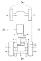
- FIG. 1 is a side view conceptually showing a forklift according to an embodiment of the present invention.
- FIG. 2 is a bottom view of the forklift shown in FIG.
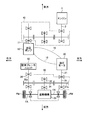
- FIG. 3 is a skeleton diagram showing a powertrain from the engine to the wheels of the forklift shown in FIG.
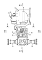
- FIG. 4 is a plan view conceptually showing components from an engine to an axle of the forklift shown in FIG.
- FIG. 5 is a cross-sectional view taken along line AA in FIG.
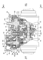
- FIG. 6 is a partially broken plan view of the transfer device applied to the forklift shown in FIG.
- the forklift illustrated here travels with the front wheel FW as a drive wheel and the rear wheel RW as a steered wheel, and performs lifting and lowering and transportation of luggage by a fork F provided in front of the vehicle body B.
- the forklift includes an engine 1 at a position substantially at the center of a vehicle body B, and a hydraulic pump 10, a hydraulic motor 20, and a transfer device 30 between the engine 1 and a front axle FA.
- the engine 1 is an internal combustion engine driven by burning fuel such as gasoline, and as shown in FIGS. 2 to 4, the engine output shaft 2 is along the front and rear of the vehicle body B and substantially in the center of the vehicle B in the left and right direction.
- the engine output shaft 2 is mounted on the vehicle body B in a state where the end of the engine output shaft 2 is directed to the front of the vehicle body B.
- the hydraulic pump 10 is a variable displacement type, and as shown in FIG. 3, the vehicle body B with the pump input shaft 11 being along the front and rear of the vehicle body B and the tip of the pump input shaft 11 being directed rearward of the vehicle body B Mounted on the.
- the pump input shaft 11 of the hydraulic pump 10 is disposed offset to the upper right of the vehicle body B with respect to the engine output shaft 2 as shown in FIG.
- the pump input shaft 11 and the engine output shaft 2 are connected via the speed reduction mechanism 40, and the pump operation is performed when the engine 1 is driven. Do.
- the hydraulic motor 20 is of a variable displacement type, and as shown in FIG. 3, the vehicle body B with the motor output shaft 21 extending along the front and rear of the vehicle body B and the tip of the motor output shaft 21 facing the front of the vehicle body B. Mounted on the. As shown in FIG. 5, the motor output shaft 21 of the hydraulic motor 20 with respect to the pump input shaft 11 so that the motor case 22 of the hydraulic motor 20 does not contact the pump case 12 of the hydraulic pump 10 mutually. It is arranged offset to the lower left of the vehicle body B. As shown in FIG. 3, the hydraulic motor 20 constitutes a hydraulic transmission mechanism called HST (Hydro-Static Transmission) by connecting the hydraulic pump 10 to the hydraulic pump 10 with a hydraulic closed circuit 15, It is driven by the oil supplied from the hydraulic pump 10.
- HST Hydro-Static Transmission
- the transfer device 30 is configured with the motor output shaft 21 of the hydraulic motor 20 as an input, and distributes and transmits the power output from the motor output shaft 21 to the left and right front axles FA, A main input shaft (first input shaft) 31, a differential input shaft (second input shaft) 32, and a differential mechanism 33 are provided.
- the main input shaft 31 has a main input gear (input gear) 31a at its base end and a spline 31b at its outer periphery, and is transferred via ball bearings 31c and 31d.
- the case 130 is rotatably supported.
- the main input gear 31 a is a helical gear and is integrally formed with the main input shaft 31.
- the main input shaft 31 has its front end directed rearward of the vehicle body B and is spline-connected to the motor output shaft 21 via a spline 31b at the front end, and is disposed on the same axial center as the motor output shaft 21 .
- the differential input shaft 32 has a differential input gear 32a at its base end and a spline 32b at its outer periphery, and is rotatably supported by the transfer case 130 via taper roller bearings 32c and 32d. .
- the differential input gear 32 a is a bevel gear and is integrally formed with the differential input shaft 32.
- the differential input shaft 32 has a base end directed to the front of the vehicle body B, and is disposed offset to the right of the vehicle body B at the same height with respect to the main input shaft 31 (see FIG. 5) is there.
- a transfer gear 34 is disposed on the spline 32 b of the differential input shaft 32.
- the transfer gear 34 is a helical gear which is splined to the differential input shaft 32 and meshes with the main input gear 31a of the main input shaft 31. When the main input shaft 31 rotates, the transfer gear 34 decelerates the differential input shaft 32. To rotate.
- a ring gear 331 of the differential mechanism 33 meshes with the differential input gear 32 a of the differential input shaft 32.
- the differential mechanism 33 includes a carrier 332, two side gears 333 and a plurality of pinion gears 334, as in the case of the conventional one, and the rotation of the differential input gear 32a is performed by the carrier 332, pinion gears 334 and respective side gears.
- 333 is transmitted to the front axle FA.
- the carrier 332 is disposed rotatably about an axis with respect to the front axle FA, and is connected to the ring gear 331.
- the side gears 333 are bevel gears connected to the front axles FA and arranged to face each other in the carrier 332.
- the pinion gear 334 is a bevel gear disposed on the carrier 332 via the pinion shaft 335 so as to revolve around the axis of the front axle FA and to be capable of rotating about its own axis.
- the two side gears 333 mesh with each other.
- an idle shaft 35 is provided on the transfer case 130 so as to be parallel to the differential input shaft 32.
- the idle shaft 35 has an idle input gear 35a at its base end, and a spline 35b at its outer periphery, and is rotatably supported by the transfer case 130 via ball bearings 35c and 35d.
- the idle input gear 35a is a helical gear that meshes with the differential input gear 32a of the differential input shaft 32, accelerates the rotation of the differential input shaft 32, and inputs the acceleration to the idle shaft 35, and is integrated with the idle shaft 35. It is molded. As shown in FIG.
- the idle shaft 35 is offset to the lower right of the vehicle body B with respect to the differential input shaft 32 in a state where the front end is directed to the rear of the vehicle body B along the front and rear of the vehicle body B. It is disposed almost directly below the hydraulic pump 10.
- a parking brake unit 50 and a friction gear mechanism 60 are formed on the idle shaft 35.
- the parking brake unit 50 is provided with a drum 51 splined to the spline 35b of the idle shaft 35, and a brake shoe 52 attached to the transfer case 130 and capable of coming into close contact with the inner circumferential surface of the drum 51; It is a drum type provided with a brake spring (not shown) which presses 52 toward the inner peripheral surface of the drum 51.
- a dust cover 53 is provided on the outer peripheral portion of the drum 51. The dust cover 53 is configured to largely project to the rear side of the vehicle body B with respect to the transfer case 130.
- the idle shaft 35 is offset to the lower right of the vehicle body B with respect to the differential input shaft 32. Therefore, the motor case 22 of the hydraulic motor 20 and the pump case 12 of the hydraulic pump 10 do not contact each other.
- parking brake unit 50 In the normal state, parking brake unit 50 is in a state where brake shoe 52 is pressed against the inner peripheral surface of drum 51 by the pressing force of the brake spring (not shown), and prevents the rotation of idle shaft 35 relative to transfer case 130 doing.
- the parking brake unit 50 is released, and the brake shoe 52 is separated from the inner circumferential surface of the drum 51 against the pressing force of the brake spring (not shown). As a result, the idle shaft 35 and the drum 51 can rotate with respect to the transfer case 130.
- the friction gear mechanism 60 is for removing the backlash between the transfer gear 34 of the differential input shaft 32 and the idle input gear 35a of the idle shaft 35, and includes the sub input gear 61 and the pair of pressure rings 62, 63.
- the sub input gear 61 is a thin plate-like gear which is disposed rotatably with respect to the idle shaft 35 and meshes with the transfer gear 34.
- the sub input gear 61 is, for example, a shift gear configured to have one more gear than the idle input gear 35a so that the number of teeth is different with respect to the idle input gear 35a, and friction plates 64 and 65 are provided on both end faces.
- the pair of pressing rings 62 and 63 is an annular member having an inner diameter larger than the outer diameter of the axial portion of the idle shaft 35.
- the pressure rings 62 and 63 are disposed between the C-ring 68 fitted on the outer periphery of the idle shaft 35 and the sub input gear 61 with the pressure springs 66 and 67 interposed therebetween. It is The pressure springs 66, 67 press the sub input gear 61 against the end face of the idle input gear 35a via one of the pressure rings 62, 63.
- the hydraulic pump 10 when the engine 1 is operated, the hydraulic pump 10 is driven via the reduction mechanism 40, and oil is supplied from the hydraulic pump 10 to the hydraulic motor 20.
- the hydraulic motor 20 supplied with oil from the hydraulic pump 10 is rotated, and the rotation of the motor output shaft 21 corresponds to the main input shaft 31, the main input gear 31a, and the transfer. It is transmitted to the carrier 332 of the differential mechanism 33 through the gear 34 and the differential input gear 32a, and is distributed to the two front axles FA through the pinion gear 334 and the side gear 333.
- the forklift travels forward.
- the hydraulic motor 20 rotates in the reverse direction
- the front axle FA also rotates in the reverse direction, and the forklift retracts.
- the idle shaft 35 constituting the parking brake unit 50 also rotates with respect to the transfer case 130.
- rattling noise occurs when the rotation of the differential input shaft 32 occurs. May occur.
- the idle input gear 35a meshes with the transfer gear 34 without backlash by the action of the sub input gear 61 press-contacted to the idle input gear 35a via the friction plates 64 and 65. That is, the sub input gear 61 configured to have a large number of teeth with respect to the idle input gear 35 a rotates slowly with respect to the idle input gear 35 a and holds the transfer gear 34 with the idle input gear 35 a.
- the idle input gear 35a meshes with the transfer gear 34 without backlash. Therefore, even when the rotational fluctuation occurs in the differential input shaft 32, it is possible to follow the rotation of the differential input shaft 32 without generating a rattling noise.
- the transfer gear 34 and the idle input gear 35 a are configured to accelerate the rotation of the differential input shaft 32 and transmit the rotation to the idle shaft 35. Therefore, in the parking brake unit 50, the rotation of the differential input shaft 32 can be more reliably prevented by the small braking torque, and the drum 51 can be miniaturized while the braking force is sufficiently ensured. It becomes possible.
- the idle shaft 35 constituting the parking brake unit 50 is disposed in parallel to the differential input shaft 32 of the power train from the hydraulic motor 20 to the differential mechanism 33, and affects the overall length of the power train. It is not a thing.
- the hydraulic motor 20, the hydraulic pump 10, and the engine 1 can be disposed closer to the front axle FA, for example, as compared with the main input shaft 31 provided with the parking brake unit 50.
- the provision of the parking brake unit 50 does not cause the wheel base to become longer.
- a forklift traveling as a front wheel FW as a driving wheel and a rear wheel RW as a steering wheel is exemplified, but the driving method is not limited to this.
- the forklift equipped with HST is illustrated, it is possible to apply not only to what was necessarily equipped with HST but also to one equipped with a transmission configured by a plurality of gear trains.
- the so-called drum type is illustrated as the parking brake unit 50, other braking devices may be applied.
- the idle shaft 35 is disposed at a position equal to or less than the height of the differential input shaft 32, maintenance of the parking brake unit 50 can be easily performed from the lower side of the vehicle body B Although there is, it is not necessarily limited to this arrangement.
Abstract
Description
30 トランスファ装置
31 メイン入力軸
31a メイン入力ギヤ
32 デフ入力軸
32a デフ入力ギヤ
33 差動機構
34 トランスファギヤ
35 アイドル軸
35a アイドル入力ギヤ
40 減速機構
50 駐車ブレーキユニット
60 フリクションギヤ機構
61 サブ入力ギヤ
62,63 押圧リング
64,65 摩擦プレート
66,67 押圧スプリング
130 トランスファケース
331 リングギヤ
332 キャリヤ
333 サイドギヤ
334 ピニオンギヤ
335 ピニオンシャフト
FA フロントフロントアクスル
Claims (5)
- 動力源によって回転駆動される第1入力軸と、前記第1入力軸の回転によって回転する第2入力軸と、前記第2入力軸からアクスルに至る間に構成した差動機構とを備え、動力源の動力を前記第1入力軸、前記第2入力軸及び差動機構を介して前記アクスルに伝達することにより走行するフォークリフトにおいて、
前記第2入力軸に対して平行となるようにアイドル軸を配設するとともに、前記第2入力軸と前記アイドル軸との間にギヤの噛合による動力伝達機構を介在させ、さらに前記アイドル軸に駐車ブレーキユニットを構成したことを特徴とするフォークリフト。 A power source includes a first input shaft rotationally driven by a power source, a second input shaft rotated by rotation of the first input shaft, and a differential mechanism configured between the second input shaft and the axle, In a forklift traveling by transmitting power of a source to the axle through the first input shaft, the second input shaft and a differential mechanism,
An idle shaft is disposed parallel to the second input shaft, and a power transmission mechanism by gear engagement is interposed between the second input shaft and the idle shaft, and the idle shaft is further connected to the idle shaft. A forklift comprising a parking brake unit. - 前記動力伝達機構は、前記第2入力軸にトランスファギヤを設ける一方、前記アイドル軸にフリクションギヤ機構を備えたアイドル入力ギヤを設け、前記アイドル入力ギヤをトランスファギヤに歯合させたことを特徴とする請求項1に記載のフォークリフト。 The power transmission mechanism is characterized in that a transfer gear is provided on the second input shaft, and an idle input gear having a friction gear mechanism is provided on the idle shaft, and the idle input gear is meshed with the transfer gear. The forklift according to claim 1.
- 前記動力伝達機構は、前記第2入力軸の回転を増速して前記アイドル軸に伝達するものであることを特徴とする請求項1に記載のフォークリフト。 The forklift according to claim 1, wherein the power transmission mechanism accelerates the rotation of the second input shaft and transmits the rotation to the idle shaft.
- 前記第1入力軸に入力ギヤを設け、前記入力ギヤを前記トランスファギヤに歯合させたことを特徴とする請求項1に記載のフォークリフト。 The forklift according to claim 1, wherein the first input shaft is provided with an input gear, and the input gear is meshed with the transfer gear.
- 前記第2入力軸の高さ以下となる位置に前記アイドル軸を配設したことを特徴とする請求項1に記載のフォークリフト。 The forklift according to claim 1, wherein the idle shaft is disposed at a position equal to or less than the height of the second input shaft.
Priority Applications (3)
| Application Number | Priority Date | Filing Date | Title |
|---|---|---|---|
| CN201180017391.2A CN102821994B (en) | 2010-08-31 | 2011-07-21 | Forklift |
| US13/637,797 US8573349B2 (en) | 2010-08-31 | 2011-07-21 | Forklift |
| DE112011100878T DE112011100878B4 (en) | 2010-08-31 | 2011-07-21 | fork-lift truck |
Applications Claiming Priority (2)
| Application Number | Priority Date | Filing Date | Title |
|---|---|---|---|
| JP2010-194759 | 2010-08-31 | ||
| JP2010194759A JP5063760B2 (en) | 2010-08-31 | 2010-08-31 | forklift |
Publications (1)
| Publication Number | Publication Date |
|---|---|
| WO2012029429A1 true WO2012029429A1 (en) | 2012-03-08 |
Family
ID=45772539
Family Applications (1)
| Application Number | Title | Priority Date | Filing Date |
|---|---|---|---|
| PCT/JP2011/066570 WO2012029429A1 (en) | 2010-08-31 | 2011-07-21 | Forklift |
Country Status (5)
| Country | Link |
|---|---|
| US (1) | US8573349B2 (en) |
| JP (1) | JP5063760B2 (en) |
| CN (1) | CN102821994B (en) |
| DE (1) | DE112011100878B4 (en) |
| WO (1) | WO2012029429A1 (en) |
Families Citing this family (5)
| Publication number | Priority date | Publication date | Assignee | Title |
|---|---|---|---|---|
| US8459137B1 (en) * | 2010-04-07 | 2013-06-11 | Hydro-Gear Limited Partnership | Control assembly for drive system |
| JP5063760B2 (en) * | 2010-08-31 | 2012-10-31 | 株式会社小松製作所 | forklift |
| US8936130B2 (en) * | 2011-03-29 | 2015-01-20 | Komatsu Ltd. | Electric forklift |
| CN103522885A (en) * | 2013-11-01 | 2014-01-22 | 安徽合力股份有限公司 | Double-motor driving device with parking brake of electric forklift |
| US10106131B2 (en) | 2014-12-25 | 2018-10-23 | Mitsubishi Logisnext Co., LTD. | Axle of industrial vehicle |
Citations (4)
| Publication number | Priority date | Publication date | Assignee | Title |
|---|---|---|---|---|
| JPS59145455U (en) * | 1983-03-19 | 1984-09-28 | 株式会社神崎高級工機製作所 | parking brake device |
| JPH05215200A (en) * | 1992-02-03 | 1993-08-24 | Daikin Ind Ltd | Mechanical hydraulic transmission |
| JP2005054888A (en) * | 2003-08-04 | 2005-03-03 | Honda Motor Co Ltd | Vehicular transmission |
| WO2006095813A1 (en) * | 2005-03-10 | 2006-09-14 | Tcm Corporation | Hydraulic power transmission device and work vehicle |
Family Cites Families (23)
| Publication number | Priority date | Publication date | Assignee | Title |
|---|---|---|---|---|
| JPS5840470U (en) * | 1981-09-12 | 1983-03-17 | 株式会社クボタ | Riding rice transplanter |
| US4932209A (en) * | 1988-02-03 | 1990-06-12 | Kanzaki Kokyukoki Mf. Co. Ltd. | Axle driving apparatus |
| US5190435A (en) * | 1988-11-29 | 1993-03-02 | Washington Chain And Supply, Inc. | Fork lift truck |
| DE4325211B8 (en) | 1993-07-27 | 2006-06-01 | Kanzaki Kokyukoki Mfg. Co., Ltd., Amagasaki | Axle assembly with locking mechanism and its use for a self-propelled cleaning machine |
| US6390227B1 (en) * | 1995-03-30 | 2002-05-21 | Kanzaki Kokyukoki Mfg. Co., Ltd. | Axle driving unit for a lawn tractor |
| JPH10147220A (en) | 1996-11-19 | 1998-06-02 | Nissan Motor Co Ltd | Parking brake structure |
| CA2234927C (en) * | 1997-04-25 | 2003-05-27 | Kabushiki Kaisha Toyoda Jidoshokki Seisakusho | Mounting structure for wheel angle detector and rotation amount detector for vehicle wheel |
| US6129169A (en) * | 1997-06-06 | 2000-10-10 | Sauer Inc. | Mobile work vehicle with compact axle assembly |
| JP3129259B2 (en) * | 1997-10-31 | 2001-01-29 | 株式会社豊田自動織機製作所 | Axle swing control method and axle swing control device for industrial vehicle |
| DE69942245D1 (en) * | 1998-06-05 | 2010-05-27 | Kanzaki Kokyukoki Mfg Co Ltd | HYDROSTATIC MOTOR VEHICLE DRIVE AND PRESSURE SOURCE PROVIDED THEREFOR |
| EP1118581A1 (en) * | 1999-05-07 | 2001-07-25 | TCM Corporation | Hydraulic-driven fork lift |
| US6604601B2 (en) * | 2001-10-22 | 2003-08-12 | Biomet-Ross, Inc. | Lift truck drive train |
| DE60305771T2 (en) * | 2002-04-03 | 2007-06-14 | Kanzaki Kokyukoki Mfg. Co., Ltd., Amagasaki | Pump and work vehicle |
| US7044258B2 (en) * | 2002-04-05 | 2006-05-16 | Cnh America Llc | Direct drive suspension |
| JP2005155686A (en) * | 2003-11-20 | 2005-06-16 | Kanzaki Kokyukoki Mfg Co Ltd | Axle driving device and four-wheel drive vehicle equipped with it |
| JP2006153033A (en) * | 2004-11-25 | 2006-06-15 | Kanzaki Kokyukoki Mfg Co Ltd | Pumping device and hydraulic continuously variable transmission |
| US7610985B2 (en) * | 2005-05-18 | 2009-11-03 | Kanzaki Kokyukoki Mfg. Co., Ltd. | HST unit |
| JP4793134B2 (en) * | 2005-09-30 | 2011-10-12 | 株式会社豊田自動織機 | Forklift travel control device |
| JP4609390B2 (en) * | 2005-09-30 | 2011-01-12 | 株式会社豊田自動織機 | Forklift travel control device |
| US20070137918A1 (en) * | 2005-11-23 | 2007-06-21 | Xingen Dong | Mounting of hydrostatic transmission for riding lawn mower |
| JP5016421B2 (en) * | 2007-09-10 | 2012-09-05 | 株式会社クボタ | Work vehicle transmission structure |
| DE102008034242A1 (en) | 2008-07-23 | 2010-01-28 | Linde Material Handling Gmbh | Traction drive for drive machine, particularly ground conveyor, has combustion engine and hydrostatic drive, where electric motor is provided in mechanical drive connection, and electrical engine is connected to electrical energy storage |
| JP5063760B2 (en) * | 2010-08-31 | 2012-10-31 | 株式会社小松製作所 | forklift |
-
2010
- 2010-08-31 JP JP2010194759A patent/JP5063760B2/en not_active Expired - Fee Related
-
2011
- 2011-07-21 WO PCT/JP2011/066570 patent/WO2012029429A1/en active Application Filing
- 2011-07-21 CN CN201180017391.2A patent/CN102821994B/en not_active Expired - Fee Related
- 2011-07-21 DE DE112011100878T patent/DE112011100878B4/en not_active Expired - Fee Related
- 2011-07-21 US US13/637,797 patent/US8573349B2/en not_active Expired - Fee Related
Patent Citations (4)
| Publication number | Priority date | Publication date | Assignee | Title |
|---|---|---|---|---|
| JPS59145455U (en) * | 1983-03-19 | 1984-09-28 | 株式会社神崎高級工機製作所 | parking brake device |
| JPH05215200A (en) * | 1992-02-03 | 1993-08-24 | Daikin Ind Ltd | Mechanical hydraulic transmission |
| JP2005054888A (en) * | 2003-08-04 | 2005-03-03 | Honda Motor Co Ltd | Vehicular transmission |
| WO2006095813A1 (en) * | 2005-03-10 | 2006-09-14 | Tcm Corporation | Hydraulic power transmission device and work vehicle |
Also Published As
| Publication number | Publication date |
|---|---|
| US20130146384A1 (en) | 2013-06-13 |
| JP5063760B2 (en) | 2012-10-31 |
| DE112011100878T5 (en) | 2013-03-07 |
| DE112011100878B4 (en) | 2013-10-31 |
| JP2012051442A (en) | 2012-03-15 |
| CN102821994B (en) | 2013-09-11 |
| US8573349B2 (en) | 2013-11-05 |
| CN102821994A (en) | 2012-12-12 |
Similar Documents
| Publication | Publication Date | Title |
|---|---|---|
| JP4319131B2 (en) | Transmission with simple structure | |
| JP4745279B2 (en) | Axle device with built-in transmission to prevent reverse travel on uphill slopes | |
| WO2012029429A1 (en) | Forklift | |
| WO2006090946A1 (en) | Compact transmission preventing a vehicle from moving backward on a slope | |
| US7029415B2 (en) | Differential apparatus | |
| JP7028141B2 (en) | Transfer for four-wheel drive vehicles | |
| JPH11315905A (en) | Differential device | |
| JP5498707B2 (en) | Combined differential limiter | |
| JPH0663556B2 (en) | Automatic transmission for four-wheel drive vehicles | |
| JP5187170B2 (en) | Torque limiter and driving force transmission device | |
| JP4657269B2 (en) | Transfer device | |
| JP4376745B2 (en) | Driving force distribution device for four-wheel drive vehicle | |
| JP2012192765A (en) | Motor type vehicle drive apparatus | |
| KR20140015637A (en) | Two-stage electric axle apparatus for forward and backward driving | |
| KR100786533B1 (en) | 4-wheel drive center axle disconnect system | |
| KR102067535B1 (en) | Driving motor integrated transmission | |
| JP2005054829A (en) | Power transmission device and center differential device | |
| JP6500287B2 (en) | Wet brake system | |
| KR20220054477A (en) | Driving force distribution device | |
| JP4767233B2 (en) | Power transmission path of four-wheel drive vehicle and control device for this power transmission system | |
| JP2002266982A (en) | Differential device | |
| JPS6233151Y2 (en) | ||
| CN111186488A (en) | Tracked vehicle turns to device | |
| JPH10953A (en) | Symmetrical driving force distributor | |
| JP2008307923A (en) | Driving force distribution device |
Legal Events
| Date | Code | Title | Description |
|---|---|---|---|
| WWE | Wipo information: entry into national phase |
Ref document number: 201180017391.2 Country of ref document: CN |
|
| 121 | Ep: the epo has been informed by wipo that ep was designated in this application |
Ref document number: 11821447 Country of ref document: EP Kind code of ref document: A1 |
|
| WWE | Wipo information: entry into national phase |
Ref document number: 112011100878 Country of ref document: DE Ref document number: 1120111008783 Country of ref document: DE |
|
| WWE | Wipo information: entry into national phase |
Ref document number: 13637797 Country of ref document: US |
|
| 122 | Ep: pct application non-entry in european phase |
Ref document number: 11821447 Country of ref document: EP Kind code of ref document: A1 |