JP5063760B2 - forklift - Google Patents
forklift Download PDFInfo
- Publication number
- JP5063760B2 JP5063760B2 JP2010194759A JP2010194759A JP5063760B2 JP 5063760 B2 JP5063760 B2 JP 5063760B2 JP 2010194759 A JP2010194759 A JP 2010194759A JP 2010194759 A JP2010194759 A JP 2010194759A JP 5063760 B2 JP5063760 B2 JP 5063760B2
- Authority
- JP
- Japan
- Prior art keywords
- input shaft
- shaft
- gear
- idle
- vehicle body
- Prior art date
- Legal status (The legal status is an assumption and is not a legal conclusion. Google has not performed a legal analysis and makes no representation as to the accuracy of the status listed.)
- Expired - Fee Related
Links
- 230000005540 biological transmission Effects 0.000 claims description 10
- 238000003825 pressing Methods 0.000 description 7
- 230000002093 peripheral effect Effects 0.000 description 4
- 238000004519 manufacturing process Methods 0.000 description 3
- 239000000428 dust Substances 0.000 description 2
- 238000002485 combustion reaction Methods 0.000 description 1
- 238000010586 diagram Methods 0.000 description 1
- 238000006073 displacement reaction Methods 0.000 description 1
- 239000000446 fuel Substances 0.000 description 1
- 230000002706 hydrostatic effect Effects 0.000 description 1
- 238000000034 method Methods 0.000 description 1
- 230000032258 transport Effects 0.000 description 1
Images


Classifications
-
- B—PERFORMING OPERATIONS; TRANSPORTING
- B60—VEHICLES IN GENERAL
- B60T—VEHICLE BRAKE CONTROL SYSTEMS OR PARTS THEREOF; BRAKE CONTROL SYSTEMS OR PARTS THEREOF, IN GENERAL; ARRANGEMENT OF BRAKING ELEMENTS ON VEHICLES IN GENERAL; PORTABLE DEVICES FOR PREVENTING UNWANTED MOVEMENT OF VEHICLES; VEHICLE MODIFICATIONS TO FACILITATE COOLING OF BRAKES
- B60T1/00—Arrangements of braking elements, i.e. of those parts where braking effect occurs specially for vehicles
- B60T1/02—Arrangements of braking elements, i.e. of those parts where braking effect occurs specially for vehicles acting by retarding wheels
- B60T1/06—Arrangements of braking elements, i.e. of those parts where braking effect occurs specially for vehicles acting by retarding wheels acting otherwise than on tread, e.g. employing rim, drum, disc, or transmission or on double wheels
- B60T1/062—Arrangements of braking elements, i.e. of those parts where braking effect occurs specially for vehicles acting by retarding wheels acting otherwise than on tread, e.g. employing rim, drum, disc, or transmission or on double wheels acting on transmission parts
-
- B—PERFORMING OPERATIONS; TRANSPORTING
- B66—HOISTING; LIFTING; HAULING
- B66F—HOISTING, LIFTING, HAULING OR PUSHING, NOT OTHERWISE PROVIDED FOR, e.g. DEVICES WHICH APPLY A LIFTING OR PUSHING FORCE DIRECTLY TO THE SURFACE OF A LOAD
- B66F9/00—Devices for lifting or lowering bulky or heavy goods for loading or unloading purposes
- B66F9/06—Devices for lifting or lowering bulky or heavy goods for loading or unloading purposes movable, with their loads, on wheels or the like, e.g. fork-lift trucks
- B66F9/075—Constructional features or details
-
- B—PERFORMING OPERATIONS; TRANSPORTING
- B60—VEHICLES IN GENERAL
- B60K—ARRANGEMENT OR MOUNTING OF PROPULSION UNITS OR OF TRANSMISSIONS IN VEHICLES; ARRANGEMENT OR MOUNTING OF PLURAL DIVERSE PRIME-MOVERS IN VEHICLES; AUXILIARY DRIVES FOR VEHICLES; INSTRUMENTATION OR DASHBOARDS FOR VEHICLES; ARRANGEMENTS IN CONNECTION WITH COOLING, AIR INTAKE, GAS EXHAUST OR FUEL SUPPLY OF PROPULSION UNITS IN VEHICLES
- B60K17/00—Arrangement or mounting of transmissions in vehicles
- B60K17/04—Arrangement or mounting of transmissions in vehicles characterised by arrangement, location, or kind of gearing
- B60K17/10—Arrangement or mounting of transmissions in vehicles characterised by arrangement, location, or kind of gearing of fluid gearing
- B60K17/105—Units comprising at least a part of the gearing and a torque-transmitting axle, e.g. transaxles
-
- B—PERFORMING OPERATIONS; TRANSPORTING
- B66—HOISTING; LIFTING; HAULING
- B66F—HOISTING, LIFTING, HAULING OR PUSHING, NOT OTHERWISE PROVIDED FOR, e.g. DEVICES WHICH APPLY A LIFTING OR PUSHING FORCE DIRECTLY TO THE SURFACE OF A LOAD
- B66F9/00—Devices for lifting or lowering bulky or heavy goods for loading or unloading purposes
- B66F9/06—Devices for lifting or lowering bulky or heavy goods for loading or unloading purposes movable, with their loads, on wheels or the like, e.g. fork-lift trucks
- B66F9/075—Constructional features or details
- B66F9/07509—Braking
-
- B—PERFORMING OPERATIONS; TRANSPORTING
- B66—HOISTING; LIFTING; HAULING
- B66F—HOISTING, LIFTING, HAULING OR PUSHING, NOT OTHERWISE PROVIDED FOR, e.g. DEVICES WHICH APPLY A LIFTING OR PUSHING FORCE DIRECTLY TO THE SURFACE OF A LOAD
- B66F9/00—Devices for lifting or lowering bulky or heavy goods for loading or unloading purposes
- B66F9/06—Devices for lifting or lowering bulky or heavy goods for loading or unloading purposes movable, with their loads, on wheels or the like, e.g. fork-lift trucks
- B66F9/075—Constructional features or details
- B66F9/07572—Propulsion arrangements
-
- B—PERFORMING OPERATIONS; TRANSPORTING
- B60—VEHICLES IN GENERAL
- B60Y—INDEXING SCHEME RELATING TO ASPECTS CROSS-CUTTING VEHICLE TECHNOLOGY
- B60Y2200/00—Type of vehicle
- B60Y2200/60—Industrial applications, e.g. pipe inspection vehicles
- B60Y2200/62—Conveyors, floor conveyors
Description
本発明は、フォークリフトに関するもので、特に、駐車ブレーキユニットの配置位置に関するものである。 The present invention relates to a forklift, and more particularly to an arrangement position of a parking brake unit.
フォークリフトの駐車ブレーキユニットとしては、変速機から差動機構に至るパワートレインに設けるようにしたものがある(例えば、特許文献1参照)。駐車ブレーキユニットは、複数の車輪に制動を掛けることが好ましいが、個々の車輪に対して設けたのでは組み立て作業や製造コストの点で不利となる。これに対して、上述のように、差動機構に至るパワートレインに駐車ブレーキユニットを設ければ、単一であっても複数の車輪に対して制動を掛けた状態とすることができる。これにより、個々の車輪に駐車ブレーキユニットを設ける場合に比べて取扱い部品点数を削減し、製造作業の容易化や製造コストの低減を図ることが可能となる。 As a parking brake unit of a forklift, there is one that is provided in a power train from a transmission to a differential mechanism (see, for example, Patent Document 1). The parking brake unit preferably brakes a plurality of wheels. However, providing the parking brake unit for each wheel is disadvantageous in terms of assembly work and manufacturing cost. On the other hand, as described above, if a parking brake unit is provided in the power train that reaches the differential mechanism, even if a parking brake unit is provided, a plurality of wheels can be braked. Thereby, compared with the case where a parking brake unit is provided for each wheel, the number of parts to be handled can be reduced, and the manufacturing operation can be facilitated and the manufacturing cost can be reduced.
しかしながら、上述したフォークリフトにあっては、駐車ブレーキユニットを個々の車輪に対して設けたものに比べて、パワートレインの全長が増大することになり、例えばホイールベースの長大化を招来する要因となる。ホイールベースの長大化は、旋回半径を増大させる要因となるものであり、フォークリフトの性能を考慮した場合、好ましいとはいえない。 However, in the forklift described above, the total length of the power train is increased as compared with the case where the parking brake unit is provided for each wheel, which causes an increase in the length of the wheel base, for example. . Increasing the length of the wheel base is a factor that increases the turning radius, and is not preferable in consideration of the performance of the forklift.
本発明は、上記実情に鑑みて、ホイールベースの長大化を招来することなく駐車ブレーキユニットの取扱い部品点数を削減することのできるフォークリフトを提供することを目的とする。 In view of the above circumstances, an object of the present invention is to provide a forklift capable of reducing the number of parts handled in a parking brake unit without causing an increase in the length of a wheel base.
上記目的を達成するため、本発明に係るフォークリフトは、ポンプ入力軸が車体の前後に沿い、かつ前記ポンプ入力軸の先端が前記車体の後方に向いた状態で前記車体に搭載した油圧ポンプと、モータ出力軸が前記車体の前後に沿い、かつ前記モータ出力軸の先端が前記車体の前方に向いた状態で前記車体に搭載し、前記油圧ポンプから供給される油によって駆動される油圧モータと、前記油圧モータのモータ出力軸に対して同一の軸心上となる位置に回転可能に配設し、前記油圧モータによって回転駆動される第1入力軸と、前記第1入力軸の回転によって回転する第2入力軸と、前記第2入力軸から、前記車体の左右方向に沿って配設したアクスルに至る間に構成した差動機構とを備え、前記油圧モータの動力を前記第1入力軸、前記第2入力軸及び前記差動機構を介して前記アクスルに伝達することにより走行するフォークリフトであって、前記モータ出力軸が前記ポンプ入力軸に対して前記車体の左下方にオフセットするように前記油圧モータを配置するとともに、前記第1入力軸に対して平行となる姿勢で前記第2入力軸を前記第1入力軸に並設し、さらに前記第1入力軸及び前記第2入力軸のそれぞれに対してオフセットし、かつ前記油圧ポンプの前記ポンプ入力軸よりも下方となる位置に前記第2入力軸に平行となるようにアイドル軸を配設するとともに、前記第2入力軸と前記アイドル軸との間にギヤの噛合による動力伝達機構を介在させ、前記アイドル軸に駐車ブレーキユニットを構成したことを特徴とする。 In order to achieve the above object, a forklift according to the present invention includes a hydraulic pump mounted on the vehicle body with a pump input shaft along the front and rear of the vehicle body and a tip of the pump input shaft facing the rear of the vehicle body, A hydraulic motor mounted on the vehicle body with a motor output shaft along the front and rear of the vehicle body and a tip of the motor output shaft facing the front of the vehicle body, and driven by oil supplied from the hydraulic pump; A first input shaft that is rotatably disposed at a position that is on the same axial center with respect to the motor output shaft of the hydraulic motor, and is rotated by the rotation of the first input shaft. A second input shaft, and a differential mechanism configured to extend from the second input shaft to an axle disposed along the left-right direction of the vehicle body, and the power of the hydraulic motor is transmitted to the first input shaft, Said A forklift travels by the input shaft and through the differential mechanism for transmitting to said axle, said hydraulic motor so that the motor output shaft is offset on the lower left side of the vehicle body relative to the pump input shaft And arranging the second input shaft in parallel with the first input shaft in a posture parallel to the first input shaft, and further with respect to each of the first input shaft and the second input shaft. An idle shaft is disposed at a position that is offset and below the pump input shaft of the hydraulic pump so as to be parallel to the second input shaft, and between the second input shaft and the idle shaft. A power transmission mechanism by gear meshing is interposed between the two and a parking brake unit is configured on the idle shaft.
また、本発明は、上述したフォークリフトにおいて、前記動力伝達機構は、前記第2入力軸にトランスファギヤを設ける一方、前記アイドル軸にフリクションギヤ機構を備えたアイドル入力ギヤを設け、前記アイドル入力ギヤをトランスファギヤに歯合させたことを特徴とする。 In the forklift described above, the power transmission mechanism may include a transfer gear on the second input shaft, an idle input gear having a friction gear mechanism on the idle shaft, and the idle input gear. It is characterized by meshing with the transfer gear.
また、本発明は、上述したフォークリフトにおいて、前記動力伝達機構は、前記第2入力軸の回転を増速して前記アイドル軸に伝達するものであることを特徴とする。 In the forklift described above, the power transmission mechanism may increase the rotation of the second input shaft and transmit it to the idle shaft.
また、本発明は、上述したフォークリフトにおいて、前記第1入力軸に入力ギヤを設け、前記入力ギヤを前記トランスファギヤに歯合させたことを特徴とする。 In the forklift described above, an input gear is provided on the first input shaft, and the input gear is engaged with the transfer gear.
また、本発明は、上述したフォークリフトにおいて、前記第2入力軸の高さ以下となる位置に前記アイドル軸を配設したことを特徴とする。 Further, the present invention is characterized in that in the forklift described above, the idle shaft is disposed at a position equal to or lower than the height of the second input shaft.
本発明によれば、差動機構に至るパワートレインに作用するように駐車ブレーキユニットを設けているため、単一であっても複数の車輪に対して制動を掛けた状態とすることができ、取扱い部品点数の削減を図ることができる。しかも、駐車ブレーキユニットを設けるアイドル軸は、パワートレインの全長に影響を与えるものではない。従って、駐車ブレーキユニットを設けることがホイールベースの長大化を招来する要因とはならない。 According to the present invention, since the parking brake unit is provided so as to act on the power train leading to the differential mechanism, even a single wheel can be braked to a plurality of wheels, The number of parts handled can be reduced. Moreover, the idle shaft provided with the parking brake unit does not affect the overall length of the power train. Therefore, the provision of the parking brake unit does not cause the wheel base to become longer.
以下、添付図面を参照しながら本発明に係るフォークリフトの好適な実施の形態について詳細に説明する。 Hereinafter, preferred embodiments of a forklift according to the present invention will be described in detail with reference to the accompanying drawings.
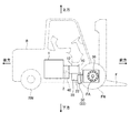
図1及び図2は、本発明の実施の形態であるフォークリフトを示したものである。ここで例示するフォークリフトは、前輪FWを駆動輪、後輪RWを操舵輪として走行し、車体Bの前方に設けたフォークFによって荷物の上げ下ろしや運搬を行うもので、車体Bのほぼ中央となる位置にエンジン1を備え、かつエンジン1とフロントアクスルFAとの間に油圧ポンプ10、油圧モータ20、トランスファ装置30を備えている。エンジン1は、ガソリン等の燃料を燃焼させて駆動する内燃機関であり、図2〜図4に示すように、エンジン出力軸2が車体Bの前後に沿い、かつ車体Bの左右方向のほぼ中央においてエンジン出力軸2の先端が車体Bの前方に向いた状態で車体Bに搭載してある。
FIG.1 and FIG.2 shows the forklift which is embodiment of this invention. The forklift illustrated here is a vehicle that travels with the front wheel FW as a driving wheel and the rear wheel RW as a steering wheel, and lifts and lowers and transports a load with a fork F provided in front of the vehicle body B. The
油圧ポンプ10は、可変容量型のもので、図3に示すように、ポンプ入力軸11が車体Bの前後に沿い、かつポンプ入力軸11の先端が車体Bの後方に向いた状態で車体Bに搭載してある。油圧ポンプ10のポンプ入力軸11は、図5に示すように、エンジン出力軸2に対して車体Bの右上方にオフセットして配置してある。この油圧ポンプ10は、図2〜図4に示すように、ポンプ入力軸11とエンジン出力軸2との間が減速機構40を介して接続してあり、エンジン1が駆動した場合にポンプ動作を行う。
The
図3に示すように、油圧モータ20は、可変容量型のもので、モータ出力軸21が車体Bの前後に沿い、かつモータ出力軸21の先端が車体Bの前方に向いた状態で車体Bに搭載してある。図5に示すように、油圧モータ20のモータ出力軸21は、油圧モータ20のモータケース22が油圧ポンプ10のポンプケース12と相互に接触することがないように、ポンプ入力軸11に対して車体Bの左下方にオフセットして配置してある。図3に示すように、この油圧モータ20は、油圧ポンプ10との間を油圧閉回路15で接続することにより、HST(Hydro−Static Transmission)と称される油圧変速機構を構成するもので、油圧ポンプ10から供給される油によって駆動される。
As shown in FIG. 3, the
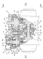
図3に示すように、トランスファ装置30は、油圧モータ20のモータ出力軸21を入力として構成し、モータ出力軸21から出力された動力を左右のフロントアクスルFAに分配して伝達するもので、メイン入力軸(第1入力軸)31、デフ入力軸(第2入力軸)32、差動機構33を備えている。
As shown in FIG. 3, the
メイン入力軸31は、図6に示すように、基端部にメイン入力ギヤ(入力ギヤ)31aを有する一方、先端部外周にスプライン31bを有したもので、ボールベアリング31c,31dを介してトランスファケース130に回転可能に支持させてある。メイン入力ギヤ31aは、はす歯歯車であり、メイン入力軸31と一体に成形してある。このメイン入力軸31は、先端を車体Bの後方に向け、先端部のスプライン31bを介してモータ出力軸21にスプライン結合してあり、モータ出力軸21と同一の軸心上に配置してある。
As shown in FIG. 6, the
デフ入力軸32は、基端部にデフ入力ギヤ32aを有する一方、中間部外周にスプライン32bを有したもので、テーパローラベアリング32c,32dを介してトランスファケース130に回転可能に支持させてある。デフ入力ギヤ32aは、かさ歯車であり、デフ入力軸32と一体に成形してある。このデフ入力軸32は、基端を車体Bの前方に向け、メイン入力軸31に対して軸心がほぼ同じ高さで、車体Bの右方にオフセットして配置してある。デフ入力軸32のスプライン32bには、トランスファギヤ34が配設してある。トランスファギヤ34は、デフ入力軸32にスプライン結合し、かつメイン入力軸31のメイン入力ギヤ31aに歯合するはす歯歯車であり、メイン入力軸31が回転した場合にデフ入力軸32を減速して回転させるものである。
The
デフ入力軸32のデフ入力ギヤ32aには、差動機構33のリングギヤ331が歯合している。差動機構33は、従前から用いられているものと同様、キャリヤ332、2つのサイドギヤ333、複数のピニオンギヤ334を備えて構成し、デフ入力ギヤ32aの回転をキャリヤ332、ピニオンギヤ334及びそれぞれのサイドギヤ333を介してフロントアクスルFAに伝達するものである。キャリヤ332は、フロントアクスルFAに対して軸心回りに回転可能に配設したもので、リングギヤ331と連結してある。サイドギヤ333は、フロントアクスルFAのそれぞれに連結し、キャリヤ332の内部において互いに対向配置したかさ歯車である。ピニオンギヤ334は、フロントアクスルFAの軸心を中心として公転し、かつ自身の軸心回りに自転可能となるように、ピニオンシャフト335を介してキャリヤ332に配設したかさ歯車であり、対向する2つのサイドギヤ333のそれぞれに歯合している。
The
一方、このフォークリフトには、デフ入力軸32に対して平行となるようにトランスファケース130にアイドル軸35が設けてある。アイドル軸35は、基端部にアイドル入力ギヤ35aを備える一方、先端部外周にスプライン35bを有したもので、ボールベアリング35c,35dを介してトランスファケース130に回転可能に支持させてある。アイドル入力ギヤ35aは、デフ入力軸32のデフ入力ギヤ32aに歯合し、デフ入力軸32の回転を増速してアイドル軸35に入力させるはす歯歯車であり、アイドル軸35と一体に成形してある。図5に示すように、このアイドル軸35は、車体Bの前後に沿い、先端を車体Bの後方に向けた状態で、デフ入力軸32に対して車体Bの右下方にオフセットすることにより、油圧ポンプ10のほぼ真下に配置してある。
On the other hand, the forklift is provided with an
アイドル軸35には、駐車ブレーキユニット50及びフリクションギヤ機構60が構成してある。駐車ブレーキユニット50は、アイドル軸35のスプライン35bにスプライン結合したドラム51と、トランスファケース130に取り付けてあり、ドラム51の内周面に対して離接可能に設けたブレーキシュー52と、ブレーキシュー52をドラム51の内周面に向けて押圧するブレーキスプリング(図示せず)とを備えて構成したドラム式のものである。ドラム51の外周部には、ダストカバー53が設けてある。ダストカバー53は、トランスファケース130に対して車体Bの後方側に大きく突出する構成であるが、上述したように、デフ入力軸32に対してアイドル軸35を車体Bの右下方にオフセットしてあるため、油圧モータ20のモータケース22や油圧ポンプ10のポンプケース12と相互に接触することはない。
A
この駐車ブレーキユニット50は、通常状態においてブレーキスプリングの押圧力でドラム51の内周面にブレーキシュー52が押し付けられた状態にあり、トランスファケース130に対するアイドル軸35の回転を阻止している。これに対して解除操作が行われると、駐車ブレーキユニット50が解除状態となり、ブレーキスプリングの押圧力に抗してブレーキシュー52がドラム51の内周面から離隔する。この結果、トランスファケース130に対してアイドル軸35がドラム51とともに回転可能状態となる。
In the normal state, the
フリクションギヤ機構60は、デフ入力軸32のトランスファギヤ34とアイドル軸35のアイドル入力ギヤ35aとの間のバックラッシュを除去するためのもので、サブ入力ギヤ61、一対の押圧リング62,63を備えている。サブ入力ギヤ61は、アイドル軸35に対して回転可能に配設し、かつトランスファギヤ34に歯合する薄板状の歯車である。このサブ入力ギヤ61は、アイドル入力ギヤ35aに対して歯数が異なるように、例えばアイドル入力ギヤ35aよりも1枚多くなるように構成した転位歯車であり、両端面に摩擦プレート64,65を備えている。一対の押圧リング62,63は、アイドル軸35の軸部の外径よりも大きな内径を有した環状部材であり、互いの間に押圧スプリング66,67を介在させた状態で、アイドル軸35の外周に嵌合させたCリング68と、サブ入力ギヤ61との間に配設してある。押圧スプリング66,67は、一方の押圧リング62,63を介してサブ入力ギヤ61をアイドル入力ギヤ35aの端面に押圧するものである。
The
上記のように構成したフォークリフトでは、エンジン1が運転されると、減速機構40を介して油圧ポンプ10が駆動し、油圧モータ20に対して油圧ポンプ10から油が供給されることとなる。
In the forklift configured as described above, when the
駐車ブレーキユニット50が解除状態にある場合には、油圧ポンプ10から油が供給された油圧モータ20が回転することになり、モータ出力軸21の回転がメイン入力軸31、メイン入力ギヤ31a、トランスファギヤ34、デフ入力ギヤ32aを介して差動機構33のキャリヤ332に伝達され、さらにピニオンギヤ334、サイドギヤ333を介して2つのフロントアクスルFAに分配伝達され、例えばフォークリフトが前進することになる。油圧モータ20が逆方向に回転すれば、フロントアクスルFAも逆方向に回転し、フォークリフトが後退する。
When the
この間、駐車ブレーキユニット50を構成したアイドル軸35もトランスファケース130に対して回転することになるが、負荷が加えられていないため、デフ入力軸32に回転変動が生じた場合に歯打ち音が発生する恐れがある。しかしながら、このフォークリフトにおいては、摩擦プレート64,65を介してアイドル入力ギヤ35aに圧接されたサブ入力ギヤ61の作用により、バックラッシュが無い状態でアイドル入力ギヤ35aがトランスファギヤ34に歯合する。すなわち、アイドル入力ギヤ35aに対して歯数が多く構成されたサブ入力ギヤ61は、アイドル入力ギヤ35aに対して回転が遅くなり、アイドル入力ギヤ35aとの間にトランスファギヤ34を挟持するように作用するため、バックラッシュが無い状態でアイドル入力ギヤ35aがトランスファギヤ34に歯合する。従って、デフ入力軸32に回転変動が生じた場合にも、歯打ち音を発生させることなくデフ入力軸32の回転に追従できるようになる。
During this time, the
一方、駐車ブレーキユニット50が通常状態にあり、トランスファケース130に対するアイドル軸35の回転が阻止された場合には、トランスファギヤ34を介してアイドル入力ギヤ35aに歯合するデフ入力軸32、さらにはメイン入力ギヤ31aを介してトランスファギヤ34に歯合するメイン入力軸31のいずれもがトランスファケース130に対して回転できる状態にない。従って、デフ入力ギヤ32a及びリングギヤ331を介してデフ入力軸32に連結されたキャリヤ332がトランスファケース130に対して回転することはなく、2つのフロントアクスルFAが同方向に向けて回転できないため、フォークリフトが駐車した状態に維持される。
On the other hand, when the
ここで、上記フォークリフトによれば、デフ入力軸32の回転を増速してアイドル軸35に伝達するようにトランスファギヤ34及びアイドル入力ギヤ35aを構成している。従って、駐車ブレーキユニット50においては、小さい制動トルクでより確実にデフ入力軸32の回転を阻止した状態に維持することができ、制動力を十分に確保した上でドラム51を小型化することが可能となる。
Here, according to the forklift, the
しかも、単一の駐車ブレーキユニット50によっても、結果的に2つの前輪FWの双方に制動を掛けた状態と同等の機能を果たすことができ、取扱い部品点数を増大させることなく駐車時の制動機能を確保できる。
Moreover, even with the single
さらに、駐車ブレーキユニット50を構成したアイドル軸35は、油圧モータ20から差動機構33に至るパワートレインのデフ入力軸32に対して並設させたものであり、パワートレインの全長に影響を与えるものではない。これにより、例えばメイン入力軸31に駐車ブレーキユニット50を設けたものに比べ、フロントアクスルFAに対して油圧モータ20、油圧ポンプ10、エンジン1をそれぞれ近接して配置することができるようになり、駐車ブレーキユニット50を設けることがホイールベースの長大化を招来する要因とはならない。
Further, the
尚、上述した実施の形態では、前輪FWを駆動輪、後輪RWを操舵輪として走行するフォークリフトを例示しているが、駆動方式はこれに限定されない。また、HSTを備えたフォークリフトを例示しているが、必ずしもHSTを備えたものに限らず、複数のギヤ列によって構成したトランスミッションを備えるものにも適用することは可能である。さらに、駐車ブレーキユニット50としては、いわゆるドラム式のものを例示しているが、その他の制動装置を適用しても構わない。
In the above-described embodiment, the forklift that travels using the front wheel FW as the driving wheel and the rear wheel RW as the steering wheel is illustrated, but the driving method is not limited thereto. Moreover, although the forklift provided with HST is illustrated, it is not necessarily limited to the one provided with HST, but can be applied to one provided with a transmission constituted by a plurality of gear trains. Furthermore, as the
また、上述した実施の形態では、デフ入力軸32の高さ以下となる位置にアイドル軸35を配設しているため、車体Bの下方から駐車ブレーキユニット50のメインテナンスを容易に行うことが可能であるが、必ずしもこの配置に限らない。
Further, in the above-described embodiment, the
20 油圧モータ
30 トランスファ装置
31 メイン入力軸
31a メイン入力ギヤ
32 デフ入力軸
32a デフ入力ギヤ
33 差動機構
34 トランスファギヤ
35 アイドル軸
35a アイドル入力ギヤ
40 減速機構
50 駐車ブレーキユニット
60 フリクションギヤ機構
61 サブ入力ギヤ
62,63 押圧リング
64,65 摩擦プレート
66,67 押圧スプリング
130 トランスファケース
331 リングギヤ
332 キャリヤ
333 サイドギヤ
334 ピニオンギヤ
335 ピニオンシャフト
FA フロントフロントアクスル
DESCRIPTION OF
Claims (5)
モータ出力軸が前記車体の前後に沿い、かつ前記モータ出力軸の先端が前記車体の前方に向いた状態で前記車体に搭載し、前記油圧ポンプから供給される油によって駆動される油圧モータと、
前記油圧モータのモータ出力軸に対して同一の軸心上となる位置に回転可能に配設し、前記油圧モータによって回転駆動される第1入力軸と、
前記第1入力軸の回転によって回転する第2入力軸と、
前記第2入力軸から、前記車体の左右方向に沿って配設したアクスルに至る間に構成した差動機構と
を備え、前記油圧モータの動力を前記第1入力軸、前記第2入力軸及び前記差動機構を介して前記アクスルに伝達することにより走行するフォークリフトであって、
前記モータ出力軸が前記ポンプ入力軸に対して前記車体の左下方にオフセットするように前記油圧モータを配置するとともに、前記第1入力軸に対して平行となる姿勢で前記第2入力軸を前記第1入力軸に並設し、
さらに前記第1入力軸及び前記第2入力軸のそれぞれに対してオフセットし、かつ前記油圧ポンプの前記ポンプ入力軸よりも下方となる位置に前記第2入力軸に平行となるようにアイドル軸を配設するとともに、前記第2入力軸と前記アイドル軸との間にギヤの噛合による動力伝達機構を介在させ、前記アイドル軸に駐車ブレーキユニットを構成したことを特徴とするフォークリフト。 A hydraulic pump mounted on the vehicle body with the pump input shaft along the front and rear of the vehicle body and the tip of the pump input shaft facing the rear of the vehicle body;
A hydraulic motor mounted on the vehicle body with a motor output shaft along the front and rear of the vehicle body and a tip of the motor output shaft facing the front of the vehicle body, and driven by oil supplied from the hydraulic pump;
A first input shaft that is rotatably disposed at a position on the same axis with respect to a motor output shaft of the hydraulic motor, and is driven to rotate by the hydraulic motor ;
A second input shaft rotating by rotation of the first input shaft;
A differential mechanism configured to extend from the second input shaft to an axle disposed along the left-right direction of the vehicle body, and the power of the hydraulic motor is transmitted to the first input shaft, the second input shaft, and A forklift that travels by transmitting to the axle via the differential mechanism,
The hydraulic motor is arranged so that the motor output shaft is offset to the lower left of the vehicle body with respect to the pump input shaft, and the second input shaft is placed in a posture parallel to the first input shaft. Parallel to the first input shaft,
Further, an idle shaft is offset from each of the first input shaft and the second input shaft and parallel to the second input shaft at a position below the pump input shaft of the hydraulic pump. A forklift characterized in that a parking brake unit is formed on the idle shaft by disposing a power transmission mechanism by gear meshing between the second input shaft and the idle shaft.
Priority Applications (5)
| Application Number | Priority Date | Filing Date | Title |
|---|---|---|---|
| JP2010194759A JP5063760B2 (en) | 2010-08-31 | 2010-08-31 | forklift |
| DE112011100878T DE112011100878B4 (en) | 2010-08-31 | 2011-07-21 | fork-lift truck |
| PCT/JP2011/066570 WO2012029429A1 (en) | 2010-08-31 | 2011-07-21 | Forklift |
| CN201180017391.2A CN102821994B (en) | 2010-08-31 | 2011-07-21 | Forklift |
| US13/637,797 US8573349B2 (en) | 2010-08-31 | 2011-07-21 | Forklift |
Applications Claiming Priority (1)
| Application Number | Priority Date | Filing Date | Title |
|---|---|---|---|
| JP2010194759A JP5063760B2 (en) | 2010-08-31 | 2010-08-31 | forklift |
Publications (3)
| Publication Number | Publication Date |
|---|---|
| JP2012051442A JP2012051442A (en) | 2012-03-15 |
| JP2012051442A5 JP2012051442A5 (en) | 2012-05-17 |
| JP5063760B2 true JP5063760B2 (en) | 2012-10-31 |
Family
ID=45772539
Family Applications (1)
| Application Number | Title | Priority Date | Filing Date |
|---|---|---|---|
| JP2010194759A Expired - Fee Related JP5063760B2 (en) | 2010-08-31 | 2010-08-31 | forklift |
Country Status (5)
| Country | Link |
|---|---|
| US (1) | US8573349B2 (en) |
| JP (1) | JP5063760B2 (en) |
| CN (1) | CN102821994B (en) |
| DE (1) | DE112011100878B4 (en) |
| WO (1) | WO2012029429A1 (en) |
Families Citing this family (5)
| Publication number | Priority date | Publication date | Assignee | Title |
|---|---|---|---|---|
| US8459137B1 (en) * | 2010-04-07 | 2013-06-11 | Hydro-Gear Limited Partnership | Control assembly for drive system |
| JP5063760B2 (en) * | 2010-08-31 | 2012-10-31 | 株式会社小松製作所 | forklift |
| DE112012001484T5 (en) * | 2011-03-29 | 2013-12-24 | Komatsu Ltd. | Electric forklift |
| CN103522885A (en) * | 2013-11-01 | 2014-01-22 | 安徽合力股份有限公司 | Double-motor driving device with parking brake of electric forklift |
| WO2016103399A1 (en) * | 2014-12-25 | 2016-06-30 | ニチユ三菱フォークリフト株式会社 | Axle for industrial vehicle |
Family Cites Families (27)
| Publication number | Priority date | Publication date | Assignee | Title |
|---|---|---|---|---|
| JPS5840470U (en) * | 1981-09-12 | 1983-03-17 | 株式会社クボタ | Riding rice transplanter |
| JPS59145455U (en) * | 1983-03-19 | 1984-09-28 | 株式会社神崎高級工機製作所 | parking brake device |
| US4932209A (en) * | 1988-02-03 | 1990-06-12 | Kanzaki Kokyukoki Mf. Co. Ltd. | Axle driving apparatus |
| US5190435A (en) * | 1988-11-29 | 1993-03-02 | Washington Chain And Supply, Inc. | Fork lift truck |
| JPH05215200A (en) * | 1992-02-03 | 1993-08-24 | Daikin Ind Ltd | Mechanical hydraulic transmission |
| DE4325211B8 (en) | 1993-07-27 | 2006-06-01 | Kanzaki Kokyukoki Mfg. Co., Ltd., Amagasaki | Axle assembly with locking mechanism and its use for a self-propelled cleaning machine |
| US6390227B1 (en) * | 1995-03-30 | 2002-05-21 | Kanzaki Kokyukoki Mfg. Co., Ltd. | Axle driving unit for a lawn tractor |
| JPH10147220A (en) | 1996-11-19 | 1998-06-02 | Nissan Motor Co Ltd | Parking brake structure |
| AU706372B2 (en) * | 1997-04-25 | 1999-06-17 | Kabushiki Kaisha Toyoda Jidoshokki Seisakusho | Mounting structure for wheel angle detector and rotation amount detector for vehicle wheel |
| US6129169A (en) * | 1997-06-06 | 2000-10-10 | Sauer Inc. | Mobile work vehicle with compact axle assembly |
| JP3129259B2 (en) * | 1997-10-31 | 2001-01-29 | 株式会社豊田自動織機製作所 | Axle swing control method and axle swing control device for industrial vehicle |
| WO1999064264A1 (en) * | 1998-06-05 | 1999-12-16 | Kanzaki Kokyukoki Mfg. Co., Ltd. | Transmission mechanism of vehicle with hst and pressure oil feeding device for the mechanism |
| EP1118581A1 (en) * | 1999-05-07 | 2001-07-25 | TCM Corporation | Hydraulic-driven fork lift |
| US6604601B2 (en) * | 2001-10-22 | 2003-08-12 | Biomet-Ross, Inc. | Lift truck drive train |
| EP1642487B1 (en) * | 2002-04-03 | 2007-10-24 | Kanzaki Kokyukoki MFG. Co., Ltd. | Pump unit and working vehicle |
| US7044258B2 (en) * | 2002-04-05 | 2006-05-16 | Cnh America Llc | Direct drive suspension |
| JP2005054888A (en) * | 2003-08-04 | 2005-03-03 | Honda Motor Co Ltd | Vehicular transmission |
| JP2005155686A (en) * | 2003-11-20 | 2005-06-16 | Kanzaki Kokyukoki Mfg Co Ltd | Axle driving device and four-wheel drive vehicle equipped with it |
| JP2006153033A (en) * | 2004-11-25 | 2006-06-15 | Kanzaki Kokyukoki Mfg Co Ltd | Pumping device and hydraulic continuously variable transmission |
| WO2006095813A1 (en) * | 2005-03-10 | 2006-09-14 | Tcm Corporation | Hydraulic power transmission device and work vehicle |
| US7610985B2 (en) * | 2005-05-18 | 2009-11-03 | Kanzaki Kokyukoki Mfg. Co., Ltd. | HST unit |
| JP4609390B2 (en) * | 2005-09-30 | 2011-01-12 | 株式会社豊田自動織機 | Forklift travel control device |
| JP4793134B2 (en) * | 2005-09-30 | 2011-10-12 | 株式会社豊田自動織機 | Forklift travel control device |
| US20070137918A1 (en) * | 2005-11-23 | 2007-06-21 | Xingen Dong | Mounting of hydrostatic transmission for riding lawn mower |
| JP5016421B2 (en) * | 2007-09-10 | 2012-09-05 | 株式会社クボタ | Work vehicle transmission structure |
| DE102008034242A1 (en) | 2008-07-23 | 2010-01-28 | Linde Material Handling Gmbh | Traction drive for drive machine, particularly ground conveyor, has combustion engine and hydrostatic drive, where electric motor is provided in mechanical drive connection, and electrical engine is connected to electrical energy storage |
| JP5063760B2 (en) * | 2010-08-31 | 2012-10-31 | 株式会社小松製作所 | forklift |
-
2010
- 2010-08-31 JP JP2010194759A patent/JP5063760B2/en not_active Expired - Fee Related
-
2011
- 2011-07-21 WO PCT/JP2011/066570 patent/WO2012029429A1/en active Application Filing
- 2011-07-21 US US13/637,797 patent/US8573349B2/en not_active Expired - Fee Related
- 2011-07-21 DE DE112011100878T patent/DE112011100878B4/en not_active Expired - Fee Related
- 2011-07-21 CN CN201180017391.2A patent/CN102821994B/en not_active Expired - Fee Related
Also Published As
| Publication number | Publication date |
|---|---|
| DE112011100878T5 (en) | 2013-03-07 |
| CN102821994B (en) | 2013-09-11 |
| DE112011100878B4 (en) | 2013-10-31 |
| CN102821994A (en) | 2012-12-12 |
| JP2012051442A (en) | 2012-03-15 |
| US8573349B2 (en) | 2013-11-05 |
| US20130146384A1 (en) | 2013-06-13 |
| WO2012029429A1 (en) | 2012-03-08 |
Similar Documents
| Publication | Publication Date | Title |
|---|---|---|
| JP4319131B2 (en) | Transmission with simple structure | |
| JP4745279B2 (en) | Axle device with built-in transmission to prevent reverse travel on uphill slopes | |
| JP5063760B2 (en) | forklift | |
| WO2012008438A1 (en) | Power transmission device | |
| JP4684790B2 (en) | Torque distribution device | |
| US7029415B2 (en) | Differential apparatus | |
| JPH11315905A (en) | Differential device | |
| JP7028141B2 (en) | Transfer for four-wheel drive vehicles | |
| WO2012029430A1 (en) | Forklift | |
| JP5187170B2 (en) | Torque limiter and driving force transmission device | |
| JP5498707B2 (en) | Combined differential limiter | |
| JP4657269B2 (en) | Transfer device | |
| JP2529245B2 (en) | Defarency device | |
| JP4376745B2 (en) | Driving force distribution device for four-wheel drive vehicle | |
| JP5937827B2 (en) | Drive device | |
| JP2004019772A (en) | Compound bearing assembly and gear transmission using it | |
| US20020066612A1 (en) | Wheel driving system for all-terrain vehicle | |
| JP4901304B2 (en) | Differential equipment | |
| JP2019199209A (en) | Vehicular power transmission device | |
| JP4360789B2 (en) | Vehicle differential device | |
| JP2005054829A (en) | Power transmission device and center differential device | |
| WO2020178908A1 (en) | Power transmission mechanism and travel drive device for vehicle | |
| JP6568453B2 (en) | Power transmission device | |
| JPS6233151Y2 (en) | ||
| JP4445162B2 (en) | Rear axle |
Legal Events
| Date | Code | Title | Description |
|---|---|---|---|
| A621 | Written request for application examination |
Free format text: JAPANESE INTERMEDIATE CODE: A621 Effective date: 20120221 |
|
| A521 | Request for written amendment filed |
Free format text: JAPANESE INTERMEDIATE CODE: A523 Effective date: 20120322 |
|
| A871 | Explanation of circumstances concerning accelerated examination |
Free format text: JAPANESE INTERMEDIATE CODE: A871 Effective date: 20120322 |
|
| A975 | Report on accelerated examination |
Free format text: JAPANESE INTERMEDIATE CODE: A971005 Effective date: 20120409 |
|
| A131 | Notification of reasons for refusal |
Free format text: JAPANESE INTERMEDIATE CODE: A131 Effective date: 20120417 |
|
| A521 | Request for written amendment filed |
Free format text: JAPANESE INTERMEDIATE CODE: A523 Effective date: 20120613 |
|
| TRDD | Decision of grant or rejection written | ||
| A01 | Written decision to grant a patent or to grant a registration (utility model) |
Free format text: JAPANESE INTERMEDIATE CODE: A01 Effective date: 20120710 |
|
| A01 | Written decision to grant a patent or to grant a registration (utility model) |
Free format text: JAPANESE INTERMEDIATE CODE: A01 |
|
| A61 | First payment of annual fees (during grant procedure) |
Free format text: JAPANESE INTERMEDIATE CODE: A61 Effective date: 20120807 |
|
| R150 | Certificate of patent or registration of utility model |
Ref document number: 5063760 Country of ref document: JP Free format text: JAPANESE INTERMEDIATE CODE: R150 Free format text: JAPANESE INTERMEDIATE CODE: R150 |
|
| FPAY | Renewal fee payment (event date is renewal date of database) |
Free format text: PAYMENT UNTIL: 20150817 Year of fee payment: 3 |
|
| LAPS | Cancellation because of no payment of annual fees |