WO2012025988A1 - 暗号化装置、暗号化システム、暗号化方法及び暗号化プログラム - Google Patents
暗号化装置、暗号化システム、暗号化方法及び暗号化プログラム Download PDFInfo
- Publication number
- WO2012025988A1 WO2012025988A1 PCT/JP2010/064238 JP2010064238W WO2012025988A1 WO 2012025988 A1 WO2012025988 A1 WO 2012025988A1 JP 2010064238 W JP2010064238 W JP 2010064238W WO 2012025988 A1 WO2012025988 A1 WO 2012025988A1
- Authority
- WO
- WIPO (PCT)
- Prior art keywords
- encryption
- encryption key
- block
- terminal device
- time pad
- Prior art date
Links
- 238000000034 method Methods 0.000 title claims description 246
- 230000006854 communication Effects 0.000 claims abstract description 673
- 238000004891 communication Methods 0.000 claims abstract description 647
- 230000008569 process Effects 0.000 claims description 158
- 238000012545 processing Methods 0.000 claims description 153
- 230000005540 biological transmission Effects 0.000 claims description 85
- 230000006870 function Effects 0.000 claims description 45
- 238000006243 chemical reaction Methods 0.000 claims description 10
- OKUGPJPKMAEJOE-UHFFFAOYSA-N S-propyl dipropylcarbamothioate Chemical compound CCCSC(=O)N(CCC)CCC OKUGPJPKMAEJOE-UHFFFAOYSA-N 0.000 abstract description 303
- 238000010586 diagram Methods 0.000 description 32
- 238000013500 data storage Methods 0.000 description 16
- 238000007726 management method Methods 0.000 description 13
- 238000012546 transfer Methods 0.000 description 10
- 238000002360 preparation method Methods 0.000 description 5
- 238000004364 calculation method Methods 0.000 description 3
- 230000007423 decrease Effects 0.000 description 3
- 241000209507 Camellia Species 0.000 description 2
- 235000018597 common camellia Nutrition 0.000 description 2
- 238000000605 extraction Methods 0.000 description 2
- 230000003287 optical effect Effects 0.000 description 2
- 230000004044 response Effects 0.000 description 2
- 230000001360 synchronised effect Effects 0.000 description 2
- 230000008859 change Effects 0.000 description 1
- 238000012217 deletion Methods 0.000 description 1
- 230000037430 deletion Effects 0.000 description 1
- 230000000977 initiatory effect Effects 0.000 description 1
- 239000004973 liquid crystal related substance Substances 0.000 description 1
- 230000007246 mechanism Effects 0.000 description 1
- 239000000758 substrate Substances 0.000 description 1
Images


Classifications
-
- H—ELECTRICITY
- H04—ELECTRIC COMMUNICATION TECHNIQUE
- H04L—TRANSMISSION OF DIGITAL INFORMATION, e.g. TELEGRAPHIC COMMUNICATION
- H04L9/00—Cryptographic mechanisms or cryptographic arrangements for secret or secure communications; Network security protocols
- H04L9/06—Cryptographic mechanisms or cryptographic arrangements for secret or secure communications; Network security protocols the encryption apparatus using shift registers or memories for block-wise or stream coding, e.g. DES systems or RC4; Hash functions; Pseudorandom sequence generators
- H04L9/0618—Block ciphers, i.e. encrypting groups of characters of a plain text message using fixed encryption transformation
-
- H—ELECTRICITY
- H04—ELECTRIC COMMUNICATION TECHNIQUE
- H04L—TRANSMISSION OF DIGITAL INFORMATION, e.g. TELEGRAPHIC COMMUNICATION
- H04L9/00—Cryptographic mechanisms or cryptographic arrangements for secret or secure communications; Network security protocols
- H04L9/06—Cryptographic mechanisms or cryptographic arrangements for secret or secure communications; Network security protocols the encryption apparatus using shift registers or memories for block-wise or stream coding, e.g. DES systems or RC4; Hash functions; Pseudorandom sequence generators
- H04L9/065—Encryption by serially and continuously modifying data stream elements, e.g. stream cipher systems, RC4, SEAL or A5/3
- H04L9/0656—Pseudorandom key sequence combined element-for-element with data sequence, e.g. one-time-pad [OTP] or Vernam's cipher
-
- H—ELECTRICITY
- H04—ELECTRIC COMMUNICATION TECHNIQUE
- H04L—TRANSMISSION OF DIGITAL INFORMATION, e.g. TELEGRAPHIC COMMUNICATION
- H04L9/00—Cryptographic mechanisms or cryptographic arrangements for secret or secure communications; Network security protocols
- H04L9/14—Cryptographic mechanisms or cryptographic arrangements for secret or secure communications; Network security protocols using a plurality of keys or algorithms
- H04L9/16—Cryptographic mechanisms or cryptographic arrangements for secret or secure communications; Network security protocols using a plurality of keys or algorithms the keys or algorithms being changed during operation
Definitions
- This invention relates to a technique for controlling which communication data is encrypted using one-time pad encryption or block encryption.
- One-time pad encryption is a common key encryption method in which a key is shared between a transmission side and a reception side. One-time pad encryption is performed using the same amount (the same number of bits) of encryption key as communication data. In the one-time pad cipher, the encryption key once used for encryption is not reused, and the encryption key is made disposable. As a typical example of the one-time pad cipher, there is a Burnham cipher that calculates an exclusive OR or the like for each bit of communication data and an encryption key and uses the calculated result as encrypted communication data.
- the block cipher is a common key cipher as in the one-time pad cipher.
- data is divided into units called blocks (usually fixed length), and encryption is performed using an encryption key for each block.
- blocks usually, in block cipher, a plurality of blocks are encrypted with the same encryption key.
- block ciphers include Camellia (registered trademark) and AES (Advanced Encryption Standard).
- the same amount of encryption key as that of communication data is consumed, so that a large number of encryption keys are required.
- the one-time pad encryption when the encryption key is exhausted, encrypted communication cannot be performed.
- the one-time pad cipher cannot be decrypted and is more secure than the block cipher.
- Japanese Patent Laid-Open No. 2004-228688 describes that one-time pad cipher and block cipher are used properly depending on the importance of communication data to be encrypted. This reduces the consumption of the encryption key for the one-time pad encryption.
- Patent Document 2 describes that the amount of encryption key stored for each terminal device is monitored, and a terminal device with a small amount of storage is preferentially generated with an encryption key. This prevents the encryption key of a specific terminal device from being exhausted.
- Patent Document 1 uses different encryption methods depending on the importance of communication data, and suppresses consumption of encryption keys for one-time pad encryption.
- the importance of communication data is a subjective criterion, and the importance of communication data to be encrypted must be determined by the user or administrator at the start of communication or in advance. Therefore, it is necessary for the user to determine the importance between the time when communication data is input and the time when the communication data is encrypted, and it is not possible to automate all processes related to encrypted communication.
- the importance cannot be determined in advance, such as when important conversation content is included during a voice call. For this reason, switching the encryption method based on the importance of the communication data to be encrypted is not a universally effective means.
- An object of the present invention is to enable encrypted communication even when the encryption key for the one-time pad encryption is insufficient.
- the encryption device provides: A one-time pad encryption key storage unit for storing a one-time pad encryption key used in the one-time pad encryption; One-time pad encryption unit that encrypts communication data with one-time pad encryption to generate encrypted data using a part of the one-time pad encryption key stored in the one-time pad encryption key storage unit, A block cipher key storage unit for storing a block cipher key used in the block cipher, A block encryption unit that encrypts communication data with a block cipher using the block encryption key stored in the block encryption key storage unit to generate encrypted data; Whether communication data is encrypted by the one-time pad encryption unit or the block encryption unit according to the number of remaining bits of the one-time pad encryption key stored in the one-time pad encryption key storage unit And an encryption control unit for controlling.
- the encryption device controls whether to use one-time pad encryption or block encryption according to the remaining amount of the one-time pad encryption key. Therefore, if the one-time pad encryption key is insufficient, it can be controlled to perform encryption communication using block encryption, and even if the one-time pad encryption key is insufficient, encrypted communication is possible. is there.
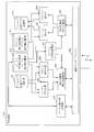
- FIG. 1 is a schematic diagram of an encryption system 1 to which a communication method according to Embodiment 1 can be applied.
- An outline of the operation when the key sharing apparatus C104 and the key sharing apparatus D105 share the Vernam encryption key via the network 101 or the network 106 not physically or logically connected to the network 101 is shown.
- Figure. The figure which shows the operation
- the flowchart which shows the flow of the communication processing of FIG. The figure which shows the operation
- the flowchart which shows the flow of the communication processing of FIG. FIG. 3 is a functional block diagram illustrating functional configurations of a terminal device A102 and a terminal device B103 in the first embodiment.
- FIG. 3 is a functional block diagram showing a functional configuration of a key sharing apparatus C104 and a key sharing apparatus D105 in the first embodiment.
- summary in case the key sharing apparatus C104 and the key sharing apparatus D105 share the Vernam encryption key 1201 and the block encryption key 1202 via the network 101 or the network 106.
- summary in case the terminal device A102 acquires the Vernam encryption key 1301 and the block encryption key 1302 via the communication cable 107 from the key sharing apparatus C104.
- FIG. 4 is a functional block diagram illustrating functional configurations of a terminal device A102 and a terminal device B103 in Embodiment 2.
- FIG. 9 is a functional block diagram illustrating functional configurations of a key sharing device C104 and a key sharing device D105 according to the second embodiment.
- the flowchart which shows the flow of the communication processing of FIG. The flowchart which shows the flow of the communication processing of FIG.
- FIG. 9 is a functional block diagram illustrating functional configurations of a terminal device A102 and a terminal device B103 according to Embodiment 3.
- the flowchart which shows the flow of the communication process of FIG. The flowchart which shows the flow of the communication process of FIG.
- FIG. 9 is a functional block showing functional configurations of terminal device A 102 and terminal device B 103 in Embodiment 4.
- FIG. 10 The figure which shows the operation
- the flowchart which shows the flow of the communication processing of FIG. FIG. 10 is a functional block diagram illustrating functional configurations of a terminal device A102 and a terminal device B103 in Embodiment 5.
- FIG. 23 is a functional block diagram illustrating functional configurations of a terminal device A102 and a terminal device B103 according to Embodiment 6.
- FIG. 20 is a diagram for explaining the processing of the Burnham encryption key increasing unit 819 in the seventh embodiment.
- FIG. 20 is a diagram for explaining processing of a Burnham encryption key increasing unit 819 in the eighth embodiment.
- FIG. 40 is a flowchart showing a flow of communication processing of FIG. 4 in the ninth embodiment.
- FIG. 40 is a flowchart showing a flow of communication processing of FIG. 4 in the ninth embodiment.
- Figure. 41 is a flowchart showing the communication process flow of FIG. 40.
- 10 is a flowchart showing a processing flow of a transmission control unit 803 of a terminal device 801 according to Embodiment 9.
- FIG. 10 is a flowchart showing a processing flow of a reception control unit 804 of a terminal device 801 according to Embodiment 9.
- FIG. 23 is a flowchart showing a communication process flow of FIG. 22 in the tenth embodiment.
- FIG. 23 is a flowchart showing a communication process flow of FIG. 22 in the tenth embodiment.
- FIG. 26 is a flowchart showing a flow of communication processing of FIG. 25 in the tenth embodiment.
- 18 is a flowchart showing a processing flow of a transmission control unit 803 of the terminal device 801 in the tenth embodiment.
- 18 is a flowchart showing a flow of processing of a reception control unit 804 of a terminal device 801 according to Embodiment 10.
- FIG. 10 is a flowchart showing a processing flow of a reception control unit 804 of a terminal device 801 according to Embodiment 9.
- FIG. 23 is a flowchart showing a communication process flow of FIG. 22 in the
- FIG. 29 is a flowchart showing a flow of communication processing of FIG. 28 in the eleventh embodiment.
- 18 is a flowchart showing a processing flow of a transmission control unit 803 of the terminal device 801 in the eleventh embodiment.
- 18 is a flowchart showing a processing flow of reception control section 804 of terminal apparatus 801 according to Embodiment 11. Explanatory drawing of operation
- FIG. FIG. 42 is a functional block diagram illustrating functional configurations of terminal device A 102 and terminal device B 103 according to Embodiment 13. The figure which shows an example of the hardware constitutions of the terminal device 801.
- the processing device is a CPU 911 or the like which will be described later.
- the storage device is a storage device such as a ROM 913, a RAM 914, or a magnetic disk 920, which will be described later. That is, the processing device and the storage device are hardware.
- Burnham cipher is used as an example of a one-time pad cipher.
- other one-time pad encryption may be used.
- Vernam cipher in the following description may be read as a one-time pad cipher.
- Embodiment 1 FIG.
- a technique for switching an encryption method from a Burnham cipher to a block cipher such as Camellia (registered trademark) or AES when an encryption key for a Burnham cipher (hereinafter referred to as a Burnham cipher key) is exhausted will be described.
- the encryption communication can be continued even during the period until the Vernam encryption key is replenished without causing the interruption of the encryption communication due to the shortage of the Burnham encryption key.
- different encryption methods are used according to the remaining amount (number of remaining bits) of the Vernam encryption key.
- the remaining amount of the Burnham encryption key is information that the device can easily grasp. Therefore, by switching the encryption method based on the remaining amount of the Burnham encryption key, it is possible to realize a mechanism for automatically switching the encryption method without requiring the user who uses the apparatus to perform an operation related to the switching of the encryption method.
- FIG. 1 is a schematic diagram of an encryption system 1 to which the communication method according to Embodiment 1 can be applied.
- a terminal device A102 and a terminal device B103 are connected to a network 101 such as the Internet.
- the key sharing apparatus C104 and the key sharing apparatus D105 are connected to the network 101 or the network 106 that is not physically or logically connected to the network 101.
- the terminal device A102 and the key sharing device C104 are connected by a communication cable 107 such as a USB (Universal Serial Bus).
- the terminal device B 103 and the key sharing device D 105 are connected by a communication cable 108.
- the terminal device A102 and the terminal device B103 are both a transmission side communication device (encryption device) that transmits encrypted data and a reception side communication device (decryption device) that receives the encrypted data.
- the terminal device A102 is an example of a transmission side communication device
- the terminal device B103 is an example of a reception side communication device.
- the terminal device A102 acquires the Vernam encryption key from the key sharing device C104
- the terminal device B103 acquires the Vernam encryption key from the key sharing device D105.
- FIG. 2 shows a case where a key sharing device C104 and a key sharing device D105 share a Vernam encryption key via the network 101 or the network 106 that is not physically or logically connected to the network 101. It is a figure which shows an operation
- the key sharing device C104 and the key sharing device D105 share the Vernam encryption key 201 via the network 101 or the network 106 by a predetermined method (key sharing algorithm). Note that any method may be used for sharing the Vernam encryption key 201.
- the key sharing device C104 and the key sharing device D105 may share the Vernam encryption key 201 after being connected via a physically or logically secure communication path.
- FIG. 3 is a diagram illustrating an operation outline when the terminal apparatus A 102 acquires the Vernam encryption key 301 from the key sharing apparatus C 104 via the communication cable 107.
- the terminal device A102 transmits a Vernam encryption key request message 302 to the key sharing device C104.
- the key sharing apparatus C104 transmits the owned Vernam encryption key 301 to the terminal apparatus A102.
- the terminal device A 102 that has received the Burnham encryption key 301 stores the Burnham encryption key 301 in the storage device.
- the terminal device B103 acquires the Vernam encryption key from the key sharing device D105 via the communication cable 108.
- FIG. 4 shows an outline of the operation when the terminal device A 102 and the terminal device B 103 start encryption communication using the Burnham cipher and the method is switched to encryption communication using the block cipher from the time when the encryption key for the Vernam cipher is insufficient.
- FIG. 4 shows an outline of the operation when the terminal device A 102 and the terminal device B 103 start encryption communication using the Burnham cipher and the method is switched to encryption communication using the block cipher from the time when the encryption key for the Burnham cipher is insufficient.
- the terminal device A102 has an encryption key 401 for Vernam encryption as advance preparation for encryption communication.
- the terminal device B103 also has a Vernam encryption key 402.
- the Burnham encryption key 401 held by the terminal device A102 and the Burnham encryption key 402 held by the terminal device B103 are respectively obtained from the key sharing device C104 and the key sharing device D105 by the method described above.
- the terminal device A 102 has a block cipher key 408 for block cipher.
- the terminal device B103 also has a block encryption key 410. It is assumed that the block encryption key 408 held by the terminal device A102 and the block encryption key 410 held by the terminal device B103 are the same.
- a method of sharing a block encryption key between the terminal device A 102 and the terminal device B 103 will be described in a later embodiment.
- the terminal device A 102 checks the remaining amount of the Vernam encryption key 401 that it holds.
- the Burnham encryption key 401 has a remaining amount. Therefore, the terminal device A102 calculates the amount of data communication that can be performed by the Burnham encryption based on the remaining amount of the Burnham encryption key 401.
- the terminal device A102 transmits a Vernam encryption communication request message 403 to the terminal device B103.
- the terminal device B 103 that has received the Vernam cipher communication request message 403 confirms the remaining amount of the Vernam cipher key 402 that it holds.
- the Burnham encryption key 402 has the same remaining amount as the Burnham encryption key 401.
- the terminal apparatus B 103 calculates the amount of data communication that can be performed by the Burnham encryption based on the remaining amount of the Burnham encryption key 402. Then, the terminal device B103 transmits a Vernam encryption communication approval message 404 to the terminal device A102.
- the terminal device A 102 that has received the Vernam cipher communication acknowledgment message 404 performs encryption using Vernam cipher on the communication data using the Vernam cipher key 401 to generate encrypted communication data 405.
- the terminal device A102 transmits the generated encrypted communication data 405 to the terminal device B103.
- the terminal device B 103 that has received the encrypted communication data 405 decrypts the encrypted communication data 405 with the Vernam encryption key 402 to obtain communication data. Since the Burnham encryption key 401 and the Burnham encryption key 402 are the same, the encrypted communication data 405 encrypted with the Burnham encryption key 401 can be decrypted with the Burnham encryption key 402.
- the terminal device A102 sends a block cipher switching request message 406 to the terminal device.
- the terminal device B103 receives the block cipher switching request message 406, the terminal device B103 transmits a block cipher switching approval message 407 to the terminal device A102.
- the terminal device A 102 that has received the block cipher switching approval message 407 encrypts the communication data with the block cipher key 408 and generates encrypted communication data 409. Then, the terminal device A102 transmits the generated encrypted communication data 409 to the terminal device B103.
- the terminal device B 103 that has received the encrypted communication data 409 decrypts the encrypted communication data 409 with the block encryption key 410 to obtain communication data. Since the block encryption key 408 and the block encryption key 410 are the same, the encrypted communication data 409 encrypted with the block encryption key 408 can be decrypted with the block encryption key 410.
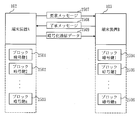
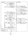
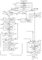
- FIG. 5 is a flowchart showing the flow of the communication process of FIG.
- the terminal device A102 checks the amount (number of bits) of the Vernam encryption key 401 that it holds, and calculates the amount of data that can be encrypted using the Vernam encryption (S101). Then, the terminal apparatus A102 transmits a Vernam encryption communication request message 403 to the terminal apparatus B103 (S102). The terminal device B103 receives the Vernam encryption communication request message 403 from the terminal device A102 (S103). Then, the terminal device B103 confirms the amount of the Vernam encryption key 402 that it holds, and calculates the amount of data that can be encrypted using the Vernam encryption (S104). Then, the terminal device B103 transmits a Vernam encryption communication approval message 404 to the terminal device A102 (S105).
- the terminal device A102 receives the Vernam encryption communication approval message 404 from the terminal device B103 (S106). Then, the terminal device A 102 encrypts data for the unit data amount in the communication data with the Vernam encryption key 401 and generates encrypted communication data 405. (S107).
- the data for the unit data amount is data having a predetermined number of bits. Alternatively, it is data in a predetermined unit, for example, data of one file. For example, in the case of voice call data in a mobile phone, the voice call data is as short as about 10 to 20 milliseconds.
- the terminal device A102 transmits the encrypted communication data 405 to the terminal device B103 (S108).
- the terminal device B103 receives the encrypted communication data 405 from the terminal device A102 (S109). Then, the terminal device B103 decrypts the encrypted communication data 405 with the Vernam encryption key 402 and obtains communication data (S110).
- the terminal device A102 checks whether there is untransmitted communication data (S111). If there is no untransmitted communication data (NO in S111), the terminal device A102 ends the process (S112). On the other hand, if there is untransmitted communication data (YES in S111), the terminal device A102 advances the process to S113.
- the terminal device A102 confirms whether the amount of data that can be encrypted using Vernam encryption is equal to or greater than the unit data amount to be encrypted at one time (S113). At this time, the terminal device A102 subtracts the data amount of the communication data that has been transmitted to the terminal device B103 so far from the data amount that can be encrypted with the Vernam encryption calculated in S101. The amount of data that can be encrypted using Vernam encryption at this time is calculated. If the amount of data that can be encrypted using the Burnham encryption is equal to or greater than the unit data amount (YES in S113), the terminal device A102 returns the process to S107. On the other hand, if the amount of data that can be encrypted using Vernam encryption is less than the unit data amount (NO in S113), the terminal device A102 transmits a block cipher switching request message 406 to the terminal device B103 (S114).
- the terminal device B103 receives the block cipher switching request message 406. (S115). Then, the terminal apparatus B103 transmits a block cipher switching approval message 407 to the terminal apparatus A102 (S116). The terminal device A102 receives the block cipher switching approval message 407 (S117). Then, the terminal device A102 encrypts data for the unit data amount in the communication data with the block encryption key 408, and generates encrypted communication data 409 (S118). Then, the terminal device A102 transmits the encrypted communication data 409 to the terminal device B103 (S119). The terminal device B103 receives the encrypted communication data 409 (S120). Then, the terminal device B103 decrypts the encrypted communication data 409 with the block encryption key 410, and obtains communication data (S121).
- the terminal device A102 checks whether there is untransmitted communication data (S122). If there is no untransmitted communication data (NO in S122), the terminal device A102 ends the process (S123). On the other hand, if there is untransmitted communication data (YES in S122), terminal device A102 returns the process to S118.
- FIG. 6 is a diagram showing an outline of the operation when the cipher communication using the block cipher is started because the Vernam cipher key is insufficient when the terminal device A 102 and the terminal device B 103 start the cipher communication.
- the terminal device A102 has a block cipher key 603 for block cipher.
- the terminal device B103 also has a block encryption key 605. It is assumed that the block encryption key 603 held by the terminal device A102 and the block encryption key 605 held by the terminal device B103 are the same.
- a method of sharing a block encryption key between the terminal device A 102 and the terminal device B 103 will be described in a later embodiment.
- the terminal device A102 confirms the amount of the Vernam encryption key that it holds. Here, it is assumed that the Vernam encryption key is depleted (0 bits). Therefore, the terminal device A102 transmits a block cipher communication request message 601 to the terminal device B103.
- the terminal device B103 that has received the block cipher communication request message 601 transmits a block cipher communication approval message 602 to the terminal device A102.
- Receiving the block cipher communication approval message 602 the terminal device A 102 encrypts the communication data using the block cipher using the block cipher key 603, and generates encrypted communication data 604. Then, the terminal device A102 transmits the generated encrypted communication data 604 to the terminal device B103.
- the terminal apparatus B 103 that has received the encrypted communication data 604 decrypts the encrypted communication data 604 with the block encryption key 605 to obtain communication data. Since the block encryption key 603 and the block encryption key 605 are the same, the encrypted communication data 604 encrypted with the block encryption key 603 can be decrypted with the block encryption key 605.
- FIG. 7 is a flowchart showing the flow of the communication process of FIG.
- the terminal device A102 confirms the amount of the Burnham encryption key that is held, and grasps that the Burnham encryption key is insufficient (S201). When the amount of data that can be encrypted using the Burnham encryption is less than the unit data amount that is encrypted at a time, it is determined that the Burnham encryption key is insufficient. Then, the terminal device A102 transmits a block cipher communication request message 601 to the terminal device B103 (S202). The terminal device B103 receives the block cipher communication request message 601 from the terminal device A102 (S203). Then, the terminal device B103 transmits a block cipher communication approval message 602 to the terminal device A102 (S204).
- the terminal device A102 receives the block cipher communication approval message 602 from the terminal device B103 (S205). Then, the terminal device A102 encrypts the data for the unit data amount in the communication data with the block encryption key 603, and generates the encrypted communication data 604 (S206). Then, the terminal device A102 transmits the encrypted communication data 604 to the terminal device B103 (S207). The terminal device B103 receives the encrypted communication data 604 (S208). Then, the terminal device B103 decrypts the encrypted communication data 604 with the block encryption key 605 and obtains communication data (S209).
- the terminal device A102 confirms whether there is untransmitted communication data (S210). If there is no untransmitted communication data (NO in S210), the terminal device A102 ends the process (S211). On the other hand, if there is untransmitted communication data (YES in S210), the terminal device A102 returns the process to S206.
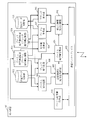
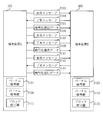
- FIG. 8 is a functional block diagram illustrating functional configurations of the terminal device A 102 and the terminal device B 103 according to the first embodiment.
- the terminal device A102 and the terminal device B103 have the same functional configuration. Therefore, here, the terminal device A102 and the terminal device B103 will be described as the terminal device 801.
- the terminal device 801 includes a communication interface 802, a transmission control unit 803 (encryption control unit), a reception control unit 804 (decryption control unit), a Vernam encryption key management unit 805, a Vernam encryption unit 806, a Vernum decryption unit 807, a block cipher Unit 808, block decryption unit 809, Burnham encryption key acquisition unit 810, transmission data storage unit 811, reception data storage unit 812, Vernam encryption key storage unit 813 (Vernum decryption key storage unit), and block encryption key storage unit 814 (block) A decryption key storage unit).
- the communication interface 802 is a communication device that communicates with an external device. More specifically, the communication interface 802 is a device for receiving a Vernam encryption key from the key sharing device C104 or the key sharing device D105. In addition, the communication interface 802 transmits encrypted communication data to a terminal device serving as a reception side when the terminal device 801 is a transmission side of encrypted communication, and a transmission side when the terminal device 801 is a reception side of the communication interface 802 encryption communication. Is a device for receiving encrypted communication data from a terminal device.
- the transmission control unit 803 refers to the remaining amount information of the Burnham encryption key obtained from the Burnham encryption key management unit 805, and determines which of the Burnham encryption unit 806 and the block encryption unit 808 encrypts the communication data. It is controlled by the processing device. Further, the transmission control unit 803 causes the Vernam encryption unit 806 or the block encryption unit 808 to perform encryption, and transmits the obtained encrypted communication data.
- the reception control unit 804 receives encrypted communication data. Then, the reception control unit 804 refers to the remaining amount information of the Burnham key obtained from the Burnham encryption key management unit 805 to decrypt the received encrypted communication data to either the Burnham decryption unit 807 or the block decryption unit 809.
- the processor controls whether to decrypt.
- the Burnham encryption key management unit 805 provides information related to the remaining amount of the Burnham encryption key stored in the Burnham encryption key storage unit 813 to the transmission control unit 803 and the reception control unit 804. More specifically, the Burnham encryption key management unit 805 provides information indicating whether or not the remaining amount of the Burnham encryption key is insufficient. The Burnham encryption key management unit 805 determines that the Burnham encryption key is insufficient when the amount of data that can be encrypted using the Burnham encryption is less than the unit data amount to be encrypted at a time. .
- the Burnham encryption unit 806 acquires communication data from the transmission data storage unit 811 and acquires a Burnham encryption key from the Burnham encryption key storage unit 813. Then, the Burnham encryption unit 806 applies the Burnham encryption using the Burnham encryption key to the communication data by the processing device, and generates encrypted communication data. The obtained encrypted communication data is passed to the transmission control unit 803.
- the Burnham decryption unit 807 acquires the Vernam encryption key from the Vernam encryption key storage unit 813 and acquires the encrypted communication data from the reception control unit 804. Then, the Burnham decryption unit 807 decrypts the encrypted communication data using the Vernam encryption key by the processing device, and generates communication data. The obtained communication data is stored in the reception data storage unit 812.
- the block encryption unit 808 acquires communication data from the transmission data storage unit 811 and acquires a block encryption key from the block encryption key storage unit 814. Then, the block encryption unit 808 performs block encryption using the block encryption key on the communication data by the processing device, and generates encrypted communication data. The obtained encrypted communication data is passed to the transmission control unit 803.
- the block decryption unit 809 obtains a block encryption key from the block encryption key storage unit 814 and obtains encrypted communication data from the reception control unit 804. Then, the block decryption unit 809 decrypts the encrypted communication data using the block encryption key by the processing device, and generates communication data. The obtained communication data is stored in the reception data storage unit 812.
- the Burnham encryption key acquisition unit 810 acquires a Burnham encryption key from a key sharing device such as the key sharing device C104 or the key sharing device D105, and stores the obtained Burnham encryption key in the Burnham encryption key storage unit 813.
- the transmission data storage unit 811 is a storage device that stores communication data to be transmitted to the terminal device on the receiving side.
- the received data storage unit 812 is a storage device that stores communication data acquired from a terminal device on the transmission side.
- the Burnham encryption key storage unit 813 is a storage device that stores a Burnham encryption key.
- the block encryption key storage unit 814 is a storage device that stores a block encryption key.
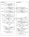
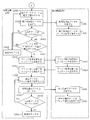
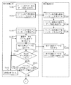
- FIG. 9 is a flowchart illustrating a process flow of the transmission control unit 803 of the terminal device 801.
- the transmission control unit 803 acquires remaining amount information indicating whether or not the remaining amount of the Burnham encryption key is insufficient from the Burnham encryption key management unit 805 (S301). If the remaining amount of the Vernam encryption key is not insufficient (NO in S302), the transmission control unit 803 advances the process to S303, and if the remaining amount is insufficient (YES in S302), the transmission control unit 803 performs the process in S311. Advance (S302).
- the transmission control unit 803 transmits a Vernam cipher communication request message to the terminal device B 103 via the communication interface 802 (S303), and receives the Vernam cipher communication approval message from the terminal device B103 (S304). Then, the transmission control unit 803 causes the Vernam encryption unit 806 to encrypt the data corresponding to the unit data amount in the communication data, and acquires the encrypted communication data (S305). The transmission control unit 803 transmits the acquired encrypted communication data to the terminal device B 103 via the communication interface 802 (S306).
- the transmission control unit 803 confirms whether there is untransmitted communication data (S307). If there is no untransmitted communication data (NO in S307), the transmission control unit 803 ends the process. On the other hand, if there is untransmitted communication data (YES in S307), the transmission control unit 803 advances the process to S308.
- the transmission control unit 803 obtains remaining amount information indicating whether or not the remaining amount of the Burnham encryption key is insufficient from the Burnham encryption key management unit 805, and determines whether or not encryption communication using the Burnham encryption can be continued. Determination is made (S308). If it can be continued (YES in S308), the transmission control unit 803 returns the process to S305. On the other hand, if it cannot be continued (NO in S308), the transmission control unit 803 advances the process to S309.
- the transmission control unit 803 transmits a block cipher switching request message to the terminal device B 103 via the communication interface 802 (S309), receives a block cipher switching approval message from the terminal device B 103 (S310), and proceeds to S313. .
- the transmission control unit 803 transmits a block cipher communication request message to the terminal device B 103 (S311), receives a block cipher communication approval message from the terminal device B 103 (S312), and advances the process to S313.
- the transmission control unit 803 causes the block encryption unit 808 to encrypt the data corresponding to the unit data amount in the communication data, and acquires the encrypted communication data (S313). Then, the transmission control unit 803 transmits the encrypted communication data to the terminal device B103 (S314). Subsequently, the transmission control unit 803 checks whether there is untransmitted communication data (S315). If there is no untransmitted communication data (NO in S315), the transmission control unit 803 ends the process. On the other hand, if there is untransmitted communication data (YES in S315), the transmission control unit 803 returns the process to S313.
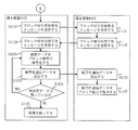
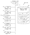
- FIG. 10 is a flowchart illustrating a processing flow of the reception control unit 804 of the terminal device 801.
- the reception control unit 804 receives the Vernam encryption communication request message or the block encryption communication request message from the terminal device A102 via the communication interface 802 (S401). The reception control unit 804 advances the process to S403 when receiving the Vernam encryption request message, and advances the process to S410 when receiving the block encryption request message (S402).
- the reception control unit 804 transmits a Vernam encryption acknowledgment message to the terminal device A102 via the communication interface 802 (S403), and receives encrypted communication data from the terminal device A102 (S404).
- the reception control unit 804 transmits the received encrypted communication data to the Burnham decryption unit 807 to decrypt and generate communication data (S405).
- the generated communication data is stored in the reception data storage unit 812.
- reception control unit 804 confirms the presence / absence of unreceived communication data (S406). If there is no unreceived communication data (NO in S406), the reception control unit 804 ends the process. On the other hand, if there is unreceived communication data (YES in S406), reception control unit 804 advances the process to S407. Whether there is unreceived communication data is determined, for example, based on whether the next encrypted data or the block cipher switching request message is transmitted within a predetermined time.
- the reception control unit 804 obtains remaining amount information indicating whether or not the remaining amount of the Burnham encryption key is insufficient from the Burnham encryption key management unit 805, and determines whether or not encryption communication using the Burnham encryption can be continued. Determination is made (S407). If it can be continued (YES in S407), the reception control unit 804 returns the process to S404. On the other hand, if it cannot be continued (NO in S407), the reception control unit 804 advances the process to S408.
- the reception control unit 804 receives the block cipher switching request message from the terminal device A102 (S408), transmits a block cipher switching approval message to the terminal device A102 (S409), and advances the process to S411.
- the reception control unit 804 transmits a block cipher communication approval message to the terminal device A102 (S410), and proceeds to S411.
- the reception control unit 804 receives the encrypted communication data from the terminal device A102 (S411).
- the reception control unit 804 transmits the received encrypted communication data to the block decryption unit 809 to decrypt and generate communication data (S412).
- the generated communication data is stored in the reception data storage unit 812.
- the reception control unit 804 confirms whether there is untransmitted communication data (S413). If there is no untransmitted communication data (NO in S413), the reception control unit 804 ends the process. On the other hand, if there is untransmitted communication data (YES in S413), the reception control unit 804 returns the process to S411.
- the reception control unit 804 determines whether or not the encrypted communication using the Burnham encryption can be continued, and determines whether to continue the encrypted communication using the Burnham encryption or to switch to the encrypted communication using the block encryption. did. However, the reception control unit 804 does not determine whether or not the encryption communication using the Burnham encryption can be continued, and continues the encryption communication using the Burnham encryption depending on whether or not the block encryption switching request message is received from the terminal device A102. Alternatively, it may be determined whether to switch to block cipher encryption communication.
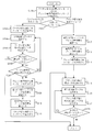
- FIG. 11 is a functional block diagram showing a functional configuration of the key sharing apparatus C104 and the key sharing apparatus D105 in the first embodiment.
- the key sharing device C104 and the key sharing device D105 have the same functional configuration. Therefore, here, the key sharing device C104 and the key sharing device D105 will be described as the key sharing device 1101.
- the key sharing device 1101 includes a communication interface 1102, a Burnham encryption key sharing unit 1103, a Burnham encryption key transfer unit 1104, and a Burnham encryption key storage unit 1105.
- the communication interface 1102 is a communication device that communicates with an external device. More specifically, the communication interface 1102 is a device for performing communication for sharing a Burnham encryption key with another key sharing device. Further, it is a device for transmitting a Vernam encryption key to a terminal device connected by a communication cable or the like.
- the Burnham encryption key sharing unit 1103 communicates with another key sharing device, shares the Burnham encryption key, and stores the shared Burnham encryption key in the Burnham encryption key storage unit 1105.
- the Vernam encryption key transfer unit 1104 acquires the Vernam encryption key from the Vernam encryption key storage unit 1105 and transmits it to the terminal device.
- the Burnham encryption key storage unit 1105 is a storage device that stores a Burnham encryption key obtained by communication with another key sharing device.
- the encryption system 1 detects a shortage of the Burnham encryption key in the encrypted communication using the Burnham encryption performed between the two parties. Thereby, even when the Vernam encryption key is insufficient during the encryption communication or at the start of the encryption communication, it is possible to switch from the encryption communication using the Vernam encryption to the encryption communication using the block encryption and continue the encryption communication.
- switching from encryption communication using Vernam encryption to encryption communication using block encryption is performed when the Burnham encryption key is insufficient. Since the shortage of the Burnham encryption key can be detected in the apparatus, it is possible to realize switching of encryption communication without requiring the judgment and processing of the user of the terminal apparatus A102 and terminal apparatus B103.
- the terminal device A102 or the terminal device B103 obtains a Vernam encryption key from the key sharing device C104 or the key sharing device D105, and the remaining number of bits of the Vernam encryption key is determined again. It is conceivable that the number of bits will be greater than. In this case, the terminal device A 102 and the terminal device B 103 may switch from encrypted communication using block cipher to encrypted communication using Vernam encryption.
- Embodiment 2 a block encryption key sharing method will be described.
- the terminal device A 102 and the terminal device B 103 acquire the Vernam encryption key from the key sharing device C 104 and the key sharing device D 105 in the first embodiment, the block encryption key is also acquired at the same time. Thereby, the block encryption key is also safely shared between the terminal devices.
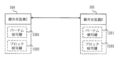
- FIG. 12 is a diagram showing an operation outline when the key sharing apparatus C104 and the key sharing apparatus D105 share the Vernam encryption key 1201 and the block encryption key 1202 via the network 101 or the network 106.
- the key sharing device C104 and the key sharing device D105 share the Vernam encryption key 1201 and the block encryption key 1202 via the network 101 or the network 106 by a predetermined method (key sharing algorithm). Note that any method may be used for sharing the Vernam encryption key 1201 and the block encryption key 1202.
- the key sharing device C104 and the key sharing device D105 may be connected to each other via a physically or logically secure communication path and share the Vernam encryption key 1201 and the block encryption key 1202.
- the key sharing device C104 and the key sharing device D105 may be connected to each other via a physically or logically secure communication path and share the Vernam encryption key 1201 and the block encryption key 1202.
- FIG. 13 is a diagram illustrating an outline of operation when the terminal device A 102 acquires the Vernam encryption key 1301 and the block encryption key 1302 from the key sharing apparatus C 104 via the communication cable 107.
- the terminal device A102 transmits an encryption key request message 1303 to the key sharing device C104.
- the key sharing apparatus C104 transmits the stored Vernam encryption key 1301 and the block encryption key 1302 to the terminal apparatus A102.
- the terminal device A 102 that has received the Vernam encryption key 1301 and the block encryption key 1302 stores the Vernam encryption key 1301 and the block encryption key 1302.
- the terminal apparatus B103 acquires the Vernam encryption key and the block encryption key from the key sharing apparatus D105 via the communication cable 108.
- FIG. 14 is a functional block diagram illustrating functional configurations of the terminal device A 102 and the terminal device B 103 according to the second embodiment.
- the terminal device shown in FIG. 14 includes a block encryption key acquisition unit 815 in addition to the functions provided in the terminal device shown in FIG.
- the block encryption key acquisition unit 815 acquires a block encryption key from a key sharing device such as the key sharing device C104 or the key sharing device D105, and stores the obtained block encryption key in the block encryption key storage unit 814.
- FIG. 15 is a functional block diagram illustrating functional configurations of the key sharing device C104 and the key sharing device D105 according to the second embodiment.
- the key sharing apparatus shown in FIG. 15 includes a block encryption key sharing unit 1106, a block encryption key transfer unit 1107, and a block encryption key storage unit 1108 in addition to the functions provided in the key sharing apparatus shown in FIG.
- the block encryption key sharing unit 1106 communicates with other key sharing devices, shares the block encryption key, and stores the shared block encryption key in the block encryption key storage unit 1108.
- the block encryption key transfer unit 1107 acquires the block encryption key from the block encryption key storage unit 1108 and transmits it to the terminal device.
- the block encryption key storage unit 1108 is a storage device that stores a block encryption key obtained by communication with another key sharing device.
- the key sharing device C104 and the key sharing device D105 share the block encryption key together with the Burnham encryption key. Then, the terminal device A102 and the terminal device B103 obtain the block cipher key together with the Vernam cipher key from each of the key sharing device C104 and the key sharing device D105. Thereby, the block encryption key is also safely shared between the terminal devices.
- Embodiment 3 generation of a block encryption key from a remaining Burnham encryption key when the remaining amount of the Burnham encryption key becomes smaller than a predetermined amount will be described.
- the terminal device A102 and the terminal device B103 share only the Vernam encryption key at the start of encryption communication and do not hold the block encryption key. In the following description, it is assumed that there is still an amount necessary for generating the block encryption key when the Vernam encryption key is insufficient.
- FIG. 16 shows an outline of the operation when the terminal device A102 and the terminal device B103 start encryption communication using the Burnham cipher and the method is switched to encryption communication using the block cipher from the time when the encryption key for the Burnham cipher is insufficient.
- FIG. 16 in addition to the process of FIG. 4 in the first embodiment, a process of generating a block encryption key from a Vernam encryption key is performed.
- the terminal device A102 has a Vernam encryption key 1601 for Vernam encryption.
- the terminal device B103 also has a Vernam encryption key 1602.
- the Vernam encryption key 1601 held by the terminal device A102 and the Vernam encryption key 1602 held by the terminal device B103 are obtained from the key sharing device C104 and the key sharing device D105, respectively, by the method described above.
- the terminal device A 102 and the terminal device B 103 do not have the block encryption key 1608 and the block encryption key 1610, respectively.
- the processing from the start of processing until the terminal device B 103 transmits the block cipher switching approval message 1607 to the terminal device A 102 is the same as the processing shown in FIG.
- the terminal device A 102 that has received the block cipher switching approval message 1607 generates a block cipher key 1608 from the remaining Vernam cipher key 1601.
- the terminal device A 102 encrypts the communication data with the block encryption key 1608 and generates encrypted communication data 1609.
- the terminal device A102 transmits the generated encrypted communication data 1609 to the terminal device B103.
- the terminal device B 103 that has received the encrypted communication data 1609 generates a block encryption key 1610 from the remaining Vernam encryption key 1602.
- the terminal device B103 decrypts the encrypted communication data 1609 with the block encryption key 1610, and obtains communication data.
- the terminal device A 102 and the terminal device B 103 generate a block encryption key from a Vernam encryption key by the same method shared in advance.
- the terminal device A 102 and the terminal device B 103 use a part of the remaining Vernam encryption key as it is as a block encryption key. That is, when the block encryption key is 256 bits, predetermined 256 bits are extracted from the remaining Vernam encryption key and used as the block encryption key.
- 17 and 18 are flowcharts showing the flow of the communication process of FIG. In the process shown in FIGS. 17 and 18, in addition to the process shown in FIG. 5 in the first embodiment, a process for generating a block encryption key from a Vernam encryption key is performed.
- the terminal device A102 Upon receiving the block cipher switching approval message 407, the terminal device A102 generates a block cipher key 1608 from the remaining Vernam cipher key 1601 (S518). The terminal device A102 encrypts data for the unit data amount in the communication data with the block encryption key 1608, and generates encrypted communication data 1609 (S519). Then, the terminal device A102 transmits the encrypted communication data 1609 to the terminal device B103 (S520). The terminal apparatus B103 receives the encrypted communication data 1609 (S521). Then, the terminal device B103 generates a block encryption key 1610 from the remaining Vernam encryption key 1602 (S522). Then, the terminal device B103 decrypts the encrypted communication data 1609 with the block encryption key 1610, and obtains communication data (S523).
- the processing from S524 to S525 is the same as the processing from S122 to S123 shown in FIG.
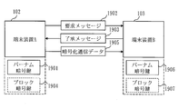
- FIG. 19 is a diagram showing an outline of the operation when the cipher communication using the block cipher is started because the Vernam cipher key is insufficient when the terminal device A 102 and the terminal device B 103 start the cipher communication.
- a process of generating a block encryption key from a Vernam encryption key is performed.
- the Vernam encryption key is not depleted at the start of communication, and the amount necessary for generating the block encryption key remains.
- the processing from the start of processing until the terminal device B 103 transmits the block cipher switching approval message 1903 to the terminal device A 102 is the same as the processing shown in FIG.
- the terminal device A 102 that has received the block cipher communication acknowledgment message 1903 generates a block cipher key 1904 from the remaining Vernam cipher key 1901.
- the terminal device A 102 encrypts the communication data with the block encryption key 1904 and generates encrypted communication data 1905.
- the terminal device A102 transmits the generated encrypted communication data 1905 to the terminal device B103.
- the terminal device B 103 that has received the encrypted communication data 1905 generates a block encryption key 1907 from the remaining Vernam encryption key 1906.
- the terminal device B103 decrypts the encrypted communication data 1905 with the block encryption key 1907 to obtain communication data.
- FIG. 20 is a flowchart showing the flow of the communication process of FIG.
- a process for generating a block cipher key from a Vernam cipher key is performed.
- the terminal device A102 Upon receiving the block cipher communication approval message 1903, the terminal device A102 generates a block cipher key 1904 from the remaining Vernam cipher key 1901 (S606). The terminal device A102 encrypts data for the unit data amount in the communication data with the block encryption key 1904, and generates encrypted communication data 1905 (S607). Then, the terminal device A102 transmits the encrypted communication data 1905 to the terminal device B103 (S608). The terminal device B103 receives the encrypted communication data 1905 (S609). Then, the terminal device B103 generates a block encryption key 1907 from the remaining Vernam encryption key 1906 (S610). Then, the terminal device B103 decrypts the encrypted communication data 1905 with the block encryption key 1907 to obtain communication data (S611).
- FIG. 21 is a functional block diagram illustrating functional configurations of the terminal device A 102 and the terminal device B 103 according to the third embodiment.
- the terminal device shown in FIG. 21 includes an encryption key conversion unit 816 in addition to the functions provided in the terminal device shown in FIG.
- the encryption key conversion unit 816 acquires a Vernam encryption key from the Vernam encryption key storage unit 813, generates a block encryption key from the acquired Burnham encryption key by a processing device, and stores the block encryption key in the block encryption key storage unit 814.
- the encryption system 1 according to Embodiment 3 generates a block encryption key from the remaining Vernam encryption key. Thereby, it is possible to switch from encryption communication using the Vernam encryption key to encryption communication using the block encryption without sharing the block encryption key in advance as in the second embodiment.
- a block encryption key is generated from the remaining Burnham encryption key.
- the Vernam encryption key remains more than the amount necessary for generating the block encryption key. Therefore, a block cipher key may be generated from the remaining Vernam cipher key before the Vernam cipher key is insufficient.
- the block cipher key may be generated from the remaining Vernam cipher key when the terminal device acquires the Vernam cipher key from the key sharing apparatus. In this case, there is no case where the Vernam encryption key remains more than the amount necessary to generate the block encryption key, and the block encryption key cannot be generated from the remaining Burnham encryption key.
- Embodiment 4 FIG.
- a case will be described in which a plurality of block encryption keys are held, the block encryption key used for encryption communication is periodically discarded, and encryption communication is performed using a new block encryption key.
- the encryption communication by block cipher is implement
- the above-described function is added to the first embodiment as an example.
- FIG. 22 shows an outline of the operation when the terminal device A 102 and the terminal device B 103 start encryption communication using the Burnham cipher and the method is switched to encryption communication using the block cipher from the time when the encryption key for the Burnham cipher is insufficient.
- FIG. 22 in addition to the process of FIG. 4 in the first embodiment, a process of discarding the used block encryption key and setting the next block encryption key is performed.
- the terminal device A102 has a Vernam encryption key 2201 for Vernam encryption and a plurality of block encryption keys 2202 to 2204 (block encryption keys 1 to n).
- the terminal device B103 also has a Vernam encryption key 2205 and a plurality of block encryption keys 2206 to 2208 (block encryption keys 1 to n).
- the Burnham encryption key 2201 and the Burnham encryption key 2205 are the same, and the block encryption keys 2202 to 2204 and the block encryption keys 2206 to 2208 are also the same.
- the values 1 to n of the block encryption key are identification numbers (identification information) for identifying the block encryption key.
- the processing from the start of processing until the terminal device B 103 transmits the block cipher switching approval message 2213 to the terminal device A 102 is the same as the processing shown in FIG.
- the terminal device A102 encrypts the communication data with the block cipher key 2202, generates encrypted communication data 2214, and transmits it to the terminal device B103.
- the terminal apparatus B 103 that has received the encrypted communication data 2214 decrypts the encrypted communication data 2214 with the block encryption key 2206 to obtain communication data.
- the terminal device A102 and the terminal device B103 discard the block encryption key 2202 and the block encryption key 2206, respectively.
- the terminal device A 102 and the terminal device B 103 are set to use the block encryption key 2203 and the block encryption key 2207, respectively, when performing encryption with the block encryption key next time.
- FIGS. 23 and 24 are flowcharts showing the flow of the communication process of FIG. In the processing shown in FIGS. 23 and 24, in addition to the processing shown in FIG. 5 in the first embodiment, processing for discarding the used block encryption key and setting the next block encryption key is performed.
- the processing from S701 to S717 is the same as the processing from S101 to S117 shown in FIG.
- the terminal device A 102 When the terminal device A 102 receives the block cipher switching approval message 2213, the terminal device A 102 encrypts data corresponding to the unit data amount of the communication data with the block cipher key 2202, and generates encrypted communication data 2214 (S718). Then, the terminal device A102 transmits the encrypted communication data 2214 to the terminal device B103 (S719). The terminal device B103 receives the encrypted communication data 2214 (S720). Then, the terminal device B103 decrypts the encrypted communication data 2214 with the block encryption key 2206 to obtain communication data (S721).
- the terminal device A102 checks whether there is untransmitted communication data (S722). If there is no untransmitted communication data (NO in S722), the terminal apparatus A102 discards the block encryption key 2202, and when performing encryption using the block encryption key next, the terminal device A102 is set to use the block encryption key 2203. (S723). Then, the terminal device A102 ends the process (S724). On the other hand, if there is untransmitted communication data (YES in S722), the terminal apparatus A102 returns the process to S718. Similarly, the terminal apparatus B103 confirms the presence / absence of unreceived communication data (S725).
- the terminal device B103 determines that there is no unreceived communication data. If there is no unreceived communication data (NO in S725), the terminal device A102 discards the block encryption key 2206, and then sets to use the block encryption key 2207 when performing encryption using the block encryption key. (S726). Then, the terminal device B103 ends the process (S727). On the other hand, if there is unreceived communication data (YES in S725), the terminal apparatus B103 returns the process to S720.
- FIG. 25 is a diagram illustrating an outline of an operation when the cipher communication using the block cipher is started because the Vernam cipher key is insufficient when the terminal device A 102 and the terminal device B 103 start the cipher communication.
- a process of discarding the used block encryption key and setting the next block encryption key is performed.
- the terminal device A102 has a plurality of block encryption keys 2501 to 2503 (block encryption keys 1 to n).
- the terminal device B103 also has a plurality of block encryption keys 2504 to 2506 (block encryption keys 1 to n). It is assumed that the block encryption keys 2501 to 2503 held by the terminal device A102 and the block encryption keys 2504 to 2506 held by the terminal device B103 are the same.
- the processing from the start of processing until the terminal device B 103 transmits the block cipher switching approval message 2508 to the terminal device A 102 is the same as the processing shown in FIG.
- the terminal apparatus B103 decrypts the encrypted communication data 2509 with the block encryption key 2504 to obtain communication data.
- the terminal device A102 and the terminal device B103 discard the block encryption key 2501 and the block encryption key 2504, respectively, and then perform encryption using the block encryption key, respectively, the block encryption key 2502, Setting is made so that the block encryption key 2505 is used.
- the terminal device A102 and the terminal device B103 discard the block encryption key 2501 and the block encryption key 2504, respectively.
- the terminal device A102 and the terminal device B103 are set to use the block encryption key 2502 and the block encryption key 2505, respectively, when performing encryption with the block encryption key next time.
- FIG. 26 is a flowchart showing the flow of the communication process of FIG. In the process shown in FIG. 26, in addition to the process shown in FIG. 7 in the first embodiment, a process of discarding the used block encryption key and setting the next block encryption key is performed.
- the processing from S801 to S805 is the same as the processing from S201 to S205 shown in FIG.
- the terminal device A102 Upon receiving the block cipher communication approval message 2508 from the terminal device B 103, the terminal device A102 encrypts the unit data amount of the communication data with the block cipher key 2501, and generates encrypted communication data 2509 (S806). . Then, the terminal device A102 transmits the encrypted communication data 2509 to the terminal device B103 (S807). The terminal apparatus B103 receives the encrypted communication data 2509 (S808). Then, the terminal apparatus B103 decrypts the encrypted communication data 2509 with the block encryption key 2504, and obtains communication data (S809).
- the terminal device A102 confirms whether there is untransmitted communication data (S810). If there is no untransmitted communication data (NO in S810), the terminal device A102 discards the block encryption key 2501, and when performing encryption using the block encryption key next, the terminal device A102 is set to use the block encryption key 2502. (S811). Then, the terminal device A102 ends the process (S812). On the other hand, if there is untransmitted communication data (YES in S810), the terminal apparatus A102 returns the process to S806. Similarly, the terminal apparatus B103 confirms whether there is unreceived communication data (S813).
- the terminal device B103 determines that there is no unreceived communication data. If there is no unreceived communication data (NO in S813), the terminal apparatus B103 discards the block encryption key 2504, and then sets to use the block encryption key 2505 when performing encryption using the block encryption key. (S814). Then, the terminal device B103 ends the process (S815). On the other hand, if there is unreceived communication data (YES in S813), the terminal apparatus A102 returns the process to S808.
- FIG. 27 is a functional block diagram illustrating functional configurations of the terminal device A 102 and the terminal device B 103 according to the fourth embodiment.
- the terminal device shown in FIG. 27 includes a block encryption key update unit 817 in addition to the functions provided in the terminal device shown in FIG.
- the block encryption key update unit 817 deletes the block encryption key currently used from the block encryption key storage unit 814 and sets the next block encryption key.
- a plurality of block encryption keys are held, the block encryption keys used for encrypted communication are periodically discarded, and new block encryption keys are used. To perform encrypted communication. Thereby, the safety
- the encryption key conversion unit 816 (see FIG. 21) generates a plurality of block encryption keys from the Vernam encryption key.
- the remaining Vernam encryption key is divided into predetermined block bits to be a plurality of block encryption keys. That is, when the block encryption key is 256 bits, the remaining Vernam encryption key (a part thereof) is divided into 256 bits to form a plurality of block encryption keys.
- Embodiment 5 in the case where the encryption with the block cipher is performed when the remaining block cipher key is one in the fourth embodiment, the current block cipher key is updated by randomizing a hash function or the like. Will be described. Thus, a technique for preventing a decrease in security due to repeated use of the same block encryption key will be described.
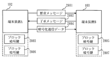
- FIG. 28 is a diagram showing an outline of the operation when the terminal device A102 and the terminal device B103 start encryption communication when the Vernam encryption key is insufficient and there is only one remaining block encryption key. is there.
- the terminal device A102 has a block encryption key 2803 for block encryption.
- the terminal device B103 also has a block encryption key 2805. It is assumed that the block encryption key 2803 held by the terminal device A102 and the block encryption key 2805 held by the terminal device B103 are the same.
- the processing from the start of processing until the terminal device B 103 transmits the block cipher switching approval message 2802 to the terminal device A 102 is the same as the processing shown in FIG.
- the terminal device A102 encrypts the communication data with the block cipher using the block cipher key 2803, and generates encrypted communication data 2804.
- the terminal device A102 transmits the generated encrypted communication data 2804 to the terminal device B103.
- the terminal apparatus B103 decrypts the encrypted communication data 2804 with the block encryption key 2805 to obtain communication data.
- the terminal device A 102 and the terminal device B 103 At the end of the cryptographic communication, the terminal device A 102 and the terminal device B 103 generate a block encryption key 2806 and a block encryption key 2807 by randomizing the block encryption key 2803 and the block encryption key 2805 with a hash function or the like, respectively. Then, the terminal device A 102 and the terminal device B 103 are set to use the block encryption key 2806 and the block encryption key 2807, respectively, when performing encryption with the block encryption key next time. At this time, the terminal device A 102 and the terminal device B 103 delete the block encryption keys 2803 and 2805, respectively.
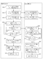
- FIG. 29 is a flowchart showing the flow of the communication process of FIG. In the process shown in FIG. 29, in addition to the process shown in FIG. 7 in the first embodiment, a process of updating the used block encryption key is performed.
- the terminal device A102 Upon receiving the block cipher communication approval message 2802 from the terminal device B 103, the terminal device A102 encrypts data for the unit data amount of the communication data with the block cipher key 2803, and generates encrypted communication data 2804 (S906). . Then, the terminal apparatus A102 transmits the encrypted communication data 2804 to the terminal apparatus B103 (S907). The terminal device B103 receives the encrypted communication data 2804 (S908). Then, the terminal apparatus B103 decrypts the encrypted communication data 2804 with the block encryption key 2805, and obtains communication data (S909).
- the terminal device A102 checks whether there is untransmitted communication data (S910). If there is no untransmitted communication data (NO in S910), the terminal device A102 randomizes the block encryption key 2803 using a hash function or the like to generate a block encryption key 2806 (S911). The terminal device A102 sets the block encryption key 2806 for the next encrypted communication, discards the block encryption key 2803 (S912), and ends the process (S913). On the other hand, if there is untransmitted communication data (YES in S910), the terminal apparatus A102 returns the process to S906. Similarly, the terminal device B103 confirms whether there is unreceived communication data (S914).
- the terminal device B103 determines that there is no unreceived communication data. If there is no unreceived communication data (NO in S914), the terminal apparatus A102 randomizes the block encryption key 2805 with a hash function or the like to generate a block encryption key 2807 (S915). Note that the hash function used for randomization by the terminal apparatus B103 is the same as that used by the terminal apparatus A102 in S911. Therefore, the block encryption key 2807 generated here is the same as the block encryption key 2806 generated in S911. Then, the terminal device B103 ends the process (S815). On the other hand, if there is unreceived communication data (YES in S914), the terminal apparatus B103 returns the process to S908.
- FIG. 30 is a functional block diagram illustrating functional configurations of terminal device A 102 and terminal device B 103 according to the fifth embodiment.
- the terminal device shown in FIG. 30 includes a hash function processing unit 818 (block encryption key generation unit) in addition to the functions provided in the terminal device shown in FIG. Further, the processing of the block encryption key update unit 817 is different.
- the block cipher key update unit 817 deletes the currently used block cipher key from the block cipher key storage unit 814 and sets the next block cipher key. However, if there is only one remaining block encryption key and there is no next block encryption key, the block encryption key update unit 817 passes the currently used block encryption key to the hash function processing unit. The block encryption key update unit 817 receives a new block encryption key from the hash function processing unit 818 and stores it in the block encryption key storage unit 814.
- the hash function processing unit 818 receives the block encryption key from the block encryption key update unit 817.
- the hash function processing unit 818 randomizes the received block encryption key with a hash function or the like to generate a new block encryption key. Then, the generated block encryption key is passed to the block encryption key update unit 817.
- the encryption system 1 when the remaining block encryption key is one, a new block encryption key is generated from the currently used block encryption key. Thereby, the safety
- Embodiment 6 FIG. In the sixth embodiment, a description will be given of increasing the remaining Burnham encryption key in the first to fifth embodiments when the remaining amount of the Burnham encryption key becomes smaller than a certain amount. This prevents a shortage of Vernam encryption keys.
- the above-described function added to the first embodiment is shown.
- the same amount of encryption key as that of the data to be encrypted is required. For this reason, when the data to be encrypted is enormous, the consumption of the encryption key is enormously proportional. Therefore, in the sixth embodiment, when the remaining amount of the Burnham encryption key becomes smaller than a predetermined amount, the remaining Burnham encryption key is increased to increase the amount of the Burnham encryption key. Let For example, when the Burnham encryption key is halved, if the remaining Burnham encryption key is subjected to an increase process to make it twice as long, the same number of Burnham encryption keys as the original length can be secured.
- the increase process is repeatedly performed on the Vernam encryption key acquired from the key sharing device, the security of the Vernam encryption key may be reduced.
- the Vernam encryption key acquired from the key sharing device is a true random number, as described in a later embodiment, if the Vernam encryption key is increased using a pseudo-random number, the security of the Vernam encryption key is increased. May decrease. Therefore, in the sixth embodiment, the number of times that the increasing process is performed on the Vernam encryption key acquired from the key sharing apparatus is limited.
- FIG. 31 shows that when the terminal device A 102 and the terminal device B 103 start encryption communication using the Burnham encryption and the remaining amount of the Burnham encryption key becomes smaller than a predetermined amount, the increase processing is performed on the Burnham encryption key. It is a figure which shows the operation
- the terminal device A102 has a Vernam encryption key 3101 for the Vernam encryption.
- the terminal device B103 also has a Vernam encryption key 3102.
- the terminal device A102 has a block encryption key 3113 for block encryption.
- the terminal device B103 also has a block encryption key 3115. It is assumed that the block encryption key 3113 held by the terminal device A102 and the block encryption key 3115 held by the terminal device B103 are the same.
- the terminal device A102 Since the process from the start of the process until the terminal device B 103 obtains communication data from the encrypted communication data 3105 generated by the Burnham cipher is the same as the process shown in FIG. If the encrypted communication data 3105 is generated and the remaining amount of the Vernam encryption key becomes smaller than a predetermined amount, the terminal device A102 transmits a Vernam encryption key increase request message 3106 to the terminal device B103. The terminal apparatus B103 that has received the Vernam encryption key increase request message 3106 transmits a Vernam encryption key increase approval message 3107 to the terminal apparatus A102. The terminal device A 102 that has received the Vernam encryption key increase acknowledgment message 3107 performs an increase process on the Vernam encryption key 3101 to generate a new Vernam encryption key 3108.
- the terminal device A102 encrypts communication data with the generated Vernam encryption key 3108 to generate encrypted communication data 3109. Then, the terminal device A102 transmits the generated encrypted communication data 3109 to the terminal device B103. Receiving the encrypted communication data 3109, the terminal device B103 performs an increase process on the Vernam encryption key 3102 to generate a new Vernam encryption key 3110. The terminal device B103 decrypts the encrypted communication data 3109 with the generated Vernam encryption key 3110 to obtain communication data. Note that the terminal device A 102 and the terminal device B 103 increase the Vernam encryption key by the same method shared in advance.
- the terminal device A102 and the terminal device B103 perform the same increase process every time the remaining amount of the current Vernam encryption key becomes smaller than the predetermined amount up to a predetermined number of times. On the other hand, when the increase process is performed a predetermined number of times, the increase process is not performed even if the Vernam encryption key is smaller than the predetermined amount, and the following processes are executed.
- the terminal device A102 sends a block cipher switching request message 3111 to the terminal device.
- the terminal apparatus B103 that has received the block cipher switching request message 3111 transmits a block cipher switching approval message 3112 to the terminal apparatus A102.
- the terminal device A 102 that has received the block cipher switching approval message 3112 encrypts the communication data with the block cipher key 3113 and generates encrypted communication data 3114.
- the terminal device A102 transmits the generated encrypted communication data 3114 to the terminal device B103.
- the terminal apparatus B 103 that has received the encrypted communication data 3114 decrypts the encrypted communication data 3114 with the block encryption key 3115 to obtain communication data.
- FIGS. 32 to 34 are flowcharts showing the flow of the communication process of FIG. In the process shown in FIGS. 32 to 34, in addition to the process of FIG. 5 in the first embodiment, a process for increasing the Vernam encryption key is performed.
- the processing from S1001 to S1012 is the same as the processing from S101 to S112 shown in FIG.
- the terminal device A102 checks whether the remaining amount of the Vernam encryption key is less than a predetermined amount (S1013). If the remaining amount is greater than or equal to a predetermined amount (NO in S1013), the process returns to S1007. On the other hand, if the remaining amount is less than the predetermined amount (YES in S1013), the process proceeds to S1014. Then, the terminal device A102 confirms whether the number of times the process for increasing the Vernam encryption key has been performed so far is less than a predetermined limit number (S1014). If the number of times of increasing processing is equal to or greater than a predetermined number (NO in S1014), the process proceeds to S1025. On the other hand, when the number of times of increasing processing is less than the predetermined number of times (YES in S1014), the terminal device A102 transmits a Vernam encryption key increase request message 3106 to the terminal device B103 (S1015).
- the terminal apparatus B103 receives the Vernam encryption key increase request message 3106 (S1016). Then, the terminal apparatus B103 transmits a Vernam encryption key increase approval message 3107 to the terminal apparatus A102 (S1017). The terminal device A102 receives the Vernam encryption key increase approval message 3107 (S1018). Then, an increase process is performed on the Burnham encryption key 3101 to generate a new Burnham encryption key 3108 (S1019). The terminal device A102 encrypts data for the unit data amount of the communication data with the generated Vernam encryption key 3108, and generates encrypted communication data 3109 (S1020). Then, the terminal device A102 transmits the encrypted communication data 3109 to the terminal device B103 (S1021).
- the terminal device B103 receives the encrypted communication data 3109 (S1022). Then, the terminal apparatus B103 performs an increase process on the Burnham encryption key 3102 to generate a new Burnham encryption key 3110 (S1023). The terminal device B103 decrypts the encrypted communication data 3109 with the generated Vernam encryption key 3110 to obtain communication data (S1024). After transmitting the encrypted communication data 3109 to the terminal apparatus B103 in S1021, the terminal apparatus A102 returns the process to S1011.
- the terminal device A102 continues to encrypt communication data with the Burnham cipher (S1025).
- the processing from S1026 to S1041 is the same as the processing from S108 to S123 shown in FIG.
- FIG. 35 is a functional block diagram illustrating functional configurations of the terminal device A 102 and the terminal device B 103 according to the sixth embodiment.
- the terminal device shown in FIG. 35 includes a Vernam encryption key increasing unit 819 in addition to the functions provided in the terminal device shown in FIG.
- the Burnham encryption key increase unit 819 acquires the remaining Burnham encryption key from the Burnham encryption key storage unit 813 and performs an increase process.
- the Burnham encryption key obtained as a result of the increase process is passed to the Burnham encryption key storage unit 813.
- the remaining Burnham encryption key when the remaining amount of the Burnham encryption key becomes less than the predetermined amount, the remaining Burnham encryption key is subjected to an increase process to obtain the remaining amount of the Burnham encryption key. Increase. This prevents a shortage of Vernam encryption keys. In addition, by restricting the number of times that the increase process is performed on the Vernam encryption key acquired from the key sharing device, the security of the Vernam encryption key is prevented from being lowered more than a predetermined level.
- Embodiment 7 FIG.
- the Vernam encryption key is increased by mixing pseudo random numbers at a constant rate with the remaining Burnham encryption key. This prevents the shortage of the Burnham encryption key while maintaining the randomness of the Burnham encryption key.
- FIG. 36 is a diagram for explaining the processing of the Vernam encryption key increasing unit 819 in the seventh embodiment.
- the Burnham encryption key increasing unit 819 includes a pseudo random number generator 3601 inside.
- the Burnham encryption key increasing unit 819 decomposes the unit into small units, for example, one bit. Then, the Burnham encryption key increasing unit 819 inserts the pseudo random number 3603 received from the pseudo random number generator 3601 between the decomposed Vernam encryption keys 3602.
- the Burnham encryption key increasing unit 819 generates a new Burnham encryption key 3604 from the input Burnham encryption key 3602 and outputs it.
- the length of the new Burnham encryption key 3604 is twice the length of the entered Burnham encryption key 3602.
- Embodiment 8 FIG.
- the eighth embodiment an example different from the seventh embodiment of the method for increasing the Vernam encryption key described in the sixth embodiment will be described.
- pseudo random numbers are generated by a hash function or an encryption method using the remaining Vernam encryption key as a seed, and the obtained pseudo random number is used as a new Vernam encryption key.
- the Burnham encryption key is prevented from being depleted while maintaining the randomness of the Burnham encryption key.
- FIG. 37 is a diagram for explaining the processing of the Vernam encryption key increasing unit 819 in the eighth embodiment.
- the Burnham encryption key increasing unit 819 includes a pseudo random number generator 3701 and a hash function 3702 therein.
- the Burnham encryption key increasing unit 819 combines the pseudorandom number 3704 received from the pseudorandom number generator 3701 and the Vernum encryption key 3703 and inputs the combined value to the hash function 3702.
- the combination of the pseudo random number 3704 and the Burnham encryption key 3703 is, for example, adding the pseudo random number 3704 before or after the Burnham encryption key 3703.
- the data randomized by the hash function 3702 is output as a new Vernam encryption key 3705.
- the Burnham encryption key increasing unit 819 generates a new Burnham encryption key 3705 from the input Burnham encryption key 3703 and outputs it.
- the length of the new Vernam cryptographic key 3705 is made equal to the length of the original Vernam cryptographic key by the hash function 3702.
- Embodiment 9 FIG.
- the first to eighth embodiments have been described on the assumption that the terminal device is connected to the key sharing device.
- the terminal device is a mobile terminal such as a mobile phone
- a situation in which the terminal device and the key sharing device are not connected may occur.
- the amount of encryption key held between the terminal devices is different because the timing for performing the transfer process of the Vernam encryption key or the block encryption key from the key sharing device to the terminal device does not match between the terminal devices.
- Different cases can occur.
- the terminal device A102 obtains a Vernam encryption key from the key sharing device C104 at a certain time. Thereafter, it is assumed that a new Vernam encryption key is shared between the key sharing device C104 and the key sharing device D105.
- the terminal device B103 has acquired a Vernam encryption key from the key sharing device D105. Then, the terminal device B103 has a Vernam encryption key that the terminal device A102 does not have. In this case, when encryption communication is performed between the terminal device A102 and the terminal device B103, the Vernam encryption key of the terminal device A102 is insufficient first. Therefore, in the ninth embodiment, before performing encrypted communication, information on the Vernam encryption key held by each other is shared between the terminal devices, and the encrypted communication is performed according to the status of the mutually owned Vernam encryption key. Explain switching.
- FIGS. 38 and 39 are flowcharts showing the communication processing flow of FIG. 4 in the ninth embodiment.
- a process of sharing the remaining amount of the Burnham encryption key between terminal devices is performed in advance.
- the terminal device A102 confirms the amount of the Burnham encryption key 401 held (S1101), and transmits a Burnham encryption communication request message 403 to the terminal device B103 together with the remaining value of the Burnham encryption key 401 (S1102).
- the terminal device B103 receives the Vernam encryption communication request message 403 from the terminal device A102 (S1103). Then, the terminal apparatus B103 confirms the amount of the Burnham encryption key 402 that is held (S1104), and calculates the amount of data that can be encrypted using the Burnham encryption (S1105). Then, the terminal apparatus B103 transmits a Vernam encryption communication approval message 404 to the terminal apparatus A102 together with the remaining value of the Vernam encryption key 402 (S1106).
- the terminal device A102 receives the Vernam encryption communication approval message 404 from the terminal device B103 (S1107). Then, the terminal device A102 calculates the amount of data that can be encrypted using Vernam encryption (S1108). In addition, the terminal device A102 performs encryption using the Vernam encryption key 401 on the data corresponding to the unit data amount in the communication data, and generates encrypted communication data 405 (S1109). Then, the terminal device A102 transmits the encrypted communication data 405 to the terminal device B103 (S1110). The terminal device B103 receives the encrypted communication data 405 from the terminal device A102 (S1111). Then, the terminal apparatus B103 obtains communication data by decrypting the encrypted communication data 405 using the Vernam encryption key 402 (S1112).
- the terminal device A102 checks whether there is untransmitted communication data (S1113). If there is no untransmitted communication data (NO in S1113), the terminal device A102 ends the process (S1114). On the other hand, if there is untransmitted communication data (YES in S1113), terminal device A102 advances the process to S1115.
- the terminal device A102 checks whether the amount of data that can be encrypted using the Vernam encryption is equal to or larger than the unit data amount to be encrypted at one time (S1115). At this time, the terminal device A102 calculates the amount of data that the terminal device A102 can currently perform encrypted communication with the Burnham cipher from the data amount calculated in (S1108). Also, the terminal device A102 calculates the amount of data that the terminal device B103 can perform encrypted communication with the Vernam encryption at the present time from the remaining amount of the Vernam encryption key held by the terminal device B103 received together with the Vernam encryption communication approval message 404. To do.
- the terminal apparatus A102 returns the process to S1109. On the other hand, if the smaller data amount is less than the unit data amount (NO in S1115), the terminal device A102 transmits a block cipher switching request message 406 to the terminal device B103 (S1116).
- the processing from S1117 to S1125 is the same as the processing from S115 to S123 shown in FIG.
- FIG. 40 shows a case where encryption communication using block cipher is started because the Vernam encryption key of the terminal device B 103 is insufficient at the time when the terminal device A 102 and the terminal device B 103 start encryption communication in the ninth embodiment. It is a figure which shows an operation
- the terminal device A 102 confirms the amount of the Vernam encryption key 4001 that it holds, and transmits a Vernam encryption communication request message 4004 to the terminal device B 103.
- the terminal device B103 that has received the Burnham encryption communication request message 4004 confirms that the Burnham encryption key has been exhausted, and transmits a Burnham encryption communication rejection message 4005.
- the terminal device A102 that has received the Burnham encryption communication rejection message 4005 transmits a block encryption communication request message 4006 to the terminal device B103.
- Receiving the block cipher communication request message 4006, the terminal device B103 transmits a block cipher communication approval message 4007 to the terminal device A102.
- the subsequent processing is the same as the processing shown in FIG.
- FIG. 41 is a flowchart showing the flow of the communication process of FIG. 40.
- the terminal device A102 confirms the amount of the Vernam encryption key 4001 held (S1201), and transmits a Vernam encryption communication request message 4004 to the terminal device B103 (S1202).
- the terminal device B103 receives the Vernam encryption communication request message 4004 (S1203).
- the terminal apparatus B103 confirms the amount of the Vernam encryption key that is held (S1204), and calculates that the amount of data that can be encrypted using the Vernam encryption is insufficient (S1205).
- the terminal apparatus B103 transmits a Vernam encryption communication rejection message 4005 to the terminal apparatus A102 (S1206).
- the terminal device A102 receives the Vernam encryption communication rejection message 4005 (S1207).
- the terminal device A102 transmits a block cipher communication request message 4006 to the terminal device B103 (S1208).
- the processing from S1209 to S1217 is the same as the processing from S203 to S211 shown in FIG.
- FIG. 42 is a flowchart illustrating a process flow of the transmission control unit 803 of the terminal device 801 according to the ninth embodiment.
- the transmission control unit 803 acquires remaining amount information indicating whether or not the remaining amount of the Burnham encryption key is insufficient from the Burnham encryption key management unit 805 (S1301). If the remaining amount of the Vernam encryption key is not insufficient (NO in S1302), the transmission control unit 803 advances the process to S1303. If the remaining amount is insufficient (YES in S1302), the transmission control unit 803 performs the process in S1312. The process proceeds (S1302).
- the transmission control unit 803 transmits a Vernam encryption communication request message to the terminal device B 103 via the communication interface 802 (S1303), and receives the message from the terminal device B 103 (S1304). If the received message is a Vernam encryption communication approval message, the transmission control unit 803 advances the process to S1306, and if the received message is a Burnham encryption communication rejection message, the transmission control unit 803 advances the process to S1312.
- FIG. 43 is a flowchart illustrating a process flow of the reception control unit 804 of the terminal device 801 according to the ninth embodiment.
- the reception control unit 804 receives the Vernam encryption communication request message or the block encryption communication request message from the terminal device A102 via the communication interface 802 (S1401). The reception control unit 804 advances the process to S1403 when receiving the Vernam encryption request message, and advances the process to S1412 when receiving the block encryption request message (S1402).
- the reception control unit 804 acquires remaining amount information indicating whether or not the remaining amount of the Burnham encryption key is insufficient from the Burnham encryption key management unit 805 (S1403). If the remaining amount of the Burnham encryption key is insufficient (YES in S1403), the reception control unit 804 advances the process to S1404. If the remaining amount of the Burnham encryption key is not insufficient (NO in S1403), the reception control unit 804 performs the process. The process proceeds to S1405. If the remaining amount of the Burnham encryption key is insufficient, the reception control unit 804 transmits a Burnham encryption communication rejection message to the terminal device A102 (S1404), and advances the process to S1413.
- the processing from S1405 to S1415 is the same as the processing from S403 to S413 shown in FIG.
- the encryption system 1 by sharing the remaining amount of the Vernam encryption key held between the terminal devices, there is a difference in the owned Vernam encryption key. Even in such a case, the encryption method can be switched.
- the encryption method is simply switched in accordance with the terminal device A102 or the terminal device B103 with the smaller remaining amount of the Vernam encryption key.
- the terminal device A102 there may be a case where there is a difference in the Vernam encryption key held by the terminal device A102 and the terminal device B103. That is, some of the Vernam encryption keys held by the terminal device A102 are not held by the terminal device B103, and some of the Vernam encryption keys held by the terminal device B103 are stored by the terminal device A102. It is possible that you do not have one. In this case, it is necessary to switch the encryption method in accordance with the remaining amount of the Vernam encryption key held in common by the terminal device A102 and the terminal device B103.
- the terminal device when the terminal device acquires the Vernam encryption key from the key sharing device, the terminal device counts the number of bits of the Vernam encryption key. For example, first, when the terminal device acquires a 1000-bit Vernam encryption key from the key sharing device, the terminal device counts that the Vernam encryption key from the first bit to the 1000th bit has been acquired. Next, when the terminal device acquires a 500-bit Vernam encryption key from the key sharing device, the terminal device counts that the Vernam encryption key from the 1001st bit to the 1500th bit is acquired. The terminal device also counts the number of bits of the used Vernam encryption key. For example, if a 100-bit Vernam encryption key is used first, it is counted that the 1st to 100th Vernam encryption keys are used. Therefore, the terminal device can know how many bits to how many bits of the Burnham encryption key currently remain in a usable state.
- the terminal device A102 instead of checking the remaining amount of the Burnham encryption key, the terminal device A102 checks how many bits to how many bits of the Burnham encryption key remain in use. Then, together with the Vernam encryption communication request message, information indicating how many bits to what number of Vernam encryption keys remain usable is transmitted to the terminal device B103. The terminal device B103 checks how many bits to how many bits of the Burnham encryption key remain in use. Then, the common part of the Vernam encryption key held by the terminal device A102 and the Vernam encryption key held by the terminal device B103 is specified. If the amount of data that can be encrypted in the common part exceeds the unit data amount that is encrypted at one time, the terminal device B103 uses the Vernam encryption key from what bit to what bit together with the Vernam encryption communication approval message.
- the terminal apparatus B103 returns a Vernam encryption communication rejection message.
- the terminal device A102 receives the Vernam encryption communication approval message, the terminal device A102 specifies a common part between the Vernam encryption key held by the terminal device A102 and the Vernam encryption key held by the terminal device B103. Then, the data corresponding to the unit data amount in the communication data is encrypted with the specified common part Vernam encryption key to generate encrypted data, which is transmitted to the terminal device B103.
- the terminal device A102 determines whether the amount of data that can be encrypted using the remaining part of the Vernam encryption key exceeds the unit data amount to be encrypted at one time. Check. If it exceeds, encryption communication by Vernam encryption is performed, and if not, switching to encryption communication by block encryption is performed.
- Embodiment 10 FIG.
- the fourth embodiment it has been described that a plurality of block cipher keys are held, the block cipher keys used for cipher communication are periodically discarded, and cipher communication is performed using a new block cipher key.
- the fourth embodiment has been described on the assumption that the terminal device is connected to the key sharing device.
- the terminal device is a mobile terminal, a situation in which the terminal device and the key sharing device are not connected may occur.
- the encryption key held between the terminal devices is It can be different.
- Embodiment 10 the number of block encryption keys held by each other is shared between the terminal devices before performing the encryption communication, and the encryption communication is performed according to the state of the block encryption key held by each other. The switching will be described.
- each block encryption key is identified by an identification number as shown in FIG.
- the terminal device A102 If the amount of data that can be encrypted using the Burnham cipher exceeds the unit data amount that is encrypted at one time (YES in S1513), the terminal device A102 has a block cipher key with an identification number from what number. Is confirmed (S1514). Then, the terminal device A102 transmits the identification number of the held block encryption key to the terminal device B103 together with the block cipher switching request message 2212 (S1515). The terminal device B103 receives the block cipher switching request message 2212 and the block cipher key identification number (S1516). Then, the terminal apparatus B103 confirms the identification number of the block encryption key that it holds (S1517), and determines the block encryption key that is used for encrypted communication (S1518).
- the terminal device B103 determines the block encryption key having the smallest identification number among the block encryption keys held by both the terminal device A102 and the terminal device B103 as the block encryption key used for encrypted communication. Then, the terminal apparatus B103 transmits the identification number of the determined block encryption key together with the block cipher switching approval message 2213 to the terminal apparatus A102 (S1519).
- the terminal device A102 receives the block cipher switching approval message 2213 and the identified block cipher key identification number (S1520). Then, the terminal device A102 encrypts the communication data with the block encryption key indicated by the received identification number, and generates encrypted communication data 2214 (S1521). Then, the terminal device A102 transmits the encrypted communication data 2214 to the terminal device B103 (S1522). The terminal apparatus B103 receives the encrypted communication data 2214 (S1523). Then, the terminal device B103 decrypts the encrypted communication data 2214 with the block encryption key having the identification number determined in (S1518), and obtains communication data (S1524).
- FIG. 46 is a flowchart showing a communication process flow of FIG. 25 in the tenth embodiment.
- a process of sharing block encryption key information between terminal devices in advance is performed.
- the terminal device A102 confirms the amount of the Burnham encryption key that is held and grasps that the Burnham encryption key is insufficient (S1601). When the amount of data that can be encrypted using the Burnham encryption is less than the unit data amount that is encrypted at a time, it is determined that the Burnham encryption key is insufficient. Then, the terminal device A102 confirms from what identification number to what number the terminal device A102 has a block encryption key (S1602). Then, the terminal device A102 transmits the identification number of the block encryption key held together with the block cipher switching request message 2507 to the terminal device B103 (S1603). The terminal device B103 receives the block cipher switching request message 2507 and the block cipher key identification number (S1604).
- the terminal apparatus B103 confirms the identification number of the block encryption key that it holds (S1605), and determines the block encryption key that is used for encrypted communication (S1606). For example, the terminal device B103 determines the block encryption key having the smallest identification number among the block encryption keys held by both the terminal device A102 and the terminal device B103 as the block encryption key used for encrypted communication. Then, the terminal device B103 transmits the identification number of the determined block encryption key to the terminal device A102 together with the block cipher switching approval message 2508 (S1607).
- the terminal device A102 receives the block cipher switching approval message 2508 and the identified block cipher key identification number (S1608). Then, the terminal device A102 encrypts the communication data with the block encryption key indicated by the received identification number, and generates encrypted communication data 2509 (S1609). Then, the terminal device A102 transmits the encrypted communication data 2509 to the terminal device B103 (S1610). The terminal device B103 receives the encrypted communication data 2509 (S1611). Then, the terminal apparatus B103 decrypts the encrypted communication data 2509 with the block encryption key having the identification number determined in (S1606), and obtains communication data (S1612).
- the processing from S1613 to S1618 is the same as the processing from S810 to S815 in FIG.
- FIG. 47 is a flowchart showing a process flow of the transmission control unit 803 of the terminal device 801 in the tenth embodiment.
- the processing from S1701 to S1708 is the same as the processing from S301 to S308 shown in FIG.
- the transmission control unit 803 checks the identification number of the block cipher key block cipher key storage unit 814 has stored (S1709).
- the transmission control unit 803 transmits the block cipher key identification number stored in the block cipher key storage unit 814 to the terminal device B 103 together with the block cipher switching request message via the communication interface 802 (S1710).
- the transmission control unit 803 receives the identification number of the block cipher key used for cipher communication together with the block cipher switching approval message from the terminal device B103 (S1711), and advances the process to S1715.
- the transmission control unit 803 confirms the identification number of the block encryption key stored in the block encryption key storage unit 814 (S1712).
- the transmission control unit 803 transmits the block cipher key identification number stored in the block cipher key storage unit 814 to the terminal device B 103 together with the block cipher communication request message via the communication interface 802 (S1713).
- the transmission control unit 803 receives the identification number of the block cipher key used in the cipher communication together with the block cipher communication approval message from the terminal device B103 (S1714), and advances the process to S1715.
- the transmission control unit 803 uses the block encryption key of the identification number received in S1711 or S1714 to cause the block encryption unit 808 to encrypt the data for the unit data amount of the communication data, and obtain the encrypted communication data (S1715). ). Then, the transmission control unit 803 transmits the encrypted communication data to the terminal device B103 (S1716). Subsequently, the transmission control unit 803 confirms whether there is untransmitted communication data (S1717). If there is no untransmitted communication data (NO in S1717), the transmission control unit 803 ends the process. On the other hand, if there is untransmitted communication data (YES in S1717), the transmission control unit 803 returns the process to S1715.
- FIG. 48 is a flowchart showing a process flow of the reception control unit 804 of the terminal device 801 in the tenth embodiment.
- the processing from S1801 to S1807 is the same as the processing from S401 to S407 shown in FIG.
- the reception control unit 804 receives the block cipher switching request message and the identification number of the block cipher key held by the terminal device A102 from the terminal device A102 (S1808).
- the reception control unit 804 confirms the identification number of the block encryption key stored in the block encryption key storage unit 814 (S1809).
- the reception control unit 804 uses the identification number of the block encryption key held by the terminal device A102 received in (S1808) and the identification number of the block encryption key held by the terminal device B103 confirmed in (S1809) for encryption communication.
- a block encryption key is determined (S1810).
- the reception control unit 804 transmits the confirmed block cipher key identification number together with the block cipher switching approval message to the terminal device A102 via the communication interface 802 (S1811), and advances the process to S1815.
- the reception control unit 804 confirms the identification number of the block encryption key stored in the block encryption key storage unit 814 (S1812).
- the reception control unit 804 uses the identification number of the block encryption key held by the terminal device A102 received in (S1802) and the identification number of the block encryption key held by the terminal device B103 confirmed in (S1812) for encryption communication.
- the block encryption key is determined (S1813).
- the reception control unit 804 transmits the determined block cipher key identification number together with the block cipher communication approval message to the terminal device A102 via the communication interface 802 (S1814), and the process proceeds to S1815.
- the reception control unit 804 receives the encrypted communication data from the terminal device A102 (S1815).
- the reception control unit 804 transmits the received encrypted communication data to the block decryption unit 809 and decrypts it with the block encryption key having the identification number determined in S1810 or S1813 to generate communication data (S1816).
- the generated communication data is stored in the reception data storage unit 812.
- the reception control unit 804 confirms whether there is unreceived communication data (S1817). If there is no unreceived communication data (NO in S1817), the reception control unit 804 ends the process. On the other hand, if there is unreceived communication data (YES in S1817), reception control unit 804 returns the process to S1815.
- the encryption system 1 As described above, in the encryption system 1 according to the tenth embodiment, there is a difference in the block encryption keys held by sharing the amount of block encryption keys held between the terminal devices. However, the encryption method can be switched.
- Embodiment 11 FIG.
- the description has been given of updating the current block cipher key by randomizing a hash function or the like when performing encryption by block cipher when the remaining block cipher key becomes one.
- encryption communication cannot be performed when the number of block encryption key updates is not synchronized due to a communication error or the like. Therefore, in the eleventh embodiment, before the encryption communication is performed, the update counts of the block encryption keys held by the terminal devices are shared, and the update counts of the block encryption keys held by each other are synchronized. Will be described.
- FIG. 49 is a flowchart showing a communication process flow of FIG. 28 in the eleventh embodiment.
- processing for sharing the number of block encryption key updates between terminal devices is performed in advance.
- the terminal device A102 confirms the amount of the Vernam encryption key that is held, and grasps that the Vernam encryption key is insufficient (S1901). When the amount of data that can be encrypted using the Burnham encryption is less than the unit data amount that is encrypted at a time, it is determined that the Burnham encryption key is insufficient. Then, the terminal device A102 confirms the number of updates of the block encryption key that it holds (S1902). Then, the terminal device A102 transmits the block encryption key update count together with the block cipher communication request message 2801 to the terminal device B103 (S1903). The terminal device B103 receives the block cipher communication request message 2801 and the number of block cipher key updates from the terminal device A102 (S1904).
- the terminal device B103 confirms the number of updates of the block encryption key that it holds (S1905).
- the terminal apparatus B103 determines the number of updates of the block encryption key used for encrypted communication (S1906). For example, for the block encryption key, the terminal device B103 determines the larger number of updates, out of the number of updates in the terminal device A102 and the number of updates in the terminal device B103, as the number of updates of the block encryption key used in encrypted communication. .
- the terminal apparatus B103 transmits the determined block encryption key update count together with the block cipher communication approval message 2804 to the terminal apparatus A102 (S1907).
- the terminal device B103 If the block encryption key determined in (S1906) has not reached the determined number of updates, the terminal device B103 repeatedly executes the update process until the determined number of updates is reached (S1908). As a result, the block encryption key is used for encrypted communication. Note that the case where the number of update times has not been reached means that the number of update times is smaller than the number of update times that have been confirmed.
- the terminal device A102 receives the block cipher switching approval message 2804 and the confirmed block cipher key update count (S1909). If the block encryption key is not the received update count, the terminal device A102 repeatedly executes the update process until the received update count is reached (S1910). As a result, the block encryption key is used for encrypted communication. The case where the received update count is not reached means that the update count is smaller than the received update count.
- the terminal device A102 encrypts the communication data with the block encryption key used in the encrypted communication, and generates the encrypted communication data 2804 (S1911). Then, the terminal device A102 transmits the encrypted communication data 2804 to the terminal device B103 (S1912). The terminal device B103 receives the encrypted communication data 2804 (S1913). Then, the terminal apparatus B103 decrypts the encrypted communication data 2804 with the block encryption key used in the encrypted communication, and obtains communication data (S1914).
- FIG. 50 is a flowchart showing a process flow of the transmission control unit 803 of the terminal device 801 in the eleventh embodiment.
- the transmission control unit 803 checks the block encryption key update count stored in the block encryption key storage unit 814 (S2009). The transmission control unit 803 transmits the block cipher key update count stored in the block cipher key storage unit 814 to the terminal device B 103 via the communication interface 802 together with the block cipher switching request message (S2010). Then, the transmission control unit 803 receives the number of updates of the block cipher key used for cipher communication together with the block cipher switching approval message from the terminal apparatus B103 (S2011), and advances the process to S2015.
- the transmission control unit 803 checks the block encryption key update count stored in the block encryption key storage unit 814 (S2012).
- the transmission control unit 803 transmits the block cipher key update count stored in the block cipher key storage unit 814 to the terminal device B 103 via the communication interface 802 together with the block cipher communication request message (S2013).
- the transmission control unit 803 receives the number of updates of the block cipher key used for cipher communication together with the block cipher communication approval message from the terminal device B103 (S2014), and advances the process to S2015.
- the transmission control unit 803 If the block encryption key has not received the update count received in S2011 or S2014, the transmission control unit 803 repeatedly executes the update process until the received update count is reached (S2015). As a result, the block encryption key is used for encrypted communication.
- the transmission control unit 803 causes the block encryption unit 808 to encrypt data corresponding to the unit data amount in the communication data with the block encryption key used in the encrypted communication, and obtains encrypted communication data (S2016). Then, the transmission control unit 803 transmits the encrypted communication data to the terminal device B103 (S2017). Subsequently, the transmission control unit 803 checks whether there is untransmitted communication data (S2018). If there is no untransmitted communication data (NO in S2018), the transmission control unit 803 ends the process. On the other hand, if there is untransmitted communication data (YES in S2018), the transmission control unit 803 returns the process to S2016.
- FIG. 51 is a flowchart showing a process flow of the reception control unit 804 of the terminal device 801 according to the eleventh embodiment.
- the reception control unit 804 receives the block cipher switching request message and the number of updates of the block cipher key held by the terminal device A102 from the terminal device A102 (S2108).
- the reception control unit 804 confirms the update count of the block encryption key stored in the block encryption key storage unit 814 (S2109).
- the reception control unit 804 is used for encryption communication from the number of updates of the block encryption key held by the terminal device A102 received in (S2108) and the number of updates of the block encryption key held by the terminal device B103 confirmed in (S2109).
- the block encryption key and the number of updates are determined (S2110).
- the reception control unit 804 transmits the determined block encryption key update count together with the block cipher switching approval message to the terminal device A102 via the communication interface 802 (S2111), and the process proceeds to S2115.
- the reception control unit 804 confirms the number of updates of the block encryption key stored in the block encryption key storage unit 814 (S2112).
- the reception control unit 804 is used for cryptographic communication from the number of updates of the block encryption key held by the terminal device A102 received in (S2102) and the number of updates of the block encryption key held by the terminal device B103 confirmed in (S2112).
- the block encryption key and the number of updates are determined (S2113).
- the reception control unit 804 transmits the determined block cipher key update count together with the block cipher communication approval message to the terminal device A102 via the communication interface 802 (S2114), and the process proceeds to S2115.
- the reception control unit 804 repeatedly executes the update process until the determined update count is reached (S2115). As a result, the block encryption key is used for encrypted communication.
- the reception control unit 804 receives the encrypted communication data from the terminal device A102 (S2116).
- the reception control unit 804 transmits the received encrypted communication data to the block decryption unit 809, and generates the communication data by decrypting the encrypted communication data with the block encryption key used in the encrypted communication (S2117).
- the generated communication data is stored in the reception data storage unit 812. Subsequently, the reception control unit 804 confirms whether there is unreceived communication data (S2118).
- reception control unit 804 ends the process. On the other hand, if there is unreceived communication data (YES in S2118), reception control unit 804 returns the process to S2116.
- the encryption system 1 As described above, in the encryption system 1 according to Embodiment 11, there is a difference in the number of updates of the block encryption key held by sharing the number of updates of the block encryption key held between the terminal devices. Even in some cases, the encryption method can be switched.
- Embodiment 12 FIG.
- the Burnham encryption key and the block encryption key are stored in a nonvolatile memory or the like when not in use.
- the Vernam encryption key and the block encryption key are loaded into a volatile memory such as a RAM immediately before use, and are erased from the nonvolatile memory. This prevents the already used Vernam encryption key and block encryption key from being taken out due to unauthorized power shutdown or the like.
- a Vernam encryption key and a block encryption key (hereinafter referred to as an encryption key in this embodiment) need to be held in the apparatus even when the apparatus is powered off. Therefore, an unused encryption key is stored in a nonvolatile storage device such as an HDD.
- the encryption key used for the encryption or decryption is deleted, and the same again The same encryption key is not used in the device.
- the encryption key deletion process may not be performed normally. In particular, in this case, there may occur a state in which encrypted communication data flows through the communication path and the encryption key remains in the apparatus. In this state, there is a risk that the encryption key is illegally extracted from the device and the encrypted communication data is decrypted.
- FIG. 52 is an explanatory diagram of the operation of the terminal device according to the twelfth embodiment.
- the terminal device loads an encryption key stored in a nonvolatile storage device such as an HDD into a volatile memory immediately before use, and encrypts the data stored in the HDD or the nonvolatile memory. Erase the key.
- the encryption key does not remain in the device even when the power of the device is shut down, so that the encryption key is not revealed by unauthorized extraction, and there is a risk of decrypting the encrypted communication data. Absent.
- the Vernam encryption key storage unit 813 and the block encryption key storage unit 814 are nonvolatile storage devices such as HDDs.
- the Burnham encryption unit 806, the Burnham decryption unit 807, the block encryption unit 808, and the block decryption unit 809 are the Burnham encryption key storage unit 813 or the block An encryption key is acquired from the encryption key storage unit 814.
- the Burnham encryption unit 806, the Burnham decryption unit 807, the block encryption unit 808, and the block decryption unit 809 store the acquired encryption key in a volatile storage device such as a RAM (Random Access Memory) and acquire it.
- a volatile storage device such as a RAM (Random Access Memory)
- the encryption key is deleted from the Vernam encryption key storage unit 813 or the block encryption key storage unit 814.
- the Burnham encryption unit 806, the Burnham decryption unit 807, the block encryption unit 808, and the block decryption unit 809 perform encryption and decryption with the encryption key stored in the volatile storage device.
- Embodiment 13 FIG. In the thirteenth embodiment, the remaining amount of the Vernam encryption key and the block encryption key, the encryption method used in the current encryption communication, and notification of when the encryption method is switched will be described. This enables the user of the terminal device to intuitively grasp the current encryption communication and encryption key status.
- the Vernam encryption key and the block encryption key (hereinafter referred to as the encryption key in this embodiment) are held in the terminal device, so that it is not easy for the user to grasp the information.
- encryption processing and decryption processing in encrypted communication are also performed in the terminal device. Therefore, it is not easy for the user to grasp the switching of the encryption method when, for example, the cipher communication using the Vernam cipher is switched to the cipher communication using the block cipher due to the lack of the Vernam cipher key.
- Switching between cryptographic schemes means that the security of cryptographic communications changes.
- the remaining amount of the encryption key serves as an index indicating a period until the encryption method is switched. Therefore, it is important that the user can grasp this information. Therefore, in the thirteenth embodiment, during encryption communication, the current remaining amount of encryption key and encryption method are notified to the user by screen display, sound, and terminal vibration.
- FIG. 53 is a functional block diagram illustrating functional configurations of terminal device A 102 and terminal device B 103 according to the thirteenth embodiment.
- the encryption key remaining amount notification control unit 820 (remaining amount notification unit), the encryption method notification control unit 821 (remaining amount notification unit), and screen display A control unit 822, an audio output control unit 823, a vibration control unit 824, a display 825, a speaker 826, and a vibration device 827 are provided.
- the encryption key remaining amount notification control unit 820 acquires the remaining amount information of the Vernam encryption key from the Vernam encryption key storage unit 813 and acquires the remaining amount information of the block encryption key from the block encryption key storage unit 814. Then, the encryption key remaining amount notification control unit 820 processes the acquired Vernam encryption key remaining amount information and block encryption key remaining amount information into notification information for notifying the user of the remaining amount of the encryption key. And sent to the screen display control unit 822, the audio output control unit 823, and the vibration control unit 824.
- the encryption method notification control unit 821 acquires information indicating the currently used encryption method from the transmission control unit 803 and the reception control unit 804. Then, the encryption method notification control unit 821 converts the information indicating the acquired encryption method into information for notifying the user of the encryption method, and displays a screen display control unit 822, a sound output control unit 823, and a vibration control unit. Send to 824. In addition, when the encryption method is switched, the encryption method notification control unit 821 sends information indicating that the encryption method has been switched to the screen display control unit 822, the audio output control unit 823, and the vibration control unit 824.
- the screen display control unit 822 instructs the display 825 to display a screen based on the information received from the encryption key remaining amount notification control unit 820 and the encryption method notification control unit 821.
- the audio output control unit 823 instructs the speaker 826 to output audio from the information received from the encryption key remaining amount notification control unit 820 and the encryption method notification control unit 821.
- the vibration control unit 824 instructs the vibration device 827 to vibrate the terminal from the information received from the encryption key remaining amount notification control unit 820 and the encryption method notification control unit 821.
- the display 825 is a device that can display pictures and characters on a screen such as a liquid crystal display.
- the speaker 826 is a device that can output sound.
- the vibration device 827 is a device that can vibrate the terminal.
- the encryption key remaining amount notification control unit 820 always displays the remaining amount of the Burnham encryption key and the remaining amount of the block encryption key on the display 825 using numerical values or the like.
- the encryption key remaining amount notification control unit 820 displays information indicating that when the Vernam encryption key is smaller than a predetermined amount and the increase process described in the sixth embodiment is executed.
- sound is output from the speaker 826, and the vibration device 827 is vibrated.
- the encryption method notification control unit 821 displays information indicating that on the display 825 and outputs a sound from the speaker 826 to vibrate the vibration device 827.
- the encryption key remaining amount notification control unit 820 displays information indicating that fact on the display 825. And a sound is output from the speaker 826 to vibrate the vibration device 827.
- the encryption key remaining amount notification control unit 820 and the encryption method notification control unit 821 perform the encryption key conversion and the encryption method switching each time the safety of the encryption communication is reduced, to the user. Notice. For example, each time an encryption key is converted or an encryption method is switched, the color of information displayed on the display 825, the character, symbol, figure, or type of sound displayed according to the encryption key or encryption method used. The length of the sound, the type of vibration, and the vibration interval may be changed.
- the encryption key remaining amount notification control unit 820 and the encryption method notification control unit 821 perform encryption key conversion or encryption method switching, and encryption key conversion or The user may be notified that the encryption method is switched. Thereby, for example, the user can be prompted to acquire the Vernam encryption key from the key sharing apparatus.
- Embodiment 14 FIG. In the fourteenth embodiment, a method for realizing encrypted communication in the above-described embodiment will be described.
- the communication processing before performing cryptographic communication can be realized by SIP (Session Initiation Protocol).
- SIP Session Initiation Protocol
- a Vernam encryption communication request message and a block encryption communication request message are performed by an INVITE message, and encryption key information is described by SDP (Session Description Protocol).
- the Vernam encryption communication acknowledgment message and the block encryption communication acknowledgment message are response messages indicating 200 OK, and the encryption key information and the like are described in SDP as in the INVITE message.
- the Vernam encryption communication rejection message is a response message indicating 488 Not Acceptable.
- the encryption communication and the switching of the encryption method during the encryption communication can be realized by SRTP (Secure Real-Time Protocol). That is, the encryption method and encryption key to be started are determined by negotiation according to SIP, and switching between encryption communication and encryption method can be realized by communication according to SRTP.
- SRTP Secure Real-Time Protocol
- FIG. 54 is a diagram illustrating an example of a hardware configuration of the terminal device 801.
- the terminal device 801 includes a CPU 911 (also referred to as a central processing unit, a central processing unit, a processing unit, an arithmetic unit, a microprocessor, a microcomputer, and a processor) that executes a program.
- a CPU 911 also referred to as a central processing unit, a central processing unit, a processing unit, an arithmetic unit, a microprocessor, a microcomputer, and a processor
- the CPU 911 includes a ROM 913, a RAM 914, a display 825, a keyboard 902 (K / B), a speaker 826, a vibration device 827, a communication board 915 (an example of a communication interface 802), and a magnetic disk device 920 (HDD, fixed disk) via a bus 912. Device) and control these hardware devices.
- a storage device such as an optical disk device or a memory card read / write device may be used.
- the magnetic disk device 920 is connected via a predetermined fixed disk interface.
- an operating system 921 OS
- a window system 922 a program group 923
- a file group 924 are stored in the magnetic disk device 920 or the ROM 913.
- the programs in the program group 923 are executed by the CPU 911, the operating system 921, and the window system 922.
- the program group 923 includes “transmission control unit 803”, “reception control unit 804”, “burnum encryption key management unit 805”, “burnum encryption unit 806”, “burnum decryption unit 807”, “block” in the above description.
- the program is read and executed by the CPU 911.
- the file group 924 includes information and data stored in the “transmission data storage unit 811”, the “reception data storage unit 812”, the “Burnam encryption key storage unit 813”, and the “block encryption key storage unit 814” in the above description.
- Signal values, variable values, and parameters are stored as items in the “database”.
- the “database” is stored in a recording medium such as a disk or a memory.
- Information, data, signal values, variable values, and parameters stored in a storage medium such as a disk or memory are read out to the main memory or cache memory by the CPU 911 via a read / write circuit, and extracted, searched, referenced, compared, and calculated.
- Used for the operation of the CPU 911 such as calculation / processing / output / printing / display.
- Information, data, signal values, variable values, and parameters are temporarily stored in the main memory, cache memory, and buffer memory during the operation of the CPU 911 for extraction, search, reference, comparison, calculation, calculation, processing, output, printing, and display. Is remembered.
- the key sharing device 1101 also includes a CPU 911 that executes a program, like the terminal device 801.
- the CPU 911 is connected to the ROM 913, the RAM 914, the keyboard 902 (K / B), the communication board 915 (an example of the communication interface 1102), and the magnetic disk device 920 via the bus 912, and controls these hardware devices.
- an operating system 921 OS
- a window system 922 a program group 923
- a file group 924 are stored in the magnetic disk device 920 or the ROM 913.
- the programs in the program group 923 are executed by the CPU 911, the operating system 921, and the window system 922.
- the program group 923 includes the functions described as “Burnam encryption key sharing unit 1103”, “Vernam encryption key transfer unit 1104”, “Block encryption key sharing unit 1106”, “Block encryption key transfer unit 1107”, etc. Software and programs for executing and other programs are stored.
- the file group 924 information, data, signal values, variable values, and parameters stored in the “Burnam encryption key storage unit 1105” and the “block encryption key storage unit 1108” in the above description are included in each item of “Database”. Is remembered as
- the arrows in the flowchart mainly indicate input / output of data and signals, and the data and signal values are recorded in a memory of the RAM 914, other recording media such as an optical disk, and an IC chip.
- Data and signals are transmitted online by a bus 912, signal lines, cables, other transmission media, and radio waves.
- what is described as “to part” in the above description may be “to circuit”, “to device”, “to device”, “to means”, and “to function”. It may be “step”, “ ⁇ procedure”, “ ⁇ processing”.
- ⁇ device may be “ ⁇ circuit”, “ ⁇ equipment”, “ ⁇ means”, “ ⁇ function”, and “ ⁇ step”, “ ⁇ procedure”, “ May be “processing”. That is, what is described as “ ⁇ unit” may be realized by firmware stored in the ROM 913. Alternatively, only software, hardware such as elements, devices, substrates, and wirings, a combination of software and hardware, or a combination of firmware may be used. Firmware and software are stored in a recording medium such as ROM 913 as a program. The program is read by the CPU 911 and executed by the CPU 911. That is, the program causes a computer or the like to function as the “ ⁇ unit” described above. Alternatively, the procedure or method of “unit” described above is executed by a computer or the like.
- Vernam encryption key management unit 805 Vernam encryption key management unit, 806 Vernam encryption unit, 807 Vernum decryption unit, 808 block encryption unit, 809 block decryption unit, 810 Vernam encryption key acquisition unit, 811 transmission data storage unit, 812 Received data storage unit, 813 Vernam encryption key storage unit, 814 block encryption key storage unit, 815 block encryption key acquisition unit, 816 encryption key conversion unit, 817 block encryption key update unit, 818 hash function processing unit, 819 Vernam encryption key increase 820 encryption key remaining amount notification control unit 821 encryption method notification control unit 822 screen display control unit 823 audio output control unit 824 vibration control unit 825 display 826 speaker 827 vibration device 1101 key sharing device 1102 Communication interface, 1103 Vernam encryption key sharing unit, 1104 Vernam encryption
Abstract
Description
ワンタイムパッド暗号の典型的な例としては、通信データと暗号鍵とについて1ビットづつ排他的論理和等を計算して、計算した結果を暗号化通信データとするバーナム暗号がある。
ブロック暗号の例としては、Camellia(登録商標)、AES(Advanced Encryption Standard)等がある。
しかし、ワンタイムパッド暗号は、解読不可能であり、ブロック暗号よりも安全性が高いと言える。
また、通信データの重要性は主観的な基準であり、暗号化の対象となっている通信データの重要性は通信開始時、もしくは、事前に利用者又は管理者が判断しなければならない。そのため、通信データの入力が行われた時点から通信データが暗号化されるまでの間に利用者による重要性の判断が必要となり、暗号通信に関する処理のすべてを自動化することができない。
さらに、音声による通話中に重要な会話内容が含まれる場合などのように、通信データの種類によっては、重要性が事前に判断できないものもある。そのため、暗号対象の通信データの重要性を基準として暗号方式を切り替えることは、汎用的に有効な手段ではない。
ワンタイムパッド暗号で使用するワンタイムパッド暗号鍵を記憶するワンタイムパッド暗号鍵記憶部と、
前記ワンタイムパッド暗号鍵記憶部が記憶したワンタイムパッド暗号鍵の一部を順に用いて、通信データをワンタイムパッド暗号により暗号化して暗号化データを生成するワンタイムパッド暗号化部と、
ブロック暗号で使用するブロック暗号鍵を記憶するブロック暗号鍵記憶部と、
前記ブロック暗号鍵記憶部が記憶したブロック暗号鍵を用いて、通信データをブロック暗号により暗号化して暗号化データを生成するブロック暗号化部と、
前記ワンタイムパッド暗号鍵記憶部が記憶したワンタイムパッド暗号鍵の残りビット数に応じて、通信データを前記ワンタイムパッド暗号化部に暗号化させるか、前記ブロック暗号化部に暗号化させるかを制御する暗号化制御部と
を備えることを特徴とする。
以下の説明において、処理装置は後述するCPU911等である。記憶装置は後述するROM913、RAM914、磁気ディスク920等の記憶装置である。つまり、処理装置、記憶装置はハードウェアである。
実施の形態1では、バーナム暗号用の暗号鍵(以下、バーナム暗号鍵)が枯渇した場合に、暗号方式をバーナム暗号からCamellia(登録商標)、AESといったブロック暗号に切り替える技術について説明する。これにより、バーナム暗号鍵が不足することによる暗号通信の中断を引き起こすことなく、バーナム暗号鍵が補充されるまでの期間においても、暗号通信の継続を可能にする。
インターネットなどのネットワーク101には、端末装置A102と端末装置B103とが接続される。また、鍵共有装置C104と鍵共有装置D105がネットワーク101、もしくは、ネットワーク101とは物理的もしくは論理的に接続されていないネットワーク106と接続される。さらに、端末装置A102と鍵共有装置C104とは、USB(Universal Serial Bus)などの通信ケーブル107で接続されている。同様に、端末装置B103と鍵共有装置D105とは、通信ケーブル108で接続されている。
なお、端末装置A102と端末装置B103とは、それぞれ、暗号化データを送信する送信側通信装置(暗号化装置)でもあり、暗号化データを受信する受信側通信装置(復号装置)でもある。以下では、端末装置A102を送信側通信装置の例とし、端末装置B103を受信側通信装置の例とする。
また、端末装置A102は鍵共有装置C104からバーナム暗号鍵を取得し、端末装置B103は鍵共有装置D105からバーナム暗号鍵を取得するものとする。
図2は、鍵共有装置C104と鍵共有装置D105とが、ネットワーク101、もしくは、ネットワーク101とは物理的もしくは論理的に接続されていないネットワーク106を介して、バーナム暗号鍵の共有を行う場合の動作概要を示す図である。
鍵共有装置C104と鍵共有装置D105とは、ネットワーク101もしくはネットワーク106を介して、所定の方法(鍵共有アルゴリズム)によりバーナム暗号鍵201を共有する。なお、バーナム暗号鍵201を共有する方法は、どのような方法であっても構わない。例えば、鍵共有装置C104と鍵共有装置D105とが、物理的もしくは論理的に安全な通信路で接続された上でバーナム暗号鍵201を共有すればよい。実施の形態1では、一例として、量子暗号通信による鍵共有が行われるものとする。
図3は、端末装置A102が、通信ケーブル107を介して鍵共有装置C104からバーナム暗号鍵301を取得する場合の動作概要を示す図である。
まず、端末装置A102は、バーナム暗号鍵要求メッセージ302を鍵共有装置C104へ送信する。鍵共有装置C104は、バーナム暗号鍵要求メッセージ302を受信した後、保有しているバーナム暗号鍵301を端末装置A102へ送信する。バーナム暗号鍵301を受信した端末装置A102は、バーナム暗号鍵301を記憶装置に記憶する。
なお、端末装置B103が、通信ケーブル108を介して鍵共有装置D105からバーナム暗号鍵を取得する方法も同様である。
図4は、端末装置A102と端末装置B103とがバーナム暗号による暗号通信を開始し、バーナム暗号用の暗号鍵が不足した時点からブロック暗号による暗号通信に方式の切り替えを行う場合の動作概要を示す図である。
なお、暗号通信の事前準備として、端末装置A102はバーナム暗号用の暗号鍵401を保有している。また、端末装置B103もバーナム暗号鍵402を保有している。端末装置A102が保有するバーナム暗号鍵401と、端末装置B103が保有するバーナム暗号鍵402とは、前述の方法により、それぞれ鍵共有装置C104と鍵共有装置D105から取得したものである。実施の形態1においては、バーナム暗号鍵401とバーナム暗号鍵402は、同一のものであるとする。
また、端末装置A102はブロック暗号用のブロック暗号鍵408を保有している。また、端末装置B103もブロック暗号鍵410を保有している。端末装置A102が保有するブロック暗号鍵408と、端末装置B103が保有するブロック暗号鍵410とは同一のものであるとする。端末装置A102と端末装置B103との間におけるブロック暗号鍵の共有方法については、後の実施の形態で説明する。
バーナム暗号通信要求メッセージ403を受信した端末装置B103は、保有しているバーナム暗号鍵402の残量を確認する。ここでは、バーナム暗号鍵402には、バーナム暗号鍵401と同じ残量があるものとする。そこで、端末装置B103は、バーナム暗号鍵402の残量に基づき、バーナム暗号を行うことができるデータ通信量を算出する。そして、端末装置B103は、バーナム暗号通信了承メッセージ404を端末装置A102へ送信する。
バーナム暗号通信了承メッセージ404を受信した端末装置A102は、バーナム暗号鍵401を用いて、通信データにバーナム暗号による暗号化を施し、暗号化通信データ405を生成する。そして、端末装置A102は、生成した暗号化通信データ405を端末装置B103へ送信する。
暗号化通信データ405を受信した端末装置B103は、バーナム暗号鍵402で暗号化通信データ405を復号し、通信データを得る。なお、バーナム暗号鍵401とバーナム暗号鍵402とは、同一であるため、バーナム暗号鍵401で暗号化された暗号化通信データ405は、バーナム暗号鍵402で復号可能である。
ブロック暗号切替要求メッセージ406を受信した端末装置B103は、ブロック暗号切替了承メッセージ407を端末装置A102へ送信する。
ブロック暗号切替了承メッセージ407を受信した端末装置A102は、通信データをブロック暗号鍵408で暗号化し、暗号化通信データ409を生成する。そして、端末装置A102は、生成した暗号化通信データ409を端末装置B103へ送信する。
暗号化通信データ409を受信した端末装置B103は、ブロック暗号鍵410で暗号化通信データ409を復号し、通信データを得る。なお、ブロック暗号鍵408とブロック暗号鍵410とは、同一であるため、ブロック暗号鍵408で暗号化された暗号化通信データ409は、ブロック暗号鍵410で復号可能である。
端末装置B103は、端末装置A102からバーナム暗号通信要求メッセージ403を受信する(S103)。すると、端末装置B103は、保有しているバーナム暗号鍵402の量を確認し、バーナム暗号で暗号通信を行うことができるデータ量を算出する(S104)。そして、端末装置B103は、バーナム暗号通信了承メッセージ404を端末装置A102へ送信する(S105)。
端末装置A102は、端末装置B103からバーナム暗号通信了承メッセージ404を受信する(S106)。すると、端末装置A102は、通信データのうち単位データ量分のデータをバーナム暗号鍵401で暗号化して、暗号化通信データ405を生成する。(S107)。なお、単位データ量分のデータとは、予め決められたビット数のデータである。あるいは、予め決められた単位のデータ、例えば、1ファイルのデータ等である。また、例えば、携帯電話における音声通話データの場合であれば、10~20ミリ秒程度の短い時間毎の音声通話データである。そして、端末装置A102は、暗号化通信データ405を端末装置B103へ送信する(S108)。
端末装置B103は、端末装置A102から暗号化通信データ405を受信する(S109)。すると、端末装置B103は、バーナム暗号鍵402で暗号化通信データ405を復号し、通信データを得る(S110)。
バーナム暗号で暗号通信を行うことができるデータ量が単位データ量以上であれば(S113でYES)、端末装置A102はS107へ処理を戻す。一方、バーナム暗号で暗号通信を行うことができるデータ量が単位データ量未満であれば(S113でNO)、端末装置A102はブロック暗号切替要求メッセージ406を端末装置B103へ送信する(S114)。
端末装置A102は、ブロック暗号切替了承メッセージ407を受信する(S117)。すると、端末装置A102は、通信データのうち単位データ量分のデータをブロック暗号鍵408で暗号化して、暗号化通信データ409を生成する(S118)。そして、端末装置A102は、暗号化通信データ409を端末装置B103へ送信する(S119)。
端末装置B103は、暗号化通信データ409を受信する(S120)。すると、端末装置B103は、ブロック暗号鍵410で暗号化通信データ409を復号し、通信データを得る(S121)。
図6は、端末装置A102と端末装置B103とが暗号通信を開始する時点で、バーナム暗号鍵が不足しているため、ブロック暗号による暗号通信を開始する場合の動作概要を示す図である。
なお、端末装置A102はブロック暗号用のブロック暗号鍵603を保有している。また、端末装置B103もブロック暗号鍵605を保有している。端末装置A102が保有するブロック暗号鍵603と、端末装置B103が保有するブロック暗号鍵605とは同一のものであるとする。端末装置A102と端末装置B103との間におけるブロック暗号鍵の共有方法については、後の実施の形態で説明する。
ブロック暗号通信要求メッセージ601を受信した端末装置B103は、ブロック暗号通信了承メッセージ602を端末装置A102へ送信する。
ブロック暗号通信了承メッセージ602を受信した端末装置A102は、ブロック暗号鍵603を用いて、通信データにブロック暗号による暗号化を施し、暗号化通信データ604を生成する。そして、端末装置A102は、生成した暗号化通信データ604を端末装置B103へ送信する。
暗号化通信データ604を受信した端末装置B103は、ブロック暗号鍵605で暗号化通信データ604を復号し、通信データを得る。なお、ブロック暗号鍵603とブロック暗号鍵605とは、同一であるため、ブロック暗号鍵603で暗号化された暗号化通信データ604は、ブロック暗号鍵605で復号可能である。
端末装置B103は、端末装置A102からブロック暗号通信要求メッセージ601を受信する(S203)。そして、端末装置B103は、ブロック暗号通信了承メッセージ602を端末装置A102へ送信する(S204)。
端末装置A102は、端末装置B103からブロック暗号通信了承メッセージ602を受信する(S205)。すると、端末装置A102は、通信データのうち単位データ量分のデータをブロック暗号鍵603で暗号化して、暗号化通信データ604を生成する(S206)。そして、端末装置A102は、暗号化通信データ604を端末装置B103へ送信する(S207)。
端末装置B103は、暗号化通信データ604を受信する(S208)。すると、端末装置B103は、ブロック暗号鍵605で暗号化通信データ604を復号し、通信データを得る(S209)。
図8は、実施の形態1における端末装置A102及び端末装置B103の機能構成を示す機能ブロック図である。ここで、端末装置A102と端末装置B103とは、同一の機能構成である。そこで、ここでは、端末装置A102と端末装置B103とを端末装置801として説明する。
端末装置801は、通信インターフェイス802、送信制御部803(暗号化制御部)、受信制御部804(復号制御部)、バーナム暗号鍵管理部805、バーナム暗号化部806、バーナム復号部807、ブロック暗号化部808、ブロック復号部809、バーナム暗号鍵取得部810、送信データ記憶部811、受信データ記憶部812、バーナム暗号鍵記憶部813(バーナム復号鍵記憶部)及びブロック暗号鍵記憶部814(ブロック復号鍵記憶部)を備える。
より具体的には、通信インターフェイス802は、鍵共有装置C104や鍵共有装置D105からバーナム暗号鍵を受信するための装置である。
また、通信インターフェイス802は、端末装置801が暗号通信の送信側である場合は受信側となる端末装置に暗号化通信データを送信し、通信インターフェイス802暗号通信の受信側である場合は送信側となる端末装置から暗号化通信データを受信するための装置である。
なお、バーナム暗号鍵管理部805は、バーナム暗号で暗号通信を行うことができるデータ量が、1度に暗号化する単位データ量未満である場合に、バーナム暗号鍵が不足していると判定する。
図9は、端末装置801の送信制御部803の処理の流れを示すフローチャートである。
送信制御部803は、通信インターフェイス802を介して、バーナム暗号通信要求メッセージを端末装置B103へ送信し(S303)、端末装置B103からバーナム暗号通信了承メッセージを受信する(S304)。そして、送信制御部803は、バーナム暗号化部806に通信データのうち単位データ量分のデータを暗号化させ、暗号化通信データを取得する(S305)。送信制御部803は、取得した暗号化通信データを通信インターフェイス802を解して端末装置B103へ送信する(S306)。
送信制御部803は、ブロック暗号通信要求メッセージを端末装置B103に送信し(S311)、端末装置B103からブロック暗号通信了承メッセージを受信し(S312)、S313に処理を進める。
送信制御部803は、ブロック暗号化部808に通信データのうち単位データ量分のデータを暗号化させ、暗号化通信データを取得する(S313)。そして、送信制御部803は、暗号化通信データを端末装置B103へ送信する(S314)。
続いて、送信制御部803は、未送信の通信データの有無を確認する(S315)。未送信の通信データがなければ(S315でNO)、送信制御部803は処理を終了する。一方、未送信の通信データがあれば(S315でYES)、送信制御部803はS313へ処理を戻す。
図10は、端末装置801の受信制御部804の処理の流れを示すフローチャートである。
受信制御部804は、通信インターフェイス802を介して、バーナム暗号了承メッセージを端末装置A102へ送信し(S403)、端末装置A102から暗号化通信データを受信する(S404)。受信制御部804は、受信した暗号化通信データをバーナム復号部807に送信して、復号させ通信データを生成させる(S405)。生成された通信データは、受信データ記憶部812に記憶される。
なお、未受信の通信データがあるか否かは、例えば、所定の時間内に次の暗号化データ、又は、ブロック暗号切替要求メッセージが送信されているかによって判定される。
受信制御部804は、ブロック暗号通信了承メッセージを端末装置A102に送信し(S410)、S411に処理を進める。
受信制御部804は、端末装置A102から暗号化通信データを受信する(S411)。受信制御部804は、受信した暗号化通信データをブロック復号部809に送信して、復号させ通信データを生成させる(S412)。生成された通信データは、受信データ記憶部812に記憶される。
続いて、受信制御部804は、未送信の通信データの有無を確認する(S413)。未送信の通信データがなければ(S413でNO)、受信制御部804は処理を終了する。一方、未送信の通信データがあれば(S413でYES)、受信制御部804はS411へ処理を戻す。
図11は、実施の形態1における鍵共有装置C104及び鍵共有装置D105の機能構成を示す機能ブロック図である。ここで、鍵共有装置C104と鍵共有装置D105とは、同一の機能構成である。そこで、ここでは、鍵共有装置C104と鍵共有装置D105とを鍵共有装置1101として説明する。
鍵共有装置1101は、通信インターフェイス1102、バーナム暗号鍵共有部1103、バーナム暗号鍵転送部1104及びバーナム暗号鍵記憶部1105を備える。
より具体的には、通信インターフェイス1102は、他の鍵共有装置とバーナム暗号鍵を共有するための通信を行うための装置である。
また、通信ケーブル等で接続されている端末装置に、バーナム暗号鍵を送信するための装置である。
実施の形態2では、ブロック暗号鍵の共有方法について説明する。実施の形態2では、実施の形態1において、端末装置A102及び端末装置B103が鍵共有装置C104及び鍵共有装置D105からバーナム暗号鍵を取得する際に、併せてブロック暗号鍵も同時に取得する。これにより、ブロック暗号鍵についても端末装置間で安全に共有する。
図12は、鍵共有装置C104と鍵共有装置D105とがネットワーク101もしくはネットワーク106を介して、バーナム暗号鍵1201及びブロック暗号鍵1202の共有を行う場合の動作概要を示す図である。
鍵共有装置C104と鍵共有装置D105とは、ネットワーク101もしくはネットワーク106を介して、所定の方法(鍵共有アルゴリズム)によりバーナム暗号鍵1201及びブロック暗号鍵1202を共有する。なお、バーナム暗号鍵1201及びブロック暗号鍵1202を共有する方法は、どのような方法であっても構わない。例えば、鍵共有装置C104と鍵共有装置D105とが、物理的もしくは論理的に安全な通信路で接続された上でバーナム暗号鍵1201及びブロック暗号鍵1202を共有すればよい。実施の形態2では、一例として、量子暗号通信による鍵共有が行われるものとする。
図13は、鍵共有装置C104から端末装置A102が通信ケーブル107を介して、バーナム暗号鍵1301及びブロック暗号鍵1302を取得する場合の動作概要を示す図である。
まず、端末装置A102は、暗号鍵要求メッセージ1303を鍵共有装置C104へ送信する。鍵共有装置C104は、暗号鍵要求メッセージ1303を受信した後、保有しているバーナム暗号鍵1301及びブロック暗号鍵1302を端末装置A102へ送信する。バーナム暗号鍵1301及びブロック暗号鍵1302を受信した端末装置A102は、バーナム暗号鍵1301及びブロック暗号鍵1302を記憶する。
なお、端末装置B103が、通信ケーブル108を介して鍵共有装置D105からバーナム暗号鍵及びブロック暗号鍵を取得する方法も同様である。
図14は、実施の形態2における端末装置A102及び端末装置B103の機能構成を示す機能ブロック図である。図14に示す端末装置は、図8に示す端末装置が備える機能に加え、ブロック暗号鍵取得部815を備える。
図15は、実施の形態2における鍵共有装置C104及び鍵共有装置D105の機能構成を説明する機能ブロック図である。図15に示す鍵共有装置は、図11に示す鍵共有装置が備える機能に加え、ブロック暗号鍵共有部1106、ブロック暗号鍵転送部1107及びブロック暗号鍵記憶部1108を備える。
実施の形態3では、バーナム暗号鍵の残量が所定の量よりも少なくなった時点で、残存するバーナム暗号鍵からブロック暗号鍵を生成することについて説明する。これにより、事前にブロック暗号鍵を端末装置間で共有していなくても、バーナム暗号鍵の不足時にブロック暗号による暗号通信に切り替えることを可能とする。
そこで、実施の形態3においては、端末装置A102と端末装置B103とは、暗号通信開始時、バーナム暗号鍵のみを共有しており、ブロック暗号鍵は保持していないものとする。
なお、ここでは、バーナム暗号鍵が不足した時点において、バーナム暗号鍵はブロック暗号鍵の生成に必要となる量が残っているものとして説明する。
図16は、端末装置A102と端末装置B103とがバーナム暗号による暗号通信を開始し、バーナム暗号用の暗号鍵が不足した時点からブロック暗号による暗号通信に方式の切り替えを行う場合の動作概要を示す図である。図16に示す処理では、実施の形態1における図4の処理に加えて、バーナム暗号鍵からブロック暗号鍵を生成する処理が行われる。
なお、暗号通信の事前準備として、端末装置A102はバーナム暗号用のバーナム暗号鍵1601を保有している。また、端末装置B103もバーナム暗号鍵1602を保有している。端末装置A102が保有するバーナム暗号鍵1601と端末装置B103が保有するバーナム暗号鍵1602は、前述の方法により、それぞれ鍵共有装置C104と鍵共有装置D105から取得したものである。実施の形態3においては、バーナム暗号鍵1601とバーナム暗号鍵1602とは、同一のものであるとする。
また、暗号通信前の時点で、端末装置A102と端末装置B103とは、それぞれブロック暗号鍵1608とブロック暗号鍵1610とを保有していない。
ブロック暗号切替了承メッセージ1607を受信した端末装置A102は、残存しているバーナム暗号鍵1601からブロック暗号鍵1608を生成する。端末装置A102は、通信データをブロック暗号鍵1608で暗号化し、暗号化通信データ1609を生成する。そして、端末装置A102は、生成した暗号化通信データ1609を端末装置B103へ送信する。
暗号化通信データ1609を受信した端末装置B103は、残存しているバーナム暗号鍵1602からブロック暗号鍵1610を生成する。端末装置B103は、ブロック暗号鍵1610で暗号化通信データ1609を復号し、通信データを得る。
例えば、端末装置A102と端末装置B103とは、残存するバーナム暗号鍵の一部を、そのままブロック暗号鍵とする。つまり、ブロック暗号鍵が256ビットである場合、残存するバーナム暗号鍵のうち所定の256ビットを切り出してブロック暗号鍵とする。
端末装置B103は、暗号化通信データ1609を受信する(S521)。すると、端末装置B103は、残存しているバーナム暗号鍵1602からブロック暗号鍵1610を生成する(S522)。そして、端末装置B103は、ブロック暗号鍵1610で暗号化通信データ1609を復号し、通信データを得る(S523)。
図19は、端末装置A102と端末装置B103が暗号通信を開始する時点で、バーナム暗号鍵が不足しているため、ブロック暗号による暗号通信を開始する場合の動作概要を示す図である。図19に示す処理では、実施の形態1における図6の処理に加えて、バーナム暗号鍵からブロック暗号鍵を生成する処理が行われる。
なお、ここでは、通信開始時点でバーナム暗号鍵は枯渇しておらず、ブロック暗号鍵の生成に必要な量以上残っているものとする。
ブロック暗号通信了承メッセージ1903を受信した端末装置A102は、残存しているバーナム暗号鍵1901からブロック暗号鍵1904を生成する。端末装置A102は、通信データをブロック暗号鍵1904で暗号化し、暗号化通信データ1905を生成する。そして、端末装置A102は、生成した暗号化通信データ1905を端末装置B103へ送信する。
暗号化通信データ1905を受信した端末装置B103は、残存しているバーナム暗号鍵1906からブロック暗号鍵1907を生成する。端末装置B103は、ブロック暗号鍵1907で暗号化通信データ1905を復号し、通信データを得る。
端末装置B103は、暗号化通信データ1905を受信する(S609)。すると、端末装置B103は、残存しているバーナム暗号鍵1906からブロック暗号鍵1907を生成する(S610)。そして、端末装置B103は、ブロック暗号鍵1907で暗号化通信データ1905を復号し、通信データを得る(S611)。
図21は、実施の形態3における端末装置A102及び端末装置B103の機能構成を示す機能ブロック図である。図21に示す端末装置は、図8に示す端末装置が備える機能に加え、暗号鍵変換部816を備える。
そこで、バーナム暗号鍵が不足する前に、残存するバーナム暗号鍵からブロック暗号鍵を生成してもよい。例えば、端末装置が鍵共有装置からバーナム暗号鍵を取得した時点で、残存するバーナム暗号鍵からブロック暗号鍵を生成してもよい。この場合、ブロック暗号鍵を生成するために必要な量以上、バーナム暗号鍵が残存しており、残存するバーナム暗号鍵からブロック暗号鍵を生成できないということがない。
実施の形態4では、ブロック暗号鍵を複数保持しておき、暗号通信に利用しているブロック暗号鍵を定期的に破棄し、新しいブロック暗号鍵を使って暗号通信を行うことについて説明する。これにより、ブロック暗号による暗号通信をより安全な通信として実現する。
以下の説明では、一例として実施の形態1に上記の機能を追加したものを示す。
図22は、端末装置A102と端末装置B103とがバーナム暗号による暗号通信を開始し、バーナム暗号用の暗号鍵が不足した時点からブロック暗号による暗号通信に方式の切り替えを行う場合の動作概要を示す図である。図22に示す処理では、実施の形態1における図4の処理に加えて、利用したブロック暗号鍵を破棄し、次のブロック暗号鍵を設定する処理が行われる。
なお、暗号通信の事前準備として、端末装置A102はバーナム暗号用のバーナム暗号鍵2201と複数のブロック暗号鍵2202~2204(ブロック暗号鍵1~n)を保有している。また、端末装置B103もバーナム暗号鍵2205と複数のブロック暗号鍵2206~2208(ブロック暗号鍵1~n)を保有している。実施の形態4においては、バーナム暗号鍵2201とバーナム暗号鍵2205とは同一のものであり、ブロック暗号鍵2202~2204とブロック暗号鍵2206~2208とも、それぞれ同一のものである。
なお、ブロック暗号鍵の1~nの値は、ブロック暗号鍵を識別する識別番号(識別情報)である。
ブロック暗号切替了承メッセージ2213を受信した端末装置A102は、通信データをブロック暗号鍵2202で暗号化し、暗号化通信データ2214を生成し、端末装置B103へ送信する。
暗号化通信データ2214を受信した端末装置B103は、ブロック暗号鍵2206で暗号化通信データ2214を復号し、通信データを得る。
端末装置A102と端末装置B103とは、それぞれ、ブロック暗号鍵2202、ブロック暗号鍵2206を破棄する。そして、端末装置A102と端末装置B103とは、それぞれ、次にブロック暗号鍵による暗号化を行う場合には、それぞれブロック暗号鍵2203、ブロック暗号鍵2207を用いるように設定する。
端末装置B103は、暗号化通信データ2214を受信する(S720)。すると、端末装置B103は、ブロック暗号鍵2206で暗号化通信データ2214を復号し、通信データを得る(S721)。
同様に、端末装置B103は、未受信の通信データの有無を確認する(S725)。なお、例えば、端末装置B103は、端末装置A102から所定の時間内に次の通信データを受信しない場合、未受信の通信データがないと判定する。未受信の通信データがなければ(S725でNO)、端末装置A102はブロック暗号鍵2206を破棄し、次にブロック暗号鍵による暗号化を行う場合には、ブロック暗号鍵2207を用いるように設定する(S726)。そして、端末装置B103は、処理を終了する(S727)。一方、未受信の通信データがあれば(S725でYES)、端末装置B103はS720へ処理を戻す。
図25は、端末装置A102と端末装置B103が暗号通信を開始する時点で、バーナム暗号鍵が不足しているため、ブロック暗号による暗号通信を開始する場合の動作概要を示す図である。図25に示す処理では、実施の形態1における図6の処理に加えて、利用したブロック暗号鍵を破棄し、次のブロック暗号鍵を設定する処理が行われる。
なお、暗号通信の事前準備として、端末装置A102は複数のブロック暗号鍵2501~2503(ブロック暗号鍵1~n)を保有している。また、端末装置B103も複数のブロック暗号鍵2504~2506(ブロック暗号鍵1~n)を保有している。端末装置A102が保有するブロック暗号鍵2501~2503と、端末装置B103が保有するブロック暗号鍵2504~2506とは、それぞれ同一のものであるとする。
ブロック暗号通信了承メッセージ2508を受信した端末装置A102は、ブロック暗号鍵2501を用いて、通信データにブロック暗号による暗号化を施し、暗号化通信データ2509を生成する。そして、端末装置A102は、生成した暗号化通信データ2509を端末装置B103へ送信する。
暗号化通信データ2509を受信した端末装置B103は、ブロック暗号鍵2504で暗号化通信データ2509を復号し、通信データを得る。
暗号通信の終了後、端末装置A102と端末装置B103とは、それぞれブロック暗号鍵2501、ブロック暗号鍵2504を破棄し、次にブロック暗号鍵による暗号化を行う場合には、それぞれブロック暗号鍵2502、ブロック暗号鍵2505を用いるように設定する。
端末装置A102と端末装置B103とは、それぞれ、ブロック暗号鍵2501、ブロック暗号鍵2504を破棄する。そして、端末装置A102と端末装置B103とは、それぞれ、次にブロック暗号鍵による暗号化を行う場合には、それぞれブロック暗号鍵2502、ブロック暗号鍵2505を用いるように設定する。
端末装置B103は、暗号化通信データ2509を受信する(S808)。すると、端末装置B103は、ブロック暗号鍵2504で暗号化通信データ2509を復号し、通信データを得る(S809)。
同様に、端末装置B103は、未受信の通信データの有無を確認する(S813)。なお、例えば、端末装置B103は、端末装置A102から所定の時間内に次の通信データを受信しない場合、未受信の通信データがないと判定する。未受信の通信データがなければ(S813でNO)、端末装置B103はブロック暗号鍵2504を破棄し、次にブロック暗号鍵による暗号化を行う場合には、ブロック暗号鍵2505を用いるように設定する(S814)。そして、端末装置B103は、処理を終了する(S815)。一方、未受信の通信データがあれば(S813でYES)、端末装置A102はS808へ処理を戻す。
図27は、実施の形態4における端末装置A102及び端末装置B103の機能構成を示す機能ブロック図である。図27に示す端末装置は、図8に示す端末装置が備える機能に加え、ブロック暗号鍵更新部817を備える。
実施の形態5では、実施の形態4において、ブロック暗号鍵が残り1つとなった時点でブロック暗号による暗号化を行う場合には、現在のブロック暗号鍵をハッシュ関数などのランダム化によって更新することについて説明する。これにより、同じブロック暗号鍵を繰り返し用いることによる安全性の低下を防ぐ技術について説明する。
そこで、実施の形態5では、ブロック暗号鍵の残りが1つしかない時にブロック暗号による暗号通信を行った場合、そのブロック暗号鍵をハッシュ関数などを用いたランダム化によって更新する。
図28は、端末装置A102と端末装置B103とが暗号通信を開始する時点で、バーナム暗号鍵が不足しており、かつ、ブロック暗号鍵の残りが1つしかない場合の動作概要を示す図である。
なお、端末装置A102はブロック暗号用のブロック暗号鍵2803を保有している。また、端末装置B103もブロック暗号鍵2805を保有している。端末装置A102が保有するブロック暗号鍵2803と、端末装置B103が保有するブロック暗号鍵2805とは、それぞれ同一のものであるとする。
ブロック暗号通信了承メッセージ2802を受信した端末装置A102は、ブロック暗号鍵2803を用いて、通信データにブロック暗号による暗号化を施し、暗号化通信データ2804を生成する。そして、端末装置A102は、生成した暗号化通信データ2804を端末装置B103へ送信する。
暗号化通信データ2804を受信した端末装置B103は、ブロック暗号鍵2805で暗号化通信データ2804を復号し、通信データを得る。
暗号通信の終了時、端末装置A102と端末装置B103とは、それぞれ、ブロック暗号鍵2803、ブロック暗号鍵2805にハッシュ関数などによるランダム化を施し、ブロック暗号鍵2806、ブロック暗号鍵2807を生成する。そして、端末装置A102と端末装置B103とは、次にブロック暗号鍵による暗号化を行う場合には、それぞれブロック暗号鍵2806、ブロック暗号鍵2807を用いるように設定する。このとき、端末装置A102と端末装置B103とは、それぞれ、ブロック暗号鍵2803、2805を削除する。
端末装置B103は、暗号化通信データ2804を受信する(S908)。すると、端末装置B103は、ブロック暗号鍵2805で暗号化通信データ2804を復号し、通信データを得る(S909)。
同様に、端末装置B103は、未受信の通信データの有無を確認する(S914)。なお、例えば、端末装置B103は、端末装置A102から所定の時間内に次の通信データを受信しない場合、未受信の通信データがないと判定する。未受信の通信データがなければ(S914でNO)、端末装置A102はブロック暗号鍵2805にハッシュ関数などによるランダム化を施し、ブロック暗号鍵2807を生成する(S915)。なお、端末装置B103がランダム化に用いるハッシュ関数などは、S911で端末装置A102が用いたものと同じものである。したがって、ここで、生成されるブロック暗号鍵2807と、S911で生成されるブロック暗号鍵2806とは同じである。そして、端末装置B103は、処理を終了する(S815)。一方、未受信の通信データがあれば(S914でYES)、端末装置B103は処理をS908へ戻す。
図30は、実施の形態5における端末装置A102及び端末装置B103の機能構成を説明する機能ブロック図である。図30に示す端末装置は、図27に示す端末装置が備える機能に加え、ハッシュ関数処理部818(ブロック暗号鍵生成部)を備える。また、ブロック暗号鍵更新部817の処理が異なる。
但し、ブロック暗号鍵の残りが1つしかなく、次のブロック暗号鍵が存在しない場合は、ブロック暗号鍵更新部817は、現在使われているブロック暗号鍵をハッシュ関数処理部に渡す。そして、ブロック暗号鍵更新部817は、ハッシュ関数処理部818から新しいブロック暗号鍵を受け取り、ブロック暗号鍵記憶部814に記憶する。
実施の形態6では、実施の形態1~5において、バーナム暗号鍵の残量が一定量よりも少なくなった時点で、残存するバーナム暗号鍵を増大することについて説明する。これにより、バーナム暗号鍵が不足することを防止する。
以下の説明では、一例として、実施の形態1に上記の機能を追加したものを示す。
例えば、バーナム暗号鍵が半分になった時点で、残っているバーナム暗号鍵に増大処理を施し、2倍の長さにすれば、元の長さと同じだけのバーナム暗号鍵が確保できる。
そこで、実施の形態6においては、鍵共有装置から取得したバーナム暗号鍵に対して増大処理を実行する回数を制限する。
図31は、端末装置A102と端末装置B103とがバーナム暗号による暗号通信を開始し、バーナム暗号鍵の残量が事前に決められた量よりも少なくなった時点で、バーナム暗号鍵に増大処理を施す場合の動作概要を示す図である。
暗号通信の事前準備として、端末装置A102はバーナム暗号用のバーナム暗号鍵3101を保有している。また、端末装置B103もバーナム暗号鍵3102を保有している。バーナム暗号鍵3101とバーナム暗号鍵3102とは同一のものであるとする。
また、端末装置A102はブロック暗号用のブロック暗号鍵3113を保有している。また、端末装置B103もブロック暗号鍵3115を保有している。端末装置A102が保有するブロック暗号鍵3113と、端末装置B103が保有するブロック暗号鍵3115とは同一のものであるとする。
もし、暗号化通信データ3105を生成することでバーナム暗号鍵の残量が事前に決められた量より少なくなった場合、端末装置A102はバーナム暗号鍵増大要求メッセージ3106を端末装置B103へ送信する。
バーナム暗号鍵増大要求メッセージ3106を受信した端末装置B103は、バーナム暗号鍵増大了承メッセージ3107を端末装置A102へ送信する。
バーナム暗号鍵増大了承メッセージ3107を受信した端末装置A102は、バーナム暗号鍵3101に増大処理を施し、新たなバーナム暗号鍵3108を生成する。端末装置A102は、生成したバーナム暗号鍵3108で通信データを暗号化し、暗号化通信データ3109を生成する。そして、端末装置A102は、生成した暗号化通信データ3109を端末装置B103へ送信する。
暗号化通信データ3109を受信した端末装置B103は、バーナム暗号鍵3102に増大処理を施し、新たなバーナム暗号鍵3110を生成する。端末装置B103は、生成したバーナム暗号鍵3110で暗号化通信データ3109を復号し、通信データを得る。
なお、端末装置A102と端末装置B103とは、予め共有された同一の方法により、バーナム暗号鍵を増大させるものとする。
ブロック暗号切替要求メッセージ3111を受信した端末装置B103は、ブロック暗号切替了承メッセージ3112を端末装置A102へ送信する。
ブロック暗号切替了承メッセージ3112を受信した端末装置A102は、通信データをブロック暗号鍵3113で暗号化し、暗号化通信データ3114を生成する。そして、端末装置A102は、生成した暗号化通信データ3114を端末装置B103へ送信する。
暗号化通信データ3114を受信した端末装置B103は、ブロック暗号鍵3115で暗号化通信データ3114を復号し、通信データを得る。
そして、端末装置A102は、今までにバーナム暗号鍵の増大処理を行った回数が事前に決められた制限回数より少ないかを確認する(S1014)。増大処理を行った回数が事前に定められた回数以上の場合(S1014でNO)、S1025へ処理を進める。一方、増大処理を行った回数が事前に定められた回数より少ない場合(S1014でYES)、端末装置A102は、バーナム暗号鍵増大要求メッセージ3106を端末装置B103へ送信する(S1015)。
端末装置A102は、バーナム暗号鍵増大了承メッセージ3107を受信する(S1018)。すると、バーナム暗号鍵3101に増大処理を施し、新たなバーナム暗号鍵3108を生成する(S1019)。端末装置A102は、生成したバーナム暗号鍵3108で通信データのうち単位データ量分のデータを暗号化し、暗号化通信データ3109を生成する(S1020)。そして、端末装置A102は、暗号化通信データ3109を端末装置B103へ送信する(S1021)。
端末装置B103は、暗号化通信データ3109を受信する(S1022)。すると、端末装置B103は、バーナム暗号鍵3102に増大処理を施し、新たなバーナム暗号鍵3110を生成する(S1023)。端末装置B103は、生成したバーナム暗号鍵3110で暗号化通信データ3109を復号し、通信データを得る(S1024)。
S1021で暗号化通信データ3109を端末装置B103へ送信した後、端末装置A102はS1011へ処理を戻す。
S1026からS1041までの処理は、図5に示すS108からS123までの処理と同様であるため、説明を省略する。
図35は、実施の形態6における端末装置A102及び端末装置B103の機能構成を示す機能ブロック図である。図35に示す端末装置は、図8に示す端末装置が備える機能に加え、バーナム暗号鍵増大部819を備える。
また、鍵共有装置から取得したバーナム暗号鍵に対して、増大処理を実行する回数を制限することにより、バーナム暗号鍵の安全性が所定以上に低下することを防止している。
実施の形態7では、実施の形態6で説明したバーナム暗号鍵の増大方法の一例について説明する。
実施の形態7では、残存するバーナム暗号鍵に一定の割合で擬似乱数を混ぜることによりバーナム暗号鍵を増大させる。これにより、バーナム暗号鍵の乱数性を維持しつつ、バーナム暗号鍵の不足を防止する。
バーナム暗号鍵増大部819は、内部に擬似乱数生成器3601を有する。バーナム暗号鍵増大部819は、バーナム暗号鍵3602が入力されると、小さな単位、例えば1ビットごとに分解する。そして、バーナム暗号鍵増大部819は、擬似乱数生成器3601から受け取った擬似乱数3603を分解したバーナム暗号鍵3602の間に挿入する。
この処理により、バーナム暗号鍵増大部819は、入力されたバーナム暗号鍵3602から新しいバーナム暗号鍵3604を生成し、出力する。この例では、新しいバーナム暗号鍵3604の長さは、入力されたバーナム暗号鍵3602長さの2倍となる。
実施の形態8では、実施の形態6で説明したバーナム暗号鍵の増大方法の、実施の形態7とは異なる例について説明する。
実施の形態8では、残存するバーナム暗号鍵を種として、ハッシュ関数や暗号方式による擬似乱数生成を行い、得られた擬似乱数を新しいバーナム暗号鍵とする。これにより、バーナム暗号鍵の乱数性を維持しつつ、バーナム暗号鍵の枯渇を防止する。
バーナム暗号鍵増大部819は、内部に擬似乱数生成器3701とハッシュ関数3702を有する。バーナム暗号鍵増大部819は、バーナム暗号鍵3703が入力されると、擬似乱数生成器3701から受け取った擬似乱数3704とバーナム暗号鍵3703とを組み合わせ、ハッシュ関数3702に入力する。擬似乱数3704とバーナム暗号鍵3703とを組み合わせるとは、例えば、バーナム暗号鍵3703の前又は後に擬似乱数3704を付加することである。そして、ハッシュ関数3702でランダム化されたものを新しいバーナム暗号鍵3705として出力する。
この処理により、バーナム暗号鍵増大部819は、入力されたバーナム暗号鍵3703から新しいバーナム暗号鍵3705を生成し、出力する。この例では、新しいバーナム暗号鍵3705の長さは、ハッシュ関数3702によって元のバーナム暗号鍵の長さと同じになる。
実施の形態1~8においては、端末装置が鍵共有装置と接続されていることを前提として説明した。しかし、例えば、端末装置が携帯電話等の携帯端末である場合には、端末装置と鍵共有装置が接続されていない状況も起こりうる。この場合、鍵共有装置から端末装置へのバーナム暗号鍵又はブロック暗号鍵の転送処理を行う時期が、端末装置間で一致していないことにより、端末装置間で保有している暗号鍵の量が異なっている場合が起こりえる。
例えば、ある時点で端末装置A102が鍵共有装置C104からバーナム暗号鍵を取得したとする。その後、鍵共有装置C104と鍵共有装置D105との間で新たなバーナム暗号鍵が共有されたとする。そして、端末装置B103が鍵共有装置D105からバーナム暗号鍵を取得したとする。すると、端末装置B103は端末装置A102が保有していないバーナム暗号鍵を保有していることになる。この場合、端末装置A102と端末装置B103との間で暗号通信を行う場合、端末装置A102のバーナム暗号鍵が先に不足することになる。
そこで、実施の形態9では、暗号通信を行う前に端末装置間で互いの保有しているバーナム暗号鍵の情報を共有し、互いの保有しているバーナム暗号鍵の状況に応じて暗号通信を切り替えることを説明する。
図38及び図39は、実施の形態9における図4の通信処理の流れを示すフローチャートである。図38及び図39に示す処理では、実施の形態1における図5の処理に加えて、事前にバーナム暗号鍵の残量を端末装置間で共有する処理が行われる。
端末装置B103は、端末装置A102からバーナム暗号通信要求メッセージ403を受信する(S1103)。すると、端末装置B103は、保有しているバーナム暗号鍵402の量を確認し(S1104)、バーナム暗号で暗号通信を行うことができるデータ量を算出する(S1105)。そして、端末装置B103は、バーナム暗号通信了承メッセージ404をバーナム暗号鍵402の残量値と共に端末装置A102へ送信する(S1106)。
端末装置A102は、端末装置B103からバーナム暗号通信了承メッセージ404を受信する(S1107)。すると、端末装置A102は、バーナム暗号で暗号通信を行うことができるデータ量を算出する(S1108)。また、端末装置A102は、通信データのうち単位データ量分のデータにバーナム暗号鍵401を用いた暗号化を施して、暗号化通信データ405を生成する(S1109)。そして、端末装置A102は、暗号化通信データ405を端末装置B103へ送信する(S1110)。
端末装置B103は、端末装置A102から暗号化通信データ405を受信する(S1111)。すると、端末装置B103は、バーナム暗号鍵402を用いて暗号化通信データ405を復号して通信データを得る(S1112)。
少ない方のデータ量が単位データ量以上であれば(S1115でYES)、端末装置A102はS1109へ処理を戻す。一方、少ない方のデータ量が単位データ量未満であれば(S1115でNO)、端末装置A102はブロック暗号切替要求メッセージ406を端末装置B103へ送信する(S1116)。
図40は、実施の形態9において、端末装置A102と端末装置B103が暗号通信を開始する時点で、端末装置B103のバーナム暗号鍵が不足しているため、ブロック暗号による暗号通信を開始する場合の動作概要を示す図である。
なお、端末装置A102はバーナム暗号鍵4001とブロック暗号鍵4002とを保有しており、端末装置B103はバーナム暗号鍵を保有せず、ブロック暗号鍵4003を保有しているとする。つまり、端末装置B103はバーナム暗号鍵が枯渇している状態であるとする。
バーナム暗号通信要求メッセージ4004を受信した端末装置B103は、バーナム暗号鍵が枯渇していることを確認し、バーナム暗号通信拒否メッセージ4005を送信する。
バーナム暗号通信拒否メッセージ4005を受信した端末装置A102は、端末装置B103にブロック暗号通信要求メッセージ4006を送信する。
ブロック暗号通信要求メッセージ4006を受信した端末装置B103は、端末装置A102にブロック暗号通信了承メッセージ4007を送信する。
以降の処理は、図6に示す処理と同様であるため、説明を省略する。
端末装置B103は、バーナム暗号通信要求メッセージ4004を受信する(S1203)。すると、端末装置B103は、保有しているバーナム暗号鍵の量を確認し(S1204)、バーナム暗号による暗号通信が可能なデータ量が不足していることを算出する(S1205)。そして、端末装置B103は、バーナム暗号通信拒否メッセージ4005を端末装置A102へ送信する(S1206)。
端末装置A102は、バーナム暗号通信拒否メッセージ4005を受信する(S1207)。すると、端末装置A102は、ブロック暗号通信要求メッセージ4006を端末装置B103へ送信する(S1208)。
図42は、実施の形態9における端末装置801の送信制御部803の処理の流れを示すフローチャートである。
図43は、実施の形態9における端末装置801の受信制御部804の処理の流れを示すフローチャートである。
バーナム暗号鍵の残量が不足していた場合、受信制御部804は、バーナム暗号通信拒否メッセージを端末装置A102へ送信し(S1404)、処理をS1413へ進める。
しかし、端末装置A102と端末装置B103とで保有するバーナム暗号鍵にずれがある場合も考えられる。つまり、端末装置A102が保有しているバーナム暗号鍵のうち、一部を端末装置B103が保有しておらず、端末装置B103が保有しているバーナム暗号鍵のうち、一部を端末装置A102が保有していない場合が考えられる。この場合、端末装置A102と端末装置B103とが共通して保有しているバーナム暗号鍵の残量に応じて、暗号方式を切り替える必要がある。
また、端末装置は、使用したバーナム暗号鍵のビット数もカウントしておく。例えば、初めに100ビットのバーナム暗号鍵を使用したのであれば、1ビット目から100ビット目までのバーナム暗号鍵を使用したとカウントする。
したがって、端末装置は、現在何ビット目から何ビット目までのバーナム暗号鍵が使用できる状態で残っているかを知ることができる。
端末装置B103は、何ビット目から何ビット目までのバーナム暗号鍵が使用できる状態で残っているか確認する。そして、端末装置A102が保有するバーナム暗号鍵と端末装置B103が保有するバーナム暗号鍵との共通部分を特定する。共通部分で暗号通信できるデータ量が1度に暗号化する単位データ量を超えていれば、端末装置B103は、バーナム暗号通信了承メッセージとともに、何ビット目から何ビット目までのバーナム暗号鍵が使用できる状態で残っているかを示す情報を端末装置A102へ送信する。一方、共通部分が1度に暗号化する単位データ量を超えていなければ、端末装置B103は、バーナム暗号通信拒否メッセージを返す。
端末装置A102は、バーナム暗号通信了承メッセージを受信した場合、端末装置A102が保有するバーナム暗号鍵と端末装置B103が保有するバーナム暗号鍵との共通部分を特定する。そして、特定した共通部分のバーナム暗号鍵で通信データのうち単位データ量分のデータを暗号化して、暗号化データを生成し、端末装置B103へ送信する。
また、端末装置A102は、未送信の通信データがある場合、共通部分のバーナム暗号鍵の残りで暗号通信を行うことができるデータ量が、1度に暗号化する単位データ量を超えているかを確認する。超えていれば、バーナム暗号による暗号通信を行い、超えていなければ、ブロック暗号による暗号通信に切り替える。
実施の形態4では、ブロック暗号鍵を複数保持しておき、暗号通信に利用しているブロック暗号鍵を定期的に破棄し、新しいブロック暗号鍵を使って暗号通信を行うことについて説明した。実施の形態4においては、端末装置が鍵共有装置と接続されていることを前提として説明した。
しかし、実施の形態9で説明したように、例えば、端末装置が携帯端末である場合では、端末装置と鍵共有装置が接続されていない状況も起こりうる。この場合、鍵共有装置から端末装置へのバーナム暗号鍵又はブロック暗号鍵の転送処理を行う時期や頻度が、端末装置間で一致していないことにより、端末装置間で保有している暗号鍵が異なっている場合があり得る。また、端末装置間での通信エラーなどにより、バーナム暗号鍵及びブロック暗号鍵の消費にずれが生じる可能性もある。そのため、通信開始時に暗号通信に用いる暗号鍵を確定させておく必要がある。
そこで、実施の形態10では、暗号通信を行う前に端末装置間で互いの保有しているブロック暗号鍵の個数を共有し、互いの保有しているブロック暗号鍵の状況に応じて暗号通信の切り替えを行うことについて説明する。
図44及び図45は、実施の形態10における図22の通信処理の流れを示すフローチャートである。図44及び図45に示す処理では、実施の形態4における図23及び図24の処理に加えて、事前にブロック暗号鍵の情報を端末装置間で共有する処理が行われる。
なお、実施の形態10では、実施の形態4と同様、図22に示すように、各ブロック暗号鍵は識別番号により識別されるものとする。
端末装置B103は、ブロック暗号切替要求メッセージ2212とブロック暗号鍵の識別番号とを受信する(S1516)。すると、端末装置B103は、保有しているブロック暗号鍵の識別番号を確認し(S1517)、暗号通信で利用するブロック暗号鍵を確定する(S1518)。例えば、端末装置B103は、端末装置A102と端末装置B103との両方が保有しているブロック暗号鍵のうち、最も識別番号の小さいブロック暗号鍵を暗号通信で利用するブロック暗号鍵として確定する。そして、端末装置B103は、ブロック暗号切替了承メッセージ2213とともに、確定したブロック暗号鍵の識別番号を端末装置A102へ送信する(S1519)。
端末装置B103は、暗号化通信データ2214を受信する(S1523)。すると、端末装置B103は、(S1518)で確定した識別番号のブロック暗号鍵で暗号化通信データ2214を復号し、通信データを得る(S1524)。
図46は、実施の形態10における図25の通信処理の流れを示すフローチャートである。図46に示す処理では、実施の形態4における図26の処理に加えて、事前にブロック暗号鍵の情報を端末装置間で共有する処理が行われる。
端末装置B103は、ブロック暗号切替要求メッセージ2507とブロック暗号鍵の識別番号とを受信する(S1604)。すると、端末装置B103は、保有しているブロック暗号鍵の識別番号を確認し(S1605)、暗号通信で利用するブロック暗号鍵を確定する(S1606)。例えば、端末装置B103は、端末装置A102と端末装置B103との両方が保有しているブロック暗号鍵のうち、最も識別番号の小さいブロック暗号鍵を暗号通信で利用するブロック暗号鍵として確定する。そして、端末装置B103は、ブロック暗号切替了承メッセージ2508とともに、確定したブロック暗号鍵の識別番号を端末装置A102へ送信する(S1607)。
端末装置B103は、暗号化通信データ2509を受信する(S1611)。すると、端末装置B103は、(S1606)で確定した識別番号のブロック暗号鍵で暗号化通信データ2509を復号し、通信データを得る(S1612)。
図47は、実施の形態10における端末装置801の送信制御部803の処理の流れを示すフローチャートである。
送信制御部803は、ブロック暗号鍵記憶部814が記憶したブロック暗号鍵の識別番号を確認する(S1709)。送信制御部803は、通信インターフェイス802を介して、ブロック暗号切替要求メッセージとともに、ブロック暗号鍵記憶部814が記憶したブロック暗号鍵の識別番号を端末装置B103へ送信する(S1710)。そして、送信制御部803は、端末装置B103から、ブロック暗号切替了承メッセージとともに、暗号通信で利用するブロック暗号鍵の識別番号を受信し(S1711)、S1715に処理を進める。
送信制御部803は、ブロック暗号鍵記憶部814が記憶したブロック暗号鍵の識別番号を確認する(S1712)。送信制御部803は、通信インターフェイス802を介して、ブロック暗号通信要求メッセージとともに、ブロック暗号鍵記憶部814が記憶したブロック暗号鍵の識別番号を端末装置B103へ送信する(S1713)。そして、送信制御部803は、端末装置B103から、ブロック暗号通信了承メッセージとともに、暗号通信で利用するブロック暗号鍵の識別番号を受信し(S1714)、S1715に処理を進める。
送信制御部803は、S1711やS1714で受信した識別番号のブロック暗号鍵で、ブロック暗号化部808に通信データのうち単位データ量分のデータを暗号化させ、暗号化通信データを取得する(S1715)。そして、送信制御部803は、暗号化通信データを端末装置B103へ送信する(S1716)。
続いて、送信制御部803は、未送信の通信データの有無を確認する(S1717)。未送信の通信データがなければ(S1717でNO)、送信制御部803は処理を終了する。一方、未送信の通信データがあれば(S1717でYES)、送信制御部803はS1715へ処理を戻す。
図48は、実施の形態10における端末装置801の受信制御部804の処理の流れを示すフローチャートである。
受信制御部804は、端末装置A102からブロック暗号切替要求メッセージと、端末装置A102が保有するブロック暗号鍵の識別番号とを受信する(S1808)。受信制御部804は、ブロック暗号鍵記憶部814が記憶したブロック暗号鍵の識別番号を確認する(S1809)。受信制御部804は、(S1808)で受信した端末装置A102が保有するブロック暗号鍵の識別番号と、(S1809)で確認した端末装置B103が保有するブロック暗号鍵の識別番号とから暗号通信で用いるブロック暗号鍵を確定する(S1810)。そして、受信制御部804は、通信インターフェイス802を介して、ブロック暗号切替了承メッセージとともに、確定したブロック暗号鍵の識別番号を端末装置A102へ送信し(S1811)、S1815に処理を進める。
受信制御部804は、ブロック暗号鍵記憶部814が記憶したブロック暗号鍵の識別番号を確認する(S1812)。受信制御部804は、(S1802)で受信した端末装置A102が保有するブロック暗号鍵の識別番号と、(S1812)で確認した端末装置B103が保有するブロック暗号鍵の識別番号とから暗号通信で用いるブロック暗号鍵を確定する(S1813)。そして、受信制御部804は、通信インターフェイス802を介して、ブロック暗号通信了承メッセージとともに、確定したブロック暗号鍵の識別番号を端末装置A102へ送信し(S1814)、S1815に処理を進める。
受信制御部804は、端末装置A102から暗号化通信データを受信する(S1815)。受信制御部804は、受信した暗号化通信データをブロック復号部809に送信して、S1810やS1813で確定した識別番号のブロック暗号鍵で復号させ通信データを生成させる(S1816)。生成された通信データは、受信データ記憶部812に記憶される。
続いて、受信制御部804は、未受信の通信データの有無を確認する(S1817)。未受信の通信データがなければ(S1817でNO)、受信制御部804は処理を終了する。一方、未受信の通信データがあれば(S1817でYES)、受信制御部804はS1815へ処理を戻す。
実施の形態5では、ブロック暗号鍵が残り1つとなった時点でブロック暗号による暗号化を行う場合には、現在のブロック暗号鍵をハッシュ関数などのランダム化によって更新することについて説明した。実施の形態5においては、通信エラーなどにより、ブロック暗号鍵の更新回数が同期しなくなった場合に暗号通信が行えなくなる。
そこで、実施の形態11では、暗号通信を行う前に端末装置間で互いの保有しているブロック暗号鍵の更新回数を共有し、互いの保有しているブロック暗号鍵の更新回数を同期することについて説明する。
図49は、実施の形態11における図28の通信処理の流れを示すフローチャートである。図49に示す処理では、実施の形態5における図29の処理に加えて、事前にブロック暗号鍵の更新回数を端末装置間で共有する処理が行われる。
端末装置B103は、端末装置A102からブロック暗号通信要求メッセージ2801と、ブロック暗号鍵の更新回数とを受信する(S1904)。すると、端末装置B103は、保有しているブロック暗号鍵の更新回数を確認する(S1905)。端末装置B103は、暗号通信で用いるブロック暗号鍵の更新回数を確定する(S1906)。例えば、端末装置B103は、ブロック暗号鍵について、端末装置A102における更新回数と端末装置B103における更新回数とのうち、多いほうの更新回数を、暗号通信で利用するブロック暗号鍵の更新回数として確定する。そして、端末装置B103は、ブロック暗号通信了承メッセージ2804とともに、確定したブロック暗号鍵の更新回数を端末装置A102へ送信する(S1907)。
また、端末装置B103は、(S1906)で確定したブロック暗号鍵について、確定した更新回数になっていない場合、確定した更新回数になるまで更新処理を繰り返し実行する(S1908)。これにより、ブロック暗号鍵が暗号通信で使用する状態になる。なお、確定した更新回数になっていない場合とは、確定した更新回数よりも、更新回数が少ない場合という意味である。
端末装置B103は、暗号化通信データ2804を受信する(S1913)。すると、端末装置B103は、暗号通信で使用する状態のブロック暗号鍵で暗号化通信データ2804を復号し、通信データを得る(S1914)。
図50は、実施の形態11における端末装置801の送信制御部803の処理の流れを示すフローチャートである。
送信制御部803は、ブロック暗号鍵記憶部814が記憶したブロック暗号鍵の更新回数とを確認する(S2012)。送信制御部803は、通信インターフェイス802を介して、ブロック暗号通信要求メッセージとともに、ブロック暗号鍵記憶部814が記憶したブロック暗号鍵の更新回数を端末装置B103へ送信する(S2013)。そして、送信制御部803は、端末装置B103から、ブロック暗号通信了承メッセージとともに、暗号通信で利用するブロック暗号鍵の更新回数を受信し(S2014)、S2015に処理を進める。
送信制御部803は、ブロック暗号鍵について、S2011やS2014で受信した更新回数になっていない場合、受信した更新回数になるまで更新処理を繰り返し実行する(S2015)。これにより、ブロック暗号鍵が暗号通信で使用する状態になる。送信制御部803は、暗号通信で使用する状態のブロック暗号鍵で、ブロック暗号化部808に通信データのうち単位データ量分のデータを暗号化させ、暗号化通信データを取得する(S2016)。そして、送信制御部803は、暗号化通信データを端末装置B103へ送信する(S2017)。
続いて、送信制御部803は、未送信の通信データの有無を確認する(S2018)。未送信の通信データがなければ(S2018でNO)、送信制御部803は処理を終了する。一方、未送信の通信データがあれば(S2018でYES)、送信制御部803はS2016へ処理を戻す。
図51は、実施の形態11における端末装置801の受信制御部804の処理の流れを示すフローチャートである。
受信制御部804は、端末装置A102からブロック暗号切替要求メッセージと、端末装置A102が保有するブロック暗号鍵の更新回数とを受信する(S2108)。受信制御部804は、ブロック暗号鍵記憶部814が記憶したブロック暗号鍵の更新回数を確認する(S2109)。受信制御部804は、(S2108)で受信した端末装置A102が保有するブロック暗号鍵の更新回数と、(S2109)で確認した端末装置B103が保有するブロック暗号鍵の更新回数とから暗号通信で用いるブロック暗号鍵及びその更新回数を確定する(S2110)。そして、受信制御部804は、通信インターフェイス802を介して、ブロック暗号切替了承メッセージとともに、確定したブロック暗号鍵の更新回数を端末装置A102へ送信し(S2111)、S2115に処理を進める。
受信制御部804は、ブロック暗号鍵記憶部814が記憶したブロック暗号鍵の更新回数を確認する(S2112)。受信制御部804は、(S2102)で受信した端末装置A102が保有するブロック暗号鍵の更新回数と、(S2112)で確認した端末装置B103が保有するブロック暗号鍵の更新回数とから暗号通信で用いるブロック暗号鍵及びその更新回数を確定する(S2113)。そして、受信制御部804は、通信インターフェイス802を介して、ブロック暗号通信了承メッセージとともに、確定したブロック暗号鍵の更新回数を端末装置A102へ送信し(S2114)、S2115に処理を進める。
受信制御部804は、ブロック暗号鍵について、S2110やS2113で確定した更新回数になっていない場合、確定した更新回数になるまで更新処理を繰り返し実行する(S2115)。これにより、ブロック暗号鍵が暗号通信で使用する状態になる。受信制御部804は、端末装置A102から暗号化通信データを受信する(S2116)。受信制御部804は、受信した暗号化通信データをブロック復号部809に送信して、暗号通信で使用する状態のブロック暗号鍵で復号させ通信データを生成させる(S2117)。生成された通信データは、受信データ記憶部812に記憶される。
続いて、受信制御部804は、未受信の通信データの有無を確認する(S2118)。未受信の通信データがなければ(S2118でNO)、受信制御部804は処理を終了する。一方、未受信の通信データがあれば(S2118でYES)、受信制御部804はS2116へ処理を戻す。
通常、バーナム暗号鍵及びブロック暗号鍵は未使用時には不揮発性メモリなどに保存されている。実施の形態12では、バーナム暗号鍵及びブロック暗号鍵を、使用する直前にRAMなどの揮発性メモリにロードし、不揮発性メモリからは消去する。これにより、不正な電源遮断などによって、すでに使用したバーナム暗号鍵及びブロック暗号鍵を取り出されることを防止する。
ところが、暗号化もしくは復号処理が開始されてから完了する前に、装置の電源を遮断すると、暗号鍵の消去処理が正常に行われない場合がある。特に、この場合、暗号化通信データが通信路を流れており、かつ、装置内に暗号鍵が残る状態が発生し得る。この状態では、装置から暗号鍵を不正に抜き取られ、暗号化通信データを復号されてしまう危険性がある。
図52に示すように、端末装置は、未使用時にはHDD等の不揮発性の記憶装置に保存している暗号鍵を、使用する直前に揮発性メモリにロードし、HDDや不揮発性メモリにある暗号鍵を消去する。これにより、装置の電源を遮断されたとしても装置内には暗号鍵が残留することがないため、不正な抜き取りによって暗号鍵が露見することがなく、暗号化通信データを復号される危険性がない。
送信制御部803や受信制御部804から暗号化や復号の指示を受けたバーナム暗号化部806、バーナム復号部807、ブロック暗号化部808、ブロック復号部809は、バーナム暗号鍵記憶部813やブロック暗号鍵記憶部814から暗号鍵を取得する。すると、バーナム暗号化部806、バーナム復号部807、ブロック暗号化部808、ブロック復号部809は、取得した暗号鍵をRAM(Random Access Memory)等の揮発性の記憶装置に記憶するとともに、取得した暗号鍵をバーナム暗号鍵記憶部813やブロック暗号鍵記憶部814から削除する。そして、バーナム暗号化部806、バーナム復号部807、ブロック暗号化部808、ブロック復号部809は、揮発性の記憶装置に記憶した暗号鍵で暗号化や復号を行う。
実施の形態13では、バーナム暗号鍵及びブロック暗号鍵の残量や、現在の暗号通信に使われている暗号方式や、暗号方式が切り替わる時を通知することについて説明する。これにより、端末装置の利用者が現在の暗号通信及び暗号鍵の状況を直感的に把握することを可能にする。
暗号方式の切り替えは、暗号通信の安全性が変化することを意味している。また、暗号鍵の残量は暗号方式の切り替えが起こるまでの期間を示す指標となるものである。そのため、これらの情報を利用者が把握できることは重要である。そこで、実施の形態13では、暗号通信中に、現在の暗号鍵の残量と暗号方式とを画面表示、音及び端末の振動によって、利用者に通知する。
図53は、実施の形態13における端末装置A102及び端末装置B103の機能構成を説明する機能ブロック図である。図53に示す端末装置は、図8に示す端末装置が備える機能に加え、暗号鍵残量通知制御部820(残量通知部)、暗号方式通知制御部821(残量通知部)、画面表示制御部822、音声出力制御部823、振動制御部824、ディスプレイ825、スピーカー826及び振動装置827を備える。
音声出力制御部823は、暗号鍵残量通知制御部820及び暗号方式通知制御部821から受け取った情報より、スピーカー826に対して、音声出力を指示する。
振動制御部824は、暗号鍵残量通知制御部820及び暗号方式通知制御部821から受け取った情報より、振動装置827に対して、端末を振動させるように指示する。
ディスプレイ825は、液晶ディスプレイなどの画面に絵や文字を表示することができる機器である。
スピーカー826は、音声出力が可能な機器である。
振動装置827は、端末を振動させることができる装置である。
つまり、暗号鍵残量通知制御部820と暗号方式通知制御部821とは、暗号鍵の変換や暗号方式の切り替えが行われ、暗号通信の安全性が低下する度に、そのことを利用者へ通知する。
例えば、暗号鍵の変換や暗号方式の切り替えが行われる度に、使用される暗号鍵や暗号方式に応じて、ディスプレイ825に表示させる情報の色や表示させる文字、記号、図形や、音の種類、音の長さや、振動の種類、振動の間隔を変化させてもよい。
実施の形態14では、上述した実施の形態における暗号通信の実現方法について説明する。
具体的には、SIPのシーケンスに従い、バーナム暗号通信要求メッセージ、ブロック暗号通信要求メッセージをINVITEメッセージで行い、暗号鍵の情報などはSDP(Session Description Protocol)で記述する。バーナム暗号通信了承メッセージ、ブロック暗号通信了承メッセージは200 OKを示す応答メッセージで行い、INVITEメッセージと同様に暗号鍵の情報などはSDPで記述する。一方、バーナム暗号通信拒否メッセージは、488 Not Acceptableを示す応答メッセージで行う。
また、暗号通信及び暗号通信中の暗号方式の切り替えなどはSRTP(Secure Real-Time Protocol)で実現できる。
つまり、SIPに従ったネゴシエーションにより、開始する暗号方式と暗号鍵を決定し、SRTPに従った通信により、暗号通信と暗号方式の切り替えを実現することができる。
図54は、端末装置801のハードウェア構成の一例を示す図である。
図54に示すように、端末装置801は、プログラムを実行するCPU911(Central・Processing・Unit、中央処理装置、処理装置、演算装置、マイクロプロセッサ、マイクロコンピュータ、プロセッサともいう)を備えている。CPU911は、バス912を介してROM913、RAM914、ディスプレイ825、キーボード902(K/B)、スピーカー826、振動装置827、通信ボード915(通信インターフェイス802の一例)、磁気ディスク装置920(HDD,固定ディスク装置)と接続され、これらのハードウェアデバイスを制御する。磁気ディスク装置920の代わりに、光ディスク装置、メモリカード読み書き装置などの記憶装置でもよい。磁気ディスク装置920は、所定の固定ディスクインタフェースを介して接続される。
ファイル群924には、上記の説明において「送信データ記憶部811」、「受信データ記憶部812」、「バーナム暗号鍵記憶部813」、「ブロック暗号鍵記憶部814」に格納される情報やデータや信号値や変数値やパラメータが、「データベース」の各項目として記憶される。「データベース」は、ディスクやメモリなどの記録媒体に記憶される。ディスクやメモリなどの記憶媒体に記憶された情報やデータや信号値や変数値やパラメータは、読み書き回路を介してCPU911によりメインメモリやキャッシュメモリに読み出され、抽出・検索・参照・比較・演算・計算・処理・出力・印刷・表示などのCPU911の動作に用いられる。抽出・検索・参照・比較・演算・計算・処理・出力・印刷・表示のCPU911の動作の間、情報やデータや信号値や変数値やパラメータは、メインメモリやキャッシュメモリやバッファメモリに一時的に記憶される。
ファイル群924には、上記の説明において「バーナム暗号鍵記憶部1105」、「ブロック暗号鍵記憶部1108」に格納される情報やデータや信号値や変数値やパラメータが、「データベース」の各項目として記憶される。
また、上記の説明において「~部」として説明するものは、「~回路」、「~装置」、「~機器」、「~手段」、「~機能」であってもよく、また、「~ステップ」、「~手順」、「~処理」であってもよい。また、「~装置」として説明するものは、「~回路」、「~機器」、「~手段」、「~機能」であってもよく、また、「~ステップ」、「~手順」、「~処理」であってもよい。すなわち、「~部」として説明するものは、ROM913に記憶されたファームウェアで実現されていても構わない。或いは、ソフトウェアのみ、或いは、素子・デバイス・基板・配線などのハードウェアのみ、或いは、ソフトウェアとハードウェアとの組合せ、さらには、ファームウェアとの組合せで実施されても構わない。ファームウェアとソフトウェアは、プログラムとして、ROM913等の記録媒体に記憶される。プログラムはCPU911により読み出され、CPU911により実行される。すなわち、プログラムは、上記で述べた「~部」としてコンピュータ等を機能させるものである。あるいは、上記で述べた「~部」の手順や方法をコンピュータ等に実行させるものである。
Claims (18)
- ワンタイムパッド暗号で使用する、複数ビットからなるワンタイムパッド暗号鍵を記憶するワンタイムパッド暗号鍵記憶部と、
前記ワンタイムパッド暗号鍵記憶部が記憶したワンタイムパッド暗号鍵の一部を順に用いて、通信データをワンタイムパッド暗号により暗号化して暗号化データを生成するワンタイムパッド暗号化部と、
ブロック暗号で使用するブロック暗号鍵を記憶するブロック暗号鍵記憶部と、
前記ブロック暗号鍵記憶部が記憶したブロック暗号鍵を用いて、通信データをブロック暗号により暗号化して暗号化データを生成するブロック暗号化部と、
前記ワンタイムパッド暗号鍵記憶部が記憶したワンタイムパッド暗号鍵の残りビット数に応じて、通信データを前記ワンタイムパッド暗号化部に暗号化させるか、前記ブロック暗号化部に暗号化させるかを制御する暗号化制御部と
を備えることを特徴とする暗号化装置。 - 前記暗号化制御部は、通信データを所定の単位データ毎に順次前記ワンタイムパッド暗号化部に暗号化させている場合に、前記ワンタイムパッド暗号鍵記憶部が記憶したワンタイムパッド暗号鍵のビット数が次に暗号化させる単位データのビット数より少なくなると、通信データを前記ブロック暗号化部に暗号化させるように切り替える
ことを特徴とする請求項1に記載の暗号化装置。 - 前記暗号化制御部は、通信データを前記ブロック暗号化部に暗号化させている場合に、前記ワンタイムパッド暗号鍵記憶部が記憶したワンタイムパッド暗号鍵が前記単位データのビット数よりも多い所定の第1ビット数以上になると、通信データを前記ワンタイムパッド暗号化部に暗号化させるように切り替える
ことを特徴とする請求項2に記載の暗号化装置。 - 前記暗号化制御部は、前記ワンタイムパッド暗号鍵記憶部が記憶したワンタイムパッド暗号鍵が通信開始時に前記単位データ量以上である場合、通信データを前記ワンタイムパッド暗号化部に暗号化させ、通信開始時に前記ワンタイムパッド暗号鍵記憶部が記憶したワンタイムパッド暗号鍵が前記単位データ量よりも少ない場合、通信データを前記ブロック暗号化部に暗号化させる
ことを特徴とする請求項2又は3に記載の暗号化装置。 - 前記暗号化制御部は、さらに、通信データの送信先の端末が記憶したワンタイムパッド暗号鍵の残りビット数に応じて、通信データを前記ワンタイムパッド暗号化部に暗号化させるか、前記ブロック暗号化部に暗号化させるかを制御する
ことを特徴とする請求項1から4までのいずれかに記載の暗号化装置。 - 前記暗号化装置は、さらに、
前記ワンタイムパッド暗号鍵記憶部が記憶したワンタイムパッド暗号鍵が予め定められた第2ビット数よりも少なくなった場合に、通信データの送信先の端末と予め共有した方法により、前記ワンタイムパッド暗号鍵記憶部が記憶したワンタイムパッド暗号鍵のビット数を増大させるワンタイムパッド暗号鍵増大部
を備えることを特徴とする請求項1から5までのいずれかに記載の暗号化装置。 - 前記ワンタイムパッド暗号鍵増大部は、ワンタイムパッド暗号鍵のビット数を増大させる処理を所定の回数以上実行した場合には、ワンタイムパッド暗号鍵を増大させることを止める
ことを特徴とする請求項6に記載の暗号化装置。 - 前記ワンタイムパッド暗号鍵増大部は、前記ワンタイムパッド暗号鍵記憶部が記憶したワンタイムパッド暗号鍵に対して、所定のビット毎に乱数値を挿入する方法により、ワンタイムパッド暗号鍵のビット数を増大させる
ことを特徴とする請求項6又は7に記載の暗号化装置。 - 前記ワンタイムパッド暗号鍵増大部は、前記ワンタイムパッド暗号鍵記憶部が記憶したワンタイムパッド暗号鍵を入力として、所定の乱数発生関数を計算する方法により発生した乱数値を新たなワンタイムパッド暗号鍵とする
ことを特徴とする請求項6又は7に記載の暗号化装置。 - 前記暗号化装置は、さらに、
通信データの送信先の端末と予め共有した方法により、前記ワンタイムパッド暗号鍵記憶部が記憶したワンタイムパッド暗号鍵からブロック暗号鍵を生成する暗号鍵変換部
を備え、
前記ブロック暗号鍵記憶部は、前記暗号鍵変換部が生成したブロック暗号鍵を記憶する
ことを特徴とする請求項1から9までのいずれかに記載の暗号化装置。 - 前記ブロック暗号鍵記憶部は、複数のブロック暗号鍵を記憶し、
前記暗号化装置は、さらに、
前記ブロック暗号化部が暗号化に用いた使用済のブロック暗号鍵を前記ブロック暗号鍵記憶部から削除するブロック暗号鍵更新部
を備えることを特徴とする請求項1から10までのいずれかに記載の暗号化装置。 - 前記暗号化装置は、さらに、
通信データの送信先の端末と予め共有した方法により、前記ブロック暗号鍵記憶部が記憶したブロック暗号鍵から新たなブロック暗号鍵を生成するブロック暗号鍵生成部
を備えることを特徴とする請求項1から11までのいずれかに記載の暗号化装置。 - 前記暗号化制御部は、前記ブロック暗号化部に暗号化させる場合に、通信データの送信先端末との間で、どのブロック暗号鍵を使用するかを確定し、確定したブロック暗号鍵を用いて前記ブロック暗号化部に暗号化させる
ことを特徴とする請求項11又は12に記載の暗号化装置。 - 前記ワンタイムパッド暗号鍵記憶部は、ワンタイムパッド暗号鍵を記憶する不揮発性の記憶装置であり、
前記ワンタイムパッド暗号化部は、ワンタイムパッド暗号鍵を前記ワンタイムパッド暗号鍵記憶部から揮発性の記憶装置へコピーするとともに、コピー元のワンタイムパッド暗号鍵を前記ワンタイムパッド暗号鍵記憶部から削除した上で、前記揮発性の記憶装置にコピーしたワンタイムパッド暗号鍵を用いて通信データを暗号化する
ことを特徴とする請求項1から13までのいずれかに記載の暗号化装置。 - 前記暗号化装置は、さらに、
前記暗号化制御部が用いる暗号化方式を切り替えた場合に、ユーザへ通知する通知部
を備えることを特徴とする1から14までのいずれかに記載の暗号化装置。 - 暗号化装置と復号装置とを備える暗号化システムであり、
前記暗号化装置は、
ワンタイムパッド暗号で使用する、複数ビットからなるワンタイムパッド暗号鍵を記憶するワンタイムパッド暗号鍵記憶部と、
前記ワンタイムパッド暗号鍵記憶部が記憶したワンタイムパッド暗号鍵の一部を順に用いて、通信データをワンタイムパッド暗号により暗号化して暗号化データを生成するワンタイムパッド暗号化部と、
ブロック暗号で使用するブロック暗号鍵を記憶するブロック暗号鍵記憶部と、
前記ブロック暗号鍵記憶部が記憶したブロック暗号鍵を用いて、通信データをブロック暗号により暗号化して暗号化データを生成するブロック暗号化部と、
前記ワンタイムパッド暗号鍵記憶部が記憶したワンタイムパッド暗号鍵の残りビット数に応じて、通信データを前記ワンタイムパッド暗号化部に暗号化させるか、前記ブロック暗号化部に暗号化させるかを制御するとともに、前記ワンタイムパッド暗号化部と前記ブロック暗号化部とのどちらに暗号化させるかを示すメッセージを前記復号装置へ通知する暗号化制御部と、
を備え、
前記復号装置は、
ワンタイムパッド暗号で使用する、複数ビットからなるワンタイムパッド復号鍵を記憶するワンタイムパッド復号鍵記憶部と、
前記ワンタイムパッド復号鍵記憶部が記憶したワンタイムパッド復号鍵の一部を順に用いて、暗号化データをワンタイムパッド暗号により復号して通信データを生成するワンタイムパッド復号部と、
ブロック暗号で使用するブロック復号鍵を記憶するブロック復号鍵記憶部と、
前記ブロック復号鍵記憶部が記憶したブロック復号鍵を用いて、暗号化データをブロック暗号により復号して通信データを生成するブロック復号部と、
前記暗号化制御部から通知されたメッセージに応じて、暗号化データを前記ワンタイムパッド復号部に復号させるか、前記ブロック復号部に復号させるかを制御する復号制御部と
を備えることを特徴とする暗号化システム。 - 処理装置が、記憶装置に記憶された複数ビットからなるワンタイムパッド暗号鍵の一部を順に用いて、通信データをワンタイムパッド暗号により暗号化して暗号化データを生成するワンタイムパッド暗号化工程と、
処理装置が、記憶装置に記憶されたブロック暗号鍵を用いて、通信データをブロック暗号により暗号化して暗号化データを生成するブロック暗号化工程と、
処理装置が、記憶装置に記憶されたワンタイムパッド暗号鍵の残りビット数に応じて、通信データを前記ワンタイムパッド暗号化工程でワンタイムパッド暗号により暗号化させるか、前記ブロック暗号化工程でブロック暗号により暗号化させるかを制御する暗号化制御工程と
を備えることを特徴とする暗号化方法。 - 記憶装置に記憶された複数ビットからなるワンタイムパッド暗号鍵の一部を順に用いて、通信データをワンタイムパッド暗号により暗号化して暗号化データを生成するワンタイムパッド暗号化処理と、
記憶装置に記憶されたブロック暗号鍵を用いて、通信データをブロック暗号により暗号化して暗号化データを生成するブロック暗号化処理と、
記憶装置に記憶されたワンタイムパッド暗号鍵の残りビット数に応じて、通信データを前記ワンタイムパッド暗号化処理でワンタイムパッド暗号により暗号化させるか、前記ブロック暗号化処理でブロック暗号により暗号化させるかを制御する暗号化制御処理と
をコンピュータに実行させることを特徴とする暗号化プログラム。
Priority Applications (5)
| Application Number | Priority Date | Filing Date | Title |
|---|---|---|---|
| PCT/JP2010/064238 WO2012025988A1 (ja) | 2010-08-24 | 2010-08-24 | 暗号化装置、暗号化システム、暗号化方法及び暗号化プログラム |
| US13/816,736 US8948377B2 (en) | 2010-08-24 | 2010-08-24 | Encryption device, encryption system, encryption method, and encryption program |
| CN201080068707.6A CN103081397B (zh) | 2010-08-24 | 2010-08-24 | 加密装置、加密系统、加密方法 |
| JP2012530456A JP5362117B2 (ja) | 2010-08-24 | 2010-08-24 | 暗号化装置、暗号化システム、暗号化方法及び暗号化プログラム |
| EP10856396.6A EP2611062B1 (en) | 2010-08-24 | 2010-08-24 | Encryption device, encryption system, encryption method and encryption program |
Applications Claiming Priority (1)
| Application Number | Priority Date | Filing Date | Title |
|---|---|---|---|
| PCT/JP2010/064238 WO2012025988A1 (ja) | 2010-08-24 | 2010-08-24 | 暗号化装置、暗号化システム、暗号化方法及び暗号化プログラム |
Publications (1)
| Publication Number | Publication Date |
|---|---|
| WO2012025988A1 true WO2012025988A1 (ja) | 2012-03-01 |
Family
ID=45723017
Family Applications (1)
| Application Number | Title | Priority Date | Filing Date |
|---|---|---|---|
| PCT/JP2010/064238 WO2012025988A1 (ja) | 2010-08-24 | 2010-08-24 | 暗号化装置、暗号化システム、暗号化方法及び暗号化プログラム |
Country Status (5)
| Country | Link |
|---|---|
| US (1) | US8948377B2 (ja) |
| EP (1) | EP2611062B1 (ja) |
| JP (1) | JP5362117B2 (ja) |
| CN (1) | CN103081397B (ja) |
| WO (1) | WO2012025988A1 (ja) |
Cited By (10)
| Publication number | Priority date | Publication date | Assignee | Title |
|---|---|---|---|---|
| CN103441841A (zh) * | 2013-08-08 | 2013-12-11 | 唐山松下产业机器有限公司 | 一种焊接数据自加密解密系统及方法 |
| JP2014068313A (ja) * | 2012-09-27 | 2014-04-17 | Toshiba Corp | 通信方法、アプリケーション装置、プログラム及び通信システム |
| JP2014143493A (ja) * | 2013-01-22 | 2014-08-07 | Toshiba Corp | 通信装置、通信システムおよびプログラム |
| JP2015097423A (ja) * | 2015-01-21 | 2015-05-21 | 株式会社東芝 | 通信装置、鍵生成装置、通信方法、プログラムおよび通信システム |
| JP2015154342A (ja) * | 2014-02-17 | 2015-08-24 | 株式会社東芝 | 量子鍵配送装置、量子鍵配送システムおよび量子鍵配送方法 |
| JP2015159619A (ja) * | 2015-06-09 | 2015-09-03 | 株式会社東芝 | 通信方法、アプリケーション装置、プログラム及び通信システム |
| JP2015179974A (ja) * | 2014-03-19 | 2015-10-08 | 株式会社東芝 | 通信装置、通信方法およびプログラム |
| WO2016147340A1 (ja) * | 2015-03-18 | 2016-09-22 | 三菱電機株式会社 | 暗号通信装置及び暗号通信端末及び暗号通信方法及び暗号通信プログラム |
| JP2017038413A (ja) * | 2016-11-24 | 2017-02-16 | 株式会社東芝 | 通信装置、鍵生成装置、通信方法、プログラムおよび通信システム |
| JP2017220698A (ja) * | 2016-06-03 | 2017-12-14 | 日本電気株式会社 | 鍵管理装置、通信システム、端末装置、鍵管理方法、通信方法、処理方法、プログラム |
Families Citing this family (17)
| Publication number | Priority date | Publication date | Assignee | Title |
|---|---|---|---|---|
| US10454674B1 (en) * | 2009-11-16 | 2019-10-22 | Arm Limited | System, method, and device of authenticated encryption of messages |
| WO2013014734A1 (ja) | 2011-07-25 | 2013-01-31 | 三菱電機株式会社 | 暗号化装置、暗号化方法及び暗号化プログラム |
| US9792451B2 (en) * | 2011-12-09 | 2017-10-17 | Echarge2 Corporation | System and methods for using cipher objects to protect data |
| US9428056B2 (en) | 2014-03-11 | 2016-08-30 | Textron Innovations, Inc. | Adjustable synthetic vision |
| JP6203093B2 (ja) * | 2014-03-19 | 2017-09-27 | 株式会社東芝 | 通信システム、通信装置、通信方法およびプログラム |
| JP6338949B2 (ja) * | 2014-07-04 | 2018-06-06 | 国立大学法人名古屋大学 | 通信システム及び鍵情報共有方法 |
| CN105141756B (zh) * | 2015-07-29 | 2018-03-09 | 飞天诚信科技股份有限公司 | 一种处理异常的方法和装置 |
| US9660803B2 (en) | 2015-09-15 | 2017-05-23 | Global Risk Advisors | Device and method for resonant cryptography |
| UY36412A (es) | 2015-11-27 | 2017-06-30 | Murguía Hughes Julián | Técnica de encriptación simétrica polialgorítmica |
| CN107086907B (zh) * | 2016-02-15 | 2020-07-07 | 阿里巴巴集团控股有限公司 | 用于量子密钥分发过程的密钥同步、封装传递方法及装置 |
| CN107347058B (zh) * | 2016-05-06 | 2021-07-23 | 阿里巴巴集团控股有限公司 | 数据加密方法、数据解密方法、装置及系统 |
| CN107317789B (zh) * | 2016-04-27 | 2020-07-21 | 华为技术有限公司 | 密钥分发、认证方法,装置及系统 |
| US10116450B1 (en) * | 2016-11-02 | 2018-10-30 | ISARA Corporation | Merkle signature scheme using subtrees |
| US10581616B1 (en) | 2019-07-11 | 2020-03-03 | ISARA Corporation | Managing nodes of a cryptographic hash tree in a hash-based digital signature scheme |
| GB2601925B (en) * | 2019-11-08 | 2022-10-26 | Arqit Ltd | Quantum-safe networking |
| CN111740819B (zh) * | 2020-07-01 | 2022-10-25 | 重庆理工大学 | 一种适用于plc的时间基一次性密码方法及系统 |
| WO2022228684A1 (en) * | 2021-04-29 | 2022-11-03 | Telefonaktiebolaget Lm Ericsson (Publ) | Quantum communication method and apparatus |
Citations (3)
| Publication number | Priority date | Publication date | Assignee | Title |
|---|---|---|---|---|
| JPH07250057A (ja) * | 1994-03-14 | 1995-09-26 | Mita Ind Co Ltd | 通信機器 |
| JPH1117673A (ja) * | 1997-06-25 | 1999-01-22 | Canon Inc | 共通鍵暗号通信方法及びその通信ネットワーク |
| JP2000278260A (ja) * | 1999-03-24 | 2000-10-06 | Hitachi Information Systems Ltd | 暗号通信方法およびそのプログラムを記録した記録媒体 |
Family Cites Families (30)
| Publication number | Priority date | Publication date | Assignee | Title |
|---|---|---|---|---|
| US1310719A (en) | 1919-07-22 | Secret signaling system | ||
| US6307940B1 (en) | 1997-06-25 | 2001-10-23 | Canon Kabushiki Kaisha | Communication network for encrypting/deciphering communication text while updating encryption key, a communication terminal thereof, and a communication method thereof |
| US6598161B1 (en) * | 1999-08-09 | 2003-07-22 | International Business Machines Corporation | Methods, systems and computer program products for multi-level encryption |
| JP3742282B2 (ja) * | 2000-06-30 | 2006-02-01 | 株式会社東芝 | 放送受信方法および放送受信装置および情報配信方法および情報配信装置 |
| JP4015385B2 (ja) * | 2001-07-31 | 2007-11-28 | 三菱電機株式会社 | 暗号化装置及び暗号化方法及び暗号化プログラム及び復号装置及び復号方法及び復号プログラム及び暗号化復号システム |
| US7197142B2 (en) * | 2001-08-24 | 2007-03-27 | Alten Alexander I | System and methods for a vernam stream cipher |
| US6898288B2 (en) * | 2001-10-22 | 2005-05-24 | Telesecura Corporation | Method and system for secure key exchange |
| JP2002185445A (ja) * | 2001-10-29 | 2002-06-28 | Hiroshi Sato | 暗号化方法 |
| US20020076044A1 (en) * | 2001-11-16 | 2002-06-20 | Paul Pires | Method of and system for encrypting messages, generating encryption keys and producing secure session keys |
| JP2003283485A (ja) | 2002-03-22 | 2003-10-03 | Matsushita Electric Ind Co Ltd | 暗号鍵管理方法及び暗号鍵管理システム |
| US7190791B2 (en) * | 2002-11-20 | 2007-03-13 | Stephen Laurence Boren | Method of encryption using multi-key process to create a variable-length key |
| US7227955B2 (en) * | 2003-02-07 | 2007-06-05 | Magiq Technologies, Inc. | Single-photon watch dog detector for folded quantum key distribution system |
| US7961874B2 (en) * | 2004-03-03 | 2011-06-14 | King Fahd University Of Petroleum & Minerals | XZ-elliptic curve cryptography with secret key embedding |
| JP2005318281A (ja) * | 2004-04-28 | 2005-11-10 | Mitsubishi Electric Corp | 通信システムおよび通信装置 |
| US20060177065A1 (en) * | 2005-02-09 | 2006-08-10 | Wal-Mart Stores, Inc. | System and methods for encrypting data utilizing one-time pad key |
| US7769168B2 (en) * | 2005-03-31 | 2010-08-03 | Microsoft Corporation | Locally interative encryption generating compliant ciphertext for general syntax specifications |
| CN101313509A (zh) * | 2005-11-23 | 2008-11-26 | 皇家飞利浦电子股份有限公司 | 多通道高速加密和解密 |
| JP4595853B2 (ja) * | 2006-03-22 | 2010-12-08 | 日本電気株式会社 | 暗号システム、暗号回路及びそれらに用いる暗号制御方法 |
| US8396211B2 (en) * | 2006-07-11 | 2013-03-12 | Research In Motion Limited | System and method for dynamic modification of allowable electronic message properties |
| JP5424008B2 (ja) | 2006-12-19 | 2014-02-26 | 日本電気株式会社 | 共有情報の管理方法およびシステム |
| JP4802123B2 (ja) * | 2007-03-07 | 2011-10-26 | 富士通株式会社 | 情報送信装置、情報送信方法、情報送信プログラムおよび該プログラムを記録した記録媒体 |
| JP5288087B2 (ja) | 2007-06-11 | 2013-09-11 | 日本電気株式会社 | 秘匿通信ネットワークにおける暗号鍵管理方法および装置 |
| EP2186250B1 (en) * | 2007-08-31 | 2019-03-27 | IP Reservoir, LLC | Method and apparatus for hardware-accelerated encryption/decryption |
| JP2009194860A (ja) * | 2008-02-18 | 2009-08-27 | Toshiba Corp | 送信装置、受信装置、コンテンツ送受信システム、コンテンツ送信方法、コンテンツ受信方法及びプログラム |
| CN101939947B (zh) | 2008-02-29 | 2013-01-09 | 三菱电机株式会社 | 密钥管理服务器、终端、密钥共享系统、密钥配送方法以及密钥接收方法 |
| US8208627B2 (en) * | 2008-05-02 | 2012-06-26 | Voltage Security, Inc. | Format-preserving cryptographic systems |
| EP2374240B1 (fr) * | 2008-12-19 | 2019-08-28 | Orange | Procede de mise en oeuvre d'un algorithme de chiffrement par blocs |
| JP5464413B2 (ja) * | 2009-08-19 | 2014-04-09 | 日本電気株式会社 | 秘匿通信システムにおける通信装置および通信制御方法 |
| US8160243B1 (en) * | 2009-10-01 | 2012-04-17 | Rockwell Collins, Inc. | System, apparatus, and method for the secure storing of bulk data using one-time pad encryption |
| US8509424B2 (en) * | 2009-11-15 | 2013-08-13 | Ante Deng | Fast key-changing hardware apparatus for AES block cipher |
-
2010
- 2010-08-24 CN CN201080068707.6A patent/CN103081397B/zh not_active Expired - Fee Related
- 2010-08-24 EP EP10856396.6A patent/EP2611062B1/en not_active Not-in-force
- 2010-08-24 WO PCT/JP2010/064238 patent/WO2012025988A1/ja active Application Filing
- 2010-08-24 JP JP2012530456A patent/JP5362117B2/ja not_active Expired - Fee Related
- 2010-08-24 US US13/816,736 patent/US8948377B2/en not_active Expired - Fee Related
Patent Citations (3)
| Publication number | Priority date | Publication date | Assignee | Title |
|---|---|---|---|---|
| JPH07250057A (ja) * | 1994-03-14 | 1995-09-26 | Mita Ind Co Ltd | 通信機器 |
| JPH1117673A (ja) * | 1997-06-25 | 1999-01-22 | Canon Inc | 共通鍵暗号通信方法及びその通信ネットワーク |
| JP2000278260A (ja) * | 1999-03-24 | 2000-10-06 | Hitachi Information Systems Ltd | 暗号通信方法およびそのプログラムを記録した記録媒体 |
Cited By (13)
| Publication number | Priority date | Publication date | Assignee | Title |
|---|---|---|---|---|
| US9197608B2 (en) | 2012-09-27 | 2015-11-24 | Kabushiki Kaisha Toshiba | Communication method, application device, program, and communication system |
| JP2014068313A (ja) * | 2012-09-27 | 2014-04-17 | Toshiba Corp | 通信方法、アプリケーション装置、プログラム及び通信システム |
| JP2014143493A (ja) * | 2013-01-22 | 2014-08-07 | Toshiba Corp | 通信装置、通信システムおよびプログラム |
| CN103441841A (zh) * | 2013-08-08 | 2013-12-11 | 唐山松下产业机器有限公司 | 一种焊接数据自加密解密系统及方法 |
| CN103441841B (zh) * | 2013-08-08 | 2016-06-22 | 唐山松下产业机器有限公司 | 一种焊接数据自加密解密系统及方法 |
| JP2015154342A (ja) * | 2014-02-17 | 2015-08-24 | 株式会社東芝 | 量子鍵配送装置、量子鍵配送システムおよび量子鍵配送方法 |
| JP2015179974A (ja) * | 2014-03-19 | 2015-10-08 | 株式会社東芝 | 通信装置、通信方法およびプログラム |
| JP2015097423A (ja) * | 2015-01-21 | 2015-05-21 | 株式会社東芝 | 通信装置、鍵生成装置、通信方法、プログラムおよび通信システム |
| WO2016147340A1 (ja) * | 2015-03-18 | 2016-09-22 | 三菱電機株式会社 | 暗号通信装置及び暗号通信端末及び暗号通信方法及び暗号通信プログラム |
| JPWO2016147340A1 (ja) * | 2015-03-18 | 2017-06-08 | 三菱電機株式会社 | 暗号通信装置及び暗号通信端末及び暗号通信方法及び暗号通信プログラム |
| JP2015159619A (ja) * | 2015-06-09 | 2015-09-03 | 株式会社東芝 | 通信方法、アプリケーション装置、プログラム及び通信システム |
| JP2017220698A (ja) * | 2016-06-03 | 2017-12-14 | 日本電気株式会社 | 鍵管理装置、通信システム、端末装置、鍵管理方法、通信方法、処理方法、プログラム |
| JP2017038413A (ja) * | 2016-11-24 | 2017-02-16 | 株式会社東芝 | 通信装置、鍵生成装置、通信方法、プログラムおよび通信システム |
Also Published As
| Publication number | Publication date |
|---|---|
| CN103081397B (zh) | 2015-09-23 |
| US20130142328A1 (en) | 2013-06-06 |
| EP2611062B1 (en) | 2018-07-18 |
| US8948377B2 (en) | 2015-02-03 |
| JP5362117B2 (ja) | 2013-12-11 |
| JPWO2012025988A1 (ja) | 2013-10-28 |
| EP2611062A4 (en) | 2017-07-19 |
| CN103081397A (zh) | 2013-05-01 |
| EP2611062A1 (en) | 2013-07-03 |
Similar Documents
| Publication | Publication Date | Title |
|---|---|---|
| JP5362117B2 (ja) | 暗号化装置、暗号化システム、暗号化方法及び暗号化プログラム | |
| JP5512045B2 (ja) | 暗号化装置、暗号化方法及び暗号化プログラム | |
| EP2611061A1 (en) | Communication terminal, communication system, communication method and communication program | |
| JP4595853B2 (ja) | 暗号システム、暗号回路及びそれらに用いる暗号制御方法 | |
| WO2012111714A1 (ja) | ファイルサーバ装置およびファイルサーバシステム | |
| KR101815175B1 (ko) | 데이터 암호화 장치 및 방법, 데이터 복호화 장치 및 방법 | |
| JP2006191626A (ja) | 電子文書をセキュアに通信するシステム、方法およびプログラム | |
| KR20200135128A (ko) | 음성 통신용 대칭형 양자 암호화 키 기반 암호화 장치 | |
| KR100991222B1 (ko) | 암호화 및 복호를 위한 장치, 방법 및 기록 매체 | |
| JP2007114404A (ja) | データ処理装置、およびデータ処理方法 | |
| KR20200135157A (ko) | 네트워크 보안 대칭형 양자 암호키 기반 암호화 장치 | |
| JP2007142591A (ja) | 暗号管理方法 | |
| KR102285885B1 (ko) | 무선 데이터 통신용 대칭형 양자 암호화 키 기반 암호화 장치 | |
| JP6058514B2 (ja) | 暗号処理方法、暗号システム、およびサーバ | |
| JP2008035305A (ja) | 暗号化方法及びデータ秘匿方法 | |
| JP6301008B2 (ja) | 暗号通信システムの端末装置、暗号通信システムの中継装置、暗号通信システムの制御方法 | |
| EP2175579B1 (en) | Encryption and decryption device and method for voice communications | |
| CN111064570B (zh) | 共享密钥处理方法、装置、存储介质和电子设备 | |
| JPH1041934A (ja) | 情報暗号化復号化方法および情報暗号化復号化装置 | |
| JP2008219743A (ja) | ファイル暗号管理システムとそのシステムを実施する方法 | |
| JP2006203739A (ja) | 暗号方法、その方法を利用した装置およびプログラム | |
| JP2008219849A (ja) | 暗号管理装置及びその装置における暗号管理方法と暗号管理プログラム | |
| JP4277833B2 (ja) | コンテンツ暗号化装置、コンテンツ暗号化方法 | |
| JP2020127084A (ja) | 暗号化システム及び暗号化方法 | |
| JPH08223152A (ja) | 暗号化方法および暗号情報変換装置 |
Legal Events
| Date | Code | Title | Description |
|---|---|---|---|
| WWE | Wipo information: entry into national phase |
Ref document number: 201080068707.6 Country of ref document: CN |
|
| 121 | Ep: the epo has been informed by wipo that ep was designated in this application |
Ref document number: 10856396 Country of ref document: EP Kind code of ref document: A1 |
|
| WWE | Wipo information: entry into national phase |
Ref document number: 2012530456 Country of ref document: JP |
|
| WWE | Wipo information: entry into national phase |
Ref document number: 2010856396 Country of ref document: EP |
|
| WWE | Wipo information: entry into national phase |
Ref document number: 13816736 Country of ref document: US |
|
| NENP | Non-entry into the national phase |
Ref country code: DE |