WO2012023245A1 - Motor - Google Patents
Motor Download PDFInfo
- Publication number
- WO2012023245A1 WO2012023245A1 PCT/JP2011/004298 JP2011004298W WO2012023245A1 WO 2012023245 A1 WO2012023245 A1 WO 2012023245A1 JP 2011004298 W JP2011004298 W JP 2011004298W WO 2012023245 A1 WO2012023245 A1 WO 2012023245A1
- Authority
- WO
- WIPO (PCT)
- Prior art keywords
- circuit board
- bracket
- shaft
- stator
- rotor
- Prior art date
Links
Images


Classifications
-
- H—ELECTRICITY
- H02—GENERATION; CONVERSION OR DISTRIBUTION OF ELECTRIC POWER
- H02K—DYNAMO-ELECTRIC MACHINES
- H02K3/00—Details of windings
- H02K3/46—Fastening of windings on the stator or rotor structure
- H02K3/52—Fastening salient pole windings or connections thereto
- H02K3/521—Fastening salient pole windings or connections thereto applicable to stators only
- H02K3/522—Fastening salient pole windings or connections thereto applicable to stators only for generally annular cores with salient poles
-
- B—PERFORMING OPERATIONS; TRANSPORTING
- B60—VEHICLES IN GENERAL
- B60L—PROPULSION OF ELECTRICALLY-PROPELLED VEHICLES; SUPPLYING ELECTRIC POWER FOR AUXILIARY EQUIPMENT OF ELECTRICALLY-PROPELLED VEHICLES; ELECTRODYNAMIC BRAKE SYSTEMS FOR VEHICLES IN GENERAL; MAGNETIC SUSPENSION OR LEVITATION FOR VEHICLES; MONITORING OPERATING VARIABLES OF ELECTRICALLY-PROPELLED VEHICLES; ELECTRIC SAFETY DEVICES FOR ELECTRICALLY-PROPELLED VEHICLES
- B60L1/00—Supplying electric power to auxiliary equipment of vehicles
- B60L1/003—Supplying electric power to auxiliary equipment of vehicles to auxiliary motors, e.g. for pumps, compressors
-
- H—ELECTRICITY
- H02—GENERATION; CONVERSION OR DISTRIBUTION OF ELECTRIC POWER
- H02K—DYNAMO-ELECTRIC MACHINES
- H02K1/00—Details of the magnetic circuit
- H02K1/06—Details of the magnetic circuit characterised by the shape, form or construction
- H02K1/12—Stationary parts of the magnetic circuit
- H02K1/18—Means for mounting or fastening magnetic stationary parts on to, or to, the stator structures
- H02K1/187—Means for mounting or fastening magnetic stationary parts on to, or to, the stator structures to inner stators
-
- H—ELECTRICITY
- H02—GENERATION; CONVERSION OR DISTRIBUTION OF ELECTRIC POWER
- H02K—DYNAMO-ELECTRIC MACHINES
- H02K11/00—Structural association of dynamo-electric machines with electric components or with devices for shielding, monitoring or protection
- H02K11/30—Structural association with control circuits or drive circuits
- H02K11/33—Drive circuits, e.g. power electronics
-
- H—ELECTRICITY
- H02—GENERATION; CONVERSION OR DISTRIBUTION OF ELECTRIC POWER
- H02K—DYNAMO-ELECTRIC MACHINES
- H02K5/00—Casings; Enclosures; Supports
- H02K5/04—Casings or enclosures characterised by the shape, form or construction thereof
- H02K5/16—Means for supporting bearings, e.g. insulating supports or means for fitting bearings in the bearing-shields
- H02K5/173—Means for supporting bearings, e.g. insulating supports or means for fitting bearings in the bearing-shields using bearings with rolling contact, e.g. ball bearings
- H02K5/1735—Means for supporting bearings, e.g. insulating supports or means for fitting bearings in the bearing-shields using bearings with rolling contact, e.g. ball bearings radially supporting the rotary shaft at only one end of the rotor
-
- B—PERFORMING OPERATIONS; TRANSPORTING
- B60—VEHICLES IN GENERAL
- B60L—PROPULSION OF ELECTRICALLY-PROPELLED VEHICLES; SUPPLYING ELECTRIC POWER FOR AUXILIARY EQUIPMENT OF ELECTRICALLY-PROPELLED VEHICLES; ELECTRODYNAMIC BRAKE SYSTEMS FOR VEHICLES IN GENERAL; MAGNETIC SUSPENSION OR LEVITATION FOR VEHICLES; MONITORING OPERATING VARIABLES OF ELECTRICALLY-PROPELLED VEHICLES; ELECTRIC SAFETY DEVICES FOR ELECTRICALLY-PROPELLED VEHICLES
- B60L2220/00—Electrical machine types; Structures or applications thereof
- B60L2220/50—Structural details of electrical machines
-
- H—ELECTRICITY
- H02—GENERATION; CONVERSION OR DISTRIBUTION OF ELECTRIC POWER
- H02K—DYNAMO-ELECTRIC MACHINES
- H02K29/00—Motors or generators having non-mechanical commutating devices, e.g. discharge tubes or semiconductor devices
- H02K29/06—Motors or generators having non-mechanical commutating devices, e.g. discharge tubes or semiconductor devices with position sensing devices
- H02K29/08—Motors or generators having non-mechanical commutating devices, e.g. discharge tubes or semiconductor devices with position sensing devices using magnetic effect devices, e.g. Hall-plates, magneto-resistors
-
- H—ELECTRICITY
- H02—GENERATION; CONVERSION OR DISTRIBUTION OF ELECTRIC POWER
- H02K—DYNAMO-ELECTRIC MACHINES
- H02K5/00—Casings; Enclosures; Supports
- H02K5/04—Casings or enclosures characterised by the shape, form or construction thereof
- H02K5/08—Insulating casings
-
- Y—GENERAL TAGGING OF NEW TECHNOLOGICAL DEVELOPMENTS; GENERAL TAGGING OF CROSS-SECTIONAL TECHNOLOGIES SPANNING OVER SEVERAL SECTIONS OF THE IPC; TECHNICAL SUBJECTS COVERED BY FORMER USPC CROSS-REFERENCE ART COLLECTIONS [XRACs] AND DIGESTS
- Y02—TECHNOLOGIES OR APPLICATIONS FOR MITIGATION OR ADAPTATION AGAINST CLIMATE CHANGE
- Y02T—CLIMATE CHANGE MITIGATION TECHNOLOGIES RELATED TO TRANSPORTATION
- Y02T10/00—Road transport of goods or passengers
- Y02T10/60—Other road transportation technologies with climate change mitigation effect
- Y02T10/64—Electric machine technologies in electromobility
Definitions
- the present invention relates to an outer-rotor brushless motor.
- the present invention relates to a small-sized motor that is required to have a water proofing property, such as a fan motor for use in a vehicle, for example.
- Patent document 1 discloses a flat outer-rotor brushless motor that has a decreased axial thickness and in which a cup-shaped bracket is integrally fitted to a disc-shaped base.
- a rotor therein is also arranged to be flat in accordance with the shape of the motor, and electronic components such as a capacitor are arranged in a space defined radially outward of the rotor.
- Patent documents 2 and 3 disclose similar brushless motors.
- the motor disclosed in patent document 2 is provided with a contrivance that enables heat generated from an FET mounted on a circuit board to be efficiently discharged to an outside.
- a plurality of boss portions are defined at different locations in an opening bottom portion of a bracket, and a circuit board is fastened to the boss portions with screws, so that the circuit board is fixed in proximity to the opening bottom portion of the bracket.
- the FET is arranged in contact with the bracket through a heat-radiating silicon material so that the heat generated from the FET may be directly discharged to the bracket through the heat-radiating silicon material.
- each of the motors disclosed in the patent documents mentioned above is arranged to be flat, and therefore the rotor therein is also arranged to be flat and spread radially.
- an increase in a diameter of the rotor involves a corresponding increase in a diameter of an annular magnet arranged along a circumferential surface of the rotor. This is disadvantageous because a total volume of the magnet is increased accordingly.
- a material cost is significantly increased because the neodymium magnet is more expensive than permanent magnets.
- the present invention has been conceived to provide a motor which is able to achieve an overall size reduction, that is, reductions in both axial and radial dimensions.
- the present invention is primarily characterized in an ingenious structure for fitting of a stator and a circuit board.
- a motor includes a shaft arranged to rotate about a rotation axis; a rotor fixed to an end portion of the shaft; a stator arranged inside the rotor; a bracket arranged to accommodate the shaft, the rotor, and the stator, and including a circumferential wall portion arranged to surround circumferences of the shaft, the rotor, and the stator, and an end wall portion arranged to close one end of the circumferential wall portion; and a base plate fitted to the bracket and arranged to close an opposite end of the circumferential wall portion.
- a tubular shaft support portion is arranged on an inside of the end wall portion to extend in a direction of the base plate.
- the shaft support portion is arranged to rotatably support the shaft through a pair of bearings.
- the pair of bearings are made up of a first bearing arranged on a base portion of the shaft support portion, and a second bearing arranged on a top portion of the shaft support portion.
- the second bearing has a diameter smaller than that of the first bearing.
- the shaft support portion is arranged to have a smaller outside diameter at the top portion than at the base portion.
- the motor further includes a circuit board including an opening portion defined in a central portion thereof, and having electronic components mounted thereon.
- the electronic components include a switching element.
- the circuit board is accommodated in the bracket with the shaft support portion inserted in the opening portion.
- An inner surface of the circumferential wall portion includes a flat portion arranged to extend in a circumferential direction substantially perpendicularly to the rotation axis, the flat portion being located closer to the end wall portion than to the opposite end of the circumferential wall portion.
- the switching element is arranged on a predetermined portion of a periphery portion of the circuit board, the predetermined portion being radially outward of the rotor and opposite the flat portion.
- the circuit board is fixed to the bracket with the switching element arranged in contact with the flat portion through an insulating heat transmitting member.
- the diameter of the second bearing, which is arranged on the top portion of the shaft support portion is arranged to be smaller than the diameter of the first bearing, which is arranged on the base portion of the shaft support portion, and the outside diameter of the top portion of the shaft support portion, where the rotor and the stator are arranged, is arranged to be smaller than the outside diameter of the base portion of the shaft support portion.
- the present invention is able to achieve an overall size reduction of a motor, and is therefore also able to achieve a reduction in a material cost for a magnet or the like.
- Fig. 1 is a schematic perspective view of a fan motor according to a preferred embodiment of the present invention.
- Fig. 2 is a schematic plan view of the fan motor.
- Fig. 3 is a cross-sectional view of the fan motor taken along line A-A of Fig. 2.
- Fig. 4 is a schematic perspective view of a base plate according to the preferred embodiment of the present invention.
- Fig. 5 is a schematic plan view of a stator according to the preferred embodiment of the present invention.
- Fig. 6 is a cross-sectional view of the stator taken along line B-B of Fig. 5.
- Fig. 7 is a schematic perspective view of a principal portion of the stator.
- Fig. 8 is a schematic plan view of a circuit board according to the preferred embodiment of the present invention.
- Fig. 9 is a schematic cross-sectional view of a principal portion of the fan motor.
- Fig. 10 is a cross-sectional view of the fan motor taken along line C-C of Fig. 2.
- Fig. 11 is a schematic perspective view of a connection terminal according to the preferred embodiment of the present invention.
- Fig. 12 is a schematic cross-sectional view of the connection terminal and a portion of the circuit board.
- Fig. 13 is a diagram for explaining a step in assembling the motor according to the preferred embodiment of the present invention.
- Fig. 14 is a diagram for explaining a step in assembling the motor according to the preferred embodiment of the present invention.
- Fig. 15 is a schematic perspective view of a bracket according to an example modification of the preferred embodiment of the present invention.
- FIG. 16 is a schematic cross-sectional view of a fan motor according to an example modification of the preferred embodiment of the present invention.
- Fig. 17 is a schematic plan view of a fan motor according to an example modification of the preferred embodiment of the present invention.
- Fig. 18 is a cross-sectional view of a portion of the fan motor taken along line D-D of Fig. 17.
- Fig. 19 is a cross-sectional view of a portion of the fan motor taken along line E-E of Fig. 17.
- Motors according to preferred embodiments of the present invention are usable, for example, as motors installed in vehicles and which are required to have a water proofing property, and are particularly suitable for use in EVs, HEVs, and the like. Accordingly, a motor (i.e., a fan motor) 1 for use in a fan designed to cool a battery installed in an automobile of such a type according to a preferred embodiment of the present invention will be hereinafter described in detail with reference to the accompanying drawings. Note, however, that the following description is merely meant to be essentially illustrative of the present invention, and should not be construed to restrict the scope, applications, or purposes of the present invention.
- Fig. 1 illustrates the motor 1.
- a top portion of a shaft 10 is arranged to project from a top portion of the motor 1, and a fan 2 including a plurality of blades radially arranged, e.g., a sirocco fan, is attached to an outer circumference of the top portion of the shaft 10.
- the fan 2 is arranged to rotate about a rotation axis A. Because an air blown by the fan 2 may contain moisture or dust, at least portions of the motor 1 which face the fan 2 are arranged to have a water proofing property and dust resistance.
- the motor 1 is an outer-rotor brushless motor, and includes the shaft 10, a rotor 20, a stator 30, a circuit board 40, a bracket 50, a base plate 60, and so on.
- a side on which the fan 2 is arranged is referred to as an upper side
- a direction in which the rotation axis A extends is referred to as an axial direction
- a direction substantially perpendicular to the rotation axis A is referred to as a radial direction
- a direction about the rotation axis A is referred to as a circumferential direction.
- a portion of the base plate is not shown in some figures.
- the bracket 50 is a pressed article produced by shaping a steel sheet into the shape of a cup.
- the bracket 50 includes a circumferential wall portion 51, which is in the shape of a two-stepped cylinder, an end wall portion 52, which is arranged to close a smaller-diameter opening of the circumferential wall portion 51, and a flange portion 53, which is arranged to extend radially outward from a periphery of a larger-diameter opening of the circumferential wall portion 51.
- the circumferential wall portion 51 includes a first circumferential wall portion 51a, a shoulder wall portion 51b, and a second circumferential wall portion 51c.
- the first circumferential wall portion 51a is cylindrical and continuous with the end wall portion 52.
- the shoulder wall portion 51b is defined by a flat portion which is continuous with the first circumferential wall portion 51a and extends radially outward from the first circumferential wall portion 51a.
- the second circumferential wall portion 51c is cylindrical and continuous with the shoulder wall portion 51b, and has a greater diameter than that of the first circumferential wall portion 51a.
- the flange portion 53 is arranged to be continuous with the second circumferential wall portion 51c.
- a swell portion 54 is defined in a portion of the circumferential wall portion 51 at one circumferential position.
- the swell portion 54 is arranged to extend from an edge of the end wall portion 52 to an edge of the second circumferential wall portion 51c over the shoulder wall portion 51b.
- a through hole 56 is defined in a central portion of the end wall portion 52.
- the top portion of the shaft 10 is arranged to project through the through hole 56.
- Three first fastening holes 57 are defined at three different locations in a portion of the end wall portion 52 which surrounds the through hole 56.
- Four second fastening holes 58 are defined at four different locations in the shoulder wall portion 51b.
- Four third fastening holes 59 are defined at four different locations in the flange portion 53.
- a portion of the shoulder wall portion 51b which surrounds and defines each of the second fastening holes 58 defines a tubular protruding portion which is arranged to protrude inward.
- the base plate 60 is a disc-shaped injection molded article made of a resin.
- Three attachment portions 61 are defined at three different locations in an edge of the base plate 60.
- the attachment portions 61 are used to attach the motor 1 to air-conditioning equipment or the like with screws.
- a bottom surface portion 62 is defined in a surface of the base plate 60.
- the bottom surface portion 62 is recessed and has a diameter greater than that of the flange portion 53.
- Four third screw holes 63 are defined at four different locations in an outer circumferential portion of the bottom surface portion 62.
- a screw is inserted from the rear side of the bottom surface portion 62 through each of the third screw holes 63 into a corresponding one of the third fastening holes 59 of the flange portion 53.
- a partition wall 64 extending in the circumferential direction is arranged to stand at a predetermined location on the bottom surface portion 62 in order to prevent lead wires 48a drawn from the circuit board 40 from coming into contact with the rotor 20.
- a packing 65 is attached to the outer circumferential portion, including the third screw holes 63, of the bottom surface portion 62.
- the packing 65 is an elastic, ring-shaped sealing member.
- Four O rings 66 are attached to a rear surface of the base plate 60 at locations where the third screw holes 63 are defined. Each of the O rings 66 is a small ring-shaped elastic member.
- the flange portion 53 of the bracket 50 is fitted onto the bottom surface portion 62 and fastened thereto with the screws, the packing 65, and the O rings 66, so that the base plate 60 and the bracket 50 are assembled into one body.
- the packing 65 and so on together contribute to preventing intrusion of water or dust through any gap between the bracket 50 and the base plate 60, and also to reducing transmission of a vibration from the bracket 50 to the base plate 60.
- a motor body including the shaft 10, the rotor 20, and so on is accommodated in a space defined as described above and which is substantially hermetically sealed.
- a tubular shaft support portion 70 is fixed to an inside of the end wall portion 52, and is arranged to extend therefrom in the direction of the base plate 60.
- a shaft hole extending through the shaft support portion 70 is defined in a center of the shaft support portion 70.
- the shaft hole and the through hole 56 are arranged to align with each other in the axial direction.
- the shaft support portion 70 is a metallic casting, and includes a large diameter portion 70a arranged on a base side, and a small diameter portion 70b arranged on a top side.
- the small diameter portion 70b has a smaller outside diameter than that of the large diameter portion 70a.
- Three first screw holes 71 are defined in the large diameter portion 70a.
- the first screw holes 71 are used for the screws inserted from the base side into the first fastening holes 57 of the end wall portion 52.
- the first screw holes 71 are arranged at substantially regular intervals in the circumferential direction.
- four fourth screw holes 72 are defined at four different locations in the small diameter portion 70b.
- the fourth screw holes 72 are used for screws inserted from the top side to fasten the stator 30 to the shaft support portion 70.
- the fourth screw holes 72 are arranged at substantially regular intervals in the circumferential direction.
- a first bearing hole in which a first bearing 81 is embedded and a second bearing hole in which a second bearing 82 is embedded are defined in a base and a top, respectively, of the shaft support portion 70.
- the second bearing 82 has a sufficiently smaller diameter than that of the first bearing 81 in accordance with the shape of the shaft support portion 70.
- the first bearing 81 is a bearing having a waterproof capability, and is press fitted into the first bearing hole and fixed therein.
- the second bearing 82 is slidably inserted into the second bearing hole through a wave washer 83.
- the shaft 10 is inserted into the shaft hole of the shaft support portion 70, and supported by the first and second bearings 81 and 82 such that the shaft 10 is rotatable about the rotation axis A.
- a bottom portion of the shaft 10 is supported by the second bearing 82, while an intermediate portion of the shaft 10 is supported by the first bearing 81.
- the top portion of the shaft 10 is arranged to project outward from the bracket 50 through the through hole 56. Stable support of the shaft 10 is achieved by supporting the intermediate portion of the shaft 10 through the first bearing 81, which is fixed to the shaft support portion 70 and has a relatively large size.
- a lock ring 11 is attached to a base portion of the top portion of the shaft 10 which is in contact with the first bearing 81 to prevent the shaft 10 from coming off.
- the rotor 20 is fixed to a portion of the shaft 10 which is arranged to project from the second bearing 82 on the bottom side.
- the rotor 20 includes a rotor holder 21 and a magnet 22.
- the rotor holder 21 has a bottom and is cylindrical, and is fixed to the bottom portion of the shaft 10 with the rotation axis A as a rotation axis thereof.
- the magnet 22 is cylindrical and fixed to an inner surface of a circumferential wall of the rotor holder 21.
- the magnet 22 according to the present preferred embodiment is a neodymium magnet, and includes magnetic poles arranged at regular intervals in the circumferential direction with north poles and south poles alternating with each other.
- the stator 30 is arranged inside the rotor 20 and spaced away from the magnet 22 by a slight gap.
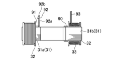
- the stator 30 includes a stator core 31.
- the stator core 31 includes a cylindrical core portion 31a and twelve tooth portions 31b arranged to extend radially outward from a circumference of the core portion 31a in a radial manner.
- the stator 30 further includes twelve coils 33. Each of the coils 33 is defined by winding a conductor wire around a separate one of the tooth portions 31b with an intervening insulator 32, which has an insulation property.
- Four screwing portions 34 are defined in an inner circumferential wall of the core portion 31a. The screwing portions 34 are used for the screws to be inserted into the fourth screw holes 72 defined in the small diameter portion 70b of the shaft support portion 70.
- the screwing portions 34 are arranged at substantially regular intervals in the circumferential direction.
- stator 30 is attached to the small diameter portion 70b, which has a relatively small outside diameter, of the shaft support portion 70, a reduction in the diameter of the stator 30 is achieved with the same performance of the motor 1.
- This makes it possible to also reduce the diameter of the rotor 20, which leads to a reduction in the total volume of the magnet 22 and hence a reduction in a material cost, and makes it possible to reduce the radial dimension of the motor 1.
- the insulator 32 is an injection molded article made of a resin, and includes an upper end wall portion 90 arranged to cover an upper end surface of the core portion 31a.
- a cylindrical restricting wall 91 is arranged to extend along a periphery of the upper end wall portion 90, and stand in the axial direction.
- four coming-off preventing portions 92 are arranged radially inward of the restricting wall 91 on the upper end wall portion 90.
- the coming-off preventing portions 92 are arranged at substantially regular intervals in the circumferential direction.
- Each of the coming-off preventing portions 92 includes an arm portion 92a and a hook portion 92b.
- the arm portion 92a is arranged to extend in the axial direction and is flexibly deformable.
- the hook portion 92b is arranged on a top of the arm portion 92a. Referring to Fig. 7, the hook portion 92b is arranged to project radially outward, and a lower end of the hook portion 92b is arranged to be located above an upper end of the restricting wall 91.
- the coming-off preventing portions 92 serve to improve workability in an assembling operation. Furthermore, the restricting wall 91 serves also as a restricting portion to prevent a conductor wire from any coil 33 from protruding toward the core portion 31a.
- Wire ends 93 i.e., end portions of six conductor wires, are drawn from predetermined locations of the stator 30 to be connected to the circuit board 40. In more detail, two conductor wires arranged in proximity to each other are drawn upward from each of three different locations.
- Fig. 8 illustrates the circuit board 40.
- the circuit board 40 has a capability to supply currents from an external source to the stator 30 to control rotation of the rotor 20.
- Electronic components such as FETs 41 (i.e., transistors), which are switching elements, a capacitor 42, a Hall IC 43, and so on, are mounted on the circuit board 40.
- FETs 41 i.e., transistors
- an electrical circuit made up of these electronic components interconnected is defined on a surface of the circuit board 40.
- the circuit board 40 is arranged in the shape of a disc in accordance with the interior shape of the bracket 50.
- the circuit board 40 includes an opening portion 44 defined in a central portion thereof to have the shaft support portion 70 inserted therethrough.
- recessed portions 45 recessed radially outward are defined in a periphery of the opening portion 44 at four different locations corresponding to those of the coming-off preventing portions 92 of the stator 30.
- the recessed portions 45 are arranged at substantially regular intervals in the circumferential direction.
- the capacitor 42 which is an electronic component that generates a large amount of heat and has a relatively large size, is arranged at a predetermined location on an upper surface of the circuit board 40.
- a space between the end wall portion 52 and the shoulder wall portion 51b inside the bracket 50 is used to accommodate the capacitor 42, and an inner surface of the bracket 50 and the capacitor 42 are arranged in proximity to each other.
- the capacitor 42 is thereby efficiently accommodated inside the bracket 50, facilitating a reduction in the size of the motor 1. Moreover, because heat is easily radiated through the bracket 50, an improvement in cooling capacity is also achieved.
- Each of the FETs 41 is a heat-radiating electronic component that generates an enormous amount of heat.
- the FETs 41 are arranged at six different locations along a circumference of the circuit board 40 in an outer periphery portion of the circuit board 40, and arranged opposite the shoulder wall portion 51b of the bracket 50.
- each of the FETs 41 includes a thin-film heat radiating portion 41a arranged on the upper surface of the circuit board 40, an FET body 41b arranged on a lower surface of the circuit board 40, and nine heat transmission channels 41c arranged to extend through the circuit board 40 to join the heat radiating portion 41a and the FET body 41b to each other.
- the FET body 41b is a body of a transistor which is the shape of a block.
- the heat radiating portion 41a and the heat transmission channels 41c are excellent in thermal conductivity.
- the heat radiating portion 41a is arranged on the upper surface of the circuit board 40, while the FET body 41b, i.e., the body of the transistor, is arranged on the lower surface of the circuit board 40.
- the Hall IC 43 has a capability to detect a rotation angle of the rotor 20 and so on based on a magnetic change of the rotor 20, and is arranged on the lower surface of the circuit board 40.
- the Hall IC 43 is arranged opposite the magnet 22 and in the vicinity of an outer circumferential edge of the rotor 20 on a side closer to the circuit board 40.
- the FETs 41 are arranged radially outward of the Hall IC 43. This is because the rotor 20 might otherwise come into contact with any FET body 41b when arranged in proximity to the circuit board 40, and because the Hall IC 43 has to be free from a thermal influence.
- the FETs 41 are arranged in a space radially outward of the rotor 20 which is obtained thanks to the aforementioned reduction in the diameter of the rotor 20, and the FETs 41 are arranged on the outer periphery portion of the circuit board 40, which is opposite to the shoulder wall portion 51b. As a result, a reduction in the axial dimension of the motor 1 is also achieved.
- second screw holes 47 are defined at four different locations in the outer periphery portion of the circuit board 40.
- the second screw holes 47 are used for the screws to be inserted into the shoulder wall portion 51b of the bracket 50.
- the circuit board 40 is fastened to the shoulder wall portion 51b with the screws inserted through the second screw holes 47 into the second fastening holes 58. Because of the protruding portions, a gap is defined between the circuit board 40 and an inner surface of the shoulder wall portion 51b. Insulation is thereby ensured between the circuit board 40 and the bracket 50.
- the heat radiating portion 41a is arranged in surface contact with the inner surface of the shoulder wall portion 51b through a heat transmitting member 46, which is an insulating member excellent in thermal conductivity. Accordingly, heat generated from each FET 41 is stably discharged to the bracket 50 through the heat transmitting member 46.
- a heat transmitting member 46 which is an insulating member excellent in thermal conductivity. Accordingly, heat generated from each FET 41 is stably discharged to the bracket 50 through the heat transmitting member 46.
- silicone grease, a heat radiation sheet, or the like for example, may be used as the heat transmitting member 46.
- the heat transmitting member 46 may be in any form as long as it is excellent in thermal conductivity and insulating performance.
- the heat transmitting member 46 may be, for example, in a liquid state, in a gel state, in the shape of a sheet, or the like.
- the FET body portion 41b is arranged on the lower surface of the circuit board 40. Therefore, compared with the case where the FET body portion 41b is arranged on the upper surface of the circuit board 40, positioning of the circuit board 40 can be achieved with greater precision regardless of the size of the FET body portion 41b or precision in the positioning of the FET body portion 41b. This makes it possible to improve precision in the distance between the Hall IC 43 and the magnet 22, thereby improving precision in detection of the rotation angle.
- lead wire attaching portions 48 are arranged in proximity to one another in a portion of the circuit board 40 between two of the second screw holes 47.
- Four of the lead wires 48a connected to an electronic device placed outside the motor 1 are connected to the lead wire attaching portions 48, respectively.
- the partition wall 64 of the base plate 60 is positioned under the lead wire attaching portions 48.
- the lead wire attaching portions 48 are arranged opposite the swell portion 54 of the bracket 50 so that a contact between any lead wire 48a and the bracket 50 may be securely avoided.
- Each of the lead wires 48a is drawn out of the motor 1 with an intermediate portion thereof secured to the base plate 60 so that the lead wire 48a may not act on any interior portion of the bracket 50 even if the lead wire 48a is pulled from the outside.
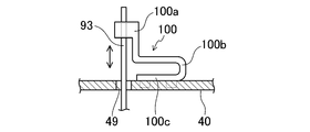
- insert holes 49 and connection terminals 100 are arranged at three different locations in or on the upper surface of the circuit board 40. At each of the three locations, one of the insert holes 49 and one of the connection terminals 100 are arranged in proximity to each other. The wire ends 93 are inserted through the insert holes 49 and connected to the connection terminals 100.
- each of the connection terminals 100 is a pressed article made from a metal sheet, and includes a connection portion 100a, an elastic portion 100b, and a base portion 100c.
- the connection portion 100a is in the shape of the letter "C" in a cross-section, and is arranged to embrace and thereby secure the wire ends 93.
- the elastic portion 100b is continuous with the connection portion 100a and capable of elastic deformation.
- the base portion 100c is continuous with the elastic portion 100b, and is arranged to be attached to the circuit board 40.
- the connection portion 100a is capable of shifting in the axial direction, which is perpendicular to the circuit board 40, in accordance with bending deformation of the elastic portion 100b. Therefore, a slight axial displacement of the wire ends 93 secured by welding or the like would not cause the connection terminal 100 to apply a significant load onto the circuit board 40.
- the coming-off preventing portions 92 of the stator 30 are fitted into the recessed portions 45 of the circuit board 40, and the circuit board 40 is temporarily secured to the stator 30 as illustrated in Fig. 13.
- This temporary securing fixedly positions the circuit board 40 in the circumferential direction relative to the stator 30, while permitting the circuit board 40 to move slightly in the axial direction relative to the stator 30.
- the wire ends 93 are positioned under the respective insert holes 49 of the circuit board 40 so that the wire ends 93 can be easily drawn through the insert holes 49 upward from the upper surface of the circuit board 40.
- connection portion 100a of a corresponding one of the connection terminals 100 Two of the wire ends 93 are drawn through each of the insert holes 49 in this manner, and fixed to the connection portion 100a of a corresponding one of the connection terminals 100 through welding or the like. If the stator 30 is placed on a lower side relative to the circuit board 40, the circuit board 40 is supported on the restricting wall 91 to facilitate this process of fixing. Even if the circuit board 40 is displaced in the axial direction relative to the stator 30 after the fixing process, the elastic deformation of the connection terminal 100 will prevent an excessive load from being applied onto the circuit board 40.
- the lead wires 48a are connected to the circuit board 40 prior to, simultaneously with, or subsequent to the above fixing process.
- the stator 30 and so on are fitted to the bracket 50.
- the temporary securing of the circuit board 40 to the stator 30 improves workability here.
- the stator 30 and so on are placed inside the bracket 50, firstly with the circuit board 40, and the screws are inserted into the second screw holes 47 and the second fastening holes 58 to fix the circuit board 40 to the bracket 50.
- the screws are inserted into the screwing portions 34 and the fourth screw holes 72 to fix the stator 30 to the shaft support portion 70.
- the restricting wall 91 contributes to preventing a screwdriver or the like from coming into contact with any coil 33. Note that, prior to this assembling process, press fitting of the first bearing 81 to the bracket 50, attachment of the heat transmitting members 46 to the inner surface of the shoulder wall portion 51b, and so on are carried out.
- the wave washer 83 is placed inside the second bearing hole, and the second bearing 82 is thereafter inserted into the second bearing hole to be placed on the wave washer 83.
- the shaft 10 with the rotor 20 fixed thereto is then inserted through the shaft support portion 70 until the top portion of the shaft 10 projects from the bracket 50.
- the lock ring 11 is fitted into a fitting groove defined in the base portion of the top portion of the shaft 10 to fit the shaft 10 and so on to the bracket 50 and so on.
- motors according to preferred embodiments of the present invention are not limited to the motor 1 according to the above-described preferred embodiment and the like, but include a variety of other motors having different structures.
- the bracket 50 may be a die casting made of aluminum, for example.
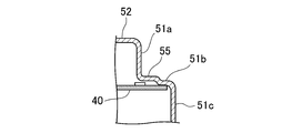
- a flat portion 51b in the shape of a circular arc and extending in the circumferential direction perpendicularly to the rotation axis A may be defined in an inside wall surface of the bracket 50.
- the FETs 41 are arranged opposite the flat portion 51b, and a portion of the circuit board 40 is fixed to the flat portion 51b.
- An insulation sheet or the like that is excellent in thermal conductivity may be arranged between the flat portion 51b and the circuit board 40 in order to improve cooling capacity of the circuit board 40. Note that members and portions having equivalent functions are denoted by the same reference characters, and redundant descriptions thereof are omitted.
- raised portions 55 may be defined in the shoulder wall portion 51b.
- the circuit board 40 is arranged in surface contact with the shoulder wall portion 51b with the raised portions 55 arranged opposite the FETs 41 and other electronic components.
- the circuit board 40 is thereby fixed with a large area of the outer periphery portion of the circuit board 40 arranged in close contact with the inner surface of the shoulder wall portion 51b. Accordingly, the circuit board 40 is fixed to the bracket 50 with stability without undergoing a bending deformation, and a clearance space between the circuit board 40 and the bracket 50 can be defined with high precision. Thus, contact of each FET 41 with the bracket 50 through the heat transmitting member 46, and separation of the other electronic components from the bracket 50, are ensured with stability.
- An intervening material of a predetermined thickness may be arranged between the inner surface of the shoulder wall portion 51b and the outer periphery portion of the circuit board 40 to define a gap between the FETs 41 and the bracket 50. While the shaft support portion 70 may be arranged to decrease in the outside diameter in a stepwise manner toward the top as in the above-described preferred embodiment, the shaft support portion 70 may be arranged to gradually decrease in the outside diameter in a continuous manner toward the top.
- motor 10 shaft 20 rotor 30 stator 40 circuit board 41 FETs 50 bracket 51 circumferential wall portion 51b shoulder wall portion 52 end wall portion 53 flange portion 60 base plate 70 shaft support portion 81 first bearing 82 second bearing A rotation axis
Landscapes
- Engineering & Computer Science (AREA)
- Power Engineering (AREA)
- Transportation (AREA)
- Mechanical Engineering (AREA)
- Microelectronics & Electronic Packaging (AREA)
- Motor Or Generator Frames (AREA)
- Brushless Motors (AREA)
Abstract
Description
Next, referring to Figs. 13 and 14, a method of assembling the
10 shaft
20 rotor
30 stator
40 circuit board
41 FETs
50 bracket
51 circumferential wall portion
51b shoulder wall portion
52 end wall portion
53 flange portion
60 base plate
70 shaft support portion
81 first bearing
82 second bearing
A rotation axis
Claims (5)
- A motor comprising:
a shaft arranged to rotate about a rotation axis;
a rotor fixed to an end portion of the shaft;
a stator arranged inside the rotor;
a bracket arranged to accommodate the shaft, the rotor, and the stator, and including a circumferential wall portion arranged to surround circumferences of the shaft, the rotor, and the stator, and an end wall portion arranged to close one end of the circumferential wall portion; and
a base plate fitted to the bracket and arranged to close an opposite end of the circumferential wall portion; wherein
a tubular shaft support portion is arranged on an inside of the end wall portion to extend in a direction of the base plate;
the shaft support portion is arranged to rotatably support the shaft through a pair of bearings;
the pair of bearings are made up of a first bearing arranged on a base portion of the shaft support portion, and a second bearing arranged on a top portion of the shaft support portion, the second bearing having a diameter smaller than that of the first bearing;
the shaft support portion is arranged to have a smaller outside diameter at the top portion than at the base portion;
the motor further comprises a circuit board including an opening portion defined in a central portion thereof, and having electronic components mounted thereon, the electronic components including a switching element;
the circuit board is accommodated in the bracket with the shaft support portion inserted in the opening portion;
an inner surface of the circumferential wall portion includes a flat portion arranged to extend in a circumferential direction substantially perpendicularly to the rotation axis;
the switching element is arranged on a predetermined portion of a periphery portion of the circuit board, the predetermined portion being radially outward of the rotor and opposite the flat portion; and
the circuit board is fixed to the bracket with the switching element arranged in contact with the flat portion through an insulating heat transmitting member. - The motor according to claim 1, wherein
the switching element is a transistor; and
the transistor includes:
a heat radiating portion arranged on a surface of the circuit board on a side closer to the flat portion; and
a transistor body arranged on a surface of the circuit board on an opposite side, and integrally connected to the heat radiating portion through a heat transmission channel. - The motor according to claim 2, wherein
the electronic components include a capacitor; and
the capacitor is arranged in a space between the flat portion and the end wall portion. - The motor according to any one of claims 1 to 3, wherein
the circuit board includes recessed portions defined at a plurality of locations in a periphery of the opening portion and recessed radially outward;
the stator includes:
a plurality of coming-off preventing portions each of which includes an arm portion arranged to extend in an axial direction and to be flexibly deformable, and a hook portion arranged on a top of the arm portion and to be engaged with a corresponding one of the recessed portions; and
a restricting portion arranged to temporarily secure the circuit board such that the circuit board is movable in the axial direction by having the circuit board placed between the restricting portion and the plurality of coming-off preventing portions; and
the stator is fixed to the shaft support portion. - The motor according to claim 4, wherein
the circuit board includes a connection terminal to which a conductor wire drawn from the stator is connected; and
the connection terminal includes:
a connection portion to which the conductor wire is fixed;
an elastic portion arranged to be continuous with the connection portion and elastically deformable in the axial direction; and
a base portion arranged to be continuous with the elastic portion and attached to the circuit board.
Priority Applications (2)
| Application Number | Priority Date | Filing Date | Title |
|---|---|---|---|
| CN2011900006258U CN203166659U (en) | 2010-08-20 | 2011-07-28 | Motor |
| DE112011102756T DE112011102756T5 (en) | 2010-08-20 | 2011-07-28 | engine |
Applications Claiming Priority (2)
| Application Number | Priority Date | Filing Date | Title |
|---|---|---|---|
| JP2010185411A JP2013153544A (en) | 2010-08-20 | 2010-08-20 | Motor |
| JP2010-185411 | 2010-08-20 |
Publications (1)
| Publication Number | Publication Date |
|---|---|
| WO2012023245A1 true WO2012023245A1 (en) | 2012-02-23 |
Family
ID=45604916
Family Applications (1)
| Application Number | Title | Priority Date | Filing Date |
|---|---|---|---|
| PCT/JP2011/004298 WO2012023245A1 (en) | 2010-08-20 | 2011-07-28 | Motor |
Country Status (4)
| Country | Link |
|---|---|
| JP (1) | JP2013153544A (en) |
| CN (1) | CN203166659U (en) |
| DE (1) | DE112011102756T5 (en) |
| WO (1) | WO2012023245A1 (en) |
Cited By (7)
| Publication number | Priority date | Publication date | Assignee | Title |
|---|---|---|---|---|
| EP2869438A4 (en) * | 2012-06-29 | 2016-03-09 | Oriental Motor Co Ltd | Attachment method and attachment structure for brushless motor sensor substrate |
| WO2016198213A1 (en) * | 2015-06-08 | 2016-12-15 | Robert Bosch Gmbh | Electrically commutated electric motor and convenience drive comprising an electric motor |
| WO2017081415A1 (en) * | 2015-11-13 | 2017-05-18 | Valeo Systemes Thermiques | Module for controlling the power supply of an electric motor |
| CN109494913A (en) * | 2017-09-13 | 2019-03-19 | 信浓绢糸株式会社 | Motor |
| EP3456978A1 (en) * | 2017-09-13 | 2019-03-20 | Shinano Kenshi Co., Ltd. | Blower device |
| EP3496248A4 (en) * | 2016-08-05 | 2020-04-08 | Nidec Corporation | Motor |
| US11063496B2 (en) | 2016-08-05 | 2021-07-13 | Nidec Corporation | Vertical motor with resin bracket and cover having circuit board with wireless communication unit |
Families Citing this family (8)
| Publication number | Priority date | Publication date | Assignee | Title |
|---|---|---|---|---|
| JP6270510B2 (en) * | 2014-01-30 | 2018-01-31 | 東京パーツ工業株式会社 | DC brushless motor |
| JP2016226179A (en) * | 2015-05-29 | 2016-12-28 | 日本電産株式会社 | motor |
| CN106059147B (en) * | 2016-07-28 | 2018-07-24 | 宁波市兴宇电机制造有限公司 | A kind of Air Condition Compressor for Electric Vehicle driving DC brushless motor |
| JP2020005461A (en) * | 2018-06-29 | 2020-01-09 | 日本電産株式会社 | motor |
| EP3656503B1 (en) * | 2018-10-29 | 2023-10-18 | Guido Valentini | Hand-held and hand-guided random orbital polishing or sanding power tool |
| US11973374B2 (en) | 2019-04-24 | 2024-04-30 | Black & Decker Inc. | Outer rotor brushless motor having an axial fan |
| JP7478010B2 (en) * | 2020-03-31 | 2024-05-02 | 平田機工株式会社 | Rotating Electric Machine |
| JP2022069124A (en) * | 2020-10-23 | 2022-05-11 | ミネベアミツミ株式会社 | motor |
Citations (2)
| Publication number | Priority date | Publication date | Assignee | Title |
|---|---|---|---|---|
| JP2004096905A (en) * | 2002-08-30 | 2004-03-25 | Nidec Shibaura Corp | Motor |
| JP2006180643A (en) * | 2004-12-24 | 2006-07-06 | Aichi Electric Co Ltd | Motor |
Family Cites Families (3)
| Publication number | Priority date | Publication date | Assignee | Title |
|---|---|---|---|---|
| JP4512803B2 (en) | 2008-10-15 | 2010-07-28 | シナノケンシ株式会社 | Brushless motor |
| JP2010098816A (en) | 2008-10-15 | 2010-04-30 | Shinano Kenshi Co Ltd | Blower motor |
| JP2010098817A (en) | 2008-10-15 | 2010-04-30 | Shinano Kenshi Co Ltd | Outer-rotor brushless motor |
-
2010
- 2010-08-20 JP JP2010185411A patent/JP2013153544A/en not_active Withdrawn
-
2011
- 2011-07-28 CN CN2011900006258U patent/CN203166659U/en not_active Expired - Lifetime
- 2011-07-28 DE DE112011102756T patent/DE112011102756T5/en not_active Withdrawn
- 2011-07-28 WO PCT/JP2011/004298 patent/WO2012023245A1/en active Application Filing
Patent Citations (2)
| Publication number | Priority date | Publication date | Assignee | Title |
|---|---|---|---|---|
| JP2004096905A (en) * | 2002-08-30 | 2004-03-25 | Nidec Shibaura Corp | Motor |
| JP2006180643A (en) * | 2004-12-24 | 2006-07-06 | Aichi Electric Co Ltd | Motor |
Cited By (13)
| Publication number | Priority date | Publication date | Assignee | Title |
|---|---|---|---|---|
| EP2869438A4 (en) * | 2012-06-29 | 2016-03-09 | Oriental Motor Co Ltd | Attachment method and attachment structure for brushless motor sensor substrate |
| US9350215B2 (en) | 2012-06-29 | 2016-05-24 | Oriental Motor Co., Ltd. | Method and structure for mounting sensor substrate of brushless motor |
| WO2016198213A1 (en) * | 2015-06-08 | 2016-12-15 | Robert Bosch Gmbh | Electrically commutated electric motor and convenience drive comprising an electric motor |
| WO2017081415A1 (en) * | 2015-11-13 | 2017-05-18 | Valeo Systemes Thermiques | Module for controlling the power supply of an electric motor |
| FR3043858A1 (en) * | 2015-11-13 | 2017-05-19 | Valeo Systemes Thermiques | POWER CONTROL MODULE OF AN ELECTRIC MOTOR |
| CN108604846A (en) * | 2015-11-13 | 2018-09-28 | 法雷奥热系统公司 | Module for the power supply for controlling electric notor |
| CN108604846B (en) * | 2015-11-13 | 2020-10-09 | 法雷奥热系统公司 | Module for controlling the power supply of an electric motor |
| US10630149B2 (en) | 2015-11-13 | 2020-04-21 | Valeo Systemes Thermiques | Module for controlling the power supply of an electric motor |
| EP3496248A4 (en) * | 2016-08-05 | 2020-04-08 | Nidec Corporation | Motor |
| US11063496B2 (en) | 2016-08-05 | 2021-07-13 | Nidec Corporation | Vertical motor with resin bracket and cover having circuit board with wireless communication unit |
| EP3457537A1 (en) * | 2017-09-13 | 2019-03-20 | Shinano Kenshi Co., Ltd. | Motor |
| EP3456978A1 (en) * | 2017-09-13 | 2019-03-20 | Shinano Kenshi Co., Ltd. | Blower device |
| CN109494913A (en) * | 2017-09-13 | 2019-03-19 | 信浓绢糸株式会社 | Motor |
Also Published As
| Publication number | Publication date |
|---|---|
| DE112011102756T5 (en) | 2013-09-19 |
| CN203166659U (en) | 2013-08-28 |
| JP2013153544A (en) | 2013-08-08 |
Similar Documents
| Publication | Publication Date | Title |
|---|---|---|
| WO2012023245A1 (en) | Motor | |
| US9893586B2 (en) | Driver apparatus provided with a motor and a control unit | |
| JP6509702B2 (en) | An electronically commutated DC motor particularly suitable for oil pumps | |
| US9882446B2 (en) | Motor | |
| US20160248292A1 (en) | Electronic control apparatus, motor control apparatus and electric fluid pump | |
| US10008909B2 (en) | Motor driving control device for vehicle | |
| US5883450A (en) | Alternator, in particular for a motor vehicle including an improved arrangement of rectifier diodes | |
| US20190283798A1 (en) | Motor and electric power steering device | |
| WO2017033917A1 (en) | Motor | |
| US20100096938A1 (en) | Blower motor | |
| CN209982207U (en) | Stator unit and electric actuator | |
| JP2015106970A (en) | Drive device | |
| JP6248433B2 (en) | motor | |
| US20100090554A1 (en) | Outer-rotor brushless motor | |
| US20170179803A1 (en) | Motor | |
| US9949386B2 (en) | Motor device | |
| US9960653B2 (en) | Driving device having sealing member with first and second annular protrusions | |
| JP6648569B2 (en) | Motor drive control device for vehicle | |
| KR102094085B1 (en) | Hollow Shaft Motor | |
| JP2013115923A (en) | Brushless motor | |
| JP6229331B2 (en) | motor | |
| JP2014099961A (en) | Electric motor and ventilation fan | |
| JP2013198310A (en) | Electric connection structure, sealing apparatus, and inverter integrated motor | |
| JP6717258B2 (en) | Inverter integrated rotating electrical machine | |
| JP2013219914A (en) | Motor |
Legal Events
| Date | Code | Title | Description |
|---|---|---|---|
| WWE | Wipo information: entry into national phase |
Ref document number: 201190000625.8 Country of ref document: CN |
|
| 121 | Ep: the epo has been informed by wipo that ep was designated in this application |
Ref document number: 11817896 Country of ref document: EP Kind code of ref document: A1 |
|
| WWE | Wipo information: entry into national phase |
Ref document number: 1120111027567 Country of ref document: DE Ref document number: 112011102756 Country of ref document: DE |
|
| NENP | Non-entry into the national phase |
Ref country code: JP |
|
| 122 | Ep: pct application non-entry in european phase |
Ref document number: 11817896 Country of ref document: EP Kind code of ref document: A1 |