JP7478010B2 - Rotating Electric Machine - Google Patents
Rotating Electric Machine Download PDFInfo
- Publication number
- JP7478010B2 JP7478010B2 JP2020062082A JP2020062082A JP7478010B2 JP 7478010 B2 JP7478010 B2 JP 7478010B2 JP 2020062082 A JP2020062082 A JP 2020062082A JP 2020062082 A JP2020062082 A JP 2020062082A JP 7478010 B2 JP7478010 B2 JP 7478010B2
- Authority
- JP
- Japan
- Prior art keywords
- stator
- circuit board
- case
- rotating electric
- electric machine
- Prior art date
- Legal status (The legal status is an assumption and is not a legal conclusion. Google has not performed a legal analysis and makes no representation as to the accuracy of the status listed.)
- Active
Links
- 229920005989 resin Polymers 0.000 claims description 92
- 239000011347 resin Substances 0.000 claims description 92
- 239000012212 insulator Substances 0.000 claims description 70
- 238000004804 winding Methods 0.000 claims description 44
- 230000005669 field effect Effects 0.000 claims description 24
- 230000002093 peripheral effect Effects 0.000 description 30
- 230000000694 effects Effects 0.000 description 17
- 239000000463 material Substances 0.000 description 12
- 230000004323 axial length Effects 0.000 description 11
- 238000009413 insulation Methods 0.000 description 10
- 238000003780 insertion Methods 0.000 description 8
- 230000037431 insertion Effects 0.000 description 8
- 238000000034 method Methods 0.000 description 8
- 238000010586 diagram Methods 0.000 description 7
- 229910052782 aluminium Inorganic materials 0.000 description 6
- XAGFODPZIPBFFR-UHFFFAOYSA-N aluminium Chemical compound [Al] XAGFODPZIPBFFR-UHFFFAOYSA-N 0.000 description 6
- 238000001514 detection method Methods 0.000 description 6
- 230000004048 modification Effects 0.000 description 6
- 238000012986 modification Methods 0.000 description 6
- 229910052751 metal Inorganic materials 0.000 description 5
- 239000002184 metal Substances 0.000 description 5
- 230000020169 heat generation Effects 0.000 description 4
- 239000000758 substrate Substances 0.000 description 4
- 229920006231 aramid fiber Polymers 0.000 description 3
- 238000004891 communication Methods 0.000 description 3
- 230000017525 heat dissipation Effects 0.000 description 3
- WABPQHHGFIMREM-UHFFFAOYSA-N lead(0) Chemical compound [Pb] WABPQHHGFIMREM-UHFFFAOYSA-N 0.000 description 3
- XEEYBQQBJWHFJM-UHFFFAOYSA-N Iron Chemical compound [Fe] XEEYBQQBJWHFJM-UHFFFAOYSA-N 0.000 description 2
- QVGXLLKOCUKJST-UHFFFAOYSA-N atomic oxygen Chemical compound [O] QVGXLLKOCUKJST-UHFFFAOYSA-N 0.000 description 2
- 229910052760 oxygen Inorganic materials 0.000 description 2
- 239000001301 oxygen Substances 0.000 description 2
- 229920001343 polytetrafluoroethylene Polymers 0.000 description 2
- 239000004810 polytetrafluoroethylene Substances 0.000 description 2
- 238000002360 preparation method Methods 0.000 description 2
- 230000008569 process Effects 0.000 description 2
- 229910000831 Steel Inorganic materials 0.000 description 1
- 230000009471 action Effects 0.000 description 1
- 239000000853 adhesive Substances 0.000 description 1
- 230000001070 adhesive effect Effects 0.000 description 1
- 230000000903 blocking effect Effects 0.000 description 1
- 230000008859 change Effects 0.000 description 1
- 230000006866 deterioration Effects 0.000 description 1
- 230000002708 enhancing effect Effects 0.000 description 1
- 239000003822 epoxy resin Substances 0.000 description 1
- 230000004907 flux Effects 0.000 description 1
- 230000006872 improvement Effects 0.000 description 1
- 238000009434 installation Methods 0.000 description 1
- 239000011810 insulating material Substances 0.000 description 1
- 229910052742 iron Inorganic materials 0.000 description 1
- 230000007257 malfunction Effects 0.000 description 1
- 238000004519 manufacturing process Methods 0.000 description 1
- 238000005259 measurement Methods 0.000 description 1
- 238000000691 measurement method Methods 0.000 description 1
- 239000007769 metal material Substances 0.000 description 1
- 238000000465 moulding Methods 0.000 description 1
- 230000003287 optical effect Effects 0.000 description 1
- 229920000647 polyepoxide Polymers 0.000 description 1
- 229920001296 polysiloxane Polymers 0.000 description 1
- -1 polytetrafluoroethylene Polymers 0.000 description 1
- 238000007789 sealing Methods 0.000 description 1
- 230000035945 sensitivity Effects 0.000 description 1
- 229910000679 solder Inorganic materials 0.000 description 1
- 238000005476 soldering Methods 0.000 description 1
- 239000010959 steel Substances 0.000 description 1
- 229920001187 thermosetting polymer Polymers 0.000 description 1
Images


Classifications
-
- H—ELECTRICITY
- H02—GENERATION; CONVERSION OR DISTRIBUTION OF ELECTRIC POWER
- H02K—DYNAMO-ELECTRIC MACHINES
- H02K11/00—Structural association of dynamo-electric machines with electric components or with devices for shielding, monitoring or protection
- H02K11/20—Structural association of dynamo-electric machines with electric components or with devices for shielding, monitoring or protection for measuring, monitoring, testing, protecting or switching
- H02K11/25—Devices for sensing temperature, or actuated thereby
-
- H—ELECTRICITY
- H02—GENERATION; CONVERSION OR DISTRIBUTION OF ELECTRIC POWER
- H02K—DYNAMO-ELECTRIC MACHINES
- H02K11/00—Structural association of dynamo-electric machines with electric components or with devices for shielding, monitoring or protection
- H02K11/30—Structural association with control circuits or drive circuits
- H02K11/33—Drive circuits, e.g. power electronics
-
- H—ELECTRICITY
- H02—GENERATION; CONVERSION OR DISTRIBUTION OF ELECTRIC POWER
- H02K—DYNAMO-ELECTRIC MACHINES
- H02K11/00—Structural association of dynamo-electric machines with electric components or with devices for shielding, monitoring or protection
- H02K11/30—Structural association with control circuits or drive circuits
-
- H—ELECTRICITY
- H02—GENERATION; CONVERSION OR DISTRIBUTION OF ELECTRIC POWER
- H02K—DYNAMO-ELECTRIC MACHINES
- H02K3/00—Details of windings
- H02K3/46—Fastening of windings on the stator or rotor structure
- H02K3/52—Fastening salient pole windings or connections thereto
- H02K3/521—Fastening salient pole windings or connections thereto applicable to stators only
- H02K3/522—Fastening salient pole windings or connections thereto applicable to stators only for generally annular cores with salient poles
-
- H—ELECTRICITY
- H02—GENERATION; CONVERSION OR DISTRIBUTION OF ELECTRIC POWER
- H02K—DYNAMO-ELECTRIC MACHINES
- H02K11/00—Structural association of dynamo-electric machines with electric components or with devices for shielding, monitoring or protection
- H02K11/20—Structural association of dynamo-electric machines with electric components or with devices for shielding, monitoring or protection for measuring, monitoring, testing, protecting or switching
- H02K11/21—Devices for sensing speed or position, or actuated thereby
- H02K11/215—Magnetic effect devices, e.g. Hall-effect or magneto-resistive elements
-
- H—ELECTRICITY
- H02—GENERATION; CONVERSION OR DISTRIBUTION OF ELECTRIC POWER
- H02K—DYNAMO-ELECTRIC MACHINES
- H02K11/00—Structural association of dynamo-electric machines with electric components or with devices for shielding, monitoring or protection
- H02K11/20—Structural association of dynamo-electric machines with electric components or with devices for shielding, monitoring or protection for measuring, monitoring, testing, protecting or switching
- H02K11/21—Devices for sensing speed or position, or actuated thereby
- H02K11/22—Optical devices
Landscapes
- Engineering & Computer Science (AREA)
- Power Engineering (AREA)
- Microelectronics & Electronic Packaging (AREA)
- Permanent Magnet Type Synchronous Machine (AREA)
- Iron Core Of Rotating Electric Machines (AREA)
- Connection Of Motors, Electrical Generators, Mechanical Devices, And The Like (AREA)
Description
本発明は、回転電機に関する。 The present invention relates to a rotating electric machine.
従来、回転電機において、インナロータ型のブラシレスDCモータが知られている(例えば、特許文献1及び2参照)。
例えば、特許文献1には、モータのケース内に樹脂が注入された構造が開示されている。樹脂は、ロータが挿入される空間を中心部分に残し、ステータとケースとの間に充填されている。
例えば、特許文献2には、モータの温度を検出し得る温度センサを備えた構造が開示されている。温度センサは、ステータコアに巻線を施してなるコイル内に埋め込まれている。
2. Description of the Related Art Inner rotor type brushless DC motors have been known as rotating electrical machines (see, for example, Japanese Patent Application Laid-Open No. 2003-233633 and Japanese Patent Application Laid-Open No. 2003-233634).
For example,
For example,
しかし、温度センサを用いることによる完全性を向上し、モータの発熱による不具合を抑制する上で改善の余地があった。 However, there was room for improvement in terms of improving the integrity of the temperature sensor and reducing malfunctions caused by heat generated by the motor.
そこで本発明は、温度センサを用いることにより、回転電機の発熱による不具合を抑制することを目的とする。 Therefore, the present invention aims to suppress problems caused by heat generation in rotating electrical machines by using a temperature sensor.
上記課題の解決手段として、本発明の態様は以下の構成を有する。
(1)本発明の態様に係る回転電機は、筒状のステータと、前記ステータの内部空間に配置されるロータと、前記ステータを収容する筒状又は有底筒状のケースと、前記ケースの一方側の開口端に取り付けられるエンドカバーと、温度センサと、を備え、前記ステータは、前記ステータの中心に向けて突出する複数の突出部を有するステータコアと、前記ステータコアに装着されるインシュレータと、前記複数の突出部のそれぞれに前記インシュレータを介して巻線を巻回してなるコイルと、を備え、前記温度センサは、前記ステータの前記エンドカバーの側において、周方向に隣り合う2つの前記コイルにおける前記巻線の屈曲部の間に配置され、前記温度センサは、周方向に隣り合う2つの前記コイルのそれぞれの巻線の屈曲部に当接しており、前記巻線の屈曲部と前記温度センサとの当接部の周囲に樹脂が充填されている。
As a means for solving the above problems, the present invention has the following configuration.
(1) A rotating electric machine according to one aspect of the present invention comprises a cylindrical stator, a rotor disposed in an internal space of the stator, a cylindrical or bottomed cylindrical case that houses the stator, an end cover attached to one open end of the case, and a temperature sensor, wherein the stator comprises a stator core having a plurality of protrusions that protrude toward a center of the stator, an insulator attached to the stator core, and a coil formed by winding a winding around each of the plurality of protrusions via the insulator, and the temperature sensor is disposed between the bent portions of the windings of two circumferentially adjacent coils on the end cover side of the stator , the temperature sensor abutting the bent portions of the windings of each of the two circumferentially adjacent coils, and resin is filled around the abutment portion between the bent portions of the windings and the temperature sensor .
(2)上記(1)に記載の回転電機では、前記回転電機の駆動を制御する回路基板を更に備え、前記回路基板は、前記ケースの軸方向外端よりも内側に配置され、かつ、前記ステータと前記エンドカバーとの間に配置されていてもよい。 ( 2 ) The rotating electric machine described in (1) above may further include a circuit board that controls the drive of the rotating electric machine, and the circuit board may be positioned inside the axial outer end of the case and between the stator and the end cover.
(3)上記(2)に記載の回転電機では、前記インシュレータは、前記回路基板の前記ステータの側の面に当接する当接部を有していてもよい。 ( 3 ) In the rotating electric machine described in ( 2 ) above, the insulator may have a contact portion that contacts a surface of the circuit board on the side of the stator.
(4)上記(2)又は(3)に記載の回転電機では、前記回路基板は、周方向に間隔をあけて配置される複数の係合部を有し、前記インシュレータは、前記複数の係合部のそれぞれを通じて前記回路基板に係合する係合部を有してもよい。 ( 4 ) In the rotating electric machine described in ( 2 ) or ( 3 ) above, the circuit board may have a plurality of engaging portions arranged at intervals in the circumferential direction, and the insulator may have an engaging portion that engages with the circuit board through each of the plurality of engaging portions.
(5)上記(1)から(4)の何れか一項に記載の回転電機では、前記ケースと前記インシュレータとの間及び前記ステータコアにおける前記複数の突出部のそれぞれの間の隙間が樹脂により充填され、前記ケース、前記ステータ及び前記温度センサが一体化されていてもよい。 ( 5 ) In the rotating electric machine described in any one of (1) to ( 4 ) above, gaps between the case and the insulator and between each of the multiple protrusions in the stator core may be filled with resin, and the case, the stator, and the temperature sensor may be integrated.
(6)上記(1)から(5)の何れか一項に記載の回転電機では、前記ケースは、筒状の筒状ケースであり、前記筒状ケースの他方側の開口端に取り付けられるフロントカバーと、前記フロントカバーと前記ステータとの間に配置される樹脂シートと、を更に備えてもよい。 ( 6 ) In the rotating electric machine described in any one of (1) to ( 5 ) above, the case may be a cylindrical case, and may further include a front cover attached to the other opening end of the cylindrical case, and a resin sheet disposed between the front cover and the stator.
(7)上記(1)から(5)の何れか一項に記載の回転電機では、前記ケースは、他方側に底部を有する有底筒状の有底筒状ケースであり、前記底部と前記ステータとの間に配置される樹脂シートを更に備えてもよい。 ( 7 ) In the rotating electric machine described in any one of (1) to ( 5 ) above, the case may be a bottomed cylindrical case having a bottom on the other side, and may further include a resin sheet arranged between the bottom and the stator.
(8)上記(1)から(7)の何れか一項に記載の回転電機では、前記回転電機の駆動を制御する回路基板を更に備え、前記回路基板は、前記コイルに供給される電流を検出するための抵抗器を有し、前記抵抗器は、前記回路基板の前記エンドカバーの側の面に配置されていてもよい。
(9)本発明の態様に係る回転電機は、筒状のステータと、前記ステータの内部空間に配置されるロータと、前記ステータを収容する筒状又は有底筒状のケースと、前記ケースの一方側の開口端に取り付けられるエンドカバーと、を備え、前記ステータは、前記ステータの中心に向けて突出する複数の突出部を有するステータコアと、前記ステータコアに装着されるインシュレータと、前記複数の突出部のそれぞれに前記インシュレータを介して巻線を巻回してなるコイルと、を備えた回転電機であって、前記回転電機の駆動を制御する回路基板を更に備え、前記回路基板は、前記コイルに供給される電流を検出するための抵抗器を有し、前記抵抗器は、前記回路基板の前記エンドカバーの側の面に設けられており、前記回路基板は、3つの電界効果トランジスタと、エンコーダと、を更に有し、前記3つの電界効果トランジスタと、前記エンコーダとは、前記回路基板の前記エンドカバーの側の面に設けられており、平面視で、前記3つの電界効果トランジスタのそれぞれは、周方向に連続して隣接配置されており、平面視で、前記エンコーダは、周方向において前記3つの電界効果トランジスタのうち最も左側に位置する電界効果トランジスタと前記抵抗器との間に配置されている。
(10)本発明の態様に係る回転電機は、筒状のステータと、前記ステータの内部空間に配置されるロータと、前記ステータを収容する筒状又は有底筒状のケースと、前記ケースの一方側の開口端に取り付けられるエンドカバーと、を備え、前記ステータは、前記ステータの中心に向けて突出する複数の突出部を有するステータコアと、前記ステータコアに装着されるインシュレータと、前記複数の突出部のそれぞれに前記インシュレータを介して巻線を巻回してなるコイルと、を備えた回転電機であって、前記回転電機の駆動を制御する回路基板を更に備え、前記回路基板は、前記コイルに供給される電流を検出するための抵抗器を有し、前記抵抗器は、前記回路基板の前記エンドカバーの側の面に設けられており、前記回路基板は、3つの電界効果トランジスタと、エンコーダと、を更に有し、前記3つの電界効果トランジスタと、前記エンコーダとは、前記回路基板の前記エンドカバーの側の面に設けられており、平面視で、前記3つの電界効果トランジスタのそれぞれは、周方向に連続して隣接配置されており、平面視で、前記抵抗器は、周方向において前記3つの電界効果トランジスタのうち最も左側に位置する電界効果トランジスタと前記エンコーダとの間に配置されている。
( 8 ) The rotating electric machine described in any one of (1) to ( 7 ) above may further include a circuit board that controls the driving of the rotating electric machine, the circuit board having a resistor for detecting a current supplied to the coil, and the resistor may be disposed on a surface of the circuit board facing the end cover.
(9) A rotating electric machine according to an aspect of the present invention includes a cylindrical stator, a rotor disposed in an internal space of the stator, a cylindrical or bottomed cylindrical case that houses the stator, and an end cover attached to one open end of the case, the stator including a stator core having a plurality of protrusions that protrude toward a center of the stator, an insulator attached to the stator core, and a coil formed by winding a winding around each of the plurality of protrusions via the insulator, the rotating electric machine further including a circuit board that controls driving of the rotating electric machine, the circuit board being configured to control a current supplied to the coil. the circuit board further has three field effect transistors and an encoder, the three field effect transistors and the encoder being provided on the surface of the circuit board facing the end cover, the three field effect transistors being adjacently arranged in succession in the circumferential direction in a planar view, and the encoder being arranged between the resistor and the field effect transistor that is located on the leftmost side of the three field effect transistors in the circumferential direction in a planar view.
(10) A rotating electric machine according to an aspect of the present invention includes a cylindrical stator, a rotor disposed in an internal space of the stator, a cylindrical or bottomed cylindrical case that houses the stator, and an end cover attached to one open end of the case, the stator including a stator core having a plurality of protrusions that protrude toward a center of the stator, an insulator attached to the stator core, and a coil formed by winding a winding around each of the plurality of protrusions via the insulator, the rotating electric machine further including a circuit board that controls the drive of the rotating electric machine, the circuit board including a winding provided for the coil. The circuit board further has three field effect transistors and an encoder, the three field effect transistors and the encoder being provided on the surface of the circuit board facing the end cover, and in a planar view, each of the three field effect transistors is disposed adjacent to one another in the circumferential direction, and in a planar view, the resistor is disposed between the leftmost field effect transistor of the three field effect transistors in the circumferential direction and the encoder.
本発明によれば、温度センサを用いることにより、回転電機の発熱による不具合を抑制することができる。 According to the present invention, by using a temperature sensor, it is possible to suppress problems caused by heat generation from a rotating electric machine.
以下、本発明の実施形態について図面を参照して説明する。以下の説明では、回転電機の一例であるインナロータ型のブラシレスDCモータを挙げて説明する。 Embodiments of the present invention will be described below with reference to the drawings. In the following description, an inner rotor type brushless DC motor will be used as an example of a rotating electric machine.
[第一実施形態]
<回転電機>
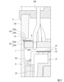
図1に示すように、回転電機1は、ステータ2と、ロータ3と、ケース4と、エンドカバー5と、温度センサ6(図3参照)と、回路基板7と、第一絶縁シート8と、第二絶縁シート9と、樹脂シート10と、を備える。本実施形態では、ケース4にステータ2が設けられることで、ステータユニットとして構成される。また、ステータユニットに温度センサ6と回路基板7とが設けられることで、ステータユニット組立体として構成される。
[First embodiment]
<Rotating Electric Machine>
As shown in Fig. 1, the rotating
図1において符号12は、シャフト11を回転可能に支持する軸受を示す。軸受12は、ケース4及びエンドカバー5のそれぞれに設けられている。回転電機1のシャフト11は、ケース4及びエンドカバー5にそれぞれ軸受12を介して回転可能に支持されている。以下、シャフト11の軸線CLに沿う方向を「軸方向」、軸線CLに直交する方向を「径方向」、軸線CL周りの方向を「周方向」とする。
In FIG. 1, the
<ステータ>
ステータ2は、円筒状(筒状)を有する。ステータ2は、ステータコア20と、インシュレータ21,22と、コイル23と、を備える。
<Stator>
The
例えば、ステータコア20は、鉄製の薄板材(電磁鋼板)を軸方向に複数枚積層することにより形成されている。ステータコア20は、軸線CLと同軸の環状を有する。ステータコア20は、ケース4の内周面に固定されている。
For example, the
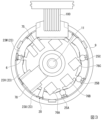
図9に示すように、ステータコア20は、円環状のコア本体20aと、コア本体20aの内周面から径方向中心(ステータ2の中心)に向けて所定の長さで突出すると共にコア本体20aの内周面に沿って軸方向に所定の長さで形成される複数(例えば本実施形態では9つ)の突出部20bと、を備える。
突出部20bは、径方向の内側端部である突出端部20cから更に周方向に延びる突出フランジ部20dを備える。本実施形態では、突出フランジ部20dは、突出端部20cを境に周方向両側に略同じ長さで延びている。9つの突出部20bは、それぞれ周方向に略同じ間隔をあけて配置されている。本実施形態では、9つの突出部20bは、それぞれ周方向に略40度(中心角)の間隔で配置されている。
各突出部20bに設けられる突出フランジ部20dは、それぞれ周方向に間隔をあけて配置されている。ステータコア20は、それぞれの突出部20bの突出端部20cで囲まれる空間91を有する。
As shown in Figure 9, the
The protruding
The protruding
<インシュレータ>
図1に示すように、インシュレータ21,22は、ステータコア20に装着されている。インシュレータ21,22は、軸方向に分割可能とされている(図5参照)。インシュレータ21,22は、コア本体20a(図9参照)の内周部に装着されている。インシュレータ21,22は、ステータコア20の軸方向の両側に装着されている。インシュレータ21,22は、ステータコア20の軸方向の一方側に装着された第一インシュレータ21と、ステータコア20の軸方向の他方側に装着された第二インシュレータ22と、により構成される。本実施形態では、第一インシュレータ21と第二インシュレータ22とを組み合わせることにより、インシュレータ21,22が形成される。
<Insulator>
As shown in Fig. 1, the
コイル23は、複数の突出部20b(図9参照)のそれぞれにインシュレータ21,22を介して巻線24を巻回してなる。図3に示すように、コイル23は、複数の異なる相(例えば、U相、V相、W相)のコイル23U,23V,23Wを一組とし、三組からなる。U相、V相、W相のコイル23U,23V,23Wは、ステータコア20の周方向に沿ってこの順に配列されている。周方向に隣り合うコイル23同士は、間隔をあけて配置されている。本実施形態では、9つのコイル23は、それぞれ周方向に略40度(中心角)の間隔で配置されている。すなわち、三組のコイル23U,23V,23Wは、それぞれ周方向に略120度(中心角)の間隔で配置されている。図4に示すように、コイル23は、軸方向両端側で巻線24が屈曲した屈曲部24aをそれぞれ有する。屈曲部24aは、周方向に隣り合うコイル23の巻線24の軸方向両側にそれぞれ設けられている。屈曲部24aは、U相、V相、W相のコイル23U,23V,23Wの巻線24の軸方向両側にそれぞれ設けられている。
The
<ロータ>
図1に示すように、ロータ3は、ステータ2の空間91(内部空間)に配置されている。ロータ3は、ステータ2の径方向内側にステータ2と間隔をあけて配置されている。ロータ3は、シャフト11に固定されている。ロータ3は、軸線CL周りにシャフト11と一体で回転可能である。ロータ3は、マグネットヨーク30と、マグネット31と、を備える。
<Rotor>
As shown in Fig. 1, the
例えば、マグネットヨーク30は、アルミニウム等の金属材により形成されている。マグネットヨーク30は、軸線CLと同軸の環状を有する。例えば、マグネットヨーク30の内周面は、接着剤によりシャフト11の外周面に固定されている。
例えば、マグネット31は、永久磁石である。マグネット31は、軸線CLと同軸の環状を有する。マグネット31は、マグネット31に設けられた挿入孔にマグネットヨーク30を挿入することでマグネットヨーク30に固定されている。これにより、マグネット31は、マグネットヨーク30及びシャフト11と一体に回転できる。なお、マグネット31は、ステータ2の内周面に対向する部位にN-S極の複数の磁極を有する。N-S極の複数の磁極は、周方向に交互に設けられている。
For example, the
For example, the
<ケース>
ケース4は、ステータ2を収容する有底円筒状(有底筒状)を有する。ケース4(有底筒状ケース)は、ケース4の軸方向の一方側に開口端41を有する。ケース4は、ケース4の軸方向の他方側に底部42を有する。例えば、ケース4は、アルミニウム等の金属製である。
<Case>
The
ケース4は、軸方向に延びる円筒状の円筒部40(以下「ケース筒部40」ともいう。)と、ケース筒部40の軸方向の他方側に連結される底部42と、を備える。ケース筒部40及び底部42は、同一の部材で一体に形成されている。例えば、ケース4の底部42は、アルミニウム等の金属製板材で形成された取付部材101(図1参照)に取り付けられる。ケース4の他方面は、取付部材101への取付面となる。
ケース4の底部42は、中央部に一方の面と他方の面とに連通する連通孔を有する。ケース4の底部42は、軸受12が装着される軸受装着部を有する。軸受装着部に装着される軸受12の孔と連通孔とは、互いに連通している。
The
The bottom 42 of the
図2に示すように、ケース4は、ケース筒部40の軸方向の一方側に段部43を有する。段部43は、軸方向から見て円環状の環状面43a(以下「ケース側環状面43a」ともいう。)と、ケース側環状面43aの外周縁から軸方向の一方側に延びる周面43b(以下「ケース側周面43b」ともいう。)と、を有する。
ケース側周面43bの軸方向の長さは、ケース側環状面43aの径方向の長さよりも大きい。
2, the
The axial length of the case side
<エンドカバー>
図1に示すように、エンドカバー5は、ケース4の軸方向の一方側の開口端41に取り付けられている。例えば、エンドカバー5は、アルミニウム等の金属製である。エンドカバー5は、軸方向に延びる円筒状の円筒部50(以下「カバー筒部50」ともいう。)と、カバー筒部50の軸方向の一方側に連結される蓋部51と、を備える。カバー筒部50の軸方向の長さは、ケース筒部40の軸方向の長さよりも小さい。カバー筒部50及び蓋部51は、同一の部材で一体に形成されている。エンドカバー5の蓋部51は、ケース4側の中央部に軸受12が装着される軸受装着部を有する。
<End cover>
As shown in FIG. 1, the
図2に示すように、エンドカバー5は、カバー筒部50の軸方向の他方側から軸方向の他方側に起立する凸部52を有する。凸部52は、軸方向から見て円環状の環状面52a(以下「カバー側環状面52a」ともいう。)と、カバー側環状面52aの外周縁から軸方向の一方側に延びる周面52b(以下「カバー側周面52b」ともいう。)と、を有する。
カバー側環状面52aの径方向の長さは、ケース側環状面43aの径方向の長さよりも大きい。
カバー側周面52bの軸方向の長さは、ケース側周面43bの軸方向の長さよりも小さい。
カバー側周面52bの軸方向の長さは、カバー側環状面52aの径方向の長さよりも大きい。
2, the
The radial length of the cover side
The axial length of the cover side
The axial length of the cover side
エンドカバー5は、カバー筒部50の凸部52がケース筒部40の段部43に嵌め合わされることにより、ケース4の一方側の開口端41に取り付けられている。カバー側周面52bは、ケース側周面43bに当接している。カバー側環状面52aは、ケース側環状面43aに対し軸方向に離れている。
The
<温度センサ>
例えば、温度センサ6は、PTC(Positive Temperature Coefficient)サーミスタである。温度センサ6は、ステータ2のエンドカバー5の側に設けられている。
温度センサ6は、温度が一定以上になると抵抗値が急激に増加する機能を有する。温度センサ6は、不図示のモータ駆動用電源及び回路基板7のそれぞれに電気的に接続されている。例えば、温度センサ6は、温度センサ6付近の温度が所定値以上となった場合に、回路基板7への電力供給を停止するよう抵抗値が増加する。
<Temperature sensor>
For example, the
The
図4に示すように、温度センサ6は、隣り合うコイル23における巻線24の屈曲部24aの間に配置されている。温度センサ6は、巻線24の屈曲部24aに当接している。温度センサ6は、周方向に隣り合う2つのコイル23(本実施形態では隣り合うコイル23V,23W)のそれぞれの巻線24の屈曲部24aに当接している。本実施形態では、温度センサ6は1つのみ設けられている。本実施形態では、温度センサ6は、周方向に隣り合うV相コイル23VとW相コイル23Wとにおける巻線24の屈曲部24aの間に配置されている。
As shown in FIG. 4, the
例えば、不図示の治具により温度センサ6を隣り合う巻線24の屈曲部24aのそれぞれに当接させる。この状態で、不図示の充填装置により、巻線24の屈曲部24aと温度センサ6との当接部の周囲に樹脂を充填する。これにより、温度センサ6が巻線24の屈曲部24aに当接した状態を保持することができる。
For example, the
<回路基板>
回路基板7は、回転電機1の駆動を制御する。図1に示すように、回路基板7は、ケース4の軸方向外端より内側となるケース4内部に配置されている。回路基板7は、第一インシュレータ21の上面から上方に突出して設けられる後述の当接部82により支持されている。回路基板7は、当接部82の支持により、第一インシュレータ21の上面から所定の間隔をあけて配置されている。回路基板7は、ステータ2とエンドカバー5との間に配置されている。回路基板7は、ケース4の一方側の開口端41よりも軸方向内側に配置されている。回路基板7は、ケース側環状面43aよりも僅かに軸方向内側に配置されている(図2参照)。回路基板7は、ケース4の内周面に固定されている。
<Circuit board>
The
図7Aに示すように、回路基板7は、平面視で円環状の基板本体70と、コイル23(図1参照)に供給される電流を検出するための抵抗器75と、スイッチング素子としての電界効果トランジスタ76A~76C(FET:Field Effect Transistor」)と、シャフト11(図1参照)の回転角度を検出するためのエンコーダ78と、各種の電子部品79と、モータコントローラ用IC102と、を備える。
As shown in FIG. 7A, the
モータコントローラ用IC102は、各FET76A~76Cを所定の順序で選択的にオン・オフさせることによりU相、V相、W相のコイル23U,23V,23Wの各相に電流を発生させる。
図7Bは、回路基板7において図7Aの反対側の面(裏面)を平面視した図である。
図7Bに示すように、回路基板7は、マグネット31の磁気の状態(磁場の大きさ・方向)を検出するための磁気センサ77A~77Cを備える。
The
FIG. 7B is a plan view of the surface (rear surface) of the
As shown in FIG. 7B, the
基板本体70は、軸線CLと同軸の軸孔71と、第一インシュレータ21と係合する係合部72A~72C(基板側係合部)と、ケーブル100(図1参照)を電気的に接続するための接続孔73と、コイル23の引き出し線25A~25C(図3参照)を通すための切欠き74A~74Cと、を有する。
The
平面視で、軸孔71は、円形状を有する。軸孔71の直径は、シャフト11の外径よりも大きい。回路基板7は、シャフト11の径方向外側にシャフト11と間隔をあけて配置されている(図1参照)。
In plan view, the
平面視で、係合部72A~72Cは、周方向に延びる長孔形状を有する。係合部72A~72Cは、周方向に間隔をあけて複数(例えば本実施形態では3つ)設けられている。3つの係合部72A~72C(第一係合部72A、第二係合部72B及び第三係合部72C)は、それぞれ周方向に略同じ間隔をあけて配置されている。
In a plan view, the
平面視で、接続孔73は、円形状を有する。接続孔73は、周方向に間隔をあけて複数(例えば本実施形態では8つ)設けられている。8つの接続孔73は、周方向において第一係合部72Aと第三係合部72Cとの間に配置されている。
In plan view, the
平面視で、切欠き74A~74Cは、回路基板7の径方向外方に開口する凹形状を有する。切欠き74A~74Cは、周方向に間隔をあけて複数(例えば本実施形態では3つ)設けられている。3つの切欠き74A~74C(第一切欠き74A、第二切欠き74B及び第三切欠き74C)は、周方向において第二係合部72Bと第三係合部72Cとの間に配置されている。
In a plan view, the
例えば、抵抗器75は、シャント抵抗器である。本実施形態では、抵抗器75は、1つのみ設けられている。抵抗器75は、基板本体70(回路基板7)のエンドカバー5の側の面に設けられている。すなわち、抵抗器75は、基板本体70のステータ2側の面とは反対側の面に設けられている。
For example, the
FET76A~76Cは、周方向に間隔をあけて複数(例えば本実施形態では3つ)設けられている。FET76A~76Cは、基板本体70のエンドカバー5の側の面に設けられている。すなわち、FET76A~76Cは、基板本体70において抵抗器75と同じ側の面に設けられている。
The
3つのFET76A~76C(第一FET76A、第二FET76B及び第三FET76C)は、それぞれ3つの切欠き74A~74C(第一切欠き74A、第二切欠き74B及び第三切欠き74C)の近傍に配置されている。3つのFET76A~76Cと3つの切欠き74A~74Cとの間には、それぞれコイル23の引き出し線25A~25C(図3参照)を半田付けするための領域26A~26Cが設けられている。
The three
領域26A~26Cは、コイル23の引き出し線25A~25Cの近傍に配置されている。これにより、コイル23の引き出し線25A~25Cが過度に長くなることを抑制し、ノイズの発生を抑えることができる。
FET76A~76Cは、コイル23の引き出し線25A~25Cと電気的に接続されている。例えば、コイル23の引き出し線25A~25Cは、領域26A~26Cで半田付けされた後、回路基板7上に形成された配線によって、FET76A~76Cに電気的に接続される。FET76A~76Cは、領域26A~26Cの近傍に配置されていることにより、回路基板7上の配線の短縮化、単純化を図ることができる。
The
The
例えば、磁気センサ77A~77Cは、ホール素子である。磁気センサ77A~77Cは、周方向に間隔をあけて複数(例えば本実施形態では3つ)設けられている。磁気センサ77A~77Cは、基板本体70のステータ2側の面(図7Bの面)に設けられている。
For example, the
図7Bの平面視で、3つの磁気センサ77A~77C(第一磁気センサ77A、第二磁気センサ77B及び第三磁気センサ77C)は、それぞれマグネット31の回転による磁束の変化を、静止側の基板本体70の特定位置に置かれた磁気センサで検出する。
例えば、磁気センサは、平面視で見たときのマグネット31の直上であって、軸方向においてマグネット31に近接して配置されているとよい。これにより、マグネット31の回転検出感度を向上することができる。
In the plan view of Figure 7B, three
For example, the magnetic sensor may be disposed directly above the
例えば、エンコーダ78は、発光素子に赤外線発光ダイオード(IR LED)を使用した光学式エンコーダである。例えば、エンコーダ78は、シャフト11に取り付けられた不図示の検出体用円板(スリット孔を有する円板)の回転を検出し、光のオン/オフ信号を発生させる。本実施形態では、エンコーダ78は、1つのみ設けられている。エンコーダ78は、回路基板7に設けられる電子部品の中で最も大きい設置面積を有する。エンコーダ78は、基板本体70のエンドカバー5の側に設けられている。
For example, the
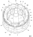
図8に示すように、平面視で、エンコーダ78は、3つのFET76A~76Cのうち最も左側に位置する第一FET76Aと抵抗器75との間に配置されている。すなわち、エンコーダ78は、周方向において第一FET76Aと抵抗器75との間に配置されている。本実施形態では、平面視で、抵抗器75は、軸孔71を挟んで第二FET76Bとは反対側に配置されている。なお、図8においては、基板本体70の軸孔71以外の孔、切欠き等の図示を省略している。
As shown in FIG. 8, in plan view, the
<第一絶縁シート>
図1に示すように、第一絶縁シート8は、ステータ2及びロータ3と回路基板7との間に配置されている。第一絶縁シート8は、少なくとも回路基板7とコイル23とを絶縁する。第一絶縁シート8は、軸方向から見て、円環状を有する。第一絶縁シート8は、中央部にシャフト11が挿通される挿通孔を形成する内周縁部を有する。第一絶縁シート8の内周縁部は、シャフト11の径方向外側にシャフト11と間隔をあけて配置されている。これにより、第一絶縁シート8は、シャフト11の回転を許容する。第一絶縁シート8は、第一インシュレータ21により支持されている。具体的には、第一絶縁シート8は、第一インシュレータ21に複数設けられる後述の当接部81に支持されている。
<First insulation sheet>
As shown in FIG. 1, the first insulating
<第二絶縁シート>
第二絶縁シート9は、回路基板7とエンドカバー5との間に配置されている。第二絶縁シート9は、回路基板7と隣り合う位置に配置されている。第二絶縁シート9は、少なくとも回路基板7とエンドカバー5とを絶縁する。第二絶縁シート9は、軸方向から見て、第一絶縁シート8よりも大きい円環状を有する。第二絶縁シート9は、中央部にシャフト11が挿通される挿通孔を形成する内周縁部を有する。第二絶縁シート9の内周縁部は、シャフト11の径方向外側にシャフト11と間隔をあけて配置されている。これにより、第二絶縁シート9は、シャフト11の回転を許容する。
<Second insulating sheet>
The second
図2に示すように、第二絶縁シート9は、内周縁から外周縁に向けて径方向全体にわたって延びている。第二絶縁シート9の外周縁部は、ケース側周面43bの近傍に配置されている。第二絶縁シート9の外周縁部は、ケース4の一方側の開口部分とエンドカバー5の円筒部50の先端とに挟まれている。第二絶縁シート9は、ケース筒部40の段部43とカバー筒部50の凸部52とに挟まれることにより、保持されている。第二絶縁シート9は、ケース側環状面43aとカバー側環状面52aとに当接する。第二絶縁シート9は、ケース側周面43bから僅かに離れている。第二絶縁シート9は、軸方向において回路基板7のエンドカバー5の側の面から僅かに離れている。回路基板7のエンドカバー5の側の面と第二絶縁シート9との間に空隙を設けることにより、回路基板7とエンドカバー5との更なる絶縁性を確保している。
As shown in FIG. 2, the second insulating
<第一絶縁シート及び第二絶縁シートの特性>
第一絶縁シート8及び第二絶縁シート9のそれぞれは、絶縁性及び難燃性を兼ね備えるシートである。第一絶縁シート8及び第二絶縁シート9のそれぞれは、アラミド繊維により形成されている。例えば、第一絶縁シート8及び第二絶縁シート9のそれぞれは、絶縁紙である。第一絶縁シート8及び第二絶縁シート9のそれぞれは、0.25mm以上の厚みを有する。例えば、第一絶縁シート8及び第二絶縁シート9のそれぞれは、0.25mm以上0.35mm以下の厚みを有する。
<Characteristics of the first insulating sheet and the second insulating sheet>
Each of the first insulating
例えば、第一絶縁シート8及び第二絶縁シート9のそれぞれは、ASTM E1530に準拠した測定方法での測定温度150℃における熱伝導率が0.12W/m・K以上0.14W/m・K以下である。
For example, the first insulating
第一絶縁シート8及び第二絶縁シート9のそれぞれは、220℃環境下におけるLOI(Limiting Oxygen index)値が20.8%より高い。ここで、LOI値は、難燃性を測る尺度として用いられる数値であり、「JIS K7201限界酸素指数」で規定されている。例えば、第一絶縁シート8及び第二絶縁シート9のそれぞれは、厚みが0.25mmの場合、220℃環境下におけるLOI値が22%以上25%以下である。
Each of the first insulating
<樹脂シート>
図1に示すように、樹脂シート10は、ケース4の底部42とステータ2との間に配置されている。樹脂シート10は、ケース4の底部42と第二インシュレータ22との間に配置されている。樹脂シート10は、軸方向から見て、円環状を有する。樹脂シート10は、中央部にシャフト11が挿通される挿通孔を形成する内周縁部を有する。樹脂シート10の内周縁部は、シャフト11の径方向外側にシャフト11と間隔をあけて配置されている。これにより、樹脂シート10は、シャフト11の回転を許容する。
<Resin sheet>
As shown in Fig. 1, the
本実施形態では、樹脂シート10の位置ずれを抑制するために、ケース4の底部42に、樹脂シート10の挿通孔の内周縁と当接する円環状の環状凸部44が設けられている。環状凸部44の軸方向の高さは、樹脂シート10の厚さよりも僅かに大きい。例えば、樹脂シート10の挿通孔の内径は、環状凸部44の外径に合わせて設計されている。
なお、樹脂シート10の位置ずれを抑制するための構成は、環状凸部44を設けることに限らない。例えば、環状凸部44を設ける代わりに、樹脂シート10の外径をケース4の内径に合わせてもよい。
本実施形態では、第二インシュレータ22は、環状凸部44に当接することにより軸方向の位置が決まる。よって、軸方向において、樹脂シート10は、第二インシュレータ22から離れている。しかし、これに限らず、樹脂シート10は、第二インシュレータ22に当接していてもよい。
In this embodiment, in order to suppress misalignment of the
The configuration for suppressing misalignment of the
In the present embodiment, the axial position of the
樹脂シート10は、シリコーンにより形成されている。樹脂シート10は、0.2mm以上の厚みを有する。例えば、樹脂シート10は、0.2mm以上0.3mm以下の厚みを有する。
例えば、樹脂シート10は、ASTM D5470に準拠した測定方法での荷重20psiにおける熱伝導率が1.0W/m・K以上1.4W/m・K以下である。
樹脂シート10は、材料の燃えにくさの度合いを表す規格であるUL94規格においてV-0を有する。
The
For example, the
The
<第一インシュレータ>
図1に示すように、第一インシュレータ21は、ステータコア20と同軸の環状の環状部80と、第一絶縁シート8のステータ2の側の面に当接する当接部81(以下「シート側当接部81」ともいう。)と、回路基板7のステータ2の側の面に当接する当接部82(以下「基板側当接部82」ともいう。)と、回路基板7のステータ2の側の面に向けて延びる複数の延在部83(図6参照)と、回路基板7の複数の係合部72A~72Cのそれぞれを通じて回路基板7に係合する係合部84A~84C(図5参照)と、を備える。
<First Insulator>
As shown in FIG. 1, the
シート側当接部81は、環状部80の内周側から軸方向の一方側に向けて延びている。シート側当接部81の先端は、第一絶縁シート8のステータ2の側の面に当接している。シート側当接部81は、周方向に間隔をあけて複数(例えば本実施形態では9つ)設けられている(図6参照)。9つのシート側当接部81は、それぞれ周方向に略同じ間隔をあけて配置されている(図6参照)。
The seat
基板側当接部82は、環状部80の外周側から軸方向の一方側に向けて延びている。基板側当接部82の先端は、回路基板7のステータ2の側の面に当接している。基板側当接部82は、シート側当接部81及び延在部83のそれぞれよりも長く軸方向の一方側に向けて延びている(図6参照)。基板側当接部82は、周方向に間隔をあけて複数(例えば本実施形態では11個)設けられている(図6参照)。
The board-
図6に示すように、延在部83は、環状部80の外周側から軸方向の一方側に向けて延びている。延在部83は、周方向に間隔をあけて複数(例えば本実施形態では4つ)設けられている。延在部83の先端は、回路基板7のステータ2の側の面から離れている。すなわち、延在部83は、回路基板7に当接していない。延在部83の先端と回路基板7のステータ2の側の面との間には、隙間が形成される。延在部83の先端と回路基板7との間の隙間は、ケーブル100の配線部1001(図2参照)を回路基板7に電気的に接続する際に、配線部1001が収容される空間のための隙間である。この隙間は、下記の如く出っ張った配線部1001の逃げとして機能する。具体的には、配線部1001を接続孔73に挿通した状態で配線部1001を回路基板7に半田付けを行う。すると、配線部1001及び半田が回路基板7のステータ2の側の面からステータ2の側に出っ張る。この出っ張った配線部1001の逃げとして隙間を設けている。
As shown in FIG. 6, the
図6に示すように、係合部84A~84C(インシュレータ側係合部)は、環状部80の外周側から軸方向の一方側に向けて延びている。係合部84A~84Cは、基板側当接部82よりも長く軸方向の一方側に向けて延びている。係合部84A~84Cは、回路基板7に係合可能なフック形状を有する(図5参照)。係合部84A~84Cは、環状部80から軸方向の一方側に向けて延びた後に径方向外方へ向けて屈曲している。これにより、係合部84A~84Cは、は、回路基板7との係合状態を維持可能にする。
As shown in FIG. 6, the
係合部84A~84Cは、周方向に間隔をあけて複数(例えば本実施形態では3つ)設けられている。3つの係合部84A~84C(第一係合部84A、第二係合部84B及び第三係合部84C)は、それぞれ周方向に略同じ間隔をあけて配置されている。3つの係合部84A~84C(第一係合部84A、第二係合部84B及び第三係合部84C)は、それぞれ3つの係合部72A~72C(第一係合部72A、第二係合部72B及び第三係合部72C)を通じて回路基板7に係合する(図5参照)。
The engaging
11個の基板側当接部82は、周方向において第一係合部84Aと第二係合部84Bとの間に配置された5個の基板側当接部82と、周方向において第二係合部84Bと第三係合部84Cとの間に配置された5個の基板側当接部82と、周方向において第一係合部84Aと第三係合部84Cとの間に配置された1個の基板側当接部82と、である。
4個の延在部83は、周方向において第一係合部84Aと第三係合部84Cとの間に配置されている。
The eleven board
The four
<ケース内の樹脂の充填構造>
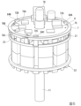
図10に示すように、ケース4とインシュレータ21,22(第一インシュレータ21及び第二インシュレータ22)との間の隙間は、樹脂90により充填されている。これにより、ケース4とインシュレータ21,22との間の隙間は、樹脂90で満たされている。ステータコア20における複数の突出部20b(図9参照)のそれぞれの間の隙間は、樹脂90により充填されている。これにより、ステータコア20における複数の突出部20bのそれぞれの間の隙間は、樹脂90で満たされている。ケース4、ステータ2及び温度センサ6(図4参照)は、樹脂90により一体化されている。
<Resin filling structure inside the case>
As shown in Fig. 10, the gaps between the
例えば、樹脂90をケース4内に充填する充填工程は、以下の手順で行う。
例えば、コイル23の屈曲部24aに温度センサ6を不図示の治具を用いて当接し、温度センサ6のリード線60を外に出す。その後、この状態で、ケース4内に樹脂90を充填する(図4参照)。これにより、ケース4、ステータ2及び温度センサ6は、樹脂90により一体化される。その後、リード線60を回路基板7のスリット(不図示)に通して回路基板7に半田付けする。このようにして、リード線60を回路基板7に接続する配線工程が行われる。
For example, the filling step of filling the
For example, the
樹脂90は、シャフト11及びロータ3が挿入される空間91を中心部分に残し、それ以外のケース4内の隙間に充填されている。例えば、樹脂90は、エポキシ樹脂等の熱硬化性樹脂である。樹脂90は、ケース4内の軸方向においてコイル23(図1参照)が露出しない位置まで充填されている。
The
例えば、樹脂90は、ASTM D5470に準拠した測定方法での荷重20psiにおける熱伝導率が0.1W/m・K以上0.9W/m・K以下である。樹脂90は、材料の燃えにくさの度合いを表す規格であるUL94規格においてV-0を有する。樹脂90は、ASTM D257に準拠した測定方法での25℃環境下における体積低効率が1×10¹⁵Ω・cmであり、100℃環境下における体積低効率が1×10¹⁵Ω・cmであり、150℃環境下における体積低効率が3×10¹³Ω・cmである。
For example, the
例えば、ケース4にステータ2を設置し、樹脂90をケース4内に充填させることにより製造するステータユニットの製造方法は、以下の手順(工程)により行う。
先ず、ケース4内に樹脂シート10を入れる(シート配置工程)。
次に、ケース4内にステータ2を入れる(ステータ配置工程)。
次に、ケース4内にロータ3と略同じ大きさの円筒状の型材を入れる(第一充填準備工程)。例えば、型材は、空間91を形成する複数の突出端部20cとロータ3の外周面とが当接する大きさの円筒状を有する。型材は、例えば、ポリテトラフルオロエチレン(PTFE:Polytetrafluoroethylene)のシートである。
次に、不図示の治具を用いて温度センサ6を隣り合うコイル23の屈曲部24aに当接した状態で隣り合うコイル23の屈曲部24aの間に配置する(第二充填準備工程)。
次に、ケース4の内周面と型材の外周面との間に樹脂90を不図示の充填装置を用いて充填する(樹脂充填工程)。
次に、樹脂90を充填したケース4を真空槽に入れてから充填させた樹脂90内に含まれる気泡を除去(脱気)するため真空引きし、脱気する(充填仕上げ工程)。
次に、型材を取り出す(充填完了工程)。これにより、樹脂90を充填したケース4内にロータ3が入る空間91が形成される。
For example, a method for manufacturing a stator unit by placing the
First, the
Next, the
Next, a cylindrical mold material having approximately the same size as the
Next, using a jig (not shown), the
Next,
Next, the
Next, the mold material is removed (filling completion step), whereby a
<作用効果>
以上説明したように、上記実施形態の回転電機1は、筒状のステータ2と、ステータ2の内部空間に配置されるロータ3と、ステータ2を収容する有底筒状のケース4と、ケース4の一方側の開口端41に取り付けられるエンドカバー5と、温度センサ6と、を備え、ステータ2は、ステータ2の中心に向けて突出する複数の突出部20bを有するステータコア20と、ステータコア20に装着されるインシュレータ21,22と、複数の突出部20bのそれぞれにインシュレータ21,22を介して巻線24を巻回してなるコイル23と、を備え、温度センサ6は、ステータ2のエンドカバー5の側において、隣り合うコイル23における巻線24の屈曲部24aの間に配置されている。
この構成によれば、温度センサ6は、ステータ2のエンドカバー5の側において、隣り合うコイル23における巻線24の屈曲部24aの間に配置されていることで、回転電機1において最も発熱し易い屈曲部24aの温度を検出することができる。例えば、温度センサ6の検出結果(回転電機1のコイル23における巻線24の屈曲部24aの温度)に基づいて、回転電機1の駆動を最適に動作させることができる。したがって、温度センサ6を用いることにより、回転電機1の発熱による不具合を抑制することができる。
<Action and effect>
As described above, the rotating
According to this configuration, the
上記実施形態では、温度センサ6は、巻線24の屈曲部24aに当接していることで、巻線24の屈曲部24aの温度を直に検出することができる。したがって、回転電機1において最も発熱し易い屈曲部24aの温度をより高い精度で検出することができる。
In the above embodiment, the
上記実施形態では、回転電機1の駆動を制御する回路基板7を更に備える。回路基板7は、ケース4内に配置され、かつ、ステータ2とエンドカバー5との間に配置されていることで、以下の効果を奏する。
回路基板7がケース4外(エンドカバー5内)に配置される場合と比較して、回路基板7の組付けが容易となる。したがって、回転電機1の組立を効率良く行うことができる。
In the above embodiment, the rotating electric machine further includes a
This makes it easier to assemble the
上記実施形態では、第一インシュレータ21は、回路基板7のステータ2の側の面に当接する基板側当接部82を有することで、以下の効果を奏する。
基板側当接部82により回路基板7をコイル23から離間させて軸方向の所定の位置で支持することができる。具体的には、基板側当接部82により回路基板7をコイル23から離間させて配置することで、発熱源であるコイル23から回路基板7を所定の間隔で離間することができる。また、ロータ3のマグネット31を3つの磁気センサ77A~77Cにより最適に検出可能な位置に設定することができる。
In the above embodiment, the
The
上記実施形態では、回路基板7は、周方向に所定の間隔をあけて配置される複数の係合部72A~72Cを有する。第一インシュレータ21は、複数の係合部72A~72Cのそれぞれに対応する係合部84A~84Cを有する。回路基板7の複数の係合部72A~72Cに第一インシュレータ21の係合部84A~84Cが挿通された状態で回路基板7と第一インシュレータ21とが係合することで、以下の効果を奏する。
複数の係合部84A~84Cにより回路基板7の周方向及び径方向の位置を規定しつつ回路基板7を保持することができる。
In the above embodiment, the
The plurality of engaging
上記実施形態では、ケース4とケース4内に配置されたステータ2のインシュレータ21,22との間及びステータコア20における複数の突出部20bのそれぞれの間の隙間が樹脂90により満たされ、ケース4、ステータ2及び温度センサ6が一体化されていることで、以下の効果を奏する。
ケース4内の隙間に充填した樹脂90によりステータ2のコイル23から発せられた熱の熱伝導性が向上され、発せられた熱がケース4全体から放たれることで、回転電機1の昇温(コイル23の昇温)を抑制することができる。加えて、ステータ2のコイル23に対する温度センサ6の接触状態が維持されることで良好となり、温度の検出精度が向上する。したがって、温度センサ6を用いることにより、回転電機1(コイル23)の発熱による不具合をより効果的に抑制することができる。
In the above embodiment, the gaps between the
The
上記実施形態では、ケース4は、他方側に底部42を有する有底筒状の有底筒状ケースであり、底部42とステータ2との間に配置される樹脂シート10を更に備えることで、以下の効果を奏する。
ケース4の底部42とステータ2との間に樹脂よりも更に熱伝導率の高い樹脂シート10を配置することにより、ケース4の底部42が取付部材101に取り付けられる場合、コイル23から発生する熱の取付部材101への熱伝導(放熱)を促進し、回転電機1(コイル23)の昇温を抑制することができる。また、ケース4の底部42とケース4内に配置されるステータ2との間の絶縁性を、樹脂シート10により確保することが可能となる。
In the above embodiment, the
By disposing the
上記実施形態では、回路基板7は、コイル23に供給される電流を検出するための抵抗器75を有し、抵抗器75は、回路基板7のエンドカバー5の側の面に配置されていることで、以下の効果を奏する。
発熱源であるコイル23と抵抗器75との間に回路基板7が介在することで、抵抗器75をコイル23から離し、抵抗器75が熱の影響を受けることを抑制することができる。したがって、コイル23に供給される電流の検出精度の低下を抑制することができる。
In the above embodiment, the
By interposing the
上記実施形態では、回路基板7は、複数のFET76A~76Cと、エンコーダ78と、を更に有し、平面視で、エンコーダ78は、複数のFET76A~76Cのうち最も左側に位置する第一FET76Aと抵抗器75との間に配置されていることで、以下の効果を奏する。
回路基板7のエンドカバー5の側の面は、複数の電子部品が取り付けられるため、各電子部品の配置スペースは限られるものの、抵抗器75、エンコーダ78及び複数のFET76A~76Cを限られた回路基板7のスペースに好適に配置することができる。
In the above embodiment, the
Since multiple electronic components are attached to the surface of the
上記実施形態では、回転電機1は、回路基板7とコイル23とを絶縁する第一絶縁シート8が回路基板7とステータ2との間に配置され、回路基板7とエンドカバー5とを絶縁する第二絶縁シート9が回路基板7とエンドカバー5との間に配置されることで、以下の効果を奏する。
第一絶縁シート8により回路基板7とコイル23とを絶縁すると共に遮断し、第二絶縁シート9により回路基板7とエンドカバー5とを絶縁することで、回路基板7及びコイル23並びに回路基板7及びエンドカバー5を近接して配置した場合においても、絶縁性の確保が可能となり、安全性を向上することができる。加えて、軸方向の絶縁として第一絶縁シート8及び第二絶縁シート9のそれぞれを採用することにより、封止樹脂(モールド樹脂)を絶縁材として用いた場合と比較して軸方向の厚みが小さくて済むため、軸方向において回転電機1を小型化することができる。
加えて、ケース4とケース4内に配置されるステータ2との隙間に樹脂90が充填され、ステータ2のコイル23が樹脂90で覆われることにより絶縁性が確保されると共に、第一絶縁シート8により更なる絶縁性の確保が可能となる。加えて、第二絶縁シート9により回路基板7とエンドカバー5とが絶縁されることで、金属製のエンドカバー5を使用可能となり、電磁両立性(EMC:Electromagnetic Compatibility)を実現し、かつ、放熱効果を高めることができる。
In the above embodiment, the
By insulating and blocking the
In addition, the gap between the
上記実施形態では、第一絶縁シート8及び第二絶縁シート9のそれぞれは、220℃環境下におけるLOI値が20.8%より高いことで、以下の効果を奏する。
220℃環境下におけるLOI値が20.8%より高い材料は、耐熱性、難燃性を有し、例えばコイル23の周辺温度が200℃まで上がったとしても電気的特性、機械的特性に対してほとんど影響がない。これにより、高温使用下においても、回路基板7及びコイル23並びに回路基板7及びエンドカバー5の絶縁性の確保が可能となり、安全性を更に向上することができる。
In the above embodiment, each of the first insulating
A material with an LOI value of more than 20.8% in an environment of 220° C. has heat resistance and flame retardancy, and has almost no effect on electrical and mechanical properties even if the temperature around the
上記実施形態では、第一インシュレータ21は、第一絶縁シート8のステータ2の側の面に当接するシート側当接部81を有することで、以下の効果を奏する。
シート側当接部81により第一絶縁シート8を軸方向において支持することができる。
In the above embodiment, the
The first insulating
上記実施形態では、第二絶縁シート9は、ケース4の一方側の開口部分とエンドカバー5の円筒部50の先端とに挟まれていることで、以下の効果を奏する。
ケース4の一方側の開口部分とエンドカバー5の円筒部50の先端とにより第二絶縁シート9を保持し、第二絶縁シート9を軸方向の所定の位置で位置決めすることができる。
In the above embodiment, the second insulating
The second
上記実施形態では、第一絶縁シート8及び第二絶縁シート9のそれぞれは、アラミド繊維により形成され、0.25mm以上の厚みを有することで、以下の効果を奏する。
第一絶縁シート8及び第二絶縁シート9のそれぞれにおいて、優れた耐電圧特性(例えば、UL規格において耐電圧5000V)を得ることができる。
In the above embodiment, each of the first insulating
Each of the first insulating
上記実施形態では、回路基板7は、磁気センサ77A~77Cを備え、磁気センサ77A~77Cは、回路基板7のステータ2の側の面に設けられていることで、以下の効果を奏する。
磁気センサ77A~77Cが回路基板7のエンドカバー5の側に設けられる場合と比較して、磁気センサ77A~77Cをロータ3に近づけることができるため、磁気センサ77A~77Cの検出精度を向上することができる。加えて、回路基板7とステータ2との間に第一絶縁シート8が設けられている場合、第一絶縁シート8によりコイル23と磁気センサ77A~77Cとの間の絶縁を行うことができる。
In the above embodiment, the
Compared to the case where the
[第二実施形態]
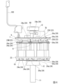
上述した第一実施形態では、ケース4が他方側に底部42を有する有底筒状の有底筒状ケースである例を挙げて説明したが、これに限らない。例えば、図11に示すように、ケース204は、筒状の筒状ケースであってもよい。図11において、上記第一実施形態と同一の構成には同一の符号を付し、その詳細説明は省略する。
[Second embodiment]
In the above-described first embodiment, an example has been described in which the
図11に示すように、回転電機201は、筒状ケース204と、筒状ケース204の他方側の開口端245に取り付けられるフロントカバー215と、フロントカバー215とステータ2との間に配置される樹脂シート10と、を備える。
As shown in FIG. 11, the rotating
筒状ケース204は、上記第一実施形態の有底筒状ケース4(図1参照)よりも軸方向の長さが大きい。図12に示すように、筒状ケース204は、軸方向の他方側の部位に第二段部246を有する。第二段部246は、軸方向から見て円環状の環状面246a(以下「第二ケース側環状面246a」ともいう。)と、第二ケース側環状面246aの外周縁から軸方向の他方側に延びる周面246b(以下「第二ケース側周面246b」ともいう。)と、を有する。第二ケース側周面246bの軸方向の長さは、第二ケース側環状面246aの径方向の長さよりも大きい。
The
例えば、フロントカバー215の他方側の部分は、アルミニウム等の金属製板材で形成された取付部材101に取り付けられる。フロントカバー215の他方面は、取付部材101への取付面となる。
For example, the other side of the
フロントカバー215は、筒状ケース204の軸方向の他方側の開口端245に取り付けられている。例えば、フロントカバー215は、アルミニウム等の金属製である。フロントカバー215は、軸方向の一方側の部分に、軸方向から見て円環状の環状面215a(以下「フロントカバー側環状面215a」ともいう。)と、フロントカバー側環状面215aの外周縁から軸方向の他方側に延びる周面215b(以下「フロントカバー側周面215b」ともいう。)と、を有する。
The
フロントカバー側環状面215aの径方向の長さは、第二ケース側環状面246aの径方向の長さよりも大きい。
フロントカバー側周面215bの軸方向の長さは、第二ケース側周面246bの軸方向の長さよりも小さい。
フロントカバー側周面215bの軸方向の長さは、フロントカバー側環状面215aの径方向の長さよりも小さい。
The radial length of the front cover side
The axial length of the front cover side
The axial length of the front cover side
フロントカバー215は、フロントカバー215の軸方向の一方側の外周部分が筒状ケース204の第二段部246に嵌め合わされることにより、筒状ケース204の他方側の開口端245に取り付けられている。フロントカバー側周面215bは、第二ケース側周面246bに当接している。フロントカバー側環状面215aは、第二ケース側環状面246aに対し軸方向に離れている。
The
樹脂シート10は、フロントカバー215とステータ2との間に配置されている。樹脂シート10は、フロントカバー215と第二インシュレータ22との間に配置されている。第二実施形態では、樹脂シート10の位置ずれを抑制するために、フロントカバー215の底部216に、樹脂シート10の挿通孔の内周縁と当接する円環状の環状凸部217が設けられている。環状凸部217の軸方向の高さは、樹脂シート10の厚さよりも僅かに大きい。例えば、樹脂シート10の挿通孔の内径は、環状凸部217の外径に合わせて設計されている。
なお、樹脂シート10の位置ずれを抑制するための構成は、環状凸部217を設けることに限らない。例えば、環状凸部217を設ける代わりに、樹脂シート10の外径を筒状ケース204の内径に合わせてもよい。
第二実施形態では、第二インシュレータ22は、環状凸部217に当接することにより軸方向の位置が決まる。よって、軸方向において、樹脂シート10は、第二インシュレータ22から離れている。しかし、これに限らず、樹脂シート10は、第二インシュレータ22に当接していてもよい。
The
The configuration for suppressing misalignment of the
In the second embodiment, the axial position of the
第二実施形態では、ケース204は、筒状の筒状ケースであり、筒状ケース204の他方側の開口端245に取り付けられるフロントカバー215と、フロントカバー215とステータ2との間に配置される樹脂シート10と、を備えることで、以下の効果を奏する。
フロントカバー215とステータ2との間に樹脂よりも更に熱伝導率の高い樹脂シート10を配置することにより、フロントカバー215が取付部材101に取り付けられる場合、コイル23から発生する熱の取付部材101への熱伝導(放熱)を促進し、回転電機201(コイル23)の昇温を抑制することができる。また、フロントカバー215とケース204内に配置されるステータ2との間の絶縁性を、樹脂シート10により確保することが可能となる。
In the second embodiment, the
By disposing the
<変形例>
なお、本発明の技術範囲は上述した実施形態に限定されるものではなく、本発明の趣旨を逸脱しない範囲において種々の変更を加えることが可能である。
<Modification>
The technical scope of the present invention is not limited to the above-described embodiment, and various modifications can be made without departing from the spirit of the present invention.
例えば、上述した第一実施形態では、平面視で、エンコーダ78は、複数のFET76A~76Cのうち最も左側に位置する第一FET76Aと抵抗器75との間に配置されている例を挙げて説明したが、これに限らない。
例えば、図13に示すように、回路基板7Aの平面視で、抵抗器75は、複数のFET76A~76Cのうち最も左側に位置する第一FET76Aとエンコーダ78との間に配置されていてもよい。すなわち、抵抗器75は、周方向において第一FET76Aとエンコーダ78との間に配置されている。本変形例では、平面視で、抵抗器75は、軸孔71を挟んで第三FET76Cとは反対側に配置されている。本変形例では、平面視で、エンコーダ78は、軸孔71を挟んで第二FET76Bとは反対側に配置されている。
For example, in the first embodiment described above, an example was given in which the
13, for example, in a plan view of the
本変形例では、平面視で、抵抗器75は、複数のFET76A~76Cのうち最も左側に位置する第一FET76Aとエンコーダ78との間に配置されていることで、以下の効果を奏する。
回路基板7Aのエンドカバー5の側の面は、複数の電子部品が取り付けられるため、各電子部品の配置スペースは限られるものの、抵抗器75、エンコーダ78及び複数のFET76A~76Cを限られた回路基板7Aのスペースに好適に配置することができる。
In this modified example, the
Since multiple electronic components are attached to the surface of the
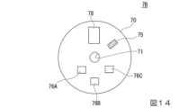
上述した第一実施形態では、平面視で、抵抗器75は、軸孔71を挟んで第二FET76Bとは反対側に配置されている例を挙げて説明したが、これに限らない。
例えば、図14に示すように、回路基板7Bの平面視で、抵抗器75は、軸孔71を挟んで第一FET76Aとは反対側に配置されていてもよい。本変形例では、平面視で、エンコーダ78は、軸孔71を挟んで第二FET76Bとは反対側に配置されている。
In the above-described first embodiment, an example has been described in which the
14 , in plan view of the
図13の例では、平面視で、抵抗器75は、軸孔71を挟んで第三FET76Cとは反対側に配置されている例を挙げて説明したが、これに限らない。
例えば、図15に示すように、回路基板7Cの平面視で、抵抗器75は、軸孔71を挟んで第二FET76Bとは反対側に配置されていてもよい。本変形例では、平面視で、エンコーダ78は、第三FET76Cの近傍に配置されている。
In the example of FIG. 13, the
15 , in plan view of the
上記実施形態では、温度センサ6は、巻線24の屈曲部24aに当接している例を挙げて説明したが、これに限らない。例えば、温度センサ6は、巻線24の屈曲部24aから離れていてもよい。例えば、温度センサ6は、樹脂90を介して巻線24の屈曲部24aの近傍に配置されていてもよい。これにより、樹脂90を介して巻線24の屈曲部24aの温度を検出することができる。
In the above embodiment, the
上記実施形態では、回転電機1(201)の駆動を制御する回路基板7を備え、回路基板7は、ケース4(204)の軸方向外端よりも内側に配置され、かつ、ステータ2とエンドカバー5との間に配置されている例を挙げて説明したが、これに限らない。例えば、回路基板7は、ケース4(204)の軸方向外端よりも外側に配置されていてもよい。
In the above embodiment, an example has been described in which the
上記実施形態では、第一インシュレータ21は、回路基板7のステータ2の側の面に当接する基板側当接部82を有する例を挙げて説明したが、これに限らない。例えば、第一インシュレータ21は、基板側当接部82を有しなくてもよい。例えば、回路基板7は、基板側当接部82とは別の支持部により支持されていてもよい。
In the above embodiment, the
上記実施形態では、回路基板7は、周方向に間隔をあけて配置される複数の係合部72A~72Cを有し、第一インシュレータ21は、複数の係合部72A~72Cのそれぞれを通じて回路基板7に係合する係合部84A~84Cを有する例を挙げて説明したが、これに限らない。例えば、第一インシュレータ21は、係合部84A~84Cを有しなくてもよい。例えば、回路基板7は、係合部84A~84Cとは別の係合部により係合されていてもよい。
In the above embodiment, an example was described in which the
上記実施形態では、ケース4(204)とインシュレータ21,22との間及びステータコア20における複数の突出部20bのそれぞれの間の隙間が樹脂90により満たされ、ケース4(204)、ステータ2及び温度センサ6が一体化されている例を挙げて説明したが、これに限らない。例えば、ケース4とインシュレータ21,22との間及びステータコア20における複数の突出部20bのそれぞれの間の隙間は、樹脂90が充填されていなくてもよい。例えば、ケース4(204)、ステータ2及び温度センサ6は、樹脂90とは別の結合部材により一体化されていてもよい。
In the above embodiment, an example has been described in which the gaps between the case 4 (204) and the
上記実施形態では、ステータ2の軸方向他方側に樹脂シート10が設けられている例を挙げて説明したが、これに限らない。例えば、ステータ2の軸方向他方側に樹脂シート10が設けられていなくてもよい。例えば、樹脂シート10に替えて絶縁紙等の絶縁シートが設けられていてもよい。例えば、コイル23を絶縁する構成は、要求仕様に応じて変更することができる。
In the above embodiment, an example has been described in which the
上記実施形態では、回路基板7は、コイル23に供給される電流を検出するための抵抗器75を有し、抵抗器75は、回路基板7のエンドカバー5の側の面に配置されている例を挙げて説明したが、これに限らない。例えば、抵抗器75は、回路基板7のステータ2の側の面に配置されていてもよい。例えば、発熱源であるコイル23と抵抗器75との間に、回路基板7とは別の基板(例えば遮熱板)が介在していてもよい。
In the above embodiment, the
上記実施形態では、回転電機1(201)は、回路基板7とステータ2との間に配置され、回路基板7とコイル23とを絶縁する第一絶縁シート8と、回路基板7とエンドカバー5との間に配置され、回路基板7とエンドカバー5とを絶縁する第二絶縁シート9と、を備える例を挙げて説明したが、これに限らない。例えば、回転電機1(201)は、第一絶縁シート8及び第二絶縁シート9に替えて、同様の効果を得られるものを備えていてもよい。例えば、回転電機1(201)は、第一絶縁シート8及び第二絶縁シート9のそれぞれに替えて樹脂シートを備えていてもよい。例えば、回路基板7とコイル23とを絶縁する構成、及び回路基板7とエンドカバー5とを絶縁する構成は、要求仕様に応じて変更することができる。
In the above embodiment, the rotating electric machine 1 (201) is described as having a first insulating
上記実施形態では、第一絶縁シート8及び第二絶縁シート9のそれぞれは、220℃環境下におけるLOI値が20.8%より高い例を挙げて説明したが、これに限らない。例えば、第一絶縁シート8及び第二絶縁シート9のそれぞれは、220℃環境下におけるLOI値が20.8%以下であってもよい。
In the above embodiment, the first insulating
上記実施形態では、第一インシュレータ21は、第一絶縁シート8のステータ2の側の面に当接するシート側当接部81を有する例を挙げて説明したが、これに限らない。例えば、第一インシュレータ21は、シート側当接部81を有しなくてもよい。例えば、第一絶縁シート8は、シート側当接部81とは別の支持部により支持されていてもよい。
In the above embodiment, the
上記実施形態では、第二絶縁シート9は、ケース4(204)の一方側の開口部分とエンドカバー5の円筒部50の先端とに挟まれている例を挙げて説明したが、これに限らない。例えば、第二絶縁シート9は、ケース4(204)の一方側の開口部分及びエンドカバー5の円筒部50の先端とは別の支持部により支持されていてもよい。
In the above embodiment, the second insulating
上記実施形態では、第一絶縁シート8及び第二絶縁シート9のそれぞれは、アラミド繊維により形成され、0.25mm以上の厚みを有する例を挙げて説明したが、これに限らない。例えば、第一絶縁シート8及び第二絶縁シート9のそれぞれの素材、厚みは、要求仕様に応じて変更することができる。
In the above embodiment, the first insulating
上記実施形態では、温度センサ6が1つのみ設けられている例を挙げて説明したが、これに限らない。例えば、温度センサ6は、複数設けられていてもよい。例えば、温度センサ6の設置数は、要求仕様に応じて変更することができる。
In the above embodiment, an example in which only one
上記実施形態では、回路基板7は、1つの抵抗器75と、3つのFET76A~76Cと、3つの磁気センサ77A~77Cと、を備える例を挙げて説明したが、これに限らない。例えば、抵抗器75は、複数設けられていてもよい。例えば、FET76A~76Cは、3つ以外の数が設けられていてもよい。例えば、磁気センサ77A~77Cは、3つ以外の数が設けられていてもよい。例えば、抵抗器75、FET76A~76C、磁気センサ77A~77C及びエンコーダ78の設置数は、要求仕様に応じて変更することができる。
In the above embodiment, the
その他、本発明の趣旨を逸脱しない範囲で、上記した実施形態における構成要素を周知の構成要素に置き換えることは可能である。また、上述した各変形例を組み合わせても構わない。 In addition, the components in the above-described embodiment may be replaced with well-known components without departing from the spirit of the present invention. In addition, the above-described variations may be combined.
1 回転電機
2 ステータ
3 ロータ
4 有底筒状ケース(ケース)
5 エンドカバー
6 温度センサ
7,7A,7B,7C 回路基板
10 樹脂シート
20 ステータコア
20b 突出部
21 第一インシュレータ(インシュレータ)
23 コイル
24 巻線
24a 屈曲部
41 一方側の開口端
42 底部
72A 第一係合部(係合部)
72B 第二係合部(係合部)
72C 第三係合部(係合部)
75 抵抗器
76A 第一FET(電界効果トランジスタ)
76B 第二FET(電界効果トランジスタ)
76C 第三FET(電界効果トランジスタ)
78 エンコーダ
82 基板側当接部(当接部)
84A 第一係合部(係合部)
84B 第二係合部(係合部)
84C 第三係合部(係合部)
90 樹脂
91 空間(ステータの内部空間)
201 回転電機
204 筒状ケース(ケース)
215 フロントカバー
245 他方側の開口端
1 Rotating
5
23
72B Second engagement portion (engagement portion)
72C third engagement portion (engagement portion)
75
76B Second FET (field effect transistor)
76C Third FET (field effect transistor)
78
84A First engagement portion (engagement portion)
84B Second engagement portion (engagement portion)
84C Third engagement portion (engagement portion)
90
201 Rotating
215
Claims (10)
前記ステータの内部空間に配置されるロータと、
前記ステータを収容する筒状又は有底筒状のケースと、
前記ケースの一方側の開口端に取り付けられるエンドカバーと、
温度センサと、を備え、
前記ステータは、
前記ステータの中心に向けて突出する複数の突出部を有するステータコアと、
前記ステータコアに装着されるインシュレータと、
前記複数の突出部のそれぞれに前記インシュレータを介して巻線を巻回してなるコイルと、を備え、
前記温度センサは、前記ステータの前記エンドカバーの側において、周方向に隣り合う2つの前記コイルにおける前記巻線の屈曲部の間に配置され、
前記温度センサは、周方向に隣り合う2つの前記コイルのそれぞれの巻線の屈曲部に当接しており、
前記巻線の屈曲部と前記温度センサとの当接部の周囲に樹脂が充填されていることを特徴とする
回転電機。 A cylindrical stator;
A rotor disposed in an internal space of the stator;
A cylindrical or bottomed cylindrical case that houses the stator;
an end cover attached to one open end of the case;
A temperature sensor,
The stator includes:
a stator core having a plurality of protrusions protruding toward a center of the stator;
an insulator attached to the stator core;
a coil formed by winding a winding around each of the plurality of protruding portions via the insulator,
the temperature sensor is disposed on the end cover side of the stator between bent portions of the windings of two circumferentially adjacent coils ,
the temperature sensor is in contact with a bent portion of each of the windings of two of the coils adjacent in the circumferential direction,
A rotating electric machine, characterized in that a resin is filled around a contact portion between the bent portion of the winding and the temperature sensor .
前記回路基板は、前記ケースの軸方向外端よりも内側に配置され、かつ、前記ステータと前記エンドカバーとの間に配置されていることを特徴とする
請求項1に記載の回転電機。 A circuit board for controlling the driving of the rotating electric machine is further provided.
The rotating electric machine according to claim 1 , wherein the circuit board is disposed inside an axial outer end of the case and between the stator and the end cover.
請求項2に記載の回転電機。 The rotating electric machine according to claim 2 , wherein the insulator has a contact portion that contacts a surface of the circuit board on the side of the stator.
前記インシュレータは、前記複数の係合部のそれぞれを通じて前記回路基板に係合する係合部を有することを特徴とする
請求項2又は3に記載の回転電機。 the circuit board has a plurality of engagement portions spaced apart in a circumferential direction;
The rotating electric machine according to claim 2 or 3 , wherein the insulator has engaging portions that engage with the circuit board through the plurality of engaging portions, respectively.
請求項1から4の何れか一項に記載の回転電機。 5. The rotating electric machine according to claim 1, wherein gaps between the case and the insulator and between each of the plurality of protrusions in the stator core are filled with resin, and the case, the stator and the temperature sensor are integrated together.
前記筒状ケースの他方側の開口端に取り付けられるフロントカバーと、
前記フロントカバーと前記ステータとの間に配置される樹脂シートと、を更に備えることを特徴とする
請求項1から5の何れか一項に記載の回転電機。 The case is a cylindrical case,
a front cover attached to the other open end of the cylindrical case;
The rotating electric machine according to claim 1 , further comprising: a resin sheet disposed between the front cover and the stator.
前記底部と前記ステータとの間に配置される樹脂シートを更に備えることを特徴とする
請求項1から5の何れか一項に記載の回転電機。 the case is a bottomed cylindrical case having a bottom on the other side,
The rotating electric machine according to claim 1 , further comprising a resin sheet disposed between the bottom and the stator.
前記回路基板は、前記コイルに供給される電流を検出するための抵抗器を有し、
前記抵抗器は、前記回路基板の前記エンドカバーの側の面に設けられていることを特徴とする
請求項1から7の何れか一項に記載の回転電機。 A circuit board for controlling the driving of the rotating electric machine is further provided.
the circuit board has a resistor for detecting a current supplied to the coil;
The rotating electric machine according to claim 1 , wherein the resistor is provided on a surface of the circuit board on the side of the end cover.
前記ステータの内部空間に配置されるロータと、A rotor disposed in an internal space of the stator;
前記ステータを収容する筒状又は有底筒状のケースと、A cylindrical or bottomed cylindrical case that houses the stator;
前記ケースの一方側の開口端に取り付けられるエンドカバーと、を備え、an end cover attached to one open end of the case;
前記ステータは、The stator includes:
前記ステータの中心に向けて突出する複数の突出部を有するステータコアと、a stator core having a plurality of protrusions protruding toward a center of the stator;
前記ステータコアに装着されるインシュレータと、an insulator attached to the stator core;
前記複数の突出部のそれぞれに前記インシュレータを介して巻線を巻回してなるコイルと、を備えた回転電機であって、a coil formed by winding a winding around each of the plurality of protruding portions via the insulator,
前記回転電機の駆動を制御する回路基板を更に備え、A circuit board for controlling the driving of the rotating electric machine is further provided.
前記回路基板は、前記コイルに供給される電流を検出するための抵抗器を有し、the circuit board has a resistor for detecting a current supplied to the coil;
前記抵抗器は、前記回路基板の前記エンドカバーの側の面に設けられており、the resistor is provided on a surface of the circuit board facing the end cover,
前記回路基板は、3つの電界効果トランジスタと、エンコーダと、を更に有し、The circuit board further includes three field effect transistors and an encoder.
前記3つの電界効果トランジスタと、前記エンコーダとは、前記回路基板の前記エンドカバーの側の面に設けられており、the three field effect transistors and the encoder are provided on a surface of the circuit board facing the end cover,
平面視で、前記3つの電界効果トランジスタのそれぞれは、周方向に連続して隣接配置されており、In a plan view, the three field effect transistors are adjacently and successively arranged in a circumferential direction,
平面視で、前記エンコーダは、周方向において前記3つの電界効果トランジスタのうち最も左側に位置する電界効果トランジスタと前記抵抗器との間に配置されていることを特徴とするThe encoder is disposed between the resistor and a leftmost field effect transistor of the three field effect transistors in a circumferential direction in a plan view.
回転電機。Rotating electric motor.
前記ステータの内部空間に配置されるロータと、A rotor disposed in an internal space of the stator;
前記ステータを収容する筒状又は有底筒状のケースと、A cylindrical or bottomed cylindrical case that houses the stator;
前記ケースの一方側の開口端に取り付けられるエンドカバーと、を備え、an end cover attached to one open end of the case;
前記ステータは、The stator includes:
前記ステータの中心に向けて突出する複数の突出部を有するステータコアと、a stator core having a plurality of protrusions protruding toward a center of the stator;
前記ステータコアに装着されるインシュレータと、an insulator attached to the stator core;
前記複数の突出部のそれぞれに前記インシュレータを介して巻線を巻回してなるコイルと、を備えた回転電機であって、a coil formed by winding a winding around each of the plurality of protruding portions via the insulator,
前記回転電機の駆動を制御する回路基板を更に備え、A circuit board for controlling the driving of the rotating electric machine is further provided.
前記回路基板は、前記コイルに供給される電流を検出するための抵抗器を有し、the circuit board has a resistor for detecting a current supplied to the coil;
前記抵抗器は、前記回路基板の前記エンドカバーの側の面に設けられており、the resistor is provided on a surface of the circuit board facing the end cover,
前記回路基板は、3つの電界効果トランジスタと、エンコーダと、を更に有し、The circuit board further includes three field effect transistors and an encoder.
前記3つの電界効果トランジスタと、前記エンコーダとは、前記回路基板の前記エンドカバーの側の面に設けられており、the three field effect transistors and the encoder are provided on a surface of the circuit board facing the end cover,
平面視で、前記3つの電界効果トランジスタのそれぞれは、周方向に連続して隣接配置されており、In a plan view, the three field effect transistors are adjacently and successively arranged in a circumferential direction,
平面視で、前記抵抗器は、周方向において前記3つの電界効果トランジスタのうち最も左側に位置する電界効果トランジスタと前記エンコーダとの間に配置されていることを特徴とするThe resistor is disposed between the encoder and a leftmost field effect transistor of the three field effect transistors in a circumferential direction in a plan view.
回転電機。Rotating electric motor.
Priority Applications (6)
| Application Number | Priority Date | Filing Date | Title |
|---|---|---|---|
| JP2020062082A JP7478010B2 (en) | 2020-03-31 | 2020-03-31 | Rotating Electric Machine |
| US17/905,203 US20230113985A1 (en) | 2020-03-31 | 2021-03-25 | Dynamo-electric machine |
| PCT/JP2021/012696 WO2021200591A1 (en) | 2020-03-31 | 2021-03-25 | Rotary motor |
| EP21777930.5A EP4131745A4 (en) | 2020-03-31 | 2021-03-25 | Rotary motor |
| CN202180021935.6A CN115298941A (en) | 2020-03-31 | 2021-03-25 | Rotating electrical machine |
| TW110111067A TWI783422B (en) | 2020-03-31 | 2021-03-26 | rotating electrical machine |
Applications Claiming Priority (1)
| Application Number | Priority Date | Filing Date | Title |
|---|---|---|---|
| JP2020062082A JP7478010B2 (en) | 2020-03-31 | 2020-03-31 | Rotating Electric Machine |
Publications (2)
| Publication Number | Publication Date |
|---|---|
| JP2021164227A JP2021164227A (en) | 2021-10-11 |
| JP7478010B2 true JP7478010B2 (en) | 2024-05-02 |
Family
ID=77929346
Family Applications (1)
| Application Number | Title | Priority Date | Filing Date |
|---|---|---|---|
| JP2020062082A Active JP7478010B2 (en) | 2020-03-31 | 2020-03-31 | Rotating Electric Machine |
Country Status (6)
| Country | Link |
|---|---|
| US (1) | US20230113985A1 (en) |
| EP (1) | EP4131745A4 (en) |
| JP (1) | JP7478010B2 (en) |
| CN (1) | CN115298941A (en) |
| TW (1) | TWI783422B (en) |
| WO (1) | WO2021200591A1 (en) |
Citations (8)
| Publication number | Priority date | Publication date | Assignee | Title |
|---|---|---|---|---|
| JP2000069715A (en) | 1998-08-24 | 2000-03-03 | Denso Corp | Electric rotating machine with temperature sensor |
| JP2008306886A (en) | 2007-06-11 | 2008-12-18 | Sanyo Electric Co Ltd | Motor and its manufacturing method |
| JP2010130706A (en) | 2008-11-25 | 2010-06-10 | Panasonic Corp | Electric motor and air blower mounted with the same |
| JP2010141962A (en) | 2008-12-09 | 2010-06-24 | Toyota Motor Corp | Rotary electric machine and method of manufacturing the same |
| JP2015192544A (en) | 2014-03-28 | 2015-11-02 | 株式会社富士通ゼネラル | Electric motor |
| WO2017098907A1 (en) | 2015-12-09 | 2017-06-15 | 日本電産テクノモータ株式会社 | Motor |
| JP2019075872A (en) | 2017-10-13 | 2019-05-16 | 株式会社ジェイテクト | Control function-provided actuator and electric pump |
| JP2019083611A (en) | 2017-10-30 | 2019-05-30 | ミネベアミツミ株式会社 | motor |
Family Cites Families (13)
| Publication number | Priority date | Publication date | Assignee | Title |
|---|---|---|---|---|
| JPS5869294A (en) | 1981-10-21 | 1983-04-25 | Neos Co Ltd | Additive for fuel oil |
| JPH0326782Y2 (en) * | 1985-12-11 | 1991-06-10 | ||
| JP3318531B2 (en) | 1998-08-04 | 2002-08-26 | ミネベア株式会社 | Rotating electric machine and its bearing structure |
| US7180212B2 (en) * | 2004-07-02 | 2007-02-20 | Visteon Global Technologies, Inc. | Electric machine with integrated electronics in a circular/closed-loop arrangement |
| JP2006340580A (en) * | 2005-06-06 | 2006-12-14 | Toyota Motor Corp | Rotary electric machine |
| JP2010273514A (en) * | 2009-05-25 | 2010-12-02 | Toyota Motor Corp | Stator |
| JP5039171B2 (en) * | 2010-05-11 | 2012-10-03 | 三菱電機株式会社 | Electric drive device and electric power steering device equipped with the electric drive device |
| JP2013153544A (en) * | 2010-08-20 | 2013-08-08 | Nippon Densan Corp | Motor |
| US20140265661A1 (en) * | 2013-03-14 | 2014-09-18 | Remy Technologies, Llc | Sheet metal cooling jacket with baffles |
| JP6221804B2 (en) * | 2014-02-13 | 2017-11-01 | トヨタ自動車株式会社 | Rotating electric machine stator |
| JP6179476B2 (en) * | 2014-07-31 | 2017-08-16 | 株式会社デンソー | DRIVE DEVICE AND ELECTRIC POWER STEERING DEVICE USING THE SAME |
| WO2018138852A1 (en) * | 2017-01-27 | 2018-08-02 | 株式会社日立産機システム | Rotating electrical machine |
| JP7206777B2 (en) | 2018-10-15 | 2023-01-18 | 住友ゴム工業株式会社 | Surface modification method and syringe gasket |
-
2020
- 2020-03-31 JP JP2020062082A patent/JP7478010B2/en active Active
-
2021
- 2021-03-25 WO PCT/JP2021/012696 patent/WO2021200591A1/en unknown
- 2021-03-25 EP EP21777930.5A patent/EP4131745A4/en active Pending
- 2021-03-25 US US17/905,203 patent/US20230113985A1/en active Pending
- 2021-03-25 CN CN202180021935.6A patent/CN115298941A/en active Pending
- 2021-03-26 TW TW110111067A patent/TWI783422B/en active
Patent Citations (8)
| Publication number | Priority date | Publication date | Assignee | Title |
|---|---|---|---|---|
| JP2000069715A (en) | 1998-08-24 | 2000-03-03 | Denso Corp | Electric rotating machine with temperature sensor |
| JP2008306886A (en) | 2007-06-11 | 2008-12-18 | Sanyo Electric Co Ltd | Motor and its manufacturing method |
| JP2010130706A (en) | 2008-11-25 | 2010-06-10 | Panasonic Corp | Electric motor and air blower mounted with the same |
| JP2010141962A (en) | 2008-12-09 | 2010-06-24 | Toyota Motor Corp | Rotary electric machine and method of manufacturing the same |
| JP2015192544A (en) | 2014-03-28 | 2015-11-02 | 株式会社富士通ゼネラル | Electric motor |
| WO2017098907A1 (en) | 2015-12-09 | 2017-06-15 | 日本電産テクノモータ株式会社 | Motor |
| JP2019075872A (en) | 2017-10-13 | 2019-05-16 | 株式会社ジェイテクト | Control function-provided actuator and electric pump |
| JP2019083611A (en) | 2017-10-30 | 2019-05-30 | ミネベアミツミ株式会社 | motor |
Also Published As
| Publication number | Publication date |
|---|---|
| US20230113985A1 (en) | 2023-04-13 |
| EP4131745A4 (en) | 2024-04-24 |
| WO2021200591A1 (en) | 2021-10-07 |
| TW202141918A (en) | 2021-11-01 |
| JP2021164227A (en) | 2021-10-11 |
| CN115298941A (en) | 2022-11-04 |
| EP4131745A1 (en) | 2023-02-08 |
| TWI783422B (en) | 2022-11-11 |
Similar Documents
| Publication | Publication Date | Title |
|---|---|---|
| CN110383643B (en) | Molded motor | |
| JP4246068B2 (en) | Brushless motor having a housing that allows centering of the stator and rotor | |
| JP6259715B2 (en) | Rotating electric machine | |
| US11258330B2 (en) | Rotating electrical device | |
| JP5609289B2 (en) | Inverter integrated motor | |
| US20060082242A1 (en) | Stator arrangement for an electric machine and an electric motor | |
| WO2017033917A1 (en) | Motor | |
| JP6554690B2 (en) | motor | |
| JP2015513298A (en) | Method for positioning a sensor within a motor assembly | |
| JP2010158094A (en) | Brushless motor | |
| TWI784436B (en) | rotating electrical machine | |
| US11043881B2 (en) | Component-mounting device and electronic apparatus | |
| JP7478010B2 (en) | Rotating Electric Machine | |
| JP5697627B2 (en) | Electric motor and ventilation fan | |
| US20200235646A1 (en) | Component-mounting device and electronic apparatus | |
| JP5748698B2 (en) | Electric motor | |
| JP2012253846A (en) | Motor and ventilating fan | |
| JP2008101471A (en) | Pump | |
| JP7239333B2 (en) | motor | |
| CN216564710U (en) | Busbar unit for motor | |
| CN108696006A (en) | Motor | |
| CN107294253B (en) | Motor and method for manufacturing the same | |
| US20080309173A1 (en) | Motor | |
| CN110620463A (en) | Stator unit, motor and air supply device |
Legal Events
| Date | Code | Title | Description |
|---|---|---|---|
| A621 | Written request for application examination |
Free format text: JAPANESE INTERMEDIATE CODE: A621 Effective date: 20221216 |
|
| A131 | Notification of reasons for refusal |
Free format text: JAPANESE INTERMEDIATE CODE: A131 Effective date: 20231128 |
|
| A521 | Request for written amendment filed |
Free format text: JAPANESE INTERMEDIATE CODE: A523 Effective date: 20240110 |
|
| TRDD | Decision of grant or rejection written | ||
| A01 | Written decision to grant a patent or to grant a registration (utility model) |
Free format text: JAPANESE INTERMEDIATE CODE: A01 Effective date: 20240409 |
|
| A61 | First payment of annual fees (during grant procedure) |
Free format text: JAPANESE INTERMEDIATE CODE: A61 Effective date: 20240419 |