WO2012020695A1 - 表示装置、表示制御方法、表示制御プログラム、及びコンピュータ読み取り可能な記録媒体 - Google Patents
表示装置、表示制御方法、表示制御プログラム、及びコンピュータ読み取り可能な記録媒体 Download PDFInfo
- Publication number
- WO2012020695A1 WO2012020695A1 PCT/JP2011/067890 JP2011067890W WO2012020695A1 WO 2012020695 A1 WO2012020695 A1 WO 2012020695A1 JP 2011067890 W JP2011067890 W JP 2011067890W WO 2012020695 A1 WO2012020695 A1 WO 2012020695A1
- Authority
- WO
- WIPO (PCT)
- Prior art keywords
- video
- pixel group
- display
- display device
- eye
- Prior art date
- Legal status (The legal status is an assumption and is not a legal conclusion. Google has not performed a legal analysis and makes no representation as to the accuracy of the status listed.)
- Ceased
Links
Images



Classifications
-
- H—ELECTRICITY
- H04—ELECTRIC COMMUNICATION TECHNIQUE
- H04N—PICTORIAL COMMUNICATION, e.g. TELEVISION
- H04N13/00—Stereoscopic video systems; Multi-view video systems; Details thereof
- H04N13/30—Image reproducers
- H04N13/302—Image reproducers for viewing without the aid of special glasses, i.e. using autostereoscopic displays
-
- G—PHYSICS
- G02—OPTICS
- G02B—OPTICAL ELEMENTS, SYSTEMS OR APPARATUS
- G02B30/00—Optical systems or apparatus for producing three-dimensional [3D] effects, e.g. stereoscopic images
- G02B30/20—Optical systems or apparatus for producing three-dimensional [3D] effects, e.g. stereoscopic images by providing first and second parallax images to an observer's left and right eyes
- G02B30/26—Optical systems or apparatus for producing three-dimensional [3D] effects, e.g. stereoscopic images by providing first and second parallax images to an observer's left and right eyes of the autostereoscopic type
- G02B30/30—Optical systems or apparatus for producing three-dimensional [3D] effects, e.g. stereoscopic images by providing first and second parallax images to an observer's left and right eyes of the autostereoscopic type involving parallax barriers
-
- G—PHYSICS
- G02—OPTICS
- G02B—OPTICAL ELEMENTS, SYSTEMS OR APPARATUS
- G02B30/00—Optical systems or apparatus for producing three-dimensional [3D] effects, e.g. stereoscopic images
- G02B30/20—Optical systems or apparatus for producing three-dimensional [3D] effects, e.g. stereoscopic images by providing first and second parallax images to an observer's left and right eyes
- G02B30/22—Optical systems or apparatus for producing three-dimensional [3D] effects, e.g. stereoscopic images by providing first and second parallax images to an observer's left and right eyes of the stereoscopic type
- G02B30/24—Optical systems or apparatus for producing three-dimensional [3D] effects, e.g. stereoscopic images by providing first and second parallax images to an observer's left and right eyes of the stereoscopic type involving temporal multiplexing, e.g. using sequentially activated left and right shutters
-
- G—PHYSICS
- G02—OPTICS
- G02B—OPTICAL ELEMENTS, SYSTEMS OR APPARATUS
- G02B30/00—Optical systems or apparatus for producing three-dimensional [3D] effects, e.g. stereoscopic images
- G02B30/20—Optical systems or apparatus for producing three-dimensional [3D] effects, e.g. stereoscopic images by providing first and second parallax images to an observer's left and right eyes
- G02B30/26—Optical systems or apparatus for producing three-dimensional [3D] effects, e.g. stereoscopic images by providing first and second parallax images to an observer's left and right eyes of the autostereoscopic type
- G02B30/27—Optical systems or apparatus for producing three-dimensional [3D] effects, e.g. stereoscopic images by providing first and second parallax images to an observer's left and right eyes of the autostereoscopic type involving lenticular arrays
-
- G—PHYSICS
- G09—EDUCATION; CRYPTOGRAPHY; DISPLAY; ADVERTISING; SEALS
- G09G—ARRANGEMENTS OR CIRCUITS FOR CONTROL OF INDICATING DEVICES USING STATIC MEANS TO PRESENT VARIABLE INFORMATION
- G09G3/00—Control arrangements or circuits, of interest only in connection with visual indicators other than cathode-ray tubes
- G09G3/20—Control arrangements or circuits, of interest only in connection with visual indicators other than cathode-ray tubes for presentation of an assembly of a number of characters, e.g. a page, by composing the assembly by combination of individual elements arranged in a matrix no fixed position being assigned to or needed to be assigned to the individual characters or partial characters
-
- H—ELECTRICITY
- H04—ELECTRIC COMMUNICATION TECHNIQUE
- H04N—PICTORIAL COMMUNICATION, e.g. TELEVISION
- H04N13/00—Stereoscopic video systems; Multi-view video systems; Details thereof
- H04N13/30—Image reproducers
- H04N13/302—Image reproducers for viewing without the aid of special glasses, i.e. using autostereoscopic displays
- H04N13/31—Image reproducers for viewing without the aid of special glasses, i.e. using autostereoscopic displays using parallax barriers
-
- H—ELECTRICITY
- H04—ELECTRIC COMMUNICATION TECHNIQUE
- H04N—PICTORIAL COMMUNICATION, e.g. TELEVISION
- H04N13/00—Stereoscopic video systems; Multi-view video systems; Details thereof
- H04N13/30—Image reproducers
- H04N13/332—Displays for viewing with the aid of special glasses or head-mounted displays [HMD]
- H04N13/341—Displays for viewing with the aid of special glasses or head-mounted displays [HMD] using temporal multiplexing
-
- H—ELECTRICITY
- H04—ELECTRIC COMMUNICATION TECHNIQUE
- H04N—PICTORIAL COMMUNICATION, e.g. TELEVISION
- H04N13/00—Stereoscopic video systems; Multi-view video systems; Details thereof
- H04N13/30—Image reproducers
- H04N13/349—Multi-view displays for displaying three or more geometrical viewpoints without viewer tracking
- H04N13/351—Multi-view displays for displaying three or more geometrical viewpoints without viewer tracking for displaying simultaneously
-
- H—ELECTRICITY
- H04—ELECTRIC COMMUNICATION TECHNIQUE
- H04N—PICTORIAL COMMUNICATION, e.g. TELEVISION
- H04N13/00—Stereoscopic video systems; Multi-view video systems; Details thereof
- H04N13/30—Image reproducers
- H04N13/356—Image reproducers having separate monoscopic and stereoscopic modes
- H04N13/359—Switching between monoscopic and stereoscopic modes
-
- G—PHYSICS
- G09—EDUCATION; CRYPTOGRAPHY; DISPLAY; ADVERTISING; SEALS
- G09G—ARRANGEMENTS OR CIRCUITS FOR CONTROL OF INDICATING DEVICES USING STATIC MEANS TO PRESENT VARIABLE INFORMATION
- G09G3/00—Control arrangements or circuits, of interest only in connection with visual indicators other than cathode-ray tubes
- G09G3/001—Control arrangements or circuits, of interest only in connection with visual indicators other than cathode-ray tubes using specific devices not provided for in groups G09G3/02 - G09G3/36, e.g. using an intermediate record carrier such as a film slide; Projection systems; Display of non-alphanumerical information, solely or in combination with alphanumerical information, e.g. digital display on projected diapositive as background
- G09G3/003—Control arrangements or circuits, of interest only in connection with visual indicators other than cathode-ray tubes using specific devices not provided for in groups G09G3/02 - G09G3/36, e.g. using an intermediate record carrier such as a film slide; Projection systems; Display of non-alphanumerical information, solely or in combination with alphanumerical information, e.g. digital display on projected diapositive as background to produce spatial visual effects
-
- H—ELECTRICITY
- H04—ELECTRIC COMMUNICATION TECHNIQUE
- H04N—PICTORIAL COMMUNICATION, e.g. TELEVISION
- H04N13/00—Stereoscopic video systems; Multi-view video systems; Details thereof
- H04N13/30—Image reproducers
- H04N13/302—Image reproducers for viewing without the aid of special glasses, i.e. using autostereoscopic displays
- H04N13/305—Image reproducers for viewing without the aid of special glasses, i.e. using autostereoscopic displays using lenticular lenses, e.g. arrangements of cylindrical lenses
-
- H—ELECTRICITY
- H04—ELECTRIC COMMUNICATION TECHNIQUE
- H04N—PICTORIAL COMMUNICATION, e.g. TELEVISION
- H04N13/00—Stereoscopic video systems; Multi-view video systems; Details thereof
- H04N13/30—Image reproducers
- H04N2013/40—Privacy aspects, i.e. devices showing different images to different viewers, the images not being viewpoints of the same scene
- H04N2013/403—Privacy aspects, i.e. devices showing different images to different viewers, the images not being viewpoints of the same scene the images being monoscopic
-
- H—ELECTRICITY
- H04—ELECTRIC COMMUNICATION TECHNIQUE
- H04N—PICTORIAL COMMUNICATION, e.g. TELEVISION
- H04N13/00—Stereoscopic video systems; Multi-view video systems; Details thereof
- H04N13/30—Image reproducers
- H04N2013/40—Privacy aspects, i.e. devices showing different images to different viewers, the images not being viewpoints of the same scene
- H04N2013/405—Privacy aspects, i.e. devices showing different images to different viewers, the images not being viewpoints of the same scene the images being stereoscopic or three dimensional
Definitions
- the present invention relates to a display device that allows a viewer to view a stereoscopic image via a visual switching mechanism that switches between right and left eye viewing approval / disapproval, and is different for each of a plurality of viewers using video separation means such as a parallax barrier.
- the present invention relates to a display device, a display control method, a display control program, and a computer-readable recording medium capable of viewing a video in a display mode.
- Patent Document 1 discloses liquid crystal shutter glasses. An image display device for stereoscopic viewing that enables stereoscopic viewing via the above is disclosed.
- Such 3D video display technology should be applied to 3D mobile handsets, 3D games, 3D computer monitors, 3D laptop displays, 3D workstations, 3D professional image processing (eg, medical, design, or architecture). Can do.
- Patent Document 2 discloses a multi-view display device that can display individual videos in different gaze directions using a parallax barrier.
- Such a multi-view display device includes a car navigation system, a mobile phone, a PDA (Personal Digital Assistants), a PC, and a television receiver that display different images on the driver's seat and front passenger seat.
- the present invention is not limited to familiar devices such as measuring devices, medical devices, industrial devices, and the like.
- Japanese Patent Publication Japanese Patent Laid-Open Publication No. Sho 62-61493 (published March 18, 1987)”
- Japanese Patent Publication Japanese Unexamined Patent Publication No. 2007-41490 (published on February 15, 2007)”
- Patent Documents 1 and 2 have the following problems.
- the present invention has been made in view of the above-described conventional problems, and its object is to provide a display device capable of simultaneously displaying 2D video and 3D video, a display control method, a display control program, and computer-readable recording. To realize the medium.
- a display device is a display device capable of displaying a three-dimensional video and a two-dimensional video using the parallax of the left and right eyes of the viewer, and can be automatically or ornamentally.
- Pixel determining means for determining a three-dimensional image group for a three-dimensional image and a two-dimensional pixel group for a two-dimensional image among the pixels of the display unit of the display device by an input operation by a person, and the three-dimensional pixel group
- a pixel group display control means for controlling display of each of the two-dimensional pixel groups, and a parallax or lenticular parallax barrier.
- the display device since the pixel group display control means controls display of the three-dimensional pixel group and the two-dimensional pixel group, respectively, the display device according to the present invention can simultaneously display the three-dimensional video and the two-dimensional video. It becomes possible.
- the display device displays a parallax image using the parallax of the left and right eyes of the viewer, and via a visual switching mechanism that switches between right and left eye viewing approval / disapproval.
- a display device that allows a viewer to view a stereoscopic image, wherein a parallax image displayed on the display unit is separated into a plurality of gaze directions and displayed, and each gaze separated by the gaze direction separation unit
- Display control means for controlling display of a parallax image displayed in a direction for each line-of-sight direction and enabling viewing of a stereoscopic image via the visual switching mechanism.
- the display control method displays a parallax image using the parallax of the left and right eyes of the viewer, and via a visual switching mechanism that switches between right and left eye viewing approval / disapproval.
- a display control method for allowing a viewer to view a stereoscopic image wherein a parallax image displayed on a display unit provided in the display device is separated into a plurality of gaze directions by a gaze direction separation unit provided in the display device. Display and display parallax images that are displayed in the respective gaze directions separated by the gaze direction separation unit for each gaze direction, so that stereoscopic video can be viewed via the visual switching mechanism. It is characterized by.
- the line-of-sight direction separation unit separates and displays the parallax image displayed on the display unit in a plurality of line-of-sight directions.
- the display control unit performs display control on the parallax images displayed in the respective gaze directions separated by the gaze direction separation unit for each gaze direction. Therefore, the display control means enables an appreciation mode in which the viewer can view the stereoscopic video through the visual switching mechanism in addition to the viewing mode in which the viewer can view the parallax video without going through the visual switching mechanism.
- the display device (display control method) according to the present invention is a display device that can display a stereoscopic image using the parallax of the left and right eyes, that is, a parallax barrier or the like. It is possible to solve the problem that there is no display device having the line-of-sight direction separation unit.
- each of the viewers is different. Since the video in the display mode can be viewed, the requests of the plurality of viewers can be satisfied at the same time.
- the gaze direction separation unit separates and displays the parallax images displayed on the display unit in a plurality of gaze directions, so that there are three or more viewers. Even in such a case, the viewing mode desired by each viewer can be realized at the same time, and in this respect also, a more convenient display device is realized.
- Pixel determining means for respectively determining a 3D pixel group for a 3D image and a 2D pixel group for a 2D image among the pixels of the display unit of the display device automatically or by an input operation by a viewer;
- the pixel group display control unit controls display of each of the two-dimensional pixel group and the two-dimensional pixel group, and a parallax type or lenticular type parallax barrier.
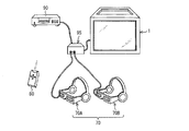
- FIG. 1 is a schematic configuration diagram of a 2D / 3D video viewing system including a display device according to the present embodiment. Sectional drawing of the display part of the display apparatus which concerns on this Embodiment is shown.
- the display device according to the present embodiment is a diagram illustrating an operation of allowing a 3D video viewer wearing liquid crystal shutter glasses to view a 3D video and a 2D video viewer to view a 2D video. It is a figure for demonstrating the operation
- the display device is a diagram illustrating an operation of allowing a 3D video viewer wearing liquid crystal shutter glasses to view a 3D video and a 2D video viewer to view a 2D video. It is a figure for demonstrating the operation
- FIG. 3 is a schematic configuration diagram of a 2D / 3D video viewing system including the display device 1.
- the parallax video that is played back by the recording / playback device 90 and displayed on the display device 1 is three-dimensionally displayed to the viewer wearing the liquid crystal shutter glasses (visual switching mechanism) 70.
- a video viewer hereinafter, sometimes referred to as “3D video” or “stereoscopic video” allows a viewer with a naked eye to view a two-dimensional video (hereinafter also referred to as “2D video”).
- the parallax video is a video using the parallax of the left and right eyes of the viewer, and means a right-eye video and a left-eye video dedicated to 3D video.
- the 2D / 3D video viewing system mainly includes the display device 1, liquid crystal shutter glasses (visual switching mechanism) 70, an operation unit 80, a recording / reproducing device 90, and a relay device 95. Is provided.
- the display device 1 displays an image reproduced by the recording / reproducing device 90, and is, for example, an LCD (liquid crystal display), a PDP (plasma display panel), or a CRT (cathode-ray tube) display.
- the display device 1 is provided with a parallax barrier (line-of-sight direction separation unit) 108 (not shown) in the display unit, the details of which will be described later with reference to FIG.
- the liquid crystal shutter glasses 70 have a three-layer structure of a polarizing plate, a liquid crystal filter, and a polarizing plate, and can switch between two transmitted polarized lights with the liquid crystal filter. More specifically, the liquid crystal shutter glasses 70 open and close the shutters for the left and right eyes by a shutter drive signal that controls passage and blocking of light, and the shutter drive signal is a desired video signal output from the display device 1. And the signal width corresponds to the video signal. Therefore, by opening and closing the shutter with this shutter drive signal, the viewer can view only the selected “video corresponding to one video signal” among the plurality of video signals in the shutter open state, and Other videos cannot be viewed with the shutter closed, and only desired videos can be viewed.
- the liquid crystal shutter glasses 70 are wired to the display device 1 via a relay 95 and a cable. However, the liquid crystal shutter glasses 70 may be wirelessly connected to the repeater 95 and / or the display device 1.
- liquid crystal shutter glasses 70A and 70B are connected to the repeater 95.
- the number of liquid crystal shutter glasses 70 is not limited to two, and may be one or a plurality other than three.
- the operation unit 80 is used by the viewer to input an instruction signal for operating the display device 1 and the recording / reproducing device 90.
- the operation unit 80 is provided in a remote control for remotely operating the display device 1 or the display device 1 itself.
- the operation buttons may be configured with a mouse or a keyboard connected to the display device 1.
- the instruction signal input by the viewer using the operation unit 80 is sent to each unit of the display device 1 and / or the recording / reproducing device 90 via an input / output control unit (not shown). Thereby, the viewer can operate the display device 1 and the recording / reproducing device 90.
- the operation unit 80 is also used to determine, change, confirm, and the like the viewing direction in which 3D video and / or 2D video is displayed by the parallax barrier 108 described later. That is, the viewer can input the display mode (2D / 3D) of the video that the viewer wants to watch and the line-of-sight direction in which the video is displayed to the display device 1 through the input operation via the operation unit 80. .
- the recording / reproducing apparatus 90 reproduces video information recorded on an information recording medium such as a BD (Blu-Ray (registered trademark) Disc), DVD (Digital Versatile Disc), HDD (Hard Disc Drive) or the like.
- an information recording medium such as a BD (Blu-Ray (registered trademark) Disc), DVD (Digital Versatile Disc), HDD (Hard Disc Drive) or the like.
- the recording / reproducing apparatus may be used.
- the video signal reproduced by the recording / reproducing device 90 is input to the display device 1.
- a video corresponding to video data received using a service for distributing content such as real-time broadcasting or a movie using an IP (Internet Protocol) network instead of the recording / reproducing device 90 is displayed on the display device 1.
- a service for distributing content such as real-time broadcasting or a movie using an IP (Internet Protocol) network instead of the recording / reproducing device 90 is displayed on the display device 1.
- IP Internet Protocol
- linear TV that is a broadcast-type service that distributes a program in real time according to a determined broadcast schedule, or content that is unicasted to the content processing device in response to a distribution request from the receiving side.
- a video corresponding to video data acquired using VoD (Video on Demand) as a service may be displayed on the display device 1.
- VoD Video on Demand
- the video displayed on the display device 1 is a 3D video and a 2D video (the right-eye video or the right-eye video or the right-eye video using left-eye video and parallax for the left and right eyes of the viewer).
- the present invention is not limited to these.
- the repeater 95 is for connecting the display device 1, the liquid crystal shutter glasses 70, and the recording / reproducing device 90 to each other.
- the repeater 95 is not particularly necessary when the liquid crystal shutter glasses 70 and the recording / reproducing device 90 are directly connected to the display device 1 or when the display device 1 and the liquid crystal shutter glasses 70 are wirelessly connected. .
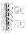
- FIG. 4 is a cross-sectional view of the display unit of the display device 1.
- the display unit 1 includes a liquid crystal panel 100, a backlight 101, a polarizing plate 102 installed on the backlight side of the liquid crystal panel, and a front surface on the light emitting direction side of the liquid crystal panel.
- a polarizing plate 103, a TFT (Thin Film Transistor) substrate 104, a liquid crystal layer 105, a color filter substrate 106, a glass substrate 107, and a parallax barrier 108 are provided.
- the liquid crystal panel 100 includes a pair of substrates having a liquid crystal layer 105 sandwiched between a TFT substrate 104 and a color filter substrate 106 disposed to face the TFT substrate 104, a parallax barrier 108 disposed on the front surface on the light emitting direction side, and a glass substrate. 107 is sandwiched between two polarizing plates 102 and 103, and is disposed slightly apart from the backlight 101.
- the liquid crystal panel 100 includes pixels composed of RGB colors (three primary colors).
- each pixel of the liquid crystal panel 100 is displayed separately for each of a plurality of viewing directions by the parallax barrier 108.
- the display device 1 is used for car navigation in which different images are displayed on the driver's seat and front passenger seat of an automobile, and each pixel of the liquid crystal panel 100 is shown on the left side of FIG. Display control is performed separately for display on the seat side and for display on the right side (driver's seat side).
- the display pixel on the left side is blocked from being displayed on the right side (driver seat side) by the parallax barrier 108 and is visible from the left side (passenger seat side).
- the display pixel on the right side is blocked from being displayed on the left side (passenger seat side) by the parallax barrier 108 and is visible from the right side (driver's seat side).
- the parallax barrier 108 can be configured to display different images in a plurality of directions such as three directions by changing the configuration of each pixel of the liquid crystal panel. Further, the parallax barrier 108 may be of various types such as a parallax method or a lenticular method. Furthermore, the parallax barrier 108 may be realized with a configuration that can be attached to and detached from the display unit of the display device 1 as long as alignment with each pixel of the liquid crystal panel 100 is possible.
- FIG. 1 is a block diagram for explaining the internal configuration of the display device 1.
- the display device 1 displays a 3D image for a viewer wearing the liquid crystal shutter glasses 70 and a video for viewing a 2D image for a viewer with naked eyes.
- the display device 1 includes at least a control unit 5 that performs overall control of each unit of the display device 1 and a signal (parallax) for displaying a parallax image on the display device 1 from an external recording / playback device 90 or an IP network, television radio waves, and the like.
- liquid crystal shutter glasses 70 and the operation unit 80 are communicably connected to the display device 1 by wire or wirelessly.
- the content receiving unit 40 receives a video signal reproduced by the recording / reproducing apparatus 90 or a video signal corresponding to video data received using a service for distributing content such as real-time broadcasting or a movie using an IP network. get. Then, the content receiving unit 40 outputs the video signal to the control unit 5. In the present embodiment, the content receiving unit 40 generates a parallax video signal for displaying parallax video (right-eye video and left-eye video) using the parallax of the left and right eyes of the viewer on the display device 1. It is assumed that it is acquired.
- the control unit 5 performs overall control of each unit of the display device 1 and includes a display control unit (display control unit) 10, a light amount control unit 20, and a synchronization control unit (synchronization control unit) 30.
- the display control unit 10 acquires a parallax video signal from the content reception unit 40. Then, the display control unit 10 controls the display of the parallax video displayed based on the parallax video signal displayed for each gaze direction separated by the liquid crystal shutter glasses 70 for each gaze direction. 3D video (stereoscopic video) can be viewed through the liquid crystal shutter glasses 70. At this time, the display control unit 10 controls the display of the parallax image displayed in the pixel group for each pixel group associated with the same line-of-sight direction among the plurality of line-of-sight directions.
- the right-eye image and the left-eye image that are parallax images are alternately displayed and correspond to the second line-of-sight direction different from the first line-of-sight direction.
- the video for the right eye or the video for the left eye is displayed.
- the display control unit 10 includes a pixel group determination unit (pixel group determination unit) 11, a video signal generation unit (video signal generation unit) 12, and a pixel group display control unit (pixel group display control unit). ) 13.
- the pixel group determination unit 11 includes a three-dimensional pixel group that is a pixel group in which a right-eye image and a left-eye image are alternately displayed, and a pixel group in which a right-eye image or a left-eye image is displayed. Each two-dimensional pixel group is determined.
- the pixel group determination unit 11 sets the 3D image to be displayed in the first viewing direction and the 2D image is displayed in the second viewing direction different from the first viewing direction.
- a two-dimensional pixel group and a two-dimensional pixel group are determined.
- the pixel group determination unit 11 can also determine a three-dimensional pixel group and a two-dimensional pixel group in response to an input operation by a viewer via the operation unit 80 described later. For example, based on an input operation such as changing the line-of-sight direction to the right side of the display device for a person who wants to view 3D video, and changing the line-of-sight direction to the left side of the display device for a person who wants to view parallax video (2D video). A three-dimensional pixel group and a two-dimensional pixel group can also be determined. Since the input operation method and operation screen by the viewer may be determined using a known technique, a detailed description thereof is omitted here.
- pixels corresponding to the three-dimensional pixel group and the two-dimensional pixel group among the pixels of the display unit 60 may be determined in advance.
- the video signal generation unit 12 is a three-dimensional pixel determined by the pixel group determination unit 11 based on the parallax video signal acquired from the content reception unit 40 or acquired from the content reception unit 40 via the pixel group determination unit 11.
- a three-dimensional video signal for displaying a parallax video by the group and a two-dimensional video signal for displaying the parallax video by the two-dimensional pixel group determined by the pixel group determination unit 11 are generated.
- the video signal generation unit 12 considers the ratio of the number of pixels of the display unit 60 to the number of pixels of the three-dimensional pixel group and the two-dimensional pixel group, the position of the three-dimensional pixel group, the two-dimensional pixel group, and the like. From the parallax video signal for displaying the parallax video on the display device 1, the three-dimensional video signal for displaying the parallax video on the three-dimensional pixel group, and the two-dimensional video for displaying the parallax video on the two-dimensional pixel group Generate a signal.
- the number of pixels required when displaying an image with a three-dimensional pixel group and a two-dimensional pixel group is a normal number that does not use the parallax barrier 108.
- Each is half of the video display.
- the video signal generation unit 12 performs the parallax between the three-dimensional pixel group and the two-dimensional pixel group so that the total number of pixels in the left-right direction (direction perpendicular to the gravity direction) of the display unit 60 is halved.
- a 3D video signal and a 2D video signal for displaying video are generated. Thereafter, the video signal generation unit 12 outputs the 3D video signal and the 2D video signal to the pixel group display control unit 13.
- the pixel group display control unit 13 displays the right-eye video and the left-eye video on the three-dimensional pixel group in accordance with the 3D video signal generated by the video signal generation unit 12, and the 2 2 generated by the video signal generation unit 12. According to the two-dimensional video signal, the right-eye video or the left-eye video is displayed on the two-dimensional pixel group.
- the light quantity control unit 20 includes a luminance control unit (first luminance control unit) 21 and a light transmittance control unit (light transmittance control unit) 22.
- the luminance control unit 21 is for controlling the luminance of the backlight included in the display device 1.
- a plurality of pixels of the display unit 60 are divided into a three-dimensional pixel group and a two-dimensional pixel group.
- the three-dimensional pixel group and the two-dimensional pixel group individual images whose display is controlled are displayed. For this reason, the amount of light in each pixel group is lower than in a normal display state (display state in which the parallax barrier 108 is not used).
- the light transmittance is lowered depending on the liquid crystal shutter glasses 70, and the amount of light felt by the viewer of the 3D video is further reduced. This becomes more significant as the line-of-sight direction separated by the parallax barrier 108 increases.
- the luminance control unit 21 performs control to increase the luminance of the backlight included in the display device 1, thereby increasing the amount of light felt by the viewer of the 3D video.
- the brightness control unit 21 may receive a command to increase the backlight brightness from the display control unit 10 and increase the backlight brightness in accordance with the command.
- the luminance control unit 21 may perform control to increase the luminance of the backlight according to the number of line-of-sight directions separated by the parallax barrier 108.
- the light transmittance control unit 22 is for controlling the light transmittance in the two-dimensional pixel group. Specifically, there are cases where the light intensity of the two-dimensional pixel group increases due to the luminance control unit 21 controlling the luminance of the three-dimensional pixel group. For example, when the luminance control unit 21 increases the luminance of the backlight, the same backlight is used in the two-dimensional pixel group, so that the amount of light increases too much for a 2D video viewer.
- the light transmittance control unit 22 has the light transmittance of the two-dimensional pixel group substantially equal to the light amount when the right-eye image or the left-eye image is displayed on the two-dimensional pixel group without using the parallax barrier 108.
- the amount of light felt by the viewer of the 2D video can be reduced by reducing the amount so as to be.
- the light transmittance control unit 22 may reduce the light transmittance in the two-dimensional pixel group when the luminance control unit 21 increases the luminance of the backlight. Alternatively, the light transmittance control unit 22 may perform control to reduce the light transmittance in the two-dimensional pixel group in accordance with the vertical fluctuation of the luminance level of the backlight controlled by the luminance control unit 21.
- the synchronization control unit 30 opens and closes the display timing when the pixel group display control unit 13 displays the right-eye image on the three-dimensional pixel group, and opens the right-eye liquid crystal shutter of the liquid crystal shutter glasses 70 and closes the left-eye liquid crystal shutter. Synchronize with timing. Further, the synchronization control unit 30 closes the display timing when the pixel group display control unit 13 displays the left-eye image on the three-dimensional pixel group, the right-eye liquid crystal shutter of the liquid crystal shutter glasses 70, and opens the left-eye liquid crystal shutter. Synchronize with the shutter opening and closing timing.
- the synchronization control unit 30 receives a display timing signal indicating the display timing for displaying the right-eye video and the left-eye video on the three-dimensional pixel group from the display control unit 10, and the liquid crystal is synchronized with the display timing. This is done by outputting a command to open / close the right eye liquid crystal shutter and the left eye liquid crystal shutter of the shutter glasses 70 to the command signal output unit 50.
- the command signal output unit 50 outputs a shutter drive signal that instructs the liquid crystal shutter glasses 70 to open and close the right eye liquid crystal shutter and the left eye liquid crystal shutter based on the display timing signal acquired from the synchronization control unit 30. Then, the liquid crystal shutter glasses 70 synchronize with the display timing at which the pixel group display control unit 13 displays the right-eye image on the three-dimensional pixel group based on the shutter drive signal, and the right-eye liquid crystal shutters of the liquid crystal shutter glasses 70. , The left-eye liquid crystal shutter is closed, and the pixel group display control unit 13 closes the right-eye liquid crystal shutter of the liquid crystal shutter glasses 70 in synchronization with the display timing at which the left-eye image is displayed on the three-dimensional pixel group. Open the left-eye LCD shutter.
- FIG. 2 is a block diagram for explaining the internal configuration of the display device 2.
- description is abbreviate
- the difference between the display device 1 and the display device 2 is that the light amount control unit 20 of the display device 1 includes a luminance control unit 21 and a light transmittance control unit 22, whereas the display device 2 has a light transmission property.
- the point by which the rate control part 22 is not included is mentioned.
- the plurality of pixels of the display unit 60 are divided into a three-dimensional pixel group and a two-dimensional pixel group, and in the three-dimensional pixel group and the two-dimensional pixel group, individual images whose display is controlled are displayed. For this reason, the amount of light in each pixel group is lower than in a normal display state (display state in which the parallax barrier 108 is not used).
- the light transmittance is lowered depending on the liquid crystal shutter glasses 70, and the amount of light felt by the viewer of the 3D video is further reduced. This becomes more significant as the line-of-sight direction separated by the parallax barrier 108 increases.
- the luminance control unit 23 performs control to increase the luminance of the three-dimensional pixel group.
- the luminance control unit 23 sets the average luminance of the two-dimensional pixel group to be lower than the average luminance of the three-dimensional pixel group, and sets the luminance in the two-dimensional pixel group to the normal display state (using the gaze direction separation unit). (The display state is not displayed) and is approximately equal to the amount of light. This eliminates the uncomfortable feeling experienced by viewers of 3D video and 2D video.
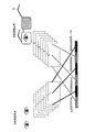
- FIGS. 5 and 6 show that a 3D video is displayed to a viewer wearing the liquid crystal shutter glasses 70 (hereinafter also referred to as “3D video viewer”), and a naked eye viewer (hereinafter, referred to as “3D video viewer”).
- FIG. 5 is a diagram illustrating an operation for viewing a 2D video
- FIG. 5 illustrates an operation in which no special processing is performed on the 2D video (right-eye video).
- FIG. 6 illustrates an operation of inserting a situation in which the pixel is black in the 2D video (right-eye video).
- the right-eye video and the left-eye video that can be used for the three-dimensional display are displayed on the display device 1, and the right-eye video and the right-eye video are displayed in the direction of the 3D video viewer by the parallax barrier 108.
- the left-eye video is alternately displayed, and the right-eye video is displayed in the direction of the 2D video viewer (may be the left-eye video). That is, the right eye image and the left eye image are displayed in the pixel group (three-dimensional pixel group) associated with the direction of the 3D image viewer, and the pixel group (two-dimensional image) associated with the direction of the 2D image viewer is displayed. The right eye image is displayed on the pixel group).
- the 2D video viewer views the right-eye video that is a 2D video with the left and right naked eyes
- the 3D video viewer views the right-eye video for the right eye and the left eye via the liquid crystal shutter glasses 70. Appreciate each video with your left eye.
- each of the plurality of viewers has different display modes of 2D video on one side and 3D video on the other side. Appreciating the video.
- a plurality of pixels of the display unit are divided into a three-dimensional pixel group and a two-dimensional pixel group, and individual images are displayed in each pixel group. Is halved compared to the normal display state (display state in which the parallax barrier 108 is not used). Moreover, since the light transmittance of the liquid crystal shutter glasses 70 is low, the amount of light felt by the 3D video viewer is further reduced. This becomes even more noticeable when individual images are displayed for three or more viewing directions by the parallax barrier. Therefore, in order to increase the amount of light felt by the 3D video viewer, the display device 1 increases the luminance of the backlight.
- the display device 1 uses the same backlight in the two-dimensional pixel group by increasing the brightness of the backlight, the amount of light increases too much for the 2D video viewer.
- FIG. 6 illustrates a method different from the configuration.
- a situation where the pixel is black (video) is inserted between successive right-eye video images, so that the luminance in the two-dimensional pixel group is set to a level at which a 2D video viewer can easily view the video image. Until adjusted.
- the video signal generation unit 12 outputs a low-luminance video signal for displaying a low-luminance video having a lower luminance than the right-eye video or the left-eye video displayed in the two-dimensional pixel group.
- the pixel group display control unit 13 displays the right-eye video or the left-eye video and the low-luminance video on the two-dimensional pixel group according to the two-dimensional video signal generated by the video signal generation unit 12.
- the right-eye video or the left-eye video and the low-luminance video may be alternately displayed, or may be displayed on the display unit 60 at an arbitrary ratio, which is felt by the 2D video viewer. If the amount of light can be reduced, it can be adjusted as appropriate.
- low-luminance video is described.
- the video does not have to be the video itself, and any configuration can be used as long as the luminance can be lower than that of the right-eye video or the left-eye video. It may be realized in a manner.
- the display device 1 (2) displays a parallax image using the parallax of the left and right eyes of the viewer, causes the viewer to view the stereoscopic video via the liquid crystal shutter glasses 70 that switches whether the right and left eyes are approved, and displays them.
- a display control unit 10 that enables viewing of stereoscopic images through the liquid crystal shutter glasses 70.
- the display control method displays a parallax image using the parallax of the left and right eyes of the viewer, allows the viewer to view the stereoscopic video via the liquid crystal shutter glasses 70 that switches between right and left eye viewing approval,
- the parallax image displayed on the display unit 60 provided in the display device 1 (2) is displayed separately in a plurality of viewing directions by the parallax barrier 108 provided in the display device 1 (2).
- a stereoscopic image can be viewed through the liquid crystal shutter glasses 70.
- the parallax barrier 108 displays the parallax image displayed on the display unit 60 separately in a plurality of viewing directions.
- the display control unit 10 performs display control on the parallax images displayed in the respective gaze directions separated by the parallax barrier 108 for each gaze direction. Accordingly, the display control unit 10 enables an appreciation mode in which a viewer can view a stereoscopic image through the liquid crystal shutter glasses 70 in addition to an appreciation mode in which the viewer views the parallax video without using the liquid crystal shutter glasses 70. To do.
- the display device 1 (2) (display control method) can display a stereoscopic image using the parallax of the right and left eyes, that is, a parallax barrier such as a parallax barrier. It is possible to solve the problem that there is no display device provided with.
- a parallax barrier such as a parallax barrier.
- each of the viewers is different. Since the video in the display mode can be viewed, the requests of a plurality of viewers can be satisfied at the same time.
- the parallax barrier 108 separates and displays the parallax images displayed on the display unit 60 in a plurality of viewing directions, so that there are three or more viewers. Even in such a case, the viewing mode desired by each viewer can be realized at the same time, and in this respect also, a more convenient display device is realized.
- the display unit 60 includes a plurality of pixels, and the display control unit 10 performs a pixel group associated with the same line-of-sight direction among the plurality of line-of-sight directions.
- the display control may be performed on the parallax image displayed on the pixel group.
- display control of parallax images is performed for each pixel group associated with the same line-of-sight direction. Therefore, the video according to the same display mode (3D video / 2D video) is displayed with respect to the same line-of-sight direction by display control for each pixel group, so that the viewing mode that the viewer does not desire is surely excluded. Can do. For example, when the viewer desires to view 2D video, only 2D video is displayed in the pixel group associated with the same viewing direction, and no 3D video is displayed in the viewing direction. Therefore, there is an effect of giving the viewer a sense of security without causing 3D sickness to the viewer located in the line-of-sight direction.
- the display control unit 10 alternately displays the right-eye video and the left-eye video, which are parallax images, in the pixel group associated with the first line-of-sight direction among the pixel groups.
- the pixel group associated with the second line-of-sight direction different from the first line-of-sight direction may be configured to display the right-eye video or the left-eye video.
- 3D video display is realized by alternately displaying a right-eye video and a left-eye video, which are parallax images using the parallax of the left and right eyes of the viewer. Further, when only one of the right-eye video and the left-eye video is displayed, a conventional 2D video is realized.
- the display control unit 10 realizes stereoscopic video display by alternately displaying the right-eye video and the left-eye video, which are parallax videos, in the pixel group associated with the first line-of-sight direction.
- 2D video display can be realized by displaying only either the right-eye video or the left-eye video.
- the display control unit 10 includes a three-dimensional pixel group that is a pixel group in which a right-eye image and a left-eye image are alternately displayed, and a right-eye image or a left-eye image.
- a pixel group determination unit 11 that determines a two-dimensional pixel group that is a pixel group on which an image is displayed, and the right-eye image and the left-eye image are displayed on the three-dimensional pixel group, and the right-eye image or the left-eye image is displayed.
- a pixel group display control unit 13 that displays an image on a two-dimensional pixel group.
- the pixel group determination unit 11 determines a three-dimensional pixel group in which a stereoscopic image is displayed and a two-dimensional pixel group in which a 2D image is displayed. For example, according to the setting that 3D video is displayed in the first line-of-sight direction and 2D video is displayed in the second line-of-sight direction different from the first line-of-sight direction, the pixel group determining unit 11 is configured to display 3D video. A two-dimensional pixel group and a two-dimensional pixel group are determined.
- the pixel group display control unit 13 displays the right-eye video and the left-eye video on the three-dimensional pixel group, and displays the right-eye video or the left-eye video on the two-dimensional pixel group. It is possible to view 3D video or 2D video.
- the display control unit 10 is used when a person who wants to watch 3D video composed of right-eye video and left-eye video and a person who wants to watch 2D video composed of right-eye video or left-eye video are mixed.
- each of the plurality of viewers it is possible to allow each of the plurality of viewers to view videos having different display modes, and to satisfy the requests of the plurality of viewers at the same time.
- the luminance control is performed so that the luminance of the three-dimensional pixel group is higher than the luminance of the three-dimensional pixel group when the right-eye video and the left-eye video are displayed without using the parallax barrier 108.
- the structure provided with a part may be sufficient.
- the plurality of pixels of the display unit 60 are divided into a three-dimensional pixel group and a two-dimensional pixel group, and individual images whose display is controlled in the three-dimensional pixel group and the two-dimensional pixel group, respectively.
- the amount of light in each pixel group is lower than in a normal display state (display state in which the parallax barrier 108 is not used).
- the light transmittance is lowered depending on the structure of the liquid crystal shutter glasses 70, and the amount of light felt by the viewer of the 3D video is further reduced. . This becomes more prominent as the line-of-sight direction separated by the liquid crystal shutter glasses 70 increases.
- the luminance control unit determines the luminance of the three-dimensional pixel group from the luminance of the three-dimensional pixel group when the right-eye video and the left-eye video are displayed without using the parallax barrier 108. Also make it high. As a result, the amount of light felt by the viewer of the 3D video can be increased, and the uncomfortable feeling experienced by the viewer can be eliminated.
- the luminance control unit 21 may be configured to increase the luminance of the backlight of the own device.
- the luminance control unit 21 increases the luminance of the backlight of the own device. Therefore, since the brightness of the three-dimensional pixel group can be increased, the amount of light felt by the viewer of the 3D video can be increased, and the uncomfortable feeling experienced by the viewer can be eliminated.
- the light transmittance in the two-dimensional pixel group is substantially equal to the light amount when the right-eye image or the left-eye image is displayed on the two-dimensional pixel group without using the parallax barrier 108. It may be the composition provided with the light transmittance control part 22 which decreases so that.
- the light intensity of the two-dimensional pixel group increases as the luminance control unit increases the luminance of the three-dimensional pixel group.
- the luminance control unit 21 increases the luminance of the backlight
- the same backlight is used in the two-dimensional pixel group, so that the amount of light increases too much for a 2D video viewer.
- the light transmittance control unit 22 sets the light transmittance in the two-dimensional pixel group to the right-eye image or the left-eye image without using the parallax barrier 108.
- the amount of light is reduced so as to be approximately equal to the amount of light used for display. Accordingly, since the amount of light in the two-dimensional pixel group can be reduced, the amount of light felt by the viewer of the 2D video can be reduced, and the uncomfortable feeling experienced by the viewer can be eliminated.
- the pixel group display control unit 13 reduces the luminance of the right-eye video or the left-eye video displayed in the two-dimensional pixel group lower than that of the right-eye video or the left-eye video.
- the configuration may be such that a luminance image is inserted and displayed on the two-dimensional pixel group.
- the luminance of the two-dimensional pixel group can be lowered on average. Therefore, it is possible to reduce the amount of light felt by the viewer of the 2D video image and to eliminate the uncomfortable feeling experienced by the viewer.
- low-luminance video is described.
- the video does not have to be the video itself, and any configuration can be used as long as the luminance can be lower than that of the right-eye video or the left-eye video. It may be realized with.
- the luminance control unit may be configured to increase the luminance of the three-dimensional pixel group.
- the luminance control unit increases the luminance of the three-dimensional pixel group itself, it is possible to increase the amount of light felt by the viewer of the 3D video and to eliminate the uncomfortable feeling experienced by the viewer.
- the luminance of the two-dimensional pixel group is substantially equal to the amount of light when the right-eye image or the left-eye image is displayed on the two-dimensional pixel group without using the parallax barrier 108.
- the configuration may include a luminance control unit 23 that reduces the luminance.
- the luminance control unit increases the luminance of the three-dimensional pixel group
- the light amount of the two-dimensional pixel group increases, and the amount of light may increase too much for a 2D video viewer.
- the luminance control unit 23 reduces the luminance of the two-dimensional pixel group so as to be substantially equal to the amount of light when the right-eye image or the left-eye image is displayed on the two-dimensional pixel group without using the parallax barrier 108.
- the brightness of the two-dimensional pixel group can be obtained.
- the amount of light felt by the viewer of the 2D video can be reduced, and the uncomfortable feeling experienced by the viewer can be eliminated.
- the display timing at which the pixel group display control unit 13 displays the right eye image on the three-dimensional pixel group are synchronized with the shutter opening / closing timing of opening the right-eye liquid crystal shutter and closing the left-eye liquid crystal shutter, and the pixel group display control unit 13 displays the left-eye image on the three-dimensional pixel group, and the right eye
- the configuration may include a synchronization control unit 30 that synchronizes the shutter opening / closing timing with the liquid crystal shutter closed and the left eye liquid crystal shutter opened.
- the synchronization control unit 30 suitably synchronizes the display timing when the pixel group display control unit 13 displays the right-eye video or the left-eye video on the three-dimensional pixel group and the shutter opening / closing timing of the liquid crystal shutter glasses. It is possible.
- the viewer can surely view the 3D image displayed on the three-dimensional pixel group via the liquid crystal shutter glasses 70.
- the pixel group determination unit 11 may be configured to determine the three-dimensional pixel group and the two-dimensional pixel group based on an input operation by the viewer via the operation unit 80.
- the pixel group determination unit 11 determines the three-dimensional pixel group and the two-dimensional pixel group based on an input operation by the viewer via the operation unit 80. Therefore, the direction of the line of sight is displayed on the right side of the display device 1 (2) for a person who wants to view a stereoscopic image (3D image), and the direction of the line of sight is displayed on the display device 1 (for a person who wants to view a parallax image (2D image).
- the embodiment of changing to the left side of 2) can be realized, and a more convenient display device can be realized.
- the parallax barrier 108 may be configured to be detachable from the display unit 60.
- the parallax barrier 108 is provided so as to be detachable from the display unit 60, the viewer only needs to remove the parallax barrier 108 when he or she wants to view only 2D video or only 3D video. In addition, it is possible to reliably realize a video display mode that meets the viewer's wishes.
- the display control method according to the present invention may be realized by a computer.
- a display control program for realizing the display control method by a computer by causing the computer to operate as a process, and recording the program are recorded.
- Computer-readable recording media are also within the scope of the present invention.
- each block of the display devices 1 and 2 in particular, the pixel group determination unit 11, the video signal generation unit 12, and the pixel group display control unit 13 may be configured by hardware logic, or as described below. It may be realized by software using
- the display device 1 or 2 includes a CPU (central processing unit) that executes instructions of a control program that realizes each function, a ROM (read only memory) that stores the program, and a RAM (random access memory that expands the program). ),
- a storage device (recording medium) such as a memory for storing the program and various data.
- An object of the present invention is a recording medium in which the program code (execution format program, intermediate code program, source program) of the control program of the display devices 1 and 2 which is software for realizing the functions described above is recorded so as to be readable by a computer. Can also be achieved by reading the program code recorded on the recording medium and executing it by the computer (or CPU or MPU).
- Examples of the recording medium include tapes such as magnetic tapes and cassette tapes, magnetic disks such as floppy (registered trademark) disks / hard disks, and disks including optical disks such as CD-ROM / MO / MD / DVD / CD-R.
- Card system such as IC card, IC card (including memory card) / optical card, or semiconductor memory system such as mask ROM / EPROM / EEPROM / flash ROM.
- the display devices 1 and 2 may be configured to be connectable to a communication network, and the program code may be supplied via the communication network.
- the communication network is not particularly limited.
- the Internet intranet, extranet, LAN, ISDN, VAN, CATV communication network, virtual private network, telephone line network, mobile communication network, satellite communication. A net or the like is available.
- the transmission medium constituting the communication network is not particularly limited. For example, even in the case of wired such as IEEE 1394, USB, power line carrier, cable TV line, telephone line, ADSL line, etc., infrared rays such as IrDA and remote control, Bluetooth (Registered trademark), 802.11 wireless, HDR, mobile phone network, satellite line, terrestrial digital network, and the like can also be used.
- the present invention can also be realized in the form of a computer data signal embedded in a carrier wave in which the program code is embodied by electronic transmission.
- the left and right eyes of a viewer who views the display screen through a visual control mechanism provided with a means for switching between viewing approval and disapproval in each of the left and right eyes in conjunction with the display screen.
- a 3D video display device using parallax having a line-of-sight separation unit (parallax barrier) and a unit for individually controlling an image to be displayed toward each line of sight separated by the line-of-sight separation unit. Also good.
- the brightness of the 3D video display is increased as compared with the case where the 3D video display is performed without using the line-of-sight separation unit.
- the structure which has this may be sufficient.
- the display device according to the present invention may be a 3D video display device provided with a liquid crystal, and the above-described means for increasing the brightness may perform a control for increasing the brightness of the backlight for image display.
- the display device is a 3D video display device provided with a self-luminous element for image display, and the means for increasing the brightness is a control for increasing the brightness of the pixel for displaying the 3D image itself. It may be the composition which performs.
- the display device is for 2D display so that when 2D video display is performed using the line-of-sight separation means, the amount of light is substantially equal to that when 2D video display is performed without using the line-of-sight separation means. It may be configured to perform control to reduce the transmittance of the dots of the pixels.
- the display device is for 2D display so that when 2D video display is performed using the line-of-sight separation means, the amount of light is substantially equal to that when 2D video display is performed without using the line-of-sight separation means. It may be configured to perform control to increase the luminance of the pixels.
- the display device can be applied to various uses.
- a car navigation system a mobile phone, and a PDA (PDA (displaying different images) on a television set at home, a driver seat and a passenger seat of a car.
- PDA PDA
- PCs personal digital assistants
- television receivers but also to measuring devices, medical devices, industrial devices, and the like.
- a 3D motion sickness may be caused by viewing a 3D image using parallax between the left and right eyes. Or there are many people with disabilities in one eye, those who do not have 3D ornamental glasses, those who cannot buy expensive 3D glasses, and those who find it cumbersome to wear 3D ornamental glasses. . Such a person naturally desires to view 2D video instead of 3D video. Then, when there are a plurality of viewers, there are cases where a person who wants to watch 2D video and a person who wants to watch 3D video are mixed.
- the present invention has been made in view of the above-described conventional problems, and in a display device that allows a viewer to view a stereoscopic image via a visual switching mechanism that switches between right and left eye approval / disapproval, using an image separation unit
- Another object of the present invention is to realize a display device, a display control method, a display control program, and a computer-readable recording medium that allow each of a plurality of viewers to view images having different display modes.
- the display unit includes a plurality of pixels, and the display control unit is configured for each pixel group associated with the same line-of-sight direction among the plurality of line-of-sight directions.
- the display control may be performed on the parallax image displayed on the pixel group.
- display control of parallax images is performed for each pixel group associated with the same line-of-sight direction. Therefore, the video according to the same display mode (3D video / 2D video) is displayed with respect to the same line-of-sight direction by display control for each pixel group, so that the viewing mode that the viewer does not desire is surely excluded. Can do. For example, when the viewer desires to view 2D video, only 2D video is displayed in the pixel group associated with the same viewing direction, and no 3D video is displayed in the viewing direction. Therefore, there is an effect of giving the viewer a sense of security without causing 3D sickness to the viewer located in the line-of-sight direction.
- the display control unit alternately displays the right-eye video and the left-eye video, which are parallax images, in the pixel group associated with the first line-of-sight direction among the pixel groups.
- the right eye image or the left eye image may be displayed in the pixel group that is displayed and associated with the second line-of-sight direction different from the first line-of-sight direction.
- 3D video display is realized by alternately displaying a right-eye video and a left-eye video, which are parallax images using the parallax of the left and right eyes of the viewer. Further, when only one of the right-eye video and the left-eye video is displayed, a conventional 2D video is realized.
- the display control means realizes stereoscopic video display by alternately displaying the right-eye video and the left-eye video, which are parallax videos, in the pixel group associated with the first line-of-sight direction.
- 2D video display can be realized by displaying only either the right-eye video or the left-eye video.
- the display control means includes a three-dimensional pixel group that is a pixel group in which the right-eye video and the left-eye video are alternately displayed, and the right-eye pixel.
- a pixel group determining means for respectively determining a two-dimensional pixel group that is a pixel group on which the video or the left-eye video is displayed; and displaying the right-eye video and the left-eye video on the three-dimensional pixel group,
- a pixel group display control unit that displays the video or the left-eye video on the two-dimensional pixel group.
- the pixel group determining means determines the three-dimensional pixel group on which the stereoscopic video is displayed and the two-dimensional pixel group on which the 2D video is displayed. This is because, for example, the 3D image is displayed in the first line-of-sight direction, and the 2D image is displayed in the second line-of-sight direction different from the first line-of-sight direction. A pixel group and a two-dimensional pixel group are determined.
- the pixel group display control means displays the right-eye video and the left-eye video on the three-dimensional pixel group, and displays the right-eye video or the left-eye video on the two-dimensional pixel group.
- the viewers can view 3D video and 2D video, respectively.
- the display control means includes a person who wants to watch the 3D video composed of the right eye video and the left eye video and a person who wants to watch the 2D video composed of the right eye video or the left eye video.
- the display control means includes a person who wants to watch the 3D video composed of the right eye video and the left eye video and a person who wants to watch the 2D video composed of the right eye video or the left eye video.
- the luminance of the three-dimensional pixel group is determined from the luminance of the three-dimensional pixel group when the right-eye video and the left-eye video are displayed without using the line-of-sight direction separation unit.
- the first luminance control means for increasing the brightness may be provided.
- the plurality of pixels of the display unit are divided into a three-dimensional pixel group and a two-dimensional pixel group, and in the three-dimensional pixel group and the two-dimensional pixel group, individual images whose display is controlled are respectively displayed. Since it is displayed, the amount of light in each pixel group is lower than in a normal display state (display state in which the line-of-sight direction separation unit is not used). In addition, since the viewer of the 3D video views the 3D video via the visual switching mechanism, the light transmittance is lowered depending on the structure of the visual switching mechanism, and the amount of light felt by the viewer of the 3D video is further reduced. This becomes more significant as the line-of-sight direction separated by the visual switching mechanism increases.
- the first luminance control unit displays the luminance of the three-dimensional pixel group for the right-eye video and the left-eye video without using the gaze direction separation unit.
- the luminance is set higher than that of the three-dimensional pixel group.
- the first luminance control means may be configured to increase the luminance of the backlight of the device itself.
- the first luminance control means increases the luminance of the backlight of the own device. Therefore, since the brightness of the three-dimensional pixel group can be increased, the amount of light felt by the viewer of the 3D video can be increased, and the uncomfortable feeling experienced by the viewer can be eliminated.
- the display device when the light transmittance in the two-dimensional pixel group is displayed on the two-dimensional pixel group, the right-eye image or the left-eye image is displayed on the two-dimensional pixel group without using the line-of-sight direction separation unit. It may be configured to include a light transmittance control means for reducing the light amount so as to be substantially equal to the amount of light.
- the first luminance control means increases the luminance of the three-dimensional pixel group, so that the amount of light of the two-dimensional pixel group increases.
- the first luminance control means increases the luminance of the backlight, since the same backlight is used in the two-dimensional pixel group, the amount of light increases too much for the 2D video viewer.
- the light transmittance control unit is configured to calculate the light transmittance of the two-dimensional pixel group using the right-eye image or the left-eye image without using the line-of-sight direction separation unit.
- the amount of light is reduced so as to be substantially equal to the amount of light when displayed on the dimensional pixel group. Accordingly, since the amount of light in the two-dimensional pixel group can be reduced, the amount of light felt by the viewer of the 2D video can be reduced, and the uncomfortable feeling experienced by the viewer can be eliminated.
- the pixel group display control means has a brightness higher than the right-eye video or the left-eye video in the right-eye video or the left-eye video displayed on the two-dimensional pixel group.
- the low-luminance video with a low level may be inserted and displayed on the two-dimensional pixel group.
- the luminance of the two-dimensional pixel group is lowered on average. Can do. Therefore, it is possible to reduce the amount of light felt by the viewer of the 2D video image and to eliminate the uncomfortable feeling experienced by the viewer.
- low luminance video in the above, it is not necessary to be the video itself, and the above configuration can be used as long as it can create a lower luminance than the right eye video or the left eye video. May be implemented in any manner.
- the first luminance control means may be configured to increase the luminance of the three-dimensional pixel group.
- the first luminance control unit increases the luminance of the three-dimensional pixel group itself, the amount of light felt by the viewer of the 3D video can be increased, and the uncomfortable feeling experienced by the viewer can be eliminated. Play.
- the luminance of the two-dimensional pixel group is determined based on the amount of light when the right-eye image or the left-eye image is displayed on the two-dimensional pixel group without using the line-of-sight direction separation unit.
- a configuration may be provided that includes second luminance control means for reducing the brightness so as to be substantially equal.
- the first luminance control means increases the luminance of the three-dimensional pixel group
- the light amount of the two-dimensional pixel group increases, and the amount of light may increase too much for a 2D video viewer.
- the second luminance control means approximates the luminance of the two-dimensional pixel group to the amount of light when the right-eye image or the left-eye image is displayed on the two-dimensional pixel group without using the line-of-sight direction separation unit.
- the brightness of the two-dimensional pixel group can be increased by reducing the values to be equal. As a result, the amount of light felt by the viewer of the 2D video can be reduced, and the uncomfortable feeling experienced by the viewer can be eliminated.
- the pixel group display control means adds the right-eye to the three-dimensional pixel group.
- the display timing for displaying the video for the image and the shutter opening / closing timing for opening the liquid crystal shutter for the right eye and closing the liquid crystal shutter for the left eye are synchronized, and the pixel group display control means is synchronized with the three-dimensional pixel group.
- the synchronization control means preferably has a display timing when the pixel group display control means displays the right-eye video or the left-eye video on the three-dimensional pixel group, and a shutter opening / closing timing of the liquid crystal shutter glasses. It is possible to synchronize.
- the viewer can surely view the 3D image displayed on the three-dimensional pixel group via the liquid crystal shutter glasses.
- the pixel group determining means may determine the three-dimensional pixel group and the two-dimensional pixel group based on an input operation by the viewer via an operation unit. .
- the pixel group determining means determines the three-dimensional pixel group and the two-dimensional pixel group based on an input operation by the viewer via the operation unit. Therefore, the direction of the line of sight is changed to the right side of the display device for a person who wants to view a stereoscopic image (3D image), and the direction of the line of sight is changed to the left side of the display device for a person who wants to view a parallax image (2D image).
- 3D image stereoscopic image
- 2D image parallax image
- the line-of-sight direction separation unit may be configured to be detachable from the display unit.
- the line-of-sight direction separation unit Since the line-of-sight direction separation unit is detachably attached to the display unit, the viewer can remove the line-of-sight direction separation unit when only viewing 2D video or viewing only 3D video. What is necessary is just to implement
- the display control method may be realized by a computer.
- a display control program for realizing the display control method by the computer by causing the computer to operate as the process, and a computer recording the same A readable recording medium falls within the scope of the present invention.
- the present invention relates to a display device that allows a viewer to view a stereoscopic image via a visual switching mechanism that switches between right and left eye viewing approval / disapproval, and is different for each of a plurality of viewers using video separation means such as a parallax barrier.
- the present invention relates to a display device capable of viewing an image of a display mode, and can be suitably applied to a liquid crystal display device or a self-luminous display device such as plasma.
- Display device 5 Control unit 10 Display control unit (display control means) 11 Pixel group determination unit (pixel group determination means) 12 Video signal generator (video signal generator) 13 Pixel group display control unit (pixel group display control means) 20 Light quantity control unit 21 Luminance control unit (first luminance control means) 22 Light transmittance control unit (light transmittance control means) 23 Luminance control unit (second luminance control means) 30 synchronization control unit (synchronous control means) 40 Content Receiving Unit 50 Command Signal Output Unit 60 Display Unit 70 / 70A / 70B Liquid Crystal Shutter Glasses (Visual Switching Mechanism) 80 Operation unit 90 Recording / reproducing device 95 Repeater 100 Liquid crystal panel 101 Backlight 102/103 Polarizing plate 104 TFT substrate 105 Liquid crystal layer 106 Color filter substrate 107 Glass substrate 108 Parallax barrier (line-of-sight direction separation unit)
Landscapes
- Engineering & Computer Science (AREA)
- Physics & Mathematics (AREA)
- Multimedia (AREA)
- Signal Processing (AREA)
- General Physics & Mathematics (AREA)
- Optics & Photonics (AREA)
- Computer Hardware Design (AREA)
- Theoretical Computer Science (AREA)
- Testing, Inspecting, Measuring Of Stereoscopic Televisions And Televisions (AREA)
- Controls And Circuits For Display Device (AREA)
Abstract
Description
自動または観賞者による入力操作によって上記表示装置の表示部の画素のうち、3次元映像用の3次元画素群と2次元映像用の2次元画素群とをそれぞれ決定する画素決定手段と、上記3次元画素群および2次元画素群をそれぞれ表示制御する画素群表示制御手段と、パララックス方式またはレンティキュラ方式の視差バリアと、を備える構成である。
表示装置1の説明に入る前に、表示装置1を含む2D/3D映像観賞システムを図3により説明する。図3は、表示装置1を含む2D/3D映像観賞システムの概略構成図である。
次に、表示装置1の表示部に設けられる視差バリアについて図4を参照して説明する。図4は、表示装置1の表示部の断面図を示す。
次に、液晶表示装置1の内部構成を図1により説明する。図1は、表示装置1の内部構成を説明するためのブロック図である。
次に、画素が自発光するプラズマ等の自発光型の表示装置2の内部構成を図2により説明する。図2は、表示装置2の内部構成を説明するためのブロック図である。なお、図1を参照して説明した内容については説明を省略する。
次に、2人の観賞者が3D映像および2D映像をそれぞれ観賞する動作を図5、図6により説明する。図5、図6は、表示装置1が、液晶シャッターメガネ70を装着する観賞者(以降、「3D映像観賞者」と称する場合もある。)には3D映像を、裸眼の観賞者(以降、「2D映像観賞者」と称する場合もある。)には2D映像を観賞させる動作を示す図であり、図5は、2D映像(右目用映像)に対して特段の処理を行わない動作を、図6は、2D映像(右目用映像)に画素が黒となる状況を挿入する動作をそれぞれ表す。
以下、表示装置1・2によって得られる効果を説明する。
〔その他〕
本発明に係る表示装置は、表示画面に連動して、左右の目各々における視認可否の切り替えを行う手段が設けられた視覚制御機構を透して表示画面を視聴する視聴者の左右の目の視差を利用した3D映像表示装置であって、視線分離手段(視差バリア)と、上記視線分離手段によって分離される各視線に向けて表示する画像を個別に制御する手段とを有する構成であってもよい。
〔その他2〕
ここで、補足的に、上記特許文献1、2の技術的課題を述べておく。
5 制御部
10 表示制御部(表示制御手段)
11 画素群決定部(画素群決定手段)
12 映像信号生成部(映像信号生成手段)
13 画素群表示制御部(画素群表示制御手段)
20 光量制御部
21 輝度制御部(第1輝度制御手段)
22 光透過率制御部(光透過率制御手段)
23 輝度制御部(第2輝度制御手段)
30 同期制御部(同期制御手段)
40 コンテンツ受信部
50 命令信号出力部
60 表示部
70・70A・70B 液晶シャッターメガネ(視認切替機構)
80 操作部
90 記録再生装置
95 中継器
100 液晶パネル
101 バックライト
102・103 偏光板
104 TFT基板
105 液晶層
106 カラーフィルタ基板
107 ガラス基板
108 視差バリア(視線方向分離部)
Claims (18)
- 観賞者の左右の目の視差を利用した3次元映像と、2次元映像の表示が可能な表示装置であって、
自動または観賞者による入力操作によって上記表示装置の表示部の画素のうち、3次元映像用の3次元画素群と2次元映像用の2次元画素群とをそれぞれ決定する画素決定手段と、
上記3次元画素群および2次元画素群をそれぞれ表示制御する画素群表示制御手段と、
パララックス方式またはレンティキュラ方式の視差バリアと、
を備えることを特徴とする表示装置。 - 2次元映像および3次元映像を表示する際に、バックライト輝度を高くするとともに、2次元画素群の光透過率を下げる光量制御手段を有することを特徴とする請求項1に記載の表示装置。
- 観賞者の左右の目の視差を利用した視差映像を表示し、左右の目の視認可否を切り替える視認切替機構を介して観賞者に立体映像を観賞させる表示装置であって、
表示部に表示される視差映像を複数の視線方向に分離して表示させる視線方向分離部と、
上記視線方向分離部によって分離された各視線方向に向けて表示される視差映像を、視線方向毎に表示制御し、上記視認切替機構を介した立体映像の観賞を可能にする表示制御手段と、を備えることを特徴とする表示装置。 - 上記表示部は、複数の画素を有しており、
上記表示制御手段は、上記複数の視線方向のうち、同一の視線方向に対応付けられた画素群ごとに、その画素群に表示される視差映像を表示制御することを特徴とする請求項3に記載の表示装置。 - 上記表示制御手段は、上記画素群のうち、第1の視線方向に対応付けられた画素群では、視差映像である右目用映像および左目用映像を交互に表示させ、上記第1の視線方向とは異なる第2の視線方向に対応付けられた画素群では、上記右目用映像または上記左目用映像を表示させることを特徴とする請求項4に記載の表示装置。
- 上記表示制御手段は、
上記画素群のうち、上記右目用映像および上記左目用映像が交互に表示される画素群である3次元画素群、及び上記右目用映像または上記左目用映像が表示される画素群である2次元画素群をそれぞれ決定する画素群決定手段と、
上記右目用映像および上記左目用映像を上記3次元画素群に表示させ、上記右目用映像または上記左目用映像を上記2次元画素群に表示させる画素群表示制御手段と、
を備えることを特徴とする請求項5に記載の表示装置。 - 上記3次元画素群の輝度を、上記視線方向分離部を用いることなく上記右目用映像および上記左目用映像を表示するときの当該3次元画素群の輝度よりも高くする第1輝度制御手段を備えることを特徴とする請求項6に記載の表示装置。
- 上記第1輝度制御手段は、自装置のバックライトの輝度を高くすることを特徴とする請求項7に記載の表示装置。
- 上記2次元画素群における光の透過率を、上記視線方向分離部を用いることなく上記右目用映像または上記左目用映像を当該2次元画素群に表示するときの光量と略等しくなるように低下させる光透過率制御手段を備えることを特徴とする請求項7または8に記載の表示装置。
- 上記画素群表示制御手段は、上記2次元画素群に表示される上記右目用映像または上記左目用映像に、当該右目用映像または当該左目用映像よりも輝度の低い低輝度映像を挿入して上記2次元画素群に表示させることを特徴とする請求項7から9の何れか1項に記載の表示装置。
- 上記第1輝度制御手段は、上記3次元画素群の輝度を高くすることを特徴とする請求項7に記載の表示装置。
- 上記2次元画素群の輝度を、上記視線方向分離部を用いることなく上記右目用映像または上記左目用映像を当該2次元画素群に表示するときの光量と略等しくなるように低下させる第2輝度制御手段を備えることを特徴とする請求項7から11の何れか1項に記載の表示装置。
- 上記視認切替機構が、右目用液晶シャッターおよび左目用液晶シャッターを有する液晶シャッターメガネであるときに、
上記画素群表示制御手段が上記3次元画素群に上記右目用映像を表示させる表示タイミングと、上記右目用液晶シャッターを開、上記左目用液晶シャッターを閉とするシャッター開閉タイミングとを同期させ、かつ、上記画素群表示制御手段が上記3次元画素群に上記左目用映像を表示させる表示タイミングと、上記右目用液晶シャッターを閉、上記左目用液晶シャッターを開とするシャッター開閉タイミングとを同期させる同期制御手段を備えることを特徴とする請求項6から11の何れか1項に記載の表示装置。 - 上記画素群決定手段は、操作部を介した上記観賞者による入力操作に基づき、上記3次元画素群および上記2次元画素群を決定することを特徴とする請求項6から12の何れか1項に記載の表示装置。
- 上記視線方向分離部は、上記表示部に対して着脱可能に設けられていることを特徴とする請求項3から13の何れか1項に記載の表示装置。
- 観賞者の左右の目の視差を利用した視差映像を表示し、左右の目の視認可否を切り替える視認切替機構を介して観賞者に立体映像を観賞させる表示制御方法であって、
表示装置に設けられた表示部に表示される視差映像を、当該表示装置に設けられた視線方向分離部により複数の視線方向に分離して表示し、
上記視線方向分離部によって分離された各視線方向に向けて表示される視差映像を、視線方向毎に表示制御することで、上記視認切替機構を介した立体映像の観賞を可能にすることを特徴とする表示制御方法。 - 請求項16に記載の表示制御方法における、視差映像を視線方向毎に表示制御する処理を、コンピュータに実行させるための表示制御プログラム。
- 請求項17に記載の表示制御プログラムを記録したコンピュータ読み取り可能な記録媒体。
Priority Applications (2)
| Application Number | Priority Date | Filing Date | Title |
|---|---|---|---|
| US13/814,267 US20130128019A1 (en) | 2010-08-09 | 2011-08-04 | Display device, display control method, display control program, and computer readable recording medium |
| CN201180038677.9A CN103069820B (zh) | 2010-08-09 | 2011-08-04 | 显示装置及显示控制方法 |
Applications Claiming Priority (2)
| Application Number | Priority Date | Filing Date | Title |
|---|---|---|---|
| JP2010-178544 | 2010-08-09 | ||
| JP2010178544A JP5053427B2 (ja) | 2010-08-09 | 2010-08-09 | 表示装置 |
Publications (1)
| Publication Number | Publication Date |
|---|---|
| WO2012020695A1 true WO2012020695A1 (ja) | 2012-02-16 |
Family
ID=45567664
Family Applications (1)
| Application Number | Title | Priority Date | Filing Date |
|---|---|---|---|
| PCT/JP2011/067890 Ceased WO2012020695A1 (ja) | 2010-08-09 | 2011-08-04 | 表示装置、表示制御方法、表示制御プログラム、及びコンピュータ読み取り可能な記録媒体 |
Country Status (4)
| Country | Link |
|---|---|
| US (1) | US20130128019A1 (ja) |
| JP (1) | JP5053427B2 (ja) |
| CN (1) | CN103069820B (ja) |
| WO (1) | WO2012020695A1 (ja) |
Cited By (1)
| Publication number | Priority date | Publication date | Assignee | Title |
|---|---|---|---|---|
| WO2020173055A1 (zh) * | 2019-02-28 | 2020-09-03 | 未艾医疗技术(深圳)有限公司 | VRDS 4D医学影像多设备Ai联动显示方法及产品 |
Families Citing this family (15)
| Publication number | Priority date | Publication date | Assignee | Title |
|---|---|---|---|---|
| WO2012144453A1 (ja) * | 2011-04-22 | 2012-10-26 | シャープ株式会社 | 表示装置 |
| WO2013058158A1 (ja) * | 2011-10-18 | 2013-04-25 | シャープ株式会社 | 表示制御回路、それを備えた液晶表示装置、および表示制御方法 |
| JP5351311B1 (ja) * | 2012-06-29 | 2013-11-27 | 株式会社ソニー・コンピュータエンタテインメント | 立体映像観察デバイスおよび透過率制御方法 |
| JP6024617B2 (ja) * | 2013-08-15 | 2016-11-16 | 富士ゼロックス株式会社 | 情報処理装置及び情報処理プログラム |
| KR102142250B1 (ko) * | 2013-08-30 | 2020-08-07 | 엘지디스플레이 주식회사 | 입체영상 표시장치 및 이의 구동방법 |
| KR102233116B1 (ko) * | 2013-12-31 | 2021-03-29 | 엘지디스플레이 주식회사 | 입체 영상 디스플레이 장치와 이의 구동 방법 |
| EP2894508A1 (en) * | 2013-12-31 | 2015-07-15 | Thomson Licensing | Method for displaying a content through either a head mounted display device or a display device, corresponding head mounted display device and computer program product |
| JP2016109434A (ja) * | 2014-12-02 | 2016-06-20 | アルパイン株式会社 | 電子機器 |
| KR20160089600A (ko) * | 2015-01-19 | 2016-07-28 | 삼성디스플레이 주식회사 | 표시 장치 |
| CN108370062B (zh) | 2015-12-25 | 2021-01-29 | 富士胶片株式会社 | 全固态二次电池及制造方法 |
| KR102632795B1 (ko) * | 2016-09-21 | 2024-02-02 | 삼성전자주식회사 | 컨텐츠와 연관된 네비게이터 표시 방법 및 이를 구현한 전자 장치 |
| DE102019205593A1 (de) * | 2019-04-17 | 2020-10-22 | Fresenius Medical Care AG & Co. KGaA | Vorrichtung und Verfahren zur gleichzeitigen Darstellung unterschiedlicher Inhalte auf einer Anzeige eines medizintechnischen Geräts |
| CN112188181B (zh) * | 2019-07-02 | 2023-07-04 | 中强光电股份有限公司 | 图像显示设备、立体图像处理电路及其同步信号校正方法 |
| CN114430483A (zh) * | 2021-12-16 | 2022-05-03 | 泛太通信导航(珠海)有限公司 | 3d视觉无人车监视系统及相应无人车 |
| JP2024095442A (ja) * | 2022-12-28 | 2024-07-10 | 株式会社ジャパンディスプレイ | 表示装置及び表示システム |
Citations (3)
| Publication number | Priority date | Publication date | Assignee | Title |
|---|---|---|---|---|
| JPH06311536A (ja) * | 1993-04-23 | 1994-11-04 | Sanyo Electric Co Ltd | 立体映像表示装置及び立体映像表示用アダプタ |
| JPH0973049A (ja) * | 1995-06-29 | 1997-03-18 | Canon Inc | 画像表示方法及びそれを用いた画像表示装置 |
| JP2010503888A (ja) * | 2006-09-19 | 2010-02-04 | コーニンクレッカ フィリップス エレクトロニクス エヌ ヴィ | 複数の個別設定を用いた画像観察 |
Family Cites Families (3)
| Publication number | Priority date | Publication date | Assignee | Title |
|---|---|---|---|---|
| KR100869673B1 (ko) * | 2004-11-30 | 2008-11-21 | 후지쓰 텐 가부시키가이샤 | 표시제어장치 및 표시장치 |
| JP4979136B2 (ja) * | 2008-06-03 | 2012-07-18 | Necカシオモバイルコミュニケーションズ株式会社 | 放送受信端末装置及びプログラム |
| JP4386299B1 (ja) * | 2008-10-09 | 2009-12-16 | 健治 吉田 | パララックスバリア、裸眼立体映像表示装置 |
-
2010
- 2010-08-09 JP JP2010178544A patent/JP5053427B2/ja not_active Expired - Fee Related
-
2011
- 2011-08-04 CN CN201180038677.9A patent/CN103069820B/zh not_active Expired - Fee Related
- 2011-08-04 WO PCT/JP2011/067890 patent/WO2012020695A1/ja not_active Ceased
- 2011-08-04 US US13/814,267 patent/US20130128019A1/en not_active Abandoned
Patent Citations (3)
| Publication number | Priority date | Publication date | Assignee | Title |
|---|---|---|---|---|
| JPH06311536A (ja) * | 1993-04-23 | 1994-11-04 | Sanyo Electric Co Ltd | 立体映像表示装置及び立体映像表示用アダプタ |
| JPH0973049A (ja) * | 1995-06-29 | 1997-03-18 | Canon Inc | 画像表示方法及びそれを用いた画像表示装置 |
| JP2010503888A (ja) * | 2006-09-19 | 2010-02-04 | コーニンクレッカ フィリップス エレクトロニクス エヌ ヴィ | 複数の個別設定を用いた画像観察 |
Cited By (1)
| Publication number | Priority date | Publication date | Assignee | Title |
|---|---|---|---|---|
| WO2020173055A1 (zh) * | 2019-02-28 | 2020-09-03 | 未艾医疗技术(深圳)有限公司 | VRDS 4D医学影像多设备Ai联动显示方法及产品 |
Also Published As
| Publication number | Publication date |
|---|---|
| US20130128019A1 (en) | 2013-05-23 |
| CN103069820B (zh) | 2015-04-08 |
| JP5053427B2 (ja) | 2012-10-17 |
| CN103069820A (zh) | 2013-04-24 |
| JP2012039443A (ja) | 2012-02-23 |
Similar Documents
| Publication | Publication Date | Title |
|---|---|---|
| JP5053427B2 (ja) | 表示装置 | |
| TWI477149B (zh) | 具有複數視圖之顯示裝置、方法、系統及媒體 | |
| US8988513B2 (en) | Method and system for time-multiplexed shared display | |
| US9285599B2 (en) | Three-dimensional video viewing system, display system, optical shutter, and three-dimensional video viewing method | |
| CN102256146B (zh) | 三维图像显示装置及其驱动方法 | |
| JP5909448B2 (ja) | 二次元兼用三次元映像ディスプレイ装置及びその駆動方法 | |
| CN102089800B (zh) | 图像显示设备、用于图像观察的眼镜以及图像显示控制方法 | |
| US20110221871A1 (en) | Display device and audiovisual device | |
| US8760504B2 (en) | Shutter glasses, and electronic apparatus and method for adjusting ambient brightness received by shutter glasses operative under two-dimensional image viewing mode | |
| JP5573682B2 (ja) | 立体映像鑑賞システム、表示システム、光シャッタおよび立体映像鑑賞方法 | |
| US20110164118A1 (en) | Display apparatuses synchronized by one synchronization signal | |
| US20110248989A1 (en) | 3d display apparatus, method for setting display mode, and 3d display system | |
| US20110149052A1 (en) | 3d image synchronization apparatus and 3d image providing system | |
| Hutchison et al. | The design and implementation of a stereoscopic microdisplay television | |
| US9253478B2 (en) | Information processing method and information processing device | |
| JP2012178836A (ja) | 表示装置、表示制御方法、表示制御プログラム、及びコンピュータ読み取り可能な記録媒体 | |
| KR101078768B1 (ko) | 다종영상물 동시 시청하기 위한 디스플레이 방법 및 시스템 | |
| McCormick et al. | Implementation of stereoscopic and dualview images on a micro-display high definition television | |
| CN103051907A (zh) | 一种3d快门眼镜、显示装置、显示方法及系统 |
Legal Events
| Date | Code | Title | Description |
|---|---|---|---|
| WWE | Wipo information: entry into national phase |
Ref document number: 201180038677.9 Country of ref document: CN |
|
| 121 | Ep: the epo has been informed by wipo that ep was designated in this application |
Ref document number: 11816361 Country of ref document: EP Kind code of ref document: A1 |
|
| WWE | Wipo information: entry into national phase |
Ref document number: 13814267 Country of ref document: US |
|
| NENP | Non-entry into the national phase |
Ref country code: DE |
|
| 122 | Ep: pct application non-entry in european phase |
Ref document number: 11816361 Country of ref document: EP Kind code of ref document: A1 |