WO2012017793A1 - 映像処理装置、映像処理方法及びコンピュータプログラム - Google Patents
映像処理装置、映像処理方法及びコンピュータプログラム Download PDFInfo
- Publication number
- WO2012017793A1 WO2012017793A1 PCT/JP2011/066047 JP2011066047W WO2012017793A1 WO 2012017793 A1 WO2012017793 A1 WO 2012017793A1 JP 2011066047 W JP2011066047 W JP 2011066047W WO 2012017793 A1 WO2012017793 A1 WO 2012017793A1
- Authority
- WO
- WIPO (PCT)
- Prior art keywords
- video
- arrangement
- video portion
- background
- image
- Prior art date
- Legal status (The legal status is an assumption and is not a legal conclusion. Google has not performed a legal analysis and makes no representation as to the accuracy of the status listed.)
- Ceased
Links
Images










Classifications
-
- G—PHYSICS
- G06—COMPUTING OR CALCULATING; COUNTING
- G06T—IMAGE DATA PROCESSING OR GENERATION, IN GENERAL
- G06T11/00—Two-dimensional [2D] image generation
- G06T11/60—Creating or editing images; Combining images with text
-
- G—PHYSICS
- G06—COMPUTING OR CALCULATING; COUNTING
- G06T—IMAGE DATA PROCESSING OR GENERATION, IN GENERAL
- G06T13/00—Animation
- G06T13/80—Two-dimensional [2D] animation, e.g. using sprites
Definitions
- the present invention relates to a video processing apparatus, a video processing method, and a computer program for arranging a plurality of videos.
- UGC User Generated Contents
- Examples of UGC include photo albums created by combining videos such as still images and moving images, and diary content typified by blogs created by combining text with videos.
- Patent Document 1 discloses a layout apparatus having an automatic layout function for automatically generating a layout pattern corresponding to an input video and scaling the video to a predetermined size.
- the present invention has been made in view of such circumstances, and a video processing apparatus capable of arranging video subjected to video processing for emphasizing a depth feeling so that the effect of the depth feeling emphasis processing is not impaired,
- An object is to provide a video processing method and a computer program.
- the video processing apparatus acquires a single video including a background video portion and a moving body video portion that protrudes from the background video portion to the outside of the background video portion in a video processing device that arranges a plurality of videos.
- the image acquisition means, the image feature acquisition means for acquiring the information indicating the size of the background image portion and the moving range of the moving body image portion, and the size and movement range indicated by the information acquired by the image feature acquisition means Based on the determination result of the arrangement determination means, arrangement means for determining the arrangement area of the one video, and means for arranging the one video and the other video based on the determination result of the arrangement determination means.
- the video processing method is a video processing method in which a plurality of videos are arranged, and acquires a single video including a background video portion and a moving body video portion that protrudes from the background video portion to the outside of the background video portion.
- a computer program according to the present invention is a computer program for causing a computer to generate an image formed by arranging a plurality of images, and a computer that moves the computer out of the background image portion from the background image portion and the background image portion.
- Video acquisition means for acquiring one video including the video part video feature acquisition means for acquiring information indicating the size of the background video part and the moving range of the moving body video part, and acquisition by the video feature acquisition means Based on the size and the moving range indicated by the information, an arrangement determining means for determining the arrangement area of the one video, and arranging the one video and another video based on the determination result of the arrangement determining means. It is made to function as a means to produce
- one video including a background video portion and a moving body video portion protruding from the background video portion to the outside of the background video portion, and another video
- they are included in one video.
- the one image is arranged in consideration of the size of the background image portion and the moving range of the moving object image portion protruding from the background image portion.
- the video processing apparatus acquires a single video including a background video portion and a moving body video portion that protrudes from the background video portion to the outside of the background video portion in a video processing device that arranges a plurality of videos.
- the video processing method is a video processing method in which a plurality of videos are arranged, and acquires a single video including a background video portion and a moving body video portion that protrudes from the background video portion to the outside of the background video portion.
- a computer program according to the present invention is a computer program for causing a computer to generate an image formed by arranging a plurality of images, and a computer that moves the computer out of the background image portion from the background image portion and the background image portion.
- the video acquisition means for acquiring one video including the video portion and the video acquired by the video acquisition means, the size of the background video portion and the moving range of the moving body video portion included in the video are calculated.
- the placement determination means for determining the placement area of the one video based on the size and movement range calculated by the video feature calculation means, and based on the determination result of the placement determination means, It is made to function as a means to produce
- the present invention when arranging one video including a background video portion and a moving body video portion protruding from the background video portion to the outside of the background video portion, and another video, thus, the size of the background video portion and the moving range of the moving body video portion are calculated. Then, the one video is arranged in consideration of the size of the background video portion and the moving range of the moving body video portion popping out from the background video portion.
- the arrangement determining means determines an arrangement area of the one video so that the moving body video portion is inside the video formed by arranging a plurality of videos. It is characterized by being.
- the moving body image portion does not protrude from the peripheral portion of the image obtained by arranging a plurality of images.
- the video processing apparatus includes arrangement information acquisition means for acquiring arrangement information indicating a plurality of arrangement areas where a plurality of videos are to be arranged, and the arrangement determination means is acquired by the arrangement information acquisition means A specific arrangement area is determined from a plurality of arrangement areas indicated by the arrangement information.
- arrangement information indicating a plurality of arrangement areas in which a plurality of videos are to be arranged is acquired, and a specific arrangement area in which the one picture is arranged is selected from the plurality of arrangement areas. select.
- the video processing apparatus further comprises means for changing the size of the one video so that the background video portion fits in the arrangement area, and the arrangement determination means maximizes the size of the background video portion.
- the arrangement area is determined.
- an arrangement area of the one video is determined so that the size of the one video is maximized.
- the video processing apparatus includes storage means for storing one video including a background video portion and a mobile video portion, and information indicating the size of the background video portion and the moving range of the mobile video portion. It is characterized by.
- the storage means stores the video including the background video portion, the peripheral video portion, and the moving body video portion, and information indicating the size of the background video portion and the moving range of the moving body video portion. .
- a video processing apparatus in a video processing apparatus for arranging a plurality of videos, arrangement information acquisition means for acquiring arrangement information indicating an arrangement area where a plurality of videos are to be arranged, a background video portion, and Storage means for storing an image including a moving body video portion that jumps out of the background image portion from the background image portion, information indicating the size of the background image portion and the moving range of the moving body image portion, and the storage means Video that acquires from the storage means one video that can be placed in the placement area indicated by the placement information acquired by the placement information acquisition means based on the size and movement range indicated by the stored information
- An acquisition means and means for arranging the one video and the other video are provided.
- the video processing method includes a background video portion, a video including a moving body video portion protruding from the background video portion to the outside of the background video portion, a size of the background video portion, and a moving range of the mobile body video portion.
- a video processing method for arranging a plurality of videos using a storage unit that stores information indicating the following a step of acquiring arrangement information indicating an arrangement area where a plurality of videos are to be arranged, and the acquired arrangement information Acquiring from the storage means, based on the size and the moving range indicated by the information stored in the storage means, one video that can be arranged in the indicated arrangement area; and And arranging a video and another video.
- the computer program according to the present invention includes a background video portion, a video including a moving body video portion protruding from the background video portion to the outside of the background video portion, and a size of the background video portion and a moving range of the mobile body video portion.
- a computer program for generating a video formed by arranging a plurality of videos on a computer having storage means for storing the indicated information the computer obtains arrangement information indicating an arrangement area where the plurality of videos are to be arranged.
- the information can be arranged in the arrangement area indicated by the arrangement information acquired by the arrangement information acquisition means
- Image acquisition means for acquiring one image from the storage means, and means for generating an image formed by arranging the one image and another image. Characterized in that it comprises that to function.
- a plurality of images including a background image portion and a moving image portion that protrudes from the background image portion to the outside of the background image portion.
- one image is selected and arranged from among the plurality of images in consideration of the size of the background image portion and the moving range of the moving object image portion protruding from the background image portion.
- FIG. 4 is a flowchart illustrating a procedure of a video processing method according to the first embodiment. It is a flowchart which shows the process sequence which concerns on determination of an image
- FIG. 10 is a flowchart illustrating a procedure of a video processing method according to the second embodiment. It is a flowchart which shows the process sequence which concerns on selection of an arrangement
- FIG. It is a block diagram which shows the example of 1 structure of the video processing system which concerns on this Embodiment 3.
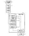
- FIG. 1 is a block diagram showing a configuration example of a video processing system according to Embodiment 1 of the present invention.
- the video processing system according to the first embodiment includes a video processing device 1, a depth enhancement processing device 2, a storage unit 3, and an output device 4.
- the depth emphasis processing device 2 acquires an image targeted for depth emphasis processing that improves a three-dimensional effect or a depth sensation, performs a process of emphasizing the three-dimensional effect / depth sensation of the acquired image, and applies the image subjected to the depth emphasis processing. This is given to the storage unit 3.
- the depth enhancement processing device 2 provides the storage unit 3 with video feature information indicating the characteristics of the video that has been subjected to the depth enhancement processing. Details of the video feature information will be described later.
- FIG. 2 is an explanatory diagram showing an example of a video for depth enhancement processing.
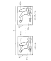
- the depth enhancement processing target video 5 is a moving image and includes a plurality of time-series frames 51 and 52.
- FIG. 2 conceptually shows a state in which the frames from the nth frame 51 to the n + mth frame 52 are expanded.
- Frames 51 and 52 are still images, which are data indicating the brightness and color of each of a plurality of pixels arranged two-dimensionally, and a plurality of objects having different distances in the depth direction, such as birds, trees, suns, It consists of video parts corresponding to subjects such as the sky and clouds.
- the frames 51 and 52 constituting the video 5 are composed of background video portions 51a and 52a having a long distance in the depth direction and moving body video portions 51b and 52b having a short distance in the depth direction.
- the distance in the depth direction refers to the distance between the subject related to the object and a predetermined position, for example, the position of the photographing apparatus used for capturing the video.
- the distance is referred to as depth as appropriate.
- Video 5 is encoded by an arbitrary compression method such as MPEG-2 (Moving Picture Expert Expert Group phase 2) or Motion-JPEG2000. Needless to say, the video 5 may be uncompressed.
- FIG. 3 is an explanatory diagram illustrating an example of a video on which depth enhancement processing has been performed.
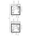
- the video 6 that has been subjected to the depth enhancement processing includes a plurality of time-series frames 61 and 62.
- FIG. 3 conceptually shows a state in which the respective frames from the nth frame 61 to which the depth emphasis processing has been performed to the n + mth frame 62 are developed, as in FIG. 2.
- Each of the frames 61 and 62 is a frame object surrounding the background video portions 61a and 62a, the peripheral video portions 61d and 62d arranged on part or all of the outer periphery of the background video portions 61a and 62a, and the background video portions 61a and 62a.
- the video 6 is generated by the following procedure, for example.
- the depth emphasis processing apparatus 2 acquires depth information indicating the depth of each of the plurality of objects constituting the frames 51 and 52 together with the video 5.
- the depth information includes information on the distance obtained by measuring the distance between the imaging device and each subject in the depth direction during imaging.
- the depth enhancement processing device 2 divides each frame 51, 52 of the acquired video 5 into a background video portion 51a, 52a and a moving body video portion 51b, 52b which is a foreground video portion based on the depth information. Then, as shown in FIG. 3, the depth emphasis processing apparatus 2 superimposes a frame object 62c for emphasizing the depth on a part of the background video portions 61a and 62a, and further, the background video portions 61a and 62a and the frame object. The bird's image part which is the moving body image parts 61b and 62b is superimposed on 62c.
- the depth emphasis processing apparatus 2 paints the outer regions of the frame objects 61c and 62c, that is, the peripheral video portions 61d and 62d with an arbitrary color. In this way, by describing the superposition relationship between each object, a part of the two-dimensionally drawn object is given an illusion as if it is popping out into the real world three-dimensional space. A stereoscopic effect or a sense of depth can be added to the video.
- the storage unit 3 includes, for example, a hard disk, an optical disk, a magneto-optical disk, a semiconductor memory, and the like, and stores the video 6 and video feature information given from the depth enhancement processing device 2 and other content videos.
- the storage unit 3 arranges layout layout information, which is video data of an arrangement layout 8 in which the video 6 and other content videos are arranged, and a layout for arranging a video formed by arranging the video 6 and other content videos. And the arrangement information regarding. Details of the arrangement information will be described later.
- the video feature information and arrangement information are stored in the storage unit 3 as structured data such as XML (eXtensible Markup Language), for example.
- the video processing device 1 acquires a video acquisition unit 11 that acquires a video 6 from the storage unit 3, a video feature acquisition unit 12 that acquires video feature information from the storage unit 3, and arrangement layout information and arrangement information from the storage unit 3.
- An arrangement information acquisition unit 13 that performs the arrangement
- an arrangement determination unit 14 that determines an arrangement area of the image 6 based on the image feature information and the arrangement information, and an image in which the image 6 and other content images are arranged according to the determined arrangement area.
- a video composition unit 15 for composition.
- the video acquisition unit 11 acquires the video 6 and other content videos stored in the storage unit 3, and gives the acquired video 6 and content videos to the video composition unit 15.
- the video acquisition unit 11 performs a process of combining the video 6 with the video 6 such as RGB format or YUV format.
- processing is performed on the combined video 6.
- the video acquired from the storage unit 3 is uniquely determined by a user instruction or the like.
- the video feature acquisition unit 12 acquires the video feature information stored in the storage unit 3 and provides the acquired video feature information to the arrangement determination unit 14.
- the video feature information includes frame shape information indicating the size of the frame objects 61c and 62c, and motion information indicating the moving range of the moving body video portions 61b and 62b.
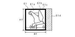
- FIG. 4 is an explanatory diagram conceptually showing frame shape information in one frame 61.
- the frame shape information is information including a width Wf and a height Hf of a rectangle circumscribing the frame object 61c.
- the width and height of the frame object 61c and the width Wf and height Hf of the rectangle circumscribing the frame object 61c are the same.
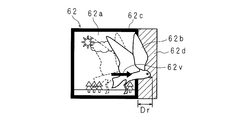
- FIG. 5 is an explanatory diagram conceptually showing the motion information in one frame 62.
- the motion information of the moving body video portion 62b includes the maximum jumping distance in the vertical and horizontal directions in which the moving body video portion 62b jumps over the frame object 62c from the background video portion 62a and jumps to the peripheral video portion 62d. It is information to include.
- a thick line arrow is a motion vector 62v indicating the motion of the moving object video portion 62b.
- the leftward maximum pop-out distance of the moving body video portion 62b is denoted as Dl
- the rightward maximum pop-out distance is Dr
- the upward maximum pop-out distance is Du
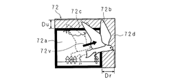
- the downward maximum pop-out distance is Db.
- FIG. 6 is an explanatory diagram conceptually showing frame shape information in another frame 71.
- the background video portion 71 a and the frame object 71 c are arranged on the lower left side
- the peripheral video portion 71 d is arranged on the right side portion and the upper side portion of the frame 71.
- the moving body video portion 71b protrudes upward.
- the video feature acquisition unit 12 acquires frame shape information including a width Wf and a height Hf of a rectangle circumscribing the frame object 71c arranged on the lower left side.
- FIG. 7 is an explanatory diagram conceptually showing motion information in other frames.
- a background video part 72a and a frame object 72c are arranged on the lower left side, and a peripheral video part 72d is arranged on the right side part and the upper part of the peripheral part.
- video part 72b has protruded to the upper right.
- a bold arrow is a motion vector 72v indicating the motion of the moving object video portion 72b.
- the arrangement information acquisition unit 13 acquires the arrangement layout information and the arrangement information stored in the storage unit 3 and gives the acquired arrangement information to the arrangement determination unit 14.
- FIG. 8A and 8B are explanatory diagrams conceptually showing arrangement layout information and arrangement information.
- FIG. 8A is an explanatory diagram conceptually showing the layout information
- FIG. 8B is an explanatory diagram conceptually showing specific contents of the layout information.
- the arrangement layout 8 represented by the arrangement layout information includes a plurality of arrangement areas 81, 82, 83, and 84 in which the video 6 and other content videos such as charts and characters are to be arranged. It is a picture including
- Each arrangement area 81, 82, 83, 84 is, for example, a substantially rectangular shape, and the arrangement area 81, 82, 83, 84 is arranged so that the video 6 and other content videos are fitted therein.
- FIG. 8A is an explanatory diagram conceptually showing the layout information
- FIG. 8B is an explanatory diagram conceptually showing specific contents of the layout information.
- the arrangement layout 8 represented by the arrangement layout information includes a plurality of arrangement areas 81, 82, 83, and 84 in which
- the arrangement information includes distances Lu, Lb, Ll, Lr from the upper side, lower side, left side, and right side of the arrangement areas 81, 82, 83, 84 to the outer periphery of the arrangement layout 8, and rectangular arrangement areas.
- 81, 82, 83, 84 includes information on the width Wt and height Ht of itself. 8B shows only the distances, widths, and heights related to the placement region 82, the same applies to the other placement regions 81, 83, and 84.
- the layout determination unit 14 Based on the video feature information and the layout information given from the video feature acquisition unit 12 and the layout information acquisition unit 13, the layout determination unit 14 arranges the layout areas 81, 82, and 83 in which the video 6 and other content videos should be placed. , 84, and the video composition unit 15 is provided with placement determination result information in which the video 6 and other content videos are associated with the placement areas 81, 82, 83, 84, and placement layout information.
- the arrangement determination unit 14 enlarges or reduces the image 6 and arranges the outer peripheral edges of the background image portions 61a and 62a and the frame objects 61c and 62c and the outer edge of the arrangement area 81, the moving body image portion 61b.
- the arrangement areas 81, 82, 83, 84 in which the moving body video portions 61 b and 62 b fit within the video of the arrangement layout 8 and the size of the background video portions 61 a and 62 a are maximized are arranged in the arrangement of the video 6. Determine as an area.
- the arrangement of the other content video is appropriately determined by the arrangement determining unit 14 based on the size of the content video. Details of the method for determining the arrangement area of the video 6 will be described later.
- the video composition unit 15 acquires the placement determination result information and the layout information given from the placement determination unit 14, and the video 6 and other content videos given from the video acquisition unit 11. Then, the video composition unit 15 enlarges or reduces the video 6 and other content videos based on the acquired arrangement determination result information, and arranges the enlarged or reduced video 6 and the content videos in the arrangement layout 8. Generate video. The video composition unit 15 gives the generated video to the output device 4.
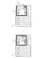
- FIG. 9 is an explanatory diagram conceptually showing an image obtained by arranging an image subjected to depth emphasis processing.
- the video 6 is arranged in the arrangement area 82.
- FIG. 9 shows a frame 62 constituting the video 6.
- the video 6 is enlarged or reduced so that the outer edge of the frame object 62c and the outer edge of the arrangement area 82 substantially coincide with each other, and the center point of the frame object 62c and the arrangement area so that the frame object 62c is fitted in the arrangement area 82.
- Video 6 is arranged at a position where the center points of 82 are matched.
- the video composition unit 15 does not appear in FIG. 9 because the peripheral video portion 62d is subjected to the transmission process.
- FIG. 10 is an explanatory diagram conceptually showing an image obtained by arranging a plurality of images. As shown in FIG. 10, other content videos 6a, 6b, 6c are arranged in the other arrangement areas 81, 83, 84.
- the output device 4 is, for example, a liquid crystal display, a plasma display, or an organic EL display, and displays an image given from the image composition unit 15.
- FIG. 11 is an explanatory diagram showing a first comparative example for explaining the effect of the video processing device 1 according to the first embodiment
- FIG. 12 shows the effect of the video processing device 1 according to the first embodiment.
- the frames 61 and 62 are enlarged or reduced so that the outer edge of the arrangement area 83 of the arrangement layout 8 and the outer edge of the frames 61 and 62 coincide with each other, and the enlarged or reduced frames 61 and 62 are arranged.
- An image arranged so as to fit in the region 83 is shown.
- the frames 61 and 62 are enlarged or reduced so that the outer edge of the arrangement area 83 of the arrangement layout 8 and the outer edge of the frame objects 61c and 62c coincide with each other.
- video which arrange
- the large video 6 is generated without generating a useless video space 85. Can be arranged so as not to impair the effect of the depth emphasis processing.
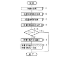
- FIG. 13 is a flowchart showing the procedure of the video processing method according to the first embodiment.
- the video acquisition unit 11 acquires the video 6 and other content video stored in the storage unit 3, and provides the acquired video 6 and content video to the video composition unit 15 (step S11).
- the video feature acquisition unit 12 acquires the video feature information stored in the storage unit 3, gives the acquired video feature information to the arrangement determination unit 14 (step S12), and the arrangement information acquisition unit 13 stores the storage unit. 3 acquires the layout layout information and the layout information stored therein, and gives the acquired layout layout information and layout information to the layout determination unit 14 (step S13).
- the arrangement determination unit 14 arranges the video 6 and other content videos to be arranged based on the video feature information given from the video feature acquisition unit 12 and the arrangement information acquisition unit 13 and the arrangement layout information and arrangement information.
- the areas 81, 82, 83, and 84 are determined, and the layout determination result information and the layout layout information are given to the video composition unit 15 (step S14).
- the arrangement areas 81, 82, 83, and 84 that are uniquely determined as areas in which the video 6 and other content videos are to be arranged are referred to as video arrangement areas.
- FIG. 14 is a flowchart showing a processing procedure related to determination of a video arrangement area.
- the arrangement determination unit 14 starts the process related to the video arrangement area, first, based on the arrangement information, whether or not the arrangement of the video 6 has been inspected for all the arrangement areas 81, 82, 83, and 84 is checked. Determination is made (step S31).
- step S31 When it is determined that all the placement areas 81, 82, 83, and 84 have not been examined for appropriateness of the placement of the video 6 (step S31: NO), the placement determination unit 14 has not yet been examined. , 82, 83, 84 are inspected for suitability (step S32).
- the placement determination unit 14 that has started the processing for checking the suitability of the placement area sets the placement areas 81, 82, 83, and 84 that satisfy all of the following expressions (1) to (4) as placement area candidates for the video 6.
- ⁇ * Dl ⁇ Ll (1) ⁇ * Dr ⁇ Lr (2) ⁇ * Du ⁇ Lu (3) ⁇ * Db ⁇ Lb (4)
- ⁇ Wt / Wf (5)
- ⁇ Ht / Hf (6)
- the maximum protruding distances in the left direction, the right direction, the upward direction, and the downward direction in the enlarged or reduced image 6 do not reach the outside of the layout layout 8. That is, the moving body video portions 61 b and 62 b do not protrude from the arrangement layout 8.
- the enlargement ratio or reduction ratio is determined so that the background image portions 61a and 62a match the width and height of the arrangement area to be inspected. Needless to say, ⁇ and ⁇ may be set.
- FIG. 15 is a flowchart showing a processing procedure related to the placement area suitability inspection.
- the arrangement determining unit 14 calculates the horizontal enlargement or reduction ratio ⁇ of the video 6 using the above formula (5) (step S51), and then uses the above formula (6) to calculate the video 6
- the enlargement or reduction ratio ⁇ in the vertical direction is calculated (step S52).
- the arrangement determining unit 14 determines whether ⁇ ⁇ D1 is equal to or less than the distance L1 (step S53). That is, it is determined whether or not the pop-up distance ⁇ ⁇ D1 of the moving body video portions 61b and 62b after the enlargement or reduction is equal to or less than the distance L1 from the left side of the arrangement areas 81, 82, 83, and 84 to the left side of the arrangement layout 8. judge.
- step S53 determines whether ⁇ ⁇ Dr is equal to or less than the distance Lr (step S54). That is, it is determined whether the pop-up distance ⁇ ⁇ Dr of the enlarged and reduced moving body video portions 61b and 62b is equal to or less than the distance Lr from the right side of the placement areas 81, 82, 83, and 84 to the right side of the placement layout 8. judge.
- step S54 determines whether ⁇ ⁇ Du is equal to or less than the distance Lu (step S55). That is, it is determined whether the pop-up distance ⁇ ⁇ Du of the enlarged or reduced moving body video portions 61b and 62b is equal to or less than the distance Lu from the upper side of the arrangement areas 81, 82, 83, and 84 to the upper side of the arrangement layout 8. judge.
- the arrangement determining unit 14 determines whether ⁇ ⁇ Db is equal to or less than the distance Lb (step S56). That is, it is determined whether the pop-up distance ⁇ ⁇ Db of the enlarged and reduced moving body video portions 61b and 62b is equal to or less than the distance Lb from the lower side of the arrangement areas 81, 82, 83, and 84 to the lower side of the arrangement layout 8. .
- step S56 When it is determined that ⁇ ⁇ Db is equal to or less than the distance Lb (step S56: YES), the arrangement determining unit 14 sets the arrangement areas 81, 82, 83, and 84 to be inspected as arrangement area candidates (step S57), and performs processing. Finish.
- step S53 When it is determined that ⁇ ⁇ D1 is greater than the distance L1 (step S53: NO), when it is determined that ⁇ ⁇ Dr is greater than the distance Lr (step S54: NO), when it is determined that ⁇ ⁇ Du is greater than the distance Lu (Step S55: NO), when it is determined that ⁇ ⁇ Db is greater than the distance Lb (Step S56: NO), the placement determination unit 14 sets the placement regions 81, 82, 83, and 84 to be inspected as non-placement region candidates. If there is (step S58), the process is terminated.
- the arrangement determination unit 14 that has finished the processing related to the suitability inspection of the placement area, based on the return value of the suitability check, the placement areas 81, 82, 83, 84 to be examined are placement area candidates. Is determined (step S33). When it determines with it not being an arrangement
- step S31 If it is determined in step S31 that all arrangement areas have been inspected (step S31: YES), the arrangement determination unit 14 determines whether there is at least one arrangement area candidate (step S35). If it is determined that there are no placement area candidates (step S35: NO), the placement determination unit 14 stores that there is an error regarding the placement of the video (step S39), and ends the process. When it is determined that there is at least one placement area candidate (step S35: YES), the placement determination unit 14 determines whether there are a plurality of placement area candidates (step S36).
- step S36 If it is determined that there are a plurality of placement area candidates (step S36: YES), the video 6 is narrowed down to one placement area to be placed (step S37).
- Maxim ⁇ ⁇ ⁇ is maximized, that is, the arrangement areas 81, 82, 83, and 84 in which the video 6 is displayed the largest are shown.
- Min
- step S37 When the process of step S37 is completed, or when it is determined in step S36 that there is a single arrangement area candidate (step S36: NO), the arrangement determination unit 14 selects one arrangement area 81, 82, 83, 84 is determined (step S38), and the process ends.
- the arrangement determination unit 14 determines whether or not there is an error regarding the arrangement of the video 6 (step S ⁇ b> 15). If it is determined that there is an error (step S15: YES), the arrangement determining unit 14 ends the process. When it is determined that there is no error (step S15: NO), the video composition unit 15 enlarges or reduces the video 6 using the enlargement or reduction ratios ⁇ and ⁇ (step S16). Then, the video composition unit 15 generates a video in which the enlarged or reduced video 6 and other content videos are arranged on the layout layout 8 (step S17), and the process ends.
- the video processing system configured as described above, it is possible to arrange the video that has been subjected to the process of enhancing the depth feeling so that the effect of the depth feeling enhancement process is not impaired. .
- FIG. 16 is a block diagram illustrating a configuration example of a video processing system according to a modification.
- the video processing system according to the modification includes a depth enhancement processing device 2, a video processing device 101, a storage unit 3, and an output device 4 similar to those in the first embodiment, and the video processing device 101 stores video feature information.
- the difference is that the video feature information is calculated based on the video instead of being acquired from the video. Below, the said difference is mainly demonstrated.
- the video processing apparatus 101 includes a video acquisition unit 111, a video feature calculation unit 112, an arrangement information acquisition unit 13, an arrangement determination unit 14, and a video composition unit 15.
- the configuration other than the video feature calculation unit 112 is the same as that of the first embodiment.
- the video feature calculation unit 112 acquires the video 6 stored in the storage unit 3, calculates video feature information based on the acquired video 6, and provides the calculated video feature information to the arrangement determination unit 14.
- the video feature calculation unit 112 recognizes the frame objects 61c and 62c included in the video 6 by pattern recognition such as texture analysis and pattern matching, and the short side and the long side of the rectangle circumscribing the frame objects 61c and 62c.
- the length, that is, the frame shape information is calculated. More specifically, the video feature calculation unit 112 having a texture analysis function extracts a video area having substantially the same video pattern from the video 6, and sets the video areas common to the frames 61 and 62 as frame objects 61c and 62c.
- the video feature calculation unit 112 having a pattern matching function stores the template video of the frame objects 61c and 62c, calculates the degree of coincidence between the video 6 and the template video, for example, the Euclidean distance, and the correlation. What is necessary is just to comprise so that a high image
- the video feature calculation unit can recognize the non-peripheral video portion protruding outside the frame objects 61c and 62c as the moving body video portions 61b and 62b, and calculate motion information.
- FIG. 17 is a block diagram illustrating a configuration example of the video processing system according to the second embodiment.
- the video processing system according to the second embodiment includes the same video processing device 201, depth enhancement processing device 2, storage unit 3, and output device 4 as in the first embodiment.
- the arrangement area where the videos 206 and 207 are arranged in the arrangement layout 208 is determined in advance, and the storage unit 3 stores the videos 206 and 207 suitable for the specific arrangement area.
- the difference is that a plurality of images 206 and 207 are selected. Below, the said difference is mainly demonstrated.
- the video processing apparatus 201 includes a video selection unit 212, an arrangement information acquisition unit 213, an arrangement determination unit 214, and a video composition unit 15. Configurations other than the arrangement information acquisition unit 213 and the video selection unit 212 are the same as those in the first embodiment.
- the arrangement information acquisition unit 213 acquires the arrangement layout information and arrangement information stored in the storage unit 3, gives the acquired arrangement information to the video selection unit 212, and uses the acquired arrangement layout information and arrangement information as the arrangement determination unit 214.
- FIG. 18A and 18B are explanatory diagrams conceptually showing the layout layout 208 and the layout information according to the second embodiment.
- FIG. 18A is an explanatory diagram conceptually showing the layout information
- FIG. 18B is an explanatory diagram conceptually showing specific contents of the layout information.
- the arrangement layout 208 represented by the arrangement layout information is basically the same as the arrangement layout in the first embodiment. However, the arrangement area in which the images 206 and 207 that have been subjected to the depth emphasis processing are to be arranged is determined in advance.
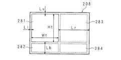
- an arrangement area 281 surrounded by a solid line indicates an area where the images 206 and 207 that have been subjected to the depth emphasis process are to be arranged.
- the arrangement information includes the distances Lu, Lb, Ll, Lr from the upper side, lower side, left side, and right side of the arrangement areas 281, 282, 283, 284 to the outer periphery of the arrangement layout 208, and rectangular arrangement areas. It includes information on the width Wt and height Ht of 281, 282, 283, 284 itself.
- FIG. 18B shows only the distances, widths, and heights related to the arrangement area 281, but the same applies to the other arrangement areas 282, 283, and 284.
- the arrangement information includes information for specifying an arrangement area in which the images 206 and 207 that have been subjected to the depth emphasis process are to be arranged.
- the video selection unit 212 includes a video feature acquisition unit 212a that acquires video feature information of each of a plurality of videos stored in the storage unit 3, a video feature information acquired by the video feature acquisition unit 212a, and an arrangement information acquisition unit.
- a video acquisition unit 212b that selects one video 206, 207 based on the arrangement information given from 213 and acquires the selected video 206, 207 and another content video.
- the video acquisition unit 212 b gives the selected videos 206 and 207 and other content videos to the video synthesis unit 15.
- 19A and 19B are explanatory diagrams conceptually showing frame shape information and motion information in a plurality of videos 206 and 207 stored in the storage unit 3.
- 19A is an explanatory diagram showing frame shape information and motion information of the first video 206
- FIG. 19B is an explanatory diagram showing frame shape information and motion information of the second video 207.
- the frame shape information is information including a width Wf and a height Hf of a rectangle circumscribing the frame objects 261c and 271c, as in the first embodiment.
- the movement information of the moving body video portions 261b and 271b is obtained in the vertical and horizontal directions in which the moving body video portions 261b and 271b jump over the frame objects 261c and 271c from the background video portions 261a and 271a to the peripheral video portions 261d and 271d.
- This information includes the maximum pop-up distance. If the images 206 and 207 are different, the frame shape information and the motion information are basically different. In FIG. 19, bold arrows are motion vectors 261v and 271v indicating the motion of the moving body video portions 261b and 271b.
- FIG. 20 is a flowchart showing the procedure of the video processing method according to the second embodiment.
- the arrangement information acquisition unit 213 acquires the arrangement layout information and arrangement information stored in the storage unit 3, gives the acquired arrangement information to the video selection unit 212, and decides the arrangement of the acquired arrangement layout information and arrangement information.
- the video selection unit 212 identifies the arrangement area 281 in which the videos 206 and 207 that have been subjected to the depth enhancement processing are to be arranged based on the arrangement information given from the arrangement information acquisition unit 213 (step S212).
- the arrangement information includes distances L1, Lt, Lr, and Lb from the left end, upper end, right end, and lower end of each arrangement area 281, 282, 283, and 284, and the width Wt and height of the arrangement areas 281, 282, 283, and 284.
- Ht and identification information for identifying the arrangement area 281 in which the images 206 and 207 that have been subjected to the depth enhancement processing are to be arranged are included.
- the video selection unit 212 specifies the arrangement area 281 in which the videos 206 and 207 should be arranged using the specifying information included in the arrangement information.
- the video selection unit 212 selects one video 206, 207 to be arranged in the arrangement area 281 from the plurality of videos 206, 207 stored in the storage unit 3, and selects the selected one video 206. , 207 and other content videos are obtained from the storage unit 3, and the obtained one video 206, 207 and other content videos are provided to the video composition unit 15 (step S213).
- FIG. 21 is a flowchart showing a processing procedure related to selection of an arrangement video.
- the video selection unit 212 starts the process related to the selection of the arrangement video, first, the video selection unit 212 determines whether all the videos 206 and 207 stored in the storage unit 3 have been checked for appropriateness of arrangement (step S231). ).
- step S231 When it is determined that the placement suitability of all the videos 206 and 207 has not been checked (step S231: NO), the video selection unit 212 acquires one video 206 and 207 that has not been checked yet from the storage unit 3. (Step S232), image feature information corresponding to the acquired images 206 and 207 is acquired (step S233).
- the example in which the images 206 and 207 are acquired together with the image feature information has been described. However, the image 206 and 207 may not be acquired, and only the image feature information may be acquired.
- the video selection unit 212 checks the suitability of the videos 206 and 207 to be placed in the placement area 281 (step S234). As in the first embodiment, the video selection unit 212 checks whether the videos 206 and 207 satisfying all of the above formulas (1) to (4) are appropriate videos to be placed in the placement area 208. .
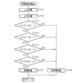
- FIG. 22 is a flowchart showing a processing procedure related to the video suitability inspection in the second embodiment.
- the video selection unit 212 performs the same processing as that in steps S51 to S56 in the first embodiment on the relationship between the one video 206 and 207 acquired in step S232 and the arrangement area 281 specified in step S212. This is executed in step S256. If it is determined in step S256 that ⁇ ⁇ Db is equal to or less than the distance Lb (step S256: YES), the placement determination unit 214 places one image 206 or 207 to be inspected in the placement region 281. The candidate video is determined (step S257), and the process is terminated.
- Step S253 When it is determined that ⁇ ⁇ D1 is greater than the distance L1 (step S253: NO), when it is determined that ⁇ ⁇ Dr is greater than the distance Lr (step S254: NO), when it is determined that ⁇ ⁇ Du is greater than the distance Lu (Step S255: NO), when it is determined that ⁇ ⁇ Db is larger than the distance Lb (Step S256: NO), the video selection unit 212 assumes that the videos 260 and 207 to be inspected are non-candidate videos ( Step S258), the process ends.
- the video selection unit 212 that has finished the process related to the suitability check of the arrangement video determines whether the videos 206 and 207 to be inspected are candidate videos based on the return value of the suitability check. (Step S235). When it determines with it not being a candidate image
- step S231 determines whether there is no image candidate to be arranged in the arrangement area 281 (step S231). S237). If it is determined that there is no candidate video (step S237: NO), the video selection unit 212 stores that there is an error regarding the video arrangement (step S241), and ends the process. If it is determined that there is at least one candidate video (step S237: YES), the video selection unit 212 determines whether there are a plurality of candidate videos (step S238).
- the videos 206 and 207 are narrowed down to one (step S239).
- the narrowed videos 206 and 207 are determined as videos to be placed in the placement area 281 (step S240), and the process ends.
- it may be configured to receive a separate user instruction and select one video 206, 207 from a plurality of candidate videos.
- the arrangement determination unit 214 determines whether or not there is an error regarding the arrangement of the videos 206 and 207 (step S214). If it is determined that there is an error (step S214: YES), the arrangement determining unit 214 ends the process. When it is determined that there is no error (step S214: NO), the video composition unit 15 enlarges or reduces the videos 206 and 207 using the enlargement or reduction ratios ⁇ and ⁇ (step S215). Then, the video composition unit 15 generates a video in which the enlarged or reduced videos 206 and 207 and other content videos are arranged on the layout layout 208 (step S216), and the process ends.
- the video processing system according to the second embodiment configured as described above has the same effects as those of the first embodiment.
- FIG. 23 is a block diagram illustrating a configuration example of the video processing system according to the third embodiment.
- the video processing apparatus 301 according to the third embodiment is realized by causing the computer 301 to execute the computer program 309a according to the present invention.
- the computer 301 includes a CPU (Central Processing Unit) 311 that controls the entire apparatus.
- the CPU 311 includes a ROM (Read Only Memory) 312, a RAM (Random Access Memory) 313 that stores temporary information generated in accordance with the calculation, and a recording medium that records the computer program 309 a according to the embodiment of the present invention.
- 309 for example, an external storage device 314 that reads a computer program 309a from a CD-ROM, an internal storage device 315 such as a hard disk that records the computer program 309a read by the external storage device 314, an input unit 316, and an output unit 317 It is connected.
- the CPU 311 implements the video processing method according to the present invention by reading the computer program 309a from the internal storage device 315 into the RAM 313 and executing various arithmetic processes.
- the processing procedure of the CPU 311 is as shown in FIGS. 13 and 15, and the processing procedure of steps S11 to 17, steps S31 to 39, and steps S51 to 58 is executed. Since the processing procedure is the same as the processing contents of the components constituting the video processing devices 1 and 101 according to the first embodiment and the modification, detailed description thereof will be omitted.
- the computer 301 is caused to function as the video processing device 1 according to the first embodiment, and the video processing method according to the first embodiment is performed.
- the same effects as those of the first embodiment and the modification can be obtained.
- the CPU may be configured to execute the processing procedures of steps S211 to 216, steps S231 to 241 and steps S251 to 258 as shown in FIGS. Since the processing procedure is the same as the processing contents of each component constituting the video processing apparatus 201 according to the second embodiment, detailed description thereof will be omitted.
- the computer and the computer program configured as described above the computer can function as the video processing apparatus 201 according to the second embodiment, and the video processing method according to the second embodiment can be performed. The same effects as those of the second embodiment are obtained.
- the computer program 309a according to the third embodiment is not limited to the one recorded in the recording medium 309, and is downloaded, stored, and executed via a wired or wireless communication network. There may be.
Landscapes
- Physics & Mathematics (AREA)
- General Physics & Mathematics (AREA)
- Engineering & Computer Science (AREA)
- Theoretical Computer Science (AREA)
- Controls And Circuits For Display Device (AREA)
- Processing Or Creating Images (AREA)
- Transforming Electric Information Into Light Information (AREA)
Abstract
奥行き感を強調させる映像処理が施された映像を、奥行き感強調処理の効果が損なわれないように配列させることができる映像処理装置を提供する。 複数の映像を配列させる映像処理装置に、背景映像部分、該背景映像部分の周縁の一部又は全部に配された周縁映像部分、及び前記背景映像の内側から該周縁映像部分へ飛び出す移動体映像部分を含む一つの映像を取得する映像取得部11と、背景映像部分の大きさ及び移動体映像部分の移動範囲を示した情報を取得する映像特徴取得部12と、映像特徴取得部12にて取得した情報が示す大きさ及び移動範囲に基づいて、前記一つの映像の配置領域を決定する配置決定部14と、配置決定部14の決定結果に基づいて、前記一つの映像及び他の映像を配列させる映像合成部15とを備える。
Description
本発明は、複数の映像を配列させる映像処理装置、映像処理方法及びコンピュータプログラムに関する。
昨今、デジタルカメラ、デジタルカメラ機能を搭載した携帯電話の普及により、映像を撮影し、撮影された映像をデジタルデータとして保存することが一般的になってきている。また、ネットワーク環境の発達、及び高性能なパーソナルコンピュータ(PC:Personal Computer)の普及によって、ユーザ自身がコンテンツを作成し、他のユーザに公開することが一般的に行われている。ユーザによって作成されたコンテンツは、UGC(User Generated Contents)と呼ばれる。UGCの例としては、静止画、動画などの映像を組み合わせて作成されたフォトアルバム、映像に文字を組み合わせることで作成されたブログに代表される日記形式のコンテンツ等が挙げられる。
一方、特許文献1には、入力された映像に応じたレイアウトパターンを自動生成し、該映像を所定の大きさに拡大縮小させる自動レイアウト機能を有するレイアウト装置が開示されている。
しかしながら、デザイナー等のプロの知識を持ち合わせないユーザにとっては、奥行き感を強調させるなどの特殊な処理が施された映像の効果的なレイアウトを適切に行うことは困難であるという問題があった。
特許文献1に開示されたレイアウト装置によれば、入力された映像に応じたレイアウトパターンを作成することができるが、映像処理の効果を考慮した映像の配列は行われていない。従って、映像の配列方法によっては、該映像に施された映像処理の効果が損なわれることがあった。
特許文献1に開示されたレイアウト装置によれば、入力された映像に応じたレイアウトパターンを作成することができるが、映像処理の効果を考慮した映像の配列は行われていない。従って、映像の配列方法によっては、該映像に施された映像処理の効果が損なわれることがあった。
本発明は斯かる事情に鑑みてなされたものであり、奥行き感を強調させる映像処理が施された映像を、奥行き感強調処理の効果が損なわれないように配列させることができる映像処理装置、映像処理方法及びコンピュータプログラムを提供することを目的とする。
本発明に係る映像処理装置は、複数の映像を配列させる映像処理装置において、背景映像部分、及び前記背景映像部分から該背景映像部分の外側へ飛び出す移動体映像部分を含む一つの映像を取得する映像取得手段と、背景映像部分の大きさ及び移動体映像部分の移動範囲を示した情報を取得する映像特徴取得手段と、該映像特徴取得手段にて取得した情報が示す大きさ及び移動範囲に基づいて、前記一つの映像の配置領域を決定する配置決定手段と、該配置決定手段の決定結果に基づいて、前記一つの映像及び他の映像を配列させる手段とを備えることを特徴とする。
本発明に係る映像処理方法は、複数の映像を配列させる映像処理方法において、背景映像部分、及び前記背景映像部分から該背景映像部分の外側へ飛び出す移動体映像部分を含む一つの映像を取得するステップと、背景映像部分の大きさ及び移動体映像部分の移動範囲を示した情報を取得するステップと、取得した情報が示す大きさ及び移動範囲に基づいて、前記一つの映像の配置領域を決定するステップと、取得した前記一つの映像及び他の映像を、配置領域の決定結果に基づいて、配列させるステップとを備えることを特徴とする。
本発明に係るコンピュータプログラムは、コンピュータに、複数の映像を配列してなる映像を生成させるコンピュータプログラムにおいて、コンピュータを、背景映像部分、及び前記背景映像部分から該背景映像部分の外側へ飛び出す移動体映像部分を含む一つの映像を取得する映像取得手段と、背景映像部分の大きさ及び移動体映像部分の移動範囲を示した情報を取得する映像特徴取得手段と、該映像特徴取得手段にて取得した情報が示す大きさ及び移動範囲に基づいて、前記一つの映像の配置領域を決定する配置決定手段と、該配置決定手段の決定結果に基づいて、前記一つの映像及び他の映像を配列してなる映像を生成させる手段として機能させることを特徴とする。
本発明にあっては、背景映像部分、及び前記背景映像部分から該背景映像部分の外側へ飛び出す移動体映像部分を含む一つの映像と、他の映像を配列する際、一つの映像に含まれる背景映像部分の大きさと、該背景映像部分から飛び出す移動体映像部分の移動範囲を考慮して、前記一つの映像を配置する。
本発明に係る映像処理装置は、複数の映像を配列させる映像処理装置において、背景映像部分、及び前記背景映像部分から該背景映像部分の外側へ飛び出す移動体映像部分を含む一つの映像を取得する映像取得手段と、該映像取得手段にて取得した映像に基づいて、該映像に含まれる背景映像部分の大きさ及び移動体映像部分の移動範囲を算出する映像特徴算出手段と、該映像特徴算出手段にて算出した大きさ及び移動範囲に基づいて、前記一つの映像の配置領域を決定する配置決定手段と、該配置決定手段の決定結果に基づいて、前記一つの映像及び他の映像を配列させる手段とを備えることを特徴とする。
本発明に係る映像処理方法は、複数の映像を配列させる映像処理方法において、背景映像部分、及び前記背景映像部分から該背景映像部分の外側へ飛び出す移動体映像部分を含む一つの映像を取得するステップと、取得した映像に基づいて、該映像に含まれる背景映像部分の大きさ及び移動体映像部分の移動範囲を算出するステップと、算出した大きさ及び移動範囲に基づいて、前記一つの映像の配置領域を決定するステップと、取得した前記一つの映像及び他の映像を、配置領域の決定結果に基づいて、配列させるステップとを備えることを特徴とする。
本発明に係るコンピュータプログラムは、コンピュータに、複数の映像を配列してなる映像を生成させるコンピュータプログラムにおいて、コンピュータを、背景映像部分、及び前記背景映像部分から該背景映像部分の外側へ飛び出す移動体映像部分を含む一つの映像を取得する映像取得手段と、該映像取得手段にて取得した映像に基づいて、該映像に含まれる背景映像部分の大きさ及び移動体映像部分の移動範囲を算出する映像特徴算出手段と、該映像特徴算出手段にて算出した大きさ及び移動範囲に基づいて、前記一つの映像の配置領域を決定する配置決定手段と、該配置決定手段の決定結果に基づいて、前記一つの映像及び他の映像を配列してなる映像を生成させる手段として機能させることを特徴とする。
本発明にあっては、背景映像部分、及び前記背景映像部分から該背景映像部分の外側へ飛び出す移動体映像部分を含む一つの映像と、他の映像を配列する際、該一つの映像に基づいて、該背景映像部分の大きさと、移動体映像部分の移動範囲とを算出する。そして、背景映像部分の大きさと、該背景映像部分から飛び出す移動体映像部分の移動範囲を考慮して、前記一つの映像を配置する。
本発明に係る映像処理装置は、前記配置決定手段は、移動体映像部分が、複数の映像を配列してなる映像の内側に収まるように、前記一つの映像の配置領域を決定するようにしてあることを特徴とする。
本発明にあっては、複数の映像を配列して得られる映像の周縁部から、移動体映像部分がはみ出すことは無い。
本発明に係る映像処理装置は、複数の映像が配されるべき複数の配置領域を示した配置情報を取得する配置情報取得手段を備え、前記配置決定手段は、前記配置情報取得手段にて取得した配置情報が示す複数の配置領域の中から、特定の配置領域を決定するようにしてあることを特徴とする。
本発明にあっては、複数の映像が配されるべき複数の配置領域を示した配置情報を取得し、該複数の配置領域の中から、前記一つの映像が配される特定の配置領域を選択する。
本発明に係る映像処理装置は、前記一つの映像の大きさを、背景映像部分が配置領域に収まるように変更する手段を備え、前記配置決定手段は、背景映像部分の大きさが最大になる配置領域を決定するようにしてあることを特徴とする。
本発明にあっては、前記一つの映像の大きさが最大になるように、該一つの映像の配置領域を決定する。
本発明に係る映像処理装置は、背景映像部分及び移動体映像部分を含む一つの映像、並びに背景映像部分の大きさ及び移動体映像部分の移動範囲を示した情報を記憶した記憶手段を備えることを特徴とする。
本発明にあっては、背景映像部分、周縁映像部分及び移動体映像部分を含む映像と、背景映像部分の大きさ及び移動体映像部分の移動範囲を示した情報を記憶手段が記憶している。
本発明に係る映像処理装置は、複数の映像を配列させる映像処理装置において、複数の映像が配されるべき配置領域を示した配置情報を取得する配置情報取得手段と、背景映像部分、及び前記背景映像部分から該背景映像部分の外側へ飛び出す移動体映像部分を含む映像、並びに背景映像部分の大きさ及び移動体映像部分の移動範囲を示した情報を記憶した記憶手段と、該記憶手段が記憶している情報が示す大きさ及び移動範囲に基づいて、前記配置情報取得手段にて取得した配置情報が示した配置領域に配することが可能な一つの映像を前記記憶手段から取得する映像取得手段と、前記一つの映像及び他の映像を配列させる手段とを備えることを特徴とする。
本発明に係る映像処理方法は、背景映像部分、及び前記背景映像部分から該背景映像部分の外側へ飛び出す移動体映像部分を含む映像、並びに背景映像部分の大きさ及び移動体映像部分の移動範囲を示した情報を記憶した記憶手段を用いて、複数の映像を配列させる映像処理方法において、複数の映像が配されるべき配置領域を示した配置情報を取得するステップと、取得した配置情報が示した配置領域に配することが可能な一つの映像を、前記記憶手段が記憶している情報が示す大きさ及び移動範囲に基づいて、前記記憶手段から取得するステップと、取得した前記一つの映像及び他の映像を配列させるステップとを備えることを特徴とする。
本発明に係るコンピュータプログラムは、背景映像部分、及び前記背景映像部分から該背景映像部分の外側へ飛び出す移動体映像部分を含む映像、並びに背景映像部分の大きさ及び移動体映像部分の移動範囲を示した情報を記憶した記憶手段を備えたコンピュータに、複数の映像を配列してなる映像を生成させるコンピュータプログラムにおいて、コンピュータを、複数の映像が配されるべき配置領域を示した配置情報を取得する配置情報取得手段と、前記記憶手段が記憶している情報が示す大きさ及び移動範囲に基づいて、前記配置情報取得手段にて取得した配置情報が示した配置領域に配することが可能な一つの映像を前記記憶手段から取得する映像取得手段と、前記一つの映像及び他の映像を配列してなる映像を生成させる手段として機能させることを備えることを特徴とする。
本発明にあっては、背景映像部分、及び前記背景映像部分から該背景映像部分の外側へ飛び出す移動体映像部分を含む映像が複数ある。複数の映像を配列させる際、背景映像部分の大きさと、該背景映像部分から飛び出す移動体映像部分の移動範囲を考慮して、複数ある映像の中から一つの映像を選択し、配置する。
本発明によれば、奥行き感を強調させる映像処理が施された映像を、奥行き感強調処理の効果が損なわれないように配列させることができる。
以下、本発明の実施の形態を図面に基づいて詳述する。
(実施の形態1)
図1は、本発明の実施の形態1に係る映像処理システムの一構成例を示すブロック図である。本実施形態1に係る映像処理システムは、映像処理装置1、奥行き強調処理装置2、記憶部3及び出力装置4を有する。
(実施の形態1)
図1は、本発明の実施の形態1に係る映像処理システムの一構成例を示すブロック図である。本実施形態1に係る映像処理システムは、映像処理装置1、奥行き強調処理装置2、記憶部3及び出力装置4を有する。
奥行き強調処理装置2は、立体感又は奥行き感を向上させる奥行き強調処理対象の映像を取得し、取得した映像の立体感・奥行き感を強調させる処理を行い、奥行き強調処理が施された映像を記憶部3に与える。また、奥行き強調処理装置2は、奥行き強調処理が施された映像の特徴を示した映像特徴情報を記憶部3に与える。映像特徴情報の詳細は後述する。
図2は、奥行き強調処理対象の映像の一例を示す説明図である。奥行き強調処理対象の映像5は、動画であり、時系列の複数のフレーム51,52を含む。図2には、第nのフレーム51から第n+mのフレーム52までの各フレームを展開した様子を概念的に示している。フレーム51,52は、静止映像であって、二次元に配列された複数の画素夫々の輝度及び色を示したデータであり、奥行き方向の距離が異なる複数のオブジェクト、例えば鳥、木、太陽、空、雲等の被写体に相当する映像部分から構成されている。ここでは、映像5を構成するフレーム51,52は、奥行き方向の距離が長い背景映像部分51a,52aと、奥行き方向の距離が短い移動体映像部分51b,52bとで構成されているとする。奥行き方向の距離とは、オブジェクトに係る被写体と、所定位置、例えば該映像の撮像に用いた撮影装置の位置との距離をいう。以下、該距離を適宜、奥行きという。映像5は、所定の符号化方式、例えばMPEG-2(Moving Picture Expert Group phase2)、若しくはMotion-JPEG2000などの任意の圧縮方式で符号化されている。なお、言うまでもなく、映像5は、非圧縮であっても良い。
図3は、奥行き強調処理が施された映像の一例を示す説明図である。奥行き強調処理が施された映像6は、時系列の複数のフレーム61,62を含む。図3には、図2と同様、奥行き強調処理が施された第nのフレーム61から第n+mのフレーム62までの各フレームを展開した様子を概念的に示している。各フレーム61,62は、背景映像部分61a,62a、背景映像部分61a,62aの周縁の外側の一部又は全部に配された周縁映像部分61d,62d、背景映像部分61a、62aを囲む枠オブジェクト61c,62c、及び背景映像部分61a,62aから枠オブジェクト61c,62cを乗り越えて周縁映像部分61d,62dへ飛び出す移動体映像部分61b,62bを含む。映像6は、例えば、以下の手順で生成される。
奥行き強調処理装置2は、映像5と共に、フレーム51,52を構成する複数のオブジェクト夫々の奥行きを示した奥行き情報を取得する。本実施の形態では、奥行き方向における撮影装置及び各被写体間の距離を撮像時に計測しておき、計測して得られた距離の情報を有する奥行き情報である。奥行き強調処理装置2は、取得した映像5の各フレーム51,52を、奥行き情報に基づいて、背景映像部分51a,52aと、前景映像部分である移動体映像部分51b,52bとに分割する。そして、奥行き強調処理装置2は、図3に示すように、背景映像部分61a,62aの一部に、奥行きを強調するための枠オブジェクト62cを重畳させ、更に背景映像部分61a,62a及び枠オブジェクト62cの上に移動体映像部分61b,62bである鳥の映像部分を重畳する。次いで、奥行き強調処理装置2は、枠オブジェクト61c,62cの外側の領域、即ち周縁映像部分61d,62dを任意の色で塗りつぶす。このようにして、各オブジェクト間の重畳関係を描写することによって、二次元的に描写されたオブジェクトの一部が恰も現実世界の三次元空間に飛び出しているように錯覚を起こさせ、二次元の映像に立体感又は奥行き感を付与することができる。
奥行き強調処理装置2は、映像5と共に、フレーム51,52を構成する複数のオブジェクト夫々の奥行きを示した奥行き情報を取得する。本実施の形態では、奥行き方向における撮影装置及び各被写体間の距離を撮像時に計測しておき、計測して得られた距離の情報を有する奥行き情報である。奥行き強調処理装置2は、取得した映像5の各フレーム51,52を、奥行き情報に基づいて、背景映像部分51a,52aと、前景映像部分である移動体映像部分51b,52bとに分割する。そして、奥行き強調処理装置2は、図3に示すように、背景映像部分61a,62aの一部に、奥行きを強調するための枠オブジェクト62cを重畳させ、更に背景映像部分61a,62a及び枠オブジェクト62cの上に移動体映像部分61b,62bである鳥の映像部分を重畳する。次いで、奥行き強調処理装置2は、枠オブジェクト61c,62cの外側の領域、即ち周縁映像部分61d,62dを任意の色で塗りつぶす。このようにして、各オブジェクト間の重畳関係を描写することによって、二次元的に描写されたオブジェクトの一部が恰も現実世界の三次元空間に飛び出しているように錯覚を起こさせ、二次元の映像に立体感又は奥行き感を付与することができる。
記憶部3は、例えば、ハードディスク、光ディスク、光磁気ディスク、半導体メモリなどで構成されており、奥行き強調処理装置2から与えられた映像6及び映像特徴情報、並びにその他のコンテンツ映像を記憶する。また、記憶部3は、映像6及びその他のコンテンツ映像が配される配置レイアウト8の映像データである配置レイアウト情報と、映像6及びその他のコンテンツ映像を配列してなる映像を配置するためのレイアウトに関する配置情報とを記憶する。配置情報の詳細は後述する。なお、映像特徴情報及び配置情報は、例えばXML(eXtensible Markup Language)のような構造化されたデータとして記憶部3に格納されている。
映像処理装置1は、記憶部3から映像6を取得する映像取得部11と、記憶部3から映像特徴情報を取得する映像特徴取得部12と、記憶部3から配置レイアウト情報及び配置情報を取得する配置情報取得部13と、映像特徴情報及び配置情報に基づいて、映像6の配置領域を決定する配置決定部14と、決定した配置領域に従って映像6及びその他のコンテンツ映像を配列させた映像を合成する映像合成部15とを有する。
<映像取得部>
映像取得部11は、記憶部3が記憶している映像6及びその他のコンテンツ映像を取得し、取得した映像6及びコンテンツ映像を映像合成部15に与える。なお、映像6が符号化されている場合、映像取得部11は、映像6をRGB形式又はYUV形式などの映像6に複合する処理を行う。以下、本実施の形態1では、複合後の映像6について処理を行うものとする。また、本実施の形態1では記憶部3から取得する映像はユーザの指示などにより一意に決定されているものとする。
映像取得部11は、記憶部3が記憶している映像6及びその他のコンテンツ映像を取得し、取得した映像6及びコンテンツ映像を映像合成部15に与える。なお、映像6が符号化されている場合、映像取得部11は、映像6をRGB形式又はYUV形式などの映像6に複合する処理を行う。以下、本実施の形態1では、複合後の映像6について処理を行うものとする。また、本実施の形態1では記憶部3から取得する映像はユーザの指示などにより一意に決定されているものとする。
<映像特徴取得部>
映像特徴取得部12は、記憶部3が記憶している映像特徴情報を取得し、取得した映像特徴情報を配置決定部14に与える。映像特徴情報は、枠オブジェクト61c,62cの大きさを示した枠形状情報と、移動体映像部分61b,62bの移動範囲を示した動き情報を含む。
映像特徴取得部12は、記憶部3が記憶している映像特徴情報を取得し、取得した映像特徴情報を配置決定部14に与える。映像特徴情報は、枠オブジェクト61c,62cの大きさを示した枠形状情報と、移動体映像部分61b,62bの移動範囲を示した動き情報を含む。
図4は、一のフレーム61における枠形状情報を概念的に示す説明図である。図4に示すように、枠形状情報は、枠オブジェクト61cに外接する長方形の幅Wfと、高さHfとを含む情報である。但し、図4に示す例では、枠オブジェクト61cは長方形であるため、枠オブジェクト61cの幅及び高さと、枠オブジェクト61cに外接する長方形の幅Wf及び高さHfは一致している。
図5は、一のフレーム62における動き情報を概念的に示す説明図である。図5に示すように、移動体映像部分62bの動き情報は、移動体映像部分62bが背景映像部分62aから枠オブジェクト62cを乗り越えて、周縁映像部分62dへ飛び出す上下左右方向の最大の飛び出し距離を含む情報である。図5中、太線矢印は、移動体映像部分62bの動きを示した動きベクトル62vである。以下、移動体映像部分62bの左方向の最大飛び出し距離をDl、右方向の最大飛び出し距離をDr、上方向の最大飛び出し距離をDu、下方向の最大飛び出し距離をDbと表す。なお、図5に示す例では、右方向の最大飛び出し距離Dr以外の、最大飛び出し距離はDu=Dl=Db=0であるため図示されていない。
図6は、他のフレーム71における枠形状情報を概念的に示す説明図である。図6に示す例では、フレーム71は、背景映像部分71a及び枠オブジェクト71cが左下側に配されており、フレーム71の右側部分及び上側部分に周縁映像部分71dが配されている。そして、移動体映像部分71bは、上側に飛び出している。この場合、映像特徴取得部12は、左下側に配された枠オブジェクト71cに外接する長方形の幅Wf及び高さHfを含む枠形状情報を取得する。
図7は、他のフレームにおける動き情報を概念的に示す説明図である。フレーム72は、背景映像部分72a及び枠オブジェクト72cが左下側に配されており、周縁部の右側部分及び上側部分に周縁映像部分72dが配されている。そして、移動体映像部分72bは、右上に飛び出している。移動体映像部分72bが背景映像部分72aから右上に飛び出している場合、飛び出し距離Dr,Duが有限の値になる。その他の距離はDl=Db=0であるため図示されていない。なお、図7中、太線矢印は、移動体映像部分72bの動きを示した動きベクトル72vである。
<配置情報取得部>
配置情報取得部13は、記憶部3が記憶している配置レイアウト情報及び配置情報を取得し、取得した配置情報を配置決定部14に与える。
配置情報取得部13は、記憶部3が記憶している配置レイアウト情報及び配置情報を取得し、取得した配置情報を配置決定部14に与える。
図8A及び図8Bは、配置レイアウト情報及び配置情報を概念的に示す説明図である。図8Aは、配置レイアウト情報を概念的に示した説明図、図8Bは、配置情報の具体的な内容を概念的に示した説明図である。図8Aに示すように、配置レイアウト情報によって表される配置レイアウト8は、映像6と、図表、文字など等の他のコンテンツ映像とが配されるべき複数の配置領域81,82,83,84を含む映像である。各配置領域81,82,83,84は、例えば、略長方形であり、各配置領域81,82,83,84には、映像6及びその他のコンテンツ映像が嵌め込まれるようにして配列される。
配置情報は、図8Bに示すように、配置領域81,82,83,84の上辺、下辺、左辺及び右辺から配置レイアウト8の外周縁までの距離Lu,Lb,Ll,Lr、長方形の配置領域81,82,83,84自身の幅Wt及び高さHtの情報を含む。なお、図8Bには、配置領域82に関する各距離、幅及び高さのみが図示されているが、他の配置領域81,83,84についても同様である。
配置情報は、図8Bに示すように、配置領域81,82,83,84の上辺、下辺、左辺及び右辺から配置レイアウト8の外周縁までの距離Lu,Lb,Ll,Lr、長方形の配置領域81,82,83,84自身の幅Wt及び高さHtの情報を含む。なお、図8Bには、配置領域82に関する各距離、幅及び高さのみが図示されているが、他の配置領域81,83,84についても同様である。
<配置決定部>
配置決定部14は、映像特徴取得部12及び配置情報取得部13から与えられた映像特徴情報、及び配置情報に基づいて、映像6及び他のコンテンツ映像を配置すべき配置領域81,82,83,84を決定し、映像6及び他のコンテンツ映像と、配置領域81,82,83,84とを対応付けた配置決定結果情報と、配置レイアウト情報とを映像合成部15に与える。配置決定部14は、映像6を拡大又は縮小し、背景映像部分61a,62a及び枠オブジェクト61c,62cの外周縁と、配置領域81の外縁とを合わせるように配置した場合、移動体映像部分61b,62bが、配置レイアウト8の映像内に収まるか否かを判定する。同様にして、配置領域82,83,84に映像6を拡大又は縮小して配置した場合、移動体映像部分61b,62bが、配置レイアウト8の映像内に収まるか否かを判定する。そして、移動体映像部分61b,62bが、配置レイアウト8の映像内に収まり、かつ、背景映像部分61a,62aの大きさが最大になる配置領域81,82,83,84を、映像6の配置領域として決定する。その他のコンテンツ映像の配置は、該コンテンツ映像の大きさに基づいて、配置決定部14によって適宜決定される。映像6の配置領域の決定方法の詳細は、後述する。
配置決定部14は、映像特徴取得部12及び配置情報取得部13から与えられた映像特徴情報、及び配置情報に基づいて、映像6及び他のコンテンツ映像を配置すべき配置領域81,82,83,84を決定し、映像6及び他のコンテンツ映像と、配置領域81,82,83,84とを対応付けた配置決定結果情報と、配置レイアウト情報とを映像合成部15に与える。配置決定部14は、映像6を拡大又は縮小し、背景映像部分61a,62a及び枠オブジェクト61c,62cの外周縁と、配置領域81の外縁とを合わせるように配置した場合、移動体映像部分61b,62bが、配置レイアウト8の映像内に収まるか否かを判定する。同様にして、配置領域82,83,84に映像6を拡大又は縮小して配置した場合、移動体映像部分61b,62bが、配置レイアウト8の映像内に収まるか否かを判定する。そして、移動体映像部分61b,62bが、配置レイアウト8の映像内に収まり、かつ、背景映像部分61a,62aの大きさが最大になる配置領域81,82,83,84を、映像6の配置領域として決定する。その他のコンテンツ映像の配置は、該コンテンツ映像の大きさに基づいて、配置決定部14によって適宜決定される。映像6の配置領域の決定方法の詳細は、後述する。
<映像合成部>
映像合成部15は、配置決定部14から与えられた配置決定結果情報及び配置レイアウト情報と、映像取得部11から与えられた映像6及びその他のコンテンツ映像とを取得する。そして、映像合成部15は、取得した配置決定結果情報に基づいて、映像6及びその他のコンテンツ映像を拡大又は縮小し、拡大又は縮小された映像6及びコンテンツ映像を配置レイアウト8に配列してなる映像を生成する。映像合成部15は、生成された映像を出力装置4に与える。
映像合成部15は、配置決定部14から与えられた配置決定結果情報及び配置レイアウト情報と、映像取得部11から与えられた映像6及びその他のコンテンツ映像とを取得する。そして、映像合成部15は、取得した配置決定結果情報に基づいて、映像6及びその他のコンテンツ映像を拡大又は縮小し、拡大又は縮小された映像6及びコンテンツ映像を配置レイアウト8に配列してなる映像を生成する。映像合成部15は、生成された映像を出力装置4に与える。
図9は、奥行き強調処理が施された映像を配することにより得られた映像を概念的に示す説明図である。映像6は、例えば図9に示すように、配置領域82に配される。なお、図9には映像6を構成するフレーム62が図示されている。映像6は、枠オブジェクト62cの外縁と、配置領域82の外縁とが略一致するように拡大又は縮小され、配置領域82に枠オブジェクト62cが嵌め込まれるよう、枠オブジェクト62cの中心点と、配置領域82の中心点を一致させた位置に映像6が配される。また、映像6を配する場合、映像合成部15は、周縁映像部分62dに透過処理を施すため、図9上には現れない。このように映像6を配することによって、移動体映像部分62bが枠オブジェクト62aを乗り越えて他の配置領域へ飛び出したような構図の映像が得られる。
図10は、複数の映像を配列させることにより得られた映像を概念的に示す説明図である。図10に示すように、他の配置領域81,83,84には、他のコンテンツ映像6a,6b,6cが配置される。
出力装置4は、例えば液晶ディスプレイ、プラズマディスプレイ、有機ELディスプレイであり、映像合成部15から与えられた映像を表示する。
図11は、本実施の形態1に係る映像処理装置1の効果を説明するための第1の比較例を示す説明図、図12は、本実施の形態1に係る映像処理装置1の効果を説明するための第2の比較例を示す説明図である。図11には、フレーム61,62を、配置レイアウト8の配置領域83の外縁と、フレーム61,62の外縁とが一致するように拡大又は縮小し、拡大又は縮小されたフレーム61,62を配置領域83に嵌め込むように配置してなる映像が示されている。このようにフレーム61,62を配置した場合、移動体映像部分62bの飛び出しが行われない無駄な映像空間85が発生してしまう。
また、図12には、フレーム61,62を、配置レイアウト8の配置領域83の外縁と、枠オブジェクト61c、62cの外縁とが一致するように拡大又は縮小し、拡大又は縮小されたフレーム61,62を配置領域83に嵌め込むように配置してなる映像が示されている。このようにフレーム61,62を配置した場合、移動体映像部分62bが配置レイアウト8の映像からはみ出してしまい、奥行き感の強調効果が薄れてしまう。
また、図12には、フレーム61,62を、配置レイアウト8の配置領域83の外縁と、枠オブジェクト61c、62cの外縁とが一致するように拡大又は縮小し、拡大又は縮小されたフレーム61,62を配置領域83に嵌め込むように配置してなる映像が示されている。このようにフレーム61,62を配置した場合、移動体映像部分62bが配置レイアウト8の映像からはみ出してしまい、奥行き感の強調効果が薄れてしまう。
一方、図9、図10で説明した本実施の形態1に係る方法で、映像6のフレーム61,62を配置領域82に配した場合、無駄な映像空間85を発生させることなく、大きな映像6を、奥行き感強調処理の効果が損なわれないように配することができる。
図13は、本実施の形態1に係る映像処理方法の手順を示すフローチャートである。まず、映像取得部11は、記憶部3が記憶している映像6及びその他のコンテンツ映像を取得し、取得した映像6及びコンテンツ映像を映像合成部15に与える(ステップS11)。そして、映像特徴取得部12は、記憶部3が記憶している映像特徴情報を取得し、取得した映像特徴情報を配置決定部14に与え(ステップS12)、配置情報取得部13は、記憶部3が記憶している配置レイアウト情報及び配置情報を取得し、取得した配置レイアウト情報及び配置情報を配置決定部14に与える(ステップS13)。
次いで、配置決定部14は、映像特徴取得部12及び配置情報取得部13から与えられた映像特徴情報、並びに配置レイアウト情報及び配置情報に基づいて、映像6及び他のコンテンツ映像を配置すべき配置領域81,82,83,84を決定し、配置決定結果情報及び配置レイアウト情報を映像合成部15に与える(ステップS14)。以下、映像6及び他のコンテンツ映像を配置すべき領域として一意に決定された配置領域81,82,83,84を映像配置領域という。
図14は、映像配置領域の決定に係る処理手順を示すフローチャートである。配置決定部14は、映像配置領域に係る処理を開始した場合、まず、配置情報に基づいて、全ての配置領域81,82,83,84について映像6の配置の適否を検査したか否かを判定する(ステップS31)。
全ての配置領域81,82,83,84について映像6の配置の適否を検査していないと判定した場合(ステップS31:NO)、配置決定部14は、未だ検査されていない一つの配置領域81,82,83,84の適否を検査する(ステップS32)。配置領域の適否検査の処理を開始した配置決定部14は、下記式(1)~(4)の全てを満たす配置領域81,82,83,84を映像6の配置領域候補とする。
α*Dl≦Ll…(1)
α*Dr≦Lr…(2)
β*Du≦Lu…(3)
β*Db≦Lb…(4)
但し、
α=Wt/Wf…(5)
β=Ht/Hf…(6)
α*Dl≦Ll…(1)
α*Dr≦Lr…(2)
β*Du≦Lu…(3)
β*Db≦Lb…(4)
但し、
α=Wt/Wf…(5)
β=Ht/Hf…(6)
上記式(1)~(4)を全て満たす場合、拡大又は縮小後の映像6における左方向、右方向、上方向、下方向の最大飛び出し距離が、配置レイアウト8の外側に達することが無い。つまり、移動体映像部分61b,62bが配置レイアウト8からはみ出すことは無い。なお上記式(1)~(4)は、背景映像部分61a,62aが検査対象の配置領域の幅、高さに合うように拡大率又は縮小率を決めたものであるが、他の方法でα、βを設定しても良いことは言うまでもない。
図15は、配置領域適否検査に係る処理手順を示すフローチャートである。
まず、配置決定部14は、上記式(5)を用いて、映像6の横方向の拡大又は縮小率αを算出し(ステップS51)、次いで、上記式(6)を用いて、映像6の縦方向の拡大又は縮小率βを算出する(ステップS52)。
まず、配置決定部14は、上記式(5)を用いて、映像6の横方向の拡大又は縮小率αを算出し(ステップS51)、次いで、上記式(6)を用いて、映像6の縦方向の拡大又は縮小率βを算出する(ステップS52)。
次いで、配置決定部14は、α×D1が距離Ll以下であるか否かを判定する(ステップS53)。つまり、拡大又は縮小後の移動体映像部分61b,62bの飛び出し距離α×D1が、配置領域81,82,83,84の左辺から配置レイアウト8の左辺までの距離Ll以下であるか否かを判定する。
α×D1が距離Ll以下であると判定した場合(ステップS53:YES)、配置決定部14は、α×Drが距離Lr以下であるか否かを判定する(ステップS54)。つまり、拡大又は縮小後の移動体映像部分61b,62bの飛び出し距離α×Drが、配置領域81,82,83,84の右辺から配置レイアウト8の右辺までの距離Lr以下であるか否かを判定する。
α×Drが距離Lr以下であると判定した場合(ステップS54:YES)、配置決定部14は、β×Duが距離Lu以下であるか否かを判定する(ステップS55)。つまり、拡大又は縮小後の移動体映像部分61b,62bの飛び出し距離β×Duが、配置領域81,82,83,84の上辺から配置レイアウト8の上辺までの距離Lu以下であるか否かを判定する。
β×Duが距離Lu以下であると判定した場合(ステップS55:YES)、配置決定部14は、β×Dbが距離Lb以下であるか否かを判定する(ステップS56)。つまり、拡大又は縮小後の移動体映像部分61b,62bの飛び出し距離β×Dbが、配置領域81,82,83,84の下辺から配置レイアウト8の下辺までの距離Lb以下であるかを判定する。
β×Dbが距離Lb以下であると判定した場合(ステップS56:YES)、配置決定部14は、検査対象の配置領域81,82,83,84を配置領域候補とし(ステップS57)、処理を終える。
α×D1が距離Llより大きいと判定した場合(ステップS53:NO)、α×Drが距離Lrより大きいと判定した場合(ステップS54:NO)、β×Duが距離Luより大きいと判定した場合(ステップS55:NO)、β×Dbが距離Lbより大きいと判定した場合(ステップS56:NO)、配置決定部14は、検査対象の配置領域81,82,83,84を非配置領域候補であるとし(ステップS58)、処理を終える。
図14に戻り、配置領域の適否検査に係る処理を終えた配置決定部14は、該適否検査の戻り値に基づいて、検査対象の配置領域81,82,83,84が配置領域候補であるか否かを判定する(ステップS33)。配置領域候補でないと判定した場合(ステップS33:NO)、配置決定部14は、処理をステップS31に戻す。配置領域候補であると判定した場合(ステップS33:YES)、配置決定部14は、配置領域候補である一つの配置領域81,82,83,84を記憶し(ステップS34)、処理をステップS31に戻す。
ステップS31で全ての配置領域を検査したと判定した場合(ステップS31:YES)、配置決定部14は、配置領域候補が少なくとも一つあるか否かを判定する(ステップS35)。配置領域候補が一つもないと判定した場合(ステップS35:NO)、配置決定部14は、映像の配置に関してエラーがあった旨を記憶し(ステップS39)、処理を終える。配置領域候補が少なくとも一つあると判定した場合(ステップS35:YES)、配置決定部14は、配置領域候補が複数であるか否かを判定する(ステップS36)。
配置領域候補が複数あると判定した場合(ステップS36:YES)、映像6を配すべき一つの配置領域に絞り込む(ステップS37)。複数の配置領域候補から一つの配置領域一意に決定する条件としては、例えば、Max=α×βを最大化する、即ち映像6が一番大きく表示される配置領域81,82,83,84を選択することが挙げられる。また、Min=|1-α|*|1-β|を最小化する、即ち映像6を可能な限り原寸大に近いサイズで表示可能な配置領域を選択するものとしても良い。また、別途ユーザの指示を受け付け、複数の配置領域候補81,82,83,84の中から1つの配置領域81,82,83,84を選択するように構成しても良い。
ステップS37の処理を終えた場合、又はステップS36で配置領域候補が単数であると判定した場合(ステップS36:NO)、配置決定部14は、絞り込まれた一つの配置領域81,82,83,84を決定し(ステップS38)、処理を終える。
図13に戻り、映像配置領域の決定に係る処理を終えた後、配置決定部14は、映像6の配置に関してエラーがあったか否かを判定する(ステップS15)。エラーがあったと判定した場合(ステップS15:YES)、配置決定部14は処理を終える。エラーがなかったと判定した場合(ステップS15:NO)、映像合成部15は、拡大又は縮小率α及びβを用いて、映像6を拡大又は縮小する(ステップS16)。そして、映像合成部15は、拡大又は縮小された映像6と、その他のコンテンツ映像とを、配置レイアウト8上に配列してなる映像を生成し(ステップS17)、処理を終える。
このように構成された本実施の形態1に係る映像処理システムによれば、奥行き感を強調させる処理が施された映像を、奥行き感強調処理の効果が損なわれないように配列させることができる。
(変形例)
図16は、変形例に係る映像処理システムの一構成例を示すブロック図である。変形例に係る映像処理システムは、実施の形態1と同様の奥行き強調処理装置2、映像処理装置101、記憶部3及び出力装置4を有し、映像処理装置101が映像特徴情報を記憶部3から取得するのでは無く、映像に基づいて映像特徴情報を算出するように構成してある点が異なる。以下では主に上記相異点を説明する。
図16は、変形例に係る映像処理システムの一構成例を示すブロック図である。変形例に係る映像処理システムは、実施の形態1と同様の奥行き強調処理装置2、映像処理装置101、記憶部3及び出力装置4を有し、映像処理装置101が映像特徴情報を記憶部3から取得するのでは無く、映像に基づいて映像特徴情報を算出するように構成してある点が異なる。以下では主に上記相異点を説明する。
映像処理装置101は、映像取得部111、映像特徴算出部112、配置情報取得部13、配置決定部14及び映像合成部15を有する。映像特徴算出部112以外の構成は、実施の形態1と同様である。
映像特徴算出部112は、記憶部3が記憶している映像6を取得し、取得した映像6に基づいて、映像特徴情報を算出し、算出した映像特徴情報を配置決定部14に与える。映像特徴算出部112は、例えば、テクスチャ解析、パターンマッチング等のパターン認識によって、映像6に含まれる枠オブジェクト61c,62cを認識し、枠オブジェクト61c,62cに外接する長方形の短辺及び長辺の長さ、つまり枠形状情報を算出する。より具体的には、テクスチャ解析機能を有する映像特徴算出部112は、映像6から略同一の映像パターンを有する映像領域を抽出し、各フレーム61,62に共通する映像領域を枠オブジェクト61c,62cとして認識するように構成すれば良い。また、パターンマッチング機能を有する映像特徴算出部112は、枠オブジェクト61c,62cのテンプレート映像を記憶しており、映像6と、該テンプレート映像との一致度、例えばユークリッド距離等を算出し、相関が高い映像領域を枠オブジェクト61c,62cとして認識するように構成すれば良い。
また、映像特徴算出部は、枠オブジェクト61c,62cの外側にはみ出している非周辺映像部分を移動体映像部分61b、62bとして認識し、動き情報を算出することができる。
また、映像特徴算出部は、枠オブジェクト61c,62cの外側にはみ出している非周辺映像部分を移動体映像部分61b、62bとして認識し、動き情報を算出することができる。
変形例1によれば、映像特徴情報を予め用意し、記憶部3に記憶させておかなくても、実施の形態1と同様の効果を奏する。
(実施の形態2)
図17は、本実施の形態2に係る映像処理システムの一構成例を示すブロック図である。実施の形態2に係る映像処理システムは、実施の形態1と同様の映像処理装置201、奥行き強調処理装置2、記憶部3及び出力装置4を有する。実施の形態2に係る映像処理システムは、配置レイアウト208に映像206,207が配される配置領域が予め確定されており、特定の配置領域に適した映像206,207を、記憶部3が記憶する複数の映像206,207の中から選択するように構成してある点が異なる。以下では主に上記相異点を説明する。
図17は、本実施の形態2に係る映像処理システムの一構成例を示すブロック図である。実施の形態2に係る映像処理システムは、実施の形態1と同様の映像処理装置201、奥行き強調処理装置2、記憶部3及び出力装置4を有する。実施の形態2に係る映像処理システムは、配置レイアウト208に映像206,207が配される配置領域が予め確定されており、特定の配置領域に適した映像206,207を、記憶部3が記憶する複数の映像206,207の中から選択するように構成してある点が異なる。以下では主に上記相異点を説明する。
映像処理装置201は、映像選択部212、配置情報取得部213、配置決定部214、及び映像合成部15を有する。配置情報取得部213及び映像選択部212以外の構成は、実施の形態1と同様である。
配置情報取得部213は、記憶部3が記憶している配置レイアウト情報及び配置情報を取得し、取得した配置情報を映像選択部212に与え、取得した配置レイアウト情報及び配置情報を配置決定部214に与える。
図18A及び図18Bは、本実施の形態2に係る配置レイアウト208及び配置情報を概念的に示す説明図である。図18Aは、配置レイアウト情報を概念的に示した説明図、図18Bは、配置情報の具体的な内容を概念的に示した説明図である。図18Aに示すように、配置レイアウト情報によって表される配置レイアウト208は、基本的には実施の形態1における配置レイアウトと同様である。ただし、奥行き強調処理が施された映像206,207を配すべき配置領域は予め定められている。図18A中、実線で囲まれた配置領域281は、奥行き強調処理が施された映像206,207が配されるべき領域を示している。
配置情報は、図18Bに示すように、配置領域281,282,283,284の上辺、下辺、左辺及び右辺から配置レイアウト208の外周縁までの距離Lu,Lb,Ll,Lr、長方形の配置領域281,282,283,284自身の幅Wt及び高さHtの情報を含む。なお、図18Bには、配置領域281に関する各距離、幅及び高さのみが図示されているが、他の配置領域282,283,284についても同様である。また、配置情報は、奥行き強調処理が施された映像206,207が配されるべき配置領域を特定するための情報を含む。
図18A及び図18Bは、本実施の形態2に係る配置レイアウト208及び配置情報を概念的に示す説明図である。図18Aは、配置レイアウト情報を概念的に示した説明図、図18Bは、配置情報の具体的な内容を概念的に示した説明図である。図18Aに示すように、配置レイアウト情報によって表される配置レイアウト208は、基本的には実施の形態1における配置レイアウトと同様である。ただし、奥行き強調処理が施された映像206,207を配すべき配置領域は予め定められている。図18A中、実線で囲まれた配置領域281は、奥行き強調処理が施された映像206,207が配されるべき領域を示している。
配置情報は、図18Bに示すように、配置領域281,282,283,284の上辺、下辺、左辺及び右辺から配置レイアウト208の外周縁までの距離Lu,Lb,Ll,Lr、長方形の配置領域281,282,283,284自身の幅Wt及び高さHtの情報を含む。なお、図18Bには、配置領域281に関する各距離、幅及び高さのみが図示されているが、他の配置領域282,283,284についても同様である。また、配置情報は、奥行き強調処理が施された映像206,207が配されるべき配置領域を特定するための情報を含む。
映像選択部212は、記憶部3が記憶している複数の映像それぞれの映像特徴情報を取得する映像特徴取得部212aと、映像特徴取得部212aにて取得した映像特徴情報、及び配置情報取得部213から与えられた配置情報に基づいて、一つの映像206,207を選択し、選択された一つの映像206,207及び他のコンテンツ映像を取得する映像取得部212bとを含む。映像取得部212bは、選択された映像206,207及び他のコンテンツ映像を映像合成部15に与える。
図19A及び図19Bは、記憶部3が記憶している複数の映像206,207における枠形状情報及び動き情報を概念的に示す説明図である。特に図19Aは、第1の映像206の枠形状情報及び動き情報を示す説明図、図19Bは、第2の映像207の枠形状情報及び動き情報を示す説明図である。枠形状情報は、実施の形態1と同様、枠オブジェクト261c,271cに外接する長方形の幅Wfと、高さHfとを含む情報である。また、移動体映像部分261b、271bの動き情報は、移動体映像部分261b、271bが背景映像部分261a,271aから枠オブジェクト261c,271cを乗り越えて、周縁映像部分261d,271dへ飛び出す上下左右方向の最大の飛び出し距離を含む情報である。映像206,207が異なれば、基本的に枠形状情報及び動き情報も異なる。なお、図19中、太線矢印は、移動体映像部分261b,271bの動きを示した動きベクトル261v,271vである。
図20は、本実施の形態2に係る映像処理方法の手順を示すフローチャートである。まず、配置情報取得部213は、記憶部3が記憶している配置レイアウト情報及び配置情報を取得し、取得した配置情報を映像選択部212に与え、取得した配置レイアウト情報及び配置情報を配置決定部214に与える(ステップS211)。そして、映像選択部212は、配置情報取得部213から与えられた配置情報に基づいて、奥行き強調処理が施された映像206,207が配されるべき配置領域281を特定する(ステップS212)。配置情報には、各配置領域281,282,283,284の左端、上端、右端、下端からの距離Ll、Lt、Lr、Lbと、配置領域281,282,283,284の幅Wt及び高さHtと、奥行き強調処理が施された映像206,207が配されるべき配置領域281を特定するための特定情報とが含まれている。映像選択部212は、配置情報に含まれる該特定情報を用いて、映像206,207が配されるべき配置領域281を特定する。
次いで、映像選択部212は、記憶部3が記憶している複数の映像206,207の中から、配置領域281に配置すべき一つの映像206,207を選択し、選択された一つの映像206,207及び他のコンテンツ映像を記憶部3から取得し、取得した一つの映像206,207及び他のコンテンツ映像を映像合成部15に与える(ステップS213)。
図21は、配置映像の選択に係る処理手順を示すフローチャートである。映像選択部212は、配置映像の選択に係る処理を開始した場合、まず、記憶部3が記憶している全ての映像206,207について配置の適否を検査したか否かを判定する(ステップS231)。
全ての映像206,207について配置の適否を検査していないと判定した場合(ステップS231:NO)、映像選択部212は、未だ検査されていない一つの映像206,207を記憶部3から取得し(ステップS232)、取得した映像206,207に対応する映像特徴情報を取得する(ステップS233)。なお、本実施の形態2では、映像特徴情報と共に映像206,207を取得する例を説明したが、映像206,207を取得せず、映像特徴情報のみを取得するように構成しても良い。
そして、映像選択部212は、配置領域281に配置すべき映像206,207の適否を検査する(ステップS234)。映像選択部212は、実施の形態1と同様、上記式(1)~(4)の全てを満たす映像206,207を、配置領域208に配すべき適当な映像として、映像の適否を検査する。
図22は、本実施の形態2における映像適否検査に係る処理手順を示すフローチャートである。映像選択部212は、ステップS232で取得した一つの映像206,207と、ステップS212で特定された配置領域281と関係について、実施の形態1におけるステップS51~ステップS56と同様の処理をステップS251~ステップS256で実行する。そして、ステップS256で、β×Dbが距離Lb以下であると判定した場合(ステップS256:YES)、配置決定部214は、検査対象の一つの映像206,207を、配置領域281に配されるべき候補映像とし(ステップS257)、処理を終える。
α×D1が距離Llより大きいと判定した場合(ステップS253:NO)、α×Drが距離Lrより大きいと判定した場合(ステップS254:NO)、β×Duが距離Luより大きいと判定した場合(ステップS255:NO)、β×Dbが距離Lbより大きいと判定した場合(ステップS256:NO)、映像選択部212は、検査対象の一つの映像260,207を、非候補映像であるとし(ステップS258)、処理を終える。
図21に戻り、配置映像の適否検査に係る処理を終えた映像選択部212は、該適否検査の戻り値に基づいて、検査対象の映像206,207が候補映像であるか否かを判定する(ステップS235)。候補映像でないと判定した場合(ステップS235:NO)、配置決定部214は、処理をステップS231に戻す。候補映像であると判定した場合(ステップS235:YES)、配置決定部214は、配置領域281に配置すべき候補の映像206,207を記憶し(ステップS236)、処理をステップS231に戻す。
ステップS231で全ての映像206,207を検査したと判定した場合(ステップS231:YES)、映像選択部212は、配置領域281に配置する映像の候補が一つもないか否かを判定する(ステップS237)。候補映像が一つもないと判定した場合(ステップS237:NO)、映像選択部212は、映像の配置に関してエラーがあった旨を記憶し(ステップS241)、処理を終える。候補映像が少なくとも一つあると判定した場合(ステップS237:YES)、映像選択部212は、候補映像が複数であるか否かを判定する(ステップS238)。
候補映像が複数あると判定した場合(ステップS238でYES)、映像206,207を一つに絞り込む(ステップS239)。ステップS239の後、又は候補映像が複数ないと判定した場合(ステップS238でNO)、絞り込まれた映像206,207を、配置領域281に配置すべき映像として決定し(ステップS240)、処理を終える。例えば、映像選択部212は、Min=|1-α|*|1-β|を最小化する、可能な限り原寸大に近いサイズで表示可能な映像206,207に絞り込む。また、別途ユーザの指示を受け付け、複数の候補映像の中から一つの映像206,207を選択するように構成しても良い。
図20に戻り、配置映像の選択に係る処理を終えた後、配置決定部214は、映像206,207の配置に関してエラーがあったか否かを判定する(ステップS214)。エラーがあったと判定した場合(ステップS214:YES)、配置決定部214は処理を終える。エラーがなかったと判定した場合(ステップS214:NO)、映像合成部15は、拡大又は縮小率α及びβを用いて、映像206、207を拡大又は縮小する(ステップS215)。そして、映像合成部15は、拡大又は縮小された映像206、207と、他のコンテンツ映像とを、配置レイアウト208上に配列してなる映像を生成し(ステップS216)、処理を終える。
このように構成された実施の形態2に係る映像処理システムによれば、実施の形態1と同様の効果を奏する。
(実施の形態3)
図23は、本実施の形態3に係る映像処理システムの一構成例を示すブロック図である。実施の形態3に係る映像処理装置301は、本発明に係るコンピュータプログラム309aをコンピュータ301に実行させることによって実現される。
図23は、本実施の形態3に係る映像処理システムの一構成例を示すブロック図である。実施の形態3に係る映像処理装置301は、本発明に係るコンピュータプログラム309aをコンピュータ301に実行させることによって実現される。
コンピュータ301は、装置全体を制御するCPU(Central Processing Unit)311を備える。CPU311は、ROM(Read Only Memory)312と、演算に伴って発生する一時的な情報を記憶するRAM(Random Access Memory)313と、本発明の実施の形態に係るコンピュータプログラム309aを記録した記録媒体309、例えばCD-ROMからコンピュータプログラム309aを読み取る外部記憶装置314と、外部記憶装置314により読み取ったコンピュータプログラム309aを記録するハードディスク等の内部記憶装置315と、入力部316と、出力部317とが接続されている。CPU311は、内部記憶装置315からコンピュータプログラム309aをRAM313に読み出して各種演算処理を実行することによって、本発明に係る映像処理方法を実施する。CPU311の処理手順は、図13及び図15に示す通りであり、ステップS11~17、ステップS31~39、及びステップS51~58の処理手順を実行する。該処理手順は、本実施の形態1及び変形例に係る映像処理装置1、101を構成した各構成部の処理内容と同様であるため、その詳細な説明を省略する。
実施の形態3に係るコンピュータ301及びコンピュータプログラム309aにあっては、コンピュータ301を本実施の形態1に係る映像処理装置1として機能させ、また本実施の形態1に係る映像処理方法を実施させることができ、本実施の形態1及び変形例と同様の効果を奏する。
なお、CPUに、図20及び図22に示す通りであり、ステップS211~216、ステップS231~241、及びステップS251~258の処理手順を実行させるように構成しても良い。該処理手順は、本実施の形態2に係る映像処理装置201を構成した各構成部の処理内容と同様であるため、その詳細な説明を省略する。
このように構成されたコンピュータ及びコンピュータプログラムにあっては、コンピュータを本実施の形態2に係る映像処理装置201として機能させ、また本実施の形態2に係る映像処理方法を実施させることができ、本実施の形態2と同様の効果を奏する。
このように構成されたコンピュータ及びコンピュータプログラムにあっては、コンピュータを本実施の形態2に係る映像処理装置201として機能させ、また本実施の形態2に係る映像処理方法を実施させることができ、本実施の形態2と同様の効果を奏する。
また、本実施の形態3に係るコンピュータプログラム309aは、言うまでもなく記録媒体309に記録されているものに限定されず、有線又は無線の通信網を介してダウンロードし、記憶し、実行されるものであっても良い。
今回開示された実施の形態はすべての点で例示であって、制限的なものでは無いと考えられるべきである。本発明の範囲は、上記した意味では無く、請求の範囲によって示され、請求の範囲と均等の意味及び範囲内でのすべての変更が含まれることが意図される。
1 奥行き強調処理装置
2 映像処理装置
3 記憶部
4 出力装置
8 配置レイアウト
11 映像取得部
12 映像特徴取得部
13 配置情報取得部
14 配置決定部
15 映像合成部
2 映像処理装置
3 記憶部
4 出力装置
8 配置レイアウト
11 映像取得部
12 映像特徴取得部
13 配置情報取得部
14 配置決定部
15 映像合成部
Claims (13)
- 複数の映像を配列させる映像処理装置において、
背景映像部分、及び前記背景映像部分から該背景映像部分の外側へ飛び出す移動体映像部分を含む一つの映像を取得する映像取得手段と、
背景映像部分の大きさ及び移動体映像部分の移動範囲を示した情報を取得する映像特徴取得手段と、
該映像特徴取得手段にて取得した情報が示す大きさ及び移動範囲に基づいて、前記一つの映像の配置領域を決定する配置決定手段と、
該配置決定手段の決定結果に基づいて、前記一つの映像及び他の映像を配列させる手段と
を備えることを特徴とする映像処理装置。 - 複数の映像を配列させる映像処理装置において、
背景映像部分、及び前記背景映像部分から該背景映像部分の外側へ飛び出す移動体映像部分を含む一つの映像を取得する映像取得手段と、
該映像取得手段にて取得した映像に基づいて、該映像に含まれる背景映像部分の大きさ及び移動体映像部分の移動範囲を算出する映像特徴算出手段と、
該映像特徴算出手段にて算出した大きさ及び移動範囲に基づいて、前記一つの映像の配置領域を決定する配置決定手段と、
該配置決定手段の決定結果に基づいて、前記一つの映像及び他の映像を配列させる手段と
を備えることを特徴とする映像処理装置。 - 前記配置決定手段は、
移動体映像部分が、複数の映像を配列してなる映像の内側に収まるように、前記一つの映像の配置領域を決定するようにしてある
ことを特徴とする請求項1又は請求項2に記載の映像処理装置。 - 複数の映像が配されるべき複数の配置領域を示した配置情報を取得する配置情報取得手段を備え、
前記配置決定手段は、
前記配置情報取得手段にて取得した配置情報が示す複数の配置領域の中から、特定の配置領域を決定するようにしてある
ことを特徴とする請求項1から請求項3までのいずれか一項に記載の映像処理装置。 - 前記一つの映像の大きさを、背景映像部分が配置領域に収まるように変更する手段を備え、
前記配置決定手段は、
背景映像部分の大きさが最大になる配置領域を決定するようにしてある
ことを特徴とする請求項4に記載の映像処理装置。 - 背景映像部分及び移動体映像部分を含む一つの映像、並びに背景映像部分の大きさ及び移動体映像部分の移動範囲を示した情報を記憶した記憶手段を備える
ことを特徴とする請求項1から請求項5までのいずれか一つに記載の映像処理装置。 - 複数の映像を配列させる映像処理装置において、
複数の映像が配されるべき配置領域を示した配置情報を取得する配置情報取得手段と、
背景映像部分、及び前記背景映像部分から該背景映像部分の外側へ飛び出す移動体映像部分を含む映像、並びに背景映像部分の大きさ及び移動体映像部分の移動範囲を示した情報を記憶した記憶手段と、
該記憶手段が記憶している情報が示す大きさ及び移動範囲に基づいて、前記配置情報取得手段にて取得した配置情報が示した配置領域に配することが可能な一つの映像を前記記憶手段から取得する映像取得手段と、
前記一つの映像及び他の映像を配列させる手段と
を備えることを特徴とする映像処理装置。 - 複数の映像を配列させる映像処理方法において、
背景映像部分、及び前記背景映像部分から該背景映像部分の外側へ飛び出す移動体映像部分を含む一つの映像を取得するステップと、
背景映像部分の大きさ及び移動体映像部分の移動範囲を示した情報を取得するステップと、
取得した情報が示す大きさ及び移動範囲に基づいて、前記一つの映像の配置領域を決定するステップと、
取得した前記一つの映像及び他の映像を、配置領域の決定結果に基づいて、配列させるステップと
を備えることを特徴とする映像処理方法。 - 複数の映像を配列させる映像処理方法において、
背景映像部分、及び前記背景映像部分から該背景映像部分の外側へ飛び出す移動体映像部分を含む一つの映像を取得するステップと、
取得した映像に基づいて、該映像に含まれる背景映像部分の大きさ及び移動体映像部分の移動範囲を算出するステップと、
算出した大きさ及び移動範囲に基づいて、前記一つの映像の配置領域を決定するステップと、
取得した前記一つの映像及び他の映像を、配置領域の決定結果に基づいて、配列させるステップと
を備えることを特徴とする映像処理方法。 - 背景映像部分、及び前記背景映像部分から該背景映像部分の外側へ飛び出す移動体映像部分を含む映像、並びに背景映像部分の大きさ及び移動体映像部分の移動範囲を示した情報を記憶した記憶手段を用いて、複数の映像を配列させる映像処理方法において、
複数の映像が配されるべき配置領域を示した配置情報を取得するステップと、
取得した配置情報が示した配置領域に配することが可能な一つの映像を、前記記憶手段が記憶している情報が示す大きさ及び移動範囲に基づいて、前記記憶手段から取得するステップと、
取得した前記一つの映像及び他の映像を配列させるステップと
を備えることを特徴とする映像処理方法。 - コンピュータに、複数の映像を配列してなる映像を生成させるコンピュータプログラムにおいて、
コンピュータを、
背景映像部分、及び前記背景映像部分から該背景映像部分の外側へ飛び出す移動体映像部分を含む一つの映像を取得する映像取得手段と、
背景映像部分の大きさ及び移動体映像部分の移動範囲を示した情報を取得する映像特徴取得手段と、
該映像特徴取得手段にて取得した情報が示す大きさ及び移動範囲に基づいて、前記一つの映像の配置領域を決定する配置決定手段と、
該配置決定手段の決定結果に基づいて、前記一つの映像及び他の映像を配列してなる映像を生成させる手段と
して機能させることを特徴とするコンピュータプログラム。 - コンピュータに、複数の映像を配列してなる映像を生成させるコンピュータプログラムにおいて、
コンピュータを、
背景映像部分、及び前記背景映像部分から該背景映像部分の外側へ飛び出す移動体映像部分を含む一つの映像を取得する映像取得手段と、
該映像取得手段にて取得した映像に基づいて、該映像に含まれる背景映像部分の大きさ及び移動体映像部分の移動範囲を算出する映像特徴算出手段と、
該映像特徴算出手段にて算出した大きさ及び移動範囲に基づいて、前記一つの映像の配置領域を決定する配置決定手段と、
該配置決定手段の決定結果に基づいて、前記一つの映像及び他の映像を配列してなる映像を生成させる手段と
して機能させることを特徴とするコンピュータプログラム。 - 背景映像部分、及び前記背景映像部分から該背景映像部分の外側へ飛び出す移動体映像部分を含む映像、並びに背景映像部分の大きさ及び移動体映像部分の移動範囲を示した情報を記憶した記憶手段を備えたコンピュータに、複数の映像を配列してなる映像を生成させるコンピュータプログラムにおいて、
コンピュータを、
複数の映像が配されるべき配置領域を示した配置情報を取得する配置情報取得手段と、
前記記憶手段が記憶している情報が示す大きさ及び移動範囲に基づいて、前記配置情報取得手段にて取得した配置情報が示した配置領域に配することが可能な一つの映像を前記記憶手段から取得する映像取得手段と、
前記一つの映像及び他の映像を配列してなる映像を生成させる手段と
して機能させることを特徴とするコンピュータプログラム。
Applications Claiming Priority (2)
| Application Number | Priority Date | Filing Date | Title |
|---|---|---|---|
| JP2010173949A JP4954319B2 (ja) | 2010-08-02 | 2010-08-02 | 映像処理装置、映像処理方法及びコンピュータプログラム |
| JP2010-173949 | 2010-08-02 |
Publications (1)
| Publication Number | Publication Date |
|---|---|
| WO2012017793A1 true WO2012017793A1 (ja) | 2012-02-09 |
Family
ID=45559300
Family Applications (1)
| Application Number | Title | Priority Date | Filing Date |
|---|---|---|---|
| PCT/JP2011/066047 Ceased WO2012017793A1 (ja) | 2010-08-02 | 2011-07-14 | 映像処理装置、映像処理方法及びコンピュータプログラム |
Country Status (2)
| Country | Link |
|---|---|
| JP (1) | JP4954319B2 (ja) |
| WO (1) | WO2012017793A1 (ja) |
Citations (3)
| Publication number | Priority date | Publication date | Assignee | Title |
|---|---|---|---|---|
| JP2002133444A (ja) * | 2000-10-20 | 2002-05-10 | Matsushita Electric Ind Co Ltd | 映像情報作成装置 |
| JP2004088454A (ja) * | 2002-08-27 | 2004-03-18 | Nippon Telegr & Teleph Corp <Ntt> | 画像情報表示システム |
| JP2007279904A (ja) * | 2006-04-04 | 2007-10-25 | Daiman:Kk | 遊技機 |
-
2010
- 2010-08-02 JP JP2010173949A patent/JP4954319B2/ja not_active Expired - Fee Related
-
2011
- 2011-07-14 WO PCT/JP2011/066047 patent/WO2012017793A1/ja not_active Ceased
Patent Citations (3)
| Publication number | Priority date | Publication date | Assignee | Title |
|---|---|---|---|---|
| JP2002133444A (ja) * | 2000-10-20 | 2002-05-10 | Matsushita Electric Ind Co Ltd | 映像情報作成装置 |
| JP2004088454A (ja) * | 2002-08-27 | 2004-03-18 | Nippon Telegr & Teleph Corp <Ntt> | 画像情報表示システム |
| JP2007279904A (ja) * | 2006-04-04 | 2007-10-25 | Daiman:Kk | 遊技機 |
Also Published As
| Publication number | Publication date |
|---|---|
| JP4954319B2 (ja) | 2012-06-13 |
| JP2012033109A (ja) | 2012-02-16 |
Similar Documents
| Publication | Publication Date | Title |
|---|---|---|
| CN109618222B (zh) | 一种拼接视频生成方法、装置、终端设备及存储介质 | |
| JP5847924B2 (ja) | 拡張現実表現のための二次元画像取込み | |
| JP4512584B2 (ja) | イメージマッチング速度とブレンディング方法を改善したパノラマ映像提供方法および装置 | |
| US9245043B2 (en) | Embedded media markers and systems and methods for generating and using them | |
| US20200349386A1 (en) | Storing Information for Access Using a Captured Image | |
| US8619098B2 (en) | Methods and apparatuses for generating co-salient thumbnails for digital images | |
| CN110852942B (zh) | 一种模型训练的方法、媒体信息合成的方法及装置 | |
| US6396491B2 (en) | Method and apparatus for reproducing a shape and a pattern in a three-dimensional scene | |
| CN101516001B (zh) | 数字拍摄设备及其控制方法和记录介质 | |
| JP5655334B2 (ja) | 画像処理装置および方法、並びにプログラム | |
| US20120075433A1 (en) | Efficient information presentation for augmented reality | |
| JP6610535B2 (ja) | 画像処理装置および画像処理方法 | |
| US20110273369A1 (en) | Adjustment of imaging property in view-dependent rendering | |
| US20110273466A1 (en) | View-dependent rendering system with intuitive mixed reality | |
| US20100013827A1 (en) | Hybrid importance maps for content aware digital image resizing | |
| CN112581389A (zh) | 虚拟视点深度图处理方法、设备、装置及存储介质 | |
| US20110222796A1 (en) | Image Processing Apparatus, Image Processing Method, Program, and Imaging Apparatus | |
| CN107146197A (zh) | 一种缩略图生成方法及装置 | |
| CN114937050A (zh) | 绿幕抠图方法、装置及电子设备 | |
| EP2765555B1 (en) | Image evaluation device, image selection device, image evaluation method, recording medium, and program | |
| WO2013179560A1 (ja) | 画像処理装置および画像処理方法 | |
| CN118644411A (zh) | 视频生成方法、装置、电子设备及存储介质 | |
| JP2005071344A (ja) | 画像処理方法、画像処理装置及び画像処理プログラムを記録した記録媒体 | |
| Ji et al. | Virtual home staging: Inverse rendering and editing an indoor panorama under natural illumination | |
| JP4954319B2 (ja) | 映像処理装置、映像処理方法及びコンピュータプログラム |
Legal Events
| Date | Code | Title | Description |
|---|---|---|---|
| 121 | Ep: the epo has been informed by wipo that ep was designated in this application |
Ref document number: 11814423 Country of ref document: EP Kind code of ref document: A1 |
|
| NENP | Non-entry into the national phase |
Ref country code: DE |
|
| 122 | Ep: pct application non-entry in european phase |
Ref document number: 11814423 Country of ref document: EP Kind code of ref document: A1 |