WO2012017585A1 - 撮像装置 - Google Patents
撮像装置 Download PDFInfo
- Publication number
- WO2012017585A1 WO2012017585A1 PCT/JP2011/002941 JP2011002941W WO2012017585A1 WO 2012017585 A1 WO2012017585 A1 WO 2012017585A1 JP 2011002941 W JP2011002941 W JP 2011002941W WO 2012017585 A1 WO2012017585 A1 WO 2012017585A1
- Authority
- WO
- WIPO (PCT)
- Prior art keywords
- image
- evaluation value
- eye
- lens
- focus lens
- Prior art date
- Legal status (The legal status is an assumption and is not a legal conclusion. Google has not performed a legal analysis and makes no representation as to the accuracy of the status listed.)
- Ceased
Links
Images




Classifications
-
- G—PHYSICS
- G03—PHOTOGRAPHY; CINEMATOGRAPHY; ANALOGOUS TECHNIQUES USING WAVES OTHER THAN OPTICAL WAVES; ELECTROGRAPHY; HOLOGRAPHY
- G03B—APPARATUS OR ARRANGEMENTS FOR TAKING PHOTOGRAPHS OR FOR PROJECTING OR VIEWING THEM; APPARATUS OR ARRANGEMENTS EMPLOYING ANALOGOUS TECHNIQUES USING WAVES OTHER THAN OPTICAL WAVES; ACCESSORIES THEREFOR
- G03B13/00—Viewfinders; Focusing aids for cameras; Means for focusing for cameras; Autofocus systems for cameras
- G03B13/32—Means for focusing
- G03B13/34—Power focusing
- G03B13/36—Autofocus systems
-
- G—PHYSICS
- G02—OPTICS
- G02B—OPTICAL ELEMENTS, SYSTEMS OR APPARATUS
- G02B7/00—Mountings, adjusting means, or light-tight connections, for optical elements
- G02B7/28—Systems for automatic generation of focusing signals
- G02B7/36—Systems for automatic generation of focusing signals using image sharpness techniques, e.g. image processing techniques for generating autofocus signals
- G02B7/38—Systems for automatic generation of focusing signals using image sharpness techniques, e.g. image processing techniques for generating autofocus signals measured at different points on the optical axis, e.g. focussing on two or more planes and comparing image data
-
- G—PHYSICS
- G03—PHOTOGRAPHY; CINEMATOGRAPHY; ANALOGOUS TECHNIQUES USING WAVES OTHER THAN OPTICAL WAVES; ELECTROGRAPHY; HOLOGRAPHY
- G03B—APPARATUS OR ARRANGEMENTS FOR TAKING PHOTOGRAPHS OR FOR PROJECTING OR VIEWING THEM; APPARATUS OR ARRANGEMENTS EMPLOYING ANALOGOUS TECHNIQUES USING WAVES OTHER THAN OPTICAL WAVES; ACCESSORIES THEREFOR
- G03B17/00—Details of cameras or camera bodies; Accessories therefor
- G03B17/56—Accessories
- G03B17/565—Optical accessories, e.g. converters for close-up photography, tele-convertors, wide-angle convertors
-
- G—PHYSICS
- G03—PHOTOGRAPHY; CINEMATOGRAPHY; ANALOGOUS TECHNIQUES USING WAVES OTHER THAN OPTICAL WAVES; ELECTROGRAPHY; HOLOGRAPHY
- G03B—APPARATUS OR ARRANGEMENTS FOR TAKING PHOTOGRAPHS OR FOR PROJECTING OR VIEWING THEM; APPARATUS OR ARRANGEMENTS EMPLOYING ANALOGOUS TECHNIQUES USING WAVES OTHER THAN OPTICAL WAVES; ACCESSORIES THEREFOR
- G03B35/00—Stereoscopic photography
- G03B35/08—Stereoscopic photography by simultaneous recording
- G03B35/10—Stereoscopic photography by simultaneous recording having single camera with stereoscopic-base-defining system
-
- H—ELECTRICITY
- H04—ELECTRIC COMMUNICATION TECHNIQUE
- H04N—PICTORIAL COMMUNICATION, e.g. TELEVISION
- H04N13/00—Stereoscopic video systems; Multi-view video systems; Details thereof
- H04N13/20—Image signal generators
- H04N13/204—Image signal generators using stereoscopic image cameras
- H04N13/207—Image signal generators using stereoscopic image cameras using a single two-dimensional [2D] image sensor
- H04N13/218—Image signal generators using stereoscopic image cameras using a single two-dimensional [2D] image sensor using spatial multiplexing
-
- H—ELECTRICITY
- H04—ELECTRIC COMMUNICATION TECHNIQUE
- H04N—PICTORIAL COMMUNICATION, e.g. TELEVISION
- H04N23/00—Cameras or camera modules comprising electronic image sensors; Control thereof
- H04N23/60—Control of cameras or camera modules
- H04N23/667—Camera operation mode switching, e.g. between still and video, sport and normal or high- and low-resolution modes
-
- H—ELECTRICITY
- H04—ELECTRIC COMMUNICATION TECHNIQUE
- H04N—PICTORIAL COMMUNICATION, e.g. TELEVISION
- H04N23/00—Cameras or camera modules comprising electronic image sensors; Control thereof
- H04N23/60—Control of cameras or camera modules
- H04N23/67—Focus control based on electronic image sensor signals
- H04N23/673—Focus control based on electronic image sensor signals based on contrast or high frequency components of image signals, e.g. hill climbing method
-
- G—PHYSICS
- G03—PHOTOGRAPHY; CINEMATOGRAPHY; ANALOGOUS TECHNIQUES USING WAVES OTHER THAN OPTICAL WAVES; ELECTROGRAPHY; HOLOGRAPHY
- G03B—APPARATUS OR ARRANGEMENTS FOR TAKING PHOTOGRAPHS OR FOR PROJECTING OR VIEWING THEM; APPARATUS OR ARRANGEMENTS EMPLOYING ANALOGOUS TECHNIQUES USING WAVES OTHER THAN OPTICAL WAVES; ACCESSORIES THEREFOR
- G03B2205/00—Adjustment of optical system relative to image or object surface other than for focusing
-
- G—PHYSICS
- G03—PHOTOGRAPHY; CINEMATOGRAPHY; ANALOGOUS TECHNIQUES USING WAVES OTHER THAN OPTICAL WAVES; ELECTROGRAPHY; HOLOGRAPHY
- G03B—APPARATUS OR ARRANGEMENTS FOR TAKING PHOTOGRAPHS OR FOR PROJECTING OR VIEWING THEM; APPARATUS OR ARRANGEMENTS EMPLOYING ANALOGOUS TECHNIQUES USING WAVES OTHER THAN OPTICAL WAVES; ACCESSORIES THEREFOR
- G03B2205/00—Adjustment of optical system relative to image or object surface other than for focusing
- G03B2205/0046—Movement of one or more optical elements for zooming
-
- H—ELECTRICITY
- H04—ELECTRIC COMMUNICATION TECHNIQUE
- H04N—PICTORIAL COMMUNICATION, e.g. TELEVISION
- H04N13/00—Stereoscopic video systems; Multi-view video systems; Details thereof
- H04N13/20—Image signal generators
- H04N13/286—Image signal generators having separate monoscopic and stereoscopic modes
Definitions
- the present invention relates to an imaging device, and more particularly to an imaging device to which a 3D conversion lens can be attached.
- Patent Document 1 discloses a stereoscopic imaging device.
- This stereoscopic imaging apparatus has two line sensors.
- This stereoscopic imaging apparatus compares the in-focus states of images taken by two line sensors and adjusts the in-focus states. Thereby, this stereoscopic imaging device can improve the video effect of the stereoscopic video.
- Patent Document 1 does not disclose an apparatus that appropriately evaluates the degree of focus shift with respect to a left-eye image and a right-eye image when a side-by-side 3D image is captured.
- An object of the present invention is to provide an imaging apparatus capable of reducing a focus shift with respect to an image for a left eye and an image for a right eye when capturing a side-by-side 3D image.
- an imaging apparatus includes an optical system, imaging means, and control means.
- the optical system includes a focus lens.
- the imaging means captures an image for the left eye and an image for the right eye via the optical system.
- the control unit generates a third AF evaluation value based on the first AF evaluation value and the second AF evaluation value, and controls driving of the focus lens based on the third AF evaluation value.
- the first AF evaluation value is an evaluation value for an image generated based on the image for the left eye.
- the image for the left eye is included in the image captured by the imaging unit.
- the second AF evaluation value is an evaluation value for an image generated based on the image for the right eye.
- the image for the right eye is included in the image captured by the imaging unit.
- an imaging apparatus capable of reducing a focus shift with respect to a left-eye image and a right-eye image when capturing a side-by-side 3D image.
- the perspective view which shows the state which attached the 3D conversion lens 500 to the digital video camera 100.
- the block diagram which shows the structure of the digital video camera 100
- Schematic diagram for explaining contrast AF in 2D mode Schematic diagram for explaining contrast AF in 3D mode
- Flowchart for explaining contrast AF control in 3D mode Schematic diagram for explaining AF evaluation values of captured images
- FIG. 1 is a perspective view showing a state in which a 3D conversion lens 500 is attached to the digital video camera 100.
- FIG. 2 is a schematic diagram for explaining image data captured by the digital video camera 100 with the 3D conversion lens 500 attached.
- the 3D conversion lens 500 can be attached to and detached from an attachment portion (not shown) of the digital video camera 100.
- the digital video camera 100 magnetically detects the attachment of the 3D conversion lens 500 by a detection switch (not shown).
- the 3D conversion lens 500 is an image output unit that outputs light for forming a left-eye image and light for forming a right-eye image in a 3D (three dimensions) image.
- the 3D conversion lens 500 includes a right eye lens 510 and a left eye lens 520.
- the right-eye lens 510 is for guiding light for forming a right-eye image in the 3D image to the optical system of the digital video camera 100.
- the left-eye lens 520 is for guiding light for forming a left-eye image in the 3D image to the optical system.
- the light incident through the 3D conversion lens 500 is formed on the CCD image sensor 180 of the digital video camera 100 as a side-by-side 3D image as shown in FIG. That is, the digital video camera 100 captures a side-by-side 3D image with the 3D conversion lens 500 attached (in the 3D mode).
- the digital video camera 100 captures a 2D image with the 3D conversion lens 500 removed (in 2D mode).
- the digital video camera 100 according to the first embodiment can reduce the in-focus shift between the left-eye image and the right-eye image in such a side-by-side 3D image.
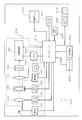
- FIG. 3 is a block diagram showing the configuration of the digital video camera 100.
- the digital video camera 100 captures a subject image formed by an optical system including a zoom lens 110 and the like with a CCD image sensor 180.
- the video data generated by the CCD image sensor 180 is subjected to various processes by the image processing unit 190 and stored in the memory card 240.
- the video data stored in the memory card 240 can be displayed on the liquid crystal monitor 270.
- the configuration of the digital video camera 100 will be described in detail.
- the optical system of the digital video camera 100 includes a zoom lens 110, an OIS 140 (Optical Image Stabilizer), and a focus lens 170.
- the zoom lens 110 can enlarge or reduce the subject image by moving along the optical axis of the optical system.
- the focus lens 170 adjusts the focus of the subject image by moving along the optical axis of the optical system.
- the focus motor 290 drives the focus lens 170.
- the OIS 140 includes a correction lens that can move in a plane perpendicular to the optical axis.
- the OIS 140 reduces the shake of the subject image by driving the correction lens in a direction that cancels the shake of the digital video camera 100.
- the zoom motor 130 drives the zoom lens 110.
- the zoom motor 130 may be realized by a pulse motor, a DC motor, a linear motor, a servo motor, or the like.
- the zoom motor 130 may drive the zoom lens 110 via a mechanism such as a cam mechanism or a ball screw.
- the detector 120 detects where the zoom lens 110 exists on the optical axis.
- the detector 120 outputs a signal related to the position of the zoom lens by a switch such as a brush in accordance with the movement of the zoom lens 110 in the optical axis direction.
- the OIS actuator 150 drives the correction lens in the OIS 140 in a plane perpendicular to the optical axis.
- the OIS actuator 150 can be realized by a planar coil or an ultrasonic motor.
- the detector 160 detects the amount of movement of the correction lens in the OIS 140.
- the CCD image sensor 180 captures a subject image formed by an optical system including the zoom lens 110 and generates video data.
- the CCD image sensor 180 performs various operations such as exposure, transfer, and electronic shutter.
- the image processing unit 190 performs various processes on the video data generated by the CCD image sensor 180.
- the image processing unit 190 performs processing on the video data generated by the CCD image sensor 180 to generate video data to be displayed on the liquid crystal monitor 270 or to store the video data in the memory card 240. Or generate.
- the image processing unit 190 performs various processes such as gamma correction, white balance correction, and flaw correction on the video data generated by the CCD image sensor 180. Further, the image processing unit 190 applies H.264 to the video data generated by the CCD image sensor 180.
- the video data is compressed by a compression format compliant with the H.264 standard or the MPEG2 standard.
- the image processing unit 190 can be realized by a DSP (Digital Signal Processor), a microcomputer, or the like.
- the controller 210 is a control means for controlling the whole.
- the controller 210 can be realized by a semiconductor element or the like.
- the controller 210 may be configured only by hardware, or may be realized by combining hardware and software.
- the controller 210 can be realized by a microcomputer or the like.
- the memory 200 functions as a work memory for the image processing unit 190 and the controller 210.
- the memory 200 can be realized by, for example, a DRAM or a ferroelectric memory.
- the liquid crystal monitor 270 can display an image indicated by the video data generated by the CCD image sensor 180 and an image indicated by the video data read from the memory card 240.
- the gyro sensor 220 is composed of a vibration material such as a piezoelectric element.
- the gyro sensor 220 obtains angular velocity information by converting a force due to the Coriolis force into a voltage by vibrating a vibrating material such as a piezoelectric element at a constant frequency.
- the digital video camera 100 corrects camera shake by driving the correction lens in the OIS 140 in a direction that cancels the shake indicated by the angular velocity information from the gyro sensor 220.
- the card slot 230 is detachable from the memory card 240.
- the card slot 230 can be mechanically and electrically connected to the memory card 240.
- the memory card 240 includes a flash memory, a ferroelectric memory, and the like, and can store data.
- the internal memory 280 is configured by a flash memory, a ferroelectric memory, or the like.
- the internal memory 280 stores a control program for controlling the entire digital video camera 100 and the like.
- the operation member 250 is a member that receives an operation from the user.
- the zoom lever 260 is a member that receives a zoom magnification change instruction from the user.
- the optical systems 110, 140, and 170, various devices 120, 130, 150, 160, and 290 for driving and controlling the optical systems 110, 140, and 170, the CCD image sensor 180, and the image processing unit 190 are illustrated.
- the memory 200 are defined as an imaging system 300.
- FIG. 4 is a schematic diagram for explaining contrast AF in the 2D mode.
- FIG. 5 is a schematic diagram for explaining contrast AF in the 3D mode.
- contrast AF in 2D mode will be described.
- the digital video camera 100 performs contrast AF using an image of a predetermined region (detection area) in the captured image. That is, the digital video camera 100 determines a range for setting a detection area in advance.
- the digital video camera 100 sets the center portion of the captured image as a detection area.
- the digital video camera 100 calculates an AF evaluation value (contrast value) based on the luminance value of the image in the detection area.
- the digital video camera 100 controls the focus lens 170 so that the AF evaluation value is maximized. This is the contrast AF in the 2D mode.
- contrast AF in 3D mode will be described.
- the digital video camera 100 sets the center portion of the left-eye image and the center portion of the right-eye image as detection areas as shown in FIG.
- the digital video camera 100 calculates an AF evaluation value (first AF evaluation value) for the left-eye image and an AF evaluation value (second AF evaluation value) for the right-eye image based on the luminance value of each detection area.
- an AF evaluation value (third AF evaluation value) for the 3D image is calculated.
- the digital video camera 100 performs contrast AF based on the AF evaluation value for 3D images.
- a method for calculating the AF evaluation value for the 3D image will be described later. Note that the AF evaluation value of the left-eye image and the AF evaluation value of the right-eye image are calculated by the same method as the AF evaluation value calculation method in the 2D mode.
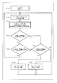
- FIG. 6 is a flowchart for explaining contrast AF control in the 3D mode.
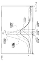
- FIG. 7 is a schematic diagram for explaining an AF evaluation value of a captured image.
- the user can set the digital video camera 100 to the shooting mode by operating the operation member 250 (S100).
- the controller 210 calculates the AF evaluation value of the left-eye image and the AF evaluation value of the right-eye image based on the captured image (the left-eye image and the right-eye image). (S110).
- the controller 210 calculates the product of the AF evaluation value of the left-eye image and the AF evaluation value of the right-eye image, Calculate (S120).
- the controller 210 calculates the product of the AF evaluation value of the left-eye image and the AF evaluation value of the right-eye image
- the controller 210 calculates the square root of the product (S120). Then, the controller 210 recognizes the value of the square root of the product of the AF evaluation value of the left-eye image and the AF evaluation value of the right-eye image as the AF evaluation value for the 3D image. In this way, the AF evaluation value for 3D images in the digital video camera 100 is calculated.
- the controller 210 determines whether or not the AF evaluation value for the 3D image is reliable data (S125).
- the controller 210 determines whether or not the AF evaluation value for the 3D image is reliable data (S125).
- the controller 210 determines whether or not the AF evaluation value for the 3D image is reliable data (S125).
- the amount of change in the AF evaluation value for the 3D image with respect to the change in the position of the focus lens 170 is large, it is determined that the AF evaluation value for the 3D image is reliable data.
- the amount of change in the AF evaluation value for the 3D image with respect to the change in the position of the focus lens 170 is small, it is determined that the AF evaluation value for the 3D image is not reliable data.
- the controller 210 determines whether or not the 3D image AF evaluation value is equal to or greater than a predetermined threshold value (reference value cr).
- the reference value cr is an index for determining whether or not the AF evaluation value for the 3D image is reliable data. As shown in FIG. 7, in the range where the AF evaluation value for the 3D image is equal to or greater than the reference value cr, the amount of change in the AF evaluation value for the 3D image is greater than or equal to a predetermined value. It is determined that the AF evaluation value for use is reliable data.
- the controller 210 performs the AF evaluation for the 3D image. Judge that the value is unreliable data.
- the controller 210 determines that the 3D image It is determined whether the change of the AF evaluation value for use is stable over time (S130). Specifically, the controller 210 determines whether or not the time change of the AF evaluation value for the 3D image is within a predetermined range. More specifically, the controller 210 determines whether or not the AF evaluation value for the 3D image in the current field with respect to the AF evaluation value for the 3D image in the previous field is less than a predetermined value.
- the controller 210 Performs again the processing after S110.
- the case where the change in the AF evaluation value for the 3D image is temporally stable corresponds to the case where the AF evaluation value for the 3D image is a value near the peak value. That is, in this case, the focus lens 170 is located in the vicinity of the lens position with respect to the peak of the AF evaluation value for the 3D image, that is, in the vicinity of the target lens position ps described later.
- the captured image changes with time in accordance with the temporal change of the subject. For this reason, when the process after S110 is performed after the process of S130, the AF evaluation value of the left-eye image and the AF evaluation value of the right-eye image generated in S110 according to the temporal change of the captured image are ,Change. That is, when the processes after S110 are repeatedly executed after the process of S130, the AF evaluation value for the 3D image repeatedly generated in S120 also changes.
- the controller 210 determines whether or not the AF evaluation value for the 3D image increases with time (S135). Specifically, the controller 210 determines whether or not the AF evaluation value for the 3D image in the current field is larger than the AF evaluation value for the 3D image one field before.
- the controller 210 moves the focus lens 170 in the current traveling direction until the drive direction of the focus lens 170 can be determined.
- the controller 210 drives the focus lens 170. To stop. Then, as described above, the controller 210 determines whether or not the AF evaluation value for the 3D image increases with time (S135).
- the controller 210 determines that the AF evaluation value for the 3D image is increasing with time (Yes in S135), the controller 210 moves the focus lens 170 by a predetermined amount in the current traveling direction. Drive (S136). On the other hand, if the controller 210 does not determine that the AF evaluation value for the 3D image is increasing with time (No in S135), the controller 210 moves the focus lens 170 in the opposite direction to the current traveling direction. Drive in the direction by a predetermined amount (S137). Then, when the driving of the focus lens 170 is completed, the controller 210 executes the processes after S110 again. A series of these processes (the processes of S110 to S137) are repeatedly executed by the controller 210 until shooting is stopped.
- the digital video camera 100 calculates the AF evaluation value for the 3D image based on the AF evaluation value for the left-eye image and the AF evaluation value for the right-eye image. did. The reason for this configuration will be described below.
- the focus lens 170 is set at a specific position. Thereby, the image for left eyes and the image for right eyes can be focused simultaneously. Specifically, when the focus lens 170 is at a specific position, the AF evaluation value of the left-eye image matches the AF evaluation value of the right-eye image. That is, in this case, the focus position of the left-eye image and the focus position of the right-eye image match.
- the left-eye lens 520 and the right-eye lens 510 of the 3D conversion lens 500 may be inclined within a very small range with respect to the imaging surface.
- the optical system in the digital video camera 100 may be tilted within a minute range with respect to the imaging surface.
- the focus lens 170 is in a specific position. Even so, the AF evaluation value of the image for the left eye and the AF evaluation value of the image for the right eye may be different as shown in FIG. That is, the in-focus position of the left-eye image is different from the in-focus position of the right-eye image.
- the AF evaluation value for the 3D image capable of appropriately displaying the 3D image is based on the AF evaluation value of the left-eye image and the AF evaluation value of the right-eye image. It was decided to calculate.
- the 3D image By using the AF evaluation value for the 3D image, the focus shift with respect to the image for the left eye and the image for the right eye is reduced. Therefore, when the 3D image is displayed based on the image for the left eye and the image for the right eye, the 3D image Is easy for the user to see.
- the horizontal axis in FIG. 7 corresponds to the optical axis of the optical system to which the focus lens 170 moves.
- the initial position of the focus lens 170 is indicated by symbol p1
- the position (maximum separation position) where the focus lens 170 is farthest from the initial position p1 is indicated by symbol p4.
- the lens position of the focus lens 170 with respect to the peak of the AF evaluation value of the image for the left eye is referred to as a first lens position p2
- the lens position of the focus lens 170 with respect to the peak of the AF evaluation value of the image for the right eye is defined as the second lens position.
- the midpoint between the first lens position p2 and the second lens position p3 is a lens position where the focus shift with respect to the image for the left eye and the image for the right eye is minimized, and this lens position is referred to as the optimum lens position pm.
- the first lens position p2 with respect to the peak of the AF evaluation value of the left-eye image and the AF evaluation value of the right-eye image Therefore, the second lens position p3 with respect to the peak no longer coincides.
- the AF evaluation value for the 3D image when the AF evaluation value for the 3D image is evaluated by 1/2 of the sum of the AF evaluation value for the left-eye image and the AF evaluation value for the right-eye image, the AF evaluation value for the 3D image (
- the AF evaluation value (arithmetic mean) for the 3D image) is affected by the higher AF evaluation value (the AF evaluation value of the left-eye image or the AF evaluation value of the right-eye image), for example, the left eye in FIG. This is strongly influenced by the AF evaluation value of the image for use.
- the lens position pw with respect to the peak of the AF evaluation value (arithmetic mean) for the 3D image approaches the first lens position p2.
- the lens position pw of the focus lens 170 is separated from the optimum lens position pm. For this reason, when the focus lens 170 is moved toward the lens position pw based on the AF evaluation value (arithmetic mean) for the 3D image, the focus shift between the left-eye image and the right-eye image becomes large. There is a risk that.
- the distance between the lens position pw of the focus lens 170 and the optimum lens position pm is indicated by the symbol dw.
- the AF evaluation value for the 3D image is evaluated by the square root of the product of the AF evaluation value of the left-eye image and the AF evaluation value of the right-eye image
- the peak value of the AF evaluation value of the left-eye image Even if the absolute value of the difference from the peak value of the AF evaluation value of the right-eye image increases, this AF evaluation value for the 3D image (hereinafter referred to as the AF evaluation value (3D image geometrical mean) for the 3D image)
- the AF evaluation value 3D image geometrical mean
- the influence of the higher AF evaluation value (the AF evaluation value of the left-eye image or the AF evaluation value of the right-eye image), for example, the influence of the AF evaluation value of the left-eye image in FIG.
- the AF evaluation value (synergistic average) for the 3D image is used in comparison with the AF evaluation value (arithmetic average) for the 3D image.
- the lens position ps (hereinafter referred to as the target lens position) with respect to the peak of (average) approaches the optimum lens position pm. Specifically, as shown in FIG. 7, the distance ds between the target lens position ps and the optimum lens position pm is smaller than the distance dw between the lens position pw and the optimum lens position pm.
- the lens position of the focus lens 170 is set based on the AF evaluation value (geometric average) for 3D images.
- control at the time of generating a 3D moving image and the control at the time of generating a 3D still image will be described.
- the first embodiment described above can be applied to both control at the time of generating a 3D still image and control at the time of generating a 3D moving image.
- the driving of the focus lens 170 can be more effectively controlled when the first embodiment is applied to a 3D moving image than when the first embodiment is applied to a 3D still image.
- control of the focus lens 170 will be described with reference to FIG.
- the first lens position p2 and the second lens position p3 do not match.
- the focus lens 170 is set to one of the first lens position p2 and the second lens position p3, a large focus shift occurs between the right-eye image and the left-eye image. That is, the video becomes very difficult to view as a 3D image. In order to solve this problem, it is important to minimize the focus shift with respect to the right-eye image and the left-eye image.
- the controller 210 arbitrarily moves the focus lens 170 along the optical axis of the optical system to distribute the AF evaluation value of the right-eye image and the AF evaluation of the left-eye image.
- the distribution of values can be determined.
- FIG. 7 is interpreted as a 3D still image AF evaluation value diagram
- the controller 210 moves the focus lens 170 in the entire range of the horizontal axis in FIG. A distribution of values and a distribution of AF evaluation values of the image for the right eye are generated.
- the controller 210 detects the first lens position p2 and the second lens position p3 based on the distribution of the AF evaluation values of the left-eye image and the distribution of the AF evaluation values of the right-eye image. Then, the controller 210 sets the focus lens 170 at the midpoint position between the first lens position p2 and the second lens position p3, that is, the optimum lens position pm. In this way, in the case of a 3D still image, the degree of focus deviation with respect to the right-eye image and the left-eye image can be reduced.
- the focus lens 170 is arbitrarily moved along the optical axis of the optical system to distribute the AF evaluation value of the left-eye image and the right-eye image.
- the distribution of AF evaluation values is not obtained. This is because, for example, in order to generate the distribution of the AF evaluation values of the image for the left eye and the distribution of the AF evaluation values of the image for the right eye, the focus lens 170 is moved over the entire range of the optical axis of the optical system (horizontal in FIG.
- the focus lens 170 is not set to the optimum lens position pm. That is, in the case of a 3D moving image, the drive of the focus lens 170 cannot be controlled in the same manner as in the case of a 3D still image.
- the controller 210 determines that the focus lens 170 is moving toward the peaks of the two AF evaluation values, and moves the focus lens 170 in the current traveling direction (right direction in FIG. 7).
- the controller 210 determines that the focus lens 170 is moving in a direction away from the peaks of the two AF evaluation values, and moves the focus lens 170 in a direction opposite to the current traveling direction (FIG. 7). To the right).
- the controller 210 determines that the focus lens 170 is moving in a direction away from the peaks of the two AF evaluation values, and moves the focus lens 170 in a direction opposite to the current traveling direction (FIG. 7). To the left).
- the controller 210 determines that the focus lens 170 is moving toward the peaks of the two AF evaluation values, and moves the focus lens 170 in the current traveling direction (left direction in FIG. 7).
- the controller 210 cannot determine whether the focus lens 170 should be moved in the current traveling direction or in a direction opposite to the current traveling direction. That is, in this case, the controller 210 cannot determine the lens position of the focus lens 170. For this reason, the method used in the conventional moving image cannot control the driving of the focus lens 170 for the 3D moving image.
- the focus lens 170 is controlled by the controller 210 so that this problem can be solved.
- a new evaluation value that is, an AF evaluation value for a 3D image
- the AF evaluation value (geometric mean) for the 3D image is generated.
- the controller 210 controls the driving of the focus lens 170 based on the AF evaluation value for the 3D image.
- the controller 210 since there is only one 3D image AF evaluation value (an AF evaluation value at a certain time) for a certain lens position on the horizontal axis in FIG. 7, the controller 210 performs AF for 3D images.
- the focus lens 170 can be moved in accordance with the increase / decrease of the evaluation value, and the lens position of the focus lens 170 can be determined. For example, when the focus lens 170 is located between the initial position p1 and the target lens position ps and moves from left to right on the horizontal axis, the AF evaluation value for the 3D image increases.
- the controller 210 determines that the focus lens 170 is moving toward the peak of the AF evaluation value for the 3D image, and moves the focus lens 170 in the current traveling direction (right direction in FIG. 7). To do. In this state, when the focus lens 170 moves from right to left on the horizontal axis, the AF evaluation value for the 3D image decreases. In this case, the controller 210 determines that the focus lens 170 is moving in a direction away from the peak of the AF evaluation value for 3D images, and moves the focus lens 170 in a direction opposite to the current traveling direction ( Move to the right in FIG.
- the controller 210 determines that the focus lens 170 is moving in a direction away from the peak of the AF evaluation value for the 3D image, and moves the focus lens 170 in a direction opposite to the current traveling direction (see FIG. 7). Move left). In this state, if the focus lens 170 moves from right to left, the AF evaluation value for the 3D image increases, so the controller 210 moves the focus lens 170 toward the peak of the AF evaluation value for the 3D image. The focus lens 170 is moved in the current traveling direction (left direction in FIG. 7).
- the entire range along the optical axis of the optical system (from the initial position p1 in FIG. 7 to the maximum separation position p4). In the entire range), the lens position of the focus lens 170 can be set reliably.
- the controller 210 can always move the focus lens 170 toward the target lens position ps, it is possible to reduce a focus shift with respect to the right-eye image and the left-eye image.
- FIG. 3 illustrates the optical system 110, 140, 170 having a three-group configuration, but a lens configuration having another group configuration may be used.
- each of the lenses 110, 140, and 170 of the optical system shown in FIG. 3 may be configured as a single lens or a lens group including a plurality of lenses.
- Embodiment 1 an example in which a 3D image is captured with the 3D conversion lens 500 attached to the digital video camera 100 has been described, but the present invention is not limited to this.
- the right-eye lens 510 and the left-eye lens 520 may be built in the digital video camera 100.
- the imaging system 300 shown in FIG. 3 is prepared for each of the lenses 510 and 520. That is, the digital video camera 100 is provided with two imaging systems 300. In this case, each imaging system 300 generates two images, that is, a left-eye image and a right-eye image. Then, the processing from S110 to S140 is executed for each of the left-eye image and the right-eye image.
- the present invention can be realized as in the first embodiment.
- the CCD image sensor 180 is exemplified as the imaging unit, but the present invention is not limited to this.
- it may be composed of a CMOS image sensor or an NMOS image sensor.
- the product of the AF evaluation value of the left-eye image and the AF evaluation value of the right-eye image is calculated, the square root is obtained, and the AF evaluation value for the 3D image It was decided to.
- it is not necessarily limited to such a configuration.
- the AF evaluation value of the left-eye image and the AF evaluation value of the right-eye image may be calculated and used as an AF evaluation value for a 3D image.
- the AF evaluation value for the 3D image may be calculated based on the AF evaluation value for the left-eye image and the AF evaluation value for the right-eye image.
- the present invention can be applied to any range in which the detection area is set in the left-eye image and the right-eye image.
- the present invention can be applied to an imaging apparatus such as a digital video camera or a digital still camera.
Landscapes
- Physics & Mathematics (AREA)
- General Physics & Mathematics (AREA)
- Engineering & Computer Science (AREA)
- Multimedia (AREA)
- Signal Processing (AREA)
- Computer Vision & Pattern Recognition (AREA)
- Optics & Photonics (AREA)
- Automatic Focus Adjustment (AREA)
- Testing, Inspecting, Measuring Of Stereoscopic Televisions And Televisions (AREA)
- Focusing (AREA)
- Stereoscopic And Panoramic Photography (AREA)
- Studio Devices (AREA)
Abstract
Description
本発明は、サイドバイサイド形式の3D画像を撮像する際に、左目用の画像と右目用の画像に対する合焦ずれを小さくできる撮像装置を提供することを、目的とする。
〔1.実施の形態1〕
〔1-1.概要〕
本実施の形態1にかかるデジタルビデオカメラ100の概要について図1、図2を用いて説明する。図1は、デジタルビデオカメラ100に3Dコンバージョンレンズ500を取り付けた状態を示す斜視図である。図2は、3Dコンバージョンレンズ500を取り付けた状態のデジタルビデオカメラ100が撮像する画像データを説明するための模式図である。
3Dコンバージョンレンズ500は、デジタルビデオカメラ100が有する取付部(図示せず)に対して、着脱可能である。デジタルビデオカメラ100は、3Dコンバージョンレンズ500の取り付けを、検出スイッチ(図示せず)により磁気的に検出する。
3Dコンバージョンレンズ500を介して入射した光は、デジタルビデオカメラ100のCCDイメージセンサー180上に、図2に示すようなサイドバイサイド形式の3D画像として、結像される。つまり、デジタルビデオカメラ100では、3Dコンバージョンレンズ500を取り付けた状態で(3Dモードで)、サイドバイサイド形式の3D画像が撮像される。また、デジタルビデオカメラ100では、3Dコンバージョンレンズ500を取り外した状態で(2Dモードで)、2D画像が撮像される。
〔1-2.構成〕
本実施の形態1にかかるデジタルビデオカメラ100の電気的構成について、図3を用いて説明する。図3は、デジタルビデオカメラ100の構成を示すブロック図である。デジタルビデオカメラ100は、ズームレンズ110等からなる光学系により形成された被写体像をCCDイメージセンサー180で撮像する。CCDイメージセンサー180で生成された映像データは、画像処理部190で各種処理が施され、メモリカード240に格納される。また、メモリカード240に格納された映像データは、液晶モニタ270で表示可能である。以下、デジタルビデオカメラ100の構成を詳細に説明する。
OIS140は、内部に光軸に垂直な面内で移動可能な補正レンズを有する。OIS140は、デジタルビデオカメラ100の振れを相殺する方向に補正レンズを駆動することにより、被写体像の振れを低減する。
ズームモータ130は、ズームレンズ110を駆動する。ズームモータ130は、パルスモータやDCモータ、リニアモータ、サーボモータなどで実現してもよい。ズームモータ130は、カム機構やボールネジなどの機構を介してズームレンズ110を駆動するようにしてもよい。検出器120は、ズームレンズ110が光軸上でどの位置に存在するのかを検出する。検出器120は、ズームレンズ110の光軸方向への移動に応じて、ブラシ等のスイッチによりズームレンズの位置に関する信号を出力する。
CCDイメージセンサー180は、ズームレンズ110等からなる光学系で形成された被写体像を撮像して、映像データを生成する。CCDイメージセンサー180は、露光、転送、電子シャッタなどの各種動作を行う。
画像処理部190は、CCDイメージセンサー180で生成された映像データに対して各種の処理を施す。画像処理部190は、CCDイメージセンサー180で生成された映像データに対して処理を施すことによって、液晶モニタ270に表示するための映像データを生成したり、メモリカード240に格納するための映像データを生成したりする。例えば、画像処理部190は、CCDイメージセンサー180で生成された映像データに対して、ガンマ補正、ホワイトバランス補正、傷補正などの各種処理を行う。また、画像処理部190は、CCDイメージセンサー180で生成された映像データに対して、H.264規格やMPEG2規格に準拠した圧縮形式等により映像データを圧縮する。画像処理部190は、DSP(Digital Signal Processor)やマイコンなどで実現可能である。
メモリ200は、画像処理部190及びコントローラー210のワークメモリとして機能する。メモリ200は、例えば、DRAM、強誘電体メモリなどで実現できる。
液晶モニタ270は、CCDイメージセンサー180で生成した映像データが示す画像や、メモリカード240から読み出した映像データが示す画像を表示可能である。
ジャイロセンサー220は、圧電素子等の振動材等で構成される。ジャイロセンサー220は、圧電素子等の振動材を一定周波数で振動させることによって、コリオリ力による力を電圧に変換して角速度情報を得る。ジャイロセンサー220からの角速度情報が示す揺れを相殺する方向に、OIS140内の補正レンズを駆動させることにより、デジタルビデオカメラ100は手振れを補正する。
内部メモリ280は、フラッシュメモリや強誘電体メモリなどで構成される。内部メモリ280は、デジタルビデオカメラ100全体を制御するための制御プログラム等を格納する。
操作部材250は、使用者から操作を受け付ける部材である。ズームレバー260は、使用者からズーム倍率の変更指示を受け付ける部材である。
なお、本実施形態では、光学系110,140,170、光学系110,140,170を駆動及び制御するための各種装置120,130,150,160,290、CCDイメージセンサー180、画像処理部190、及びメモリ200を、撮像系300と定義する。
コントラストAFについて図4、図5を用いて説明する。図4は、2DモードにおけるコントラストAFを説明するための模式図である。図5は、3DモードにおけるコントラストAFを説明するための模式図である。
まず、2DモードにおけるコントラストAFについて説明する。デジタルビデオカメラ100は、撮像画像のうち予め定められた領域(検波エリア)の画像を用いて、コントラストAFを行う。つまり、デジタルビデオカメラ100は、予め検波エリアを設定する範囲を決めている。デジタルビデオカメラ100は、2Dモードにおいて、撮像画像の中央部分を検波エリアとして設定している。デジタルビデオカメラ100は、検波エリア内の画像の輝度値に基づいて、AF評価値(コントラスト値)を算出する。デジタルビデオカメラ100は、このAF評価値が最大となるように、フォーカスレンズ170を制御する。これが2DモードにおけるコントラストAFである。
3DモードにおけるコントラストAF制御について図6、7を用いて説明する。図6は、3DモードにおけるコントラストAF制御を説明するためのフローチャートである。図7は、撮像画像のAF評価値について説明するための模式図である。
使用者は操作部材250を操作することにより、デジタルビデオカメラ100は、撮影モードに設定できる(S100)。デジタルビデオカメラ100が撮影モードに設定されると、コントローラー210は、撮像画像(左目用画像及び右目用画像)に基づいて、左目用画像のAF評価値と右目用画像のAF評価値とを算出する(S110)。
ここで、コントローラー210が左目用画像のAF評価値と右目用画像のAF評価値とを算出すると、コントローラー210は、左目用画像のAF評価値と右目用画像のAF評価値との積を、算出する(S120)。そして、コントローラー210が左目用画像のAF評価値と右目用画像のAF評価値との積を算出すると、コントローラー210は、積の平方根を算出する(S120)。そして、コントローラー210は、左目用画像のAF評価値と右目用画像のAF評価値との積の平方根の値を、3D画像用のAF評価値として、認識する。このようにして、デジタルビデオカメラ100における3D画像用のAF評価値が、算出される。
具体的には、S125では、コントローラー210は、3D画像用のAF評価値が所定の閾値(基準値cr)以上であるか否かを、判断する。基準値crは、3D画像用のAF評価値が信頼性のあるデータであるか否かを判断するための指標である。図7に示すように、3D画像用のAF評価値が基準値cr以上である範囲では、上記の3D画像用のAF評価値の変化量が所定値以上になるので、コントローラー210は、3D画像用のAF評価値が信頼性のあるデータであると判断する。一方で、3D画像用のAF評価値が基準値cr未満である範囲では、上記の3D画像用のAF評価値の変化量が所定値未満になるので、コントローラー210は、3D画像用のAF評価値が信頼性のないデータであると判断する。
ここで、3D画像用のAF評価値の変化が時間的に安定していた場合、例えば3D画像用のAF評価値の時間変化が、所定値未満であった場合(S130でYes)、コントローラー210は、S110以降の処理を再び実行する。ここで、3D画像用のAF評価値の変化が時間的に安定している場合は、3D画像用のAF評価値がピーク値近傍の値である場合に、対応する。すなわち、この場合は、フォーカスレンズ170は、3D画像用のAF評価値のピークに対するレンズ位置の近傍、すなわち後述する目標レンズ位置psの近傍に、位置している。
一方で、3D画像用のAF評価値が信頼性のないデータである場合(S125でNo)、又は3D画像用のAF評価値の変化が時間的に安定していない場合(S130でNo)、コントローラー210は、3D画像用のAF評価値が時間的に増加しているか否かを、判断する(S135)。具体的には、コントローラー210は、現在のフィールドの3D画像用のAF評価値が、1フィールド前の3D画像用のAF評価値より大きいか否かを、判断する。
これら一連の処理(S110~S137の処理)は、撮影が停止されるまで、コントローラー210により繰り返し実行される。
このように、本実施の形態1にかかるデジタルビデオカメラ100は、3D画像用のAF評価値を、左目用画像のAF評価値と右目用画像のAF評価値とに基づいて、算出することとした。このように構成した理由を、以下に説明する。
そこで、本実施の形態1にかかるデジタルビデオカメラ100では、3D画像を適切に表示可能な3D画像用のAF評価値を、左目用画像のAF評価値と右目用画像のAF評価値とに基づいて、算出することとした。この3D画像用のAF評価値を用いることによって、左目用画像と右目用画像とに対する合焦ずれは小さくなるので、左目用画像と右目用画像とに基づいて3D画像を表示した場合、3D画像が使用者にとって見やすいものとなる。
上述したように、左目用レンズ520と右目用レンズ510とが撮像面に対して傾いてしまうと、左目用画像のAF評価値のピークに対する第1レンズ位置p2と、右目用画像のAF評価値のピークに対する第2レンズ位置p3とが一致しなくなってしまう。この状態で、左目用画像のAF評価値と右目用画像のAF評価値とが算出されると、図7に示すように、左目用画像のAF評価値のピーク値と右目用画像のAF評価値のピーク値との差の絶対値が大きくなることが多い。
このため、3D画像用のAF評価値(相乗平均)を用いた場合は、3D画像用のAF評価値(相加平均)を用いた場合と比較して、3D画像用のAF評価値(相乗平均)のピークに対するレンズ位置ps(以下、目標レンズ位置と呼ぶ)は、最適レンズ位置pmに近づく。具体的には、図7に示すように、目標レンズ位置psと最適レンズ位置pmとの距離dsが、レンズ位置pwと最適レンズ位置pmとの距離dwより小さくなる。このため、3D画像用のAF評価値(相乗平均)に基づいて、フォーカスレンズ170のレンズ位置を目標レンズ位置psに向けて移動する場合、左目用画像と右目用画像とに対する合焦ずれを、小さくすることができる。このような理由から、本実施の形態1では、3D画像用のAF評価値(相乗平均)に基づいて、フォーカスレンズ170のレンズ位置を設定している。
上述したように、左目用レンズ520と右目用レンズ510とが撮像面に対して傾いてしまうと、第1レンズ位置p2と第2レンズ位置p3とが一致しなくなってしまう。ここで、フォーカスレンズ170を、第1レンズ位置p2及び第2レンズ位置p3のいずれか一方に設定すると、右目用画像と左目用画像との間に大きな合焦ずれが発生してしまう。すなわち、3D画像として非常に見づらい映像になってしまう。この問題を解決するためには、右目用画像と左目用画像とに対する合焦ずれを極力小さくすることが重要となる。
すると、これら左目用画像のAF評価値の分布及び右目用画像のAF評価値の分布に基づいて、コントローラー210は、第1レンズ位置p2と第2レンズ位置p3とを検出する。そして、コントローラー210は、第1レンズ位置p2と第2レンズ位置p3との中点の位置、すなわち最適レンズ位置pmに、フォーカスレンズ170を設定する。このようにして、3D静止画の場合は、右目用画像と左目用画像とに対する合焦ずれの程度を、小さくすることができる。
このことから、3D動画の場合は、左目用画像のAF評価値の分布、及び右目用画像のAF評価値の分布に基づいて、第1レンズ位置p2と第2レンズ位置p3とが検出されることはなく、フォーカスレンズ170が最適レンズ位置pmに設定されることもない。すなわち、3D動画の場合は、3D静止画の場合と同様の形態で、フォーカスレンズ170の駆動を制御することができない。
そこで、本実施の形態1では、この問題を解決することができるように、フォーカスレンズ170がコントローラー210によって制御される。例えば、まず、左目用画像のAF評価値及び右目用画像のAF評価値に基づいて、新たな評価値すなわち3D画像用のAF評価値が生成される。具体的には、上述したように、左目用画像のAF評価値と右目用画像のAF評価値との積の平方根を計算することによって、3D画像用のAF評価値(相乗平均)が生成される。
例えば、フォーカスレンズ170が、初期位置p1と目標レンズ位置psとの間に位置した状態で、横軸上を左から右へと移動した場合、3D画像用のAF評価値は増加する。この場合、コントローラー210は、フォーカスレンズ170が3D画像用のAF評価値のピークに向けて移動しているものと判断し、フォーカスレンズ170を、現在の進行方向(図7の右方向)に移動する。また、この状態で、フォーカスレンズ170が横軸上を右から左へと移動した場合、3D画像用のAF評価値は減少する。この場合、コントローラー210は、フォーカスレンズ170が3D画像用のAF評価値のピークから離れる方向に向けて移動しているものと判断し、フォーカスレンズ170を、現在の進行方向とは反対の方向(図7の右方向)に移動する。
このように、本実施の形態1では、新たな評価値すなわち3D画像用のAF評価値を用いることによって、光学系の光軸に沿った全範囲(図7の初期位置p1から最大離反位置p4までの全範囲)において、フォーカスレンズ170のレンズ位置を、確実に設定することができる。また、コントローラー210は、フォーカスレンズ170を常に目標レンズ位置psに向けて移動することができるので、右目用画像と左目用画像とに対する合焦ずれを小さくすることができる。
〔2.他の実施の形態〕
以上により、本発明の実施の形態として、実施の形態1を説明した。しかし、本発明は、これらには限定されない。そこで、本発明の他の実施の形態を、以下にまとめて説明する。
また、実施の形態1では、3Dコンバージョンレンズ500を、デジタルビデオカメラ100に取り付けた状態で、3D画像が撮像される場合の例を示したが、本発明はこれに限定されない。例えば、右眼用レンズ510と左眼用レンズ520とを、デジタルビデオカメラ100に内蔵する構成にしてもよい。この場合、デジタルビデオカメラ100には、図3に示した撮像系300が、各レンズ510,520に対して用意される。すなわち、デジタルビデオカメラ100には、2系統の撮像系300が用意される。この場合、各撮像系300によって、2つの画像、すなわち左目用画像と右目用画像とが、生成される。そして、左目用画像及び右目用画像それぞれに対して、S110からS140までの処理が、実行される。このように、右眼用レンズ510と左眼用レンズ520とを、デジタルビデオカメラ100に内蔵した場合においても、実施の形態1と同様に、本発明を実現することができる。
また、実施の形態1では、3DモードにおけるコントラストAFの際に、左目用画像のAF評価値と右目用画像のAF評価値との積を算出し、平方根を求め3D画像用のAF評価値とすることとした。しかしながら、必ずしもこのような構成に限定されない。例えば、左目用画像のAF評価値のピーク値と右目用画像のAF評価値のピーク値との差の絶対値が小さい場合は、左目用画像のAF評価値と右目用画像のAF評価値との平均値を算出し、3D画像用のAF評価値とするような構成であってもよい。要するに、左目用画像のAF評価値と右目用画像のAF評価値とに基づいて3D画像用のAF評価値を算出すればよい。
110 ズームレンズ
120 検出器
130 ズームモータ
140 OIS
150 OISアクチュエータ
160 検出器
170 フォーカスレンズ
180 CCDイメージセンサー
190 画像処理部
200 メモリ
210 コントローラー
220 ジャイロセンサー
230 カードスロット
240 メモリカード
250 操作部材
260 ズームレバー
270 液晶モニタ
280 内部メモリ
Claims (7)
- フォーカスレンズを含む光学系と、
左目用の像と右目用の像とを前記光学系を介して撮像する撮像手段と、
前記撮像手段により撮像された画像に含まれる前記左目用の像に基づいて生成された画像に対する第1AF評価値と、前記撮像手段により撮像された画像に含まれる前記右目用の像に基づいて生成された画像に対する第2AF評価値とに基づいて、第3AF評価値を生成し、前記第3AF評価値に基づいて前記フォーカスレンズの駆動を制御する制御手段と、
を備える撮像装置。 - 前記制御手段は、前記第1AF評価値と前記第2AF評価値との積に基づいて生成された前記第3AF評価値に基づいて、前記フォーカスレンズの駆動を制御する、
請求項1に記載の撮像装置。 - 前記制御手段は、前記積の平方根に対応する前記第3AF評価値に基づいて、前記フォーカスレンズの駆動を制御する、
請求項2に記載の撮像装置。 - 前記制御手段は、前記フォーカスレンズを、前記第3AF評価値が増える方向に駆動する、
請求項3に記載の撮像装置。 - 前記撮像手段により撮像された前記画像を、格納する記録部、
をさらに備え、
前記制御手段は、ある時刻における前記第3AF評価値に基づいて、次の時刻のフォーカスレンズの位置を設定し、
前記記録部は、前記フォーカスレンズを前記位置に設定した状態で撮像された前記画像を格納する、
請求項1から3のいずれかに記載の撮像装置。 - 前記左目用の像に対応する光と前記右目用の像に対応する光とを出力する像出力手段と、撮像装置本体とを、有する撮像装置であって、
前記撮像装置本体は、前記左目用の像に対応する光と前記右目用の像に対応する光とが入力される前記光学系と、前記撮像手段と、前記制御手段とを、備える、
請求項1から5のいずれかに記載の撮像装置。 - 前記左目用の像に対応する光と前記右目用の像に対応する光とを出力する像出力手段、
をさらに備え、
前記撮像手段は、前記左目用の像に対応する前記光と前記右目用の像に対応する前記光とが入力される前記光学系を介して、前記左目用の像と前記右目用の像とを撮像する、
請求項1から5のいずれかに記載の撮像装置。
Priority Applications (3)
| Application Number | Priority Date | Filing Date | Title |
|---|---|---|---|
| JP2012527567A JPWO2012017585A1 (ja) | 2010-08-06 | 2011-05-26 | 撮像装置 |
| CN2011800385371A CN103069324A (zh) | 2010-08-06 | 2011-05-26 | 摄像装置 |
| US13/760,001 US20130147920A1 (en) | 2010-08-06 | 2013-02-05 | Imaging device |
Applications Claiming Priority (2)
| Application Number | Priority Date | Filing Date | Title |
|---|---|---|---|
| JP2010178139 | 2010-08-06 | ||
| JP2010-178139 | 2010-08-06 |
Related Child Applications (1)
| Application Number | Title | Priority Date | Filing Date |
|---|---|---|---|
| US13/760,001 Continuation US20130147920A1 (en) | 2010-08-06 | 2013-02-05 | Imaging device |
Publications (1)
| Publication Number | Publication Date |
|---|---|
| WO2012017585A1 true WO2012017585A1 (ja) | 2012-02-09 |
Family
ID=45559111
Family Applications (1)
| Application Number | Title | Priority Date | Filing Date |
|---|---|---|---|
| PCT/JP2011/002941 Ceased WO2012017585A1 (ja) | 2010-08-06 | 2011-05-26 | 撮像装置 |
Country Status (4)
| Country | Link |
|---|---|
| US (1) | US20130147920A1 (ja) |
| JP (1) | JPWO2012017585A1 (ja) |
| CN (1) | CN103069324A (ja) |
| WO (1) | WO2012017585A1 (ja) |
Cited By (1)
| Publication number | Priority date | Publication date | Assignee | Title |
|---|---|---|---|---|
| WO2013190814A1 (ja) * | 2012-06-22 | 2013-12-27 | 株式会社ニコン | 画像処理装置、撮像装置および画像処理プログラム |
Families Citing this family (2)
| Publication number | Priority date | Publication date | Assignee | Title |
|---|---|---|---|---|
| WO2013027343A1 (ja) * | 2011-08-23 | 2013-02-28 | パナソニック株式会社 | 3次元撮像装置、レンズ制御装置、およびプログラム |
| CN105629442B (zh) * | 2016-03-29 | 2018-08-17 | 镇江磐禾商贸有限公司 | 摄像光学镜头组 |
Citations (3)
| Publication number | Priority date | Publication date | Assignee | Title |
|---|---|---|---|---|
| JPS62169131A (ja) * | 1986-01-21 | 1987-07-25 | Sony Corp | カメラ |
| JPH07104400A (ja) * | 1993-10-07 | 1995-04-21 | Asahi Optical Co Ltd | ステレオ写真撮影装置 |
| JP2005173270A (ja) * | 2003-12-11 | 2005-06-30 | Canon Inc | 立体撮影用光学装置、撮影装置、立体撮影システム及び立体撮影装置 |
Family Cites Families (6)
| Publication number | Priority date | Publication date | Assignee | Title |
|---|---|---|---|---|
| US7604348B2 (en) * | 2001-01-23 | 2009-10-20 | Kenneth Martin Jacobs | Continuous adjustable 3deeps filter spectacles for optimized 3deeps stereoscopic viewing and its control method and means |
| US8369607B2 (en) * | 2002-03-27 | 2013-02-05 | Sanyo Electric Co., Ltd. | Method and apparatus for processing three-dimensional images |
| JP4398197B2 (ja) * | 2003-08-20 | 2010-01-13 | オリンパス株式会社 | カメラ |
| EP1821128B1 (en) * | 2004-11-16 | 2011-03-16 | Citizen Holdings Co., Ltd. | Automatic focusing apparatus |
| JP2008009342A (ja) * | 2006-06-30 | 2008-01-17 | Sony Corp | オートフォーカス装置、撮像装置及びオートフォーカス方法 |
| JP2012027263A (ja) * | 2010-07-23 | 2012-02-09 | Sony Corp | 撮像装置、その制御方法およびプログラム |
-
2011
- 2011-05-26 JP JP2012527567A patent/JPWO2012017585A1/ja not_active Withdrawn
- 2011-05-26 CN CN2011800385371A patent/CN103069324A/zh active Pending
- 2011-05-26 WO PCT/JP2011/002941 patent/WO2012017585A1/ja not_active Ceased
-
2013
- 2013-02-05 US US13/760,001 patent/US20130147920A1/en not_active Abandoned
Patent Citations (3)
| Publication number | Priority date | Publication date | Assignee | Title |
|---|---|---|---|---|
| JPS62169131A (ja) * | 1986-01-21 | 1987-07-25 | Sony Corp | カメラ |
| JPH07104400A (ja) * | 1993-10-07 | 1995-04-21 | Asahi Optical Co Ltd | ステレオ写真撮影装置 |
| JP2005173270A (ja) * | 2003-12-11 | 2005-06-30 | Canon Inc | 立体撮影用光学装置、撮影装置、立体撮影システム及び立体撮影装置 |
Cited By (4)
| Publication number | Priority date | Publication date | Assignee | Title |
|---|---|---|---|---|
| WO2013190814A1 (ja) * | 2012-06-22 | 2013-12-27 | 株式会社ニコン | 画像処理装置、撮像装置および画像処理プログラム |
| CN104322061A (zh) * | 2012-06-22 | 2015-01-28 | 株式会社尼康 | 图像处理装置、摄像装置及图像处理程序 |
| JPWO2013190814A1 (ja) * | 2012-06-22 | 2016-02-08 | 株式会社ニコン | 画像処理装置、撮像装置および画像処理プログラム |
| CN104322061B (zh) * | 2012-06-22 | 2017-01-18 | 株式会社尼康 | 图像处理装置、摄像装置及图像处理方法 |
Also Published As
| Publication number | Publication date |
|---|---|
| US20130147920A1 (en) | 2013-06-13 |
| CN103069324A (zh) | 2013-04-24 |
| JPWO2012017585A1 (ja) | 2013-09-19 |
Similar Documents
| Publication | Publication Date | Title |
|---|---|---|
| CN103748493B (zh) | 摄像装置以及其控制方法 | |
| US9491439B2 (en) | Three-dimensional image capture device, lens control device and program | |
| JP5597525B2 (ja) | 立体映像撮像装置および立体映像撮像方法 | |
| JP5688543B2 (ja) | 立体画像撮像装置および立体画像撮像装置におけるレンズ駆動方法 | |
| WO2012014355A1 (ja) | 撮像装置 | |
| JP6659100B2 (ja) | 撮像装置 | |
| JP6432038B2 (ja) | 撮像装置 | |
| US20130050532A1 (en) | Compound-eye imaging device | |
| US20130027520A1 (en) | 3d image recording device and 3d image signal processing device | |
| US20130050536A1 (en) | Compound-eye imaging device | |
| JP2012063751A (ja) | 撮像装置 | |
| WO2014141653A1 (ja) | 画像生成装置、撮像装置および画像生成方法 | |
| WO2012017585A1 (ja) | 撮像装置 | |
| JP4857006B2 (ja) | カメラシステム | |
| US20130076867A1 (en) | Imaging apparatus | |
| WO2011086898A1 (ja) | 3d画像撮影装置及びその制御方法 | |
| KR20130047343A (ko) | 카메라 모듈 및 그의 3차원 사진 획득 방법 | |
| JP2012220603A (ja) | 3d映像信号撮影装置 | |
| US20120033050A1 (en) | Imaging apparatus | |
| US20130135436A1 (en) | Imaging apparatus | |
| JP2013145372A (ja) | 撮像装置 | |
| US20120212585A1 (en) | Stereoscopic imaging device and stereoscopic imaging method | |
| JP2013044845A (ja) | 撮像装置 |
Legal Events
| Date | Code | Title | Description |
|---|---|---|---|
| WWE | Wipo information: entry into national phase |
Ref document number: 201180038537.1 Country of ref document: CN |
|
| 121 | Ep: the epo has been informed by wipo that ep was designated in this application |
Ref document number: 11814225 Country of ref document: EP Kind code of ref document: A1 |
|
| DPE1 | Request for preliminary examination filed after expiration of 19th month from priority date (pct application filed from 20040101) | ||
| WWE | Wipo information: entry into national phase |
Ref document number: 2012527567 Country of ref document: JP |
|
| NENP | Non-entry into the national phase |
Ref country code: DE |
|
| 122 | Ep: pct application non-entry in european phase |
Ref document number: 11814225 Country of ref document: EP Kind code of ref document: A1 |