WO2012014959A1 - Glass film laminate - Google Patents
Glass film laminate Download PDFInfo
- Publication number
- WO2012014959A1 WO2012014959A1 PCT/JP2011/067215 JP2011067215W WO2012014959A1 WO 2012014959 A1 WO2012014959 A1 WO 2012014959A1 JP 2011067215 W JP2011067215 W JP 2011067215W WO 2012014959 A1 WO2012014959 A1 WO 2012014959A1
- Authority
- WO
- WIPO (PCT)
- Prior art keywords
- glass film
- support
- glass
- film
- thin
- Prior art date
Links
Images


Classifications
-
- B—PERFORMING OPERATIONS; TRANSPORTING
- B32—LAYERED PRODUCTS
- B32B—LAYERED PRODUCTS, i.e. PRODUCTS BUILT-UP OF STRATA OF FLAT OR NON-FLAT, e.g. CELLULAR OR HONEYCOMB, FORM
- B32B17/00—Layered products essentially comprising sheet glass, or glass, slag, or like fibres
- B32B17/06—Layered products essentially comprising sheet glass, or glass, slag, or like fibres comprising glass as the main or only constituent of a layer, next to another layer of a specific material
- B32B17/10—Layered products essentially comprising sheet glass, or glass, slag, or like fibres comprising glass as the main or only constituent of a layer, next to another layer of a specific material of synthetic resin
- B32B17/10005—Layered products essentially comprising sheet glass, or glass, slag, or like fibres comprising glass as the main or only constituent of a layer, next to another layer of a specific material of synthetic resin laminated safety glass or glazing
- B32B17/10009—Layered products essentially comprising sheet glass, or glass, slag, or like fibres comprising glass as the main or only constituent of a layer, next to another layer of a specific material of synthetic resin laminated safety glass or glazing characterized by the number, the constitution or treatment of glass sheets
- B32B17/10128—Treatment of at least one glass sheet
- B32B17/10155—Edge treatment or chamfering
-
- B—PERFORMING OPERATIONS; TRANSPORTING
- B32—LAYERED PRODUCTS
- B32B—LAYERED PRODUCTS, i.e. PRODUCTS BUILT-UP OF STRATA OF FLAT OR NON-FLAT, e.g. CELLULAR OR HONEYCOMB, FORM
- B32B17/00—Layered products essentially comprising sheet glass, or glass, slag, or like fibres
- B32B17/06—Layered products essentially comprising sheet glass, or glass, slag, or like fibres comprising glass as the main or only constituent of a layer, next to another layer of a specific material
- B32B17/10—Layered products essentially comprising sheet glass, or glass, slag, or like fibres comprising glass as the main or only constituent of a layer, next to another layer of a specific material of synthetic resin
- B32B17/10005—Layered products essentially comprising sheet glass, or glass, slag, or like fibres comprising glass as the main or only constituent of a layer, next to another layer of a specific material of synthetic resin laminated safety glass or glazing
- B32B17/10165—Functional features of the laminated safety glass or glazing
- B32B17/10293—Edge features, e.g. inserts or holes
-
- B—PERFORMING OPERATIONS; TRANSPORTING
- B32—LAYERED PRODUCTS
- B32B—LAYERED PRODUCTS, i.e. PRODUCTS BUILT-UP OF STRATA OF FLAT OR NON-FLAT, e.g. CELLULAR OR HONEYCOMB, FORM
- B32B3/00—Layered products comprising a layer with external or internal discontinuities or unevennesses, or a layer of non-planar form; Layered products having particular features of form
- B32B3/02—Layered products comprising a layer with external or internal discontinuities or unevennesses, or a layer of non-planar form; Layered products having particular features of form characterised by features of form at particular places, e.g. in edge regions
-
- B—PERFORMING OPERATIONS; TRANSPORTING
- B32—LAYERED PRODUCTS
- B32B—LAYERED PRODUCTS, i.e. PRODUCTS BUILT-UP OF STRATA OF FLAT OR NON-FLAT, e.g. CELLULAR OR HONEYCOMB, FORM
- B32B7/00—Layered products characterised by the relation between layers; Layered products characterised by the relative orientation of features between layers, or by the relative values of a measurable parameter between layers, i.e. products comprising layers having different physical, chemical or physicochemical properties; Layered products characterised by the interconnection of layers
- B32B7/04—Interconnection of layers
- B32B7/06—Interconnection of layers permitting easy separation
-
- B—PERFORMING OPERATIONS; TRANSPORTING
- B32—LAYERED PRODUCTS
- B32B—LAYERED PRODUCTS, i.e. PRODUCTS BUILT-UP OF STRATA OF FLAT OR NON-FLAT, e.g. CELLULAR OR HONEYCOMB, FORM
- B32B7/00—Layered products characterised by the relation between layers; Layered products characterised by the relative orientation of features between layers, or by the relative values of a measurable parameter between layers, i.e. products comprising layers having different physical, chemical or physicochemical properties; Layered products characterised by the interconnection of layers
- B32B7/04—Interconnection of layers
- B32B7/12—Interconnection of layers using interposed adhesives or interposed materials with bonding properties
-
- Y—GENERAL TAGGING OF NEW TECHNOLOGICAL DEVELOPMENTS; GENERAL TAGGING OF CROSS-SECTIONAL TECHNOLOGIES SPANNING OVER SEVERAL SECTIONS OF THE IPC; TECHNICAL SUBJECTS COVERED BY FORMER USPC CROSS-REFERENCE ART COLLECTIONS [XRACs] AND DIGESTS
- Y10—TECHNICAL SUBJECTS COVERED BY FORMER USPC
- Y10T—TECHNICAL SUBJECTS COVERED BY FORMER US CLASSIFICATION
- Y10T428/00—Stock material or miscellaneous articles
- Y10T428/24—Structurally defined web or sheet [e.g., overall dimension, etc.]
- Y10T428/24273—Structurally defined web or sheet [e.g., overall dimension, etc.] including aperture
-
- Y—GENERAL TAGGING OF NEW TECHNOLOGICAL DEVELOPMENTS; GENERAL TAGGING OF CROSS-SECTIONAL TECHNOLOGIES SPANNING OVER SEVERAL SECTIONS OF THE IPC; TECHNICAL SUBJECTS COVERED BY FORMER USPC CROSS-REFERENCE ART COLLECTIONS [XRACs] AND DIGESTS
- Y10—TECHNICAL SUBJECTS COVERED BY FORMER USPC
- Y10T—TECHNICAL SUBJECTS COVERED BY FORMER US CLASSIFICATION
- Y10T428/00—Stock material or miscellaneous articles
- Y10T428/24—Structurally defined web or sheet [e.g., overall dimension, etc.]
- Y10T428/24355—Continuous and nonuniform or irregular surface on layer or component [e.g., roofing, etc.]
-
- Y—GENERAL TAGGING OF NEW TECHNOLOGICAL DEVELOPMENTS; GENERAL TAGGING OF CROSS-SECTIONAL TECHNOLOGIES SPANNING OVER SEVERAL SECTIONS OF THE IPC; TECHNICAL SUBJECTS COVERED BY FORMER USPC CROSS-REFERENCE ART COLLECTIONS [XRACs] AND DIGESTS
- Y10—TECHNICAL SUBJECTS COVERED BY FORMER USPC
- Y10T—TECHNICAL SUBJECTS COVERED BY FORMER US CLASSIFICATION
- Y10T428/00—Stock material or miscellaneous articles
- Y10T428/24—Structurally defined web or sheet [e.g., overall dimension, etc.]
- Y10T428/24479—Structurally defined web or sheet [e.g., overall dimension, etc.] including variation in thickness
-
- Y—GENERAL TAGGING OF NEW TECHNOLOGICAL DEVELOPMENTS; GENERAL TAGGING OF CROSS-SECTIONAL TECHNOLOGIES SPANNING OVER SEVERAL SECTIONS OF THE IPC; TECHNICAL SUBJECTS COVERED BY FORMER USPC CROSS-REFERENCE ART COLLECTIONS [XRACs] AND DIGESTS
- Y10—TECHNICAL SUBJECTS COVERED BY FORMER USPC
- Y10T—TECHNICAL SUBJECTS COVERED BY FORMER US CLASSIFICATION
- Y10T428/00—Stock material or miscellaneous articles
- Y10T428/24—Structurally defined web or sheet [e.g., overall dimension, etc.]
- Y10T428/24752—Laterally noncoextensive components
Definitions
- the present invention relates to flat panel displays such as liquid crystal displays and organic EL displays, glass substrates for devices such as solar cells, lithium ion batteries, digital signage, touch panels and electronic paper, and cover glasses and pharmaceuticals for devices such as organic EL lighting. It is related with the glass film laminated body which supported the glass film used for a package etc. with the support body.
- flat panel displays such as a liquid crystal display, a plasma display, an organic EL display and a field emission display have become popular in recent years.
- These flat panel displays are required to be thinner.
- organic EL displays are required to be easily carried by folding or winding, and to be usable not only on flat surfaces but also on curved surfaces.
- it is not limited to a display that can be used not only on a flat surface but also on a curved surface.
- the surface of an object having a curved surface such as a car body surface, a roof of a building, a pillar, or an outer wall. If a solar cell can be formed or organic EL illumination can be formed, the application will be expanded. Therefore, the substrate and cover glass used in these devices are required to be further thinned and highly flexible.
- the light emitter used in the organic EL display is deteriorated by contact with a gas such as oxygen or water vapor. Accordingly, since a high gas barrier property is required for a substrate used in an organic EL display, it is expected to use a glass substrate.
- glass used for a substrate is weak in tensile stress and thus has low flexibility. If the glass substrate surface is bent to be subjected to tensile stress, the glass substrate is damaged. In order to impart flexibility to the glass substrate, it is necessary to make it ultra-thin, and a glass film having a thickness of 200 ⁇ m or less as described in Patent Document 1 has been proposed.
- the glass substrate used for electronic devices such as flat panel displays and solar cells is subjected to various processing related to electronic device manufacturing, such as film deposition processing such as a transparent conductive film and cleaning processing.
- film deposition processing such as a transparent conductive film and cleaning processing.
- a glass substrate used in these electronic devices is made into a film, glass is a brittle material, so it is damaged by a slight stress change, and handling is difficult when performing various electronic device manufacturing related processes described above. There is a problem that it is difficult.
- a glass film having a thickness of 200 ⁇ m or less is rich in flexibility, there is a problem in that it is difficult to perform positioning when performing manufacturing-related processing.
- Patent Document 2 a laminate described in the following Patent Document 2 has been proposed.
- a laminated body is proposed in which a supporting glass substrate and a glass sheet are laminated through an adhesive layer that is maintained almost constant even by repeated use. According to this, even if a glass sheet with no strength or rigidity is used alone, it is possible to manufacture a liquid crystal display element by sharing a conventional liquid crystal display element manufacturing line for glass. The substrate can be peeled off. In addition, since a support is used, positioning during manufacturing-related processing is easy.
- the glass sheet is made ultrathin and the glass film is made ultrathin, the glass film is peeled off from the supporting glass substrate after the electronic device is manufactured, even if it is the laminate described above. It becomes difficult.
- peeling the glass film from the supporting glass substrate peeling is started from the corner of the glass film.
- all surfaces of the glass film are in contact with the supporting glass substrate. Therefore, since it is difficult to grip the corner portion of the glass film, there is a problem that breakage or chipping easily occurs in the corner portion of the glass film when the glass film is peeled off. In particular, when the adhesive strength between the glass film and the supporting glass is strong, this problem becomes significant.
- the glass film partially protrudes from the support glass substrate and is laminated, but when the pins hit the laminate during positioning, the glass film is exposed from the support glass substrate. There is a problem that the glass film is broken.
- Patent Document 3 describes a glass laminate comprising a thin glass substrate and a supporting glass substrate provided with a recessed portion at the end. Since the edge part of the thin glass substrate exposed by the recessed part can be hold
- JP 2008-133174 A Japanese Patent Laid-Open No. 8-86993 JP 2010-18505 A
- the present invention has been made in order to solve the above-described problems of the prior art, and it is possible to appropriately protect the glass film by the support and to facilitate the glass film and the support. It aims at providing the glass film laminated body which makes it possible to peel in.
- the present invention is a glass film laminate in which a glass film is laminated on a support, the support protruding from the glass film, and the support includes at least one of the glass films.
- a peeling start portion for exposing one corner portion from the support is provided apart from an end side of the support.
- the peeling start portion is preferably a circle having a diameter of 1 to 30 mm.
- the area of the glass film exposed at the peeling start portion is 0.19 mm 2 to 400 mm 2 .
- the peeling start portion is preferably a through hole.
- the present invention is a glass film laminate in which a glass film is laminated on a support, and the support protrudes from the glass film.
- a thin-walled portion having a partially small thickness is provided, and at least a part of the edge of the glass film is separated from the support on the thin-walled portion.
- the thin wall portion is preferably provided so that at least one corner of the glass film is separated from the support.
- the glass film is preferably spaced from the support with a width of 0.5 to 15 mm from the edge of the glass film.
- the distance between the thin portions of the glass film and the support is preferably 0.01 mm or more.
- the support is preferably a support glass.
- the surface roughness Ra of the surfaces of the glass film and the supporting glass that are in contact with each other is 2.0 nm or less.
- the glass film and the supporting glass are each formed by an overflow down draw method.
- the thickness of the glass film is preferably 300 ⁇ m or less.
- the support protrudes from the glass film, the glass film can be appropriately protected. Even if a positioning pin or an unexpected obstacle hits from the side surface of the glass film laminate, it hits the support directly and does not hit the glass film directly. Thereby, it can prevent that a glass film breaks.
- the support is provided with a peeling start portion where at least one corner portion of the glass film is exposed from the support, the corner portion of the glass film can be easily gripped from the peeling start portion, It can prevent effectively that a glass film breaks at the time of peeling of a glass film.
- the peeling start part is provided away from the edge of the support, the glass film is appropriately protected without exposing the glass film outward from the edge of the support. Can do.
- the peeling start portion is a circle having a diameter of 1 to 30 mm, the influence on the support due to the provision of the peeling start portion can be reduced.
- the peeling start portion is easier to produce when a brittle material is used for the support.
- the glass film When the peeling start part is a through hole, the glass film can be lifted by inserting the rod-like body from the back surface of the support, and the glass film corner part can be more easily gripped. In addition, it is possible to easily provide the peeling start portion on the support with a drill or the like.
- the glass film can be easily gripped from the thin portion. It is possible to effectively prevent the glass film from being damaged when the glass film is peeled off.
- the thin-walled portion is formed by partially reducing the thickness of the edge of the support, so that the glass film is not exposed outward from the edge of the support. Can be properly protected.
- the glass film corner portion can be easily gripped from the thin wall portion, and the glass film is peeled off when the glass film is peeled off. It is possible to effectively prevent the film from being damaged.
- the glass film When the glass film is separated from the support with a width of 0.5 to 15 mm from the edge of the glass film, the glass film can be easily gripped and the glass film is separated from the support. It is possible to reduce the influence of the glass film hanging down due to.
- the separation distance in the thin portion between the glass film and the support is 0.01 mm or more.
- the film and the support can be easily peeled off.
- the support is support glass, it is easy to match the thermal expansion coefficients of the glass film and the support glass, and even if heat treatment is performed during manufacturing-related processing, glass that is not easily warped or cracked. It becomes possible to set it as a film laminated body.
- the glass film and the supporting glass which are in contact with each other when the surface roughness Ra of the surfaces of the glass film and the supporting glass which are in contact with each other is 2.0 nm or less, the glass film and the supporting glass are in contact with each other on the smooth surfaces. Therefore, the glass film and the supporting glass can be firmly and stably laminated without using an adhesive.
- the present invention even if it is an ultra-thin plate glass having a thickness of 300 ⁇ m or less that is more likely to be cracked or chipped at the corner, it can be easily peeled off from the support.
- FIG. 8 is a cross-sectional view taken along line AA in FIG. It is a top view of other embodiments of a glass film layered product concerning the present invention.
- FIG. 9 is a sectional view taken along line BB in FIG. It is sectional drawing which shows embodiment which comprised the support body by the separate support body. It is sectional drawing which shows embodiment which provided the adhesive bond layer between the support body and the glass film. It is a figure of other embodiment of the glass film laminated body which concerns on this invention. It is a figure of other embodiment of the glass film laminated body which concerns on this invention.
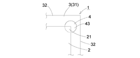
- the glass film laminated body (1) based on this invention consists of a glass film (2) and a support body (3), and on a support body (3), a peeling start part ( 4) is provided.
- the material of the glass film (2) silicate glass is used, preferably silica glass or borosilicate glass is used, and most preferably non-alkali glass is used.
- silicate glass is used, preferably silica glass or borosilicate glass is used, and most preferably non-alkali glass is used.
- the alkali-free glass is a glass that does not substantially contain an alkali component (alkali metal oxide), and specifically, a glass having a weight ratio of the alkali component of 1000 ppm or less. It is.
- the weight ratio of the alkali component in the present invention is preferably 500 ppm or less, more preferably 300 ppm or less.
- the thickness of the glass film (2) is preferably 300 ⁇ m or less, more preferably 5 ⁇ m to 200 ⁇ m, and most preferably 5 ⁇ m to 100 ⁇ m. Even if it is an ultra-thin plate glass having a thickness of 300 ⁇ m or less that is likely to be cracked or chipped at the corner, it can be easily peeled off from the support. In addition, it is possible to easily perform manufacturing-related processing on the glass film (2) that is difficult to handle and that is likely to cause problems such as mispositioning and displacement during patterning. When the thickness is less than 5 ⁇ m, the strength of the glass film (2) tends to be insufficient, and the glass film (2) is peeled off from the glass film laminate (1) and is easily damaged when incorporated into a device.
- the support (3) is for supporting the glass film (2) and protrudes beyond the glass film (2) in order to protect the end of the glass film (2).
- the protruding amount of the support (3) is preferably 5 mm to 20 mm. If the protruding amount of the support (3) is less than 5 mm, the support (3) may be difficult to produce the peeling start part (4) by separating from the end (32). On the other hand, when the protrusion amount of the support (3) exceeds 20 mm, the area of the glass film (2) occupying the support (3) is decreased, which may deteriorate the production efficiency.
- the material thereof is not particularly limited, and a synthetic resin plate, a natural resin plate, a wooden plate, a metal plate, a glass plate, a ceramic plate, or the like is used. be able to. Moreover, it does not specifically limit about the thickness of a support body (3).
- a support body (3) When the support (3) is required to have rigidity, a thick resin plate, glass plate, or the like can be used.
- the support (3) is not required to have rigidity, and a resin film such as a PET film can be used for the purpose of improving the handling of the glass film (2).
- support glass (31) for the support (3).
- the supporting glass (31) it is preferable to use a glass having a difference in thermal expansion coefficient at 30 to 380 ° C. from that of the glass film (2) within 5 ⁇ 10 ⁇ 7 / ° C.
- silicate glass, silica glass, borosilicate glass, non-alkali glass and the like are used as in the glass film (2). More preferably, the supporting glass (31) and the glass film (2) use the same glass.
- the thickness of the supporting glass (31) is preferably 400 ⁇ m or more. This is because if the thickness of the supporting glass (31) is less than 400 ⁇ m, a problem may occur in terms of strength when the supporting glass is handled alone.
- the thickness of the supporting glass (31) is preferably 400 ⁇ m to 700 ⁇ m, and most preferably 500 ⁇ m to 700 ⁇ m. This makes it possible to reliably support the glass film (2) and to effectively suppress breakage that may occur when the glass film (2) and the supporting glass (31) are peeled off. .
- the surface roughness Ra of the glass film (2) and the supporting glass (31) on the side in contact with each other is 2.0 nm or less.
- the glass film (2) and the supporting glass (31) are in contact with each other on a smooth surface, so that the adhesion is good, and the glass film and the supporting glass are firmly and stably laminated without using an adhesive. It becomes possible to make it.
- the surface roughness Ra of the surface of the glass film (2) and the supporting glass (3) is preferably 1.0 nm or less, more preferably 0.5 nm or less, and 0.2 nm or less. Is most preferred.
- the GI values of the surfaces of the glass film (2) and the supporting glass (31) on the side in contact with each other are 1000 pcs / m 2 or less.
- the GI value refers to the number (pcs) of impure particles having a major axis of 1 ⁇ m or more existing in a 1 m 2 region.
- GI value of the glass film (2) and the surface of the supporting glass (3) is more preferably each 500pcs / m 2 or less, and most preferably 100pcs / m 2 or less.
- the glass film (2) and support glass (31) used in the present invention are preferably formed by a downdraw method. This is because the surface of the glass film (2) can be formed more smoothly.
- the overflow downdraw method shown in FIG. 2 is a molding method in which both surfaces of the glass plate do not come into contact with the molded member at the time of molding, and the both surfaces (translucent surface) of the obtained glass plate are hardly scratched and polished. Even if not, high surface quality can be obtained. Thereby, it becomes possible to laminate
- the glass ribbon (G) immediately after flowing down from the lower end portion (71) of the wedge-shaped molded body (7) is stretched downward while the shrinkage in the width direction is regulated by the cooling roller (8) to have a predetermined thickness. Until it gets thinner. Next, the glass ribbon (G) having reached the predetermined thickness is gradually cooled in a slow cooling furnace (annealer), the thermal distortion of the glass ribbon (G) is removed, and the glass ribbon (G) is cut into a predetermined dimension. Thereby, the glass sheet used as a glass film (2) or support glass (31) is shape
- the peeling start part (4) is provided on the support (3) so as to be separated from the end side (32). As a result, the support (3) can be projected and laminated more than the glass film (2), and the corner portion (21) of the glass film (2) is exposed on the peeling start portion (4). It can be laminated.
- the peeling start portion (4) is preferably provided in the vicinity of the four corners of the support (3).
- peeling start part (4) is provided in one corner part (21) of the glass film (2) in FIG. 1, it may be provided in two or more corner parts (21).
- the shape of the peeling start part (4) is preferably circular in plan view as shown in FIG.
- the shape of the peeling start portion (4) is not limited to the circular shape shown in FIG. 3 (a), and may be rectangular in plan view as shown in FIG. 3 (b).
- the rectangular peeling start portion (4) can be produced by sandblasting, etching, or the like.
- a resin material such as PET having toughness is used for the support (3), it can be easily formed into a rectangular shape by punching as shown in FIG. 3 (b).
- the method for producing the peeling start portion (4) is not particularly limited, and may be formed by processing the support (3) after forming the support (3) as described above. At the time of molding, the peeling start part (4) may be produced simultaneously.
- the peeling start part (4) is preferably circular with a diameter of 1 to 30 mm. Thereby, the influence with respect to a support body (3) by having provided the peeling start part (4) can be made small. If the diameter is smaller than 1 mm, it may be difficult to grip the glass film (2) when peeling the glass film (2) from the support (3). If the diameter is larger than 30 mm, There exists a possibility that the intensity
- Area glass film (2) is exposed from the release start portion (4) is preferably a 0.19 mm 2 ⁇ 400 mm 2. Thereby, the influence with respect to the glass film (2) by the glass film (2) being exposed from a support body (3) can be made small.
- the corner part (21) of the glass film (2) can be gripped when the glass film (2) is peeled off. May be difficult.
- the exposed area from the peeling start part (4) of a glass film (2) is larger than 400 mm ⁇ 2 >, the corner part (21) of a glass film (2) will bend in a peeling start part (4), and a glass film ( 2) may be damaged.
- the peeling start part (4) is preferably a through hole (41) provided on the support (3) so as to be separated from the end side (32), as shown in FIG. 4 (a).
- the corner portion (21) of the glass film (2) can be lifted, and it becomes easier to grip.
- the through hole (41) can be easily provided on the support (3) by a drill or the like.
- the peeling start part (4) can also be made into a depression hole (42) as shown in FIG.4 (b). By setting it as a depression hole (42), it can be made easy to convey a glass film laminated body (1) by the floating by air etc.
- the corner portion (21) of the glass film (2) is moved into the through hole (41). And the corner part (21) of the glass film (2) comes into contact with the conveying surface of the glass film laminate (1) through the through hole (41), and the glass film laminate (1) is conveyed.
- the glass film (2) may be broken inside.
- it is a depression hole (42)
- the corner part (21) of a glass film (2) will be on a conveyance surface. The glass film laminate (1) can be transported more safely without contact.
- the glass film (2) and the support (3) may be laminated with an adhesive layer (5) interposed therebetween. Since the glass film (2) is peeled at the end, it is preferable to use a slightly sticky adhesive for the adhesive layer (5).
- the adhesive strength is 0.002 to 2.00 N. / 25 mm is preferable, 0.005 to 1.00 N / 25 mm is more preferable, and 0.01 to 0.7 N / 25 mm is most preferable.
- the glass film laminate (1) according to the present invention is subjected to manufacturing-related processing such as film formation, washing, and patterning, and then the glass film (2) is peeled from the peeling start portion (4).
- manufacturing-related processing such as film formation, washing, and patterning
- the corner (21) of the glass film (2) is used by using a finger or a gripping tool such as tweezers from the gap (43) between the glass film (2) and the peeling start part (4).
- the glass film (2) is peeled off from the support (3) by peeling off the glass film (2) from the support (3).
- a resin film such as a PET film is inserted between the glass film (2) and the support (3) from the gap (43), and the glass film (2) is gradually formed starting from the corner (21).
- the glass film (2) and the support (3) may be peeled off by floating.
- the corner ((2) of the glass film (2) can be easily bent by bending the support (3) in the vicinity of the peeling start portion (4). 21) can be gripped.
- the glass film (2) after peeling is incorporated into an electronic device or the like for each use (for example, as a glass substrate of an electronic device).
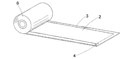
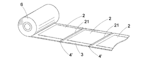
- FIG. 5 and 6 are other embodiments of the glass film laminate (1) according to the present invention.
- FIG. 5 shows that a glass film (2) is intermittently laminated for each predetermined length on a support (3) made of a long resin film (PET film or the like). ) Is wound to form a roll body (6). Thereby, the transport efficiency of a glass film laminated body (1) can be improved. Furthermore, by using a roll-to-roll process, it is possible to improve the efficiency of manufacturing-related processing.
- At least one corner portion (21) of each glass film (2) is provided with a peeling start portion (4). As shown in FIG. 6, the glass film (2) may be continuously laminated on the support (3).
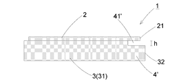
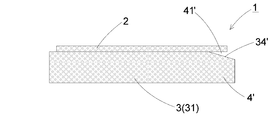
- the glass film laminated body (1) based on this invention consists of a glass film (2) and a support body (3), and includes the edge (32) of a support body (3).
- a thin portion (4 ′) is provided at the end side portion.
- the support (3) is for supporting the glass film (2) and protrudes beyond the glass film (2) in order to protect the end of the glass film (2).
- the amount of protrusion of the support (3) is preferably 1 mm to 20 mm. If the amount of protrusion of the support (3) is less than 1 mm, it may be difficult to produce a thin portion (4 ') at the end of the support (3). On the other hand, when the protrusion amount of the support (3) exceeds 20 mm, the area of the glass film (2) occupying the support (3) is decreased, which may deteriorate the production efficiency.
- the thin-walled portion (4 ') is provided on the end side portion including the end side (32) of the support (3) in a state where the surface on the glass film (2) side is partially cut. Thereby, at least one part of the edge part (21) of a glass film (2) will space apart from a support body (3) through a clearance gap (41 ') on a thin part (4'). Therefore, the edge (21) of the glass film (2) spaced apart from the thin part (4 ′) can be easily gripped, and the glass film (2) is damaged when the glass film (2) is peeled off. Can be effectively prevented. Furthermore, since only the surface on the glass film (2) side is partially cut off, the thin-walled portion (4 ′) has a glass film (outward from the end (32) of the support (3). The glass film (2) can be appropriately protected without exposing 2).
- the thin-walled portion (4 ') is preferably provided so that at least one corner portion (22) of the glass film (2) is separated from the support (3). Thereby, the corner part (22) of a glass film (2) can be easily hold
- the thin-walled portion (4 ′) is preferably provided at the corner portion (33) of the support (3).
- the thin part (4 ') is provided so that one corner part (22) of a glass film (2) may space apart, it is not limited to this, A thin part (4' ) May be provided at corners (33) of the support (3) at two or more locations.
- the shape of the thin wall portion (4 ') is not particularly limited as long as the corner portion (22) of the glass film (2) can be provided so as to be separated.
- the thin portion (4 ') may be formed by providing a step as shown in FIG. Further, as shown in FIG. 8B, it is preferably formed by providing an inclined portion (34 ') that inclines so as to approach the end side (32).
- the inclined portion (34 Since ') serves as a guide for guiding the peeling sheet, it becomes easy to insert the peeling sheet.
- the method for forming the thin portion (4 ') is not particularly limited, but it can be formed by polishing, grinding, sand blasting, etching or the like.
- the thin portion (4 ') can be formed by pressing.
- the thin part (4 ′) may be formed by processing the support (3).
- the thin part (4 ′) is formed. You may form simultaneously.
- a second support member (36) that is slightly smaller than the first support member (35) is laminated and fixed on the first support member (35).
- the support (3) may be used to produce the thin portion (4 ′).
- the first support body (35) is slightly larger than the glass film (2) and the second support body (36) is slightly smaller than the glass film (2). Thereby, a clearance gap (41 ') can be easily provided along the circumference
- the thin part (4 ') is preferably separated from the support (3) by a width of 0.5 to 15 mm from the end (21) of the glass film (2).
- reducing influences such as drooping of the glass film (2) by the glass film (2) being spaced apart from a support body (3).
- the separation width between the glass film (2) and the support (3) exceeds 15 mm, the glass film (2) may come into contact with the thin portion (4 '). More preferably, the thin portion (4 ') is spaced from the support (3) with a width of 1 to 10 mm from the end (21) of the glass film (2).
- the spacing h between the glass film (2) and the support (3) in the thin part (4 ') is preferably 0.01 mm or more. Thereby, by inserting a peeling sheet such as a resin film from the gap (41 ′) between the support (3) and the glass film (2) present on the thin wall portion (4 ′), the glass film (2) And the support (3) can be easily peeled off. If the separation interval h in the thin wall portion (4 ') is less than 0.01 mm, the glass film (2) may be difficult to grip.
- the separation interval h is preferably larger than the thickness of a peeling sheet such as a resin film used when peeling the glass film (2).
- the separation interval h in the thin portion (4 ′) is preferably 1/2 or less of the thickness of the support (3) to be used, and 1/3 The following is more preferable.
- the glass film (2) and the support (3) may be laminated with an adhesive layer (5) interposed therebetween. Since the glass film (2) is peeled at the end, it is preferable to use a slightly sticky adhesive for the adhesive layer (5).
- the adhesive strength is 0.002 to 2.00 N. / 25 mm is preferable, 0.005 to 1.00 N / 25 mm is more preferable, and 0.01 to 0.7 N / 25 mm is most preferable.
- the glass film laminate (1) according to the present invention is subjected to manufacturing-related processing such as film formation, washing, and patterning, and then the glass film (2) is peeled off from the thin wall portion (4 ').
- manufacturing-related processing such as film formation, washing, and patterning
- the glass film (2) is peeled off from the thin wall portion (4 ').
- a finger or a gripping tool such as tweezers from the gap (41 ′) between the glass film (2) and the thin wall portion (4 ′)
- the corner portion (22 ) And the glass film (2) is peeled off from the support (3) to peel the glass film (2) from the support (3).
- a release sheet such as a resin film such as a PET film is inserted between the glass film (2) and the support (3) through the gap (41 ′), and gradually starts from the corner (22).
- the glass film (2) and the support (3) may be separated by floating the glass film (2).
- the support (3) in the vicinity of the thin-walled portion (4 ') can be easily bent by bending it to the opposite side of the glass film (2).
- the corner part (22) of the glass film (2) can be gripped.
- the glass film (2) after peeling is incorporated into an electronic device or the like for each use (for example, as a glass substrate of an electronic device).
- FIG. 10 and 11 are other embodiments of the glass film laminate (1) according to the present invention.
- a glass film (2) is intermittently laminated for each predetermined length on a support (3) made of a long resin film (PET film or the like). ) Is wound to form a roll body (6).
- PET film or the like a long resin film
- a thin portion (4 ') is provided immediately below at least one end (21) of each glass film (2).
- the glass film (2) is continuously laminated
- the present invention can be suitably used when a glass substrate used for a flat panel display such as a liquid crystal display or an organic EL display, a device such as a solar cell, or a cover glass for organic EL lighting.
Abstract
Description
2 ガラスフィルム
3 支持体
31 支持ガラス
32 端辺
32 貫通孔
4 剥離開始部
4‘ 薄肉部
5 接着剤層
6 ロール体
DESCRIPTION OF
Claims (12)
- 支持体にガラスフィルムを積層したガラスフィルム積層体であって、
前記支持体は、前記ガラスフィルムから食み出しており、
前記支持体には、前記ガラスフィルムの少なくとも1つのコーナー部を前記支持体から露出させる剥離開始部が、前記支持体の端辺から離間して設けられていることを特徴とするガラスフィルム積層体。 A glass film laminate in which a glass film is laminated on a support,
The support is protruding from the glass film,
The glass film laminate, wherein the support is provided with a peeling start portion for exposing at least one corner portion of the glass film from the support so as to be separated from an end side of the support. . - 前記剥離開始部は、直径1~30mmの円形であることを特徴とする請求項1に記載のガラスフィルム積層体。 The glass film laminate according to claim 1, wherein the peeling start portion is a circle having a diameter of 1 to 30 mm.
- 前記ガラスフィルムが前記剥離開始部に露出している面積が、0.19mm2~400mm2であることを特徴とする請求項1または2に記載のガラスフィルム積層体。 The glass film laminate according to claim 1 or 2, wherein an area of the glass film exposed to the peeling start part is 0.19 mm 2 to 400 mm 2 .
- 前記剥離開始部は、貫通孔であることを特徴とする請求項1~3のいずれかに記載のガラスフィルム積層体。 The glass film laminate according to any one of claims 1 to 3, wherein the peeling start portion is a through hole.
- 支持体にガラスフィルムを積層したガラスフィルム積層体であって、
前記支持体は、前記ガラスフィルムから食み出しており、
前記支持体の端辺部には、肉厚が部分的に小さい薄肉部が設けられ、
前記ガラスフィルムの端辺の少なくとも一部が、前記薄肉部上で、前記支持体から離間していることを特徴とするガラスフィルム積層体。 A glass film laminate in which a glass film is laminated on a support,
The support is protruding from the glass film,
The end portion of the support is provided with a thin portion with a small thickness.
At least a part of the edge of the glass film is spaced apart from the support on the thin wall portion. - 前記薄肉部は、前記ガラスフィルムの少なくとも1箇所のコーナー部が前記支持体から離間するように設けられていることを特徴とする請求項5に記載のガラスフィルム積層体。 6. The glass film laminate according to claim 5, wherein the thin portion is provided such that at least one corner portion of the glass film is separated from the support.
- 前記ガラスフィルムは、前記ガラスフィルムの端辺から0.5~15mmの幅で前記支持体と離間していることを特徴とする請求項5又は6に記載のガラスフィルム積層体。 The glass film laminate according to claim 5 or 6, wherein the glass film is spaced from the support with a width of 0.5 to 15 mm from an edge of the glass film.
- 前記ガラスフィルムと前記支持体との前記薄肉部における離間間隔は、0.01mm以上であることを特徴とする請求項5~7の何れかに記載のガラスフィルム積層体。 The glass film laminate according to any one of claims 5 to 7, wherein a distance between the thin portions of the glass film and the support is 0.01 mm or more.
- 前記支持体は、支持ガラスであることを特徴とする請求項1~8のいずれかに記載のガラスフィルム積層体。 The glass film laminate according to any one of claims 1 to 8, wherein the support is support glass.
- 前記ガラスフィルム及び前記支持ガラスの相互に接触する側の表面の表面粗さRaが夫々2.0nm以下であることを特徴とする請求項9に記載のガラスフィルム積層体。 10. The glass film laminate according to claim 9, wherein the surface roughness Ra of the surfaces of the glass film and the supporting glass that are in contact with each other is 2.0 nm or less.
- 前記ガラスフィルム、及び前記支持ガラスは、それぞれオーバーフローダウンドロー法によって成形されていることを特徴とする請求項9又は10に記載のガラスフィルム積層体。 The glass film laminate according to claim 9 or 10, wherein the glass film and the support glass are each formed by an overflow down draw method.
- 前記ガラスフィルムの厚みは、300μm以下であることを特徴とする請求項1~11のいずれかに記載のガラスフィルム積層体。 The glass film laminate according to any one of claims 1 to 11, wherein the glass film has a thickness of 300 µm or less.
Priority Applications (3)
| Application Number | Priority Date | Filing Date | Title |
|---|---|---|---|
| EP11812548.3A EP2511092B1 (en) | 2010-07-28 | 2011-07-28 | Glass film laminate |
| KR1020127020275A KR101804195B1 (en) | 2010-07-28 | 2011-07-28 | Glass film laminate |
| CN201180010413.2A CN102770268B (en) | 2010-07-28 | 2011-07-28 | Glass film laminate |
Applications Claiming Priority (4)
| Application Number | Priority Date | Filing Date | Title |
|---|---|---|---|
| JP2010169853A JP5585937B2 (en) | 2010-07-28 | 2010-07-28 | Glass film laminate |
| JP2010-169853 | 2010-07-28 | ||
| JP2010285246A JP5692513B2 (en) | 2010-12-22 | 2010-12-22 | Glass film laminate |
| JP2010-285246 | 2010-12-22 |
Publications (1)
| Publication Number | Publication Date |
|---|---|
| WO2012014959A1 true WO2012014959A1 (en) | 2012-02-02 |
Family
ID=45530161
Family Applications (1)
| Application Number | Title | Priority Date | Filing Date |
|---|---|---|---|
| PCT/JP2011/067215 WO2012014959A1 (en) | 2010-07-28 | 2011-07-28 | Glass film laminate |
Country Status (6)
| Country | Link |
|---|---|
| US (1) | US9333724B2 (en) |
| EP (2) | EP2703156B1 (en) |
| KR (1) | KR101804195B1 (en) |
| CN (1) | CN102770268B (en) |
| TW (1) | TWI527699B (en) |
| WO (1) | WO2012014959A1 (en) |
Cited By (3)
| Publication number | Priority date | Publication date | Assignee | Title |
|---|---|---|---|---|
| WO2014133007A1 (en) * | 2013-02-26 | 2014-09-04 | 日本電気硝子株式会社 | Method for manufacturing electronic device |
| JP2014231222A (en) * | 2013-04-30 | 2014-12-11 | 日本電気硝子株式会社 | Glass film laminate and method of producing electronic device |
| WO2015190418A1 (en) * | 2014-06-13 | 2015-12-17 | 日本電気硝子株式会社 | Method for manufacturing glass film, and method for manufacturing electronic device including glass film |
Families Citing this family (22)
| Publication number | Priority date | Publication date | Assignee | Title |
|---|---|---|---|---|
| US20140054348A1 (en) * | 2011-06-08 | 2014-02-27 | Yasuo Teranishi | Method for cutting plate-like glass, and cutting device therefor |
| JP5849492B2 (en) * | 2011-07-25 | 2016-01-27 | 大日本印刷株式会社 | Method for producing glass film laminate |
| DE102011084129A1 (en) * | 2011-10-07 | 2013-04-11 | Schott Ag | Glass foil with specially designed edge |
| JP6086773B2 (en) | 2013-03-21 | 2017-03-01 | 日東電工株式会社 | Thin glass long body |
| KR20150001006A (en) | 2013-06-26 | 2015-01-06 | 삼성디스플레이 주식회사 | Glass film laminate, method of manufacturing the same, and method of manufacturing glass film |
| CN103435257B (en) * | 2013-08-09 | 2016-04-27 | 刘国正 | Glass film layers lamination and manufacture method thereof |
| TWI481578B (en) * | 2013-12-20 | 2015-04-21 | Ind Tech Res Inst | Interleaving element for a roll of glass substrate |
| WO2015112958A1 (en) | 2014-01-27 | 2015-07-30 | Corning Incorporated | Articles and methods for controlled bonding of thin sheets with carriers |
| WO2015152158A1 (en) | 2014-03-31 | 2015-10-08 | 株式会社Joled | Laminate, method for separating laminate and method for manufacturing flexible device |
| SG11201608442TA (en) | 2014-04-09 | 2016-11-29 | Corning Inc | Device modified substrate article and methods for making |
| DE112014005031B4 (en) * | 2014-11-13 | 2019-04-25 | Shindengen Electric Manufacturing Co., Ltd. | Method for producing a semiconductor device and device for producing a glass layer |
| JP2018500263A (en) * | 2014-11-26 | 2018-01-11 | コーニング インコーポレイテッド | Thin glass sheet and system and method for forming the same |
| WO2016187186A1 (en) | 2015-05-19 | 2016-11-24 | Corning Incorporated | Articles and methods for bonding sheets with carriers |
| US11905201B2 (en) | 2015-06-26 | 2024-02-20 | Corning Incorporated | Methods and articles including a sheet and a carrier |
| DE102016218176A1 (en) * | 2015-10-02 | 2017-04-06 | Schott Ag | Long-term flexible glass material, as well as method for producing a long-term flexible glass material |
| TW201737766A (en) * | 2016-01-21 | 2017-10-16 | 康寧公司 | Methods for processing a substrate |
| CN105979029A (en) * | 2016-04-27 | 2016-09-28 | 努比亚技术有限公司 | Terminal |
| TW201825623A (en) | 2016-08-30 | 2018-07-16 | 美商康寧公司 | Siloxane plasma polymers for sheet bonding |
| TWI821867B (en) | 2016-08-31 | 2023-11-11 | 美商康寧公司 | Articles of controllably bonded sheets and methods for making same |
| JP6815159B2 (en) * | 2016-10-14 | 2021-01-20 | 株式会社ジャパンディスプレイ | Display device |
| WO2019118660A1 (en) | 2017-12-15 | 2019-06-20 | Corning Incorporated | Method for treating a substrate and method for making articles comprising bonded sheets |
| CN108657628B (en) * | 2018-04-03 | 2020-06-19 | 友达光电(厦门)有限公司 | Protective film and tearing method thereof |
Citations (3)
| Publication number | Priority date | Publication date | Assignee | Title |
|---|---|---|---|---|
| JPH0886993A (en) | 1994-07-18 | 1996-04-02 | Sharp Corp | Jig for transporting substrate and production of liquid crystal display element by using the same |
| JP2008133174A (en) | 2006-10-24 | 2008-06-12 | Nippon Electric Glass Co Ltd | Glass ribbon producing apparatus and process for producing the same |
| JP2010018505A (en) | 2008-07-14 | 2010-01-28 | Asahi Glass Co Ltd | Glass laminate, panel for display device with supporting body, panel for display device, display device, and methods for manufacturing them |
Family Cites Families (8)
| Publication number | Priority date | Publication date | Assignee | Title |
|---|---|---|---|---|
| WO2003051783A1 (en) * | 2001-12-14 | 2003-06-26 | Corning Incorporated | Apparatus and method for making sheet glass by the overflow downdraw fusion process |
| KR20090006824A (en) * | 2006-05-08 | 2009-01-15 | 아사히 가라스 가부시키가이샤 | Thin-sheet glass laminate, process for manufacturing display apparatus using the laminate, and supporting glass substrate |
| JP4885675B2 (en) | 2006-09-27 | 2012-02-29 | 株式会社Nsc | Method for cutting and separating laminated glass plates |
| EP2077254B1 (en) | 2006-10-24 | 2013-06-05 | Nippon Electric Glass Co., Ltd. | Glass ribbon producing apparatus and process for producing the same |
| JP5691148B2 (en) * | 2008-10-01 | 2015-04-01 | 日本電気硝子株式会社 | Glass roll, glass roll manufacturing apparatus, and glass roll manufacturing method |
| JP5594522B2 (en) * | 2009-07-03 | 2014-09-24 | 日本電気硝子株式会社 | Glass film laminate for manufacturing electronic devices |
| JP5510901B2 (en) | 2009-09-18 | 2014-06-04 | 日本電気硝子株式会社 | GLASS FILM MANUFACTURING METHOD, GLASS FILM PROCESSING METHOD, AND GLASS FILM LAMINATE |
| WO2011086991A1 (en) * | 2010-01-12 | 2011-07-21 | 日本電気硝子株式会社 | Glass film laminate and process for production thereof, and process for production of glass film |
-
2011
- 2011-07-28 EP EP13191656.1A patent/EP2703156B1/en not_active Not-in-force
- 2011-07-28 TW TW100126794A patent/TWI527699B/en not_active IP Right Cessation
- 2011-07-28 US US13/192,639 patent/US9333724B2/en active Active
- 2011-07-28 KR KR1020127020275A patent/KR101804195B1/en active IP Right Grant
- 2011-07-28 EP EP11812548.3A patent/EP2511092B1/en not_active Not-in-force
- 2011-07-28 CN CN201180010413.2A patent/CN102770268B/en not_active Expired - Fee Related
- 2011-07-28 WO PCT/JP2011/067215 patent/WO2012014959A1/en active Application Filing
Patent Citations (3)
| Publication number | Priority date | Publication date | Assignee | Title |
|---|---|---|---|---|
| JPH0886993A (en) | 1994-07-18 | 1996-04-02 | Sharp Corp | Jig for transporting substrate and production of liquid crystal display element by using the same |
| JP2008133174A (en) | 2006-10-24 | 2008-06-12 | Nippon Electric Glass Co Ltd | Glass ribbon producing apparatus and process for producing the same |
| JP2010018505A (en) | 2008-07-14 | 2010-01-28 | Asahi Glass Co Ltd | Glass laminate, panel for display device with supporting body, panel for display device, display device, and methods for manufacturing them |
Non-Patent Citations (1)
| Title |
|---|
| See also references of EP2511092A4 |
Cited By (5)
| Publication number | Priority date | Publication date | Assignee | Title |
|---|---|---|---|---|
| WO2014133007A1 (en) * | 2013-02-26 | 2014-09-04 | 日本電気硝子株式会社 | Method for manufacturing electronic device |
| JP2014194541A (en) * | 2013-02-26 | 2014-10-09 | Nippon Electric Glass Co Ltd | Manufacturing method of electronic device |
| JP2014231222A (en) * | 2013-04-30 | 2014-12-11 | 日本電気硝子株式会社 | Glass film laminate and method of producing electronic device |
| WO2015190418A1 (en) * | 2014-06-13 | 2015-12-17 | 日本電気硝子株式会社 | Method for manufacturing glass film, and method for manufacturing electronic device including glass film |
| JP2016003147A (en) * | 2014-06-13 | 2016-01-12 | 日本電気硝子株式会社 | Manufacturing method of glass film, and manufacturing method of electronic device including glass film |
Also Published As
| Publication number | Publication date |
|---|---|
| EP2511092A1 (en) | 2012-10-17 |
| TWI527699B (en) | 2016-04-01 |
| EP2511092B1 (en) | 2015-01-28 |
| CN102770268B (en) | 2016-05-11 |
| KR101804195B1 (en) | 2017-12-04 |
| US20120135187A1 (en) | 2012-05-31 |
| EP2703156A1 (en) | 2014-03-05 |
| TW201204555A (en) | 2012-02-01 |
| EP2703156B1 (en) | 2015-01-14 |
| US9333724B2 (en) | 2016-05-10 |
| KR20130086113A (en) | 2013-07-31 |
| EP2511092A4 (en) | 2013-05-08 |
| CN102770268A (en) | 2012-11-07 |
Similar Documents
| Publication | Publication Date | Title |
|---|---|---|
| WO2012014959A1 (en) | Glass film laminate | |
| JP5692513B2 (en) | Glass film laminate | |
| JP5794325B2 (en) | Manufacturing method of glass substrate for electronic device and manufacturing method of cover glass for electronic device | |
| JP5645123B2 (en) | Glass film laminate, method for producing the same, and method for producing glass film | |
| JP5510880B2 (en) | Glass film laminate, glass roll of the laminate, and method for producing glass roll | |
| US20170072675A1 (en) | Method for producing glass film, method for treating glass film and glass film laminate | |
| JP2011121320A (en) | Glass film laminate, glass roll thereof, and method for manufacturing glass roll | |
| JP5585937B2 (en) | Glass film laminate | |
| WO2015012268A1 (en) | Glass film manufacturing method, and glass film peeling method | |
| JP2010215436A (en) | Glass film laminate | |
| WO2014178405A1 (en) | Glass film laminate, and production method for electronic device | |
| JP6327580B2 (en) | Glass film laminate and method for producing electronic device |
Legal Events
| Date | Code | Title | Description |
|---|---|---|---|
| WWE | Wipo information: entry into national phase |
Ref document number: 201180010413.2 Country of ref document: CN |
|
| 121 | Ep: the epo has been informed by wipo that ep was designated in this application |
Ref document number: 11812548 Country of ref document: EP Kind code of ref document: A1 |
|
| WWE | Wipo information: entry into national phase |
Ref document number: 2011812548 Country of ref document: EP |
|
| ENP | Entry into the national phase |
Ref document number: 20127020275 Country of ref document: KR Kind code of ref document: A |
|
| NENP | Non-entry into the national phase |
Ref country code: DE |