WO2012014403A1 - 空間における変化領域検出装置及び方法 - Google Patents
空間における変化領域検出装置及び方法 Download PDFInfo
- Publication number
- WO2012014403A1 WO2012014403A1 PCT/JP2011/004029 JP2011004029W WO2012014403A1 WO 2012014403 A1 WO2012014403 A1 WO 2012014403A1 JP 2011004029 W JP2011004029 W JP 2011004029W WO 2012014403 A1 WO2012014403 A1 WO 2012014403A1
- Authority
- WO
- WIPO (PCT)
- Prior art keywords
- feature point
- image
- feature
- reference image
- captured image
- Prior art date
- Legal status (The legal status is an assumption and is not a legal conclusion. Google has not performed a legal analysis and makes no representation as to the accuracy of the status listed.)
- Ceased
Links
Images

Classifications
-
- G—PHYSICS
- G06—COMPUTING OR CALCULATING; COUNTING
- G06V—IMAGE OR VIDEO RECOGNITION OR UNDERSTANDING
- G06V10/00—Arrangements for image or video recognition or understanding
- G06V10/70—Arrangements for image or video recognition or understanding using pattern recognition or machine learning
- G06V10/74—Image or video pattern matching; Proximity measures in feature spaces
- G06V10/75—Organisation of the matching processes, e.g. simultaneous or sequential comparisons of image or video features; Coarse-fine approaches, e.g. multi-scale approaches; using context analysis; Selection of dictionaries
- G06V10/757—Matching configurations of points or features
-
- G—PHYSICS
- G06—COMPUTING OR CALCULATING; COUNTING
- G06T—IMAGE DATA PROCESSING OR GENERATION, IN GENERAL
- G06T7/00—Image analysis
- G06T7/20—Analysis of motion
- G06T7/246—Analysis of motion using feature-based methods, e.g. the tracking of corners or segments
-
- G—PHYSICS
- G06—COMPUTING OR CALCULATING; COUNTING
- G06V—IMAGE OR VIDEO RECOGNITION OR UNDERSTANDING
- G06V10/00—Arrangements for image or video recognition or understanding
- G06V10/40—Extraction of image or video features
- G06V10/46—Descriptors for shape, contour or point-related descriptors, e.g. scale invariant feature transform [SIFT] or bags of words [BoW]; Salient regional features
- G06V10/462—Salient features, e.g. scale invariant feature transforms [SIFT]
-
- G—PHYSICS
- G06—COMPUTING OR CALCULATING; COUNTING
- G06T—IMAGE DATA PROCESSING OR GENERATION, IN GENERAL
- G06T2207/00—Indexing scheme for image analysis or image enhancement
- G06T2207/30—Subject of image; Context of image processing
- G06T2207/30232—Surveillance
Definitions
- the present invention relates to an apparatus and method for detecting a change area in space from an image captured by a movable camera.
- One of the monitoring systems is to detect removal and leaving of articles based on an image of a wearable camera attached to a security guard.
- the removal of an item is realized by detecting an item that is present in the registered image but not in the captured image.
- the removal of an item for example, the placement of a dangerous item such as a bomb
- the image captured by the wearable camera changes in accordance with the position, orientation, and the like of the wearable camera, information (positioning information) indicating which space is being imaged is required. That is, in the wearable camera, sensors such as a GPS, a gyro sensor, and a magnetic direction sensor are mounted, and positioning information as attribute information of a captured image is acquired by this sensor. Then, an image corresponding to the positioning information (hereinafter, this image is referred to as a reference image) is selected from the registered images. That is, the reference image which image
- a reference image which image
- Patent Document 1 As for alignment using image processing, there is a technique described in, for example, Patent Document 1.
- Patent Document 1 selects a reference image in the same space as the captured image under the premise that the captured image originally includes a change region changing with respect to the reference image. Not intended. That is, in the conventional image processing represented by Patent Document 1, it is not considered that a part of the captured image is changed from the reference image, so the pattern matching of the reference image in the same space as the reference image is performed. If it is attempted to select by the method, it may not be possible to select an appropriate reference image. In particular, since the technique described in Patent Document 1 performs pattern matching between local features, it is susceptible to the change area of the captured image, and as a result, the possibility of selecting an incorrect reference image Is considered high.
- positioning sensors such as GPS have the disadvantage that the usable location is limited. In the case of GPS, it can only be used outdoors. In addition to GPS, there is a positioning method using UWB, but in this case, it is necessary to install a receiver in the facility, which complicates the system. In any case, when the alignment between the captured image and the reference image is performed using the sensor, the usable location is limited as compared with the case where the alignment is performed by image processing, and / or the camera is used. Besides, there is a disadvantage that a complicated configuration is required.
- An object of the present invention is to provide a detection apparatus and method capable of accurately detecting a change area in space without using a positioning sensor.
- a feature point detection unit for detecting feature points of a captured image, a registered image database for storing a plurality of registered images, and reference from among the feature points of the captured image
- a first feature point selection unit for selecting feature points used to determine an image, a feature point selected by the first feature point selection unit, and a feature point of each registered image stored in the registration database
- a reference image determining unit that determines an image having the highest degree of matching with the captured image among the plurality of registered images by performing matching determination between the captured image and each registered image
- a second feature point selection unit for selecting a feature point used to calculate a geometric transformation parameter from feature points of the captured image and feature points of the reference image; and the second feature point selection unit
- a geometric conversion parameter calculation unit that calculates a geometric conversion parameter using the selected feature points, and from among the feature points of the captured image and the feature points of the reference image, the captured image and the reference image
- One aspect of the change area detection method is a change area detection method of calculating the degree of similarity between a captured image and a reference image, and detecting a change area in the captured image based on the similarity.
- a first feature point selecting step of selecting a feature point used to determine the reference image from feature points of the captured image, and a feature point of the captured image and a feature point of the reference image A second feature point selecting step of selecting a feature point used to calculate a geometric transformation parameter; and the feature image of the feature image and the feature image of the reference image, the feature image and the reference image.
- feature point selection suitable for determining a reference image feature point selection suitable for calculating a geometric transformation parameter, and feature point selection suitable for calculating a degree of similarity are performed independently. Therefore, it is possible to obtain an accurate reference image, an accurate geometric transformation parameter, and an accurate similarity without performing unnecessary calculations. As a result, the change area can be accurately determined with a small amount of calculation.
- Block diagram showing the configuration of the change area detection device according to the embodiment of the present invention 2A shows a tree structure of SR-tree, and FIG. 2B shows a data structure of leaves.
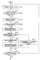
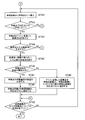
- Flow chart showing the processing procedure of the corresponding point search unit Diagram showing information stored in registered image database Flow chart showing processing procedure of reference image determination unit
- Flow chart showing the processing procedure of the similarity calculation unit Flow chart showing the processing procedure of the similarity calculation unit Diagram showing an image of the change area detection process of the change area detection device
- FIG. 1 shows the configuration of a change region detection apparatus according to an embodiment of the present invention.
- the change area detection apparatus 10 inputs the captured image S1 to the feature point detection unit 11.
- the captured image S1 is an image captured by a movable camera such as a wearable camera.
- the feature point detection unit 11 detects feature points of the captured image S1.
- the feature point is, for example, a point which becomes an extremum from a plurality of difference of gaussian (DOG) images generated from differences of different smoothed images as used in scale-invariant feature transform (SIFT). It may be detected.
- DOG difference of gaussian
- SIFT scale-invariant feature transform
- the feature point extraction by DOG is a known technique described in, for example, Non-Patent Document 1, and thus the description thereof is omitted here.
- the feature point detection unit 11 detects a plurality of feature points from one captured image.
- the detected feature point information S2 is sent to the feature amount calculating unit 12.
- the feature amount calculation unit 12 calculates a feature amount S3 for each feature point detected by the feature point detection unit 11, and outputs this.
- the feature quantity to be calculated is preferably, for example, a rotation and scale invariant feature quantity as used in SIFT.
- the feature amount is gradient information (multidimensional vector information) in the vicinity of the feature point.
- the corresponding point search feature point selection unit 13 selects a feature point to be used by the corresponding point search unit 14 from the feature points detected by the feature point detection unit 11. Specifically, among the feature points detected by the feature point detection unit 11, the corresponding point search feature point selection unit 13 selects only sparse feature points in the feature quantity space calculated by the feature quantity calculation unit 12. select. A sparse feature point is a feature point in which other feature points do not exist in the vicinity. The sparse feature points selected by the corresponding point search feature point selection unit 13 may be rephrased as being sparser than the feature points selected by the similarity calculation feature point selection unit 20 described later. .
- the corresponding point search unit 14 searches for feature points (corresponding points) of the registered image in which the distance between the feature amounts is equal to or less than the threshold value, for each of Nf feature points of the input image.
- the distance between feature quantities is the Euclidean distance.
- the corresponding points are searched based on the feature quantity index stored in the feature quantity index unit, instead of directly using the registered image. Thereby, the corresponding points can be searched more efficiently than directly using the registered image.
- the feature amount index unit 15 stores feature amounts at all feature points included in each registered image stored in the registered image database 17.
- the feature index unit 15 has an index structure such as SR-tree, for example, in order to streamline the search for corresponding points.
- the SR-tree is a known technique described in Patent Document 2 and the like, so the description thereof is omitted here.
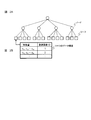
- the tree structure of SR-tree is shown in FIG. 2A, and the data structure of leaves is shown in FIG. 2B. As shown in FIG. 2B, in each entry of the leaf of the SR-tree, in addition to the feature amount, the identification number (ID) of the original registered image having the feature amount is also stored.
- ID the identification number
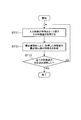
- FIG. 3 shows the processing procedure of the corresponding point search unit 14.
- the corresponding point search unit 14 searches for a plurality of corresponding points from the registered image per one feature point of the captured image. For example, the number of corresponding points of the registered image with respect to the p-th feature point of the captured image is Kp.
- the corresponding point search unit 14 selects one feature point of the input image (reference image) and acquires its feature amount.
- the nearest neighbor Kp feature points of the feature amount obtained in step ST11 are obtained as corresponding points of the registered image by the nearest neighbor search.
- step ST; NO If a negative result is obtained in step ST13 (step ST; NO), corresponding points for the next feature point are searched by repeating steps ST11 to ST12, and if a positive result (step ST; YES) is obtained in step ST13, The corresponding point search process ends.
- the feature index unit 15 is provided in the present embodiment, the corresponding points may be directly searched from the registered image.
- the reference image determination unit 16 uses the corresponding point information from the corresponding point search unit 14 and the registered image information from the registered image database 17 to correspond to the corresponding points searched by the corresponding point search unit 14. Vote 1 vote on the original registered image with points. The reference image determination unit 16 repeatedly performs this voting process on all corresponding points searched for all feature points of the input image (reference image). Then, the reference image determination unit 16 determines the registered image with the largest number of votes obtained as a reference image for the input image.
- the reference image determination unit 16 gives a weight according to the distance between the feature amounts calculated by the corresponding point search unit 14 and votes. In this way, since a vote result including the certainty of the corresponding points is obtained, a more accurate registered image is selected as a reference image.
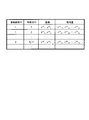
- the registered image database 17 stores the ID of the registered image, the ID of the feature point detected from the registered image, the coordinates of the feature point, and the feature amount of the feature point as one record. Further, the registered image database 17 has, for one registered image, a plurality of records for a plurality of feature points detected from the registered image.
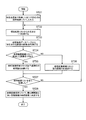
- FIG. 5 shows the processing procedure of the reference image determination unit 16.
- the reference image determination unit 16 puts all the corresponding points acquired in the corresponding point search in the search result list.
- the search result list is a list including feature point IDs of corresponding points and distances between feature points of the input image and feature amounts of the corresponding points.
- one corresponding point is acquired from the search result list.
- the image ID of the original image of the corresponding point is acquired from the registered image database 17.
- step ST24 it is determined whether the acquired image ID is present in the reference image candidate list.
- the reference image candidate list is a list including image IDs of registered images and the number of votes obtained. That is, it is a list of the number of votes obtained for each registered image. If an affirmative result is obtained in step ST24 (step ST24; YES), the process proceeds to step ST25, and the number of votes of the corresponding image ID of the reference image candidate list is added. On the other hand, if a negative result is obtained in step ST24 (step ST24; NO), the process proceeds to step ST26, and the corresponding image ID is added to the reference image candidate list.
- step ST27 it is determined whether all feature points included in the search result list have been processed. If an affirmative result is obtained in step ST27 (step ST27; YES), the process proceeds to step ST28, and the registered image with the largest number of votes obtained in the reference image candidate list is determined as the reference image. On the other hand, if a negative result is obtained in step ST27 (step ST27; NO), the process returns to step ST22.
- the geometric transformation parameter calculation feature point selection unit 18 selects a feature point serving as a reference used by the geometric transformation parameter calculation unit 19. Specifically, the feature point selecting unit for geometric transformation parameter calculation 18 selects the feature with the feature point of the reference image searched by the corresponding point searching unit 14 among the feature points of the input image detected by the feature point detecting unit 11 A fixed number of items are selected in order from the combination in which the amount distance is minimum. At this time, feature points closer than a certain distance in the coordinate space are not selected with respect to the feature points already selected.
- the geometric transformation parameter calculation feature point selection unit 18 selects a feature point having a predetermined degree or more of similarity between the feature point of the input image and the feature point of the reference image. Thereby, the accuracy of the correspondence between the input image and the reference image can be enhanced. Further, the geometric transformation parameter calculation feature point selection unit 18 selects a feature point having a distance in the coordinate space of a predetermined value or more between the feature point of the input image and the feature point of the reference image. This can increase the accuracy of geometric transformation.
- the geometric transformation parameter calculator 19 calculates a geometric transformation parameter that represents a geometric change from the input image to the reference image.
- the geometric transformation parameter calculation unit 19 prepares a plurality of sets of such reference points, using the feature points of the input image and the feature points of the reference image corresponding thereto as both reference points, and affine transformation parameters by the least square method.
- the set of reference points is the feature points selected by the geometric transformation parameter calculation feature point selection unit 18.
- the feature points of the input image having no feature point of the corresponding reference image are not included in the set of reference points. If there are at least three sets of reference points, it is possible to solve the affine transformation parameters by the least squares method.
- the inverse of the affine transformation is also calculated.
- the inverse transformation of the affine transformation is a geometric transformation from a reference image to an input image.
- the similarity calculation feature point selection unit 20 selects feature points of the input image and the reference image used by the similarity calculation unit 21. Specifically, the feature point selecting unit for similarity calculation 20 selects, among the feature points of the input image, a feature point whose feature amount distance from the feature point of the reference image searched in the corresponding point search is larger than a certain threshold. Do not select. In other words, among the feature points of the input image, the feature point calculating unit 21 uses only feature points whose feature amount distance with the feature point of the reference image searched in the corresponding point search is equal to or less than a certain threshold. Choose as. Also, the similarity calculation feature point selection unit 20 does not select a feature point closer than a certain distance in the already selected coordinate space. As a result, it is possible to exclude feature points of an area in which the image is not obviously changed or feature points densely packed in the coordinate space, thereby suppressing unnecessary calculation of similarity.
- the similarity calculation unit 21 calculates the distance between the feature amounts of corresponding feature points between the input image and the reference image, and sets this as the similarity. Specifically, the similarity calculation unit 21 first performs affine transformation on the feature points of the input image using the transformation parameters calculated by the geometric transformation parameter calculation unit 19. Next, the similarity calculation unit 21 searches for feature points of the reference image present in the vicinity of the coordinates of the feature points of the input image subjected to affine transformation, and calculates the distance between feature amounts at those feature points. Conversely, the similarity calculation unit 21 also searches for feature points of the input image present in the vicinity of the coordinates obtained by inversely transforming the feature points from the reference image, and similarly calculates the distance between feature amounts at those feature points.
- the similarity calculation unit 21 creates a corresponding point list including feature point coordinates of the input image and a feature amount distance between feature points of the reference image corresponding to the feature point.
- the coordinate point calculated by affine transformation from the reference image is taken as the feature point coordinates of the input image.
- FIG. 6A and 6B show the processing procedure of the similarity calculation unit 21.
- the similarity calculation unit 21 selects one feature point from the input image.
- the reference point here is a reference point used in parameter calculation in the geometric transformation parameter calculation unit 19. If the similarity calculation unit 21 determines that the feature point is not a reference point (step ST32; YES), the process proceeds to step ST33. On the other hand, if the similarity calculation unit 21 determines that the feature point is a reference point (step ST32; NO), it moves to step ST40.
- step ST33 coordinate points obtained by affine transforming the feature points are calculated.
- step ST34 it is determined whether the affine-transformed coordinate point exists in the reference image. If the similarity calculation unit 21 determines that the affine-transformed coordinate point exists in the reference image (step ST34; YES), the similarity degree calculation unit 21 proceeds to step ST35. On the other hand, when it is determined that the affine-transformed coordinate point does not exist in the reference image (step ST34; NO), the similarity calculation unit 21 proceeds to step ST40.
- step ST35 the feature point of the reference image whose distance is closest to the affine-coordinate point is searched.
- step ST36 it is determined whether the distance in the coordinate space between the coordinates of the feature point of the reference image found in step ST35 and the coordinate point subjected to affine transformation is within the threshold.
- the threshold value is set to a value in which an error of affine transformation is taken into consideration. That is, the fact that a positive result is obtained in step ST36 (step ST36; YES) means that there is a feature point of the registered image corresponding to the feature point of the input image subjected to affine transformation, and the process proceeds to step ST37 at this time. .
- step ST36 step ST36; NO
- step ST37 the distance between feature quantities is calculated between the feature points of the input image subjected to affine transformation and the feature points of the reference image corresponding to the feature points. Then, in step ST38, the coordinates of the feature point and the distance between feature amounts are added to the corresponding point list.
- step ST39 the coordinates of the feature point and the feature amount distance of a sufficiently large value are added to the corresponding point list.
- the feature amount distance of a sufficiently large value is a value that can be determined as a change region by the change region determination unit 22 in the subsequent stage. Incidentally, the greater the feature amount distance, the lower the degree of similarity.
- step ST40 it is determined whether the processing for all feature points of the input image has been completed, and if completed (step ST40; YES), the process proceeds to step ST41. On the other hand, if not completed (step ST40; NO), the process returns to step ST31, and the same process is repeated for the next feature point.
- the process of steps ST31 to ST40 corresponds to a process for detecting an article (that is, a change area) which is not present in the registered image but is present in the captured image, as in the case of leaving the article.
- a large feature value distance of a value that can be determined as a change area by the change area determination unit 22 in the subsequent stage is set.
- steps ST41 to ST50 described below is for detecting an article (that is, a change area) that exists in the registered image but does not exist in the captured image, like removal of the article. It corresponds to processing.
- the similarity calculating unit 21 selects one feature point from the reference image in step ST41. In the subsequent step ST42, it is determined whether the feature point selected in step ST41 is present in the corresponding point list. If the similarity calculation unit 21 determines that the feature point is not present in the corresponding point list (step ST42; YES), it proceeds to step ST43. On the other hand, when it is determined that the feature point is present in the corresponding point list (step ST42; NO), the similarity calculation unit 21 proceeds to step ST50.
- step ST43 coordinate points obtained by affine transforming the feature points are calculated.
- step ST44 it is determined whether the affine-transformed coordinate point exists in the input image. If the similarity calculation unit 21 determines that the affine-transformed coordinate point is present in the input image (step ST44; YES), the process proceeds to step ST45. On the other hand, when it is determined that the affine-transformed coordinate point does not exist in the input image (step ST44; NO), the similarity calculation unit 21 proceeds to step ST50.
- step ST45 a feature point of the input image is searched for which the distance is closest to the affine-transformed coordinate point.
- step ST46 it is determined whether the distance in the coordinate space between the coordinates of the feature point of the input image found in step ST45 and the coordinate point subjected to affine transformation is within the threshold.
- the threshold value is set to a value in which an error of affine transformation is taken into consideration. That is, the fact that a positive result is obtained in step ST46 (step ST46; YES) means that there is a feature point of the input image corresponding to the feature point of the reference image subjected to affine transformation, and the process proceeds to step ST47 at this time. .
- step ST46 step ST46; NO
- step ST47 the distance between the feature amounts is calculated between the feature point of the reference image subjected to affine transformation and the feature point of the input image corresponding to the feature point. Then, in step ST48, the coordinates of the feature point and the distance between feature amounts are added to the corresponding point list.
- step ST49 the coordinate point subjected to affine transformation is used as feature point coordinates, and the coordinates of the feature point and a feature amount distance of a sufficiently large value are added to the corresponding point list.
- the feature amount distance of a sufficiently large value is a value that can be determined as a change region by the change region determination unit 22 in the subsequent stage.
- step ST50 it is determined whether the processing for all the feature points of the reference image has been completed, and if it has not been completed (step ST50; NO), the process returns to step ST41 and similar processing is performed for the next feature point. repeat.
- the similarity calculation unit 21 creates a corresponding point list.
- this corresponding point list when there is a corresponding feature point between the input image and the reference image, a relatively small value of inter-feature amount distance is written.
- the corresponding point list when there is no corresponding feature point between the input image and the reference image, a sufficiently large distance between feature amounts is written. The smaller the distance between feature amounts, the larger the degree of similarity.
- the change area may be detected by detecting the area in which the points are dense.
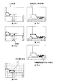
- FIG. 7 shows an image of the change area detection process of the change area detection apparatus 10 of the present embodiment.
- FIG. 7A-1 shows an input image (captured image), and FIG. 7B-1 shows a reference image.
- FIG. 7A-2 shows feature points in the input image
- FIG. 7B-2 shows feature points in the reference image.
- FIG. 7B-3 is a diagram showing a case where there is a feature point with a large distance between feature amounts in the reference image (that is, a case where a feature point not present in the input image is present in the reference image).
- the change area determination unit 22 determines that the area indicated by the thick frame in FIG. 7A-3 is a change (abnormal) area. That is, in the example of the figure, the document is carried away.
- the corresponding point search feature point selection unit 13 for selecting a feature point used to determine a reference image from feature points of an input image (captured image);
- a feature point selecting unit for geometric transformation parameter calculation which selects a feature point used to calculate a geometric transformation parameter from feature points of an input image and feature points of a reference image, feature points of the input image and a reference image
- a feature point selecting unit 20 for similarity calculation to select feature points used to obtain the similarity between the captured image and the reference image among the feature points, and the feature point selecting units 13, 18, 20
- the feature point selection suitable for determining the reference image, the feature point selection suitable for calculating the geometric transformation parameter, and the feature point selection suitable for calculating the degree of similarity are independently performed. As a result, it is possible to obtain an accurate reference image, an accurate geometric transformation parameter, and an accurate similarity without performing unnecessary calculations. As a result, the change area can be accurately determined with a small amount of calculation.
- the change area detection apparatus and method according to the present invention are suitably applied to, for example, a monitoring system using a wearable camera.
Landscapes
- Engineering & Computer Science (AREA)
- Computer Vision & Pattern Recognition (AREA)
- Theoretical Computer Science (AREA)
- Multimedia (AREA)
- General Physics & Mathematics (AREA)
- Physics & Mathematics (AREA)
- Evolutionary Computation (AREA)
- General Health & Medical Sciences (AREA)
- Medical Informatics (AREA)
- Software Systems (AREA)
- Databases & Information Systems (AREA)
- Computing Systems (AREA)
- Artificial Intelligence (AREA)
- Health & Medical Sciences (AREA)
- Image Analysis (AREA)
Abstract
Description
・上述したGPS等のセンサーを用いる方法
・画像のパターンマッチング等の画像処理を用いる方法の2つが考えられる。
x’=ax+by+c
y’=dx+ey+f ………(式1)
但し、(x,y)は入力画像(撮像画像)の特徴点の座標を示し、(x’,y’)は参照画像の特徴点の座標を示す。
11 特徴点検出部
12 特徴量算出部
13 対応点探索用特徴点選択部
14 対応点探索部
15 特徴量インデックス部
16 参照画像判定部
17 登録画像データベース
18 幾何変換パラメータ算出用特徴点選択部
19 幾何変換パラメータ算出部
20 類似度算出用特徴点選択部
21 類似度算出部
22 変化領域判定部
Claims (7)
- 撮像画像の特徴点を検出する特徴点検出部と、
複数の登録画像を格納する登録画像データベースと、
前記撮像画像の特徴点の中から、参照画像を決定するために用いる特徴点を選択する第1の特徴点選択部と、
前記第1の特徴点選択部によって選択された特徴点と、前記登録画像データベースに格納された各登録画像の特徴点とを用いて、前記撮像画像と各登録画像とのマッチング判定を行うことにより、前記複数の登録画像の中で前記撮像画像に最もマッチング度合いの高い画像を参照画像として決定する参照画像判定部と、
前記撮像画像の特徴点と前記参照画像の特徴点との中から、幾何変換パラメータを算出するために用いる特徴点を選択する第2の特徴点選択部と、
前記第2の特徴点選択部によって選択された特徴点を用いて、幾何変換パラメータを算出する幾何変換パラメータ算出部と、
前記撮像画像の特徴点と前記参照画像の特徴点との中から、前記撮像画像と前記参照画像との類似度を求めるために用いる特徴点を選択する第3の特徴点選択部と、
前記第3の特徴点選択部によって選択された特徴点を、前記幾何変換パラメータ算出部によって算出された幾何変換パラメータを用いて幾何変換し、幾何変換後の、前記撮像画像の特徴点と前記参照画像の特徴点の類似度を算出する類似度算出部と、
前記類似度算出部によって得られた類似度に基づいて、変化領域を判定する変化領域判定部と、
を具備する変化領域検出装置。 - 前記第1の特徴点選択部によって選択される特徴点は、前記第3の特徴点選択部によって選択される特徴点よりも疎である、
請求項1に記載の変化領域検出装置。 - 前記第2の特徴点選択部は、前記撮像画像の特徴点と前記参照画像の特徴点との間で、類似度が所定値以上の特徴点を選択する、
請求項1に記載の変化領域検出装置。 - 前記第2の特徴点選択部は、前記撮像画像の特徴点と前記参照画像の特徴点との間で、座標空間上の距離が所定値以上の特徴点を選択する、
請求項1に記載の変化領域検出装置。 - 前記第3の特徴点選択部は、前記撮像画像の特徴点と前記参照画像の特徴点との間で、類似度が所定値未満の特徴点を選択する、
請求項1に記載の変化領域検出装置。 - 前記第3の特徴点選択部は、前記撮像画像の特徴点と前記参照画像の特徴点との間で、座標空間上の距離が所定値以上の特徴点を選択する、
請求項1に記載の変化領域検出装置。 - 撮像画像と参照画像との類似度を算出し、この類似度に基づいて前記撮像画像中の変化領域を検出する変化領域検出方法であって、
前記撮像画像の特徴点の中から、前記参照画像を決定するために用いる特徴点を選択する第1の特徴点選択ステップと、
前記撮像画像の特徴点と前記参照画像の特徴点との中から、幾何変換パラメータを算出するために用いる特徴点を選択する第2の特徴点選択ステップと、
前記撮像画像の特徴点と前記参照画像の特徴点との中から、前記撮像画像と前記参照画像との類似度を求めるために用いる特徴点を選択する第3の特徴点選択ステップと、
を含む変化領域検出方法。
Priority Applications (2)
| Application Number | Priority Date | Filing Date | Title |
|---|---|---|---|
| CN201180037616.0A CN103052971B (zh) | 2010-07-30 | 2011-07-14 | 空间中的变化区域检测装置以及方法 |
| US13/811,796 US9064171B2 (en) | 2010-07-30 | 2011-07-14 | Detection device and method for transition area in space |
Applications Claiming Priority (2)
| Application Number | Priority Date | Filing Date | Title |
|---|---|---|---|
| JP2010172379A JP2012033022A (ja) | 2010-07-30 | 2010-07-30 | 空間における変化領域検出装置及び方法 |
| JP2010-172379 | 2010-07-30 |
Publications (1)
| Publication Number | Publication Date |
|---|---|
| WO2012014403A1 true WO2012014403A1 (ja) | 2012-02-02 |
Family
ID=45529637
Family Applications (1)
| Application Number | Title | Priority Date | Filing Date |
|---|---|---|---|
| PCT/JP2011/004029 Ceased WO2012014403A1 (ja) | 2010-07-30 | 2011-07-14 | 空間における変化領域検出装置及び方法 |
Country Status (4)
| Country | Link |
|---|---|
| US (1) | US9064171B2 (ja) |
| JP (1) | JP2012033022A (ja) |
| CN (1) | CN103052971B (ja) |
| WO (1) | WO2012014403A1 (ja) |
Cited By (2)
| Publication number | Priority date | Publication date | Assignee | Title |
|---|---|---|---|---|
| CN103049737A (zh) * | 2012-12-04 | 2013-04-17 | 中国核电工程有限公司 | 基于fpga的人员闸门视觉识别控制方法及系统 |
| TWI505201B (zh) * | 2012-08-23 | 2015-10-21 | Nec Corp | Object recognition device, object recognition method and program product |
Families Citing this family (16)
| Publication number | Priority date | Publication date | Assignee | Title |
|---|---|---|---|---|
| JP5919665B2 (ja) * | 2011-07-19 | 2016-05-18 | 日本電気株式会社 | 情報処理装置、物体追跡方法および情報処理プログラム |
| JP4976578B1 (ja) | 2011-09-16 | 2012-07-18 | 楽天株式会社 | 画像検索装置およびプログラム |
| JP5577372B2 (ja) * | 2012-03-29 | 2014-08-20 | 楽天株式会社 | 画像検索装置、画像検索方法、プログラムおよびコンピュータ読取り可能な記憶媒体 |
| JP5577371B2 (ja) * | 2012-03-29 | 2014-08-20 | 楽天株式会社 | 画像検索装置、画像検索方法およびプログラム |
| WO2014030399A1 (ja) * | 2012-08-23 | 2014-02-27 | 日本電気株式会社 | 物体識別装置、物体識別方法、及びプログラム |
| US10237687B2 (en) | 2014-09-02 | 2019-03-19 | Qualcomm Incorporated | Techniques for allocating positioning signal acquisition tasks among a plurality of co-located mobile devices |
| JP5857276B1 (ja) * | 2014-09-12 | 2016-02-10 | パナソニックIpマネジメント株式会社 | ウェアラブルカメラとそのユーザを認証する認証システム |
| JP6521626B2 (ja) * | 2014-12-25 | 2019-05-29 | キヤノン株式会社 | 被写体追跡装置、方法およびプログラム |
| CN105427529B (zh) * | 2015-12-04 | 2018-06-29 | 北京奇虎科技有限公司 | 一种车内环境监控的方法及终端 |
| KR101803018B1 (ko) * | 2016-09-05 | 2017-11-30 | 인천대학교 산학협력단 | 이미지에 기반한 형상 변화 탐지 방법 및 장치 |
| CN106845345A (zh) * | 2016-12-15 | 2017-06-13 | 重庆凯泽科技股份有限公司 | 活体检测方法及装置 |
| CN107633526B (zh) * | 2017-09-04 | 2022-10-14 | 腾讯科技(深圳)有限公司 | 一种图像跟踪点获取方法及设备、存储介质 |
| JP7230608B2 (ja) * | 2019-03-19 | 2023-03-01 | 株式会社明電舎 | 変更点検出装置、変更点検出方法及び変更点検出プログラム |
| JP6682167B2 (ja) * | 2019-04-02 | 2020-04-15 | 日本電信電話株式会社 | テンプレートマッチング装置、方法、及びプログラム |
| CN110018174B (zh) * | 2019-05-22 | 2021-10-22 | 合肥联宝信息技术有限公司 | 一种检测物体外观的方法和装置 |
| FR3126529B1 (fr) * | 2021-09-01 | 2024-10-25 | Kerquest | Procédé de mise en relation d’une image candidate avec une image de référence. |
Citations (5)
| Publication number | Priority date | Publication date | Assignee | Title |
|---|---|---|---|---|
| JP2002158999A (ja) * | 2000-08-31 | 2002-05-31 | Hitachi Kokusai Electric Inc | 物体検出方法及び物体検出装置並びに侵入物体監視装置 |
| JP2008257469A (ja) * | 2007-04-04 | 2008-10-23 | Canon Inc | 画像処理装置及び画像検索方法 |
| JP2009116385A (ja) * | 2007-11-01 | 2009-05-28 | Sony Corp | 情報処理装置および情報処理方法、画像識別装置および画像識別方法、並びに、プログラム |
| WO2009150882A1 (ja) * | 2008-06-10 | 2009-12-17 | 国立大学法人東京工業大学 | 画像位置合わせ処理装置、領域拡張処理装置及び画質改善処理装置 |
| JP2010134548A (ja) * | 2008-12-02 | 2010-06-17 | Ricoh Co Ltd | 情報処理装置、情報処理方法及び情報処理プログラム |
Family Cites Families (14)
| Publication number | Priority date | Publication date | Assignee | Title |
|---|---|---|---|---|
| US6453069B1 (en) * | 1996-11-20 | 2002-09-17 | Canon Kabushiki Kaisha | Method of extracting image from input image using reference image |
| US7082209B2 (en) | 2000-08-31 | 2006-07-25 | Hitachi Kokusai Electric, Inc. | Object detecting method and object detecting apparatus and intruding object monitoring apparatus employing the object detecting method |
| US7200270B2 (en) | 2001-12-13 | 2007-04-03 | Kabushiki Kaisha Toshiba | Pattern recognition apparatus and method using distributed model representation of partial images |
| JP3914864B2 (ja) | 2001-12-13 | 2007-05-16 | 株式会社東芝 | パターン認識装置及びその方法 |
| US7228006B2 (en) * | 2002-11-25 | 2007-06-05 | Eastman Kodak Company | Method and system for detecting a geometrically transformed copy of an image |
| JP4492036B2 (ja) * | 2003-04-28 | 2010-06-30 | ソニー株式会社 | 画像認識装置及び方法、並びにロボット装置 |
| JP4613617B2 (ja) * | 2005-01-07 | 2011-01-19 | ソニー株式会社 | 画像処理システム、学習装置および方法、並びにプログラム |
| JP4284288B2 (ja) * | 2005-03-10 | 2009-06-24 | 株式会社東芝 | パターン認識装置及びその方法 |
| JP4624287B2 (ja) * | 2006-03-17 | 2011-02-02 | 株式会社パスコ | 建物形状変化検出方法及び建物形状変化検出システム |
| JP4196302B2 (ja) * | 2006-06-19 | 2008-12-17 | ソニー株式会社 | 情報処理装置および方法、並びにプログラム |
| JP2008102907A (ja) * | 2006-09-19 | 2008-05-01 | Sharp Corp | 画像処理方法、画像処理装置、原稿読取装置、画像形成装置、コンピュータプログラム及び記録媒体 |
| JP4636064B2 (ja) * | 2007-09-18 | 2011-02-23 | ソニー株式会社 | 画像処理装置および画像処理方法、並びにプログラム |
| US8254690B2 (en) * | 2007-10-19 | 2012-08-28 | Sony Corporation | Information processing apparatus, information processing method, and program |
| CN100550054C (zh) | 2007-12-17 | 2009-10-14 | 电子科技大学 | 一种图像立体匹配方法及其装置 |
-
2010
- 2010-07-30 JP JP2010172379A patent/JP2012033022A/ja active Pending
-
2011
- 2011-07-14 US US13/811,796 patent/US9064171B2/en not_active Expired - Fee Related
- 2011-07-14 CN CN201180037616.0A patent/CN103052971B/zh not_active Expired - Fee Related
- 2011-07-14 WO PCT/JP2011/004029 patent/WO2012014403A1/ja not_active Ceased
Patent Citations (5)
| Publication number | Priority date | Publication date | Assignee | Title |
|---|---|---|---|---|
| JP2002158999A (ja) * | 2000-08-31 | 2002-05-31 | Hitachi Kokusai Electric Inc | 物体検出方法及び物体検出装置並びに侵入物体監視装置 |
| JP2008257469A (ja) * | 2007-04-04 | 2008-10-23 | Canon Inc | 画像処理装置及び画像検索方法 |
| JP2009116385A (ja) * | 2007-11-01 | 2009-05-28 | Sony Corp | 情報処理装置および情報処理方法、画像識別装置および画像識別方法、並びに、プログラム |
| WO2009150882A1 (ja) * | 2008-06-10 | 2009-12-17 | 国立大学法人東京工業大学 | 画像位置合わせ処理装置、領域拡張処理装置及び画質改善処理装置 |
| JP2010134548A (ja) * | 2008-12-02 | 2010-06-17 | Ricoh Co Ltd | 情報処理装置、情報処理方法及び情報処理プログラム |
Cited By (3)
| Publication number | Priority date | Publication date | Assignee | Title |
|---|---|---|---|---|
| TWI505201B (zh) * | 2012-08-23 | 2015-10-21 | Nec Corp | Object recognition device, object recognition method and program product |
| US9679221B2 (en) | 2012-08-23 | 2017-06-13 | Nec Corporation | Object identification apparatus, object identification method, and program |
| CN103049737A (zh) * | 2012-12-04 | 2013-04-17 | 中国核电工程有限公司 | 基于fpga的人员闸门视觉识别控制方法及系统 |
Also Published As
| Publication number | Publication date |
|---|---|
| US9064171B2 (en) | 2015-06-23 |
| CN103052971B (zh) | 2015-09-30 |
| US20130121535A1 (en) | 2013-05-16 |
| CN103052971A (zh) | 2013-04-17 |
| JP2012033022A (ja) | 2012-02-16 |
Similar Documents
| Publication | Publication Date | Title |
|---|---|---|
| CN103052971B (zh) | 空间中的变化区域检测装置以及方法 | |
| EP2915138B1 (en) | Systems and methods of merging multiple maps for computer vision based tracking | |
| CN114677418B (zh) | 一种基于点云特征点提取的配准方法 | |
| US8335354B2 (en) | Apparatus for registering face identification features, method for registering the same, program for registering the same, and recording medium | |
| US9330471B2 (en) | Camera aided motion direction and speed estimation | |
| JP5385105B2 (ja) | 画像検索方法およびシステム | |
| JP5680152B2 (ja) | オブジェクト検索方法、検索検証方法、及びその装置 | |
| JP5677798B2 (ja) | 3次元シーンにおける3次元物体の認識及び位置姿勢決定方法 | |
| WO2019140745A1 (zh) | 机器人定位方法及装置 | |
| JP6070956B2 (ja) | 類似性検出装置及び指向性近傍検出方法 | |
| CN110111375B (zh) | 一种Delaunay三角网约束下的影像匹配粗差剔除方法及装置 | |
| JPWO2009001876A1 (ja) | 特徴属性計算装置、特徴量抽出装置とパターン照合装置と方法及びプログラム | |
| Bhattacharya et al. | Improving RANSAC feature matching with local topological information | |
| JP5356289B2 (ja) | 画像検索システム | |
| Ekekrantz et al. | Adaptive iterative closest keypoint | |
| KR101700276B1 (ko) | 특징점 설정 장치 및 방법과 이를 이용한 객체 추적 장치 및 방법 | |
| Alcantarilla et al. | Learning visibility of landmarks for vision-based localization | |
| Hungar et al. | Detection of feature areas for map-based localization using LiDAR descriptors | |
| Peng et al. | KISS: Knowing camera prototype system for recognizing and annotating places-of-interest | |
| JP5819158B2 (ja) | 画像検索に適した特徴ベクトルを抽出するプログラム、方法及び画像検索装置 | |
| JPWO2025027757A5 (ja) | ||
| Lara–Alvarez et al. | Geometric indexing for recognition of places | |
| CN121810750A (zh) | 全局的重定位方法、装置、电子设备和存储介质 | |
| Gao et al. | Election based pose estimation of moving objects | |
| JP2005352990A (ja) | 部分画像検索システム及び方法並びにプログラム |
Legal Events
| Date | Code | Title | Description |
|---|---|---|---|
| WWE | Wipo information: entry into national phase |
Ref document number: 201180037616.0 Country of ref document: CN |
|
| 121 | Ep: the epo has been informed by wipo that ep was designated in this application |
Ref document number: 11812005 Country of ref document: EP Kind code of ref document: A1 |
|
| WWE | Wipo information: entry into national phase |
Ref document number: 13811796 Country of ref document: US |
|
| NENP | Non-entry into the national phase |
Ref country code: DE |
|
| 122 | Ep: pct application non-entry in european phase |
Ref document number: 11812005 Country of ref document: EP Kind code of ref document: A1 |