WO2012014253A1 - Thermostat device - Google Patents
Thermostat device Download PDFInfo
- Publication number
- WO2012014253A1 WO2012014253A1 PCT/JP2010/004761 JP2010004761W WO2012014253A1 WO 2012014253 A1 WO2012014253 A1 WO 2012014253A1 JP 2010004761 W JP2010004761 W JP 2010004761W WO 2012014253 A1 WO2012014253 A1 WO 2012014253A1
- Authority
- WO
- WIPO (PCT)
- Prior art keywords
- valve seat
- main valve
- valve body
- coolant
- cylindrical valve
- Prior art date
Links
Images


Classifications
-
- F—MECHANICAL ENGINEERING; LIGHTING; HEATING; WEAPONS; BLASTING
- F01—MACHINES OR ENGINES IN GENERAL; ENGINE PLANTS IN GENERAL; STEAM ENGINES
- F01P—COOLING OF MACHINES OR ENGINES IN GENERAL; COOLING OF INTERNAL-COMBUSTION ENGINES
- F01P7/00—Controlling of coolant flow
- F01P7/14—Controlling of coolant flow the coolant being liquid
- F01P7/16—Controlling of coolant flow the coolant being liquid by thermostatic control
-
- F—MECHANICAL ENGINEERING; LIGHTING; HEATING; WEAPONS; BLASTING
- F16—ENGINEERING ELEMENTS AND UNITS; GENERAL MEASURES FOR PRODUCING AND MAINTAINING EFFECTIVE FUNCTIONING OF MACHINES OR INSTALLATIONS; THERMAL INSULATION IN GENERAL
- F16K—VALVES; TAPS; COCKS; ACTUATING-FLOATS; DEVICES FOR VENTING OR AERATING
- F16K1/00—Lift valves or globe valves, i.e. cut-off apparatus with closure members having at least a component of their opening and closing motion perpendicular to the closing faces
- F16K1/32—Details
- F16K1/34—Cutting-off parts, e.g. valve members, seats
- F16K1/36—Valve members
-
- F—MECHANICAL ENGINEERING; LIGHTING; HEATING; WEAPONS; BLASTING
- F16—ENGINEERING ELEMENTS AND UNITS; GENERAL MEASURES FOR PRODUCING AND MAINTAINING EFFECTIVE FUNCTIONING OF MACHINES OR INSTALLATIONS; THERMAL INSULATION IN GENERAL
- F16K—VALVES; TAPS; COCKS; ACTUATING-FLOATS; DEVICES FOR VENTING OR AERATING
- F16K25/00—Details relating to contact between valve members and seat
-
- F—MECHANICAL ENGINEERING; LIGHTING; HEATING; WEAPONS; BLASTING
- F16—ENGINEERING ELEMENTS AND UNITS; GENERAL MEASURES FOR PRODUCING AND MAINTAINING EFFECTIVE FUNCTIONING OF MACHINES OR INSTALLATIONS; THERMAL INSULATION IN GENERAL
- F16K—VALVES; TAPS; COCKS; ACTUATING-FLOATS; DEVICES FOR VENTING OR AERATING
- F16K31/00—Actuating devices; Operating means; Releasing devices
- F16K31/002—Actuating devices; Operating means; Releasing devices actuated by temperature variation
-
- G—PHYSICS
- G05—CONTROLLING; REGULATING
- G05D—SYSTEMS FOR CONTROLLING OR REGULATING NON-ELECTRIC VARIABLES
- G05D23/00—Control of temperature
- G05D23/185—Control of temperature with auxiliary non-electric power
- G05D23/1852—Control of temperature with auxiliary non-electric power with sensing element expanding and contracting in response to change of temperature
Definitions
- the present invention relates to, for example, a thermostat device that controls the flow rate of coolant circulated in a cooling system circuit.
- FIG. 13 is a front sectional view showing the configuration of a representative embodiment of the thermostat device 101 proposed conventionally, and the main valve body 121 is opened with respect to the cylindrical valve seat 111 of the thermostat device 101. Show the situation.
- the thermostat device 101 is described as being installed on a cooling system circuit that circulates a coolant through a radiator and a bypass flow passage of an automobile engine.
- the thermostat device 101 is used by being fixed inside a thermostat housing 103 in which a cooling fluid flow channel chamber 103d is formed to allow the cooling fluid to flow in and out through various ports 103a, 103b, 103c.
- the main valve body 121 which closes the cylindrical valve seat 111 by entering the seat 111 and the cylindrical valve seat 111 to the inner side, and the temperature of the coolant is sensed to show the main valve body 121 in FIG.
- the temperature-sensitive movable body 131 is driven in the vertical direction.
- the thermostat device 101 has a support frame 133 whose both sides are fixed to a flange portion 113 provided in a flange shape on the outside of the cylindrical valve seat 111 and an upper end thereof supported at the center side of the support frame 133
- the lower end side further includes a piston shaft 135 housed in the temperature-sensitive movable body 131.
- the thermostat device 101 is provided between the frame 137 whose upper portion is fixed to the flange portion 113 of the cylindrical valve seat 111 and the main valve body 121 and the lower portion of the frame 137.
- the main spring 139 is biased to press the upper side.
- the main valve body 121 of the thermostat device 101 is on the inner peripheral side of the outer peripheral end 123c of the metal valve body 123 having a predetermined shape, and is upper than the upper surface of the outer peripheral end 123c.
- a convex portion 123d is formed to have a convex shape.
- An annular elastic body 125 made of synthetic rubber or the like having elasticity is adhered to an outer peripheral surface 123e of the convex portion 123d.
- the annular elastic body 125 and the convex portion 123d form a cylindrical valve seat at the time of valve closing.
- An entry portion 124 which enters to the inside of 111 is configured.
- An annular seal lip 127 resiliently pressed against the inner peripheral surface 111 a of the cylindrical valve seat 111 when the main valve body 121 is closed on the outer peripheral surface of the entry portion 124 which is the outer peripheral surface of the annular elastic body 125. Is provided.
- the thermal expansion body sealed inside the temperature-sensitive movable body 131 is thermally shrunk.
- the piston shaft 135 is pushed back from the illustrated state into the temperature-sensitive movable body 131 by the force of the main spring 139 urging the main valve body 121 in the valve closing direction.
- the upper surface of the outer peripheral end portion 123 c of the main valve body 121 contacts the lower surface of the flange portion 113 of the cylindrical valve seat 111.
- the main valve body 121 is closed with respect to the cylindrical valve seat 111 in a state of being in contact with and stationary.
- the annular seal lip 127 is elastically press-contacted to the inner peripheral surface 111 a of the cylindrical valve seat 111, thereby sealing the portion where the annular seal lip 127 is in pressure-contact.
- the thermal expansion body sealed in the temperature-sensitive movable body 131 thermally expands to push out the piston shaft 135.
- the temperature-sensitive movable body 131 moves downward in FIG. 13 together with the main valve body 121, and the annular seal lip 127 separates from the inner peripheral surface 111a of the cylindrical valve seat 111, as shown in FIG.
- the main valve body 121 is opened with respect to the cylindrical valve seat 111, and circulation of the coolant starts between the cylindrical valve seat 111 and the valve body main body 123.
- the piston shaft 135 expands and contracts due to thermal expansion and thermal contraction of the thermal expansion body in the temperature-sensitive movable body 131 according to the amount of temperature change of the coolant, whereby the main valve body 121 and the temperature-sensitive movable body 131 will move.
- the annular seal lip 127 of the main valve body 121 is provided along the circumferential direction without changing the position in the vertical direction in FIG.
- the annular seal lip 127 tends to be separated from the inner circumferential surface 111 a of the cylindrical valve seat 111 all at once. For this reason, for example, when the temperature rise of the coolant circulated through the inside of the engine is fast and the differential pressure between the upper and lower sides of the main valve body 121 by the water pump is large, the coolant cooled in the radiator opens. Immediately thereafter, the coolant rapidly flows from the lower side to the upper side in the drawing of the main valve body 121, and the cooled coolant flows into the engine cooling circuit at a stretch.
- the temperature of the cooling fluid in the cooling circuit causes an undershoot, and when the main valve body 121 is closed as a reaction, the temperature of the cooling fluid overshoots at this time, Due to the repetition of these phenomena, hunting may occur.
- this hunting may occur due to a large temperature range, and as a result, the engine may have a great adverse effect on the engine due to heat stress due to heat change.
- the coolant flow path gradually narrows from the upper side to the lower side of the main valve body at several locations of the annular elastic body provided in the vertical valve body portion of the main valve body.
- a notch is formed as such a V-shaped opening groove.
- the annular elastic body is bonded to the horizontal valve body portion of the main valve body, and the annular elastic body contacts and separates the lower surface of the horizontal valve seat portion of the cylindrical valve seat. An annular projection is provided to enable this.
- the thermostat device configured in this way allows a small amount of coolant to flow through this notch at the initial stage of valve opening after the main valve body has moved slightly from the valve closing state, and from this state the valve opening direction of the main valve body The flow rate of the coolant will operate to gradually increase as the amount of movement to the side increases.
- the outer peripheral end of the horizontal portion of the main valve body is bent toward the horizontal valve seat side of the cylindrical valve seat, and the annular elastic body is the horizontal direction of the main valve body. It is glued to the part.
- an annular projection is provided on the lower surface of the horizontal valve seat of the cylindrical valve seat so that the annular elastic body can come into and out of contact, and furthermore, the horizontal valve seat of the cylindrical valve seat Water holes are formed.
- the thermostat device configured in this way brings the annular seal lip of the annular elastic body into contact with the inner peripheral surface of the cylindrical valve seat at the time of valve closing, and the horizontal projection of the annular elastic body the horizontal valve seat of the cylindrical valve seat I am in contact with In the initial stage of valve opening, only the annular projection of the annular elastic member separates from the horizontal valve seat of the cylindrical valve seat, and a small amount of coolant passes through the water flow hole of the horizontal valve seat, and the main valve body and The flow rate before and after the cylindrical valve seat is controlled to a small flow rate.
- the notch is formed in a part of the annular elastic body including the annular seal lip made of synthetic rubber or the like, the opening and closing operation of the cylindrical valve seat and the main valve body is repeated.
- the shape of the notched portion may be deformed due to compression, sliding, or swelling of the annular elastic body at the time of deformation, and a change may occur in the flow rate characteristic at the time of opening and closing of the valve set in advance.
- Patent Document 2 is configured to use a water flow hole in order to make the valve opening initial flow small, but such water flow hole functions as a communication hole due to clogging or accumulation of foreign matter. There was a risk of losing
- the main When bringing the upper surface of the outer peripheral end of the valve body into contact with each other, the annular projection of the annular elastic body bonded to the upper surface of the outer peripheral end of the main valve body is elastically pressure-welded, It is configured to seal the portion where this is pressure-welded.
- the effective pressure receiving area of the pressure difference across the main valve body is increased as compared with the case where the inner peripheral surface of the cylindrical valve seat is sealed via the annular seal lip. For this reason, since the force acting on the main valve body by the differential pressure is increased, the stress received by the temperature sensitive movable body for driving the main valve body against this force is also increased, so that the temperature sensitive movable body May reduce the durability of the
- the main valve can move to a certain extent from the closed state, and the cooling can flow between the horizontal valve body and the horizontal valve seat rather than the coolant flow rate that can flow through the notch. From the time when the liquid flow rate becomes larger, the flow rate of the cooling liquid in the initial stage of valve opening can be adjusted by the notch of the annular elastic body.
- Patent Document 2 changes the flow rate of the coolant that can flow through the water flow hole in the initial stage of valve opening by changing the size, shape, etc. of the water flow hole formed in the horizontal valve seat. It can not be adjusted to gradually change according to the amount of movement of the body.
- the present invention has been made in view of the above-mentioned problems, and the object of the present invention is to stabilize the operation in the initial stage of valve opening and to circulate the coolant circulated in the cooling system circuit. It is an object of the present invention to provide a thermostat device capable of stabilizing the temperature and advantageously solving the above-mentioned problems.
- the invention according to claim 1 comprises a cylindrical valve seat, a main valve body for closing the cylindrical valve seat by being advanced to the inside of the cylindrical valve seat, and sensing the temperature of the coolant.
- a thermostat device including a temperature-sensitive movable body for driving a main valve body and controlling a flow rate of a coolant in an engine cooling circuit
- the outer valve of the main valve body entering the cylindrical valve seat is closed.
- An annular seal lip resiliently pressed against the inner peripheral surface of the cylindrical valve seat is sometimes provided, and the annular seal lip has a corrugated shape having an unevenness curved in the driving direction of the main valve body by the temperature sensitive movable body. It is characterized in that it is provided.
- a cylindrical valve seat, a main valve body for closing the cylindrical valve seat by being advanced to the inner side of the cylindrical valve seat, and a temperature of a coolant are sensed to detect the temperature.
- a thermostat device including a temperature-sensitive movable body for driving a main valve body back and forth and controlling a flow rate of a coolant in an engine cooling circuit, an outer periphery of an entrance portion of the main valve body to the cylindrical valve seat An annular seal lip elastically pressed against the inner peripheral surface of the cylindrical valve seat when the valve is closed is provided, and the cylindrical valve seat has a small diameter portion and an inlet / outlet side of the main valve body with respect to the small diameter portion.
- the annular seal lip has an inner diameter such that only the small diameter portion of the small diameter portion and the large diameter portion can be elastically press-contacted, and the small diameter portion and the large diameter portion And the boundary surface has a waveform having an unevenness curved in the driving direction of the main valve body by the temperature-sensitive movable body. And it is provided Te.
- the annular seal lip is provided in the form of a waveform having an unevenness curved in the driving direction of the main valve body by the temperature sensitive movable body, the cylindrical valve seat at the time of valve closing
- the contact position of the annular seal lip with the inner circumferential surface of the valve can be shifted in the driving direction of the main valve body in accordance with the circumferential position of the annular seal lip.
- the step portion of the cylindrical valve seat is provided in the form of a waveform having an unevenness curved in the driving direction of the main valve body by the temperature sensitive movable body, the initial stage of valve opening
- only a range extending in a part of the circumferential direction of the annular seal lip provided along the circumferential direction can be separated from the inner circumferential surface of the cylindrical valve seat.
- thermostat device installed on a cooling system circuit for circulating a coolant of an automobile engine through a radiator and a bypass flow path will be described in detail with reference to the drawings. .
- FIG. 1 is a block diagram showing an example of the cooling system circuit 6.
- the cooling system circuit 6 includes the engine 2 as an internal combustion engine, a radiator 4 for cooling a coolant, and a thermostat housing 3 in which a thermostat device 1 according to the present invention is disposed. It is configured as an engine cooling system circuit connected by 7c and a bypass flow path 7d. In the cooling system circuit 6, the coolant is circulated through driving of a pump or the like (not shown).
- FIGS. 1 to 3 are front sectional views showing a state in which the thermostat device 1 of the first embodiment according to the present invention is fixed in the thermostat housing 3, and FIG. 2 is a cylindrical valve seat 11 of the thermostat device 1.
- FIG. 3 shows a state in which the main valve body 21 is closed
- FIG. 3 shows a state in which the main valve body 21 is opened with respect to the cylindrical valve seat 11.
- the thermostat housing 3 is, as shown in FIGS. 1 to 3, a flow passage 7b connected to the radiator 4, a flow passage 7c connected to the engine 2, and a bypass flow passage 7d as a flow passage bypassing the radiator 4. They are connected via the radiator connection port 3a, the engine connection port 3b and the bypass connection port 3c, respectively.
- the thermostat housing 3 is configured by attaching a housing cover 53 in which a radiator side cooling fluid flow passage chamber 55b is provided to a housing main body 51 in which a temperature sensing chamber 55a as an engine side cooling fluid flow passage chamber is provided. ing.
- the coolant flows into and out of the coolant flow path chamber 55 composed of the temperature sensing chamber 55a of the thermostat housing 3 and the radiator side coolant flow path chamber 55b through the various ports 3a, 3b and 3c.
- thermostat device Next, a first embodiment of the thermostat device according to the present invention will be described in detail.
- the thermostat device 1 includes a cylindrical valve seat 11 and a main valve body 21 for closing the cylindrical valve seat 11 by being approached to the inside of the cylindrical valve seat 11, and senses the temperature of the cooling fluid.
- the temperature-sensitive movable body 31 which drives the valve body 21 is provided.
- the thermostat device 1 has a support frame 33 whose both sides are fixed to a flange portion 13 provided in a flange shape on the outside of the cylindrical valve seat 11, and an upper end thereof supported at the center side of the support frame 33
- the lower end side of the piston shaft 35 further includes a piston shaft 35 slidably housed relative to the temperature-sensitive movable body 31.
- the thermostat device 1 is provided between the frame 37 whose upper portion is fixed to the flange portion 13 of the cylindrical valve seat 11 and the main valve body 21 and the lower portion of the frame 37.
- a main spring 39 as biasing means for biasing the upper side.
- the drive direction of the main valve body 21 by the temperature-sensitive movable body 31 mentioned here means the thing of the up-down direction shown to FIG. 2, FIG. 3, and respond
- a packing 41 is attached to an outer peripheral end of the flange portion 13 provided in a flange shape on the outside of the cylindrical valve seat 11.
- the cylindrical valve seat 11 is fitted in a recessed groove formed in the inner peripheral wall of the thermostat housing 3 through a packing 41 to seal between the outer peripheral end of the flange portion 13 and the thermostat housing 3 It is being fixed in the thermostat housing 3 in the state.
- the main valve body 21 is configured by bonding an annular elastic body 25 made of synthetic rubber or the like having elasticity to a valve body main body 23 of a predetermined shape made of metal.
- the valve body 23 is provided with a cylindrical portion 23a provided on the center side and a flange portion 23b provided in a flange shape on the outside of the cylindrical portion 23a.
- the flange portion 23b of the valve body 23 has an outer peripheral end portion 23c whose upper surface is in contact with the lower surface of the flange portion 13 of the cylindrical valve seat 11 when the valve is closed.
- the flange portion 23b of the valve body 23 is formed with a convex portion 23d on the inner peripheral side with respect to the outer peripheral side end portion 23c and having a convex shape upward with respect to the upper surface of the outer peripheral side end portion 23c.
- An annular elastic body 25 is bonded to the outer peripheral surface 23 e of the convex portion 23 d so as to be interposed between the outer peripheral surface 23 e of the cylindrical valve seat 11 and the outer peripheral surface 23 e.
- An entrance portion 24 which enters to the inside of the cylindrical valve seat 11 when the valve is closed is constituted by 23 d and the annular elastic body 25.
- the outer peripheral side end portion 23 c of the flange portion 23 b of the valve body main body 23 is provided on the outer peripheral side than the entry portion 24.
- the annular elastic body 25 is provided with an annular seal lip 27 for the outer peripheral surface of the annular elastic body 25, in other words, for the outer peripheral surface of the entry portion 24 of the main valve body 21.
- the annular seal lip 27 is formed so that its cross-sectional shape is convex outward in the radial direction with respect to the outer peripheral surface of the annular elastic body 25.
- FIG. 2 when the main valve body 21 is closed, the annular seal lip 27 is elastically pressed against the inner peripheral surface 11 a of the cylindrical valve seat 11, thereby the annular seal lip 27. The part where the pressure is pressed is sealed.
- FIG. 4 is a view for explaining the shape of the annular seal lip 27 of the main valve body 21, and FIG. 4 (a) is a front view showing the appearance of the main valve body 21 and FIG. 4 (b) 4 is a rear view showing the appearance of the main valve body 21.
- FIG. FIG. 4C is a developed view of the annular elastic body 25 showing the locus of the tip of the annular seal lip 27 on the outer peripheral surface of the annular elastic body 25.
- the dashed-dotted line indicated by P1 to P3 in FIG. 4C indicates the same height as the height indicated by P1 to P3 in FIGS. 4A and 4B.
- the annular seal lip 27 is provided along the circumferential direction of the outer peripheral surface of the annular elastic body 25 in an undulating shape having an unevenness curved in the vertical direction.
- the waveform formed by the annular seal lip 27 is, as shown in FIG. 4C, formed in a range of 0 degree to 120 degree within a range over the entire circumference of the annular elastic body 25 in the circumferential direction.
- the waveform is formed so as to be repeated periodically for three times, with one waveform as a unit.
- the dashed-dotted line shown by P4 in FIG.4 (c) has shown the amplitude center of the waveform which this annular seal lip 27 makes.
- lower convex portions 28a provided on the lower side than the position that is the amplitude center of the waveform and upper convex portions 28b that are provided on the upper side than the position that is the amplitude center alternate.
- the wavelength of the lower convex portion 28 a is shorter than the wavelength of the upper convex portion 28 b.
- the contact position of the annular seal lip 27 with the inner peripheral surface 11 a of the cylindrical valve seat 11 at the time of valve closing is the circumferential position of the annular seal lip 27. 2 and 3 in accordance with the above. This will be described based on FIG. 2.
- the contact position of the annular seal lip 27 in the portion A in FIG. 2 with the inner peripheral surface 11a of the cylindrical valve seat 11 is rotated 180 degrees in the circumferential direction with respect to the portion A. It will be on the upper side in the figure than the contact point in the B section in FIG.
- thermo expansion body made of wax or the like which is thermally expanded or thermally shrunk according to the temperature change of the coolant flowing into the outer peripheral side is sealed inside.
- the main valve body 21 and the temperature-sensitive movable body 31 move integrally as a result of thermal expansion and contraction of the thermal expansion body in the temperature-sensitive movable body 31, and between the cylindrical valve seat 11 and the main valve body 21. Control the flow rate of the coolant.
- the thermostat device 1 when the temperature of the coolant flowing into the periphery of the temperature-sensitive movable body 31 is lower than a predetermined temperature at which the temperature-sensitive movable body 31 and the main valve body 21 start operating in the vertical direction, FIG. As shown, the main valve body 21 is closed with respect to the cylindrical valve seat 11. In this case, as described in the example shown in FIG. 1, the coolant is circulated through the bypass flow passage 7 d and the engine 2 without passing through the inside of the radiator 4.
- the thermal expansion body in the temperature-sensitive movable body 31 thermally expands, and the main valve body 21 and the temperature-sensitive movable body 31 Start moving downward.
- the main valve body 21 and the temperature-sensitive movable body 31 move by an amount corresponding to the temperature rise amount of the coolant, and the state shifts as shown in FIG. In this case, the amount of outflow of the low-temperature coolant from the radiator 4 is increased, and the coolant mixed with the coolant from the bypass flow path 7d at the portion of the range S7 indicated by the alternate long and short dash line It will flow into the engine 2.
- FIG. 5 is a partially enlarged view showing the operation state of the A portion and the B portion of FIG. 2 when the thermostat device 1 according to the first embodiment operates.
- annular seal lip 27 is elastically pressed against the inner peripheral surface 11 a of the cylindrical valve seat 11.
- the annular seal lip 27 is elastically pressed at the part shown by S1 in FIG. 5 (a) and the part shown by S2 in FIG. 5 (b). .
- FIGS. 5 (a) and 5 (b) show the state of the initial stage of valve opening after the main valve body 21 has moved a predetermined amount from the states shown in FIGS. 5 (a) and 5 (b). .
- portion A of FIG. 2 as shown in FIG. 5C, the annular seal lip 27 is elastically pressed against the inner peripheral surface 11a of the cylindrical valve seat 11 even in the initial stage of valve opening. It will remain.
- the annular seal lip 27 is elastically pressed at a portion shown by S3 in FIG. 5 (c).
- the annular seal lip 27 is separated from the inner peripheral surface 11a of the cylindrical valve seat 11 in the initial stage of valve opening.
- a coolant flow passage 29 is formed in the portion, and the coolant flows out at a low flow rate in the direction indicated by the arrow in the drawing through the coolant flow passage 29.
- the main valve body 21 is obtained from the state shown in FIG. As it moves downward in the drawing, which is the valve opening direction, it gradually increases in the circumferential direction, and the flow rate of the coolant passing through the coolant channel 29 gradually increases.
- FIGS. 5 (e) and 5 (f) show the state of the full-blown valve opening stage after the main valve body 21 has moved further by a predetermined amount from the states shown in FIGS. 5 (c) and 5 (d). There is. At this stage, the annular seal lip 27 is separated from the inner peripheral surface 11a of the cylindrical valve seat 11 in any of the portions A and B in FIG. Also, the coolant flow channel 29 is formed, and the coolant flows in the direction indicated by the arrow in the figure.
- the annular seal lip 27 is provided in a corrugated form having irregularities curved in the vertical direction, so that the inside of the cylindrical valve seat 11 at the time of valve closing is provided.
- the contact position of the annular seal lip 27 with the circumferential surface 11 a can be vertically shifted in accordance with the circumferential position of the annular seal lip 27.
- the coolant can be discharged at a small flow rate at the initial stage of valve opening, and the flow rate of the coolant can be gradually increased as the main valve body 21 moves in the valve opening direction.
- the flow rate increase / decrease amount of the cooling fluid according to the movement amount of the main valve body 21 is made small particularly at the first stage of the valve opening initial stage, and thereafter the movement amount of the main valve body 21 That the flow rate increase / decrease amount of the coolant can be increased according to the value, and the flow rate increase / decrease amount of the coolant according to the movement amount of the main valve body 21 at the initial stage of valve opening can be made moderately slow It has become. Therefore, it is possible to stabilize the valve opening operation by suppressing hunting at the initial stage of valve opening, and to stabilize the temperature of the coolant circulated in the cooling circuit. Further, the thermostat device 1 according to the first embodiment can obtain such an effect of stabilizing the valve opening operation with a simple and inexpensive configuration in which only the shape of the annular seal lip is changed.
- thermostat device 1 Next, a second embodiment of the thermostat device 1 according to the present invention will be described.
- the following description is abbreviate
- FIG. 6 is a partial cross-sectional front view showing an example of a use state of the thermostat device 1 of the second embodiment, and shows a state in which the main valve body 21 is opened with respect to the cylindrical valve seat 11.
- the thermostat device 1 of the second embodiment is different from the thermostat device 1 of the first embodiment only in the configurations of the annular seal lip 27 and the cylindrical valve seat 11.
- the annular seal lip 27 of the thermostat device 1 according to the second embodiment is not provided in the form of a waveform having an unevenness curved in the vertical direction, and the annular elastic body 25 is kept constant in the vertical direction in the figure.
- the outer circumferential surface of the main valve body 21 is provided along the circumferential direction with respect to the outer circumferential surface of the main valve body 21.
- FIG. 7 is a view for explaining the configuration of the cylindrical valve seat 11 of the thermostat device 1 according to the second embodiment, and FIG. 7 (a) is a front sectional view of the cylindrical valve seat 11; (B) is back surface sectional drawing of the cylindrical valve seat 11.
- FIG. 7 is a view for explaining the configuration of the cylindrical valve seat 11 of the thermostat device 1 according to the second embodiment, and FIG. 7 (a) is a front sectional view of the cylindrical valve seat 11; (B) is back surface sectional drawing of the cylindrical valve seat 11.
- the cylindrical valve seat 11 has a small diameter portion 15 and a large diameter portion 17 provided on the lower side in the figure, which is an entrance side of the main valve body 21 with respect to the small diameter portion 15, a small diameter portion 15 and a large diameter portion 17 And a step 19 formed therebetween.
- the large diameter portion 17 is formed so that its inner shape becomes larger in diameter than the small diameter portion 15.
- the small diameter portion 15 and the large diameter portion 17 only the small diameter portion 15 of the cylindrical valve seat 11 has an inner diameter such that the annular seal lip 27 can be elastically pressed.
- the stepped portion 19 of the cylindrical valve seat 11 has a curved inner peripheral surface in this embodiment, but between the inner peripheral surface of the small diameter portion 15 and the inner peripheral surface of the large diameter portion 17 If a level
- FIG. 7C is a developed view of the cylindrical valve seat 11 showing the locus of the step 19 on the inner peripheral surface of the cylindrical valve seat 11. As shown in FIG. The alternate long and short dash line indicated by P5 to P7 in FIG. 7C indicates the same height as the height indicated by P5 to P7 in FIGS. 7A and 7B.
- the stepped portion 19 of the cylindrical valve seat 11 is provided along the circumferential direction of the cylindrical valve seat 11 in a wave form having asperities curved in the vertical direction.
- the waveform formed by the step portion 19 is formed in the range of 0 degrees to 120 degrees within the range over the entire circumference of the cylindrical valve seat 11 in the circumferential direction.
- the waveform is formed so as to be repeated periodically for three times, with one waveform as a unit.
- the dashed-dotted line shown by P8 in FIG.7 (c) has shown the amplitude center of the waveform which this level
- a lower convex portion 56a provided below the position at which the amplitude center of the waveform is formed alternates with an upper convex portion 56b provided above the position at which the amplitude center is generated.
- the wavelength of the upper convex portion 56 b is shorter than the wavelength of the lower convex portion 56 a.
- the main valve body 21 is elastically pressed against the inner peripheral surface of the small diameter portion 15 of the cylindrical valve seat 11 in the range over the entire circumference when the valve seal is closed. The provided position in the vertical direction is adjusted.
- FIG. 8 is a partially enlarged view showing the operating state of the portions C and D of FIG. 6 when the thermostat device 1 according to the second embodiment is activated.
- annular seal lip 27 is elastically pressed against the inner peripheral surface 11 a of the cylindrical valve seat 11.
- the annular seal lip 27 is elastically pressed at the portion shown by S4 in FIG. 8A and the portion shown by S5 in FIG. 8B. .
- FIGS. 8C and 8D show the state of the initial stage of valve opening after the main valve body 21 has moved a predetermined amount from the states shown in FIGS. 8A and 8B. .
- a part of the annular seal lip 27 is separated from the inner peripheral surface of the small diameter portion 15 of the cylindrical valve seat 11 and the inside of the large diameter portion 17
- the main valve body 21 is moved downward in the figure until it is positioned radially inward with respect to the circumferential surface.
- the coolant flow passage 29 is formed in the D portion, and the coolant flows out at a small flow rate in the direction indicated by the arrow in the drawing through the coolant flow passage 29.
- FIGS. 8 (e) and 8 (f) show the state of the full-blown valve opening stage after the main valve body 21 has further moved a predetermined amount from the states shown in FIGS. 8 (c) and 8 (d). There is. At this stage, the annular seal lip 27 is separated from the inner peripheral surface of the small diameter portion 15 of the cylindrical valve seat 11 at any of the C and D portions in FIG. In any of the above, the coolant flow channel 29 is formed, and the coolant flows out in the direction indicated by the arrow in the figure.
- the step portion 19 of the cylindrical valve seat 11 is provided in a waveform having asperities curved in the vertical direction, in the initial stage of valve opening. It is possible to separate only the range covering a part of the circumferential direction of the annular seal lip 27 provided along the circumferential direction from the inner circumferential surface of the cylindrical valve seat 11.
- the coolant can be discharged at a small flow rate at the initial stage of valve opening, and the flow rate of the coolant can be gradually increased as the main valve body 21 moves in the valve opening direction.
- the flow rate increase / decrease amount of the cooling fluid according to the movement amount of the main valve body 21 is made small particularly at the first stage of the valve opening initial stage, and thereafter the movement amount of the main valve body 21 That the flow rate increase / decrease amount of the coolant can be increased according to the value, and the flow rate increase / decrease amount of the coolant according to the movement amount of the main valve body 21 at the initial stage of valve opening can be made moderately slow It has become. Therefore, it is possible to stabilize the valve opening operation by suppressing hunting at the initial stage of valve opening, and to stabilize the temperature of the coolant circulated in the cooling circuit.
- the thermostat device 1 according to the first embodiment and the second embodiment of the present invention further has the following configuration and effects.
- the thermostat device 1 According to the thermostat device 1 according to the present invention, it is not necessary to provide the water passage hole in the flange portion 13 in order to make the valve opening initial flow rate small, so there is a risk of loss of function due to clogging of foreign matter in the water passage hole. It goes without saying that there is no need to increase the size of the main valve body 21 as a whole, so it is possible to provide the thermostat device 1 excellent in achieving downsizing, weight reduction and cost reduction of the thermostat device 1.
- the annular seal lip 27 in the present invention is provided continuously over the entire outer periphery of the entry portion 24.
- the annular seal lip 27 does not need a notch, so the annular seal lip 27 caused by compression, sliding and swelling by the coolant when the main valve body 21 repeats opening and closing operations with respect to the cylindrical valve seat 11. This makes it difficult to cause a change in shape of the valve, and the possibility of a change in flow rate characteristics at the time of opening and closing of the valve set in advance can be significantly reduced.
- the main valve body 21 directly contacts the upper surface of the outer peripheral end 23c of the metal valve body 23 with the lower surface of the flange portion 13 of the cylindrical valve seat 11. It is preferable to close the valve in a state of being in contact, that is, without via an annular protrusion made of rubber as disclosed in Patent Document 1 and Patent Document 2. As a result, there is no fear that the pressure receiving effective area which has conventionally occurred becomes large or the change in the final closing position of the main valve body 21 at the time of closing the valve, and the durability of the temperature-sensitive movable body 31 is lowered. It is possible to exhibit the effect of stabilizing the operation at the initial stage of valve opening as described above without impairing the accuracy of the temperature control.
- the shape of the waveform formed by the annular seal lip 27 of the main valve body 21 of the first embodiment and the step portion 19 of the cylindrical valve seat 11 of the second embodiment may be periodic. It may be aperiodic. Moreover, in the first embodiment, this waveform is a waveform having the lower convex portion 28a and the upper convex portion 28b as one unit, and in the second embodiment, the lower convex portion 56a and the upper convex portion 56b are one unit. The waveform may be formed only once, or may be formed multiple times. When the waveform of one unit is formed a plurality of times, the shape, wavelength, and amplitude of each waveform may be different.
- the coolant flow passage 29 formed between the cylindrical valve seat 11 and the main valve body 21 at the initial stage of valve opening is circumferentially
- the waveform formed by the annular seal lip 27 of the first embodiment is formed so that the wavelength of the lower convex portion 28a is shorter than the wavelength of the upper convex portion 28b.
- these wavelengths are made the same and formed in a sinusoidal waveform, it is possible to reduce the coolant flow rate at the initial stage of valve opening. This is the same even when the wavelength of the upper convex portion 56b is shorter than the wavelength of the lower convex portion 56a, as described above, as described above. It can be said.
- the main valve body 21 moves from the valve closed state, and the curved convex portion 28a of the annular seal lip 27 separates from the inner peripheral surface 11a of the cylindrical valve seat 11. It is preferable that the cooling fluid is started to flow through the cooling fluid flow passage 29 formed between the cylindrical valve seat 11 and the convex portion of the annular seal lip 27 when the cooling fluid flows.
- the seal is performed without any gap between the main valve body 21 and the cylindrical valve seat 11 in the valve closed state, and the seal of the valve in the valve closed state when the main valve body 21 is moved.
- the final seal portion which is the portion that is lost first, will be the annular seal lip 27.
- the thermostat device 1 by adjusting the shape of the waveform formed by the annular seal lip 27, the flow rate increase / decrease of the coolant according to the movement amount of the main valve body 21 at the initial stage of valve opening. Since the amount can be adjusted, the final seal portion and the portion capable of adjusting the flow rate increase / decrease amount of the coolant are the same.
- the annular seal lip 27 can exert the function of adjusting the flow rate of the coolant to be gradually changed according to the movement amount of the main valve body 21. Also, this makes it possible to make the flow rate of the coolant flow moderately slow since the valve seal is lost at the final seal portion.
- the annular seal lip 27 of the main valve body 21 moves from the closed state to the curved convex portion 56b of the step portion 19 of the cylindrical valve seat 11,
- the annular seal lip 27 is separated from the inner peripheral surface of the small diameter portion 15 of the valve seat 11, the coolant flow passage 29 formed between the convex portion 56b of the cylindrical valve seat 11 and the annular seal lip 27 It is preferable that the flow of the cooling fluid is started through the above. Thereby, the annular seal lip 27 functions as a final seal portion.
- the thermostat device 1 by adjusting the shape of the waveform formed by the step portion 19 of the cylindrical valve seat 11, the movement amount of the main valve body 21 at the initial stage of valve opening was adjusted. Since the amount of increase or decrease in the flow rate of the coolant can be adjusted, the final seal portion and the portion capable of adjusting the amount of increase or decrease in the flow rate of the coolant are the same.
- the thermostat device 1 in the present invention may be used as an outlet controlled thermostat device, or an inlet control type installed at a site as shown in the range S7 of FIG. May be used as a thermostat device of Further, the thermostat device 1 of the present invention may be applied to, for example, a cooling system circuit in which an oil cooler is installed in the circuit and engine oil as a coolant is circulated.
- the above-mentioned cylindrical valve seat 11 and the main valve body 21 are formed into a predetermined shape by pressing a plate material made of metal and the like, and the annular elastic body 25 provided with the above-mentioned annular seal lip 27 is vulcanized. It is adhered to the main valve body 21 while being molded by adhesion or the like.
- the thermostat device of the first embodiment as shown in FIGS. 2 and 3 is taken as an example of the present invention
- the conventional thermostat device as shown in FIG. 13 is taken as a comparative example to compare these flow characteristics. I decided to consider it. Specifically, a constant differential pressure at a level normally generated in the engine cooling system circuit is applied before and after the main valve body and the cylindrical valve seat, and the movement amount (lift amount) from the valve closing state of the main valve body The flow rate of the cooling fluid passing through the cylindrical valve seat and flowing out to the side of the radiator connection port is compared between the present invention example and the comparative example.
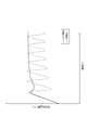
- FIG. 9 is a graph showing the relationship of the flow rate to the lift amount in the first embodiment
- FIG. 10 is a graph in which a range S8 indicated by an alternate long and short dash line in FIG. 9 is enlarged.
- the flow rate of the coolant according to the present invention is larger than that of the comparative example. It can be confirmed that the increase is small, the flow rate of the coolant can be gradually increased, and it is possible to make the flow rate increase / decrease of the coolant moderately slow.
- the flow rate of the coolant according to the present invention is substantially the same as the flow rate of the coolant according to the comparative example in the full opening stage where the amount of movement of the main valve is large.
- the same differential pressure as that of the first embodiment is used before and after the main valve body and the cylindrical valve seat by using the thermostat device as the present invention example and the comparative example similar to the first embodiment.
- the amount of movement (lift amount) of the main valve body and the flow rate of the coolant are compared and studied in the inventive example and the comparative example.
- FIG. 11 is a graph showing the relationship between the lift amount and the flow rate at the initial stage of valve opening in the second embodiment. As shown in FIG. 11, it can be confirmed that the flow rate increases gradually in the example of the present invention while the flow rate increases rapidly immediately after the valve opening in the comparative example.
- thermostat devices as present invention examples and comparative examples similar to the first embodiment are installed on an engine cooling system circuit of a car to warm up the engine, and at the engine outlet side at that time. It was decided to compare and examine the liquid temperature transition of the coolant in the present invention example and the comparative example.
- FIG. 12 is a graph showing the relationship of the temperature of the coolant to the passage of time in Example 3. As shown in FIG. 12, while hunting is occurring in the comparative example, it can be confirmed that hunting can be suppressed in the example of the present invention.
- thermostat device 3 thermostat housing 5 coolant flow passage 11 cylindrical valve seat 13 flange portion 15 small diameter portion 17 large diameter portion 19 step portion 21 main valve body 23 valve body 23a cylindrical portion 23b flange portion 23c outer peripheral side end portion 23d Convex part 24 Entry part 25 Annular elastic body 27 Annular seal lip 29 Coolant flow path 31 Temperature-sensitive movable body 33 Support frame 35 Piston shaft 37 Frame 39 Main spring 41 Packing
Abstract
Description
3 サーモスタットハウジング
5 冷却液流路
11 筒状弁座
13 フランジ部
15 小径部
17 大径部
19 段差部
21 主弁体
23 弁体本体
23a 筒状部
23b フランジ部
23c 外周側端部
23d 凸状部
24 進入部
25 環状弾性体
27 環状シールリップ
29 冷却液流路
31 感温可動体
33 支持枠
35 ピストンシャフト
37 フレーム
39 メインスプリング
41 パッキン
Claims (2)
- 筒状弁座と、前記筒状弁座の内側まで進入させられることで当該筒状弁座を閉弁する主弁体と、冷却液の温度を感知して前記主弁体を駆動させる感温可動体とを備え、冷却系回路内で冷却液の流量を制御するサーモスタット装置において、
前記主弁体の前記筒状弁座への進入部外周には、閉弁時に当該筒状弁座の内周面に弾性的に圧接される環状シールリップが設けられ、
前記環状シールリップは、前記感温可動体による前記主弁体の駆動方向に湾曲した凹凸を有する波形をなして設けられていること
を特徴とするサーモスタット装置。 A cylindrical valve seat, a main valve body closing the cylindrical valve seat by being advanced to the inner side of the cylindrical valve seat, and a temperature sensing device which senses the temperature of the coolant and drives the main valve body In a thermostat device including a movable body and controlling a flow rate of a coolant in a cooling system circuit,
An annular seal lip is provided on an outer periphery of the main valve body entering the cylindrical valve seat, the annular seal lip being elastically pressed against the inner peripheral surface of the cylindrical valve seat when the valve is closed,
The thermostat device, wherein the annular seal lip is provided in a corrugated form having an unevenness curved in a driving direction of the main valve body by the temperature sensitive movable body. - 筒状弁座と、前記筒状弁座の内側まで進入させられることで当該筒状弁座を閉弁する主弁体と、冷却液の温度を感知して前記主弁体を前後に駆動させる感温可動体とを備え、エンジン冷却回路内で冷却液の流量を制御するサーモスタット装置において、
前記主弁体の前記筒状弁座への進入部外周には、閉弁時に当該筒状弁座の内周面に弾性的に圧接される環状シールリップが設けられ、
前記筒状弁座は、小径部と当該小径部に対して前記主弁体の進入口側に設けられる大径部とを有し、前記小径部と前記大径部とのうち小径部のみが前記環状シールリップが弾性的に圧接可能な内径とされ、前記小径部と前記大径部との間に形成される段差部が前記感温可動体による前記主弁体の駆動方向に湾曲した凹凸を有する波形をなして設けられていること
を特徴とするサーモスタット装置。 A cylindrical valve seat, a main valve body closing the cylindrical valve seat by being advanced to the inside of the cylindrical valve seat, and sensing a temperature of a coolant to drive the main valve body back and forth In a thermostat device including a temperature sensitive movable body and controlling a flow rate of a coolant in an engine cooling circuit,
An annular seal lip is provided on an outer periphery of the main valve body entering the cylindrical valve seat, the annular seal lip being elastically pressed against the inner peripheral surface of the cylindrical valve seat when the valve is closed,
The cylindrical valve seat has a small diameter portion and a large diameter portion provided on the entrance side of the main valve body with respect to the small diameter portion, and only the small diameter portion of the small diameter portion and the large diameter portion The annular seal lip has an inner diameter which can be elastically press-contacted, and an uneven portion formed between the small diameter portion and the large diameter portion is curved in a driving direction of the main valve body by the temperature sensitive movable body. A thermostat device provided in a corrugated form.
Priority Applications (5)
| Application Number | Priority Date | Filing Date | Title |
|---|---|---|---|
| KR1020117006336A KR101286474B1 (en) | 2010-07-27 | 2010-07-27 | Thermostat Apparatus |
| US13/812,647 US9217358B2 (en) | 2010-07-27 | 2010-07-27 | Thermostat device with formed seal |
| PCT/JP2010/004761 WO2012014253A1 (en) | 2010-07-27 | 2010-07-27 | Thermostat device |
| CN201080068253.2A CN103026113B (en) | 2010-07-27 | 2010-07-27 | Thermostat device |
| EP10855264.7A EP2600046B1 (en) | 2010-07-27 | 2010-07-27 | Thermostat device |
Applications Claiming Priority (1)
| Application Number | Priority Date | Filing Date | Title |
|---|---|---|---|
| PCT/JP2010/004761 WO2012014253A1 (en) | 2010-07-27 | 2010-07-27 | Thermostat device |
Publications (1)
| Publication Number | Publication Date |
|---|---|
| WO2012014253A1 true WO2012014253A1 (en) | 2012-02-02 |
Family
ID=45529505
Family Applications (1)
| Application Number | Title | Priority Date | Filing Date |
|---|---|---|---|
| PCT/JP2010/004761 WO2012014253A1 (en) | 2010-07-27 | 2010-07-27 | Thermostat device |
Country Status (5)
| Country | Link |
|---|---|
| US (1) | US9217358B2 (en) |
| EP (1) | EP2600046B1 (en) |
| KR (1) | KR101286474B1 (en) |
| CN (1) | CN103026113B (en) |
| WO (1) | WO2012014253A1 (en) |
Cited By (1)
| Publication number | Priority date | Publication date | Assignee | Title |
|---|---|---|---|---|
| CN115751663A (en) * | 2022-11-28 | 2023-03-07 | 贵州电网有限责任公司 | Automatic regulating device and method for heat dissipation load of central air conditioner external unit |
Families Citing this family (13)
| Publication number | Priority date | Publication date | Assignee | Title |
|---|---|---|---|---|
| JP2015086974A (en) * | 2013-10-31 | 2015-05-07 | ヤマハ発動機株式会社 | Thermostat, water cooling device, water cooling engine, and outboard engine |
| FR3034162B1 (en) * | 2015-03-24 | 2018-09-21 | Vernet | THERMOSTATIC DEVICE FOR CONTROLLING CIRCULATION OF A FLUID, AND THERMOSTATIC VALVE COMPRISING SUCH A DEVICE |
| US10754364B2 (en) * | 2015-10-27 | 2020-08-25 | Dana Canada Corporation | Multi-stage by-pass valve |
| JP6591270B2 (en) * | 2015-11-30 | 2019-10-16 | 愛三工業株式会社 | Pressure regulating valve |
| FR3044782B1 (en) | 2015-12-07 | 2018-01-12 | Vernet | THERMOSTATIC MONOCOMMANDE CARTRIDGE AND MIXER FAUCET WITH SUCH A CARTRIDGE |
| FR3050512B1 (en) | 2016-04-26 | 2018-09-28 | Vernet | MIXING UNIT AND MIXER TAP COMPRISING SUCH A MIXING UNIT |
| FR3050510B1 (en) | 2016-04-26 | 2018-09-21 | Vernet | MIXING UNIT AND MIXER TAP COMPRISING SUCH A MIXING UNIT |
| FR3054282B1 (en) | 2016-07-21 | 2018-08-31 | Vernet | MIXING UNIT AND MIXER TAP COMPRISING SUCH A MIXING UNIT |
| TR201612859A2 (en) * | 2016-09-08 | 2017-01-23 | Kirpart Otomotiv Parcalari Sanayi Ve Ticaret A S | ASSEMBLY METHOD OF A THERMO ACTUATOR AND SEALING ELEMENT |
| KR20180031999A (en) * | 2016-09-21 | 2018-03-29 | 인지컨트롤스 주식회사 | Thermostat valve |
| SE1950844A1 (en) * | 2019-07-04 | 2021-01-05 | Purmo Group Sweden Ab | Valve arrangement |
| FR3103021B1 (en) * | 2019-11-13 | 2022-01-21 | Vernet | Thermostatic device for regulating the circulation of a fluid, as well as corresponding thermostatic valve and method of manufacturing such a device |
| JP7393371B2 (en) * | 2021-02-17 | 2023-12-06 | 日本サーモスタット株式会社 | thermostat device |
Citations (8)
| Publication number | Priority date | Publication date | Assignee | Title |
|---|---|---|---|---|
| JPS60125471A (en) * | 1983-12-12 | 1985-07-04 | Hitachi Constr Mach Co Ltd | Spool valve |
| JPS63164672U (en) * | 1987-04-15 | 1988-10-26 | ||
| JPS63312576A (en) * | 1987-06-12 | 1988-12-21 | Kubota Ltd | Spool directional control valve |
| JPH0339670U (en) * | 1989-08-28 | 1991-04-17 | ||
| JPH0599351A (en) * | 1991-10-11 | 1993-04-20 | Hitachi Ltd | Spool type hydraulic control valve |
| JPH07305787A (en) | 1994-03-14 | 1995-11-21 | Nippon Thermostat Kk | Thermostat |
| JPH10252903A (en) * | 1997-03-17 | 1998-09-22 | Kayaba Ind Co Ltd | Fluid force reducing structure of spool valve |
| JPH11351441A (en) | 1998-06-05 | 1999-12-24 | Fuji Thomson Kk | Thermally actuated valve to control automobile engine refrigerant circulating circuit |
Family Cites Families (9)
| Publication number | Priority date | Publication date | Assignee | Title |
|---|---|---|---|---|
| US4164322A (en) * | 1973-08-01 | 1979-08-14 | Standard-Thomson Corporation | Thermostatic valve device having non-linear flow characteristics |
| JPS63164672A (en) | 1986-12-26 | 1988-07-08 | Ricoh Co Ltd | Image reader |
| US4763834A (en) * | 1987-06-25 | 1988-08-16 | Standard-Thomson Corporation | Valve seat structure for automotive thermostatic fluid control valve device |
| JPH0339670A (en) | 1989-07-06 | 1991-02-20 | Tokyo Electric Power Co Inc:The | Partial discharge measuring method |
| DE69426027T2 (en) * | 1994-12-09 | 2001-05-17 | Nippon Thermostat Kk | Thermally controlled valve |
| US5690276A (en) * | 1996-10-31 | 1997-11-25 | Caltherm | Two stage thermostatic valve device |
| US6138617A (en) * | 1997-04-11 | 2000-10-31 | Kuze; Yoshikazu | Cooling system for an automotive engine |
| CA2246462C (en) * | 1998-04-03 | 2004-05-11 | Yoshikazu Kuze | Cooling system for an automotive engine |
| JP4400909B2 (en) * | 2003-04-04 | 2010-01-20 | 日本サーモスタット株式会社 | Thermostat device |
-
2010
- 2010-07-27 KR KR1020117006336A patent/KR101286474B1/en not_active IP Right Cessation
- 2010-07-27 US US13/812,647 patent/US9217358B2/en active Active
- 2010-07-27 WO PCT/JP2010/004761 patent/WO2012014253A1/en active Application Filing
- 2010-07-27 CN CN201080068253.2A patent/CN103026113B/en active Active
- 2010-07-27 EP EP10855264.7A patent/EP2600046B1/en active Active
Patent Citations (8)
| Publication number | Priority date | Publication date | Assignee | Title |
|---|---|---|---|---|
| JPS60125471A (en) * | 1983-12-12 | 1985-07-04 | Hitachi Constr Mach Co Ltd | Spool valve |
| JPS63164672U (en) * | 1987-04-15 | 1988-10-26 | ||
| JPS63312576A (en) * | 1987-06-12 | 1988-12-21 | Kubota Ltd | Spool directional control valve |
| JPH0339670U (en) * | 1989-08-28 | 1991-04-17 | ||
| JPH0599351A (en) * | 1991-10-11 | 1993-04-20 | Hitachi Ltd | Spool type hydraulic control valve |
| JPH07305787A (en) | 1994-03-14 | 1995-11-21 | Nippon Thermostat Kk | Thermostat |
| JPH10252903A (en) * | 1997-03-17 | 1998-09-22 | Kayaba Ind Co Ltd | Fluid force reducing structure of spool valve |
| JPH11351441A (en) | 1998-06-05 | 1999-12-24 | Fuji Thomson Kk | Thermally actuated valve to control automobile engine refrigerant circulating circuit |
Cited By (1)
| Publication number | Priority date | Publication date | Assignee | Title |
|---|---|---|---|---|
| CN115751663A (en) * | 2022-11-28 | 2023-03-07 | 贵州电网有限责任公司 | Automatic regulating device and method for heat dissipation load of central air conditioner external unit |
Also Published As
| Publication number | Publication date |
|---|---|
| EP2600046A4 (en) | 2014-01-08 |
| EP2600046A1 (en) | 2013-06-05 |
| US9217358B2 (en) | 2015-12-22 |
| CN103026113B (en) | 2015-01-07 |
| CN103026113A (en) | 2013-04-03 |
| KR101286474B1 (en) | 2013-07-16 |
| US20130126624A1 (en) | 2013-05-23 |
| KR20120082816A (en) | 2012-07-24 |
| EP2600046B1 (en) | 2021-06-09 |
Similar Documents
| Publication | Publication Date | Title |
|---|---|---|
| WO2012014253A1 (en) | Thermostat device | |
| KR100755264B1 (en) | Thermostat apparatus | |
| US8701603B2 (en) | Control valve unit for a liquid circuit | |
| US7757960B2 (en) | Thermostat valve for a cooling system of a combustion engine | |
| JP5215184B2 (en) | Automotive coolant pump equipment | |
| US8291561B2 (en) | Thermostat installing structure | |
| US20010002646A1 (en) | Multifunction rocker switch | |
| US8827172B2 (en) | Thermostat valve | |
| KR20100092002A (en) | Heat exchanger, particularly an oil cooler | |
| JP2000314437A (en) | Fluid coupling device | |
| US20120006438A1 (en) | Accumulator | |
| EP2818960B1 (en) | Membrane for dynamic valve | |
| WO2020018340A1 (en) | Coolant valve for a vehicle | |
| JP4682253B2 (en) | Thermostat device | |
| US5961037A (en) | Engine coolant thermostat with overtemperature protection | |
| US20130334328A1 (en) | Dual-valve thermostat | |
| US5813598A (en) | Thermostat device for protecting an engine of a vehicle from overheating | |
| JP2003336753A (en) | Flow control valve and its manufacturing method | |
| WO2022163068A1 (en) | Thermostat device | |
| JP7078270B2 (en) | Thermo actuator | |
| JP2022115622A (en) | thermostat device | |
| WO2000057042A1 (en) | Thermostat device | |
| JP2020026858A (en) | Thermostat device | |
| JP2002004859A (en) | Wax-type thermally-driven control valve for engine refrigerant circulating circuit | |
| WO2018087747A1 (en) | Thermostat assembly with pressure compensation |
Legal Events
| Date | Code | Title | Description |
|---|---|---|---|
| WWE | Wipo information: entry into national phase |
Ref document number: 201080068253.2 Country of ref document: CN |
|
| ENP | Entry into the national phase |
Ref document number: 20117006336 Country of ref document: KR Kind code of ref document: A |
|
| 121 | Ep: the epo has been informed by wipo that ep was designated in this application |
Ref document number: 10855264 Country of ref document: EP Kind code of ref document: A1 |
|
| NENP | Non-entry into the national phase |
Ref country code: DE |
|
| WWE | Wipo information: entry into national phase |
Ref document number: 13812647 Country of ref document: US |
|
| WWE | Wipo information: entry into national phase |
Ref document number: 2010855264 Country of ref document: EP |
|
| NENP | Non-entry into the national phase |
Ref country code: JP |