WO2012011397A1 - 基板加熱炉 - Google Patents
基板加熱炉 Download PDFInfo
- Publication number
- WO2012011397A1 WO2012011397A1 PCT/JP2011/065705 JP2011065705W WO2012011397A1 WO 2012011397 A1 WO2012011397 A1 WO 2012011397A1 JP 2011065705 W JP2011065705 W JP 2011065705W WO 2012011397 A1 WO2012011397 A1 WO 2012011397A1
- Authority
- WO
- WIPO (PCT)
- Prior art keywords
- core tube
- substrate
- heating furnace
- substrate heating
- peripheral side
- Prior art date
- Legal status (The legal status is an assumption and is not a legal conclusion. Google has not performed a legal analysis and makes no representation as to the accuracy of the status listed.)
- Ceased
Links
Images



Classifications
-
- H—ELECTRICITY
- H10—SEMICONDUCTOR DEVICES; ELECTRIC SOLID-STATE DEVICES NOT OTHERWISE PROVIDED FOR
- H10P—GENERIC PROCESSES OR APPARATUS FOR THE MANUFACTURE OR TREATMENT OF DEVICES COVERED BY CLASS H10
- H10P72/00—Handling or holding of wafers, substrates or devices during manufacture or treatment thereof
- H10P72/04—Apparatus for manufacture or treatment
- H10P72/0431—Apparatus for thermal treatment
- H10P72/0436—Apparatus for thermal treatment mainly by radiation
-
- H—ELECTRICITY
- H10—SEMICONDUCTOR DEVICES; ELECTRIC SOLID-STATE DEVICES NOT OTHERWISE PROVIDED FOR
- H10P—GENERIC PROCESSES OR APPARATUS FOR THE MANUFACTURE OR TREATMENT OF DEVICES COVERED BY CLASS H10
- H10P72/00—Handling or holding of wafers, substrates or devices during manufacture or treatment thereof
- H10P72/04—Apparatus for manufacture or treatment
- H10P72/0431—Apparatus for thermal treatment
- H10P72/0434—Apparatus for thermal treatment mainly by convection
Definitions
- the present invention relates to a substrate heating furnace.
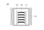
- FIG. 5 shows an internal configuration diagram of the conventional substrate heating furnace 110 of the first example.
- the substrate heating furnace 110 of the first example includes a furnace core tube 111, a multistage flat plate susceptor 113, and a resistance heater 115.
- the flat plate susceptor 113 is disposed in the core tube 111 and is configured to be able to hold a plurality of substrates 112 stacked horizontally.
- the resistance heater 115 is disposed outside the core tube 111 and is configured to heat the core tube 111.
- the substrate heating furnace 110 of the first example is called a hot wall type.
- the substrate heating furnace 110 particularly when a nitride layer is formed on the substrate 112, when a reaction gas containing nitrogen in the chemical structure is introduced into the core tube 111, a part of the reaction gas is in the core tube. Since the substrate 111 is decomposed by heat, it is not used for nitriding the substrate 112, that is, the substrate 112 cannot be efficiently nitrided. In addition, since the substrate 112 is not directly heated, there is a problem that the heating rate of the substrate 112 is slower than lamp heating described later.
- FIG. 6 shows an internal configuration diagram of a conventional substrate heating furnace 210 of the second example.
- the substrate heating furnace 210 of the second example includes a furnace core tube 211, a flat plate susceptor 213, a lamp heater 215, and a cooling device 216.
- the flat plate susceptor 213 is disposed in the core tube 211 and is configured to hold a single substrate 212 horizontally.
- the lamp heater 215 is disposed above the furnace core tube 211 and is configured to heat the surface of the substrate 212 by irradiating infrared rays.
- the cooling device 216 is attached to the outer periphery of the wall surface of the core tube 211 and configured to cool the core tube 211.
- the substrate heating furnace 210 of the second example is called a cold wall type.
- the reaction gas introduced into the core tube 211 reaches the surface of the substrate 212 without being decomposed at the wall surface, and is efficiently used for the reaction with the substrate 212.
- the number of the substrates 212 that can be heated in one process is one, and there is a problem that the productivity is inferior.
- the lower substrate enters the shadow of the upper substrate, and the lower substrate is irradiated with infrared rays. There is a problem in that each of the substrates cannot be heated evenly because a portion that is not formed occurs.
- the present invention was created to solve the disadvantages of the prior art described above, and an object thereof is to provide a substrate heating furnace capable of simultaneously heating a plurality of substrates while cooling the core tube.
- the present invention provides a reactor core tube formed in a cylindrical shape with ceramics that transmits infrared rays, and is disposed inside the reactor core tube so that the substrate faces the inner peripheral side surface of the reactor core tube.
- a substrate holding portion that is directed toward the outside, a reflector that is disposed outside the core tube, and a surface facing the outer peripheral side surface of the core tube is configured to reflect infrared rays, and between the core tube and the reflector.
- a lamp heater disposed in a tube, a cylindrical flow path forming cylinder disposed around the outer peripheral side surface of the core tube at a position spaced from the outer peripheral side surface of the core tube, and the core tube and the flow path formation
- This invention is a substrate heating furnace, Comprising:
- the said flow path formation cylinder is a substrate heating furnace comprised with the said reflector.
- This invention is a substrate heating furnace, Comprising:
- maintenance part is a substrate heating furnace comprised so that multiple said substrates could be hold
- This invention is a substrate heating furnace, Comprising:
- maintenance part is a substrate heating furnace arrange
- the present invention is a substrate heating furnace having a rotating device that rotates the substrate holding portion about a central axis of the furnace core tube.
- the present invention is a substrate heating furnace, wherein the lamp heater is configured to be able to heat the substrate held by the substrate holding unit to 1400 ° C. or more, and the substrate holding unit includes silicon carbide and silicon carbide.
- the substrate heating furnace is made of any one material selected from the group consisting of graphite and alumina coated on the surface.
- the present invention is a substrate heating furnace, wherein the furnace core tube is made of quartz.
- the mass productivity of the substrates can be improved. Since the core tube can be cooled, the reaction gas is not decomposed on the wall surface of the core tube, and the reaction gas and the substrate can be reacted efficiently. Since the substrate can be heated to a high temperature of 1400 ° C. or higher, it can be used to form a gate oxide film on the SiC substrate.
- Internal configuration diagram of the substrate heating furnace of the present invention Sectional view taken along line AA of the substrate heating furnace of the present invention Schematic showing the side of one branch and one plate Internal configuration diagram of another example of the substrate heating furnace of the present invention Internal configuration diagram of the first example of a conventional substrate heating furnace Internal configuration diagram of a second example of a conventional substrate heating furnace
- FIG. 1 is an internal configuration diagram of the substrate heating furnace 10, and FIG. 2 is a sectional view taken along the line AA.
- the substrate heating furnace 10 is disposed inside the core tube 11 formed in a cylindrical shape with ceramics that transmit infrared rays, and holds the substrate 12 in a direction facing the inner peripheral side surface of the core tube 11.
- a substrate holding portion 13 that is disposed on the outside of the core tube 11, and a reflector 14 that is configured to reflect infrared rays on a surface facing the outer peripheral side surface of the core tube 11, and between the core tube 11 and the reflector 14.
- a blower unit 17 that blows a fluid that transmits infrared rays
- a reaction gas supply unit 18 that supplies a reaction gas that reacts with the substrate 12 inside the core tube 11.
- a rotating shaft 22 is disposed on the central axis of the core tube 11 inside the core tube 11.
- the substrate holding portion 13 has a plurality of rod-like branch portions 23 and a plurality of plate-like plate portions 24 each here.
- Each branch portion 23 is fixed at a same position (position of the same height) along the longitudinal direction of the rotation shaft 22 at a right angle to the rotation shaft 22 and radially fixed around the rotation shaft 22.
- Each plate portion 24 is attached to the tip of a different branch portion 23 such that the surface thereof is directed to face the inner peripheral side surface of the core tube 11.
- FIG. 3 is a schematic view showing the side surfaces of one branch portion 23 and one plate portion 24.
- the central axis of the core tube 11 is oriented in the vertical direction.
- the plate part 24 is fixed to the tip of the branch part 23 in a state where the surface is inclined with respect to the vertical direction so that the surface faces obliquely upward, and a convex part 25 protruding from the surface is provided at the lower end of the plate part 24.
- the substrate 12 is placed on the surface of the plate portion 24, the edge of the substrate 12 comes into contact with the side surface of the convex portion 25, and the substrate 12 is supported and held so as not to slide off from the surface of the plate portion 24. ing. Therefore, as shown in FIG. 2, the substrate holder 13 is configured to hold a plurality of substrates 12 along the circumferential direction of the core tube 11.
- a plurality of substrate holders 13 are arranged along the central axis of the core tube 11.
- the lamp heaters 15 are rod-shaped here, and a plurality of lamp heaters 15 are arranged along the circumferential direction of the core tube 11 with the longitudinal direction thereof being parallel to the central axis of the core tube 11.
- the row of substrate holders 13 arranged along the central axis of the core tube 11 is called a substrate holder row
- the length in the longitudinal direction of the lamp heater 15 is equal to or longer than the length of the substrate holder row here.
- the substrate holders 13 can face the lamp heaters 15 respectively.
- the lamp heater 15 is not limited to the length in the longitudinal direction equal to or longer than the length of the substrate holder row.
- the length in the longitudinal direction is shorter than the length of the substrate holding portion row, and a plurality of the holding portions 13 are arranged along the central axis of the core tube 11 so that each substrate holding portion 13 can face the lamp heater 15. It may be like this.
- infrared rays When infrared rays are emitted from the lamp heater 15, a part of the emitted infrared rays is directly incident on the core tube 11, and the remaining infrared rays are incident on the reflector 14 and reflected, and then enter the core tube 11.
- the material of the core tube 11 is quartz here, and the incident infrared rays are transmitted through the wall surface of the core tube 11. Infrared rays that have passed through the wall surface of the core tube 11 enter the surface of the substrate 12 held by the substrate holding unit 13 and the substrate holding unit 13 to heat the surface of the substrate 12 and the substrate holding unit 13.
- the temperature of the surface of the substrate 12 can be increased in a shorter time than resistance heating or high-frequency heating (RF).
- the lamp heater 15 is configured to be able to heat the surface of the substrate 12 to 1400 ° C. or higher
- the substrate holder 13 is a group consisting of silicon carbide, graphite whose surface is coated with silicon carbide, and alumina. Are formed of any one kind of material. Therefore, the substrate holding part 13 is not melted even when heated to 1400 ° C. or higher.
- the reflector 14 is disposed so as to surround the outer peripheral side surface of the furnace core tube 11, and the flow path forming cylinder 31 is configured by the reflector 14.
- the blower unit 17 is disposed at the lower end of the flow path 19 here.
- the air in 19 is discharged from the lower end to the outside of the flow path 19.
- the air in the flow path 19 is discharged by the blower unit 17, the air is sucked inward from the upper end of the flow path 19, and the sucked air is parallel to the central axis of the core tube 11 from the upper end to the lower end in the flow path 19. And is discharged from the lower end of the flow path 19.
- the air flowing in the flow path 19 comes into contact with the outer peripheral side surface of the core tube 11, absorbs the heat of the core tube 11, and the core tube 11 is cooled.
- the air flowing in the flow path 19 is preferably dry air. This is because when water molecules are contained in the air, infrared rays are absorbed by the water molecules.
- the fluid flowing in the flow path 19 is not limited to air as long as it transmits infrared rays, and may be other gas or liquid, but air is preferable because of its low cost.
- the reactive gas supply unit 18 is connected to the reactor core tube 11 and is configured to be able to release a reactive gas that reacts with the surface of the substrate 12 inside the reactor core tube 11.
- the material of the substrate 12 is SiC
- the reaction gas supply unit 18 uses any one kind of gas among O 2 gas, N 2 O gas, NO gas, and NO 2 gas or two or more kinds of mixed gases as a reaction gas. As it can be released.
- One end of a cylindrical connecting tube 45 is connected to one end of the core tube 11 in an airtight manner, and the loading / unloading chamber 41 is connected to the other end of the connecting tube 45 through a first vacuum gate valve 42 in an airtight manner. .
- a first vacuum exhaust device 16 is connected to the connection pipe 45, and a second vacuum exhaust device 44 is connected to the carry-in / out chamber 41.
- the second evacuation device 44 is configured to be able to evacuate the carry-in / out chamber 41.
- the rotary shaft 22 extends through the inside of the connection pipe 45 and the inside of the loading / unloading chamber 41, passes through the wall surface of the loading / unloading chamber 41 in an airtight manner, and is arranged on the outside of the loading / unloading chamber 41. 21 is connected.
- the moving rotating device 21 is configured to be able to rotate the rotating shaft 22 around the central axis of the core tube 11, and is configured to be able to move the rotating shaft 22 in a direction parallel to the central axis of the core tube 11. .
- the moving rotating device 21 includes a rotating device 21a that rotates the rotating shaft 22 around the central axis of the core tube 11, and a parallel moving device 21b that moves the rotating shaft 22 in a direction parallel to the central axis of the core tube 11.
- the substrate holding unit 13 rotates around the central axis of the core tube 11.
- the substrate holder 13 can reciprocate between the core tube 11 and the loading / unloading chamber 41.
- a second vacuum gate valve 43 is attached to the wall surface of the carry-in / out chamber 41. When the second vacuum gate valve 43 is opened while the substrate holding part 13 is moved into the loading / unloading chamber 41, the substrate holding part 13 is exposed from the opening of the second vacuum gate valve 43. Yes.
- the flow path forming cylinder 31 is constituted by the reflector 14.
- the flow path forming cylinder 31 of the present invention is not limited to this configuration, and a core tube such as a substrate heating furnace denoted by reference numeral 10 ′ in FIG. 4. 11 is disposed between the outer peripheral side surface of the heater 11 and the lamp heater 15, and a flow path forming cylinder 31, which is different from the reflector 14 made of a material that transmits infrared rays, is disposed between the core tube 11 and the flow path forming cylinder 31. You may comprise so that the flow path 19 may be formed in between.
- the lamp heater 15 since the lamp heater 15 is not exposed to the flow path 19, the lamp heater 15 is cooled by the air flowing through the flow path 19, and a temperature difference is generated between the upstream side and the downstream side of the lamp heater 15.
- the lamp heater 15 can emit infrared rays with a uniform amount of light over the longitudinal direction.
- the substrate heating furnace 10 is configured to rotate the substrate holding unit 13 around the central axis of the core tube 11, but the substrate 12 held by the substrate holding unit 13 is surrounded by the core tube 11.
- the present invention is not limited to this as long as the lamp heaters 15 arranged in the direction can be evenly faced, and the lamp heaters 15 may be configured to rotate around the central axis of the core tube 11. .
- the central axis of the core tube 11 is oriented in the vertical direction, but a configuration in which the central axis of the core tube 11 is oriented in the horizontal direction is also included in the present invention.
- the reflector 14 has a cylindrical shape in which the inner diameter is larger than the outer diameter of the core tube 11, and two semi-cylindrical portions 14a and 14b are formed by one plane along the central axis. It can be divided into two. When the reflector 14 is divided into two semi-cylindrical portions 14a and 14b, the core tube 11 is taken out from the inside of the reflector 14 so that the core tube 11 can be maintained.
- a substrate processing method using the substrate heating furnace 10 of the present invention will be described by taking a method of forming a gate oxide layer on a SiC substrate as an example.
- the substrate holder 13 is moved into the loading / unloading chamber 41 and is kept stationary.
- the first vacuum gate valve 42 is closed, and the inside of the core tube 11 is evacuated by the first evacuation device 16. Thereafter, evacuation by the first evacuation device 16 is continued and the vacuum atmosphere in the core tube 11 is maintained.
- the second vacuum gate valve 43 is opened, and the substrate 12 is placed on the surface of the substrate holding part 13 exposed from the opening of the second vacuum gate valve 43.
- a plurality of substrates 12 are placed on each substrate holding unit 13 while rotating the substrate holding unit 13 about the central axis of the rotation shaft 22.
- One substrate holding unit 13 among the plurality of substrate holding units 13 will be described.
- the substrates 12 are placed one by one on each plate unit 24.
- a SiC substrate is used as the substrate 12.
- the second vacuum gate valve 43 is closed, and the inside of the loading / unloading chamber 41 is evacuated by the second evacuation device 44. Thereafter, the evacuation by the second evacuation device 44 is continued to maintain the vacuum atmosphere in the loading / unloading chamber 41.
- the first vacuum gate valve 42 is opened and the substrate holder 13 is moved into the core tube 11, the first vacuum gate valve 42 is closed. Air is passed through the flow path 19 by the blower 17 to cool the core tube 11. Thereafter, the cooling of the core tube 11 by the blower 17 is continued. Infrared rays are emitted from the lamp heater 15.
- the emitted infrared light passes through the wall surface of the core tube 11 and is applied to the surface of the substrate 12 held by the substrate holding unit 13 and the substrate holding unit 13.
- the substrate holder 13 is rotated about the central axis of the rotation shaft 22, infrared rays are evenly applied to the surface of each substrate 12.
- the substrate 12 and the substrate holding part 13 are heated to 1400 ° C. or higher.
- a reactive gas is supplied from the reactive gas supply unit 18 into the core tube 11.
- any one kind of gas or two or more kinds of mixed gases among O 2 gas, N 2 O gas, NO gas, and NO 2 gas is used as the reaction gas.
- the reaction gas supplied into the furnace core tube 11 reaches the surface of the heated substrate 12, it reacts to form a gate oxide layer on the surface of the substrate 12. Since the core tube 11 is cooled by the air flowing through the flow path 19, the reaction gas is not thermally decomposed on the wall surface of the core tube 11 and lost.
- the infrared radiation from the lamp heater 15 is stopped, and the supply of the reaction gas from the reaction gas supply unit 18 is stopped.
- the rotation of the substrate holding unit 13 by the moving rotation device 21 is stopped.
- the first vacuum gate valve 42 is opened to move the substrate holder 13 into the loading / unloading chamber 41, and the first vacuum gate valve 42. Close.
- the second vacuum gate valve 43 is opened, the substrate 12 is removed from the substrate holder 13, carried out to the outside of the loading / unloading chamber 41, and sent to the next process.
- the unprocessed substrate 12 is placed on the substrate holder 13 and the above steps are repeated.
Abstract
炉心管を冷却しながら、同時に複数枚の基板を加熱できる基板加熱炉を提供する。 炉心管11を赤外線を透過するセラミックスで形成し、炉心管11の内周側面と対面する向きに向けられて基板保持部13に保持された基板12に、炉心管11とリフレクタ14との間に配置されたランプ加熱ヒーター15から赤外線を照射して加熱する。リフレクタ14は炉心管11の外周側面と離間した位置に、炉心管11の外周側面を取り囲んで配置され、炉心管11とリフレクタ14との間の流路19に送風部17により空気等の赤外線を透過する流体が吹き流されて、炉心管11が冷却される。
Description
本発明は、基板加熱炉に関する。
現在、SiC-MOSトランジスタは動作時の電力損失が少なく、動作温度の上限が高いという特徴があり、パワー半導体として注目されている。SiC-MOSトランジスタのゲート酸化層の形成には、基板加熱炉が用いられている。
図5は従来の第一例の基板加熱炉110の内部構成図を示している。
第一例の基板加熱炉110は、炉心管111と、多段の平板サセプタ113と、抵抗加熱ヒーター115とを有している。
平板サセプタ113は炉心管111内に配置され、複数枚の基板112を水平に重ねて保持できるように構成されている。
抵抗加熱ヒーター115は炉心管111の外側に配置され、炉心管111を加熱できるように構成されている。炉心管111が加熱されると、炉心管111内の複数の基板112が同時に加熱されるようになっている。基板112を加熱するためにはまず炉心管111を加熱する必要があり、第一例の基板加熱炉110はホットウォール型と呼ばれている。
ホットウォール型の基板加熱炉110では、特に基板112に窒化層を形成する場合には、化学構造中に窒素を含有する反応ガスを炉心管111内に導入すると、反応ガスの一部は炉心管111の壁面で熱により分解されてしまうため基板112の窒化には使われず、すなわち基板112を効率的に窒化できないという課題があった。また、基板112は直接加熱されないため、後述のランプ加熱に比べて、基板112の昇温速度が遅いという問題があった。
図5は従来の第一例の基板加熱炉110の内部構成図を示している。
第一例の基板加熱炉110は、炉心管111と、多段の平板サセプタ113と、抵抗加熱ヒーター115とを有している。
平板サセプタ113は炉心管111内に配置され、複数枚の基板112を水平に重ねて保持できるように構成されている。
抵抗加熱ヒーター115は炉心管111の外側に配置され、炉心管111を加熱できるように構成されている。炉心管111が加熱されると、炉心管111内の複数の基板112が同時に加熱されるようになっている。基板112を加熱するためにはまず炉心管111を加熱する必要があり、第一例の基板加熱炉110はホットウォール型と呼ばれている。
ホットウォール型の基板加熱炉110では、特に基板112に窒化層を形成する場合には、化学構造中に窒素を含有する反応ガスを炉心管111内に導入すると、反応ガスの一部は炉心管111の壁面で熱により分解されてしまうため基板112の窒化には使われず、すなわち基板112を効率的に窒化できないという課題があった。また、基板112は直接加熱されないため、後述のランプ加熱に比べて、基板112の昇温速度が遅いという問題があった。
図6は従来の第二例の基板加熱炉210の内部構成図を示している。
第二例の基板加熱炉210は、炉心管211と、平板サセプタ213と、ランプ加熱ヒーター215と、冷却装置216とを有している。
平板サセプタ213は炉心管211内に配置され、一枚の基板212を水平に保持できるように構成されている。
ランプ加熱ヒーター215は炉心管211の上方に配置され、基板212の表面に赤外線を照射して加熱できるように構成されている。冷却装置216は炉心管211の壁面の外周に取り付けられ、炉心管211を冷却できるように構成されている。基板212を加熱するために炉心管211を加熱する必要はなく、第二例の基板加熱炉210はコールドウォール型と呼ばれている。炉心管211内に導入された反応ガスは、壁面で分解されずに基板212表面に到達し、基板212との反応に効率的に使用される。
しかしながら、第二例の基板加熱炉210では一回のプロセスで加熱できる基板212は一枚であり、量産性に劣るという課題があった。量産性を上げるために、仮に第一例のように多段の平板サセプタに複数枚の基板を重ねて保持させると、下方の基板が上方の基板の陰に入って、下方の基板に赤外線が照射されない部分が生じるため、各基板を均等に加熱できないという問題があった。
第二例の基板加熱炉210は、炉心管211と、平板サセプタ213と、ランプ加熱ヒーター215と、冷却装置216とを有している。
平板サセプタ213は炉心管211内に配置され、一枚の基板212を水平に保持できるように構成されている。
ランプ加熱ヒーター215は炉心管211の上方に配置され、基板212の表面に赤外線を照射して加熱できるように構成されている。冷却装置216は炉心管211の壁面の外周に取り付けられ、炉心管211を冷却できるように構成されている。基板212を加熱するために炉心管211を加熱する必要はなく、第二例の基板加熱炉210はコールドウォール型と呼ばれている。炉心管211内に導入された反応ガスは、壁面で分解されずに基板212表面に到達し、基板212との反応に効率的に使用される。
しかしながら、第二例の基板加熱炉210では一回のプロセスで加熱できる基板212は一枚であり、量産性に劣るという課題があった。量産性を上げるために、仮に第一例のように多段の平板サセプタに複数枚の基板を重ねて保持させると、下方の基板が上方の基板の陰に入って、下方の基板に赤外線が照射されない部分が生じるため、各基板を均等に加熱できないという問題があった。
本発明は上記従来技術の不都合を解決するために創作されたものであり、その目的は、炉心管を冷却しながら、同時に複数枚の基板を加熱できる基板加熱炉を提供することにある。
上記課題を解決するために本発明は、赤外線を透過するセラミックスで筒状に形成された炉心管と、前記炉心管の内側に配置され、基板を前記炉心管の内周側面と対面する向きに向けて保持する基板保持部と、前記炉心管の外側に配置され、前記炉心管の外周側面と対面する面は赤外線を反射できるように構成されたリフレクタと、前記炉心管と前記リフレクタとの間に配置されたランプ加熱ヒーターと、前記炉心管の外周側面と離間した位置に、前記炉心管の外周側面を取り囲んで配置された筒状の流路形成筒と、前記炉心管と前記流路形成筒との間の空間に、赤外線を透過する流体を吹き流す送風部と、前記炉心管の内側に前記基板と反応する反応ガスを供給する反応ガス供給部と、を有する基板加熱炉である。
本発明は基板加熱炉であって、前記流路形成筒は前記リフレクタで構成された基板加熱炉である。
本発明は基板加熱炉であって、前記基板保持部は、前記基板を前記炉心管の周方向に沿って複数個保持できるように構成された基板加熱炉である。
本発明は基板加熱炉であって、前記基板保持部は、前記炉心管の中心軸線に沿って複数個配置された基板加熱炉である。
本発明は基板加熱炉であって、前記基板保持部を前記炉心管の中心軸線を中心に回転させる回転装置を有する基板加熱炉である。
本発明は基板加熱炉であって、前記ランプ加熱ヒーターは、前記基板保持部に保持された前記基板を1400℃以上に加熱できるように構成され、前記基板保持部は、炭化ケイ素と、炭化ケイ素で表面を被膜されたグラファイトと、アルミナとからなる群のうちいずれか一種類の材質で形成された基板加熱炉である。
本発明は基板加熱炉であって、前記炉心管の材質は石英である基板加熱炉である。
本発明は基板加熱炉であって、前記流路形成筒は前記リフレクタで構成された基板加熱炉である。
本発明は基板加熱炉であって、前記基板保持部は、前記基板を前記炉心管の周方向に沿って複数個保持できるように構成された基板加熱炉である。
本発明は基板加熱炉であって、前記基板保持部は、前記炉心管の中心軸線に沿って複数個配置された基板加熱炉である。
本発明は基板加熱炉であって、前記基板保持部を前記炉心管の中心軸線を中心に回転させる回転装置を有する基板加熱炉である。
本発明は基板加熱炉であって、前記ランプ加熱ヒーターは、前記基板保持部に保持された前記基板を1400℃以上に加熱できるように構成され、前記基板保持部は、炭化ケイ素と、炭化ケイ素で表面を被膜されたグラファイトと、アルミナとからなる群のうちいずれか一種類の材質で形成された基板加熱炉である。
本発明は基板加熱炉であって、前記炉心管の材質は石英である基板加熱炉である。
同時に複数枚の基板を加熱できるので、基板の量産性を向上できる。
炉心管を冷却できるので、反応ガスが炉心管の壁面で分解されることはなく、反応ガスと基板を効率的に反応させることができる。
基板を1400℃以上の高温に加熱できるので、SiC基板上のゲート酸化膜の形成に使用できる。
炉心管を冷却できるので、反応ガスが炉心管の壁面で分解されることはなく、反応ガスと基板を効率的に反応させることができる。
基板を1400℃以上の高温に加熱できるので、SiC基板上のゲート酸化膜の形成に使用できる。
<基板加熱炉の構造>
本発明の基板加熱炉の構造を説明する。
図1は基板加熱炉10の内部構成図、図2は同A-A線切断断面図を示している。
基板加熱炉10は、赤外線を透過するセラミックスで筒状に形成された炉心管11と、炉心管11の内側に配置され、基板12を炉心管11の内周側面と対面する向きに向けて保持する基板保持部13と、炉心管11の外側に配置され、炉心管11の外周側面と対面する面は赤外線を反射できるように構成されたリフレクタ14と、炉心管11とリフレクタ14との間に配置されたランプ加熱ヒーター15と、炉心管11の外周側面と離間した位置に、炉心管11の外周側面を取り囲んで配置された筒状の流路形成筒31と、炉心管11と流路形成筒31との間の空間に、赤外線を透過する流体を吹き流す送風部17と、炉心管11の内側に基板12と反応する反応ガスを供給する反応ガス供給部18とを有している。
炉心管11の内側には炉心管11の中心軸線上に回転軸22が配置されている。
本発明の基板加熱炉の構造を説明する。
図1は基板加熱炉10の内部構成図、図2は同A-A線切断断面図を示している。
基板加熱炉10は、赤外線を透過するセラミックスで筒状に形成された炉心管11と、炉心管11の内側に配置され、基板12を炉心管11の内周側面と対面する向きに向けて保持する基板保持部13と、炉心管11の外側に配置され、炉心管11の外周側面と対面する面は赤外線を反射できるように構成されたリフレクタ14と、炉心管11とリフレクタ14との間に配置されたランプ加熱ヒーター15と、炉心管11の外周側面と離間した位置に、炉心管11の外周側面を取り囲んで配置された筒状の流路形成筒31と、炉心管11と流路形成筒31との間の空間に、赤外線を透過する流体を吹き流す送風部17と、炉心管11の内側に基板12と反応する反応ガスを供給する反応ガス供給部18とを有している。
炉心管11の内側には炉心管11の中心軸線上に回転軸22が配置されている。
図2を参照し、基板保持部13はここでは棒状の枝部23と板状の板部24とをそれぞれ複数個ずつ有している。
各枝部23は、回転軸22の長手方向に沿った同一の位置(互いに同じ高さの位置)に、回転軸22に対して直角に向けられて回転軸22を中心とする放射状に固定されている。
各板部24は、表面が炉心管11の内周側面と対面する向きに向けられて、それぞれ異なる枝部23の先端に取り付けられている。
各枝部23は、回転軸22の長手方向に沿った同一の位置(互いに同じ高さの位置)に、回転軸22に対して直角に向けられて回転軸22を中心とする放射状に固定されている。
各板部24は、表面が炉心管11の内周側面と対面する向きに向けられて、それぞれ異なる枝部23の先端に取り付けられている。
図3は一の枝部23と一の板部24との側面を示した模式図である。
ここでは炉心管11の中心軸線は鉛直方向に向けられている。板部24は表面が斜め上方を向くように鉛直方向に対して傾けられた状態で枝部23の先端に固定され、板部24の下端には表面から突出した凸部25が設けられている。
板部24の表面に基板12を載せると、基板12の縁が凸部25の側面と接触して、基板12は板部24の表面から滑り落ちないように支えられ、保持されるようになっている。
従って、図2に示すように、基板保持部13は、基板12を炉心管11の周方向に沿って複数個保持できるように構成されている。
ここでは炉心管11の中心軸線は鉛直方向に向けられている。板部24は表面が斜め上方を向くように鉛直方向に対して傾けられた状態で枝部23の先端に固定され、板部24の下端には表面から突出した凸部25が設けられている。
板部24の表面に基板12を載せると、基板12の縁が凸部25の側面と接触して、基板12は板部24の表面から滑り落ちないように支えられ、保持されるようになっている。
従って、図2に示すように、基板保持部13は、基板12を炉心管11の周方向に沿って複数個保持できるように構成されている。
図1を参照し、ここでは基板保持部13は、炉心管11の中心軸線に沿って複数個並んで配置されている。
ランプ加熱ヒーター15はここでは棒状であり、長手方向を炉心管11の中心軸線と平行に向けられて、炉心管11の周方向に沿って複数個並んで配置されている。
炉心管11の中心軸線に沿って並んだ基板保持部13の列を基板保持部列と呼ぶと、ランプ加熱ヒーター15の長手方向の長さは、ここでは基板保持部列の長さと同じかそれよりも長く形成されており、各基板保持部13はそれぞれランプ加熱ヒーター15と対面できるようになっている。
各基板保持部13がそれぞれランプ加熱ヒーター15と対面できるならば、本発明のランプ加熱ヒーター15は、長手方向の長さが基板保持部列の長さと同じかそれよりも長いものに限定されず、長手方向の長さが基板保持部列の長さよりも短く形成され、炉心管11の中心軸線に沿って複数本並んで配置されて、各基板保持部13がそれぞれランプ加熱ヒーター15と対面できるようになっていてもよい。
ランプ加熱ヒーター15はここでは棒状であり、長手方向を炉心管11の中心軸線と平行に向けられて、炉心管11の周方向に沿って複数個並んで配置されている。
炉心管11の中心軸線に沿って並んだ基板保持部13の列を基板保持部列と呼ぶと、ランプ加熱ヒーター15の長手方向の長さは、ここでは基板保持部列の長さと同じかそれよりも長く形成されており、各基板保持部13はそれぞれランプ加熱ヒーター15と対面できるようになっている。
各基板保持部13がそれぞれランプ加熱ヒーター15と対面できるならば、本発明のランプ加熱ヒーター15は、長手方向の長さが基板保持部列の長さと同じかそれよりも長いものに限定されず、長手方向の長さが基板保持部列の長さよりも短く形成され、炉心管11の中心軸線に沿って複数本並んで配置されて、各基板保持部13がそれぞれランプ加熱ヒーター15と対面できるようになっていてもよい。
ランプ加熱ヒーター15から赤外線を放射させると、放射された赤外線の一部は炉心管11に直接入射し、残りの赤外線はリフレクタ14に入射して反射された後、炉心管11に入射する。
炉心管11の材質はここでは石英であり、入射する赤外線は炉心管11の壁面を透過するようになっている。
炉心管11の壁面を透過した赤外線は、基板保持部13に保持された基板12の表面と、基板保持部13とに入射し、基板12の表面と基板保持部13とを加熱する。赤外線により基板12の表面を直接加熱するので、抵抗加熱や高周波加熱(RF)に比べて、短時間で基板12の表面を昇温できる。
ここではランプ加熱ヒーター15は、基板12の表面を1400℃以上に加熱できるように構成され、基板保持部13は、炭化ケイ素と、炭化ケイ素で表面を被膜されたグラファイトと、アルミナとからなる群のうちいずれか一種類の材質で形成されている。従って、基板保持部13は1400℃以上に加熱されても溶解しないようになっている。
炉心管11の材質はここでは石英であり、入射する赤外線は炉心管11の壁面を透過するようになっている。
炉心管11の壁面を透過した赤外線は、基板保持部13に保持された基板12の表面と、基板保持部13とに入射し、基板12の表面と基板保持部13とを加熱する。赤外線により基板12の表面を直接加熱するので、抵抗加熱や高周波加熱(RF)に比べて、短時間で基板12の表面を昇温できる。
ここではランプ加熱ヒーター15は、基板12の表面を1400℃以上に加熱できるように構成され、基板保持部13は、炭化ケイ素と、炭化ケイ素で表面を被膜されたグラファイトと、アルミナとからなる群のうちいずれか一種類の材質で形成されている。従って、基板保持部13は1400℃以上に加熱されても溶解しないようになっている。
ここではリフレクタ14は炉心管11の外周側面を取り囲んで配置され、流路形成筒31はリフレクタ14で構成されている。
流路形成筒31であるリフレクタ14と、炉心管11の外周側面との間に形成される空間を流路19と呼ぶと、送風部17はここでは流路19の下端に配置され、流路19内の空気を下端から流路19の外側に排出するように構成されている。
送風部17により流路19内の空気を排出させると、流路19の上端から内側に空気が吸い込まれ、吸い込まれた空気は流路19内を上端から下端まで炉心管11の中心軸線と平行に流れて、流路19の下端から排出されるようになっている。
流路形成筒31であるリフレクタ14と、炉心管11の外周側面との間に形成される空間を流路19と呼ぶと、送風部17はここでは流路19の下端に配置され、流路19内の空気を下端から流路19の外側に排出するように構成されている。
送風部17により流路19内の空気を排出させると、流路19の上端から内側に空気が吸い込まれ、吸い込まれた空気は流路19内を上端から下端まで炉心管11の中心軸線と平行に流れて、流路19の下端から排出されるようになっている。
流路19内に流される空気は炉心管11の外周側面と接触して、炉心管11の熱を吸収し、炉心管11は冷却されるようになっている。
流路19内に流される空気は乾燥空気が好ましい。空気中に水分子が含まれると、赤外線が水分子に吸収されるからである。
本発明は、流路19内に流される流体は、赤外線を透過するものであれば空気に限定されず、他のガスや液体でもよいが、空気であればコストが安いため好ましい。
流路19内に流される空気は乾燥空気が好ましい。空気中に水分子が含まれると、赤外線が水分子に吸収されるからである。
本発明は、流路19内に流される流体は、赤外線を透過するものであれば空気に限定されず、他のガスや液体でもよいが、空気であればコストが安いため好ましい。
反応ガス供給部18は炉心管11に接続され、炉心管11の内側に基板12表面と反応する反応ガスを放出できるように構成されている。ここでは基板12の材質はSiCであり、反応ガス供給部18はO2ガス、N2Oガス、NOガス、NO2ガスのうちいずれか一種類のガス又は二種類以上の混合ガスを反応ガスとして放出できるようにされている。
炉心管11の一端には筒状の接続管45の一端が気密に接続され、接続管45の他端には第一の真空ゲートバルブ42を介して搬入出室41が気密に接続されている。
接続管45には第一の真空排気装置16が接続され、搬入出室41には第二の真空排気装置44が接続されている。第一の真空ゲートバルブ42を閉じると、炉心管11の内部空間は搬入出室41の内部空間から遮断されるようになっており、第一の真空排気装置16は、炉心管11内を真空排気できるように構成され、第二の真空排気装置44は搬入出室41内を真空排気できるように構成されている。
炉心管11の一端には筒状の接続管45の一端が気密に接続され、接続管45の他端には第一の真空ゲートバルブ42を介して搬入出室41が気密に接続されている。
接続管45には第一の真空排気装置16が接続され、搬入出室41には第二の真空排気装置44が接続されている。第一の真空ゲートバルブ42を閉じると、炉心管11の内部空間は搬入出室41の内部空間から遮断されるようになっており、第一の真空排気装置16は、炉心管11内を真空排気できるように構成され、第二の真空排気装置44は搬入出室41内を真空排気できるように構成されている。
回転軸22は接続管45の内側と搬入出室41の内側とを通って延ばされ、搬入出室41の壁面を気密に貫通して、搬入出室41の外側に配置された移動回転装置21に接続されている。
移動回転装置21は、回転軸22を炉心管11の中心軸線を中心として回転できるように構成され、かつ回転軸22を炉心管11の中心軸線と平行な方向に移動できるように構成されている。すなわち、移動回転装置21は、回転軸22を炉心管11の中心軸線を中心に回転させる回転装置21aと、回転軸22を炉心管11の中心軸線と平行な方向に移動させる平行移動装置21bとを有している。移動回転装置21により回転軸22を回転させると、基板保持部13は炉心管11の中心軸線の周りに回転するようになっている。また移動回転装置21により回転軸22を炉心管11の中心軸線に沿って移動させると、基板保持部13は炉心管11と搬入出室41との間を往復移動できるようになっている。
搬入出室41の壁面には第二の真空ゲートバルブ43が取り付けられている。基板保持部13を搬入出室41内に移動させた状態で、第二の真空ゲートバルブ43を開くと、基板保持部13は第二の真空ゲートバルブ43の開口から露出されるようになっている。
移動回転装置21は、回転軸22を炉心管11の中心軸線を中心として回転できるように構成され、かつ回転軸22を炉心管11の中心軸線と平行な方向に移動できるように構成されている。すなわち、移動回転装置21は、回転軸22を炉心管11の中心軸線を中心に回転させる回転装置21aと、回転軸22を炉心管11の中心軸線と平行な方向に移動させる平行移動装置21bとを有している。移動回転装置21により回転軸22を回転させると、基板保持部13は炉心管11の中心軸線の周りに回転するようになっている。また移動回転装置21により回転軸22を炉心管11の中心軸線に沿って移動させると、基板保持部13は炉心管11と搬入出室41との間を往復移動できるようになっている。
搬入出室41の壁面には第二の真空ゲートバルブ43が取り付けられている。基板保持部13を搬入出室41内に移動させた状態で、第二の真空ゲートバルブ43を開くと、基板保持部13は第二の真空ゲートバルブ43の開口から露出されるようになっている。
上記説明では流路形成筒31はリフレクタ14で構成されていたが、本発明の流路形成筒31はこの構成に限定されず、図4の符号10’の基板加熱炉のように、炉心管11の外周側面とランプ加熱ヒーター15との間に、赤外線を透過する材料で形成されたリフレクタ14とは別の流路形成筒31が配置され、炉心管11と当該流路形成筒31との間に流路19が形成されるように構成してもよい。この場合には、ランプ加熱ヒーター15は流路19に露出されないので、流路19を流れる空気によりランプ加熱ヒーター15が冷却されて、ランプ加熱ヒーター15の上流側と下流側との間で温度差が生じることはなく、ランプ加熱ヒーター15は長手方向に亘って一様な光量で赤外線を放出させることができる。
上記説明では、基板加熱炉10は、基板保持部13を炉心管11の中心軸線を中心として回転させるように構成されていたが、基板保持部13に保持された基板12が炉心管11の周方向に並んだ各ランプ加熱ヒーター15と均等に対面できるならば、本発明はこれに限定されず、各ランプ加熱ヒーター15を炉心管11の中心軸線を中心に回転させるように構成してもよい。
上記説明では、炉心管11の中心軸線は鉛直方向に向けられていたが、炉心管11の中心軸線が水平方向に向けられた構成も本発明に含まれる。
なお、図2を参照し、ここではリフレクタ14は内周の直径が炉心管11の外周の直径よりも大きい円筒形状であり、中心軸線に沿った一の平面により二つの半円筒部14a、14bに分割できるように構成されている。リフレクタ14を二つの半円筒部14a、14bに分割すると、炉心管11はリフレクタ14の内側から取り出され、炉心管11のメンテナンスができるようになっている。
なお、図2を参照し、ここではリフレクタ14は内周の直径が炉心管11の外周の直径よりも大きい円筒形状であり、中心軸線に沿った一の平面により二つの半円筒部14a、14bに分割できるように構成されている。リフレクタ14を二つの半円筒部14a、14bに分割すると、炉心管11はリフレクタ14の内側から取り出され、炉心管11のメンテナンスができるようになっている。
<基板加熱炉を用いた基板処理方法>
本発明の基板加熱炉10を用いた基板処理方法を、SiC基板にゲート酸化層を形成する方法を例に説明する。
基板保持部13を搬入出室41内に移動させて静止させておく。
第一の真空ゲートバルブ42を閉じて、第一の真空排気装置16により炉心管11内を真空排気する。以後、第一の真空排気装置16による真空排気を継続して炉心管11内の真空雰囲気を維持する。
第二の真空ゲートバルブ43を開いて、第二の真空ゲートバルブ43の開口から露出された基板保持部13の表面に基板12を載置する。基板保持部13を回転軸22の中心軸線を中心に回転させながら、基板12を各基板保持部13にそれぞれ複数枚ずつ載置する。複数の基板保持部13のうちの一の基板保持部13について説明すると、図2を参照し、各板部24に基板12を一枚ずつ載置する。基板12はここではSiC基板を使用する。
本発明の基板加熱炉10を用いた基板処理方法を、SiC基板にゲート酸化層を形成する方法を例に説明する。
基板保持部13を搬入出室41内に移動させて静止させておく。
第一の真空ゲートバルブ42を閉じて、第一の真空排気装置16により炉心管11内を真空排気する。以後、第一の真空排気装置16による真空排気を継続して炉心管11内の真空雰囲気を維持する。
第二の真空ゲートバルブ43を開いて、第二の真空ゲートバルブ43の開口から露出された基板保持部13の表面に基板12を載置する。基板保持部13を回転軸22の中心軸線を中心に回転させながら、基板12を各基板保持部13にそれぞれ複数枚ずつ載置する。複数の基板保持部13のうちの一の基板保持部13について説明すると、図2を参照し、各板部24に基板12を一枚ずつ載置する。基板12はここではSiC基板を使用する。
図1を参照し、第二の真空ゲートバルブ43を閉じて、第二の真空排気装置44により搬入出室41内を真空排気する。以後、第二の真空排気装置44による真空排気を継続して搬入出室41内の真空雰囲気を維持する。
第一の真空ゲートバルブ42を開いて、基板保持部13を炉心管11内に移動させた後、第一の真空ゲートバルブ42を閉じる。
送風部17により流路19内に空気を流して、炉心管11を冷却する。以後、送風部17による炉心管11の冷却を継続する。
ランプ加熱ヒーター15から赤外線を放射させる。放射された赤外線は炉心管11の壁面を透過して、基板保持部13に保持された基板12の表面と、基板保持部13とに照射される。基板保持部13を回転軸22の中心軸線を中心に回転させると、各基板12の表面に均等に赤外線が照射される。
基板12と基板保持部13とは、ここでは1400℃以上に加熱される。
第一の真空ゲートバルブ42を開いて、基板保持部13を炉心管11内に移動させた後、第一の真空ゲートバルブ42を閉じる。
送風部17により流路19内に空気を流して、炉心管11を冷却する。以後、送風部17による炉心管11の冷却を継続する。
ランプ加熱ヒーター15から赤外線を放射させる。放射された赤外線は炉心管11の壁面を透過して、基板保持部13に保持された基板12の表面と、基板保持部13とに照射される。基板保持部13を回転軸22の中心軸線を中心に回転させると、各基板12の表面に均等に赤外線が照射される。
基板12と基板保持部13とは、ここでは1400℃以上に加熱される。
反応ガス供給部18から炉心管11内に反応ガスを供給する。反応ガスには、ここではO2ガス、N2Oガス、NOガス、NO2ガスのうちいずれか一種類のガス又は二種類以上の混合ガスを使用する。
炉心管11内に供給された反応ガスは加熱された基板12の表面に到達すると、反応して、基板12の表面にゲート酸化層が形成される。
炉心管11は流路19を流れる空気により冷却されているので、反応ガスが炉心管11の壁面で熱分解されて失われることはない。
炉心管11内に供給された反応ガスは加熱された基板12の表面に到達すると、反応して、基板12の表面にゲート酸化層が形成される。
炉心管11は流路19を流れる空気により冷却されているので、反応ガスが炉心管11の壁面で熱分解されて失われることはない。
基板12の表面を所定の時間反応ガスと反応させた後、ランプ加熱ヒーター15からの赤外線の放射を停止し、反応ガス供給部18からの反応ガスの供給を停止する。移動回転装置21による基板保持部13の回転を停止する。
第一の真空排気装置16により炉心管11内を真空排気した後、第一の真空ゲートバルブ42を開いて、基板保持部13を搬入出室41内に移動させ、第一の真空ゲートバルブ42を閉じる。
第二の真空ゲートバルブ43を開いて、基板保持部13から基板12を取り外し、搬入出室41の外側に搬出して次工程に回す。
次いで、未処理の基板12を基板保持部13に載置して、上記工程を繰り返す。
第一の真空排気装置16により炉心管11内を真空排気した後、第一の真空ゲートバルブ42を開いて、基板保持部13を搬入出室41内に移動させ、第一の真空ゲートバルブ42を閉じる。
第二の真空ゲートバルブ43を開いて、基板保持部13から基板12を取り外し、搬入出室41の外側に搬出して次工程に回す。
次いで、未処理の基板12を基板保持部13に載置して、上記工程を繰り返す。
10、10’……基板加熱炉
11……炉心管
12……基板
13……基板保持部
14……リフレクタ
15……ランプ加熱ヒーター
17……送風部
18……反応ガス供給部
21a……回転装置
31……流路形成筒
11……炉心管
12……基板
13……基板保持部
14……リフレクタ
15……ランプ加熱ヒーター
17……送風部
18……反応ガス供給部
21a……回転装置
31……流路形成筒
Claims (7)
- 赤外線を透過するセラミックスで筒状に形成された炉心管と、
前記炉心管の内側に配置され、基板を前記炉心管の内周側面と対面する向きに向けて保持する基板保持部と、
前記炉心管の外側に配置され、前記炉心管の外周側面と対面する面は赤外線を反射できるように構成されたリフレクタと、
前記炉心管と前記リフレクタとの間に配置されたランプ加熱ヒーターと、
前記炉心管の外周側面と離間した位置に、前記炉心管の外周側面を取り囲んで配置された筒状の流路形成筒と、
前記炉心管と前記流路形成筒との間の空間に、赤外線を透過する流体を吹き流す送風部と、
前記炉心管の内側に前記基板と反応する反応ガスを供給する反応ガス供給部と、
を有する基板加熱炉。 - 前記流路形成筒は前記リフレクタで構成された請求項1記載の基板加熱炉。
- 前記基板保持部は、前記基板を前記炉心管の周方向に沿って複数個保持できるように構成された請求項1又は請求項2のいずれか1項記載の基板加熱炉。
- 前記基板保持部は、前記炉心管の中心軸線に沿って複数個配置された請求項1乃至請求項3のいずれか1項記載の基板加熱炉。
- 前記基板保持部を前記炉心管の中心軸線を中心に回転させる回転装置を有する請求項1乃至請求項4のいずれか1項記載の基板加熱炉。
- 前記ランプ加熱ヒーターは、前記基板保持部に保持された前記基板を1400℃以上に加熱できるように構成され、
前記基板保持部は、炭化ケイ素と、炭化ケイ素で表面を被膜されたグラファイトと、アルミナとからなる群のうちいずれか一種類の材質で形成された請求項1乃至請求項5のいずれか1項記載の基板加熱炉。 - 前記炉心管の材質は石英である請求項1乃至請求項6のいずれか1項記載の基板加熱炉。
Applications Claiming Priority (2)
| Application Number | Priority Date | Filing Date | Title |
|---|---|---|---|
| JP2010165500A JP2012028544A (ja) | 2010-07-23 | 2010-07-23 | 基板加熱炉 |
| JP2010-165500 | 2010-07-23 |
Publications (1)
| Publication Number | Publication Date |
|---|---|
| WO2012011397A1 true WO2012011397A1 (ja) | 2012-01-26 |
Family
ID=45496824
Family Applications (1)
| Application Number | Title | Priority Date | Filing Date |
|---|---|---|---|
| PCT/JP2011/065705 Ceased WO2012011397A1 (ja) | 2010-07-23 | 2011-07-08 | 基板加熱炉 |
Country Status (3)
| Country | Link |
|---|---|
| JP (1) | JP2012028544A (ja) |
| TW (1) | TW201221886A (ja) |
| WO (1) | WO2012011397A1 (ja) |
Families Citing this family (2)
| Publication number | Priority date | Publication date | Assignee | Title |
|---|---|---|---|---|
| JP5920188B2 (ja) * | 2012-11-26 | 2016-05-18 | 信越半導体株式会社 | 加熱装置 |
| CN104110965B (zh) * | 2014-07-14 | 2016-08-24 | 洛阳西格马炉业股份有限公司 | 一种高温气压烧结炉 |
Citations (4)
| Publication number | Priority date | Publication date | Assignee | Title |
|---|---|---|---|---|
| JPS6471117A (en) * | 1987-05-12 | 1989-03-16 | Jiemini Res Inc | Reflector for cvd reactor |
| JPH02241029A (ja) * | 1989-02-03 | 1990-09-25 | Applied Materials Inc | エピタキシャル蒸着に用いる装置及び方法 |
| JPH03245524A (ja) * | 1990-02-23 | 1991-11-01 | Kyushu Electron Metal Co Ltd | 気相成長装置の冷却方法 |
| JP2003059842A (ja) * | 2001-08-14 | 2003-02-28 | Shin Etsu Handotai Co Ltd | シリンダ型気相成長装置 |
Family Cites Families (3)
| Publication number | Priority date | Publication date | Assignee | Title |
|---|---|---|---|---|
| JPS61147521A (ja) * | 1984-12-21 | 1986-07-05 | Toshiba Corp | 半導体基質に化学蒸着層を被覆する方法およびこれに用いる反応器 |
| US5207835A (en) * | 1989-02-28 | 1993-05-04 | Moore Epitaxial, Inc. | High capacity epitaxial reactor |
| JP2007066934A (ja) * | 2005-08-29 | 2007-03-15 | Hitachi Kokusai Electric Inc | 基板処理装置 |
-
2010
- 2010-07-23 JP JP2010165500A patent/JP2012028544A/ja active Pending
-
2011
- 2011-07-08 WO PCT/JP2011/065705 patent/WO2012011397A1/ja not_active Ceased
- 2011-07-21 TW TW100125799A patent/TW201221886A/zh unknown
Patent Citations (4)
| Publication number | Priority date | Publication date | Assignee | Title |
|---|---|---|---|---|
| JPS6471117A (en) * | 1987-05-12 | 1989-03-16 | Jiemini Res Inc | Reflector for cvd reactor |
| JPH02241029A (ja) * | 1989-02-03 | 1990-09-25 | Applied Materials Inc | エピタキシャル蒸着に用いる装置及び方法 |
| JPH03245524A (ja) * | 1990-02-23 | 1991-11-01 | Kyushu Electron Metal Co Ltd | 気相成長装置の冷却方法 |
| JP2003059842A (ja) * | 2001-08-14 | 2003-02-28 | Shin Etsu Handotai Co Ltd | シリンダ型気相成長装置 |
Also Published As
| Publication number | Publication date |
|---|---|
| JP2012028544A (ja) | 2012-02-09 |
| TW201221886A (en) | 2012-06-01 |
Similar Documents
| Publication | Publication Date | Title |
|---|---|---|
| TWI805498B (zh) | 用於半導體製程腔室的表面塗層的襯套組件 | |
| CN100409402C (zh) | 快速热处理的快速环境转换系统和方法 | |
| CN100494821C (zh) | 热介质循环装置及使用其的热处理装置 | |
| US6300600B1 (en) | Hot wall rapid thermal processor | |
| CN101918611A (zh) | Cvd反应器中气态前体的热化 | |
| US8901518B2 (en) | Chambers with improved cooling devices | |
| CN105264649B (zh) | 用于热腔室应用及处理的光管窗结构 | |
| CN101328579A (zh) | Hvpe喷头设计 | |
| JP2008227487A (ja) | 放射加熱を具備するマイクロバッチ堆積チャンバ | |
| US9842753B2 (en) | Absorbing lamphead face | |
| TWI663285B (zh) | 用於半導體處理腔室的吸收反射體 | |
| TWM581766U (zh) | MOCVD reactor | |
| TWI853825B (zh) | 燈頭中的多分區燈控制和單獨燈控制 | |
| TW202012048A (zh) | 用於多重前驅物的均勻遞送的分段式噴淋頭 | |
| JP2001057344A (ja) | 半導体処理システム | |
| KR102871352B1 (ko) | 증기 전달 방법들 및 장치 | |
| US20090217875A1 (en) | Apparatus for the heat treatment of disc shaped substrates | |
| WO2001013419A1 (en) | Processing apparatus and processing method | |
| TWI776859B (zh) | 旋轉器蓋 | |
| JP2012028544A (ja) | 基板加熱炉 | |
| TWI757742B (zh) | 用於熱處理的處理腔室 | |
| US11004704B2 (en) | Finned rotor cover | |
| JP2016145391A (ja) | 気化装置及び成膜装置 | |
| TWI807253B (zh) | 半導體反應裝置與反應方法 | |
| KR101846509B1 (ko) | 열원 장치 및 이를 구비하는 기판 처리 장치 |
Legal Events
| Date | Code | Title | Description |
|---|---|---|---|
| 121 | Ep: the epo has been informed by wipo that ep was designated in this application |
Ref document number: 11809571 Country of ref document: EP Kind code of ref document: A1 |
|
| NENP | Non-entry into the national phase |
Ref country code: DE |
|
| 122 | Ep: pct application non-entry in european phase |
Ref document number: 11809571 Country of ref document: EP Kind code of ref document: A1 |