WO2012011304A1 - Light guiding body, light source unit, illumination device, and display device - Google Patents
Light guiding body, light source unit, illumination device, and display device Download PDFInfo
- Publication number
- WO2012011304A1 WO2012011304A1 PCT/JP2011/058768 JP2011058768W WO2012011304A1 WO 2012011304 A1 WO2012011304 A1 WO 2012011304A1 JP 2011058768 W JP2011058768 W JP 2011058768W WO 2012011304 A1 WO2012011304 A1 WO 2012011304A1
- Authority
- WO
- WIPO (PCT)
- Prior art keywords
- light
- light guide
- wall
- light receiving
- wall portion
- Prior art date
Links
Images


Classifications
-
- G—PHYSICS
- G02—OPTICS
- G02B—OPTICAL ELEMENTS, SYSTEMS OR APPARATUS
- G02B6/00—Light guides; Structural details of arrangements comprising light guides and other optical elements, e.g. couplings
- G02B6/0001—Light guides; Structural details of arrangements comprising light guides and other optical elements, e.g. couplings specially adapted for lighting devices or systems
- G02B6/0011—Light guides; Structural details of arrangements comprising light guides and other optical elements, e.g. couplings specially adapted for lighting devices or systems the light guides being planar or of plate-like form
- G02B6/0013—Means for improving the coupling-in of light from the light source into the light guide
- G02B6/0015—Means for improving the coupling-in of light from the light source into the light guide provided on the surface of the light guide or in the bulk of it
- G02B6/0018—Redirecting means on the surface of the light guide
-
- G—PHYSICS
- G02—OPTICS
- G02B—OPTICAL ELEMENTS, SYSTEMS OR APPARATUS
- G02B6/00—Light guides; Structural details of arrangements comprising light guides and other optical elements, e.g. couplings
- G02B6/0001—Light guides; Structural details of arrangements comprising light guides and other optical elements, e.g. couplings specially adapted for lighting devices or systems
- G02B6/0011—Light guides; Structural details of arrangements comprising light guides and other optical elements, e.g. couplings specially adapted for lighting devices or systems the light guides being planar or of plate-like form
- G02B6/0075—Arrangements of multiple light guides
- G02B6/0078—Side-by-side arrangements, e.g. for large area displays
-
- G—PHYSICS
- G02—OPTICS
- G02F—OPTICAL DEVICES OR ARRANGEMENTS FOR THE CONTROL OF LIGHT BY MODIFICATION OF THE OPTICAL PROPERTIES OF THE MEDIA OF THE ELEMENTS INVOLVED THEREIN; NON-LINEAR OPTICS; FREQUENCY-CHANGING OF LIGHT; OPTICAL LOGIC ELEMENTS; OPTICAL ANALOGUE/DIGITAL CONVERTERS
- G02F1/00—Devices or arrangements for the control of the intensity, colour, phase, polarisation or direction of light arriving from an independent light source, e.g. switching, gating or modulating; Non-linear optics
- G02F1/01—Devices or arrangements for the control of the intensity, colour, phase, polarisation or direction of light arriving from an independent light source, e.g. switching, gating or modulating; Non-linear optics for the control of the intensity, phase, polarisation or colour
- G02F1/13—Devices or arrangements for the control of the intensity, colour, phase, polarisation or direction of light arriving from an independent light source, e.g. switching, gating or modulating; Non-linear optics for the control of the intensity, phase, polarisation or colour based on liquid crystals, e.g. single liquid crystal display cells
- G02F1/133—Constructional arrangements; Operation of liquid crystal cells; Circuit arrangements
- G02F1/1333—Constructional arrangements; Manufacturing methods
- G02F1/1335—Structural association of cells with optical devices, e.g. polarisers or reflectors
- G02F1/1336—Illuminating devices
- G02F1/133602—Direct backlight
- G02F1/133603—Direct backlight with LEDs
-
- G—PHYSICS
- G02—OPTICS
- G02B—OPTICAL ELEMENTS, SYSTEMS OR APPARATUS
- G02B6/00—Light guides; Structural details of arrangements comprising light guides and other optical elements, e.g. couplings
- G02B6/0001—Light guides; Structural details of arrangements comprising light guides and other optical elements, e.g. couplings specially adapted for lighting devices or systems
- G02B6/0011—Light guides; Structural details of arrangements comprising light guides and other optical elements, e.g. couplings specially adapted for lighting devices or systems the light guides being planar or of plate-like form
- G02B6/0013—Means for improving the coupling-in of light from the light source into the light guide
- G02B6/0015—Means for improving the coupling-in of light from the light source into the light guide provided on the surface of the light guide or in the bulk of it
- G02B6/002—Means for improving the coupling-in of light from the light source into the light guide provided on the surface of the light guide or in the bulk of it by shaping at least a portion of the light guide, e.g. with collimating, focussing or diverging surfaces
- G02B6/0021—Means for improving the coupling-in of light from the light source into the light guide provided on the surface of the light guide or in the bulk of it by shaping at least a portion of the light guide, e.g. with collimating, focussing or diverging surfaces for housing at least a part of the light source, e.g. by forming holes or recesses
-
- G—PHYSICS
- G02—OPTICS
- G02B—OPTICAL ELEMENTS, SYSTEMS OR APPARATUS
- G02B6/00—Light guides; Structural details of arrangements comprising light guides and other optical elements, e.g. couplings
- G02B6/0001—Light guides; Structural details of arrangements comprising light guides and other optical elements, e.g. couplings specially adapted for lighting devices or systems
- G02B6/0011—Light guides; Structural details of arrangements comprising light guides and other optical elements, e.g. couplings specially adapted for lighting devices or systems the light guides being planar or of plate-like form
- G02B6/0033—Means for improving the coupling-out of light from the light guide
- G02B6/0035—Means for improving the coupling-out of light from the light guide provided on the surface of the light guide or in the bulk of it
- G02B6/0038—Linear indentations or grooves, e.g. arc-shaped grooves or meandering grooves, extending over the full length or width of the light guide
-
- G—PHYSICS
- G02—OPTICS
- G02B—OPTICAL ELEMENTS, SYSTEMS OR APPARATUS
- G02B6/00—Light guides; Structural details of arrangements comprising light guides and other optical elements, e.g. couplings
- G02B6/0001—Light guides; Structural details of arrangements comprising light guides and other optical elements, e.g. couplings specially adapted for lighting devices or systems
- G02B6/0011—Light guides; Structural details of arrangements comprising light guides and other optical elements, e.g. couplings specially adapted for lighting devices or systems the light guides being planar or of plate-like form
- G02B6/0033—Means for improving the coupling-out of light from the light guide
- G02B6/0035—Means for improving the coupling-out of light from the light guide provided on the surface of the light guide or in the bulk of it
- G02B6/0045—Means for improving the coupling-out of light from the light guide provided on the surface of the light guide or in the bulk of it by shaping at least a portion of the light guide
- G02B6/0046—Tapered light guide, e.g. wedge-shaped light guide
-
- G—PHYSICS
- G02—OPTICS
- G02F—OPTICAL DEVICES OR ARRANGEMENTS FOR THE CONTROL OF LIGHT BY MODIFICATION OF THE OPTICAL PROPERTIES OF THE MEDIA OF THE ELEMENTS INVOLVED THEREIN; NON-LINEAR OPTICS; FREQUENCY-CHANGING OF LIGHT; OPTICAL LOGIC ELEMENTS; OPTICAL ANALOGUE/DIGITAL CONVERTERS
- G02F1/00—Devices or arrangements for the control of the intensity, colour, phase, polarisation or direction of light arriving from an independent light source, e.g. switching, gating or modulating; Non-linear optics
- G02F1/01—Devices or arrangements for the control of the intensity, colour, phase, polarisation or direction of light arriving from an independent light source, e.g. switching, gating or modulating; Non-linear optics for the control of the intensity, phase, polarisation or colour
- G02F1/13—Devices or arrangements for the control of the intensity, colour, phase, polarisation or direction of light arriving from an independent light source, e.g. switching, gating or modulating; Non-linear optics for the control of the intensity, phase, polarisation or colour based on liquid crystals, e.g. single liquid crystal display cells
- G02F1/133—Constructional arrangements; Operation of liquid crystal cells; Circuit arrangements
- G02F1/1333—Constructional arrangements; Manufacturing methods
- G02F1/1335—Structural association of cells with optical devices, e.g. polarisers or reflectors
- G02F1/1336—Illuminating devices
- G02F1/133602—Direct backlight
- G02F1/133606—Direct backlight including a specially adapted diffusing, scattering or light controlling members
- G02F1/133607—Direct backlight including a specially adapted diffusing, scattering or light controlling members the light controlling member including light directing or refracting elements, e.g. prisms or lenses
Definitions
- the present invention relates to a light guide for guiding received light, a light source unit having a light guide and a light source, an illumination device including the light source unit, and a display device including the illumination device.
- a backlight unit for supplying light is usually mounted on the liquid crystal display panel.
- the backlight unit is preferably configured to generate planar light that spreads over the entire area of the planar liquid crystal display panel.
- the backlight unit that supplies light to the liquid crystal display panel is roughly classified into a direct type and an edge light type.
- the direct type backlight unit has a configuration in which a plurality of LEDs (Light Emitting Diodes) serving as light sources are arranged below the diffusion plate. And it is comprised so that the light from several LED may be spread
- a direct type backlight unit a plurality of LEDs are independently controlled to adjust the brightness of each area of the backlight in synchronization with the brightness of each area of the display image. (Local dimming control, area active control, etc.) can be realized. As a result, the contrast of the liquid crystal display device can be greatly improved and the power consumption can be reduced.
- the direct type backlight unit it is necessary to lengthen the distance between the LED and the diffusion plate in order to suppress luminance unevenness of the light source unit. Therefore, there is an inconvenience that it is difficult to reduce the thickness.
- luminance unevenness is likely to occur because the LED arrangement interval is widened.
- the conventional direct type backlight unit has a problem that it is difficult to simultaneously realize a reduction in cost and a reduction in thickness.
- the edge-light type backlight unit has a configuration in which a light source such as an LED is disposed on the side surface of the light guide plate, and light emitted from the light source enters the light guide plate from the side surface of the light guide plate. At the same time, the incident light is guided inside the light guide plate and emitted to the liquid crystal display panel side.
- the light from the LED can be emitted upward without increasing the thickness of the light guide plate, so that the liquid crystal display device can be easily reduced in thickness.
- Patent Document 1 describes an edge-light type backlight unit that includes a plurality of light guide bars and a plurality of LEDs that receive light from the end faces of the light guide bars.
- this backlight unit light guide rods are arranged in a row corresponding to each LED, and the plurality of light guide rods reflect light incident from the end surface by multiple reflections, thereby allowing light to be reflected on its top surface. To be released to the outside.
- the edge light type backlight unit is suitable for thinning compared to the direct type, the light incident loss when light is incident on the end face of the light guide plate or light guide rod is large. There is a problem that usage efficiency is low.
- an edge light type backlight unit using a light guide plate can emit light only on the entire screen, and therefore there is a disadvantage that it is not possible to perform dimming control for each area such as local dimming control.
- the present invention has been made in order to solve the above-described problems, and one object of the present invention is to provide a light guide and a light source that can be thinned with high efficiency while reducing cost. It is to provide a unit, a lighting device, and a display device.
- Another object of the present invention is to provide an illuminating device capable of locally controlling the amount of light and obtaining high-quality planar light, and a display device equipped with the illuminating device. It is.
- a light guide for guiding received light inside, and includes a light receiving portion for receiving light and a wall connected to the light receiving portion.
- the light receiving portion has a light receiving surface on the bottom surface side thereof and includes a curved reflecting surface that reflects light toward the wall portion, and the wall portion is suitable for external emission of internal light.
- a side wall having an optical path changing surface to be changed to an optical path.
- the light guide according to the first aspect by including the light receiving unit including the curved reflecting surface, the light incident from the bottom surface side of the light receiving unit is reflected by the curved reflecting surface.
- the incident light (received light) can be guided from the light receiving part to the wall part side.
- the light inside the light guide can be changed to an optical path suitable for external emission. Therefore, the light inside the light guide guided to the wall portion side can be emitted outward from the side wall of the wall portion. That is, a large amount of light can be easily emitted to the outside from the side wall of the wall portion.
- a direct-type illumination device is configured using such a light guide, for example, even when the number of light sources is reduced, high-quality planar light with reduced luminance unevenness can be obtained.
- this planar light is generated from light from the side wall of the wall portion without having light from the top surface (top wall) of the wall portion as a main component. Even when the distance is shortened, luminance unevenness can be suppressed. For this reason, it is possible to reduce the thickness of the lighting device while reducing the cost. Therefore, this light guide can be suitably used for an illumination device that wants to supply high-quality planar light.
- the light incident on the light receiving part can be easily totally reflected on the reflecting surface by configuring the light reflecting part to have a curved surface.
- the material cost can be reduced compared to the case of using a single light guide plate. Therefore, the cost can be reduced also by this.
- a direct-type illumination device is configured using the above-described light guide, light incident loss can be reduced as compared with an edge light illumination device.
- a lighting device can be obtained.
- the light receiving unit has a shape using a part of a spheroid. If comprised in this way, since the light which injected into the light-receiving part can be effectively totally reflected, the leakage of light can be suppressed effectively.
- the rotation axis of the spheroid is inclined with respect to the top wall of the wall portion. In this way, if the reflection surface of the light receiving unit is configured by using a part of the spheroid surface with the inclined rotation axis, the light incident on the light receiving unit can be more effectively totally reflected. Light leakage can be suppressed more effectively.
- the light receiving unit has a shape using a part of a spheroid
- the light receiving unit has a shape obtained by combining a plurality of spheroids
- the focal points are in agreement.
- the light receiving section has a shape obtained by combining two spheroids, and it is preferable that the focal point of one spheroid coincides with the focal point of the other spheroid.
- the bottom wall of the wall portion is formed with a bounce-up processed surface that guides light so as to bounce up, and light is applied to the top wall of the wall portion.
- a diffusing lens is formed. If comprised in this way, since the light which reached
- the wall portion may be formed in a rod shape.
- the light receiving part of the light guide is preferably formed at the end of the wall part formed in a bar shape.
- the light receiving portion is sandwiched between two wall portions formed in a rod shape and the received light is guided in two directions by the reflection surface of the light receiving portion.
- a retroreflective structure that reflects incident light in the incident direction is preferably formed at the tip of the wall portion. If comprised in this way, since it can suppress that a light radiate
- the retroreflective structure includes a convex portion having a quadrangular pyramid shape. If comprised in this way, it can suppress that a light radiate
- the rod-shaped wall portion has a tapered shape as the distance from the light receiving portion increases.
- tip part of a wall part can be suppressed by making a rod-shaped wall part into a tapered shape.
- the optical path changing processed surface includes a prism processed surface, a textured surface, or a dot-type printed surface.
- the light receiving portion has a digging portion dug inward from the bottom surface, and the digging portion is a portion that receives light at the light receiving portion. is there. If comprised in this way, position alignment of a light source can be made easy.
- a light source unit includes the light guide according to the first aspect and a light source that supplies light to the light guide. If comprised in this way, the light source unit suitable for comprising the thin illuminating device which is low-cost and highly efficient can be obtained.
- the wall portion of the light guide is formed in a rod shape, and a plurality of light guides are arranged while being shifted obliquely. If comprised in this way, in the light guides adjacent to each other, light can be prevented from being guided from one light guide to the other light guide. For this reason, generation
- the light source is a light emitting element, and the light receiving portion of the light guide is disposed above the light emitting element.
- An illumination device is an illumination device including the light source unit according to the second aspect. If comprised in this way, a low-cost and highly efficient thin illuminating device can be obtained easily. In addition, high-quality planar light can be obtained.
- the third aspect by including the light source unit according to the second aspect, it is possible to configure a direct type illumination device. Then, lighting control for each region such as local dimming control (local light control) can be performed by individually controlling the light sources in the light source unit.
- local dimming control local light control
- the lighting device preferably further includes a fixing member for fixing the light guide, and at least a part of the light receiving unit is covered by the fixing member. If comprised in this way, even when the light leakage from a light-receiving part arises, light leakage can be interrupted
- the fixing member is preferably made of a white resin.
- the white resin has a high reflectance, when light leakage from the light receiving portion occurs, the leakage light can be reflected by the fixing member and easily guided to the wall portion of the light guide. it can.
- the illumination device preferably further includes a diffusion plate that diffuses light from the light guide, and the diffusion plate is disposed above the light source and the light guide. If comprised in this way, a low-cost and thin direct type light-emitting device can be obtained easily.
- a display device is a display device including the illumination device according to the third aspect and a display panel that receives light from the illumination device. With this configuration, it is possible to perform dimming control for each region (local light amount control) such as local dimming control, and a thin display device can be easily obtained at low cost.
- the present invention it is possible to easily obtain a light guide, a light source unit, a lighting device, and a display device that can be thinned with high efficiency while reducing costs.
- a lighting device capable of locally controlling the amount of light and obtaining high-quality planar light
- a display device equipped with the lighting device can do.
- FIG. 6 is a cross-sectional view taken along line AA in FIG. 5.
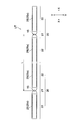
- FIG. 32 is a cross-sectional view (a view corresponding to a cross section taken along line BB in FIG. 31) showing a state where the light guide is fixed by the fixing member in the backlight unit according to the fifth embodiment of the present invention.
- the backlight unit by 5th Embodiment of this invention it is the side view which showed the state by which the light guide was fixed by the fixing member.
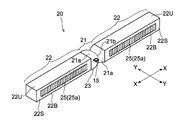
- FIG. 1 is a perspective view of a light guide according to a first embodiment of the present invention.
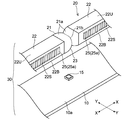
- FIG. 2 is a perspective view of a light source unit using the light guide according to the first embodiment of the present invention.
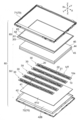
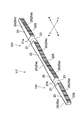
- FIG. 3 is an exploded perspective view of the liquid crystal display device including the backlight unit according to the first embodiment of the present invention.
- 4 to 14 are views for explaining a light guide and the like according to the first embodiment of the present invention.
- the liquid crystal display device 80 includes a liquid crystal display panel 60, a backlight unit 50 that supplies light to the liquid crystal display panel 60, and a pair opposed to each other with these interposed therebetween.
- Housing 70 front housing 71, back housing 72.
- the liquid crystal display device 80 is an example of the “display device” in the present invention
- the liquid crystal display panel 60 is an example of the “display panel” in the present invention.
- the backlight unit 50 is an example of the “lighting device” in the present invention.
- an active matrix substrate 61 including a switching element such as a TFT (Thin Film Transistor) and a counter substrate 62 facing the active matrix substrate 61 are bonded together with a sealing material (not shown). It is constituted by.
- liquid crystal (not shown) is injected into the gap between the substrates 61 and 62.
- a polarizing film 63 is attached to each of the light receiving surface side of the active matrix substrate 61 and the light emitting surface side of the counter substrate 62.
- the liquid crystal display panel 60 configured in this manner displays an image by utilizing a change in transmittance caused by the inclination of liquid crystal molecules.
- the backlight unit 50 is configured as a direct type, and includes a plurality of light source units 30, a reflection sheet 41, a backlight chassis 42, a diffusion plate 43, a prism sheet 44, and a lens sheet 45. is doing.
- the backlight unit 50 is disposed immediately below the liquid crystal display panel 60.
- the light source unit 30 constituting the backlight unit 50 includes a mounting substrate 10 and an LED (light emitting element, point light source) 15 as a light source mounted on the mounting substrate 10. And a light guide 20 provided on the mounting substrate 10.
- LED light emitting element, point light source
- the mounting substrate 10 is a plate-like and rectangular substrate, and has a configuration in which a plurality of electrodes (not shown) are arranged on the mounting surface 10a.
- the mounting substrate 10 is formed so as to extend in the X direction, and a plurality of the mounting substrates 10 are arranged in a direction intersecting the X direction (Y direction).
- the electrode formed on the mounting substrate 10 is a power supply terminal for a light source (light emitting element) such as the LED 15.
- a resist film (not shown) serving as a protective film may be formed on the mounting surface 10 a of the mounting substrate 10.
- the resist film is not particularly limited, but is preferably white having reflectivity. As described above, when a white resist film is formed on the mounting substrate 10 as the resist film, even if light is incident on the resist film, the light is reflected by the resist film and tends to go outside. For this reason, the cause of the light amount unevenness of the light absorption by the mounting substrate 10 is eliminated.
- the LED 15 is mounted on the electrode formed on the mounting substrate 10 and emits light upon receiving a current supply. Further, it is preferable that a plurality of LEDs 15 are mounted on the mounting substrate 10 in order to secure the light amount. However, in the drawings, only a part of the LEDs 15 are shown for convenience. Further, the plurality of LEDs 15 mounted on the mounting substrate 10 are configured to be able to individually control lighting.
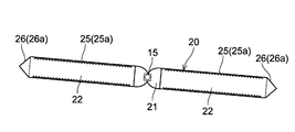
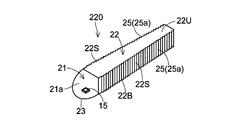
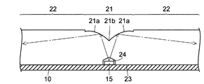
- the light guide 20 includes a light receiving portion 21 that receives light from the LED 15, and a wall portion 22 that is connected to the light receiving portion 21.
- the light guide 20 is made of, for example, a transparent resin material such as acrylic or polycarbonate that is allowed to travel while reflecting light inside.
- the light receiving portion 21 and the wall portion 22 are integrally formed of the above material.
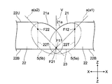
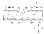
- the light receiving portion 21 of the light guide 20 has a curved surface shape as shown in FIGS. As shown in FIGS. 7 and 8, the curved surface shape is formed by using a part of the spheroid 5 obtained by rotating the ellipse. For this reason, the surface of the light receiving unit 21 has the same shape as the surface of the spheroid 5. That is, the light receiving unit 21 has a shape using a part of the spheroid 5.
- the surface (curved surface) of the light receiving unit 21 constituted by a part of the spheroid 5 is a reflecting surface 21 a that reflects the light incident on the light receiving unit 21.
- the light receiving portion 21 of the light guide 20 is configured such that light is incident from the bottom surface 23 side. That is, a light receiving surface is provided on the bottom surface 23 side of the light guide 20.
- the light guide 20 is configured to guide light incident from the bottom surface 23 side of the light receiving portion 21 to the wall portion 22 side by reflecting the light on the reflecting surface 21a.
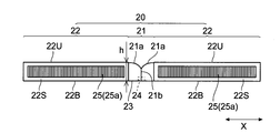
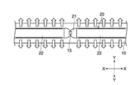
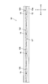
- the wall portion 22 of the light guide 20 is formed in a rod shape extending in one direction (X direction) as shown in FIGS. 4, 5, and 11. Specifically, the wall portion 22 is formed in a prismatic shape, for example.
- the width w (see FIG. 5) of the wall portion 22 can be, for example, about 3 mm to about 6 mm
- the height h (see FIG. 4) of the wall portion 22 is, for example, about 4 mm to It can be about 6 mm.
- the light receiving portion 21 is provided at the end of the wall portion 22 so that light incident on the light receiving portion 21 is guided from the end of the wall portion 22 into the wall portion 22.
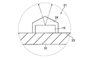
- the side wall 22S of the wall portion 22 has a rough surface (refractive index changing surface) 25 that changes the refraction angle of the traveling light.
- a prism processed surface 25a in which triangular prisms are arranged in the X direction on the side wall 22S can be cited.
- the rough surface 25 is configured to receive light at an angle less than the critical angle of the light guide 20.
- the rough surface 25 is an example of the “optical path changing processed surface” in the present invention.
- the example which provided the prism process surface 25a in the approximate center part of the thickness direction of the wall part 22 is shown.
- the light receiving unit 21 has a structure in which two spheroids 5 (5a and 5b) are combined.
- the two spheroids 5 are coupled such that the rotation axes a (a1 and a2) intersect with each other and the tip portions of the spheroids 5 overlap.
- the spheroid 5 has a rotation axis a (a1 and a2) as shown in FIG.
- the wall portion 22 is inclined with respect to the extending direction (X direction).
- the rotation axes a (a1 and a2) of the two spheroids 5 are respectively in the extending direction (X Direction).
- the two spheroids 5 have a focal point F11 (one focal point F11) of one spheroid 5a and a focal point F21 (one focal point F21) of the other spheroid 5b. Configured to match. If the other focal point corresponding to the focal point F11 is the focal point F12 and the other focal point corresponding to the focal point F21 is the focal point F22, the other focal points F12 and F22 of each spheroid 5 are the same focal point. It is located closer to the top surface of the light guide 20 (the top wall 22U of the wall portion 22) than F11 and F21.
- the two spheroids 5 are perpendicular to the extending direction (X direction) of the wall portion 22 through the vertical line V (the coincident focal points F11 and F21 (intersection of the rotation axes a1 and a2)) in FIG. It is configured to be symmetric with respect to V).
- a constriction line 21 b is formed at a joint portion of the two spheroids 5.
- the light guide 20 is configured such that the light receiving portion 21 is sandwiched between two wall portions 22. More specifically, one of the two spheroids 5 constituting the light receiving part 21 is attached to the end of one wall part 22 of the two wall parts 22 sandwiching the light receiving part 21, and the two spheroids 5 The other of the two wall portions 22 is attached to the end of the other wall portion 22.
- the other focal points F12 and F22 of the spheroid 5 are configured to coincide with the end portion (end surface 22T) of the wall portion 22 when viewed in a plan view.
- the other focal points F12 and F22 of the spheroid 5 do not necessarily coincide with the end portion (end surface 22T) of the wall portion 22, but these focal points F12 and F22 are not in the wall portion 22. It is preferable that the end portion (end surface 22T) coincides with the end portion of the wall portion 22 or the wall portion 22 side.
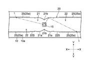
- the light receiving portion 21 in the light guide 20 is formed with a digging portion 24 dug inward from the bottom surface 23.
- the digging portion 24 is formed at a position that overlaps the focal points F11 and F21 (see FIG. 8) where the two spheroids 5 coincide when viewed two-dimensionally.
- the digging portion 24 houses an LED 15 as a light source.
- the light guide 20 is attached so that the light emitting point of the LED 15 and the focal point F11 (F21) of the spheroid 5 overlap as shown in FIG. It has been.
- the light receiving point that is the first location to receive the light from the LED 15 overlaps the focal point F11 (F21) of the spheroid 5.
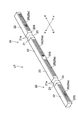
- a plurality of the light guides 20 are connected while being arranged in one direction to form the light guide unit UT.
- the plurality of light guides 20 are connected such that the end portions of the adjacent wall portions 22 face each other.
- the light guide unit UT may be configured by integrally connecting a plurality of light guides 20 or configured by arranging the plurality of light guides 20 separately. May be.
- a plurality of the light guide units UT are arranged in parallel. For this reason, a plurality of light source units 30 are also arranged in parallel.
- the light guide 20 (light guide unit UT) configured as described above covers the LED 15 on the mounting substrate 10 on which the LED 15 is mounted with the light receiving unit 21 (the LED 15 is in the digging unit 24).
- the light source unit 30 is configured by being attached so as to be positioned.
- the interval L between the LEDs 15 in the light source unit 30 (light guide unit UT) is, for example, about 54.5 mm.
- the reflection sheet 41 included in the backlight unit 50 is an optical member placed directly under the group of the mounting substrates 10 (light source units 30) arranged in parallel.
- the reflection sheet 41 directs the reflection surface 41U to the mounting substrate 10 side to reflect the light emitted from the light guide unit UT toward the mounting substrate 10 side without going to the diffusion plate 43 side, Guide to the diffuser plate 43.
- the backlight chassis 42 is, for example, a box-shaped member, and the reflection sheet 41 is laid on the bottom surface 42B, and further, the light source unit 30 is disposed thereon to accommodate them.
- the diffusion plate 43 is an optical sheet that overlaps the light source unit 30 and diffuses light emitted from the light source unit 30. That is, the diffusion plate 43 diffuses the planar light formed by overlapping the light from the plurality of light source units 30 and spreads the light over the entire area of the liquid crystal display panel 60.
- the diffusion plate 43 may be arranged so as to be in direct contact with the light guide 20 (light guide unit UT), but as shown in FIG. 9, the top surface of the light guide 20 (of the wall portion 22). It is preferably arranged in a state separated from the top wall 22U) by a predetermined distance S1 (for example, about 4 mm to about 6 mm). Thus, it becomes easy to suppress luminance unevenness by making a spatial distance above the light guide 20.
- the distance S2 from the mounting surface 10a of the mounting substrate 10 to the diffusion plate 43 is set to about 10 mm, for example.
- the prism sheet 44 is an optical sheet that overlaps the diffusion plate 43 as shown in FIG.
- triangular prisms extending in one direction (linear shape) are arranged in a direction intersecting with one direction in the sheet surface, and deflect the radiation characteristics of light from the diffusion plate 43.
- the lens sheet 45 is an optical sheet that overlaps the prism sheet 44.
- fine particles that refract and scatter light are dispersed in the lens sheet 45, and the light from the prism sheet 44 is not collected locally, and the difference in brightness (light intensity unevenness) is suppressed.
- the backlight unit 50 forms planar light by superimposing the light from the plurality of light source units 30, and the planar light is transmitted to the plurality of optical members 43 to 45.
- the liquid is passed through and supplied to the liquid crystal display panel 60.
- the non-light-emitting liquid crystal display panel 60 receives the light (backlight light) from the backlight unit 50 and improves the display function.
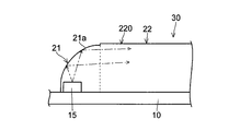
- the backlight unit 50 since the backlight unit 50 according to the first embodiment is configured as a direct type, the light source unit 30 is located directly below the diffusion plate 43. In other words, the light source unit 30 (LED 15) is arranged in an area corresponding to the display area of the liquid crystal display panel 60.
- the light emitted upward from the LED 15 reaches the reflecting surface 21 a of the light receiving unit 21 as indicated by the dashed line arrow.
- the reflection surface 21a is formed in a curved surface formed of a spheroid surface so that a light incident angle with respect to the reflection surface 21a is relatively large. For this reason, the reflection surface 21a of the light receiving unit 21 is easy to totally reflect the emitted light from the LED 15. Therefore, the light from the LED 15 that has reached the reflecting surface 21a of the light receiving unit 21 is totally reflected by the reflecting surface 21a and guided to the wall 22 side (see the dashed line arrow).
- the light receiving portion 21 of the light guide 20 has a structure in which two spheroids 5 (see FIG. 7) are combined, the light reaching one spheroid part. Is guided to one wall portion 22 side, and the light reaching the other spheroid part is guided to the other wall portion 22 side opposite to the one wall portion 22. That is, the light emitted from the LED 15 is guided in two directions (X1 direction and X2 direction) by the light receiving unit 21.
- the focal point F11 of one spheroid 5a and the focal point F21 of the other spheroid 5b coincide with each other, the light from the LED 15 is received.
- the light is reflected by the reflecting surface 21a of the portion 21 and easily passes near the other focal point F12 (F22). For this reason, the light emitted upward from the LED 15 is efficiently guided in the direction of the wall portion 22.
- the rough surface 25 such as the prism processing surface 25 a is formed on the side wall 22 ⁇ / b> S of the wall portion 22, the light traveling inside the wall portion 22 is transmitted by the rough surface 25. It is changed to an optical path suitable for external emission. That is, the light inside the light guide 20 is likely to enter the rough surface 25 at an angle less than the critical angle.
- the light traveling inside the wall portion 22 easily travels outside in various directions via the rough surface 25 of the side wall 22S. Therefore, the light incident on the light guide 20 from the LED 15 is radiated in the lateral direction from the side wall 22S of the wall 22 as shown in FIG. Note that white arrows in FIG. 11 indicate emitted light.
- the light control for each area is performed in which the brightness of each backlight area is adjusted in synchronization with the brightness of each area of the display image. ) Is realized.
- the light guide 20 (light guide unit UT) including the light receiving portion 21 and the wall portion 22, light emitted upward from the LED 15 is transmitted to the light guide 20.
- Light can be guided to the wall portion 22 by the light receiving portion 21 and light can be emitted from the side wall 22S of the wall portion 22 in the lateral direction. That is, by using the light guide 20, the light of the LED 15 emitted upward can be spread in the lateral direction. For this reason, even when the arrangement interval of the LEDs 15 is increased by reducing the number of the LEDs 15, high-quality planar light in which luminance unevenness is suppressed can be obtained.
- this planar light is generated by light emitted from the side wall 22S of the wall portion 22 in the lateral direction without being mainly composed of light from the top wall 22U of the wall portion 22, and thus diffused from the LED 15.
- luminance unevenness can be suppressed.
- the reflection surface 21a of the light receiving unit 21 is configured to have a curved surface, whereby the light incident on the light receiving unit 21 can be easily totally reflected by the reflection surface 21a. Thereby, since it is possible to make it difficult for light to leak from the light receiving unit 21, it is possible to suppress generation of bright spots due to light leakage.
- the material cost can be reduced by using the light guide 20 as described above as compared with the case of using a single light guide plate. Therefore, the cost can be reduced also by this.
- a single light guide plate it is necessary to change the manufacturing mold in accordance with the display area of the liquid crystal display panel 60.
- the manufacturing mold is used in the case of the light guide 20 (light guide unit UT).
- the display area of the liquid crystal display device 80 can be accommodated by changing the number of the light guides 20 (light guide units UT) without changing the mold. Therefore, by using this light guide 20 (light guide unit UT), it is possible to reduce the manufacturing cost of a mold and the like and to cope with various models.
- the direct-type backlight unit 50 is configured by using the light guide 20 described above, so that the direct-type backlight unit is compared with the edge-light type backlight unit. Since light loss can be reduced, a highly efficient backlight unit 50 can be obtained.
- the light receiving part 21 of the light guide 20 is formed by using a part of the spheroid 5 to facilitate total reflection of the light incident on the light receiving part 21. Therefore, light leakage can be effectively suppressed. That is, the light from the LED 15 can be guided to the wall portions 22 on both sides without going out upward or laterally. For this reason, since luminance unevenness directly above the LED 15 can be reduced, high-quality planar light can be easily obtained.
- the rotation axis a of the spheroid 5 is configured to be inclined with respect to the top wall 22U of the wall portion 22 (the extending direction of the wall portion 22 (X direction)) (the rotation ellipse with the rotation axis a inclined). If the reflecting surface 21a of the light receiving unit 21 is configured using a part of the body surface), the light incident on the light receiving unit 21 can be made to be more totally reflected, so that the light can be leaked more effectively. Can be suppressed.
- the light receiving portion 21 of the light guide 20 has a shape in which a plurality of (two) spheroids 5 are combined, the focal point F11 of one spheroid 5a, and the other
- the light receiving point of the light receiving unit 21 overlaps with one focus F11 (F21) included in the overlapping portion of the plurality of spheroids 5
- the light receiving point of the light receiving unit 21 overlaps with the focus F21 of the spheroid 5b.
- the light is likely to pass near the remaining focal point of the spheroid 5. For this reason, by comprising in this way, it can be made easy to reflect light toward the wall part 22 efficiently.
- the above-described light source unit 30 is disposed directly below the diffuser plate 43, and the LEDs 15 in the light source unit 30 are individually controlled to be turned on, so that dimming control for each area such as local dimming control ( Local light quantity control) can be performed.
- dimming control Local light quantity control
- the maximum value of the amount of emitted light as the backlight unit 50 can be changed depending on the number of the light source units 30.
- the direct-type backlight unit 50 is configured using the light source unit 30 having the light guide 20 (light guide unit UT).
- the backlight unit 50 can be realized.
- a thin liquid crystal display device 80 capable of performing dimming control for each region such as local dimming control can be realized at low cost.
- FIGS. 15 to 17 are views showing a light guide according to a second embodiment of the present invention.
- 18 and 19 are views showing a light guide unit in which light guides according to the second embodiment of the present invention are connected.
- FIG. 20 is a plan view of a light source unit using a light guide according to a second embodiment of the present invention.
- a light guide, a light guide unit, and a light source unit according to a second embodiment of the present invention will be described with reference to FIGS.
- symbol is attached
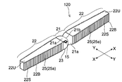
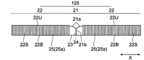
- the wall portion 22 is formed in a tapered shape as the distance from the light receiving portion 21 increases.
- the width (width in the Y direction) of the wall portion 22 of the light guide 120 is the largest at the end where the light receiving portion 21 is provided, and gradually decreases as the distance from the light receiving portion 21 increases. It is formed as follows.
- the width of the wall portion 22 is the smallest at the other end portion farthest from the light receiving portion 21.
- the height of the wall part 22 is constant over the whole length.
- the width w1 (see FIG. 19) of the end portion where the light receiving portion 21 is provided is, for example, about 4.5 mm, and the width w2 of the other end portion farthest from the light receiving portion 21 ( For example, it is about 2 mm.
- the rough surface 25 made of, for example, the same prism processing surface as that of the first embodiment is formed on the side wall 22S of the wall portion 22.
- the rough surface 25 is configured by forming a triangular prism having a length reaching the top wall 22U from the bottom wall 22B over almost the entire side wall 22S. And by comprising in this way, the light inside the light guide 120 becomes easy to radiate
- a plurality of the light guides 120 are connected while being arranged in one direction to form a light guide unit UT.
- a plurality of the light guide units UT are arranged in parallel.
- the plurality of light guides 120 are connected such that the end portions of the adjacent wall portions 22 face each other.
- the light guide unit UT may be configured by integrally connecting a plurality of light guides 120, or may be configured by arranging the plurality of light guides 120 separately. It may be.
- the light source 120 (light guide unit UT) comprised as mentioned above is provided on the mounting board
- a direct type backlight unit is configured.
- the wall portion 22 of the light guide body 120 has a tapered shape, so that light leakage from the distal end portion of the light guide body 120 can be suppressed.
- the light guide unit UT is configured by connecting such light guides 120 while being arranged in one direction, in the light guides 120 adjacent to each other, the one light guide 120 to the other light guide 120. It is possible to suppress the light from being guided. For this reason, generation
- a backlight unit is configured using the light source unit 30 or the like shown in the second embodiment, a low-cost, high-efficiency, and thin backlight unit can be easily realized.
- FIG. 21 and 22 are plan views showing a light source unit according to the third embodiment of the present invention.
- a light guide and a light source unit according to a third embodiment of the present invention will be described.
- symbol is attached
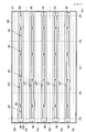
- a plurality of light guide bodies 120 shown in the second embodiment are connected while being arranged obliquely.
- the light guide unit UT is formed by connecting the some light guide 120 in this way, arranging in one direction in this way.
- the plurality of light guides 120 are connected so that the ends of the adjacent wall portions 22 face each other, whereas in the third embodiment, the light guide is guided.
- the plurality of light guides 120 are connected such that the ends of the adjacent wall portions 22 do not face each other.
- the light guide unit UT may be configured by arranging a plurality of light guides 120 separately, or as shown in FIG. 22, the plurality of light guides 120 are integrally connected. May be configured.
- the plurality of light guides 120 are arranged on the mounting substrate 10 while being obliquely shifted and arranged, so that the wall portion 22 is indicated by a one-dot chain line arrow in FIG. Even when light is emitted from the front end portion (end portion), it is possible to prevent the light from being guided to the wall portion 22 of the adjacent light guide 120. For this reason, when a plurality of light guides 120 are connected, it is possible to suppress the inconvenience that light from the adjacent LED 15 is guided into the light guide 120 and emitted from the light receiving unit 21. it can. Thereby, generation
- the wall portion 22 of the light guide 120 is tapered, light leakage from the tip portion of the light guide 120 (wall portion 22) is suppressed. However, even when configured in this way, light may leak from the tip (end) of the wall 22. Therefore, when connecting a plurality of light guides 120 while arranging them in one direction, as shown in the third embodiment, the end portions of the adjacent wall portions 22 are not opposed to each other. More preferably, the light guides 120 are connected to each other. And it can suppress that light is guided to the wall part 22 of the adjacent light guide 120 more effectively by comprising in this way.
- a backlight unit is configured using the light source unit 30 shown in the third embodiment, a low-cost, high-efficiency, and thin backlight unit with reduced brightness unevenness can be realized. .
- 23 and 24 are plan views showing a light source unit according to a modification of the third embodiment.
- 25 and 26 are diagrams showing an example in which a retroreflective structure is provided in a light source unit according to a modification of the third embodiment.
- a light source unit according to a modification of the third embodiment will be described with reference to FIGS.
- symbol is attached
- a plurality of light guides 20 shown in the first embodiment are connected while being arranged obliquely.
- the light guide unit UT is formed by connecting the some light guide 20 in this way, arranging in one direction in this way. That is, the modification of the third embodiment is different from the third embodiment in that the light guide body 20 of the first embodiment is used instead of the light guide body 120 of the second embodiment.
- the light guide unit UT may be configured by arranging a plurality of light guides 20 separately, or as shown in FIG. 24, the plurality of light guides 20 are integrally connected. May be configured.
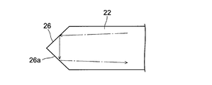
- the wall portion 22 of the light guide 20 is not tapered, light is likely to be emitted from the tip portion of the wall portion 22. . Therefore, as shown in FIG. 25, it is preferable to provide a retroreflective structure 26 at the tip of the wall portion 22. Specifically, it is preferable to form a quadrangular pyramid-shaped convex portion 26 a having retroreflectivity at the tip of the wall portion 22. In this way, if the pyramid-shaped convex part 26a is formed at the tip of the wall part 22, the light incident in the wall part 22 is incident in the direction of the incident light as shown by a one-dot chain line arrow in FIG. Is reflected. For this reason, it is possible to reduce leakage light from the light guide 20 (the front end portion of the wall portion 22). Therefore, if a backlight unit is configured using such a light guide 20 (light source unit 30), luminance unevenness is further reduced.
- the above-mentioned retroreflection structure 26 can also be provided in the front-end
- FIGS. 27 to 29 are views showing a light source unit according to a fourth embodiment of the present invention.
- a light guide and a light source unit according to a fourth embodiment of the present invention will be described with reference to FIGS.
- symbol is attached
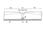
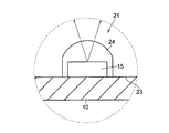
- the bounce-up processed surface 27 that guides light to the bottom wall 22B of the wall portion 22 of the light guide 20 so as to bounce up.
- a lens 28 for diffusing light is further formed on the top wall 22U of the wall portion 22 of the light guide 20.
- the flip-up processed surface 27 is, for example, a processed surface formed by arranging triangular prisms extending in one direction (linear) on the bottom wall 22B in the extending direction of the wall portion 22 (the same direction as the X direction). be able to.
- the lens 28 formed on the top wall 22U can have, for example, a shape in which two cylindrical curved surfaces are arranged.
- the example in which the flip-up processed surface 27 and the lens 28 are formed on the light guide 20 shown in the first embodiment is shown.
- the light guide 120 shown in the second embodiment Alternatively, the flip-up processed surface 27 and the lens 28 may be formed.
- FIGS. 30 to 34 are views for explaining a backlight unit according to a fifth embodiment of the present invention.
- a backlight unit according to a fifth embodiment of the present invention will be described with reference to FIGS.
- symbol is attached
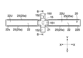
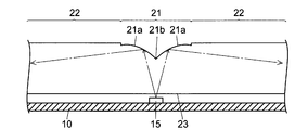
- a backlight unit is configured using the light source unit shown in the first embodiment. As shown in FIGS. 30 and 31, the light guide 20 constituting the light source unit is fixed by a fixing member 150.
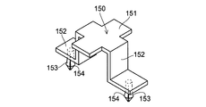
- the fixing member 150 is made of a material having excellent reflectivity, such as a white resin or a metal material. Further, as shown in FIG. 32, the fixing member 150 is in contact with the light guide 20, and a pressing portion 151 that presses the light guide 20 at the contact portion, and a leg portion that is connected to the pressing portion 151. 152. Further, a pin-shaped engagement piece 153 is provided on the leg portion 152 of the fixing member 150. As shown in FIG. 33, the engagement piece 153 is divided into, for example, a fork and a hook-shaped engagement portion 154 is formed at the tip. Further, as shown in FIG. 31, the pressing portion 151 of the fixing member 150 has, for example, a cross shape when viewed in a plan view. Accordingly, the pressing portion 151 covers the light receiving portion 21 and a part thereof comes into contact with a portion of the top wall 22U of the wall portion 22.
- a continuous through hole 40 through which the engagement piece 153 of the fixing member 150 is inserted is formed in the mounting substrate 10, the reflection sheet 41, and the backlight chassis 42.
- the fixing member 150 configured in this manner straddles the light receiving portion 21 of the light guide 20 so that the engagement piece 153 has a through hole 40 on the backlight chassis 42 side. Is inserted.
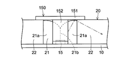
- the light guide 20 is fixed by the fixing member 150 when the engaging portion 154 of the engaging piece 153 engages with the peripheral edge of the through hole 40. At this time, the light receiving portion 21 of the light guide 20 is covered with the fixing member 150.
- the light guide 20 is fixed using such a fixing member 150, as shown in FIG. 34, for example, even when light leaks from the light receiving unit 21 due to misalignment of the LED 15, the light receiving unit 21 or the like.
- the light leakage can be blocked by the fixing member 150 covering the. Thereby, generation
- the light guide 20 can be easily fixed as compared with the case where the light guide 20 is fixed with an adhesive or the like.
- the fixing member 150 when light leakage from the light receiving unit 21 occurs by configuring the fixing member 150 from a material having high reflectance such as white resin or metal material, as shown by a one-dot chain line arrow in FIG. The light can be reflected by the fixing member 150 and easily guided to the wall portion 22 of the light guide 20.
- the example using the light source unit shown in the first embodiment has been described.
- a light source unit other than the first embodiment for example, the light source unit shown in the second to fourth embodiments.
- the same effect can be obtained even when using (). That is, for example, the light guide 120 as shown in the second embodiment can be fixed by the fixing member.
- (Sixth embodiment) 35 to 37 are views for explaining a light source unit according to a sixth embodiment of the present invention.
- a light source unit according to a sixth embodiment of the present invention will be described with reference to FIG. 7 and FIGS.
- symbol is attached
- the light guide 220 has a configuration including one wall portion 22 and one light receiving portion 21 as shown in FIGS. That is, in the sixth embodiment, the light receiving unit 21 of the light guide 220 is configured to guide the light from the LED 15 in one direction.
- the wall part 22 of the light guide 220 is, for example, the same wall part 22 as in the second embodiment, and the light receiving part 21 of the light guide 220 is, for example, one spheroid. 5 (see FIG. 7).
- the shape of the reflecting surface of the light receiving unit 21 is preferably a shape using the spheroid 5 as described above, but the light emitted upward from the LED 15 can be totally reflected as much as possible. It is more preferable if it is made into a shape.
- emitted upward from LED15 is reflected by the reflective surface 21a of the light-receiving part 21, as shown by the dashed-dotted arrow. It can be made to guide to the wall part 22 side. Since a rough surface 25 such as a prism processing surface is formed on the side wall 22S of the wall portion 22, the light guided into the wall portion 22 is changed to an optical path suitable for external emission by the rough surface 25. Radiated laterally.
- (Seventh embodiment) 38 and 39 are views illustrating a light guide according to a seventh embodiment of the present invention.
- 40 and 41 are views showing a light guide unit in which light guides according to a seventh embodiment of the present invention are connected.
- a light guide and a light guide unit according to a seventh embodiment of the present invention will be described with reference to FIGS. 1, 7, 8, 15, and 38 to 41.
- FIG. In addition, in each figure, the same code
- the light guide having two or one rod-like wall portions 22 has been described.
- the number of the wall portions 22 of the light guide may be more than two.
- the light guide 320 according to the seventh embodiment has a configuration including four rod-like wall portions 22.
- the four wall portions 22 are configured to extend radially with the light receiving portion 21 as the center.
- the two light guides 120 (see FIG. 15) shown in the second embodiment are combined to form a cross shape in plan view.
- the light receiving portion 21 of the light guide 320 has a structure in which four spheroids 5 (see FIGS. 7 and 8) corresponding to the four wall portions 22 are combined (coupled). Note that, as in the first and second embodiments, it is preferable that one of the focal points of the plurality (four) of spheroids coincide with each other.
- the light guide unit UT according to the seventh embodiment is constituted by connecting a plurality of the light guides 320 in a lattice shape.
- FIG. 40 and 41 an example in which the end surfaces of the wall portions 22 are connected to face each other is shown.
- the wall portions are connected by being shifted while being arranged obliquely.
- a plurality of light guides 320 may be coupled so that the ends of 22 do not face each other.
- the shape of the wall portion 22 of the light guide 320 is the same as the shape of the wall portion 22 of the light guide 120 shown in the second embodiment, but the shape is shown in the first embodiment.
- the shape of the wall portion 22 of the light guide 20 may be the same.
- (Eighth embodiment) 42 and 43 are views showing a light guide according to an eighth embodiment of the present invention.
- a light guide according to an eighth embodiment of the present invention will be described.
- symbol is attached
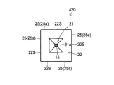
- the wall portion 22 of the light guide 420 is a piece that extends in the entire circumferential direction of the light receiving portion 21. It is formed in (chip shape).
- the wall portion 22 of the light guide body 420 is formed in a quadrangular shape when seen in a plan view, and the light receiving portion 21 is provided at the center thereof.
- the light receiving unit 21 can have a structure in which, for example, four spheroids are combined as shown in the seventh embodiment.
- light can be emitted from the side wall 22S without providing the rough surface 25 on the side wall 22S of the wall part 22, but the wall part 22 is used for the purpose of diffusing light.
- the rough surface 25 can also be provided on the side wall 22S.
- the rough surface 25 may not be provided on the side wall 22S of the wall portion 22.
- the light emitted upward from the LED 15 is reflected by the light receiving unit 21, guided to the wall 22 side, and emitted from the side wall 22 ⁇ / b> S of the wall 22 toward the outside. That is, even when such a light guide 420 is used, the light of the LED 15 radiated upward can be spread in the lateral direction.
- the light receiving part of the light guide has been illustrated as having a shape using a spheroid.
- the present invention is not limited to this, and is emitted upward from the LED. Any shape other than those described above may be used as long as it can guide light toward the wall.
- the light receiving part is formed using a spheroid, light from the LED can be easily totally reflected by the light receiving part, so that light leakage from the light receiving part is prevented. While suppressing, the light from the LED can be easily guided to the wall side. Therefore, the light receiving part of the light guide is preferably formed using a spheroid as described above. In this case, the shape and inclination (inclination angle of the rotation axis) of the spheroid can be set as appropriate.
- the rough surface made of the prism processing surface is formed on the side wall of the wall portion.
- the prism angle of the prism processing surface, the formation position of the rough surface, etc. can be changed as appropriate.
- the prism processing surface (rough surface) is provided at the substantially central portion in the thickness direction of the wall portion has been described. It can also be provided in the side region). In this case, since the distance from the prism processed surface (rough surface) to the diffusion plate is increased, the occurrence of luminance unevenness is effectively suppressed.
- a rough surface made of a prism processing surface is formed on the side wall of the wall portion.
- the present invention is not limited to this, and is made of a surface other than the prism processing surface.
- a rough surface made of a textured surface or a dot-type printed surface may be formed on the side wall of the wall portion.
- a rough surface other than the above may be formed on the side wall of the wall as long as it is a rough surface that changes the internal light to an optical path suitable for external emission.
- the present invention is not limited to this, and for example, as shown in FIG. It is good also as a structure which does not form a dug part in the bottom face 23.
- the bottom surface 23 of the light receiving unit 21 in the light guide may be a flat surface, and the light from the LED 15 may be configured to face the flat surface.
- the digging part is not formed in the bottom face 23 of the light-receiving part 21, the bottom face 23 of the light-receiving part 21 becomes a light-receiving surface.
- the digging part when the digging part is formed in the bottom face of the light receiving part, the digging part may be formed in a shape tapered from the bottom face 23 toward the inside as shown in FIGS. 45 and 46. . That is, the dug portion 24 may be formed to include a conical portion. Further, as shown in FIGS. 47 and 48, the digging portion 24 may be formed to include a hemispherical portion.
- each wall portion may be formed in the same shape or the like, or may be formed in a different shape or the like.
- the type of LED is not particularly limited.
- the LED may include a blue light emitting LED chip (light emitting chip) and a phosphor that receives light from the LED chip and fluoresces yellow light.
- a blue light emitting LED chip light emitting chip
- a phosphor that receives light from the LED chip and fluoresces yellow light.
- Such an LED generates white light using light from a blue light emitting LED chip and light emitted from a fluorescent light.
- the number of LED chips included in the LED is not particularly limited.
- the phosphor incorporated in the LED is not limited to a phosphor that emits yellow light.
- an LED includes a blue light emitting LED chip and a phosphor that emits green light and red light in response to light from the LED chip, and emits blue light and fluorescent light (green light) from the LED chip. , Red light) and white light can be used.
- the LED chip built in the LED is not limited to the one emitting blue light.
- the LED may include a red LED chip that emits red light, a blue LED chip that emits blue light, and a phosphor that emits green light by receiving light from the blue LED chip. With such an LED, white light can be generated by red light from the red LED chip, blue light from the blue LED chip, and green light that fluoresces.
- the LED may be an LED that does not contain any phosphor.
- a red LED chip that emits red light, a green LED chip that emits green light, and a blue LED chip that emits blue light are configured to generate white light by mixing light from all LED chips. Also good.
- the light emitted from the individual light guides is not limited to white light, and may be red light, green light, or blue light.
- the light guide that emits red light, green light, or blue light is as close as possible and is arranged so that white light can be generated by color mixing.
- a light guide that emits red light, a light guide that emits green light, and a light guide that emits blue light are preferably arranged adjacent to each other.
- the backlight unit includes the diffuser plate, the prism sheet, and the lens sheet as the optical member (optical sheet).
- the optical member optical sheet
- the optical member optical sheet
- the optical member can be appropriately changed (added or deleted) as necessary.
- the number of light guides (light guide unit, light source unit) included in the backlight unit can be changed as appropriate according to the type of the backlight unit.
- the present invention is not limited to this, and is for supplying light to a display panel.
- the present invention can be applied to all non-light emitting display devices including a backlight unit.
- a light source unit is configured using a light guide unit in which a plurality of light guides are connected.
- the present invention is not limited to this, and the light guide unit is configured. Instead, the light source unit may be configured using individual light guides.
- the shape of the mounting substrate may be a shape other than the shape shown in the above embodiment.
- the example in which the light guide (light guide unit, light source unit) is arranged so as to extend along the longitudinal direction (X direction) of the backlight unit has been described.
- the invention is not limited to this, and a light guide (light guide unit, light source unit) may be arranged so as to extend along the short direction (Y direction) of the backlight unit.
- tip part of the wall part of the light guide was formed in the quadrangular pyramid shape
- this invention is not restricted to this, For example, it is good also as a triangular pyramid shape or a prism shape. .
- tip part of the wall part which has the said shape is formed so that the vertex angle may become 90 degree
- the flip-up processed surface may be a processed surface other than the triangular prism (for example, a textured surface, a dot-type printed surface, etc.).
- the lens may have another lens shape.
- the fixing member that fixes the light guide may have a shape different from the shape shown in the above embodiment.
- a fixing member that can be fixed so as to cover the light receiving portion of the light guide is preferable because light leakage from the light receiving portion can be blocked.
- the present invention is not limited to this, and the number of wall portions of the light guide may be three or five. It may be the above.
- the light guide (wall part) showed the example formed in square shape seeing planarly, this invention is not limited to this, The wall part of a light guide is not shown.
- a triangular shape, a polygonal shape having five or more corners, a circular shape, or the like may be used.
Landscapes
- Physics & Mathematics (AREA)
- General Physics & Mathematics (AREA)
- Optics & Photonics (AREA)
- Nonlinear Science (AREA)
- Mathematical Physics (AREA)
- Chemical & Material Sciences (AREA)
- Crystallography & Structural Chemistry (AREA)
- Planar Illumination Modules (AREA)
Abstract
Provided is a light guiding body capable of offering higher efficiency and increased thinness, while facilitating minimized costs. The light guiding body comprises a light receiving unit (21) that receives light, and partition units (22) that are connected with the light receiving unit (21). The light receiving unit (21) of the light guiding body (20) further comprises a light guiding face on the underside (23) thereof, and includes curved surface reflector faces (21a) that reflect light toward the partition units (22). The partition units (22) of the light guiding body (20) further include lateral partitions (22S) that further comprise jagged faces (25) that redirect the interior light into light paths that are optimized for reflection to the exterior.
Description
本発明は、受けた光を導光させる導光体、導光体と光源とを有する光源ユニット、光源ユニットを含む照明装置および照明装置を備えた表示装置に関する。
The present invention relates to a light guide for guiding received light, a light source unit having a light guide and a light source, an illumination device including the light source unit, and a display device including the illumination device.
非発光型の液晶表示パネル(表示パネル)を搭載する液晶表示装置(表示装置)では、通常、その液晶表示パネルに対して、光を供給するバックライトユニット(照明装置)も搭載される。バックライトユニットは、面状の液晶表示パネル全域に対して行き渡るような面状光を生成するように構成されているのが好ましい。
In a liquid crystal display device (display device) equipped with a non-light emitting liquid crystal display panel (display panel), a backlight unit (illumination device) for supplying light is usually mounted on the liquid crystal display panel. The backlight unit is preferably configured to generate planar light that spreads over the entire area of the planar liquid crystal display panel.
ここで、液晶表示パネルに光を供給するバックライトユニットは、直下型とエッジライト型とに大別される。
Here, the backlight unit that supplies light to the liquid crystal display panel is roughly classified into a direct type and an edge light type.
直下型のバックライトユニットは、拡散板の下部に、光源となるLED(Light Emitting Diode)を複数配置した構成を有している。そして、複数のLEDからの光を拡散板によって拡散して外部に放出するように構成されている。このような直下型のバックライトユニットでは、複数のLEDを独立して制御することにより、表示画像の各領域の明暗と同期してバックライト各領域の明暗を調整する、いわゆる領域毎調光制御(ローカルディミング制御、エリアアクティブ制御等)を実現することができる。これにより液晶表示装置の大幅なコントラスト向上、および低消費電力化を図ることが可能となる。
The direct type backlight unit has a configuration in which a plurality of LEDs (Light Emitting Diodes) serving as light sources are arranged below the diffusion plate. And it is comprised so that the light from several LED may be spread | diffused with a diffusion plate, and it discharge | releases outside. In such a direct type backlight unit, a plurality of LEDs are independently controlled to adjust the brightness of each area of the backlight in synchronization with the brightness of each area of the display image. (Local dimming control, area active control, etc.) can be realized. As a result, the contrast of the liquid crystal display device can be greatly improved and the power consumption can be reduced.
しかしながら、直下型のバックライトユニットでは、光源部の輝度ムラ抑制のために、LEDと拡散板との距離を長くする必要がある。そのため、薄型化を図ることが困難であるという不都合がある。特に、コストを低減するためにLEDの数を減らした場合、LEDの配置間隔が広がるために輝度ムラが発生し易くなる。この場合、LEDと拡散板との距離をより長くする必要があるので、薄型化を図ることがより困難となる。したがって、従来の直下型のバックライトユニットでは、低コスト化と薄型化とを同時に実現するのが困難であるという問題点がある。
However, in the direct type backlight unit, it is necessary to lengthen the distance between the LED and the diffusion plate in order to suppress luminance unevenness of the light source unit. Therefore, there is an inconvenience that it is difficult to reduce the thickness. In particular, when the number of LEDs is reduced in order to reduce the cost, luminance unevenness is likely to occur because the LED arrangement interval is widened. In this case, since it is necessary to make the distance between the LED and the diffusion plate longer, it is more difficult to reduce the thickness. Therefore, the conventional direct type backlight unit has a problem that it is difficult to simultaneously realize a reduction in cost and a reduction in thickness.
一方、エッジライト型のバックライトユニットは、導光板の側面にLEDなどの光源が配置された構成を有しており、光源から出射された光が導光板の側面から導光板内部に入射されるとともに、入射された光は導光板内部で導光されて液晶表示パネル側に放出される。このようなエッジライト型のバックライトユニットでは、導光板の厚みを大きくしなくてもLEDからの光を上部に放出できるため、液晶表示装置の薄型化を容易に図ることができる。
On the other hand, the edge-light type backlight unit has a configuration in which a light source such as an LED is disposed on the side surface of the light guide plate, and light emitted from the light source enters the light guide plate from the side surface of the light guide plate. At the same time, the incident light is guided inside the light guide plate and emitted to the liquid crystal display panel side. In such an edge light type backlight unit, the light from the LED can be emitted upward without increasing the thickness of the light guide plate, so that the liquid crystal display device can be easily reduced in thickness.
また、従来、導光板の代わりに棒状の導光体(導光棒)を用いた、エッジライト型のバックライトユニットも提案されている(たとえば、特許文献1参照)。
Also, conventionally, an edge light type backlight unit using a rod-shaped light guide (light guide rod) instead of the light guide plate has been proposed (see, for example, Patent Document 1).
上記特許文献1には、複数の導光棒と、この導光棒の端面から光を入射する複数のLEDとを備えたエッジライト型のバックライトユニットが記載されている。このバックライトユニットでは、LED毎に対応させて導光棒が列状に配置されており、複数の導光棒は、端面から入射された光を多重反射させることで、光を自身の天面に導き外部に放出させる。
Patent Document 1 describes an edge-light type backlight unit that includes a plurality of light guide bars and a plurality of LEDs that receive light from the end faces of the light guide bars. In this backlight unit, light guide rods are arranged in a row corresponding to each LED, and the plurality of light guide rods reflect light incident from the end surface by multiple reflections, thereby allowing light to be reflected on its top surface. To be released to the outside.
しかしながら、エッジライト型のバックライトユニットは、直下型に比べて、薄型化に適しているものの、導光板や導光棒の端面に光を入射する際の入光ロスが大きいために、光の利用効率が低いという問題点がある。
However, although the edge light type backlight unit is suitable for thinning compared to the direct type, the light incident loss when light is incident on the end face of the light guide plate or light guide rod is large. There is a problem that usage efficiency is low.
また、導光板を用いたエッジライト型のバックライトユニットでは、画面全体での発光しかできないため、ローカルディミング制御等の領域毎調光制御を行うことができないという不都合もある。
Also, an edge light type backlight unit using a light guide plate can emit light only on the entire screen, and therefore there is a disadvantage that it is not possible to perform dimming control for each area such as local dimming control.
また、特許文献1に記載のバックライトユニットでは、LED毎に点灯制御を行うことが可能に構成されていれば、照明領域を線順次で走査させるラインスキャンができるものの、ローカルディミング制御等の領域毎調光制御(局所的な光量制御)を行うことはできないという問題点がある。
Further, in the backlight unit described in Patent Document 1, if it is configured to be able to perform lighting control for each LED, a line scan for scanning the illumination area in a line sequential manner can be performed, but an area for local dimming control or the like. There is a problem that it is not possible to perform dimming control (local light quantity control).
この発明は、上記のような課題を解決するためになされたものであり、この発明の1つの目的は、コストを低減しながら、高効率かつ薄型化を図ることが可能な導光体、光源ユニット、照明装置、および表示装置を提供することである。
The present invention has been made in order to solve the above-described problems, and one object of the present invention is to provide a light guide and a light source that can be thinned with high efficiency while reducing cost. It is to provide a unit, a lighting device, and a display device.
この発明のもう1つの目的は、局所的に光量制御を行うことが可能であり、かつ、高品質な面状光が得られる照明装置、および、その照明装置を搭載した表示装置を提供することである。
Another object of the present invention is to provide an illuminating device capable of locally controlling the amount of light and obtaining high-quality planar light, and a display device equipped with the illuminating device. It is.
上記目的を達成するために、この発明の第1の局面による導光体は、受光した光を内部で導光する導光体であって、光を受光する受光部と、受光部につながる壁部とを備えている。そして、上記受光部は、その底面側に受光面を有するとともに、壁部に向けて光を反射させる曲面状の反射面を含んでおり、上記壁部は、内部の光を、外部出射に適した光路に変更させる光路変更加工面を有する側壁を含んでいる。
In order to achieve the above object, a light guide according to a first aspect of the present invention is a light guide for guiding received light inside, and includes a light receiving portion for receiving light and a wall connected to the light receiving portion. Department. The light receiving portion has a light receiving surface on the bottom surface side thereof and includes a curved reflecting surface that reflects light toward the wall portion, and the wall portion is suitable for external emission of internal light. A side wall having an optical path changing surface to be changed to an optical path.
この第1の局面による導光体では、上記のように、曲面状の反射面を含む受光部を備えることによって、受光部の底面側から入射された光を、曲面状の反射面で反射させることにより、入射された光(受光した光)を受光部から壁部側に導くことができる。また、壁部の側面に光路変更加工面を設けることによって、導光体内部の光を外部出射に適した光路に変更することができる。そのため、壁部側に導かれた導光体内部の光を、壁部の側壁から外部に向けて出射させることができる。すなわち、壁部の側壁から、多量の光を外部に出射しやすくすることができる。
In the light guide according to the first aspect, as described above, by including the light receiving unit including the curved reflecting surface, the light incident from the bottom surface side of the light receiving unit is reflected by the curved reflecting surface. Thus, the incident light (received light) can be guided from the light receiving part to the wall part side. In addition, by providing an optical path changing processed surface on the side surface of the wall portion, the light inside the light guide can be changed to an optical path suitable for external emission. Therefore, the light inside the light guide guided to the wall portion side can be emitted outward from the side wall of the wall portion. That is, a large amount of light can be easily emitted to the outside from the side wall of the wall portion.
したがって、このような導光体を用いて直下型の照明装置を構成すれば、たとえば、光源の数を減らした場合でも、輝度ムラの抑制された高品質な面状光を得ることができる。その上、この面状光は、壁部の天面(天壁)からの光を主成分とすることなく、壁部の側壁からの光で生成されるので、たとえば、光源から拡散板までの距離を短くした場合でも、輝度ムラを抑制することができる。このため、コストを低減しながら、照明装置の薄型化を図ることができる。そのため、この導光体は、高品質な面状光を供給させたい照明装置に好適に用いることができる。
Therefore, if a direct-type illumination device is configured using such a light guide, for example, even when the number of light sources is reduced, high-quality planar light with reduced luminance unevenness can be obtained. In addition, this planar light is generated from light from the side wall of the wall portion without having light from the top surface (top wall) of the wall portion as a main component. Even when the distance is shortened, luminance unevenness can be suppressed. For this reason, it is possible to reduce the thickness of the lighting device while reducing the cost. Therefore, this light guide can be suitably used for an illumination device that wants to supply high-quality planar light.
また、第1の局面では、受光部の反射面を曲面状に構成することによって、受光部に入射された光を、反射面で全反射させやすくすることができる。これにより、受光部から光を漏れにくくすることができるので、光が漏れることに起因する輝点の発生を抑制することができる。
In the first aspect, the light incident on the light receiving part can be easily totally reflected on the reflecting surface by configuring the light reflecting part to have a curved surface. Thereby, it is possible to make it difficult for light to leak from the light receiving unit, and thus it is possible to suppress the occurrence of bright spots due to light leaking.
また、第1の局面では、上記のような導光体を用いることによって、一枚状の導光板を用いる場合に比べて、材料費を低減することができる。そのため、これによっても、コストを低減することができる。
Also, in the first aspect, by using the light guide as described above, the material cost can be reduced compared to the case of using a single light guide plate. Therefore, the cost can be reduced also by this.
さらに、第1の局面では、上記した導光体を用いて直下型の照明装置を構成すれば、エッジライト型の照明装置に比べて、入光ロスを低減することができるので、高効率の照明装置を得ることができる。
Furthermore, in the first aspect, if a direct-type illumination device is configured using the above-described light guide, light incident loss can be reduced as compared with an edge light illumination device. A lighting device can be obtained.
上記第1の局面による導光体において、好ましくは、受光部は、回転楕円体の一部を用いた形状を有している。このように構成すれば、受光部に入射された光を、効果的に全反射させることができるので、効果的に光の漏れを抑制することができる。
In the light guide according to the first aspect, preferably, the light receiving unit has a shape using a part of a spheroid. If comprised in this way, since the light which injected into the light-receiving part can be effectively totally reflected, the leakage of light can be suppressed effectively.
この場合において、回転楕円体の回転軸が、壁部の天壁に対して傾斜しているのが好ましい。このように、回転軸が傾斜した回転楕円体表面の一部を用いて、受光部の反射面を構成すれば、受光部に入射した光を、より効果的に全反射させることができるので、より効果的に光の漏れを抑制することができる。
In this case, it is preferable that the rotation axis of the spheroid is inclined with respect to the top wall of the wall portion. In this way, if the reflection surface of the light receiving unit is configured by using a part of the spheroid surface with the inclined rotation axis, the light incident on the light receiving unit can be more effectively totally reflected. Light leakage can be suppressed more effectively.
上記受光部が回転楕円体の一部を用いた形状を有する構成において、好ましくは、受光部は、複数の回転楕円体を結合させた形状を有しており、複数の回転楕円体における一方の焦点が、それぞれ、一致している。このように構成すれば、たとえば、受光部の受光点が、複数の回転楕円体の重なり合った部分に含まれる1つの焦点と重なると、光は、回転楕円体の残りの焦点付近を通過しやすくなる。このため、このように構成することにより、効率よく、壁部に向けて光を反射させやすくすることができる。
In the configuration in which the light receiving unit has a shape using a part of a spheroid, preferably, the light receiving unit has a shape obtained by combining a plurality of spheroids, The focal points are in agreement. With this configuration, for example, when the light receiving point of the light receiving unit overlaps with one focal point included in the overlapping portion of the plurality of spheroids, light easily passes near the remaining focal point of the spheroid. Become. For this reason, by comprising in this way, it can be made easy to reflect light toward a wall part efficiently.
この場合において、受光部は、2つの回転楕円体を結合させた形状を有しており、一方の回転楕円体の焦点と、他方の回転楕円体の焦点とが一致しているのが好ましい。
In this case, the light receiving section has a shape obtained by combining two spheroids, and it is preferable that the focal point of one spheroid coincides with the focal point of the other spheroid.
上記第1の局面による導光体において、好ましくは、壁部の底壁には、跳ね上げるように光を導く、跳ね上げ加工面が形成されており、壁部の天壁には、光を拡散させるレンズが形成されている。このように構成すれば、たとえば、壁部に進入してきた光のうち、底壁に到達した光は、跳ね上げ加工面によって跳ね上がるように導かれるため、壁部の天壁に向かいやすくすることができる。そして、跳ね上げられた光を、壁部の天壁に位置するレンズによって、拡散しつつ外部に出射させることができる。
In the light guide according to the first aspect described above, preferably, the bottom wall of the wall portion is formed with a bounce-up processed surface that guides light so as to bounce up, and light is applied to the top wall of the wall portion. A diffusing lens is formed. If comprised in this way, since the light which reached | attained the bottom wall among the light which approached into the wall part will be guide | induced so that it may jump up by the flip-up processed surface, it can make it easy to go to the ceiling wall of a wall part. it can. And the light bounced up can be radiate | emitted outside with the lens located in the ceiling wall of a wall part.
また、上記第1の局面による導光体において、上記壁部は、棒状に形成されていてもよい。この場合、導光体の受光部は、棒状に形成された壁部の端部に形成されているのが好ましい。
In the light guide according to the first aspect, the wall portion may be formed in a rod shape. In this case, the light receiving part of the light guide is preferably formed at the end of the wall part formed in a bar shape.
また、この場合において、受光部が、棒状に形成された2つの壁部によって挟まれており、受光部の反射面によって、受光した光を2方向に導くように構成されていればより好ましい。
In this case, it is more preferable that the light receiving portion is sandwiched between two wall portions formed in a rod shape and the received light is guided in two directions by the reflection surface of the light receiving portion.
上記壁部が棒状に形成された構成において、好ましくは、壁部の先端部には、入射された光をその入射した方向に反射させる再帰反射構造が形成されている。このように構成すれば、壁部の先端部から光が出射するのを抑制することができるので、壁部の先端部から光が出射することに起因する輝点の発生を抑制することができる。これにより、より高品質な面状光を得ることができる。
In the configuration in which the wall portion is formed in a rod shape, a retroreflective structure that reflects incident light in the incident direction is preferably formed at the tip of the wall portion. If comprised in this way, since it can suppress that a light radiate | emits from the front-end | tip part of a wall part, generation | occurrence | production of the bright spot resulting from light radiating | emitting from the front-end | tip part of a wall part can be suppressed. . Thereby, higher quality planar light can be obtained.
この場合において、好ましくは、上記再帰反射構造は、四角錐形状を有する凸部からなる。このように構成すれば、容易に、壁部の先端部から光が出射するのを抑制することができる。
In this case, preferably, the retroreflective structure includes a convex portion having a quadrangular pyramid shape. If comprised in this way, it can suppress that a light radiate | emits from the front-end | tip part of a wall part easily.
上記壁部が棒状に形成された構成において、棒状の壁部は、受光部から遠ざかるにしたがって先細りした形状を有しているのが好ましい。このように、棒状の壁部を先細り形状とすることによって、壁部の先端部からの光漏れを抑制することができる。
In the configuration in which the wall portion is formed in a rod shape, it is preferable that the rod-shaped wall portion has a tapered shape as the distance from the light receiving portion increases. Thus, the light leakage from the front-end | tip part of a wall part can be suppressed by making a rod-shaped wall part into a tapered shape.
上記第1の局面による導光体において、光路変更加工面は、プリズム加工された面、シボ加工された面、またはドット型印刷加工された面を含んでいるのが好ましい。このような加工面を側壁に形成することにより、容易に、導光体内部の光を、外部出射に適した光路に変更させることができる。
In the light guide according to the first aspect, it is preferable that the optical path changing processed surface includes a prism processed surface, a textured surface, or a dot-type printed surface. By forming such a processed surface on the side wall, the light inside the light guide can be easily changed to an optical path suitable for external emission.
上記第1の局面による導光体において、好ましくは、受光部は、その底面から内側に向けて掘られた掘り込み部を有しており、掘り込み部が、受光部にて受光する部分である。このように構成すれば、光源の位置合わせを容易とすることができる。
In the light guide according to the first aspect, preferably, the light receiving portion has a digging portion dug inward from the bottom surface, and the digging portion is a portion that receives light at the light receiving portion. is there. If comprised in this way, position alignment of a light source can be made easy.
この発明の第2の局面による光源ユニットは、上記第1の局面による導光体と、この導光体に対して光を供給する光源とを備えている。このように構成すれば、低コストで高効率な、薄型の照明装置を構成するのに適した光源ユニットを得ることができる。
A light source unit according to a second aspect of the present invention includes the light guide according to the first aspect and a light source that supplies light to the light guide. If comprised in this way, the light source unit suitable for comprising the thin illuminating device which is low-cost and highly efficient can be obtained.
上記第2の局面による光源ユニットにおいて、好ましくは、導光体の壁部は棒状に形成されており、導光体を複数個、斜めにずらして並べつつ連ねられている。このように構成すれば、互いに隣り合う導光体において、一方の導光体から他方の導光体に光が導光するのを抑制することができる。このため、一方の導光体から他方の導光体に光が導光することに起因する輝度ムラの発生を抑制することができる。これにより、高品質な面状光を得ることができる。
In the light source unit according to the second aspect, preferably, the wall portion of the light guide is formed in a rod shape, and a plurality of light guides are arranged while being shifted obliquely. If comprised in this way, in the light guides adjacent to each other, light can be prevented from being guided from one light guide to the other light guide. For this reason, generation | occurrence | production of the brightness nonuniformity resulting from light guiding from one light guide to the other light guide can be suppressed. Thereby, high quality planar light can be obtained.
なお、この場合、壁部の先端部に、四角錐形状を有する凸部を設けておけば、この四角錐形状の凸部によって、壁部の先端部からの漏れ光を軽減することができる。このため、このように構成しておけば、輝度ムラの発生をより効果的に抑制することができる。
In this case, if a convex portion having a quadrangular pyramid shape is provided at the distal end portion of the wall portion, the light leaking from the distal end portion of the wall portion can be reduced by the convex portion having the quadrangular pyramid shape. For this reason, if comprised in this way, generation | occurrence | production of brightness nonuniformity can be suppressed more effectively.
上記第2の局面による光源ユニットにおいて、光源は、発光素子であり、この発光素子の上方に、導光体の受光部が配されているのが好ましい。
In the light source unit according to the second aspect, it is preferable that the light source is a light emitting element, and the light receiving portion of the light guide is disposed above the light emitting element.
この発明の第3の局面による照明装置は、上記第2の局面による光源ユニットを備えた照明装置である。このように構成すれば、容易に、低コストで高効率な、薄型の照明装置を得ることができる。加えて、高品質な面状光を得ることができる。
An illumination device according to a third aspect of the present invention is an illumination device including the light source unit according to the second aspect. If comprised in this way, a low-cost and highly efficient thin illuminating device can be obtained easily. In addition, high-quality planar light can be obtained.
また、第3の局面では、上記第2の局面による光源ユニットを備えることによって、直下型の照明装置に構成することができる。そして、光源ユニットにおける光源を個別に点灯制御することにより、ローカルディミング制御等の領域毎調光制御(局所的な光量制御)を行うことができる。
Also, in the third aspect, by including the light source unit according to the second aspect, it is possible to configure a direct type illumination device. Then, lighting control for each region such as local dimming control (local light control) can be performed by individually controlling the light sources in the light source unit.
上記第3の局面による照明装置において、好ましくは、導光体を固定するための固定部材をさらに備えており、この固定部材によって、受光部の少なくとも一部が覆われている。このように構成すれば、受光部からの光漏れが生じた場合でも、固定部材によって光漏れを遮断することができる。これにより、輝度ムラの発生をさらに効果的に抑制することができる。
The lighting device according to the third aspect preferably further includes a fixing member for fixing the light guide, and at least a part of the light receiving unit is covered by the fixing member. If comprised in this way, even when the light leakage from a light-receiving part arises, light leakage can be interrupted | blocked by a fixing member. Thereby, generation | occurrence | production of brightness nonuniformity can be suppressed more effectively.
この場合において、好ましくは、固定部材は、白色樹脂から構成されている。このように構成すれば、白色樹脂は反射率が高いため、受光部からの光漏れが生じた場合に、漏れ光を固定部材で反射させて、導光体の壁部に導きやすくすることができる。
In this case, the fixing member is preferably made of a white resin. With this configuration, since the white resin has a high reflectance, when light leakage from the light receiving portion occurs, the leakage light can be reflected by the fixing member and easily guided to the wall portion of the light guide. it can.
上記第3の局面による照明装置において、好ましくは、導光体からの光を拡散する拡散板をさらに備え、拡散板が、光源および導光体の上方に配されている。このように構成すれば、低コストで薄型の直下型発光装置が容易に得られる。
The illumination device according to the third aspect preferably further includes a diffusion plate that diffuses light from the light guide, and the diffusion plate is disposed above the light source and the light guide. If comprised in this way, a low-cost and thin direct type light-emitting device can be obtained easily.
この発明の第4の局面による表示装置は、上記第3の局面による照明装置と、この照明装置からの光を受ける表示パネルとを備えた表示装置である。このように構成すれば、ローカルディミング制御等の領域毎調光制御(局所的な光量制御)を行うことが可能であり、かつ、低コストで薄型の表示装置を容易に得ることができる。
A display device according to a fourth aspect of the present invention is a display device including the illumination device according to the third aspect and a display panel that receives light from the illumination device. With this configuration, it is possible to perform dimming control for each region (local light amount control) such as local dimming control, and a thin display device can be easily obtained at low cost.
以上のように、本発明によれば、コストを低減しながら、高効率かつ薄型化を図ることが可能な導光体、光源ユニット、照明装置、および表示装置を容易に得ることができる。
As described above, according to the present invention, it is possible to easily obtain a light guide, a light source unit, a lighting device, and a display device that can be thinned with high efficiency while reducing costs.
また、本発明によれば、局所的に光量制御を行うことが可能であり、かつ、高品質な面状光が得られる照明装置、および、その照明装置を搭載した表示装置を容易に得ることができる。
Further, according to the present invention, it is possible to easily obtain a lighting device capable of locally controlling the amount of light and obtaining high-quality planar light, and a display device equipped with the lighting device. Can do.
以下、本発明を具体化した実施形態を図面に基づいて詳細に説明する。
DETAILED DESCRIPTION Hereinafter, embodiments embodying the present invention will be described in detail with reference to the drawings.
(第1実施形態)
図1は、本発明の第1実施形態による導光体の斜視図である。図2は、本発明の第1実施形態による導光体を用いた光源ユニットの斜視図である。図3は、本発明の第1実施形態によるバックライトユニットを備えた液晶表示装置の分解斜視図である。図4~図14は、本発明の第1実施形態による導光体等を説明するための図である。まず、図1~図14を参照して、本発明の第1実施形態による導光体、光源ユニット、バックライトユニットおよび液晶表示装置について説明する。 (First embodiment)
FIG. 1 is a perspective view of a light guide according to a first embodiment of the present invention. FIG. 2 is a perspective view of a light source unit using the light guide according to the first embodiment of the present invention. FIG. 3 is an exploded perspective view of the liquid crystal display device including the backlight unit according to the first embodiment of the present invention. 4 to 14 are views for explaining a light guide and the like according to the first embodiment of the present invention. First, a light guide, a light source unit, a backlight unit, and a liquid crystal display device according to a first embodiment of the present invention will be described with reference to FIGS.
第1実施形態による液晶表示装置80は、図3に示すように、液晶表示パネル60と、この液晶表示パネル60に対して光を供給するバックライトユニット50と、これらを挟んで互いに対向する一対のハウジング70(表ハウジング71、裏ハウジング72)とを備えている。なお、液晶表示装置80は、本発明の「表示装置」の一例であり、液晶表示パネル60は、本発明の「表示パネル」の一例である。また、バックライトユニット50は、本発明の「照明装置」の一例である。
As shown in FIG. 3, the liquid crystal display device 80 according to the first embodiment includes a liquid crystal display panel 60, a backlight unit 50 that supplies light to the liquid crystal display panel 60, and a pair opposed to each other with these interposed therebetween. Housing 70 (front housing 71, back housing 72). The liquid crystal display device 80 is an example of the “display device” in the present invention, and the liquid crystal display panel 60 is an example of the “display panel” in the present invention. The backlight unit 50 is an example of the “lighting device” in the present invention.
液晶表示パネル60は、たとえば、TFT(Thin Film Transistor)などのスイッチング素子を含むアクティブマトリックス基板61と、このアクティブマトリックス基板61に対向する対向基板62とをシール材(図示せず)で貼り合わせることによって構成されている。また、両基板61および62の隙間には、液晶(図示せず)が注入されている。そして、アクティブマトリックス基板61の受光面側および対向基板62の出射面側には、それぞれ、偏光フィルム63が取り付けられている。
In the liquid crystal display panel 60, for example, an active matrix substrate 61 including a switching element such as a TFT (Thin Film Transistor) and a counter substrate 62 facing the active matrix substrate 61 are bonded together with a sealing material (not shown). It is constituted by. In addition, liquid crystal (not shown) is injected into the gap between the substrates 61 and 62. A polarizing film 63 is attached to each of the light receiving surface side of the active matrix substrate 61 and the light emitting surface side of the counter substrate 62.
このように構成された液晶表示パネル60は、液晶分子の傾きに起因する透過率の変化を利用して、画像を表示する。
The liquid crystal display panel 60 configured in this manner displays an image by utilizing a change in transmittance caused by the inclination of liquid crystal molecules.
また、第1実施形態によるバックライトユニット50は直下型に構成されており、複数の光源ユニット30、反射シート41、バックライトシャーシ42、拡散板43、プリズムシート44、および、レンズシート45を有している。なお、上記バックライトユニット50は、液晶表示パネル60の直下に配置されている。
In addition, the backlight unit 50 according to the first embodiment is configured as a direct type, and includes a plurality of light source units 30, a reflection sheet 41, a backlight chassis 42, a diffusion plate 43, a prism sheet 44, and a lens sheet 45. is doing. The backlight unit 50 is disposed immediately below the liquid crystal display panel 60.
バックライトユニット50を構成する光源ユニット30は、図1および図2に示すように、実装基板10と、この実装基板10上に実装される、光源としてのLED(発光素子、点状光源)15と、実装基板10上に設けられた導光体20とを含む。
As shown in FIGS. 1 and 2, the light source unit 30 constituting the backlight unit 50 includes a mounting substrate 10 and an LED (light emitting element, point light source) 15 as a light source mounted on the mounting substrate 10. And a light guide 20 provided on the mounting substrate 10.
実装基板10は、図3および図14に示すように、板状かつ矩形状の基板であり、実装面10a上に、複数の電極(図示せず)が配列された構成を有している。この実装基板10は、X方向に延びるように形成されているとともに、X方向に対して交差する方向(Y方向)に複数配列されている。なお、実装基板10に形成された電極は、LED15のような光源(発光素子)に対する電力供給端子である。
As shown in FIGS. 3 and 14, the mounting substrate 10 is a plate-like and rectangular substrate, and has a configuration in which a plurality of electrodes (not shown) are arranged on the mounting surface 10a. The mounting substrate 10 is formed so as to extend in the X direction, and a plurality of the mounting substrates 10 are arranged in a direction intersecting the X direction (Y direction). The electrode formed on the mounting substrate 10 is a power supply terminal for a light source (light emitting element) such as the LED 15.
実装基板10における実装面10aには、保護膜となるレジスト膜(図示せず)が成膜されていてもよい。このレジスト膜は、特に限定されるものではないが、反射性を有する白色であると好ましい。このように、レジスト膜として、白色のレジスト膜を実装基板10に形成すれば、レジスト膜に光が入射したとしても、その光はレジスト膜で反射して外部に向かおうとする。このため、実装基板10による光の吸収という光量ムラの原因が解消される。
A resist film (not shown) serving as a protective film may be formed on the mounting surface 10 a of the mounting substrate 10. The resist film is not particularly limited, but is preferably white having reflectivity. As described above, when a white resist film is formed on the mounting substrate 10 as the resist film, even if light is incident on the resist film, the light is reflected by the resist film and tends to go outside. For this reason, the cause of the light amount unevenness of the light absorption by the mounting substrate 10 is eliminated.
LED15は、実装基板10に形成された電極上に実装されることで電流の供給を受けて光を発する。また、光量確保のために、複数のLED15が実装基板10に実装されていると好ましい。ただし、図面では便宜上、一部のLED15のみが示されているにすぎない。また、実装基板10に実装された複数のLED15は、個別に点灯制御を行うことが可能に構成されている。
The LED 15 is mounted on the electrode formed on the mounting substrate 10 and emits light upon receiving a current supply. Further, it is preferable that a plurality of LEDs 15 are mounted on the mounting substrate 10 in order to secure the light amount. However, in the drawings, only a part of the LEDs 15 are shown for convenience. Further, the plurality of LEDs 15 mounted on the mounting substrate 10 are configured to be able to individually control lighting.
導光体20は、図1および図2に示すように、LED15からの光を受光する受光部21と、受光部21とつながる壁部22とを備えている。この導光体20は、たとえば、アクリル、ポリカーボネートなどの、内部で光を反射させつつ進行させられる透明樹脂材料から構成されている。また、受光部21および壁部22は、上記材料によって一体的に形成されている。
As shown in FIGS. 1 and 2, the light guide 20 includes a light receiving portion 21 that receives light from the LED 15, and a wall portion 22 that is connected to the light receiving portion 21. The light guide 20 is made of, for example, a transparent resin material such as acrylic or polycarbonate that is allowed to travel while reflecting light inside. The light receiving portion 21 and the wall portion 22 are integrally formed of the above material.
導光体20の受光部21は、図4~図6に示すように、曲面状の表面形状を有している。この曲面状の表面形状は、図7および図8に示すように、楕円形を回転させることによって得られる回転楕円体5の一部を用いて形成されている。このため、受光部21の表面は、回転楕円体5の表面と同様の形状となっている。すなわち、上記受光部21は、回転楕円体5の一部を用いた形状を有している。そして、回転楕円体5の一部によって構成された受光部21の表面(曲面状の表面)が、受光部21に入射された光を反射させる反射面21aとなっている。
The light receiving portion 21 of the light guide 20 has a curved surface shape as shown in FIGS. As shown in FIGS. 7 and 8, the curved surface shape is formed by using a part of the spheroid 5 obtained by rotating the ellipse. For this reason, the surface of the light receiving unit 21 has the same shape as the surface of the spheroid 5. That is, the light receiving unit 21 has a shape using a part of the spheroid 5. The surface (curved surface) of the light receiving unit 21 constituted by a part of the spheroid 5 is a reflecting surface 21 a that reflects the light incident on the light receiving unit 21.
また、図9に示すように、導光体20の受光部21は、底面23側から光が入射されるように構成されている。すなわち、導光体20の底面23側に受光面が設けられている。そして、上記導光体20は、受光部21の底面23側から入射された光を反射面21aで反射させることにより壁部22側に導くように構成されている。
Further, as shown in FIG. 9, the light receiving portion 21 of the light guide 20 is configured such that light is incident from the bottom surface 23 side. That is, a light receiving surface is provided on the bottom surface 23 side of the light guide 20. The light guide 20 is configured to guide light incident from the bottom surface 23 side of the light receiving portion 21 to the wall portion 22 side by reflecting the light on the reflecting surface 21a.
導光体20の壁部22は、図4、図5および図11に示すように、一方向(X方向)に延びる棒状に形成されている。具体的には、この壁部22は、たとえば、角柱状に形成されている。なお、この場合、壁部22の幅w(図5参照)は、たとえば、約3mm~約6mmとすることができ、壁部22の高さh(図4参照)は、たとえば、約4mm~約6mmとすることができる。
The wall portion 22 of the light guide 20 is formed in a rod shape extending in one direction (X direction) as shown in FIGS. 4, 5, and 11. Specifically, the wall portion 22 is formed in a prismatic shape, for example. In this case, the width w (see FIG. 5) of the wall portion 22 can be, for example, about 3 mm to about 6 mm, and the height h (see FIG. 4) of the wall portion 22 is, for example, about 4 mm to It can be about 6 mm.
また、壁部22の端部には、上記受光部21が設けられており、受光部21に入射された光が壁部22の端部から壁部22内に導かれるように構成されている。さらに、壁部22の側壁22Sは、進行する光の屈折角を変える粗面(屈折率変更面)25を有している。粗面25の一例としては、図1および図2に示すように、三角プリズムを、側壁22SにてX方向に並べたプリズム加工面25aが挙げられる。そして、この粗面25は、導光体20の有する臨界角未満の角度で光を受光できるように構成されている。なお、上記粗面25は、本発明の「光路変更加工面」の一例である。また、この第1実施形態では、プリズム加工面25aを、壁部22の厚み方向の略中央部に設けた例を示している。
Further, the light receiving portion 21 is provided at the end of the wall portion 22 so that light incident on the light receiving portion 21 is guided from the end of the wall portion 22 into the wall portion 22. . Furthermore, the side wall 22S of the wall portion 22 has a rough surface (refractive index changing surface) 25 that changes the refraction angle of the traveling light. As an example of the rough surface 25, as shown in FIGS. 1 and 2, a prism processed surface 25a in which triangular prisms are arranged in the X direction on the side wall 22S can be cited. The rough surface 25 is configured to receive light at an angle less than the critical angle of the light guide 20. The rough surface 25 is an example of the “optical path changing processed surface” in the present invention. Moreover, in this 1st Embodiment, the example which provided the prism process surface 25a in the approximate center part of the thickness direction of the wall part 22 is shown.
ここで、第1実施形態では、図7および図8に示すように、上記受光部21は、2つの回転楕円体5(5aおよび5b)を結合させた構造を有している。この2つの回転楕円体5は、互いの回転軸a(a1およびa2)が交差するとともに、回転楕円体5の先端部分が重なるようにして結合されている。この際、回転楕円体5は、導光体20を側方から見た場合(図5のA1方向から見た場合)に、図7に示すように、その回転軸a(a1およびa2)が、壁部22の延び方向(X方向)に対して傾斜した状態となっている。なお、図8に示すように、導光体20を平面的に見た場合には、2つの回転楕円体5の回転軸a(a1およびa2)は、それぞれ、壁部22の延び方向(X方向)に沿った状態となっている。
Here, in the first embodiment, as shown in FIGS. 7 and 8, the light receiving unit 21 has a structure in which two spheroids 5 (5a and 5b) are combined. The two spheroids 5 are coupled such that the rotation axes a (a1 and a2) intersect with each other and the tip portions of the spheroids 5 overlap. In this case, when the light guide 20 is viewed from the side (when viewed from the direction A1 in FIG. 5), the spheroid 5 has a rotation axis a (a1 and a2) as shown in FIG. The wall portion 22 is inclined with respect to the extending direction (X direction). As shown in FIG. 8, when the light guide 20 is viewed in plan, the rotation axes a (a1 and a2) of the two spheroids 5 are respectively in the extending direction (X Direction).
また、第1実施形態では、2つの回転楕円体5は、一方の回転楕円体5aの焦点F11(一方の焦点F11)と、他方の回転楕円体5bの焦点F21(一方の焦点F21)とが一致するように構成されている。なお、焦点F11に対応するもう一方の焦点を焦点F12、焦点F21に対応するもう一方の焦点を焦点F22とすると、各回転楕円体5のもう一方の焦点F12およびF22は、一致している焦点F11およびF21よりも導光体20の天面(壁部22の天壁22U)側に位置している。
In the first embodiment, the two spheroids 5 have a focal point F11 (one focal point F11) of one spheroid 5a and a focal point F21 (one focal point F21) of the other spheroid 5b. Configured to match. If the other focal point corresponding to the focal point F11 is the focal point F12 and the other focal point corresponding to the focal point F21 is the focal point F22, the other focal points F12 and F22 of each spheroid 5 are the same focal point. It is located closer to the top surface of the light guide 20 (the top wall 22U of the wall portion 22) than F11 and F21.
また、2つの回転楕円体5は、図7の垂直線V(一致する焦点F11およびF21(回転軸a1とa2との交点)を通り、壁部22の延び方向(X方向)と垂直な線V)に対して対称となるように構成されている。なお、上記のように構成された受光部21には、2つの回転楕円体5の結合部分にくびれ線21bが形成されている。
Further, the two spheroids 5 are perpendicular to the extending direction (X direction) of the wall portion 22 through the vertical line V (the coincident focal points F11 and F21 (intersection of the rotation axes a1 and a2)) in FIG. It is configured to be symmetric with respect to V). In the light receiving unit 21 configured as described above, a constriction line 21 b is formed at a joint portion of the two spheroids 5.
さらに、上記導光体20は、その受光部21が2つの壁部22によって挟まれるように構成されている。詳説すると、受光部21を構成する2つの回転楕円体5の一方は、受光部21を挟む2つの壁部22の一方の壁部22の端部に取り付けられており、2つの回転楕円体5のもう一方は、2つの壁部22のもう一方の壁部22の端部に取り付けられている。
Furthermore, the light guide 20 is configured such that the light receiving portion 21 is sandwiched between two wall portions 22. More specifically, one of the two spheroids 5 constituting the light receiving part 21 is attached to the end of one wall part 22 of the two wall parts 22 sandwiching the light receiving part 21, and the two spheroids 5 The other of the two wall portions 22 is attached to the end of the other wall portion 22.
また、第1実施形態では、回転楕円体5のもう一方の焦点F12およびF22は、平面的に見た場合に、壁部22の端部(端面22T)と一致するように構成されている。なお、回転楕円体5のもう一方の焦点F12およびF22は、必ずしも、壁部22の端部(端面22T)と一致している必要はないが、これらの焦点F12およびF22は、壁部22の端部(端面22T)と一致しているか、壁部22の端部よりも壁部22側に位置しているのが好ましい。
In the first embodiment, the other focal points F12 and F22 of the spheroid 5 are configured to coincide with the end portion (end surface 22T) of the wall portion 22 when viewed in a plan view. The other focal points F12 and F22 of the spheroid 5 do not necessarily coincide with the end portion (end surface 22T) of the wall portion 22, but these focal points F12 and F22 are not in the wall portion 22. It is preferable that the end portion (end surface 22T) coincides with the end portion of the wall portion 22 or the wall portion 22 side.
また、図6および図9に示すように、導光体20における受光部21には、底面23から内側に向けて掘られた掘り込み部24が形成されている。この掘り込み部24は、平面的に見た場合に、2つの回転楕円体5の一致している焦点F11およびF21(図8参照)と重なる位置に形成されている。この掘り込み部24には、図9に示すように、光源としてのLED15が収納される。そして、LED15が収納された状態を平面的に見た場合、図10に示すように、LED15の発光点と回転楕円体5の焦点F11(F21)とが重なるように、導光体20が取り付けられている。この場合、LED15からの光を最初に受ける箇所である受光点が、回転楕円体5の焦点F11(F21)と重なる。
Further, as shown in FIGS. 6 and 9, the light receiving portion 21 in the light guide 20 is formed with a digging portion 24 dug inward from the bottom surface 23. The digging portion 24 is formed at a position that overlaps the focal points F11 and F21 (see FIG. 8) where the two spheroids 5 coincide when viewed two-dimensionally. As shown in FIG. 9, the digging portion 24 houses an LED 15 as a light source. When the state in which the LED 15 is housed is viewed in plan, the light guide 20 is attached so that the light emitting point of the LED 15 and the focal point F11 (F21) of the spheroid 5 overlap as shown in FIG. It has been. In this case, the light receiving point that is the first location to receive the light from the LED 15 overlaps the focal point F11 (F21) of the spheroid 5.
なお、上記導光体20は、図12~図14に示すように、複数個で、一方向に並べつつ連なることで、導光ユニットUTを形成する。具体的には、第1実施形態では、隣り合う壁部22の端部が対向するようにして、複数の導光体20が連結されている。また、上記導光ユニットUTは、複数の導光体20が一体的に連結されることによって構成されていてもよいし、複数の導光体20が別体で配列されることによって構成されていてもよい。また、図3および図14に示すように、上記導光ユニットUTは、複数個で並列されている。このため、光源ユニット30においても、複数個で並列されている。
Note that, as shown in FIGS. 12 to 14, a plurality of the light guides 20 are connected while being arranged in one direction to form the light guide unit UT. Specifically, in the first embodiment, the plurality of light guides 20 are connected such that the end portions of the adjacent wall portions 22 face each other. Further, the light guide unit UT may be configured by integrally connecting a plurality of light guides 20 or configured by arranging the plurality of light guides 20 separately. May be. As shown in FIGS. 3 and 14, a plurality of the light guide units UT are arranged in parallel. For this reason, a plurality of light source units 30 are also arranged in parallel.
そして、上記のように構成された導光体20(導光ユニットUT)が、LED15が実装された実装基板10上に、LED15を受光部21で覆うように(掘り込み部24内にLED15が位置するように)して取り付けられることにより、光源ユニット30が構成されている。なお、第1実施形態では、図13に示すように、光源ユニット30(導光ユニットUT)におけるLED15の間隔Lは、たとえば、約54.5mmとされている。
And the light guide 20 (light guide unit UT) configured as described above covers the LED 15 on the mounting substrate 10 on which the LED 15 is mounted with the light receiving unit 21 (the LED 15 is in the digging unit 24). The light source unit 30 is configured by being attached so as to be positioned. In the first embodiment, as shown in FIG. 13, the interval L between the LEDs 15 in the light source unit 30 (light guide unit UT) is, for example, about 54.5 mm.
また、図3に示すように、バックライトユニット50に含まれる反射シート41は、並列する実装基板10(光源ユニット30)の群の直下に置かれる光学部材である。この反射シート41は、反射面41Uを実装基板10側に向けることで、導光ユニットUTから出射した光のうち、拡散板43側に向かわずに、実装基板10側に向かう光を反射させ、拡散板43に導く。
Further, as shown in FIG. 3, the reflection sheet 41 included in the backlight unit 50 is an optical member placed directly under the group of the mounting substrates 10 (light source units 30) arranged in parallel. The reflection sheet 41 directs the reflection surface 41U to the mounting substrate 10 side to reflect the light emitted from the light guide unit UT toward the mounting substrate 10 side without going to the diffusion plate 43 side, Guide to the diffuser plate 43.
バックライトシャーシ42は、たとえば箱状の部材で、底面42Bに反射シート41を敷き、さらに、その上に、光源ユニット30を配置することで、それらを収容する。
The backlight chassis 42 is, for example, a box-shaped member, and the reflection sheet 41 is laid on the bottom surface 42B, and further, the light source unit 30 is disposed thereon to accommodate them.
拡散板43は、光源ユニット30に重なる光学シートであり、光源ユニット30から発せられる光を拡散させる。すなわち、拡散板43は、複数の光源ユニット30からの光を重ねることで形成される面状光を拡散させて、液晶表示パネル60の全域に光を行き渡らせる。なお、この拡散板43は、導光体20(導光ユニットUT)上に直接接するように配してもよいが、図9に示すように、導光体20の天面(壁部22の天壁22U)から所定の距離S1(たとえば、約4mm~約6mm)だけ離した状態で配されていると好ましい。このように、導光体20の上方に空間距離を空けることで、輝度ムラを抑制しやすくなる。また、第1実施形態では、実装基板10の実装面10aから拡散板43までの距離S2は、たとえば、約10mmに設定されている。
The diffusion plate 43 is an optical sheet that overlaps the light source unit 30 and diffuses light emitted from the light source unit 30. That is, the diffusion plate 43 diffuses the planar light formed by overlapping the light from the plurality of light source units 30 and spreads the light over the entire area of the liquid crystal display panel 60. The diffusion plate 43 may be arranged so as to be in direct contact with the light guide 20 (light guide unit UT), but as shown in FIG. 9, the top surface of the light guide 20 (of the wall portion 22). It is preferably arranged in a state separated from the top wall 22U) by a predetermined distance S1 (for example, about 4 mm to about 6 mm). Thus, it becomes easy to suppress luminance unevenness by making a spatial distance above the light guide 20. In the first embodiment, the distance S2 from the mounting surface 10a of the mounting substrate 10 to the diffusion plate 43 is set to about 10 mm, for example.
プリズムシート44は、図3に示すように、拡散板43に重なる光学シートである。このプリズムシート44は、一方向(線状)に延びるたとえば三角プリズムが、シート面内にて、一方向に交差する方向に並べられており、拡散板43からの光の放射特性を偏向させる。
The prism sheet 44 is an optical sheet that overlaps the diffusion plate 43 as shown in FIG. In the prism sheet 44, for example, triangular prisms extending in one direction (linear shape) are arranged in a direction intersecting with one direction in the sheet surface, and deflect the radiation characteristics of light from the diffusion plate 43.
レンズシート45は、プリズムシート44に重なる光学シートである。このレンズシート45は、光を屈折散乱させる微粒子が内部に分散されており、プリズムシート44からの光を、局所的に集光させることなく、明暗差(光量ムラ)を抑える。
The lens sheet 45 is an optical sheet that overlaps the prism sheet 44. In the lens sheet 45, fine particles that refract and scatter light are dispersed in the lens sheet 45, and the light from the prism sheet 44 is not collected locally, and the difference in brightness (light intensity unevenness) is suppressed.
上記のように構成された第1実施形態によるバックライトユニット50は、複数の光源ユニット30からの光を重ねることで面状光にし、その面状光を、複数枚の光学部材43~45に通過させて、液晶表示パネル60に供給する。これにより、非発光型の液晶表示パネル60は、バックライトユニット50からの光(バックライト光)を受光して表示機能を向上させる。
The backlight unit 50 according to the first embodiment configured as described above forms planar light by superimposing the light from the plurality of light source units 30, and the planar light is transmitted to the plurality of optical members 43 to 45. The liquid is passed through and supplied to the liquid crystal display panel 60. Thereby, the non-light-emitting liquid crystal display panel 60 receives the light (backlight light) from the backlight unit 50 and improves the display function.
なお、第1実施形態によるバックライトユニット50は、直下型に構成されているため、光源ユニット30は、拡散板43の直下に位置している。換言すると、光源ユニット30(LED15)が、液晶表示パネル60の表示領域に対応する領域に配置されている。
In addition, since the backlight unit 50 according to the first embodiment is configured as a direct type, the light source unit 30 is located directly below the diffusion plate 43. In other words, the light source unit 30 (LED 15) is arranged in an area corresponding to the display area of the liquid crystal display panel 60.
次に、図7、図9~図11、および図14を参照して、第1実施形態によるバックライトユニット50(特に、光源ユニット30)の作用について説明する。
Next, the operation of the backlight unit 50 (particularly, the light source unit 30) according to the first embodiment will be described with reference to FIG. 7, FIG. 9 to FIG. 11, and FIG.
まず、図9に示すように、LED15から上方に向けて出射された光は、一点鎖線の矢印で示すように、受光部21の反射面21aに到達する。この反射面21aは、回転楕円体表面からなる曲面状に形成されることによって、反射面21aに対する光の入射角が比較的大きくなるように構成されている。このため、受光部21の反射面21aは、LED15からの出射光を全反射しやすくなっている。そのため、受光部21の反射面21aに到達したLED15からの光は、その反射面21aで全反射されて、壁部22側に導かれる(一点鎖線矢印参照)。
First, as shown in FIG. 9, the light emitted upward from the LED 15 reaches the reflecting surface 21 a of the light receiving unit 21 as indicated by the dashed line arrow. The reflection surface 21a is formed in a curved surface formed of a spheroid surface so that a light incident angle with respect to the reflection surface 21a is relatively large. For this reason, the reflection surface 21a of the light receiving unit 21 is easy to totally reflect the emitted light from the LED 15. Therefore, the light from the LED 15 that has reached the reflecting surface 21a of the light receiving unit 21 is totally reflected by the reflecting surface 21a and guided to the wall 22 side (see the dashed line arrow).
また、第1実施形態では、導光体20の受光部21が2つの回転楕円体5(図7参照)を結合させた構造を有しているため、一方の回転楕円体部分に達した光は、一方の壁部22側に導かれ、もう一方の回転楕円体部分に達した光は、一方の壁部22とは反対側のもう一方の壁部22側に導かれる。すなわち、LED15から出射された光は、受光部21によって、2方向(X1方向およびX2方向)に導かれる。
In the first embodiment, since the light receiving portion 21 of the light guide 20 has a structure in which two spheroids 5 (see FIG. 7) are combined, the light reaching one spheroid part. Is guided to one wall portion 22 side, and the light reaching the other spheroid part is guided to the other wall portion 22 side opposite to the one wall portion 22. That is, the light emitted from the LED 15 is guided in two directions (X1 direction and X2 direction) by the light receiving unit 21.
さらに、図7に示したように、一方の回転楕円体5aの焦点F11と、もう一方の回転楕円体5bの焦点F21とが一致するように構成されているため、LED15からの光は、受光部21の反射面21aで反射されて、もう一方の焦点F12(F22)付近を通過しやすくなる。このため、LED15から上方に向けて出射された光は、効率よく、壁部22の方向に導かれる。
Further, as shown in FIG. 7, since the focal point F11 of one spheroid 5a and the focal point F21 of the other spheroid 5b coincide with each other, the light from the LED 15 is received. The light is reflected by the reflecting surface 21a of the portion 21 and easily passes near the other focal point F12 (F22). For this reason, the light emitted upward from the LED 15 is efficiently guided in the direction of the wall portion 22.
そして、図10に示すように、壁部22の側壁22Sには、プリズム加工面25aのような粗面25が形成されているため、壁部22内部を進行する光が、粗面25によって、外部出射に適した光路に変更される。すなわち、導光体20内部の光は、粗面25に対して、臨界角未満の角度で入射しやすくなる。
As shown in FIG. 10, since the rough surface 25 such as the prism processing surface 25 a is formed on the side wall 22 </ b> S of the wall portion 22, the light traveling inside the wall portion 22 is transmitted by the rough surface 25. It is changed to an optical path suitable for external emission. That is, the light inside the light guide 20 is likely to enter the rough surface 25 at an angle less than the critical angle.
そうすると、壁部22内部を進行していた光は、側壁22Sの粗面25を介して、様々な方向で外部に進行しやすくなる。そのため、LED15から導光体20に入射された光は、図11に示すように、壁部22の側壁22Sから、横方向に放射される。なお、図11の白矢印は、放射される光を示している。
Then, the light traveling inside the wall portion 22 easily travels outside in various directions via the rough surface 25 of the side wall 22S. Therefore, the light incident on the light guide 20 from the LED 15 is radiated in the lateral direction from the side wall 22S of the wall 22 as shown in FIG. Note that white arrows in FIG. 11 indicate emitted light.
そして、図14に示したように、このような導光体20(導光ユニットUT)を、複数個並べて配置することにより、導光体20からの光は高い度合いで混ざり合い、広面積で高品質な面状光が生成される。
Then, as shown in FIG. 14, by arranging a plurality of such light guides 20 (light guide units UT) side by side, the light from the light guide 20 is mixed to a high degree and has a large area. High quality planar light is generated.
また、光源ユニット30におけるLED15を個別に点灯制御することにより、たとえば、破線P1と破線P2とで囲まれた領域毎に、調光制御(局所的な光量制御)を行うことが可能となる。このため、このようなバックライトユニット50を用いることにより、表示画像の各領域の明暗と同期してバックライト各領域の明暗を調整する、領域毎調光制御(ローカルディミング制御、エリアアクティブ制御等)が実現される。
In addition, by individually controlling the lighting of the LEDs 15 in the light source unit 30, for example, it is possible to perform dimming control (local light amount control) for each region surrounded by the broken line P1 and the broken line P2. For this reason, by using such a backlight unit 50, the light control for each area (local dimming control, area active control, etc.) is performed in which the brightness of each backlight area is adjusted in synchronization with the brightness of each area of the display image. ) Is realized.
第1実施形態では、上記のように、受光部21と壁部22とを含む導光体20(導光ユニットUT)を用いることによって、LED15から上方に出射される光を導光体20の受光部21で壁部22に導き、この壁部22の側壁22Sから横方向に向けて光を放射させることができる。すなわち、上記導光体20を用いることにより、上方に向けて放射されたLED15の光を、横方向に広げることができる。このため、LED15の数を減らすことによりLED15の配置間隔が広がった場合でも、輝度ムラの抑制された高品質な面状光を得ることができる。その上、この面状光は、壁部22の天壁22Uからの光を主成分とすることなく、壁部22の側壁22Sから横方向に放射される光で生成されるので、LED15から拡散板43までの距離を短くした場合でも、輝度ムラを抑制することができる。このため、LED15の実装数を減らすことにより、コストを低減することができるとともに、その場合でも、バックライトユニット50の厚みが大きくなるのを抑制することができる。すなわち、コストを低減しながら、バックライトユニット50(液晶表示装置80)の薄型化を図ることができる。
In the first embodiment, as described above, by using the light guide 20 (light guide unit UT) including the light receiving portion 21 and the wall portion 22, light emitted upward from the LED 15 is transmitted to the light guide 20. Light can be guided to the wall portion 22 by the light receiving portion 21 and light can be emitted from the side wall 22S of the wall portion 22 in the lateral direction. That is, by using the light guide 20, the light of the LED 15 emitted upward can be spread in the lateral direction. For this reason, even when the arrangement interval of the LEDs 15 is increased by reducing the number of the LEDs 15, high-quality planar light in which luminance unevenness is suppressed can be obtained. In addition, this planar light is generated by light emitted from the side wall 22S of the wall portion 22 in the lateral direction without being mainly composed of light from the top wall 22U of the wall portion 22, and thus diffused from the LED 15. Even when the distance to the plate 43 is shortened, luminance unevenness can be suppressed. For this reason, it is possible to reduce the cost by reducing the number of mounted LEDs 15, and even in this case, it is possible to suppress an increase in the thickness of the backlight unit 50. That is, it is possible to reduce the thickness of the backlight unit 50 (the liquid crystal display device 80) while reducing the cost.
また、第1実施形態では、受光部21の反射面21aを曲面状に構成することによって、受光部21に入射された光を、反射面21aで全反射させやすくすることができる。これにより、受光部21から光を漏れにくくすることができるので、光が漏れることに起因する輝点の発生を抑制することができる。
In the first embodiment, the reflection surface 21a of the light receiving unit 21 is configured to have a curved surface, whereby the light incident on the light receiving unit 21 can be easily totally reflected by the reflection surface 21a. Thereby, since it is possible to make it difficult for light to leak from the light receiving unit 21, it is possible to suppress generation of bright spots due to light leakage.
また、第1実施形態では、上記のような導光体20を用いることによって、一枚状の導光板を用いる場合に比べて、材料費を低減することができる。そのため、これによっても、コストを低減することができる。また、1枚状の導光板の場合、液晶表示パネル60の表示面積に併せて、製造用金型の変更が必要になるが、導光体20(導光ユニットUT)の場合、製造用金型を変更することなく、導光体20(導光ユニットUT)の個数を変えることで、液晶表示装置80の表示面積に対応することができる。そのため、この導光体20(導光ユニットUT)を用いることにより、金型等の製造コストを低減することができるとともに、様々な機種に対応することができる。
In the first embodiment, the material cost can be reduced by using the light guide 20 as described above as compared with the case of using a single light guide plate. Therefore, the cost can be reduced also by this. In the case of a single light guide plate, it is necessary to change the manufacturing mold in accordance with the display area of the liquid crystal display panel 60. In the case of the light guide 20 (light guide unit UT), the manufacturing mold is used. The display area of the liquid crystal display device 80 can be accommodated by changing the number of the light guides 20 (light guide units UT) without changing the mold. Therefore, by using this light guide 20 (light guide unit UT), it is possible to reduce the manufacturing cost of a mold and the like and to cope with various models.
さらに、第1実施形態では、上記した導光体20を用いて直下型のバックライトユニット50を構成することにより、直下型のバックライトユニットは、エッジライト型のバックライトユニットに比べて、入光ロスを低減することができるので、高効率のバックライトユニット50を得ることができる。
Furthermore, in the first embodiment, the direct-type backlight unit 50 is configured by using the light guide 20 described above, so that the direct-type backlight unit is compared with the edge-light type backlight unit. Since light loss can be reduced, a highly efficient backlight unit 50 can be obtained.
また、第1実施形態では、導光体20の受光部21を、回転楕円体5の一部を用いて形成することにより、受光部21に入射された光を、全反射させやすくすることができるので、効果的に光の漏れを抑制することができる。すなわち、LED15からの光が上方向や横方向に抜けることなく、両側の壁部22に導光させることができる。このため、LED15の直上の輝度ムラを軽減することができるので、容易に、高品質な面状光を得ることができる。
In the first embodiment, the light receiving part 21 of the light guide 20 is formed by using a part of the spheroid 5 to facilitate total reflection of the light incident on the light receiving part 21. Therefore, light leakage can be effectively suppressed. That is, the light from the LED 15 can be guided to the wall portions 22 on both sides without going out upward or laterally. For this reason, since luminance unevenness directly above the LED 15 can be reduced, high-quality planar light can be easily obtained.
なお、回転楕円体5の回転軸aを、壁部22の天壁22U(壁部22の延び方向(X方向))に対して傾斜するように構成すれば(回転軸aが傾斜した回転楕円体表面の一部を用いて、受光部21の反射面21aを構成すれば)、受光部21に入射した光を、より全反射させやすくすることができるので、より効果的に光の漏れを抑制することができる。
If the rotation axis a of the spheroid 5 is configured to be inclined with respect to the top wall 22U of the wall portion 22 (the extending direction of the wall portion 22 (X direction)) (the rotation ellipse with the rotation axis a inclined). If the reflecting surface 21a of the light receiving unit 21 is configured using a part of the body surface), the light incident on the light receiving unit 21 can be made to be more totally reflected, so that the light can be leaked more effectively. Can be suppressed.
また、第1実施形態では、導光体20の受光部21を、複数(2つ)の回転楕円体5を結合させた形状とし、かつ、一方の回転楕円体5aの焦点F11と、もう一方の回転楕円体5bの焦点F21とが一致するように構成することによって、受光部21の受光点が、複数の回転楕円体5の重なり合った部分に含まれる1つの焦点F11(F21)と重なると、光は、回転楕円体5の残りの焦点付近を通過しやすくなる。このため、このように構成することにより、効率よく、壁部22に向けて光を反射させやすくすることができる。
In the first embodiment, the light receiving portion 21 of the light guide 20 has a shape in which a plurality of (two) spheroids 5 are combined, the focal point F11 of one spheroid 5a, and the other When the light receiving point of the light receiving unit 21 overlaps with one focus F11 (F21) included in the overlapping portion of the plurality of spheroids 5, the light receiving point of the light receiving unit 21 overlaps with the focus F21 of the spheroid 5b. The light is likely to pass near the remaining focal point of the spheroid 5. For this reason, by comprising in this way, it can be made easy to reflect light toward the wall part 22 efficiently.
また、第1実施形態では、上記した光源ユニット30を拡散板43の直下に配置することにより、光源ユニット30におけるLED15を個別に点灯制御することにより、ローカルディミング制御等の領域毎調光制御(局所的な光量制御)を行うことができる。その上、光源ユニット30の数によって、バックライトユニット50としての出射光量の最大値を変えることもできる。
In the first embodiment, the above-described light source unit 30 is disposed directly below the diffuser plate 43, and the LEDs 15 in the light source unit 30 are individually controlled to be turned on, so that dimming control for each area such as local dimming control ( Local light quantity control) can be performed. In addition, the maximum value of the amount of emitted light as the backlight unit 50 can be changed depending on the number of the light source units 30.
このように、第1実施形態では、導光体20(導光ユニットUT)を有する光源ユニット30を用いて直下型のバックライトユニット50を構成することにより、低コストで高効率、かつ、薄型のバックライトユニット50を実現することができる。また、このようなバックライトユニット50を用いれば、ローカルディミング制御等の領域毎調光制御を行うことができる薄型の液晶表示装置80を低コストで実現することができる。
As described above, in the first embodiment, the direct-type backlight unit 50 is configured using the light source unit 30 having the light guide 20 (light guide unit UT). The backlight unit 50 can be realized. In addition, when such a backlight unit 50 is used, a thin liquid crystal display device 80 capable of performing dimming control for each region such as local dimming control can be realized at low cost.
(第2実施形態)
図15~図17は、本発明の第2実施形態による導光体を示した図である。図18および図19は、本発明の第2実施形態による導光体を連ねた導光ユニットを示した図である。図20は、本発明の第2実施形態による導光体を用いた光源ユニットの平面図である。次に、図15~図20を参照して、本発明の第2実施形態による導光体、導光ユニットおよび光源ユニットについて説明する。なお、各図において、対応する構成要素には同一の符号を付すことにより、重複する説明は省略する。 (Second Embodiment)
15 to 17 are views showing a light guide according to a second embodiment of the present invention. 18 and 19 are views showing a light guide unit in which light guides according to the second embodiment of the present invention are connected. FIG. 20 is a plan view of a light source unit using a light guide according to a second embodiment of the present invention. Next, a light guide, a light guide unit, and a light source unit according to a second embodiment of the present invention will be described with reference to FIGS. In addition, in each figure, the same code | symbol is attached | subjected to a corresponding component, and the overlapping description is abbreviate | omitted.
この第2実施形態の導光体120では、図15および図16に示すように、その壁部22が、受光部21から遠ざかるにしたがって先細りした形状に形成されている。具体的には、導光体120の壁部22は、その幅(Y方向の幅)が、受光部21が設けられた端部で最も大きく、受光部21から遠ざかるにしたがい、徐々に小さくなるように形成されている。そして、受光部21から最も離れた他方の端部で、壁部22の幅が最も小さくなっている。
In the light guide body 120 of the second embodiment, as shown in FIGS. 15 and 16, the wall portion 22 is formed in a tapered shape as the distance from the light receiving portion 21 increases. Specifically, the width (width in the Y direction) of the wall portion 22 of the light guide 120 is the largest at the end where the light receiving portion 21 is provided, and gradually decreases as the distance from the light receiving portion 21 increases. It is formed as follows. The width of the wall portion 22 is the smallest at the other end portion farthest from the light receiving portion 21.
なお、図17に示すように、壁部22の高さは、全長に渡って一定となっている。また、壁部22において、受光部21が設けられた端部の幅w1(図19参照)は、たとえば、約4.5mmであり、受光部21から最も離れた他方の端部の幅w2(図19参照)は、たとえば、約2mmである。
In addition, as shown in FIG. 17, the height of the wall part 22 is constant over the whole length. Further, in the wall portion 22, the width w1 (see FIG. 19) of the end portion where the light receiving portion 21 is provided is, for example, about 4.5 mm, and the width w2 of the other end portion farthest from the light receiving portion 21 ( For example, it is about 2 mm.
また、第2実施形態では、壁部22の側壁22Sに、たとえば、上記第1実施形態と同様のプリズム加工面からなる粗面25が形成されている。この粗面25は、上記第1実施形態とは異なり、底壁22Bから天壁22Uに達する長さの三角プリズムが、側壁22Sのほぼ全面に形成されることによって構成されている。そして、このように構成することにより、導光体120内部の光が、壁部22の側壁22Sから外部に出射しやすくなっている。
Further, in the second embodiment, the rough surface 25 made of, for example, the same prism processing surface as that of the first embodiment is formed on the side wall 22S of the wall portion 22. Unlike the first embodiment, the rough surface 25 is configured by forming a triangular prism having a length reaching the top wall 22U from the bottom wall 22B over almost the entire side wall 22S. And by comprising in this way, the light inside the light guide 120 becomes easy to radiate | emit outside from the side wall 22S of the wall part 22. FIG.
また、図18および図19に示すように、この導光体120は、複数個で、一方向に並べつつ連なることで、導光ユニットUTを形成している。また、上記第1実施形態と同様、この導光ユニットUTは、複数個で並列する。
Further, as shown in FIGS. 18 and 19, a plurality of the light guides 120 are connected while being arranged in one direction to form a light guide unit UT. As in the first embodiment, a plurality of the light guide units UT are arranged in parallel.
なお、この第2実施形態においても、隣り合う壁部22の端部が対向するようにして、複数の導光体120が連結されている。この際、上記導光ユニットUTは、複数の導光体120が一体的に連結されることによって構成されていてもよいし、複数の導光体120が別体で配列されることによって構成されていてもよい。
In the second embodiment as well, the plurality of light guides 120 are connected such that the end portions of the adjacent wall portions 22 face each other. At this time, the light guide unit UT may be configured by integrally connecting a plurality of light guides 120, or may be configured by arranging the plurality of light guides 120 separately. It may be.
そして、図20に示すように、上記のように構成された導光体120(導光ユニットUT)が、LED15が実装された実装基板10上に設けられることにより、光源ユニット30が構成されている。なお、第2実施形態においても、光源ユニット30(導光ユニットUT)におけるLED15の間隔Lは、たとえば、約54.5mmとされている。
And as shown in FIG. 20, the light source 120 (light guide unit UT) comprised as mentioned above is provided on the mounting board | substrate 10 with which LED15 was mounted, and the light source unit 30 is comprised. Yes. Also in the second embodiment, the distance L between the LEDs 15 in the light source unit 30 (light guide unit UT) is, for example, about 54.5 mm.
また、上記光源ユニット30を用いることにより、直下型のバックライトユニットが構成される。
Also, by using the light source unit 30, a direct type backlight unit is configured.
第2実施形態のその他の構成は、上記第1実施形態と同様である。
Other configurations of the second embodiment are the same as those of the first embodiment.
第2実施形態では、上記のように、導光体120の壁部22を、先細り形状とすることによって、導光体120の先端部からの光漏れを抑制することができる。このため、このような導光体120を一方向に並べつつ連ねることによって導光ユニットUTを構成した場合、互いに隣り合う導光体120において、一方の導光体120から他方の導光体120に光が導光するのを抑制することができる。このため、一方の導光体120から他方の導光体120に光が導光することに起因する輝度ムラの発生を抑制することができる。これにより、高品質な面状光を得ることができる。
In the second embodiment, as described above, the wall portion 22 of the light guide body 120 has a tapered shape, so that light leakage from the distal end portion of the light guide body 120 can be suppressed. For this reason, when the light guide unit UT is configured by connecting such light guides 120 while being arranged in one direction, in the light guides 120 adjacent to each other, the one light guide 120 to the other light guide 120. It is possible to suppress the light from being guided. For this reason, generation | occurrence | production of the brightness nonuniformity resulting from light guiding from one light guide 120 to the other light guide 120 can be suppressed. Thereby, high quality planar light can be obtained.
また、第2実施形態で示した光源ユニット30等を用いてバックライトユニットを構成すれば、容易に、低コストで高効率、かつ、薄型のバックライトユニットを実現することができる。
Further, if a backlight unit is configured using the light source unit 30 or the like shown in the second embodiment, a low-cost, high-efficiency, and thin backlight unit can be easily realized.
第2実施形態のその他の効果は、上記第1実施形態と同様である。
Other effects of the second embodiment are the same as those of the first embodiment.
(第3実施形態)
図21および図22は、本発明の第3実施形態による光源ユニットを示した平面図である。次に、図21および図22を参照して、本発明の第3実施形態による導光体および光源ユニットについて説明する。なお、各図において、対応する構成要素には同一の符号を付すことにより、重複する説明は省略する。 (Third embodiment)
21 and 22 are plan views showing a light source unit according to the third embodiment of the present invention. Next, with reference to FIG. 21 and FIG. 22, a light guide and a light source unit according to a third embodiment of the present invention will be described. In addition, in each figure, the same code | symbol is attached | subjected to a corresponding component, and the overlapping description is abbreviate | omitted.
この第3実施形態による光源ユニットでは、図21に示すように、上記第2実施形態で示した導光体120が、複数個、斜めにずらして並べつつ連ねられている。そして、このように、複数個の導光体120が、一方向に並べつつ連なることで、導光ユニットUTが形成されている。
In the light source unit according to the third embodiment, as shown in FIG. 21, a plurality of light guide bodies 120 shown in the second embodiment are connected while being arranged obliquely. And the light guide unit UT is formed by connecting the some light guide 120 in this way, arranging in one direction in this way.
詳説すると、上記第2実施形態では、隣り合う壁部22の端部同士が対向するようにして、複数の導光体120が連結されていたのに対し、この第3実施形態では、導光体120を斜めにずらすことにより、隣り合う壁部22の端部同士が対向しないようにして、複数の導光体120が連結されている。
More specifically, in the second embodiment, the plurality of light guides 120 are connected so that the ends of the adjacent wall portions 22 face each other, whereas in the third embodiment, the light guide is guided. By shifting the body 120 obliquely, the plurality of light guides 120 are connected such that the ends of the adjacent wall portions 22 do not face each other.
なお、上記導光ユニットUTは、複数の導光体120が別体で配列されることによって構成されていてもよいし、図22に示すように、複数の導光体120が一体的に連結されることによって構成されていてもよい。
Note that the light guide unit UT may be configured by arranging a plurality of light guides 120 separately, or as shown in FIG. 22, the plurality of light guides 120 are integrally connected. May be configured.
第3実施形態では、上記のように、実装基板10上に、複数個の導光体120を、斜めにずらして並べつつ連ねることにより、図22の一点鎖線矢印で示すように、壁部22の先端部(端部)から光が出射した場合でも、その光が隣り合う導光体120の壁部22に導光するのを抑制することができる。このため、複数の導光体120を連結した場合に、隣のLED15からの光が導光体120内に導光されて受光部21から出射されてしまうという不都合が生じるのを抑制することができる。これにより、隣のLED15からの光が受光部21から出射されることに起因する輝度ムラの発生を抑制することができる。
In the third embodiment, as described above, the plurality of light guides 120 are arranged on the mounting substrate 10 while being obliquely shifted and arranged, so that the wall portion 22 is indicated by a one-dot chain line arrow in FIG. Even when light is emitted from the front end portion (end portion), it is possible to prevent the light from being guided to the wall portion 22 of the adjacent light guide 120. For this reason, when a plurality of light guides 120 are connected, it is possible to suppress the inconvenience that light from the adjacent LED 15 is guided into the light guide 120 and emitted from the light receiving unit 21. it can. Thereby, generation | occurrence | production of the brightness nonuniformity resulting from the light from the adjacent LED15 being radiate | emitted from the light-receiving part 21 can be suppressed.
なお、上記第2実施形態では、導光体120の壁部22を先細り形状としたために、導光体120(壁部22)の先端部からの光漏れが抑制されている。しかしながら、このように構成した場合でも、壁部22の先端部(端部)から光が漏れるおそれがある。そのため、複数個の導光体120を、一方向に並べつつ連ねる場合には、第3実施形態で示したように、隣り合う壁部22の端部同士が対向しないようにして、複数個の導光体120を連結するように構成するとより好ましい。そして、このように構成することによって、より効果的に、隣り合う導光体120の壁部22に光が導光されるのを抑制することができる。
In the second embodiment, since the wall portion 22 of the light guide 120 is tapered, light leakage from the tip portion of the light guide 120 (wall portion 22) is suppressed. However, even when configured in this way, light may leak from the tip (end) of the wall 22. Therefore, when connecting a plurality of light guides 120 while arranging them in one direction, as shown in the third embodiment, the end portions of the adjacent wall portions 22 are not opposed to each other. More preferably, the light guides 120 are connected to each other. And it can suppress that light is guided to the wall part 22 of the adjacent light guide 120 more effectively by comprising in this way.
また、第3実施形態で示した光源ユニット30を用いてバックライトユニットを構成すれば、より輝度ムラが抑制された、低コストで高効率、かつ、薄型のバックライトユニットを実現することができる。
In addition, if a backlight unit is configured using the light source unit 30 shown in the third embodiment, a low-cost, high-efficiency, and thin backlight unit with reduced brightness unevenness can be realized. .
図23および図24は、第3実施形態の変形例による光源ユニットを示した平面図である。図25および図26は、第3実施形態の変形例による光源ユニットに再帰反射構造を設けた例を示した図である。次に、図23~図26を参照して、第3実施形態の変形例による光源ユニットについて説明する。なお、各図において、対応する構成要素には同一の符号を付すことにより、重複する説明は省略する。
23 and 24 are plan views showing a light source unit according to a modification of the third embodiment. 25 and 26 are diagrams showing an example in which a retroreflective structure is provided in a light source unit according to a modification of the third embodiment. Next, a light source unit according to a modification of the third embodiment will be described with reference to FIGS. In addition, in each figure, the same code | symbol is attached | subjected to a corresponding component, and the overlapping description is abbreviate | omitted.
この第3実施形態の変形例では、図23に示すように、上記第1実施形態で示した導光体20が、複数個、斜めにずらして並べつつ連ねられている。そして、このように、複数個の導光体20が、一方向に並べつつ連なることで、導光ユニットUTが形成されている。すなわち、第3実施形態の変形例では、第2実施形態の導光体120に代えて、第1実施形態の導光体20を用いている点で、上記第3実施形態とは異なる。
In the modification of the third embodiment, as shown in FIG. 23, a plurality of light guides 20 shown in the first embodiment are connected while being arranged obliquely. And the light guide unit UT is formed by connecting the some light guide 20 in this way, arranging in one direction in this way. That is, the modification of the third embodiment is different from the third embodiment in that the light guide body 20 of the first embodiment is used instead of the light guide body 120 of the second embodiment.
なお、上記導光ユニットUTは、複数の導光体20が別体で配列されることによって構成されていてもよいし、図24に示すように、複数の導光体20が一体的に連結されることによって構成されていてもよい。
The light guide unit UT may be configured by arranging a plurality of light guides 20 separately, or as shown in FIG. 24, the plurality of light guides 20 are integrally connected. May be configured.
ここで、第3実施形態の変形例では、上記第3実施形態とは異なり、導光体20の壁部22が先細り形状となっていないため、壁部22の先端部から光が出射しやすい。そのため、図25に示すように、壁部22の先端部に、再帰反射構造26を設けるのが好ましい。具体的には、壁部22の先端部に、再帰反射性を有する四角錐状の凸部26aを形成するのが好ましい。このように、壁部22の先端部に四角錐状の凸部26aを形成すれば、壁部22内に入射された光は、図26の一点鎖線矢印で示すように、その入射された方向に反射される。そのため、導光体20(壁部22の先端部)からの漏れ光を低減することが可能となる。したがって、このような導光体20(光源ユニット30)を用いてバックライトユニットを構成すれば、輝度ムラがさらに低減される。
Here, in the modification of the third embodiment, unlike the third embodiment, since the wall portion 22 of the light guide 20 is not tapered, light is likely to be emitted from the tip portion of the wall portion 22. . Therefore, as shown in FIG. 25, it is preferable to provide a retroreflective structure 26 at the tip of the wall portion 22. Specifically, it is preferable to form a quadrangular pyramid-shaped convex portion 26 a having retroreflectivity at the tip of the wall portion 22. In this way, if the pyramid-shaped convex part 26a is formed at the tip of the wall part 22, the light incident in the wall part 22 is incident in the direction of the incident light as shown by a one-dot chain line arrow in FIG. Is reflected. For this reason, it is possible to reduce leakage light from the light guide 20 (the front end portion of the wall portion 22). Therefore, if a backlight unit is configured using such a light guide 20 (light source unit 30), luminance unevenness is further reduced.
なお、上記した再帰反射構造26は、第3実施形態で示した導光体120の先端部に設けることもできる。
In addition, the above-mentioned retroreflection structure 26 can also be provided in the front-end | tip part of the light guide 120 shown in 3rd Embodiment.
(第4実施形態)
図27~図29は、本発明の第4実施形態による光源ユニットを示した図である。次に、図27~図29を参照して、本発明の第4実施形態による導光体および光源ユニットについて説明する。なお、各図において、対応する構成要素には同一の符号を付すことにより、重複する説明は省略する。 (Fourth embodiment)
27 to 29 are views showing a light source unit according to a fourth embodiment of the present invention. Next, a light guide and a light source unit according to a fourth embodiment of the present invention will be described with reference to FIGS. In addition, in each figure, the same code | symbol is attached | subjected to a corresponding component, and the overlapping description is abbreviate | omitted.
この第4実施形態では、図27に示すように、上記第1実施形態の構成において、導光体20の壁部22の底壁22Bに、跳ね上げるように光を導く、跳ね上げ加工面27がさらに形成されている。また、導光体20の壁部22の天壁22Uには、光を拡散させるレンズ28がさらに形成されている。
In the fourth embodiment, as shown in FIG. 27, in the configuration of the first embodiment, the bounce-up processed surface 27 that guides light to the bottom wall 22B of the wall portion 22 of the light guide 20 so as to bounce up. Is further formed. Further, a lens 28 for diffusing light is further formed on the top wall 22U of the wall portion 22 of the light guide 20.
なお、跳ね上げ加工面27は、たとえば、一方向(線状)に延びる三角プリズムを、壁部22の延び方向(X方向と同方向)に、底壁22Bに並べて形成される加工面とすることができる。また、天壁22Uに形成されるレンズ28は、たとえば、シリンドリカル状の曲面を2つ並べた形状とすることができる。
The flip-up processed surface 27 is, for example, a processed surface formed by arranging triangular prisms extending in one direction (linear) on the bottom wall 22B in the extending direction of the wall portion 22 (the same direction as the X direction). be able to. In addition, the lens 28 formed on the top wall 22U can have, for example, a shape in which two cylindrical curved surfaces are arranged.
このような導光体20であれば、たとえば、図28に示すように、受光部21の反射面21aで全反射した光が壁部22の底壁22Bに到達したような場合であっても、その光は、一点鎖線矢印で示すように、底壁22Bの跳ね上げ加工面27によって天壁22Uの方へと導かれる。そして、この光が天壁22Uに達すると、天壁22Uに位置するレンズ28によって、光が種々方向に屈折進行させられる。これにより、図29の一点鎖線矢印で示すように、導光体20からの光は、導光体20を中心にして、放射される。
With such a light guide 20, for example, as shown in FIG. 28, even when the light totally reflected by the reflection surface 21 a of the light receiving portion 21 reaches the bottom wall 22 </ b> B of the wall portion 22. The light is guided toward the top wall 22U by the flip-up processed surface 27 of the bottom wall 22B, as indicated by a one-dot chain line arrow. When this light reaches the top wall 22U, the light is refracted in various directions by the lens 28 located on the top wall 22U. Thereby, as indicated by a one-dot chain line arrow in FIG. 29, light from the light guide 20 is emitted around the light guide 20.
なお、第4実施形態では、第1実施形態で示した導光体20に、跳ね上げ加工面27およびレンズ28を形成した例を示したが、第2実施形態で示した導光体120に、跳ね上げ加工面27およびレンズ28が形成された構成とすることもできる。
In the fourth embodiment, the example in which the flip-up processed surface 27 and the lens 28 are formed on the light guide 20 shown in the first embodiment is shown. However, the light guide 120 shown in the second embodiment Alternatively, the flip-up processed surface 27 and the lens 28 may be formed.
(第5実施形態)
図30~図34は、本発明の第5実施形態によるバックライトユニットを説明するための図である。次に、図30~図34を参照して、本発明の第5実施形態によるバックライトユニットについて説明する。なお、各図において、対応する構成要素には同一の符号を付すことにより、重複する説明は省略する。 (Fifth embodiment)
30 to 34 are views for explaining a backlight unit according to a fifth embodiment of the present invention. Next, a backlight unit according to a fifth embodiment of the present invention will be described with reference to FIGS. In addition, in each figure, the same code | symbol is attached | subjected to a corresponding component, and the overlapping description is abbreviate | omitted.
この第5実施形態では、たとえば、上記第1実施形態で示した光源ユニットを用いてバックライトユニットが構成されている。そして、図30および図31に示すように、光源ユニットを構成する導光体20が、固定部材150によって固定されている。
In the fifth embodiment, for example, a backlight unit is configured using the light source unit shown in the first embodiment. As shown in FIGS. 30 and 31, the light guide 20 constituting the light source unit is fixed by a fixing member 150.
この固定部材150は、反射性に優れた材料である、たとえば、白色樹脂や金属材料などから構成されている。また、図32に示すように、固定部材150は、導光体20と当接するとともに、その当接部分で導光体20を押圧する押圧部151と、この押圧部151と連接された脚部152とを備えている。また、固定部材150の脚部152には、ピン状の係合片153が設けられている。この係合片153は、図33に示すように、たとえば、二股に分かれており、その先端部分に鈎状の係合部154が形成されている。また、固定部材150の押圧部151は、図31に示すように、平面的に見て、たとえば、十字形状を有している。これにより、上記押圧部151は、受光部21を覆うとともに、その一部が、壁部22の天壁22Uの一部と当接される。
The fixing member 150 is made of a material having excellent reflectivity, such as a white resin or a metal material. Further, as shown in FIG. 32, the fixing member 150 is in contact with the light guide 20, and a pressing portion 151 that presses the light guide 20 at the contact portion, and a leg portion that is connected to the pressing portion 151. 152. Further, a pin-shaped engagement piece 153 is provided on the leg portion 152 of the fixing member 150. As shown in FIG. 33, the engagement piece 153 is divided into, for example, a fork and a hook-shaped engagement portion 154 is formed at the tip. Further, as shown in FIG. 31, the pressing portion 151 of the fixing member 150 has, for example, a cross shape when viewed in a plan view. Accordingly, the pressing portion 151 covers the light receiving portion 21 and a part thereof comes into contact with a portion of the top wall 22U of the wall portion 22.
一方、実装基板10、反射シート41およびバックライトシャーシ42には、固定部材150の係合片153が挿通される連続した貫通孔40が形成されている。
Meanwhile, a continuous through hole 40 through which the engagement piece 153 of the fixing member 150 is inserted is formed in the mounting substrate 10, the reflection sheet 41, and the backlight chassis 42.
このように構成された固定部材150は、図30および図33に示すように、導光体20の受光部21を跨ぐようにして、その係合片153がバックライトシャーシ42側の貫通孔40に挿通されている。そして、係合片153の係合部154が、貫通孔40の周縁部と係合することにより、この固定部材150によって、導光体20が固定されている。このとき、導光体20の受光部21は、固定部材150によって覆われた状態となっている。
As shown in FIGS. 30 and 33, the fixing member 150 configured in this manner straddles the light receiving portion 21 of the light guide 20 so that the engagement piece 153 has a through hole 40 on the backlight chassis 42 side. Is inserted. The light guide 20 is fixed by the fixing member 150 when the engaging portion 154 of the engaging piece 153 engages with the peripheral edge of the through hole 40. At this time, the light receiving portion 21 of the light guide 20 is covered with the fixing member 150.
また、このような固定部材150を用いて導光体20を固定すれば、図34に示すように、たとえば、LED15の位置ずれなどによって、受光部21から光が漏れた場合でも、受光部21を覆う固定部材150で光漏れを遮断することができる。これにより、輝度ムラの発生をさらに効果的に抑制することができる。
Further, if the light guide 20 is fixed using such a fixing member 150, as shown in FIG. 34, for example, even when light leaks from the light receiving unit 21 due to misalignment of the LED 15, the light receiving unit 21 or the like. The light leakage can be blocked by the fixing member 150 covering the. Thereby, generation | occurrence | production of brightness nonuniformity can be suppressed more effectively.
また、このような固定部材150を用いれば、接着剤などで導光体20を固定する場合に比べて、簡易に導光体20を固定することができる。
Further, when such a fixing member 150 is used, the light guide 20 can be easily fixed as compared with the case where the light guide 20 is fixed with an adhesive or the like.
さらに、固定部材150を、白色樹脂や金属材料などの反射率が高い材料から構成することにより、受光部21からの光漏れが生じた場合に、図34の一点鎖線矢印で示すように、漏れ光を固定部材150で反射させて、導光体20の壁部22に導きやすくすることができる。
Furthermore, when light leakage from the light receiving unit 21 occurs by configuring the fixing member 150 from a material having high reflectance such as white resin or metal material, as shown by a one-dot chain line arrow in FIG. The light can be reflected by the fixing member 150 and easily guided to the wall portion 22 of the light guide 20.
なお、第5実施形態では、上記第1実施形態で示した光源ユニットを用いた例について説明したが、第1実施形態以外の光源ユニット(たとえば、第2~第4実施形態で示した光源ユニット)を用いた場合でも同様の効果を得ることができる。すなわち、たとえば、第2実施形態で示したような導光体120を固定部材で固定することもできる。
In the fifth embodiment, the example using the light source unit shown in the first embodiment has been described. However, a light source unit other than the first embodiment (for example, the light source unit shown in the second to fourth embodiments). The same effect can be obtained even when using (). That is, for example, the light guide 120 as shown in the second embodiment can be fixed by the fixing member.
(第6実施形態)
図35~図37は、本発明の第6実施形態による光源ユニットを説明するための図である。次に、図7および図35~図37を参照して、本発明の第6実施形態による光源ユニットについて説明する。なお、各図において、対応する構成要素には同一の符号を付すことにより、重複する説明は省略する。 (Sixth embodiment)
35 to 37 are views for explaining a light source unit according to a sixth embodiment of the present invention. Next, a light source unit according to a sixth embodiment of the present invention will be described with reference to FIG. 7 and FIGS. In addition, in each figure, the same code | symbol is attached | subjected to a corresponding component, and the overlapping description is abbreviate | omitted.
この第6実施形態による導光体220は、図35および図36に示すように、1つの壁部22と1つの受光部21とを備えた構成となっている。すなわち、この第6実施形態では、導光体220の受光部21が、LED15からの光を一方向に導くように構成されている。
The light guide 220 according to the sixth embodiment has a configuration including one wall portion 22 and one light receiving portion 21 as shown in FIGS. That is, in the sixth embodiment, the light receiving unit 21 of the light guide 220 is configured to guide the light from the LED 15 in one direction.
具体的には、導光体220の壁部22は、たとえば、上記第2実施形態と同様の壁部22となっており、導光体220の受光部21は、たとえば、1つの回転楕円体5(図7参照)を用いた形状となっている。
Specifically, the wall part 22 of the light guide 220 is, for example, the same wall part 22 as in the second embodiment, and the light receiving part 21 of the light guide 220 is, for example, one spheroid. 5 (see FIG. 7).
なお、受光部21の反射面の形状は、上記のように、回転楕円体5を用いた形状とするのが好ましいが、LED15から上方に放射される光を出来る限り全反射させることが可能な形状とされているとより好ましい。
The shape of the reflecting surface of the light receiving unit 21 is preferably a shape using the spheroid 5 as described above, but the light emitted upward from the LED 15 can be totally reflected as much as possible. It is more preferable if it is made into a shape.
そして、このような導光体220を用いた場合には、図37に示すように、LED15から上方に放射される光を、一点鎖線矢印で示すように、受光部21の反射面21aで反射させて、壁部22側に導くことができる。壁部22の側壁22Sには、プリズム加工面のような粗面25が形成されているため、壁部22内に導かれた光は、粗面25によって、外部出射に適した光路に変更され、横方向に放射される。
And when such a light guide 220 is used, as shown in FIG. 37, the light radiated | emitted upward from LED15 is reflected by the reflective surface 21a of the light-receiving part 21, as shown by the dashed-dotted arrow. It can be made to guide to the wall part 22 side. Since a rough surface 25 such as a prism processing surface is formed on the side wall 22S of the wall portion 22, the light guided into the wall portion 22 is changed to an optical path suitable for external emission by the rough surface 25. Radiated laterally.
(第7実施形態)
図38および図39は、本発明の第7実施形態による導光体を示した図である。図40および図41は、本発明の第7実施形態による導光体を連ねた導光ユニットを示した図である。次に、図1、図7、図8、図15および図38~図41を参照して、本発明の第7実施形態による導光体および導光ユニットについて説明する。なお、各図において、対応する構成要素には同一の符号を付すことにより、重複する説明は省略する。 (Seventh embodiment)
38 and 39 are views illustrating a light guide according to a seventh embodiment of the present invention. 40 and 41 are views showing a light guide unit in which light guides according to a seventh embodiment of the present invention are connected. Next, a light guide and a light guide unit according to a seventh embodiment of the present invention will be described with reference to FIGS. 1, 7, 8, 15, and 38 to 41. FIG. In addition, in each figure, the same code | symbol is attached | subjected to a corresponding component, and the overlapping description is abbreviate | omitted.
上記した第1~第6実施形態では、棒状の壁部22を2つ、または、1つ備えた導光体について説明したが、導光体の壁部22は、2つより多くてもよい。たとえば、この第7実施形態による導光体320は、棒状の壁部22を4つ備えた構成となっている。具体的には、図38および図39に示すように、第7実施形態では、受光部21を中心として、4つの壁部22が放射状に延びるように構成されている。より具体的には、上記第2実施形態で示した導光体120(図15参照)を2つ組み合わせることにより、平面的に見て、十字形状となるように構成されている。
In the first to sixth embodiments described above, the light guide having two or one rod-like wall portions 22 has been described. However, the number of the wall portions 22 of the light guide may be more than two. . For example, the light guide 320 according to the seventh embodiment has a configuration including four rod-like wall portions 22. Specifically, as shown in FIGS. 38 and 39, in the seventh embodiment, the four wall portions 22 are configured to extend radially with the light receiving portion 21 as the center. More specifically, the two light guides 120 (see FIG. 15) shown in the second embodiment are combined to form a cross shape in plan view.
また、導光体320の受光部21は、4つの壁部22に対応する4つの回転楕円体5(図7および図8参照)を組み合わせた(結合させた)構造となっている。なお、上記第1および第2実施形態と同様、複数(4つ)の回転楕円体における一方の焦点が、それぞれ、一致するように構成されているのが好ましい。
Further, the light receiving portion 21 of the light guide 320 has a structure in which four spheroids 5 (see FIGS. 7 and 8) corresponding to the four wall portions 22 are combined (coupled). Note that, as in the first and second embodiments, it is preferable that one of the focal points of the plurality (four) of spheroids coincide with each other.
また、図40および図41に示すように、第7実施形態による導光ユニットUTは、上記導光体320を複数個、格子状に連ねることによって構成されている。
As shown in FIGS. 40 and 41, the light guide unit UT according to the seventh embodiment is constituted by connecting a plurality of the light guides 320 in a lattice shape.
なお、図40および図41では、壁部22の端面同士が対向するように連ねた例を示した、上記第3実施形態で示したように、斜めにずらして並べつつ連ねることにより、壁部22の端部同士が対向しないように、複数の導光体320を連結してもよい。
40 and 41, an example in which the end surfaces of the wall portions 22 are connected to face each other is shown. As shown in the third embodiment, the wall portions are connected by being shifted while being arranged obliquely. A plurality of light guides 320 may be coupled so that the ends of 22 do not face each other.
また、第7実施形態では、導光体320の壁部22の形状を、第2実施形態で示した導光体120の壁部22の形状と同様としたが、上記第1実施形態で示した導光体20(図1参照)の壁部22の形状と同様としてもよい。
In the seventh embodiment, the shape of the wall portion 22 of the light guide 320 is the same as the shape of the wall portion 22 of the light guide 120 shown in the second embodiment, but the shape is shown in the first embodiment. The shape of the wall portion 22 of the light guide 20 (see FIG. 1) may be the same.
(第8実施形態)
図42および図43は、本発明の第8実施形態による導光体を示した図である。次に、図42および図43を参照して、本発明の第8実施形態による導光体について説明する。なお、各図において、対応する構成要素には同一の符号を付すことにより、重複する説明は省略する。 (Eighth embodiment)
42 and 43 are views showing a light guide according to an eighth embodiment of the present invention. Next, with reference to FIGS. 42 and 43, a light guide according to an eighth embodiment of the present invention will be described. In addition, in each figure, the same code | symbol is attached | subjected to a corresponding component, and the overlapping description is abbreviate | omitted.
この第8実施形態では、図42および図43に示すように、上記第1~第7実施形態とは異なり、導光体420の壁部22は、受光部21の全周方向に延びる片状(チップ状)に形成されている。
In the eighth embodiment, as shown in FIGS. 42 and 43, unlike the first to seventh embodiments, the wall portion 22 of the light guide 420 is a piece that extends in the entire circumferential direction of the light receiving portion 21. It is formed in (chip shape).
具体的には、図42に示すように、導光体420の壁部22は、平面的に見て、四角形状に形成されており、その中心部に、受光部21が設けられている。なお、受光部21は、たとえば、上記第7実施形態で示したように、4つの回転楕円体を結合させた構造とすることができる。
Specifically, as shown in FIG. 42, the wall portion 22 of the light guide body 420 is formed in a quadrangular shape when seen in a plan view, and the light receiving portion 21 is provided at the center thereof. The light receiving unit 21 can have a structure in which, for example, four spheroids are combined as shown in the seventh embodiment.
なお、第8実施形態では、壁部22の側壁22Sに粗面25を設けなくても、側壁22Sから光を出射させることが可能であるが、光を拡散させるなどの目的で、壁部22の側壁22Sに粗面25を設けることもできる。むろん、壁部22の側壁22Sに、粗面25を設けない構成とすることもできる。
In the eighth embodiment, light can be emitted from the side wall 22S without providing the rough surface 25 on the side wall 22S of the wall part 22, but the wall part 22 is used for the purpose of diffusing light. The rough surface 25 can also be provided on the side wall 22S. Of course, the rough surface 25 may not be provided on the side wall 22S of the wall portion 22.
そして、このように構成した場合でも、LED15から上方に放射された光は、受光部21で反射されて壁部22側に導かれ、壁部22の側壁22Sから外部に向けて出射される。すなわち、このような導光体420を用いた場合でも、上方に向けて放射されたLED15の光を、横方向に広げることができる。
Even in such a configuration, the light emitted upward from the LED 15 is reflected by the light receiving unit 21, guided to the wall 22 side, and emitted from the side wall 22 </ b> S of the wall 22 toward the outside. That is, even when such a light guide 420 is used, the light of the LED 15 radiated upward can be spread in the lateral direction.
なお、今回開示された実施形態は、すべての点で例示であって制限的なものではないと考えられるべきである。本発明の範囲は、上記した実施形態の説明ではなく特許請求の範囲によって示され、さらに特許請求の範囲と均等の意味および範囲内でのすべての変更が含まれる。
In addition, it should be thought that embodiment disclosed this time is an illustration and restrictive at no points. The scope of the present invention is shown not by the above description of the embodiments but by the scope of claims for patent, and further includes all modifications within the meaning and scope equivalent to the scope of claims for patent.
たとえば、上記第1~第8実施形態では、導光体の受光部を、回転楕円体を用いた形状とした例を示したが、本発明はこれに限らず、LEDから上方に放射される光を壁部側に導くことが可能な形状であれば、上記以外の形状であってもよい。ただし、上記実施形態で示したように、回転楕円体を用いて受光部を形成すれば、容易に、LEDからの光を受光部で全反射させることができるため、受光部からの光漏れを抑制しながら、容易に、LEDからの光を壁部側に導くことができる。そのため、導光体の受光部は、上記のように、回転楕円体を用いて形成されているのが好ましい。なお、この場合、回転楕円体の形状や傾き(回転軸の傾斜角度)などは、適宜設定することができる。
For example, in the first to eighth embodiments, the light receiving part of the light guide has been illustrated as having a shape using a spheroid. However, the present invention is not limited to this, and is emitted upward from the LED. Any shape other than those described above may be used as long as it can guide light toward the wall. However, as shown in the above embodiment, if the light receiving part is formed using a spheroid, light from the LED can be easily totally reflected by the light receiving part, so that light leakage from the light receiving part is prevented. While suppressing, the light from the LED can be easily guided to the wall side. Therefore, the light receiving part of the light guide is preferably formed using a spheroid as described above. In this case, the shape and inclination (inclination angle of the rotation axis) of the spheroid can be set as appropriate.
また、上記第1~第8実施形態では、壁部の側壁に、プリズム加工面からなる粗面を形成した例を示したが、プリズム加工面のプリズムの角度や、粗面の形成位置などについては、適宜変更することができる。たとえば、上記第1実施形態では、プリズム加工面(粗面)を、壁部の厚み方向の略中央部に設けた例を示したが、壁部の厚み方向における底壁側(反射シートに近い側の領域)に設けることもできる。この場合、プリズム加工面(粗面)から拡散板までの距離が長くなるため、効果的に輝度ムラの発生が抑制される。
In the first to eighth embodiments, the rough surface made of the prism processing surface is formed on the side wall of the wall portion. However, the prism angle of the prism processing surface, the formation position of the rough surface, etc. Can be changed as appropriate. For example, in the first embodiment, the example in which the prism processing surface (rough surface) is provided at the substantially central portion in the thickness direction of the wall portion has been described. It can also be provided in the side region). In this case, since the distance from the prism processed surface (rough surface) to the diffusion plate is increased, the occurrence of luminance unevenness is effectively suppressed.
また、上記第1~第8実施形態では、壁部の側壁に、プリズム加工面からなる粗面を形成した例を示したが、本発明はこれに限らず、プリズム加工面以外の面からなる粗面を壁部の側壁に形成してもよい。たとえば、プリズム加工面に代えて、シボ加工された面、またはドット型印刷加工された面からなる粗面を壁部の側壁に形成してもよい。また、これらを組み合わせた面からなる粗面を、壁部の側壁に形成してもよい。さらに、内部の光を外部出射に適した光路に変更させるような粗面であれば、上記以外の粗面を壁部の側壁に形成してもよい。
In the first to eighth embodiments, an example in which a rough surface made of a prism processing surface is formed on the side wall of the wall portion is shown. However, the present invention is not limited to this, and is made of a surface other than the prism processing surface. You may form a rough surface in the side wall of a wall part. For example, instead of the prism processing surface, a rough surface made of a textured surface or a dot-type printed surface may be formed on the side wall of the wall portion. Moreover, you may form the rough surface which consists of a surface which combined these in the side wall of a wall part. Further, a rough surface other than the above may be formed on the side wall of the wall as long as it is a rough surface that changes the internal light to an optical path suitable for external emission.
また、上記第1~第8実施形態では、受光部の底面に掘り込み部を形成した例を示したが、本発明はこれに限らず、たとえば、図44に示すように、受光部21の底面23に、掘り込み部を形成しない構成としてもよい。具体的には、導光体における受光部21の底面23は平面で、LED15からの光はその平面に向かうように構成されていてもよい。なお、受光部21の底面23に掘り込み部が形成されていない場合、受光部21の底面23が受光面となる。また、受光部の底面に掘り込み部が形成されている場合、その掘り込み部は、図45および図46に示すように、底面23から内側に向かって先細りした形状に形成されていてもよい。すなわち、掘り込み部24が円錐状の部分を含むように形成されていてもよい。さらに、この掘り込み部24は、図47および図48に示すように、半球状の部分を含むように形成されていてもよい。
In the first to eighth embodiments, the example in which the digging portion is formed on the bottom surface of the light receiving portion has been described. However, the present invention is not limited to this, and for example, as shown in FIG. It is good also as a structure which does not form a dug part in the bottom face 23. FIG. Specifically, the bottom surface 23 of the light receiving unit 21 in the light guide may be a flat surface, and the light from the LED 15 may be configured to face the flat surface. In addition, when the digging part is not formed in the bottom face 23 of the light-receiving part 21, the bottom face 23 of the light-receiving part 21 becomes a light-receiving surface. Moreover, when the digging part is formed in the bottom face of the light receiving part, the digging part may be formed in a shape tapered from the bottom face 23 toward the inside as shown in FIGS. 45 and 46. . That is, the dug portion 24 may be formed to include a conical portion. Further, as shown in FIGS. 47 and 48, the digging portion 24 may be formed to include a hemispherical portion.
なお、上記第1~第8実施形態において、導光体の寸法や形状等は適宜変更することができる。また、導光体が複数の壁部を含む場合、各壁部は、同様の形状等に形成されていてもよいし、異なる形状等に形成されていてもよい。
In the first to eighth embodiments, the size and shape of the light guide can be changed as appropriate. When the light guide includes a plurality of wall portions, each wall portion may be formed in the same shape or the like, or may be formed in a different shape or the like.
また、上記した実施形態において、LEDの種類は特に限定されるものではない。たとえば、LEDは、青色発光のLEDチップ(発光チップ)と、そのLEDチップからの光を受けて、黄色光を蛍光発光する蛍光体とを含むものを用いることができる。このようなLEDは、青色発光のLEDチップからの光と蛍光発光する光とで白色光を生成する。なお、LEDに含まれるLEDチップの個数は特に限定されない。
In the above-described embodiment, the type of LED is not particularly limited. For example, the LED may include a blue light emitting LED chip (light emitting chip) and a phosphor that receives light from the LED chip and fluoresces yellow light. Such an LED generates white light using light from a blue light emitting LED chip and light emitted from a fluorescent light. Note that the number of LED chips included in the LED is not particularly limited.
また、LEDに内蔵される蛍光体は、黄色光を蛍光発光する蛍光体に限らない。たとえば、LEDは、青色発光のLEDチップと、そのLEDチップからの光を受けて緑色光および赤色光を蛍光発光する蛍光体とを含み、LEDチップからの青色光と蛍光発光する光(緑色光、赤色光)とで白色光を生成するものを用いることもできる。
Further, the phosphor incorporated in the LED is not limited to a phosphor that emits yellow light. For example, an LED includes a blue light emitting LED chip and a phosphor that emits green light and red light in response to light from the LED chip, and emits blue light and fluorescent light (green light) from the LED chip. , Red light) and white light can be used.
また、LEDに内蔵されるLEDチップは、青色発光のものに限られない。たとえば、LEDは、赤色発光の赤色LEDチップと、青色発光の青色LEDチップと、青色LEDチップからの光を受けて緑色光を蛍光発光する蛍光体とを含んでいてもよい。このようなLEDであれば、赤色LEDチップからの赤色光と、青色LEDチップからの青色光と、蛍光発光する緑色光とで白色光を生成することができる。
In addition, the LED chip built in the LED is not limited to the one emitting blue light. For example, the LED may include a red LED chip that emits red light, a blue LED chip that emits blue light, and a phosphor that emits green light by receiving light from the blue LED chip. With such an LED, white light can be generated by red light from the red LED chip, blue light from the blue LED chip, and green light that fluoresces.
さらに、上記LEDは、蛍光体を全く含まないLEDであってもよい。たとえば、赤色発光の赤色LEDチップと、緑色発光の緑色LEDチップと、青色発光の青色LEDチップとを含み、全てのLEDチップからの光を混色させて白色光を生成するように構成されていてもよい。
Furthermore, the LED may be an LED that does not contain any phosphor. For example, a red LED chip that emits red light, a green LED chip that emits green light, and a blue LED chip that emits blue light are configured to generate white light by mixing light from all LED chips. Also good.
なお、個別の導光体から出射される光は、白色光に限らず、赤色光、緑色光、または青色光であってもかまわない。ただし、赤色光、緑色光、または青色光を出射させる導光体は極力近づいて、混色によって白色光を生成できるように配置されるのが好ましい。たとえば、赤色光を出射させる導光体と、緑色光を出射させる導光体と、青色光を出射させる導光体とが隣り合って配置されていると好ましい。
Note that the light emitted from the individual light guides is not limited to white light, and may be red light, green light, or blue light. However, it is preferable that the light guide that emits red light, green light, or blue light is as close as possible and is arranged so that white light can be generated by color mixing. For example, a light guide that emits red light, a light guide that emits green light, and a light guide that emits blue light are preferably arranged adjacent to each other.
また、上記第1~第8実施形態では、バックライトユニットに、光学部材(光学シート)として、拡散板、プリズムシートおよびレンズシートを含むように構成した例を示したが、本発明はこれに限らず、上記光学部材(光学シート)は、必要に応じて適宜変更(追加、削除)することができる。
In the first to eighth embodiments, the backlight unit includes the diffuser plate, the prism sheet, and the lens sheet as the optical member (optical sheet). However, the present invention is not limited thereto. However, the optical member (optical sheet) can be appropriately changed (added or deleted) as necessary.
また、バックライトユニットに含まれる導光体(導光体ユニット、光源ユニット)の数は、バックライトユニットの種類等に応じて、適宜変更することができる。
Also, the number of light guides (light guide unit, light source unit) included in the backlight unit can be changed as appropriate according to the type of the backlight unit.
なお、上記第1~第8実施形態では、表示装置の一例である液晶表示装置に本発明を適用した例を示したが、本発明はこれに限らず、表示パネルに光を供給するためのバックライトユニットを備えた非発光型の表示装置全般に本発明を適用することができる。
In the first to eighth embodiments, an example in which the present invention is applied to a liquid crystal display device which is an example of a display device has been described. However, the present invention is not limited to this, and is for supplying light to a display panel. The present invention can be applied to all non-light emitting display devices including a backlight unit.
また、上記第1~第7実施形態では、複数の導光体を連ねた導光ユニットを用いて光源ユニットを構成した例を示したが、本発明はこれに限らず、導光ユニットを構成せずに、個々の導光体を用いて光源ユニットを構成してもよい。また、実装基板の形状は、上記実施形態で示した形状以外の形状としてもよい。
In the first to seventh embodiments, an example in which a light source unit is configured using a light guide unit in which a plurality of light guides are connected has been described. However, the present invention is not limited to this, and the light guide unit is configured. Instead, the light source unit may be configured using individual light guides. Further, the shape of the mounting substrate may be a shape other than the shape shown in the above embodiment.
また、上記第1~第6実施形態では、バックライトユニットの長手方向(X方向)に沿って延びるように、導光体(導光ユニット、光源ユニット)を配置した例を示したが、本発明はこれに限らず、バックライトユニットの短手方向(Y方向)に沿って延びるように、導光体(導光ユニット、光源ユニット)を配置してもよい。また、バックライトユニットの長手方向(X方向)と交差する方向に、導光体(導光ユニット、光源ユニット)を配置してもよい。さらに、導光体(導光ユニット、光源ユニット)毎に、異なる方向となるように、上記導光体(導光ユニット、光源ユニット)を配置してもよい。
In the first to sixth embodiments, the example in which the light guide (light guide unit, light source unit) is arranged so as to extend along the longitudinal direction (X direction) of the backlight unit has been described. The invention is not limited to this, and a light guide (light guide unit, light source unit) may be arranged so as to extend along the short direction (Y direction) of the backlight unit. Moreover, you may arrange | position a light guide (light guide unit, light source unit) in the direction which cross | intersects the longitudinal direction (X direction) of a backlight unit. Furthermore, you may arrange | position the said light guide (light guide unit, light source unit) so that it may become a different direction for every light guide (light guide unit, light source unit).
また、上記第3実施形態では、導光体の壁部の先端部を四角錐形状に形成した例を示したが、本発明はこれに限らず、たとえば、三角錐形状やプリズム形状としてもよい。また、壁部の先端部に、上記形状の凸部を、1つ、または、複数形成してもよい。なお、上記形状を有する壁部の先端部は、断面視において、その頂角が90度となるように形成されていると好ましい。
Moreover, in the said 3rd Embodiment, although the front-end | tip part of the wall part of the light guide was formed in the quadrangular pyramid shape, this invention is not restricted to this, For example, it is good also as a triangular pyramid shape or a prism shape. . Moreover, you may form one or more convex parts of the said shape in the front-end | tip part of a wall part. In addition, it is preferable that the front-end | tip part of the wall part which has the said shape is formed so that the vertex angle may become 90 degree | times in sectional view.
また、上記第4実施形態では、壁部の底壁に、三角プリズムからなる、跳ね上げ加工面を形成するとともに、壁部の天壁にシリンドリカル状の曲面を2つ並べたレンズを形成した例を示したが、本発明はこれに限らず、上記跳ね上げ加工面は、三角プリズム以外の加工面(たとえば、シボ加工された面、ドット型印刷加工された面など)であってもよいし、上記レンズは、別のレンズ形状であってもよい。
Further, in the fourth embodiment, an example in which a flip-up processed surface made of a triangular prism is formed on the bottom wall of the wall portion and a lens in which two cylindrical curved surfaces are arranged on the top wall of the wall portion is formed. However, the present invention is not limited to this, and the flip-up processed surface may be a processed surface other than the triangular prism (for example, a textured surface, a dot-type printed surface, etc.). The lens may have another lens shape.
また、上記第5実施形態において、導光体を固定する固定部材は、上記実施形態で示した形状とは異なる形状であってもよい。ただし、上記第5実施形態で示したように、導光体の受光部を覆うように固定できる固定部材であれば、受光部からの光漏れを遮断することができるため好ましい。
In the fifth embodiment, the fixing member that fixes the light guide may have a shape different from the shape shown in the above embodiment. However, as shown in the fifth embodiment, a fixing member that can be fixed so as to cover the light receiving portion of the light guide is preferable because light leakage from the light receiving portion can be blocked.
また、上記第7実施形態では、4つの壁部を有する導光体の例について示したが、本発明はこれに限らず、導光体の壁部は、3つでもよく、また、5つ以上であってもよい。
In the seventh embodiment, the example of the light guide having four wall portions has been described. However, the present invention is not limited to this, and the number of wall portions of the light guide may be three or five. It may be the above.
また、上記第8実施形態では、導光体(壁部)を、平面的に見て、四角形状に形成した例を示したが、本発明はこれに限らず、導光体の壁部は、たとえば、三角形状や5角以上の多角形状、円形形状等であってもよい。
Moreover, in the said 8th Embodiment, although the light guide (wall part) showed the example formed in square shape seeing planarly, this invention is not limited to this, The wall part of a light guide is not shown. For example, a triangular shape, a polygonal shape having five or more corners, a circular shape, or the like may be used.
なお、上記で開示された技術を適宜組み合わせて得られる実施形態についても本発明の技術的範囲に含まれる。
Note that embodiments obtained by appropriately combining the techniques disclosed above are also included in the technical scope of the present invention.
5、5a、5b 回転楕円体
10 実装基板
15 LED(光源)
20、120、220、320、420 導光体
21 受光部
21a 反射面
21b くびれ線
22 壁部
22S 側壁
22U 天壁
22T 端面
22B 底壁
23 底面
24 掘り込み部
25 粗面(光路変更加工面)
25a プリズム加工面(光路変
更加工面)
26 再帰反射構造
26a 凸部
27 跳ね上げ加工面
28 レンズ
30 光源ユニット
41 反射シート
42 バックライトシャーシ
43 拡散板
44 プリズムシート
45 レンズシート
50 バックライトユニット(
照明装置)
60 液晶表示パネル(表示パ
ネル)
61 アクティブマトリックス
基板
62 対向基板
63 偏光フィルム
70 ハウジング
71 表ハウジング
72 裏ハウジング
80 液晶表示装置(表示装置
)
150 固定部材
151 押圧部
152 脚部
153 係合片
154 係合部 5, 5a,5b Spheroid 10 Mounting board 15 LED (light source)
20, 120, 220, 320, 420Light guide 21 Light receiving portion 21a Reflecting surface 21b Neck line 22 Wall portion 22S Side wall 22U Top wall 22T End surface 22B Bottom wall 23 Bottom surface 24 Dimming portion 25 Rough surface (optical path changing processed surface)
25a Prism machining surface (light path changing machining surface)
26Retroreflective structure 26a Convex part 27 Bounce processing surface 28 Lens 30 Light source unit 41 Reflective sheet 42 Backlight chassis 43 Diffuser plate 44 Prism sheet 45 Lens sheet 50 Backlight unit (
Lighting equipment)
60 Liquid crystal display panel (display panel)
61active matrix substrate 62 counter substrate 63 polarizing film 70 housing 71 front housing 72 back housing 80 liquid crystal display device (display device)
150 Fixingmember 151 Pressing part 152 Leg part 153 Engaging piece 154 Engaging part
10 実装基板
15 LED(光源)
20、120、220、320、420 導光体
21 受光部
21a 反射面
21b くびれ線
22 壁部
22S 側壁
22U 天壁
22T 端面
22B 底壁
23 底面
24 掘り込み部
25 粗面(光路変更加工面)
25a プリズム加工面(光路変
更加工面)
26 再帰反射構造
26a 凸部
27 跳ね上げ加工面
28 レンズ
30 光源ユニット
41 反射シート
42 バックライトシャーシ
43 拡散板
44 プリズムシート
45 レンズシート
50 バックライトユニット(
照明装置)
60 液晶表示パネル(表示パ
ネル)
61 アクティブマトリックス
基板
62 対向基板
63 偏光フィルム
70 ハウジング
71 表ハウジング
72 裏ハウジング
80 液晶表示装置(表示装置
)
150 固定部材
151 押圧部
152 脚部
153 係合片
154 係合部 5, 5a,
20, 120, 220, 320, 420
25a Prism machining surface (light path changing machining surface)
26
Lighting equipment)
60 Liquid crystal display panel (display panel)
61
150 Fixing
Claims (21)
- 受光した光を内部で導光する導光体であって、
光を受光する受光部と、
前記受光部につながる壁部とを備え、
前記受光部は、その底面側に受光面を有するとともに、前記壁部に向けて光を反射させる曲面状の反射面を含み、
前記壁部は、内部の光を、外部出射に適した光路に変更させる光路変更加工面を有する側壁を含むことを特徴とする、導光体。 A light guide for guiding received light inside;
A light receiving portion for receiving light;
A wall connected to the light receiving part,
The light receiving portion includes a light receiving surface on a bottom surface side thereof, and includes a curved reflection surface that reflects light toward the wall portion,
The light guide body, wherein the wall portion includes a side wall having an optical path changing processed surface for changing the internal light to an optical path suitable for external emission. - 前記受光部は、回転楕円体の一部を用いた形状を有していることを特徴とする、請求項1に記載の導光体。 2. The light guide according to claim 1, wherein the light receiving part has a shape using a part of a spheroid.
- 前記回転楕円体の回転軸が、前記壁部の天壁に対して傾斜していることを特徴とする、請求項2に記載の導光体。 3. The light guide according to claim 2, wherein a rotation axis of the spheroid is inclined with respect to a top wall of the wall portion.
- 前記受光部は、複数の前記回転楕円体を結合させた形状を有しており、
前記複数の回転楕円体における一方の焦点が、それぞれ、一致していることを特徴とする、請求項2または3に記載の導光体。 The light receiving unit has a shape obtained by combining a plurality of the spheroids,
4. The light guide according to claim 2, wherein one focal point of each of the plurality of spheroids coincides with each other. 5. - 前記受光部は、2つの前記回転楕円体を結合させた形状を有しており、
一方の前記回転楕円体の焦点と、他方の前記回転楕円体の焦点とが一致していることを特徴とする、請求項4に記載の導光体。 The light receiving unit has a shape obtained by combining the two spheroids,
5. The light guide according to claim 4, wherein the focal point of one of the spheroids and the focal point of the other spheroid coincide. - 前記壁部の底壁には、跳ね上げるように光を導く、跳ね上げ加工面が形成されており、
前記壁部の天壁には、前記光を拡散させるレンズが形成されていることを特徴とする、請求項1~5のいずれか1項に記載の導光体。 The bottom wall of the wall portion is formed with a flip-up processed surface that guides light so as to jump up,
The light guide according to any one of claims 1 to 5, wherein a lens for diffusing the light is formed on the top wall of the wall portion. - 前記壁部は、棒状に形成されており、
前記受光部は、前記棒状に形成された前記壁部の端部に形成されていることを特徴とする、請求項1~6のいずれか1項に記載の導光体。 The wall portion is formed in a rod shape,
7. The light guide according to claim 1, wherein the light receiving portion is formed at an end portion of the wall portion formed in the rod shape. - 前記受光部が、棒状に形成された2つの前記壁部によって挟まれており、
前記受光部の反射面によって、受光した光を2方向に導くように構成されていることを特徴とする、請求項7に記載の導光体。 The light receiving portion is sandwiched between two wall portions formed in a rod shape,
The light guide according to claim 7, wherein the light guide is configured to guide received light in two directions by a reflection surface of the light receiving unit. - 前記壁部の先端部には、入射された光をその入射した方向に反射させる再帰反射構造が形成されていることを特徴とする、請求項7または8に記載の導光体。 The light guide according to claim 7 or 8, wherein a retroreflective structure for reflecting incident light in the incident direction is formed at a tip portion of the wall portion.
- 前記再帰反射構造は、四角錐形状を有する凸部からなることを特徴とする、請求項9に記載の導光体。 10. The light guide according to claim 9, wherein the retroreflective structure includes a convex portion having a quadrangular pyramid shape.
- 前記棒状の壁部は、前記受光部から遠ざかるにしたがって先細りした形状を有することを特徴とする、請求項7~10のいずれか1項に記載の導光体。 The light guide according to any one of claims 7 to 10, wherein the rod-shaped wall portion has a shape that tapers as it moves away from the light receiving portion.
- 前記光路変更加工面は、プリズム加工された面、シボ加工された面、またはドット型印刷加工された面を含むことを特徴とする、請求項1~11のいずれか1項に記載の導光体。 The light guide according to any one of claims 1 to 11, wherein the optical path changing processed surface includes a prism processed surface, a textured surface, or a dot-type printed surface. body.
- 前記受光部は、その底面から内側に向けて掘られた掘り込み部を有しており、
前記掘り込み部が、前記受光部にて受光する部分であることを特徴とする、請求項1~12のいずれか1項に記載の導光体。 The light receiving portion has a digging portion dug inward from the bottom surface,
The light guide according to any one of claims 1 to 12, wherein the digging portion is a portion that receives light at the light receiving portion. - 請求項1~13のいずれか1項に記載の導光体と、
前記導光体に対して光を供給する光源とを備えることを特徴とする、光源ユニット。 A light guide according to any one of claims 1 to 13,
And a light source for supplying light to the light guide. - 前記導光体の前記壁部は棒状に形成されており、
前記導光体を複数個、斜めにずらして並べつつ連ねたことを特徴とする、請求項14に記載の光源ユニット。 The wall portion of the light guide is formed in a rod shape,
The light source unit according to claim 14, wherein a plurality of the light guides are arranged while being obliquely shifted. - 前記光源は、発光素子であり、
前記発光素子の上方に、前記導光体の前記受光部が配されていることを特徴とする、請求項14または15に記載の光源ユニット。 The light source is a light emitting element;
The light source unit according to claim 14, wherein the light receiving portion of the light guide is disposed above the light emitting element. - 請求項14~16のいずれか1項に記載の光源ユニットを備えたことを特徴とする、照明装置。 An illumination device comprising the light source unit according to any one of claims 14 to 16.
- 前記導光体を固定するための固定部材をさらに備え、
前記固定部材によって、前記受光部の少なくとも一部が覆われていることを特徴とする、請求項17に記載の照明装置。 A fixing member for fixing the light guide;
The lighting device according to claim 17, wherein at least a part of the light receiving unit is covered with the fixing member. - 前記固定部材は、白色樹脂から構成されていることを特徴とする、請求項18に記載の照明装置。 The lighting device according to claim 18, wherein the fixing member is made of a white resin.
- 前記導光体からの光を拡散する拡散板をさらに備え、
前記拡散板が、前記光源および前記導光体の上方に配されていることを特徴とする、請求項17~19のいずれか1項に記載の照明装置。 A diffusion plate for diffusing light from the light guide;
The illumination device according to any one of claims 17 to 19, wherein the diffusion plate is disposed above the light source and the light guide. - 請求項17~20のいずれか1項に記載の照明装置と、
前記照明装置からの光を受ける表示パネルとを備えることを特徴とする、表示装置。 The lighting device according to any one of claims 17 to 20,
And a display panel that receives light from the illumination device.
Priority Applications (1)
| Application Number | Priority Date | Filing Date | Title |
|---|---|---|---|
| US13/811,443 US20130163283A1 (en) | 2010-07-23 | 2011-04-07 | Light guide, light source unit, illuminating device, and display device |
Applications Claiming Priority (2)
| Application Number | Priority Date | Filing Date | Title |
|---|---|---|---|
| JP2010166132 | 2010-07-23 | ||
| JP2010-166132 | 2010-07-23 |
Publications (1)
| Publication Number | Publication Date |
|---|---|
| WO2012011304A1 true WO2012011304A1 (en) | 2012-01-26 |
Family
ID=45496734
Family Applications (1)
| Application Number | Title | Priority Date | Filing Date |
|---|---|---|---|
| PCT/JP2011/058768 WO2012011304A1 (en) | 2010-07-23 | 2011-04-07 | Light guiding body, light source unit, illumination device, and display device |
Country Status (2)
| Country | Link |
|---|---|
| US (1) | US20130163283A1 (en) |
| WO (1) | WO2012011304A1 (en) |
Cited By (3)
| Publication number | Priority date | Publication date | Assignee | Title |
|---|---|---|---|---|
| US20150138829A1 (en) * | 2012-05-10 | 2015-05-21 | Lg Innotek Co., Ltd. | Lighting device |
| JP2017092017A (en) * | 2015-11-09 | 2017-05-25 | 株式会社エンプラス | Luminous flux control member, light emitting device, surface light source device and display device |
| JP2018137198A (en) * | 2017-02-24 | 2018-08-30 | 三菱電機株式会社 | Surface light source device and liquid crystal display device |
Families Citing this family (8)
| Publication number | Priority date | Publication date | Assignee | Title |
|---|---|---|---|---|
| WO2012158274A1 (en) * | 2011-05-13 | 2012-11-22 | Rambus Inc. | Lighting assembly |
| KR20150072515A (en) * | 2013-12-19 | 2015-06-30 | 삼성디스플레이 주식회사 | Backlight unit and display apparatus having the same |
| CN104864361A (en) * | 2014-02-21 | 2015-08-26 | 中节能晶和照明有限公司 | LED collimating lens |
| DE202016105104U1 (en) * | 2016-09-14 | 2017-12-15 | Zumtobel Lighting Gmbh | Arrangement for emitting light |
| JP2018061024A (en) * | 2016-10-04 | 2018-04-12 | 株式会社エンプラス | Light beam control member, light-emitting device and illuminating device |
| US10746918B2 (en) * | 2018-02-05 | 2020-08-18 | Rebo Lighting & Electronics, Llc | Light assembly and light guide |
| CN111208670A (en) * | 2018-11-22 | 2020-05-29 | 瑞仪(广州)光电子器件有限公司 | Light-emitting mechanism, backlight module and display device thereof |
| DE102020201644A1 (en) | 2020-02-11 | 2021-08-12 | Volkswagen Aktiengesellschaft | Lighting device for a motor vehicle |
Citations (9)
| Publication number | Priority date | Publication date | Assignee | Title |
|---|---|---|---|---|
| JP2004247207A (en) * | 2003-02-14 | 2004-09-02 | Kawaguchiko Seimitsu Co Ltd | Backlight device |
| JP2004273175A (en) * | 2003-03-05 | 2004-09-30 | Toyoda Gosei Co Ltd | Lighting system |
| JP2004319164A (en) * | 2003-04-14 | 2004-11-11 | Kawaguchiko Seimitsu Co Ltd | Backlight unit |
| WO2006104203A1 (en) * | 2005-03-29 | 2006-10-05 | Fujifilm Corporation | Light conducting member, planar illuminator employing it, and rod-like illuminator |
| JP2007005016A (en) * | 2005-06-21 | 2007-01-11 | Matsushita Electric Ind Co Ltd | Light source and backlight |
| JP2008218223A (en) * | 2007-03-05 | 2008-09-18 | Takiron Co Ltd | Surface emitting apparatus |
| JP2009021158A (en) * | 2007-07-13 | 2009-01-29 | Rohm Co Ltd | Linear light source device |
| JP2010040296A (en) * | 2008-08-04 | 2010-02-18 | Harison Toshiba Lighting Corp | Arrayed light source optical element and light emitting device using the same |
| JP2010045029A (en) * | 2008-08-09 | 2010-02-25 | Qinghua Univ | Light guide plates, and backlight module |
Family Cites Families (9)
| Publication number | Priority date | Publication date | Assignee | Title |
|---|---|---|---|---|
| US5359691A (en) * | 1992-10-08 | 1994-10-25 | Briteview Technologies | Backlighting system with a multi-reflection light injection system and using microprisms |
| WO1994023244A1 (en) * | 1993-03-29 | 1994-10-13 | Precision Lamp, Inc. | Flat thin uniform thickness large area light source |
| DE69803297T2 (en) * | 1997-08-12 | 2002-08-22 | Decoma Int Inc | DOUBLE REFLECTIVE LENS |
| JP2002150819A (en) * | 2000-11-09 | 2002-05-24 | Harison Toshiba Lighting Corp | Discharge lamp device, and lighting device |
| US7052168B2 (en) * | 2003-12-17 | 2006-05-30 | 3M Innovative Properties Company | Illumination device |
| KR100601678B1 (en) * | 2004-05-22 | 2006-07-14 | 삼성전자주식회사 | Projection diaplay |
| TWI249257B (en) * | 2004-09-24 | 2006-02-11 | Epistar Corp | Illumination apparatus |
| KR100809224B1 (en) * | 2006-12-11 | 2008-02-29 | 삼성전기주식회사 | Back light unit having a light guide buffer plate |
| CN101680636B (en) * | 2007-07-27 | 2011-12-07 | 夏普株式会社 | Illuminating device, and liquid crystal display device |
-
2011
- 2011-04-07 WO PCT/JP2011/058768 patent/WO2012011304A1/en active Application Filing
- 2011-04-07 US US13/811,443 patent/US20130163283A1/en not_active Abandoned
Patent Citations (9)
| Publication number | Priority date | Publication date | Assignee | Title |
|---|---|---|---|---|
| JP2004247207A (en) * | 2003-02-14 | 2004-09-02 | Kawaguchiko Seimitsu Co Ltd | Backlight device |
| JP2004273175A (en) * | 2003-03-05 | 2004-09-30 | Toyoda Gosei Co Ltd | Lighting system |
| JP2004319164A (en) * | 2003-04-14 | 2004-11-11 | Kawaguchiko Seimitsu Co Ltd | Backlight unit |
| WO2006104203A1 (en) * | 2005-03-29 | 2006-10-05 | Fujifilm Corporation | Light conducting member, planar illuminator employing it, and rod-like illuminator |
| JP2007005016A (en) * | 2005-06-21 | 2007-01-11 | Matsushita Electric Ind Co Ltd | Light source and backlight |
| JP2008218223A (en) * | 2007-03-05 | 2008-09-18 | Takiron Co Ltd | Surface emitting apparatus |
| JP2009021158A (en) * | 2007-07-13 | 2009-01-29 | Rohm Co Ltd | Linear light source device |
| JP2010040296A (en) * | 2008-08-04 | 2010-02-18 | Harison Toshiba Lighting Corp | Arrayed light source optical element and light emitting device using the same |
| JP2010045029A (en) * | 2008-08-09 | 2010-02-25 | Qinghua Univ | Light guide plates, and backlight module |
Cited By (5)
| Publication number | Priority date | Publication date | Assignee | Title |
|---|---|---|---|---|
| US20150138829A1 (en) * | 2012-05-10 | 2015-05-21 | Lg Innotek Co., Ltd. | Lighting device |
| US10001596B2 (en) * | 2012-05-10 | 2018-06-19 | Lg Innotek Co., Ltd. | Lighting device |
| JP2017092017A (en) * | 2015-11-09 | 2017-05-25 | 株式会社エンプラス | Luminous flux control member, light emitting device, surface light source device and display device |
| JP2018137198A (en) * | 2017-02-24 | 2018-08-30 | 三菱電機株式会社 | Surface light source device and liquid crystal display device |
| CN108508651A (en) * | 2017-02-24 | 2018-09-07 | 三菱电机株式会社 | Planar light source device and liquid crystal display device |
Also Published As
| Publication number | Publication date |
|---|---|
| US20130163283A1 (en) | 2013-06-27 |
Similar Documents
| Publication | Publication Date | Title |
|---|---|---|
| WO2012011304A1 (en) | Light guiding body, light source unit, illumination device, and display device | |
| JP5228109B2 (en) | Lens unit, light emitting module, illumination device, display device, and television receiver | |
| US8172447B2 (en) | Discrete lighting elements and planar assembly thereof | |
| JP5401534B2 (en) | LIGHT EMITTING DEVICE, LIGHTING DEVICE, AND DISPLAY DEVICE | |
| US7837360B2 (en) | Optical module | |
| US7543965B2 (en) | Side light-emitting device, backlight unit having the side light-emitting device, and liquid crystal display apparatus employing the backlight unit | |
| CN111007681B (en) | Surface light source device and display device | |
| JP5920616B2 (en) | Direct type LED backlight device and liquid crystal display device using the same | |
| WO2011016269A1 (en) | Lens, light-emitting module, light-emitting element package, illumination device, display device, and television receiver | |
| TW201305670A (en) | Light emitting device, illuminating device, and display device | |
| WO2011111270A1 (en) | Light guide set, illumination device, and display device | |
| US10983394B2 (en) | Thin direct-view LED backlights | |
| US20060249742A1 (en) | Light emitting device for achieving uniform light distribution and backlight unit employing the same | |
| JP5386551B2 (en) | Light emitting device, display device, and reflecting member design method | |
| KR20190021522A (en) | Light guide plate and backlight unit having the same | |
| EP2733415B1 (en) | Light guide plate, backlight module and display device | |
| KR101196909B1 (en) | Backlight unit of direct illumination type | |
| WO2011077848A1 (en) | Light guiding unit, lighting device, and display apparatus | |
| JPWO2011077836A1 (en) | Light guide, light guide unit, light guide package, lighting device, and display device | |
| WO2012133118A1 (en) | Lighting device and display device | |
| JP2011258362A (en) | Surface light source device | |
| KR102391395B1 (en) | Optical lens and backlight unit including the same and Liquid crystal display device | |
| WO2019187462A1 (en) | Plane-shaped lighting device | |
| WO2011105147A1 (en) | Lighting device, display device, and television receiver | |
| JP2008198514A (en) | Lighting system, and display device using it |
Legal Events
| Date | Code | Title | Description |
|---|---|---|---|
| 121 | Ep: the epo has been informed by wipo that ep was designated in this application |
Ref document number: 11809478 Country of ref document: EP Kind code of ref document: A1 |
|
| WWE | Wipo information: entry into national phase |
Ref document number: 13811443 Country of ref document: US |
|
| NENP | Non-entry into the national phase |
Ref country code: DE |
|
| 122 | Ep: pct application non-entry in european phase |
Ref document number: 11809478 Country of ref document: EP Kind code of ref document: A1 |
|
| NENP | Non-entry into the national phase |
Ref country code: JP |