WO2012008369A1 - 原子炉容器構造及び原子炉の運転方法 - Google Patents
原子炉容器構造及び原子炉の運転方法 Download PDFInfo
- Publication number
- WO2012008369A1 WO2012008369A1 PCT/JP2011/065652 JP2011065652W WO2012008369A1 WO 2012008369 A1 WO2012008369 A1 WO 2012008369A1 JP 2011065652 W JP2011065652 W JP 2011065652W WO 2012008369 A1 WO2012008369 A1 WO 2012008369A1
- Authority
- WO
- WIPO (PCT)
- Prior art keywords
- coolant
- reactor
- liquid
- space
- reactor vessel
- Prior art date
- Legal status (The legal status is an assumption and is not a legal conclusion. Google has not performed a legal analysis and makes no representation as to the accuracy of the status listed.)
- Ceased
Links
Images








Classifications
-
- G—PHYSICS
- G21—NUCLEAR PHYSICS; NUCLEAR ENGINEERING
- G21C—NUCLEAR REACTORS
- G21C13/00—Pressure vessels; Containment vessels; Containment in general
- G21C13/02—Details
- G21C13/04—Arrangements for expansion and contraction
-
- G—PHYSICS
- G21—NUCLEAR PHYSICS; NUCLEAR ENGINEERING
- G21C—NUCLEAR REACTORS
- G21C15/00—Cooling arrangements within the pressure vessel containing the core; Selection of specific coolants
- G21C15/02—Arrangements or disposition of passages in which heat is transferred to the coolant; Coolant flow control devices
- G21C15/12—Arrangements or disposition of passages in which heat is transferred to the coolant; Coolant flow control devices from pressure vessel; from containment vessel
-
- G—PHYSICS
- G21—NUCLEAR PHYSICS; NUCLEAR ENGINEERING
- G21C—NUCLEAR REACTORS
- G21C1/00—Reactor types
- G21C1/02—Fast fission reactors, i.e. reactors not using a moderator ; Metal cooled reactors; Fast breeders
-
- Y—GENERAL TAGGING OF NEW TECHNOLOGICAL DEVELOPMENTS; GENERAL TAGGING OF CROSS-SECTIONAL TECHNOLOGIES SPANNING OVER SEVERAL SECTIONS OF THE IPC; TECHNICAL SUBJECTS COVERED BY FORMER USPC CROSS-REFERENCE ART COLLECTIONS [XRACs] AND DIGESTS
- Y02—TECHNOLOGIES OR APPLICATIONS FOR MITIGATION OR ADAPTATION AGAINST CLIMATE CHANGE
- Y02E—REDUCTION OF GREENHOUSE GAS [GHG] EMISSIONS, RELATED TO ENERGY GENERATION, TRANSMISSION OR DISTRIBUTION
- Y02E30/00—Energy generation of nuclear origin
- Y02E30/30—Nuclear fission reactors
Definitions
- the present invention relates to a reactor vessel structure and a reactor operating method applied to a fast reactor such as a fast breeder reactor (FBR), and more particularly to a reactor vessel structure and a reactor suitable for a hot vessel. Relates to the driving method.
- FBR fast breeder reactor
- a fast reactor such as a fast breeder reactor has a reactor vessel structure called a hot vessel as shown in FIGS. 16 and 17, for example.
- a liquid metal such as sodium is used as a coolant
- the liquid sodium Na flowing into the lower plenum 19 of the reactor vessel 10 from the cold leg pipe 17 ⁇ / b> C connected to the cooling system is shown in the figure.
- an arrow F in FIG. 2 it is heated while passing through the core 11 from the bottom to the top, and is used at a high temperature (about 550 ° C.) during rated operation.
- the heated liquid sodium Na is returned from the upper plenum 14 to the cooling system through the hot leg piping 17H.
- the illustrated reactor vessels 10 and 110 are important devices that constitute the coolant boundary, and liquid sodium Na is used as an example of the coolant.
- an inert gas such as argon (Ar) is placed on the liquid sodium Na. It has a liquid surface structure provided with a filled inert gas filling space G.
- symbol L in a figure has shown the liquid level of liquid sodium Na.
- the inside of the reactor vessels 10 and 110 described above is partitioned vertically by a partition wall 13 to form an upper plenum 14 and an intermediate plenum 18.
- the partition wall 13 prevents the high-temperature liquid sodium Na flowing into the upper plenum 14 from being heated from the core 11 from bypassing to the intermediate plenum 18, and lowering the installation part such as the skirt part 12 that supports the core 11 at a low temperature. Keep on.
- the above-described inert gas is filled in the upper plenum 14. That is, the upper plenum 14 becomes a liquid surface space in the reactor vessels 10 and 110.
- the roof deck 15 is a lid for the reactor vessels 10 and 110 and forms an inert gas boundary and is cooled to keep the installation part at a low temperature.
- Reference numeral 130 in FIG. 17 denotes an inert gas supply (filling) system that supplies an inert gas such as argon to the inert gas filling space G.
- the liquid sodium Na is kept at about 200 ° C. for the purpose of preventing freezing of the liquid sodium Na used as a coolant.
- the temperature of the liquid sodium Na rises due to the heating from the core 11, so that the liquid level of the liquid sodium Na rises from L2 to L3 along with the volume expansion.
- the liquid level L3 in this case is the coolant level during steady state operation of the reactor.
- the austenitic stainless steel which is the material of the reactor vessel, has low thermal conductivity
- the temperature follows in the region above the surface of the liquid sodium Na, that is, the region not in contact with the liquid sodium Na. Become slow. Therefore, as indicated by the solid line in “in the case of rising of the liquid level” in FIG. 15, the reactor wall 10 a of the reactor vessel 10, 110 has a liquid level vicinity (region slightly above the liquid level of the liquid level L 3). A large temperature gradient is generated in the substrate and a high thermal stress is generated.
- Patent Document 1 As a conventional technique for relaxing the thermal stress generated on the wall surface of the reactor vessel (the reactor wall 10a described above), for example, as disclosed in Patent Document 1, an inner cylinder is installed inside the reactor vessel, and the vessel There is a reactor that cools the thermal stress on the reactor vessel wall (cold vessel) by flowing the coolant on the reactor core side between the inner cylinder and the inner cylinder and adjusting the flow rate of the coolant.
- Patent Document 2 in order to prevent the occurrence of the liquid surface thermal ratchet phenomenon, the electromagnetic pump installed in the reactor vessel is operated at the time of starting the reactor, and the liquid level of the liquid metal serving as the coolant is changed. A fast reactor is disclosed.
- Patent Documents 3 to 5 disclose a method of reducing thermal stress by providing a storage bucket for storing a coolant (liquid sodium) in the vicinity of the coolant level of the reactor vessel. There is also a structure for accommodating a plurality of thermal resistors and a structure in which the cross-sectional area of the storage bucket is different between the upper part and the lower part.
- the temperature of the liquid sodium Na rises at the time of startup of the reactor, and the liquid level L of the liquid sodium Na also rises due to the thermal expansion associated therewith.
- the reactor wall 10a has a large temperature gradient in the axial direction in the vicinity of the liquid level of the liquid sodium Na in the case of "increase in the liquid level" shown in FIG. Thermal stress becomes large.
- the thermal stress mentioned above is repeatedly generated with respect to the reactor vessels 10 and 110 by repeatedly starting and stopping during the operation period of the reactor. Therefore, when this thermal stress is large, there is a concern about the deformation (liquid level ratchet) in which the diameters of the reactor vessels 10 and 110 shrink each time the engine is started, and the occurrence of damage due to creep fatigue. Furthermore, in order to ensure the soundness of the reactor vessels 10, 110, it is necessary to start up slowly so that the number of days required for startup is increased and the reactor wall 10 a gradually rises in temperature. However, when the nuclear reactor is used for commercial operation such as power generation, it is desirable to shorten the time required for startup and extend the rated operation time as much as possible. Concerns due to such thermal stress occur not only at the time of startup, but also at the time of normal stop and emergency stop.
- the present invention has been made in view of the above circumstances, and an object of the present invention is to provide a reactor vessel structure and a reactor that can relieve the thermal stress of the reactor vessel wall surface that is generated when the reactor is started up. It is to provide a driving method.
- a first aspect of the present invention is a nuclear reactor in which a liquid surface space in which an inert gas filling space is formed in an upper portion of a liquid surface filled with a liquid metal coolant is provided in a reactor vessel containing a core.
- a bottomed inner cylinder is installed between the container wall surface and the inner cylinder to a position higher than the coolant level in the reactor steady operation inside the container wall surface of the liquid surface space.
- a coolant supply / recovery system for supplying the coolant to the coolant retention tank and recovering the coolant from the liquid surface space. is there.
- the reactor vessel structure by installing the bottomed inner cylinder up to a position higher than the coolant level in the steady state operation of the reactor inside the vessel wall surface of the liquid surface space.
- a coolant retention tank formed between the container wall surface and the inner cylinder, and a coolant supply / recovery system for supplying the coolant to the coolant retention tank and recovering the coolant from the liquid surface space. If the coolant is filled up to the upper end of the coolant retention tank before the start of the reactor, the expanded liquid due to the temperature rise at the time of startup will cause the liquid surface with a low liquid level from the coolant retention tank. Overflow in the space.
- the liquid level of the coolant in contact with the wall of the reactor vessel can be kept consistent with the upper end of the coolant retention tank. Further, for example, when the nuclear reactor is started up, the same amount of the coolant filled in the coolant retention tank can be recovered from the liquid surface space, so that the coolant amount in the coolant boundary can be maintained at a predetermined filling amount.
- a second aspect of the present invention is a method of operating a nuclear reactor having the reactor vessel structure described above, wherein the coolant is supplied to the upper end of the coolant retention tank, and the inside of the liquid surface space It is the operating method of the nuclear reactor provided with the preparatory process which collect
- the coolant is supplied to the upper end of the coolant retention tank, and from the coolant filled in the liquid surface space, the coolant retention tank. Since the preparatory process for collecting the same amount as the amount supplied to the reactor is provided, the coolant expanded due to the temperature rise at the time of starting the reactor overflows from the coolant retention tank into the liquid surface space where the liquid level is low. For this reason, at the time of start-up of the nuclear reactor, the liquid level of the coolant in contact with the wall of the reactor vessel can be made coincident with the upper end of the coolant retention tank and kept constant. Further, for example, when the nuclear reactor is started up, the same amount of the coolant filled in the coolant retention tank can be recovered from the liquid surface space, so that the coolant amount in the coolant boundary can be maintained at a predetermined filling amount.
- a liquid surface space in which an inert gas filling space is formed in an upper part of a liquid surface filled with a liquid metal coolant is provided in a reactor vessel containing a core. Coolant stagnation formed between the vessel wall surface and the bottomed inner cylinder by installing a bottomed inner cylinder up to a position higher than the coolant level during steady state operation of the reactor inside the vessel wall surface of the liquid level space
- the reactor vessel structure is characterized by that.
- the partition member having the lower end extending to the liquid level at the completion of filling is provided on the inner side separated from the bottomed inner cylinder.
- the interior of the liquid surface space is divided into an inner space and an outer space, and the liquid metal fills the coolant retention tank using the pressure difference generated by relatively changing the inert gas filling pressure in the inner space and the outer space. Therefore, it is not necessary to add a new dedicated liquid metal supply pipe that requires sufficient consideration to prevent the liquid metal from coming into contact with air in order to fill the coolant retention tank in the reactor vessel with liquid metal. .
- the inert gas filling pressure in the internal space is set higher than that in the external space, and the liquid level in the internal space is pushed down and the liquid level in the external space is raised by this pressure difference to fill the coolant retention tank with liquid metal. Therefore, the liquid metal can be reliably filled up to the upper end of the coolant retention tank, and at the time of start-up of the nuclear reactor, the liquid sodium Na expanded by the temperature rise is from the coolant retention tank to the upper plenum having a low liquid level.
- the liquid level of the coolant in contact with the wall of the reactor vessel is maintained at a fixed position where it coincides with the upper end of the coolant retention tank.
- the pressure difference is connected to an inert gas supply system to supply an inert gas to the inner space and includes a first on-off valve.
- a gas pipe and a second gas pipe branched from the first gas pipe upstream of the first on-off valve to supply an inert gas to the outer space and provided with a second on-off valve; It is preferable that the first on-off valve and the second on-off valve are configured to be opened and closed. According to this configuration, liquid metal can be easily filled into the coolant retention tank in the reactor vessel in preparation for start-up by a relatively simple structure in which the partition member is additionally installed and the inert gas supply system is changed. Can do.
- the reactor vessel structure includes a liquid level detection unit that detects liquid levels in the inner space and the outer space. According to this configuration, since the liquid level in the inner space and the outer space can be managed, the coolant retention tank can be reliably filled with the liquid metal.
- a fourth aspect of the present invention is a method for operating a nuclear reactor having the reactor vessel structure according to the third aspect, wherein the inert gas filling pressure in the internal space is set higher than that in the external space. It is a method of operating a nuclear reactor comprising a start-up preparation step of setting and lowering the liquid level in the internal space and raising the liquid level in the external space to fill the coolant retention tank with the liquid metal.
- the inert gas filling pressure of the internal space is set to a pressure higher than that of the external space, the liquid level of the internal space is pushed down and the liquid level of the external space is set.
- the liquid level of the coolant in contact with the wall surface of the reactor vessel is maintained at a constant position that matches the upper end of the coolant retention tank.
- the thermal stress generated by relaxing the temperature gradient in the axial direction is reduced on the wall of the reactor vessel, so that a remarkable effect of further improving the reliability and operability of the reactor vessel can be obtained.
- the present invention can be implemented by remodeling the inner cylinder and the cooling system, the additional equipment is minimized and high heat resistance is established.
- the liquid sodium Na expanded by the temperature rise overflows from the coolant retention tank into the upper plenum having a low liquid level, thereby contacting the wall of the reactor vessel.
- the liquid level of the coolant is kept at a constant position that coincides with the upper end of the coolant retention tank.
- the present invention can be implemented by changing the container structure to which a bottomed inner cylinder and a partition member are added and by simply modifying the inert gas supply system, the additional equipment is minimized and high heat resistance is established. is doing.
- a liquid metal (coolant) pipe such as sodium, which requires measures to prevent contact with air, it is highly effective in improving plant reliability and durability.
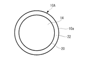
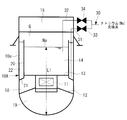
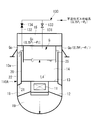
- FIG. 1B is a longitudinal sectional view showing a coolant level at a normal stop in which the coolant is kept warm before starting the reactor in the reactor vessel structure of FIG. 1A.
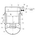
- FIG. 1B is a longitudinal sectional view showing a liquid level when supplying coolant to a coolant retention tank in the reactor vessel structure of FIG. 1A.
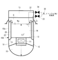
- FIG. 1B is a longitudinal sectional view showing a liquid level at the time of coolant recovery for recovering the same amount of coolant as the filling amount in the reactor vessel structure of FIG. 1A.
- FIG. 1B is a longitudinal cross-sectional view showing a liquid level when supply and recovery of a coolant are completed and a start-up preparation is completed in the reactor vessel structure of FIG. 1A.
- FIG. 1B is a longitudinal sectional view showing a liquid level at the time of start-up of a reactor that has caused a temperature rise in the reactor vessel structure of FIG.
- FIG. 1B is a longitudinal sectional view showing a liquid level during steady state operation of the reactor in which the coolant level is stable in the reactor vessel structure of FIG. 1A.
- FIG. 1B is a longitudinal sectional view showing a liquid level when the reactor is stopped in the reactor vessel structure of FIG. 1A.
- FIG. It is a figure which shows one Embodiment of another reactor vessel structure which concerns on this invention, and is a longitudinal cross-sectional view which shows the outline
- FIG. 9B is a longitudinal sectional view showing a coolant level at a normal stop in which the coolant is kept warm before starting the reactor in the reactor vessel structure of FIG. 9A.
- FIG. 9B is a longitudinal sectional view showing the liquid level at the start of filling of the coolant into the coolant retention tank in the reactor vessel structure of FIG. 9A.
- FIG. 9B is a longitudinal sectional view showing a liquid level at the completion of filling of the coolant into the coolant retention tank in the reactor vessel structure of FIG. 9A.
- FIG. 9B is a longitudinal sectional view showing a liquid level when the filling of the coolant into the coolant retention tank is completed and the reactor is in a state of completion of startup preparation in the reactor vessel structure of FIG. 9A.
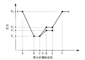
- it is explanatory drawing of the inert gas pressure operation which showed the inert gas pressure corresponding to the reactor operation state of a horizontal axis on the vertical axis
- the reactor vessel 10A of the embodiment shown in FIGS. 1A and 1B is called a hot vessel applied to a fast reactor such as a fast breeder reactor, and houses the core 11 in the internal space of the reactor wall 10a.
- the core 11 is supported by an installation portion such as a skirt portion 12 in the reactor vessel 10A.
- a partition wall 13 is provided on the upper end side of the core 11 to form an upper plenum 14 and an intermediate plenum 18.
- a lower plenum 19 partitioned by the skirt portion 12 is formed below the intermediate plenum 18.
- the upper plenum 14 is a space in which a coolant such as liquid sodium Na, which is a liquid metal, is filled, and an inert gas filling space G such as argon is formed above the liquid surface of the liquid sodium Na. It becomes the space region of the liquid surface structure provided in 10A.
- liquid sodium Na flows into the lower plenum 19 of the reactor vessel 10 from a cold leg pipe (not shown) and is heated in the process of passing through the core 11 from the bottom to the top, as in the conventional structure described above.
- the upper plenum 14 is returned to the cooling system through hot leg piping.
- An inner cylinder 20 installed inside the reactor wall 10a is provided inside the reactor vessel 10A.
- the inner cylinder 20 has an inner cylinder bottom surface 21 formed by coupling the lower end side to the furnace wall 10a.
- the inner cylinder 20 of the bottomed inner cylinder having the inner cylinder bottom surface 21 having a smaller diameter than the reactor wall 10a is installed inside the reactor vessel 10A, the inside of the reactor wall 10a and the outer cylinder 20
- a coolant retention tank 22 that is a space for retaining liquid sodium Na, which is a coolant, is formed between the wall surfaces.
- the inner cylinder 20 is provided up to a position higher than the coolant liquid level L3 during the steady operation of the reactor in the upper plenum 14 of the liquid surface space described above.
- the lower end portion of the inner cylinder 20 and the inner cylinder bottom surface 21 are not desirably adjacent to the upper plenum 14 where thermal transients during severe reactor trips are severe, and therefore are provided on the intermediate plenum 18 side slightly below the partition wall 13. Yes.
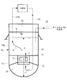
- liquid sodium Na as a coolant is supplied to the coolant retention tank 22, and liquid sodium Na is stored as a coolant supply / recovery system for recovering the liquid sodium Na from the upper plenum 14.
- a sodium filling system 30 connected to a supply source such as a tank is provided.
- This sodium filling system 30 branches into a filling flow path 31 for supplying and filling liquid sodium Na to the coolant retention tank 22 and a recovery flow path 32 for sucking and collecting liquid sodium Na from the upper plenum 14. ing.
- the branching flow path 31 and the recovery flow path 32 after branching are provided with gate valves 33 and 34 that are opened during filling and recovery, respectively.
- the lower end of the filling channel 31 reaches the vicinity of the inner cylinder bottom surface 21, and the liquid sodium Na in the coolant retention tank 22 can be recovered as necessary.
- the filling flow path 31 is a flow path for supplying and filling liquid sodium Na to the coolant retention tank 22, and is used for adjusting the liquid level of the coolant retention tank 22 at the time of starting the nuclear reactor. .
- the recovery flow path 32 is used for recovering the same amount of liquid sodium Na that is supplied to the coolant retention tank 22 from the liquid sodium Na filled in the upper plenum 14 when the reactor is started up. Is done.
- only the gate valve 34 is opened, and the liquid sodium Na in the upper plenum 14 is sucked in the same amount as the amount supplied from the filling flow path 31 and collected in a storage tank or the like of liquid sodium Na.
- FIG. 2 shows the coolant level before reactor activation.
- the liquid sodium Na is filled in a predetermined amount in the coolant boundary and heated to about 200 ° C. to prevent freezing.
- the liquid level in the upper plenum 14 (height from the bottom surface of the reactor vessel 10A to the liquid level) is L1
- the liquid level in the coolant retention tank 22 is slightly higher than the liquid level in the upper plenum 14. Yes.
- FIG. 3 shows the liquid level when liquid sodium is supplied to supply the liquid sodium Na to the coolant retention tank 22 before the reactor is started.
- the gate valve 33 is opened, liquid sodium Na is flowed in the direction of the arrow, and supply of the liquid sodium Na to the coolant retention tank 22 is started.
- the liquid level of the liquid sodium Na in the coolant retention tank 22 rises by the filling amount.
- the liquid sodium filling amount in this case is set until the liquid level in the coolant retention tank 22 coincides with the upper end of the inner cylinder 20.
- FIG. 4 shows the liquid level at the time of coolant recovery for recovering the same amount of liquid sodium Na from the upper plenum 14 before starting the reactor.
- the gate valve 34 is opened and liquid sodium Na is flowed in the direction of the arrow, and the liquid level in the coolant retention tank 22 is the inner cylinder.
- An amount equal to the amount of liquid sodium supplied until it coincides with the upper end of 20 is sucked from the upper plenum 14 and recovered.
- the liquid level in the upper plenum 14 decreases from L1 to L1 ⁇ through the liquid level L2 shown in FIG.
- the filling amount of the liquid sodium Na filling the coolant boundary does not vary from the initial predetermined amount.
- FIG. 5 shows the liquid level before starting the reactor after the coolant supply / recovery is completed.
- the gate valves 33 and 34 are closed, there is no filling and recovery of liquid sodium Na, and the preparation for starting the nuclear reactor is completed.
- FIG. 6 shows the liquid level when the nuclear reactor startup operation is started from the liquid level state of FIG. 5 (at the time of the nuclear reactor startup).
- the liquid sodium Na on the coolant boundary expands as the temperature rises.
- the liquid level L2 in the upper plenum 14 rises to L2 +, and the liquid sodium Na in the coolant retention tank 22 overflows and flows down into the upper plenum 14.
- FIG. 7 shows the liquid level when the reactor is in steady operation (at the time of steady operation of the reactor).
- the liquid sodium Na in the upper plenum 14 is at the liquid level L 3
- the liquid sodium Na in the coolant retention tank 22 is in a state where the liquid level coincides with the upper end of the inner cylinder 20.
- FIG. 8 shows the liquid level when the reactor is shut down.
- the liquid sodium Na shrinks due to temperature drop
- the operation method when starting up the reactor supplies the liquid sodium Na as the coolant to the upper end of the coolant retention tank 22, and in the upper plenum 14.
- recovers the same amount as the supply amount to the coolant retention tank 22 from the filled liquid sodium Na can be implemented. That is, in the liquid level (liquid level) adjustment of the coolant retention tank 22 by the operation of the sodium filling system 30 described above, it is possible to perform the preparation steps for adjusting the liquid level shown in FIGS.
- the preparation step supplies liquid sodium Na to the upper end of the coolant retention tank 22, and from the liquid sodium Na filled in the upper plenum 14, the coolant retention tank 22. Since the same amount as the amount of liquid sodium supplied to the reactor is recovered, the liquid sodium Na expanded by the temperature rise at the time of starting the reactor overflows from the coolant retention tank 22 into the upper plenum 14 having a low liquid level. As a result, when the reactor is started, the liquid level of the liquid sodium Na in contact with the reactor wall 10a of the reactor vessel 10A is expanded by the temperature change at the time of starting the reactor. Always consistent and kept constant.
- the thermal stress in the vicinity of the liquid surface is reduced not only at the time of startup described above, but also at the time of normal stop or emergency stop. The concern caused by thermal stress can be reduced.
- additional sodium cylinder 20 having inner cylinder bottom surface 21 and sodium for supplying liquid sodium Na as a coolant to coolant retention tank 22 are provided. Only the filling system 30 is modified. That is, it is only necessary to add the cylinder 20 having a simple structure in the reactor vessel 10A. Further, since the modification of the sodium filling system 30 is not significant, it can be easily implemented at a relatively low cost. is there. Note that the present invention is not limited to the above-described embodiment, and may be appropriately changed within a range not departing from the gist thereof, such as the type of coolant and inert gas, the configuration of the coolant filling system, and the filling / recovery procedure. can do.
- the reactor vessel 110A of the embodiment shown in FIGS. 9A and 9B is called a hot vessel applied to a fast reactor such as a fast breeder reactor, and stores the core 11 in the internal space of the reactor wall 10a.
- the core 11 is supported by an installation portion such as a skirt portion 12 in the reactor vessel 10A.
- a partition wall 13 is provided on the upper end side of the core 11 to form an upper plenum 14 and an intermediate plenum 18.
- a lower plenum 19 partitioned by the skirt portion 12 is formed below the intermediate plenum 18.
- the upper plenum 14 is a space in which a coolant such as liquid sodium Na, which is a liquid metal, is filled, and an inert gas filling space G such as argon is formed above the liquid surface of the liquid sodium Na. It becomes the space region of the liquid surface structure provided in 110A.
- the liquid sodium Na flows from the cold leg piping (not shown) into the lower plenum 19 of the reactor vessel 110A and is heated while passing through the core 11 from the bottom to the top.
- the upper plenum 14 is returned to the cooling system through hot leg piping.
- an inner cylinder 20 attached to the inside of the reactor wall 10a is provided in the reactor vessel 110A.
- the inner cylinder 20 has an inner cylinder bottom surface 21 formed by coupling the lower end side to the furnace wall 10a.
- the inner cylinder 20 of the bottomed inner cylinder having the inner cylinder bottom surface 21 having a smaller diameter than the reactor wall 10a is installed inside the reactor vessel 110A, the inner wall of the reactor wall 10a and the inner cylinder 20
- the inner cylinder 20 is provided up to a position higher than the coolant liquid level L3 during the steady operation of the reactor in the upper plenum 14 of the liquid surface space described above.
- the lower end portion of the inner cylinder 20 and the inner cylinder bottom surface 21 are not desirably adjacent to the upper plenum 14 where thermal transients during severe reactor trips are severe, and therefore are provided on the intermediate plenum 18 side slightly below the partition wall 13. Yes.
- the illustrated reactor vessel 110A is an important device that constitutes the coolant boundary, and liquid sodium Na is used as an example of the coolant.
- liquid sodium Na is used as an example of the coolant.
- the liquid sodium Na is heated and kept warm according to the operating conditions.
- the liquid sodium Na is filled with an inert gas such as argon (Ar). It has a liquid surface structure provided with an inert gas filling space G.
- the inner side of the inner cylinder 20 is spaced apart from the inner cylinder 20 so as to form a gap that allows smooth flow of liquid sodium Na.
- a partition member 25 having a small-diameter cylindrical shape is provided. The partition member 25 is provided so that the upper end portion side is fixedly supported on the lower surface of the roof deck 15 and the lower end portion extends below a coolant level L5 (see FIG. 12) when filling is completed, which will be described later. .
- the length of the partition member 25 is the most liquid level change in the coolant level in a series of reactor operation states described later (at steady operation, normal stop, filling start, filling completion, and startup preparation completion). It is set so that the lower end portion always enters the liquid surface of the liquid sodium Na when the filling of the surface is lowered. At this time, the lower end of the partition member 25 does not need to penetrate deeply into the liquid level of the liquid sodium Na, and is filled with the inert gas formed inside the upper plenum 14 even when filling is completed when the liquid level is the lowest. It is only necessary that the space G can be divided into the inner space Gi and the outer space Go.
- Such an inner space Gi and an outer space Go are closed spaces. Therefore, by changing the inert gas filling pressure between the two spaces relatively, a pressure difference generated in the two spaces is used to make the coolant retention tank 22. It is possible to fill the coolant (liquid metal). That is, when the inert gas filling pressure in the inner space Gi and the outer space Go is relatively changed, the liquid level of the liquid sodium Na changes due to the pressure difference generated in both spaces. Thus, the coolant liquid sodium Na can be filled up to the upper end of the coolant retention tank 22.
- the inert gas filling space G branches from the inert gas supply (filling) system 130 for supplying an inert gas such as argon, that is, the inert gas is supplied to the inner space Gi.
- a second gas pipe 132 for supplying an inert gas to the outer space Go is additionally provided so as to branch from the first gas pipe 131.
- the first gas pipe 131 and the second gas pipe 132 are provided with a first on-off valve 133 and a second on-off valve 134, respectively, in order to enable independent supply of inert gas.
- an inert gas pressurizing compressor (not shown) is provided at an appropriate position of the inert gas supply system 130.
- the pressure difference between the inner space Gi and the outer space Go described above is the first gas connected to the inert gas supply system 130 to supply the inert gas to the inner space Gi and including the first on-off valve 133.
- the reactor vessel structure of the present embodiment is different from the reactor vessel 110A provided with the coolant retention tank 22 with respect to the partition member 25, the second gas pipe 132, the first on-off valve 133, and the first By adding the 2 on-off valve 134, the liquid metal of the coolant can be filled up to the upper end of the coolant retention tank 22.
- the liquid level of the liquid sodium Na decreases in all of the inner space Gi, the outer space Go, and the coolant retention tank 22 as the temperature decreases.
- the pressure of the inert gas supply system 130 is reduced from P 0 to P 1 for maintenance work. That is, in the inert gas pressure operation of FIG. 14, the reactor operating state changes from point A to point B.
- both the first on-off valve 133 and the second on-off valve 134 are open, the inside of the inner space Gi and the outer space Go is maintained at P 1 having the same pressure. Further, the coolant level in the internal space Gi decreases to L4.
- liquid sodium Na is replenished up to the upper end of the coolant retention tank 22 whose liquid level has been lowered during normal shutdown. That is, in the inert gas pressure operation shown in FIG. 14, the reactor operation state continues from the point B to the point C for maintenance work and the like while maintaining the pressure P 1 while keeping the liquid sodium Na warm. Coolant filling into the coolant retention tank 22 is started. At this time, the second on-off valve 134 of the second gas pipe 132 is fully closed, and the pressure of the inert gas supply system is increased from P 1 to P 2 .
- the liquid sodium Na in the outer space Go reaches the upper end of the coolant retention tank 22 and further flows into the coolant retention tank 22.
- the pressure of the inert gas filling system 130 it is possible to fill the liquid sodium Na into the coolant retention tank 22 whose liquid level has been lowered, and finally the state when the filling is completed as shown in FIG. Become.
- an inert gas pressurizing compressor provided in the inert gas supply system 130 may be used.
- the point D becomes the inert gas pressure operation of FIG. 14, the pressure of the inert gas supply system 130 is maintained at P 2. Therefore, the internal pressure of the inner space Gi is P 2, and the internal pressure in the external space Go to the second on-off valve 134 fully closed are isolated from the inert gas supply system 130, the internal pressure P 2 from the internal space Gi side by receiving the impact increases from P 1 to P 1 '. That is, in the inert gas pressure operation diagram of FIG. 14, when the pressure change is different from the internal space Gi, the pressure change in the external space Go is indicated by a one-dot chain line in the drawing.
- the operating method of the nuclear reactor provided with the reactor vessel structure of this embodiment sets the inert gas filling pressure of the internal space Gi to a pressure higher than the external space Go, pushes down the liquid level of the internal space Gi and externally
- a startup preparation step of raising the liquid level of the space Go and filling the coolant retention tank 22 with liquid sodium Na is provided.
- the pressure difference generated in the internal space Gi and the external space Go is used, and the liquid sodium Na as a coolant is reliably filled up to the upper end portion of the coolant retention tank 22.
- the furnace can be started.
- FIG. 14 shows a state at the completion of the start-up preparation indicated by a point F.
- the coolant level L6 in the upper plenum 14 excluding the inside of the coolant retention tank 22 is slightly higher than the coolant level L5 at the completion of filling shown in FIG.
- the partition member 25 by providing the partition member 25 with the lower end portion extending to the coolant level at the completion of filling, on the inner side separated from the bottomed inner cylinder 20
- the liquid sodium Na which is the liquid metal serving as the coolant
- the coolant retention tank 22 Filling using a pressure difference generated by relatively changing the inert gas filling pressure in the inner space Gi and the outer space Go becomes possible. For this reason, liquid sodium Na can be filled easily and safely into the coolant retention tank 22 in the reactor vessel 110A as preparation for starting up the reactor.
- the reactor vessel 110A described above includes a liquid level detection unit (not shown) that detects the liquid level in the inner space Gi and the outer space Go. That is, in order to detect the liquid level of the liquid sodium Na changing in the internal space G, for example, a liquid level sensor is installed on the wall surface of the partition member 25 or the inner cylinder 20 to be used for adjusting the pressure of the inert gas supply system 130. That's fine. Specifically, the liquid level of the liquid sodium Na that changes in the internal space G is detected stepwise or continuously, and it is confirmed that the liquid level has changed to the predetermined liquid level corresponding to the above-described reactor operating state. Then, the operation control of the inert gas pressurizing compressor can be reliably performed. That is, since the liquid level in the inner space G can be accurately managed, the coolant staying tank 22 can be reliably filled with the liquid sodium Na as the coolant.
- the coolant retention tank 22 not only at the time of startup described above, but also at the time of normal stop or emergency stop when the volume of liquid sodium Na contracts, the liquid sodium Na level in contact with the furnace wall 10a is reduced.
- the drop width can be reduced, and the concern due to thermal stress such as the thermal stress in the vicinity of the liquid level can be reduced.
- the inner cylinder 20 having the inner cylinder bottom surface 21 and the partition member 25 are additionally provided, and the inert gas for supplying the inert gas to the upper plenum 14 is provided. Only the gas filling system 130 is modified. That is, it is only necessary to add the cylinder 20 and the partition member 25 having a simple structure in the reactor vessel 110A, and the modification of the inert gas filling system 130 is not a large-scale structure with a simple configuration. It can be easily implemented at a low cost.
- the liquid level height of the liquid sodium Na in contact with the reactor wall 10a of the reactor vessel 110A is always the upper end of the coolant retention tank 22 when the reactor is started. It is kept in a constant position that matches. As a result, on the wall surface of the reactor vessel 10A, the thermal stress generated due to the relaxation of the temperature gradient in the axial direction is reduced, so that a remarkable effect of further improving the reliability and operability of the reactor vessel is obtained. It is done.
- this embodiment mentioned above can be implemented by the change of the container structure which adds a partition member to a bottomed inner cylinder, and simple modification of an inert gas supply system, additional equipment is minimized and high Has heat resistance.
- a liquid metal (coolant) pipe such as sodium, which requires measures to prevent contact with air, it is highly effective in improving plant reliability and durability.
- the pressure difference is formed.
- the pressure increase is not limited to the inner space Gi side, and for example, reverse pressure adjustment may be performed so as to reduce the pressure on the outer space Go side.
- the above-described embodiment can also be applied to a case where a coolant is filled in a storage bucket as described in Patent Documents 3 to 5, for example.
- the present invention is not limited to the above-described embodiment, and may be appropriately changed within a range not departing from the gist thereof, such as the type of coolant and inert gas, the configuration of the coolant filling system, and the filling / recovery procedure. can do.
Landscapes
- Physics & Mathematics (AREA)
- Engineering & Computer Science (AREA)
- Plasma & Fusion (AREA)
- General Engineering & Computer Science (AREA)
- High Energy & Nuclear Physics (AREA)
- Structure Of Emergency Protection For Nuclear Reactors (AREA)
Abstract
原子炉の起動時等に発生する原子炉容器壁面の熱応力を緩和できる原子炉容器構造を提供する。炉心(11)を収納した原子炉容器(10A)内に、冷却材の液体ナトリウム(Na)を充填した液面上部に不活性ガス充填空間(G)が形成されている有液面構造の上部プレナム(14)を設けた原子炉容器構造において、上部プレナム(14)の炉壁(10a)の内側に、原子炉定常運転時の冷却材液面(L3)より高い位置まで有底の内筒(20)を設置することにより、炉壁(10a)と内筒(20)との間に形成された冷却材滞留槽(22)と、液体ナトリウム(Na)冷却材滞留槽(22)に供給するとともに、上部プレナム(14)内から液体ナトリウム(Na)を回収するナトリウム充填系(30)と、を備えている。
Description
本発明は、たとえば高速増殖炉(Fast Breeder Reactor:FBR)等の高速炉に適用される原子炉容器構造及び原子炉の運転方法に係り、特に、ホットベッセルに好適な原子炉容器構造及び原子炉の運転方法に関する。
従来、高速増殖炉等の高速炉では、たとえば図16や図17に示されるように、ホットベッセルと呼ばれる原子炉容器構造がある。この原子炉容器10では、冷却材としてナトリウムのような液体金属が用いられており、冷却系に接続されたコールドレグ配管17Cから原子炉容器10の下部プレナム19に流入した液体ナトリウムNaは、図中に矢印Fで示すように、炉心11を下から上に通過する過程で加熱され、定格運転時には高温(約550℃)で使用される。なお、加熱された液体ナトリウムNaは、上部プレナム14からホットレグ配管17Hを通って冷却系に戻される。
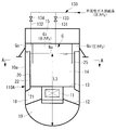
図示の原子炉容器10,110は、冷却材バウンダリを構成する重要機器であり、冷却材の一例として液体ナトリウムNaが使用されている。このような原子炉容器10,110内は、化学的に活発な冷却材であるナトリウムNaが空気と触れることを防ぐため、液体ナトリウムNaの上部に、たとえばアルゴン(Ar)等の不活性ガスを充填した不活性ガス充填空間Gを設けた有液面構造となっている。なお、図中の符号Lは、液体ナトリウムNaの液位を示している。
また、上述した原子炉容器10,110内は、隔壁13によって上下に仕切られ、上部プレナム14及び中間プレナム18を形成している。隔壁13は、炉心11から加熱を受けて上部プレナム14に流入した高温の液体ナトリウムNaが、中間プレナム18へとバイパスすることを防止し、炉心11を支持するスカート部12等の据付部を低温に保つ。
上述した不活性ガスは、上部プレナム14内に充填されている。すなわち、上部プレナム14は、原子炉容器10,110内における有液面空間となる。
なお、ルーフデッキ15は、原子炉容器10,110の蓋であり、不活性ガスバウンダリを形成するとともに、据付部を低温に保つために冷却されている。
図16における符号30は、上部プレナム14内に液体ナトリウムNaを供給して充填するナトリウム充填系である。また、図17における符号130は、不活性ガス充填空間Gにアルゴン等の不活性ガスを供給する不活性ガス供給(充填)系である。
上述した不活性ガスは、上部プレナム14内に充填されている。すなわち、上部プレナム14は、原子炉容器10,110内における有液面空間となる。
なお、ルーフデッキ15は、原子炉容器10,110の蓋であり、不活性ガスバウンダリを形成するとともに、据付部を低温に保つために冷却されている。
図16における符号30は、上部プレナム14内に液体ナトリウムNaを供給して充填するナトリウム充填系である。また、図17における符号130は、不活性ガス充填空間Gにアルゴン等の不活性ガスを供給する不活性ガス供給(充填)系である。
このため、原子炉容器10,110の炉壁10aにおいては、図15の「液位上昇の場合」に示すように、液体ナトリウムNaが存在する冷却材接液部と、不活性ガス充填空間Gとの間において、軸方向に大きな温度勾配を生じ、冷却材の液面近傍部に高い熱応力が発生する。この熱応力は、以下に説明する理由により、特に原子炉の起動時に大きくなる。
原子炉の停止時においては、冷却材として使用する液体ナトリウムNaの凍結を防ぐ目的から、液体ナトリウムNaが約200℃に保温されている。
これに対し、原子炉の起動時には、炉心11からの加熱を受けて液体ナトリウムNaの温度が上昇するので、体積膨張に伴って液体ナトリウムNaの液位もL2からL3に上昇する。なお、この場合の液位L3は、原子炉定常運転時の冷却材液面となる。
これに対し、原子炉の起動時には、炉心11からの加熱を受けて液体ナトリウムNaの温度が上昇するので、体積膨張に伴って液体ナトリウムNaの液位もL2からL3に上昇する。なお、この場合の液位L3は、原子炉定常運転時の冷却材液面となる。
しかし、原子炉容器の材料であるオーステナイト系ステンレス鋼は、その熱伝導性が低いため、液体ナトリウムNaの液面より上の領域、すなわち液体ナトリウムNaと接液していない領域では温度の追従が遅くなる。従って、図15の「液位上昇の場合」に実線で示されるように、原子炉容器10,110の炉壁10aには、液面近傍部(液位L3の液面よりやや上の領域)に大きな温度勾配が生じて高い熱応力を発生する。
原子炉容器の壁面(上述した炉壁10a)に発生する熱応力を緩和する従来技術としては、たとえば特許文献1に開示されているように、原子炉容器の内側に内筒を設置し、容器と内筒の間に炉心入口側の冷却材を流し、冷却材の通過流量を調節して原子炉容器壁の熱応力を緩和するもの(コールドベッセル)がある。
また、特許文献2には、液面熱ラチェット現象の発生を防止するため、原子炉起動時において、原子炉容器内に設置した電磁ポンプを作動させ、冷却材となる液体金属の液位を変化させる高速炉が開示されている。特許文献3~5には、原子炉容器の冷却材液面近傍に、冷却材(液体ナトリウム)を貯留する貯留バケットを設けて熱応力を緩和する方式が開示されており、たとえば貯留バケット内に複数の熱抵抗体を収容する構造や、貯留バケットの断面積が上部及び下部で異なる構造もある。
また、特許文献2には、液面熱ラチェット現象の発生を防止するため、原子炉起動時において、原子炉容器内に設置した電磁ポンプを作動させ、冷却材となる液体金属の液位を変化させる高速炉が開示されている。特許文献3~5には、原子炉容器の冷却材液面近傍に、冷却材(液体ナトリウム)を貯留する貯留バケットを設けて熱応力を緩和する方式が開示されており、たとえば貯留バケット内に複数の熱抵抗体を収容する構造や、貯留バケットの断面積が上部及び下部で異なる構造もある。
上述したように、ホットベッセルの原子炉容器構造においては、原子炉の起動時に液体ナトリウムNaの温度が上昇し、これに伴う熱膨張によって液体ナトリウムNaの液位Lも上昇する。このような原子炉容器10,110の炉壁10aでは、図15に示す「液位上昇の場合」、液体ナトリウムNaの液面近傍において軸方向に大きな温度勾配が生じるので、液面近傍部の熱応力は大きなものとなる。
このため、原子炉の供用期間中には、起動・停止を繰り返すことにより、原子炉容器10,110に対して上述した熱応力が繰り返し発生することになる。従って、この熱応力が大きい場合には、起動のたびに原子炉容器10,110の径が縮む変形(液面ラチェット)や、クリープ疲労による破損の発生が懸念される。
さらに、原子炉容器10,110の健全性を確保するためには、起動にかける日数を長くし、炉壁10aが緩やかな温度上昇をするように、ゆっくりと起動する必要がある。しかし、原子炉を発電等の商用運転に使用するような場合には、起動に要する時間を短縮して定格運転時間を可能な限り延長することが望ましい。
このような熱応力に起因する懸念は、起動時のみならず、通常停止時、緊急停止時にも生じるものである。
さらに、原子炉容器10,110の健全性を確保するためには、起動にかける日数を長くし、炉壁10aが緩やかな温度上昇をするように、ゆっくりと起動する必要がある。しかし、原子炉を発電等の商用運転に使用するような場合には、起動に要する時間を短縮して定格運転時間を可能な限り延長することが望ましい。
このような熱応力に起因する懸念は、起動時のみならず、通常停止時、緊急停止時にも生じるものである。
このような背景から、ホットベッセルの原子炉容器構造においては、原子炉容器の信頼性や運用性をより一層向上させるため、原子炉容器の壁面に発生する熱応力を緩和する方策が必要となる。この方策は、追加設備を最小限に抑え、高い耐熱成立性を有することが望ましい。
本発明は、上記の事情に鑑みてなされたものであり、その目的とするところは、原子炉の起動時等に発生する原子炉容器壁面の熱応力を緩和できる原子炉容器構造及び原子炉の運転方法を提供することにある。
本発明は、上記の事情に鑑みてなされたものであり、その目的とするところは、原子炉の起動時等に発生する原子炉容器壁面の熱応力を緩和できる原子炉容器構造及び原子炉の運転方法を提供することにある。
本発明は、上記の課題を解決するため、下記の手段を採用した。
本発明の第一の態様は、炉心を収納した原子炉容器内に、液体金属の冷却材を充填した液面上部に不活性ガス充填空間が形成されている有液面空間を設けた原子炉容器構造において、前記有液面空間の容器壁面内側に原子炉定常運転時の冷却材液面より高い位置まで有底内筒を設置することにより前記容器壁面と前記内筒との間に形成された冷却材滞留槽と、前記冷却材を前記冷却材滞留槽に供給するとともに、前記有液面空間内から前記冷却材を回収する冷却材供給・回収系統と、を備えた原子炉容器構造である。
本発明の第一の態様は、炉心を収納した原子炉容器内に、液体金属の冷却材を充填した液面上部に不活性ガス充填空間が形成されている有液面空間を設けた原子炉容器構造において、前記有液面空間の容器壁面内側に原子炉定常運転時の冷却材液面より高い位置まで有底内筒を設置することにより前記容器壁面と前記内筒との間に形成された冷却材滞留槽と、前記冷却材を前記冷却材滞留槽に供給するとともに、前記有液面空間内から前記冷却材を回収する冷却材供給・回収系統と、を備えた原子炉容器構造である。
上記本発明の第一の態様に係る原子炉容器構造によれば、有液面空間の容器壁面内側に原子炉定常運転時の冷却材液面より高い位置まで有底内筒を設置することにより容器壁面と内筒との間に形成された冷却材滞留槽と、冷却材を冷却材滞留槽に供給するとともに、有液面空間内から冷却材を回収する冷却材供給・回収系統と、を備えているので、原子炉の起動前に冷却材滞留槽の上端まで冷却材を充填しておくと、起動時の温度上昇により膨張した冷却材が冷却材滞留槽から液面の低い有液面空間内に溢流する。従って、原子炉の起動時には、原子炉容器の壁面と接する冷却材の液面高さを冷却材滞留槽の上端と一致させて、一定に保つことができる。
また、たとえば原子炉の起動時には、冷却材滞留槽に充填された冷却材と同量が有液面空間内から回収できるので、冷却材バウンダリ内の冷却材量は所定の充填量に維持できる。
また、たとえば原子炉の起動時には、冷却材滞留槽に充填された冷却材と同量が有液面空間内から回収できるので、冷却材バウンダリ内の冷却材量は所定の充填量に維持できる。
本発明の第二の態様は、上述の原子炉容器構造を備えている原子炉の運転方法であって、前記冷却材滞留槽の上端まで前記冷却材を供給するとともに、前記有液面空間内に充填されている前記冷却材から前記冷却材滞留槽への供給量と同量を回収する準備工程を備えた原子炉の運転方法である。
上記本発明の第二の態様に係る原子炉の運転方法によれば、冷却材滞留槽の上端まで冷却材を供給するとともに、有液面空間内に充填されている冷却材から冷却材滞留槽への供給量と同量を回収する準備工程を備えているので、原子炉起動時の温度上昇により膨張した冷却材は冷却材滞留槽から液面の低い有液面空間内に溢流する。このため、原子炉の起動時には、原子炉容器の壁面と接する冷却材の液面高さを冷却材滞留槽の上端と一致させ、一定に保つことができる。
また、たとえば原子炉の起動時には、冷却材滞留槽に充填された冷却材と同量が有液面空間内から回収できるので、冷却材バウンダリ内の冷却材量は所定の充填量に維持できる。
また、たとえば原子炉の起動時には、冷却材滞留槽に充填された冷却材と同量が有液面空間内から回収できるので、冷却材バウンダリ内の冷却材量は所定の充填量に維持できる。
本発明の第三の態様は、炉心を収納した原子炉容器内に、液体金属の冷却材を充填した液面上部に不活性ガス充填空間が形成されている有液面空間を設け、該有液面空間の容器壁面内側に、原子炉定常運転時の冷却材液面より高い位置まで有底内筒を設置して前記容器壁面と前記有底内筒との間に形成された冷却材滞留槽を備えている原子炉容器構造であって、前記有底内筒から離間した内側に下端部を充填完了時の液面内まで延在させた仕切部材を設けて前記有液面空間の内部を内側空間及び外側空間に分割し、前記液体金属が、前記内側空間及び前記外側空間の不活性ガス充填圧力を相対的に変化させて生じる圧力差を利用して前記冷却材滞留槽に充填されることを特徴とする原子炉容器構造である。
上記本発明の第三の態様に係る原子炉容器構造によれば、有底内筒から離間した内側に下端部を充填完了時の液面内まで延在させた仕切部材を設けることにより、有液面空間の内部を内側空間及び外側空間に分割し、液体金属が、内側空間及び外側空間の不活性ガス充填圧力を相対的に変化させて生じる圧力差を利用して冷却材滞留槽に充填されるので、原子炉容器内の冷却材滞留槽に液体金属を充填するため、液体金属が空気と接触しないよう十分な配慮が必要となる専用の液体金属供給配管を新たに増設する必要はない。
そして、内部空間の不活性ガス充填圧力を外部空間より高い圧力に設定し、この圧力差により内部空間の液面を押し下げるとともに外部空間の液面を上昇させて冷却材滞留槽へ液体金属を充填するので、冷却材滞留槽の上端部まで確実に液体金属を充填することができ、原子炉の起動時においては、温度上昇により膨張した液体ナトリウムNaが冷却材滞留槽から液面の低い上部プレナム内に溢流することによって、原子炉容器の壁面と接する冷却材の液面高さが冷却材滞留槽の上端と一致する一定位置に保たれる。
上記本発明の第三の態様に係る原子炉容器構造において、前記圧力差は、不活性ガス供給系に接続されて前記内側空間に不活性ガスを供給するとともに第1開閉弁を備えた第1ガス配管と、前記第1開閉弁より上流側で前記第1ガス配管から分岐して前記外側空間に不活性ガスを供給するとともに第2開閉弁を備えた第2ガス配管とを設け、前記第1開閉弁及び前記第2開閉弁の開閉操作により生じさせる構成とされることが好ましい。この構成によれば、仕切部材の追設及び不活性ガス供給系の変更を行う比較的簡単な構造により、起動準備等において原子炉容器内の冷却材滞留槽に液体金属を容易に充填することができる。
上記本発明の第三の態様に係る原子炉容器構造において、前記内側空間内及び外側空間内の液位を検出する液位検出部を備えた構成とされることが好ましい。この構成によれば、内側空間内及び外側空間内の液面管理が可能になるので、冷却材滞留槽に液体金属を確実に充填することができる。
本発明の第四の態様は、上記第三の態様に係る原子炉容器構造を備えている原子炉の運転方法であって、前記内部空間の不活性ガス充填圧力を前記外部空間より高い圧力に設定し、前記内部空間の液面を押し下げるとともに前記外部空間の液面を上昇させて前記冷却材滞留槽へ前記液体金属を充填する起動準備工程を備えた原子炉の運転方法である。
上記本発明の第四の態様に係る原子炉の運転方法によれば、内部空間の不活性ガス充填圧力を外部空間より高い圧力に設定し、内部空間の液面を押し下げるとともに外部空間の液面を上昇させて冷却材滞留槽へ液体金属を充填する起動準備工程を備えているので、両空間に生じる圧力差を利用して冷却材滞留槽の上端部まで液体金属を確実に充填した状態での運転開始が可能になる。このため、原子炉の起動時においては、温度上昇により膨張した液体ナトリウムNaが冷却材滞留槽から液面の低い上部プレナム内に溢流することによって、原子炉容器の壁面と接する冷却材の液面高さが冷却材滞留槽の上端と一致する一定位置に保たれる。
本発明によれば、原子炉の起動時において、原子炉容器の壁面と接する冷却材の液面高さが冷却材滞留槽の上端と一致する一定位置に保たれる。この結果、原子炉容器の壁面においては、軸方向の温度勾配が緩和されて発生する熱応力も小さくなるので、原子炉容器の信頼性や運用性がより一層向上するという顕著な効果を得られる。
本発明は、内筒及び冷却系の改造により実施できるため、追加設備を最小限に抑え、しかも、高い耐熱成立性を有している。
本発明は、内筒及び冷却系の改造により実施できるため、追加設備を最小限に抑え、しかも、高い耐熱成立性を有している。
また、本発明によれば、原子炉の起動時において、温度上昇により膨張した液体ナトリウムNaが冷却材滞留槽から液面の低い上部プレナム内に溢流することによって、原子炉容器の壁面と接する冷却材の液面高さが冷却材滞留槽の上端と一致する一定位置に保たれる。この結果、原子炉容器の壁面においては、軸方向の温度勾配が緩和されて発生する熱応力も小さくなるので、原子炉容器の信頼性や運用性がより一層向上するという顕著な効果を得られる。
本発明は、有底内筒と仕切部材を追加する容器構造の変更と、不活性ガス供給系の簡単な改造により実施できるため、追加設備を最小限に抑え、しかも、高い耐熱成立性を有している。特に、空気との接触防止対策が必要となるナトリウムのような液体金属(冷却材)配管を増設する必要がないため、プラントの信頼性や耐久性の向上に大きな効果を奏する。
本発明は、有底内筒と仕切部材を追加する容器構造の変更と、不活性ガス供給系の簡単な改造により実施できるため、追加設備を最小限に抑え、しかも、高い耐熱成立性を有している。特に、空気との接触防止対策が必要となるナトリウムのような液体金属(冷却材)配管を増設する必要がないため、プラントの信頼性や耐久性の向上に大きな効果を奏する。
〔第一の実施形態〕
以下、本発明に係る原子炉容器構造及び原子炉の運転方法の第一の実施形態を図面に基づいて説明する。
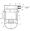
図1A及び図1Bに示す実施形態の原子炉容器10Aは、高速増殖炉等の高速炉に適用されるホットベッセルと呼ばれるものであり、炉壁10aの内部空間に炉心11を収納している。この炉心11は、原子炉容器10A内でスカート部12等の据付部により支持されている。
以下、本発明に係る原子炉容器構造及び原子炉の運転方法の第一の実施形態を図面に基づいて説明する。
図1A及び図1Bに示す実施形態の原子炉容器10Aは、高速増殖炉等の高速炉に適用されるホットベッセルと呼ばれるものであり、炉壁10aの内部空間に炉心11を収納している。この炉心11は、原子炉容器10A内でスカート部12等の据付部により支持されている。
原子炉容器10Aの内部は、炉心11の上端部側に隔壁13を設けて上部プレナム14及び中間プレナム18を形成している。なお、中間プレナム18の下方には、スカート部12によって仕切られた下部プレナム19が形成されている。
上部プレナム14は、液体金属である液体ナトリウムNa等の冷却材が充填されるとともに、液体ナトリウムNaの液面上部にアルゴン等の不活性ガス充填空間Gが形成される空間であり、原子炉容器10A内に設けた有液面構造の空間領域となる。なお、液体ナトリウムNaは、上述した従来構造と同様に、図示を省略したコールドレグ配管から原子炉容器10の下部プレナム19に流入し、炉心11を下から上に通過する過程で加熱された後に、上部プレナム14からホットレグ配管を通って冷却系に戻される。
上部プレナム14は、液体金属である液体ナトリウムNa等の冷却材が充填されるとともに、液体ナトリウムNaの液面上部にアルゴン等の不活性ガス充填空間Gが形成される空間であり、原子炉容器10A内に設けた有液面構造の空間領域となる。なお、液体ナトリウムNaは、上述した従来構造と同様に、図示を省略したコールドレグ配管から原子炉容器10の下部プレナム19に流入し、炉心11を下から上に通過する過程で加熱された後に、上部プレナム14からホットレグ配管を通って冷却系に戻される。
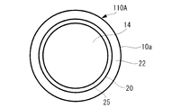
原子炉容器10Aの内部には、炉壁10aの内側に設置された内筒20を備えている。この内筒20は、下端部側を炉壁10aに結合して形成された内筒底面21を有している。この結果、原子炉容器10Aの内側には、炉壁10aより小径で内筒底面21を有する有底内筒の内筒20が設置されているので、炉壁10aの内側と内筒20の外壁面との間には、冷却材である液体ナトリウムNaを滞留させるための空間である冷却材滞留槽22が形成されている。
この内筒20は、上述した有液面空間の上部プレナム14内において、原子炉定常運転時の冷却材液位L3よりも高い位置まで設けられている。
なお、内筒20の下端部及び内筒底面21は、原子炉トリップ時の熱過渡が厳しい上部プレナム14に隣接することは望ましくないため、隔壁13よりやや下方の中間プレナム18側に設けられている。
この内筒20は、上述した有液面空間の上部プレナム14内において、原子炉定常運転時の冷却材液位L3よりも高い位置まで設けられている。
なお、内筒20の下端部及び内筒底面21は、原子炉トリップ時の熱過渡が厳しい上部プレナム14に隣接することは望ましくないため、隔壁13よりやや下方の中間プレナム18側に設けられている。
また、原子炉容器10Aには、冷却材の液体ナトリウムNaを冷却材滞留槽22に供給するとともに、上部プレナム14内から液体ナトリウムNaを回収する冷却材供給・回収系統として、液体ナトリウムNaの貯蔵タンク等の供給源に接続されたナトリウム充填系30が設けられている。
このナトリウム充填系30は、冷却材滞留槽22に液体ナトリウムNaを供給して充填する充填流路31と、上部プレナム14内から液体ナトリウムNaを吸入して回収する回収流路32とに分岐している。なお、分岐後の充填流路31及び回収流路32には、それぞれ充填時及び回収時に開操作する仕切弁33,34が設置されている。また、充填流路31の下端は内筒底面21近傍まで達し、必要に応じて冷却材滞留槽22の液体ナトリウムNaを回収できる。
このナトリウム充填系30は、冷却材滞留槽22に液体ナトリウムNaを供給して充填する充填流路31と、上部プレナム14内から液体ナトリウムNaを吸入して回収する回収流路32とに分岐している。なお、分岐後の充填流路31及び回収流路32には、それぞれ充填時及び回収時に開操作する仕切弁33,34が設置されている。また、充填流路31の下端は内筒底面21近傍まで達し、必要に応じて冷却材滞留槽22の液体ナトリウムNaを回収できる。
充填流路31は、冷却材滞留槽22に液体ナトリウムNaを供給して充填する流路であり、原子炉の起動時等において、冷却材滞留槽22の液面を調整するために使用される。このとき、仕切弁33のみが開とされ、液体ナトリウムNaは冷却材滞留槽22の上端まで充填される。
回収流路32は、原子炉の起動時等において、上部プレナム14内に充填されている液体ナトリウムNaから、冷却材滞留槽22へ供給した量と同量の液体ナトリウムNaを回収するために使用される。このとき、仕切弁34のみが開とされ、上部プレナム14内の液体ナトリウムNaが充填流路31から供給した量と同量吸引され、液体ナトリウムNaの貯蔵タンク等に回収される。
回収流路32は、原子炉の起動時等において、上部プレナム14内に充填されている液体ナトリウムNaから、冷却材滞留槽22へ供給した量と同量の液体ナトリウムNaを回収するために使用される。このとき、仕切弁34のみが開とされ、上部プレナム14内の液体ナトリウムNaが充填流路31から供給した量と同量吸引され、液体ナトリウムNaの貯蔵タンク等に回収される。
このような原子炉容器構造によれば、原子炉の起動前に冷却材滞留槽22の上端まで液体ナトリウムNaを充填しておくと、起動時の温度上昇により膨張した液体ナトリウムNaが冷却材滞留槽22から液面の低い上部プレナム14内に溢流する。従って、原子炉の起動時には、原子炉容器10Aの壁面と接する液体ナトリウムNaの液面高さが冷却材滞留槽22の上端と一致し、定常運転まで変動することなく一定に保たれる。
以下、原子炉の起動から停止まで、ナトリウム充填系30の操作による冷却材滞留槽22の液位(液面)調整について説明する。
図2は、原子炉起動前の冷却材液位を示している。この場合、液体ナトリウムNaは、冷却材バウンダリには所定量充填されており、凍結防止のために200℃程度まで加熱されている。このとき、上部プレナム14内の液位(原子炉容器10Aの底面から液面までの高さ)はL1であり、冷却材滞留槽22の液面は上部プレナム14の液位よりやや高くなっている。
図2は、原子炉起動前の冷却材液位を示している。この場合、液体ナトリウムNaは、冷却材バウンダリには所定量充填されており、凍結防止のために200℃程度まで加熱されている。このとき、上部プレナム14内の液位(原子炉容器10Aの底面から液面までの高さ)はL1であり、冷却材滞留槽22の液面は上部プレナム14の液位よりやや高くなっている。
図3は、原子炉起動前において、冷却材滞留槽22に液体ナトリウムNaを供給する液体ナトリウム供給時の液位を示している。この場合、図2に示した原子炉起動前の冷却材液位から、仕切弁33を開として矢印方向に液体ナトリウムNaを流し、冷却材滞留槽22に対する液体ナトリウムNaの供給を開始する。この結果、冷却材滞留槽22内の液体ナトリウムNaは、充填量分だけ液面が上昇する。この場合の液体ナトリウム充填量は、冷却材滞留槽22内の液面が内筒20の上端と一致するまでとする。
図4は、原子炉起動前において、上部プレナム14内から充填量と同量の液体ナトリウムNaを回収する冷却材回収時の液位が示されている。この場合、図2及び図3に示した原子炉起動前の冷却材液位状態から、仕切弁34を開として矢印方向に液体ナトリウムNaを流し、冷却材滞留槽22内の液面が内筒20の上端と一致するまで供給した液体ナトリウム充填量と同量を上部プレナム14から吸引して回収する。
この結果、上部プレナム14内の液位はL1からL1-を経て、図5に示す液位L2に低下する。この操作により、冷却材バウンダリに充填されている液体ナトリウムNaの充填量は、当初の所定量から変動することはない。
この結果、上部プレナム14内の液位はL1からL1-を経て、図5に示す液位L2に低下する。この操作により、冷却材バウンダリに充填されている液体ナトリウムNaの充填量は、当初の所定量から変動することはない。
図5は、冷却材供給・回収が完了した原子炉起動前の液位を示している。この状態では、仕切弁33,34が閉じられ、液体ナトリウムNaの充填及び回収はなく、原子炉を起動する準備が完了した状態となる。
図6は、図5の液位状態から原子炉の起動操作を開始した場合(原子炉起動時)の液位を示している。この場合、原子炉の起動により液体ナトリウムNaが温度上昇するので、冷却材バウンダリの液体ナトリウムNaが温度上昇に伴って膨張する。この結果、上部プレナム14内の液位L2からL2+に上昇するとともに、冷却材滞留槽22の液体ナトリウムNaが溢流して上部プレナム14内に流下する。
図6は、図5の液位状態から原子炉の起動操作を開始した場合(原子炉起動時)の液位を示している。この場合、原子炉の起動により液体ナトリウムNaが温度上昇するので、冷却材バウンダリの液体ナトリウムNaが温度上昇に伴って膨張する。この結果、上部プレナム14内の液位L2からL2+に上昇するとともに、冷却材滞留槽22の液体ナトリウムNaが溢流して上部プレナム14内に流下する。
図7は、原子炉が定常運転されている場合(原子炉定常運転時)の液位を示している。この場合、上部プレナム14内の液体ナトリウムNaは液位L3となり、冷却材滞留槽22の液体ナトリウムNaは液面が内筒20の上端と一致した状態にある。
図8は、原子炉を停止した場合の液位が示されている。この場合、液体ナトリウムNaは温度降下に伴い収縮するので、上部プレナム14内の液位は定常運転時の液位L3から降下し液位L3-を経て、最終的には凍結防止の加熱温度まで低下し、図2に示す原子炉起動前の冷却材液位L1となる。
図8は、原子炉を停止した場合の液位が示されている。この場合、液体ナトリウムNaは温度降下に伴い収縮するので、上部プレナム14内の液位は定常運転時の液位L3から降下し液位L3-を経て、最終的には凍結防止の加熱温度まで低下し、図2に示す原子炉起動前の冷却材液位L1となる。
このように、上述した実施形態の原子炉容器10Aでは、原子炉を起動する際の運転方法が、冷却材滞留槽22の上端まで冷却材の液体ナトリウムNaを供給するとともに、上部プレナム14内に充填されている液体ナトリウムNaから冷却材滞留槽22への供給量と同量を回収する準備工程を実施できる。すなわち、上述したナトリウム充填系30の操作による冷却材滞留槽22の液位(液面)調整において、図2から図4に示した液位調整を行う準備工程が実施可能となる。
このような原子炉の運転方法において、準備工程は、冷却材滞留槽22の上端まで液体ナトリウムNaを供給し、かつ、上部プレナム14内に充填されている液体ナトリウムNaから、冷却材滞留槽22に供給した液体ナトリウム量と同量を回収するので、原子炉起動時の温度上昇により膨張した液体ナトリウムNaは、冷却材滞留槽22から液面の低い上部プレナム14内に溢流する。
この結果、原子炉起動時において、原子炉容器10Aの炉壁10aと接する液体ナトリウムNaの液面高さは、原子炉起動時の温度変化により膨張しても、冷却材滞留槽22の上端と常に一致して一定に保たれる。
この結果、原子炉起動時において、原子炉容器10Aの炉壁10aと接する液体ナトリウムNaの液面高さは、原子炉起動時の温度変化により膨張しても、冷却材滞留槽22の上端と常に一致して一定に保たれる。
このようにして、原子炉起動時に炉壁10aと接する液体ナトリウムNaの液位を一定に保つことができると、図15に示す「液位一定の場合」のように、液体ナトリウムNaの液面近傍において軸方向に生じていた大きな温度勾配を低減でき、この結果、液面近傍部の熱応力も小さくなる。
このため、原子炉の供用期間中に起動・停止を繰り返しても、原子炉容器10Aに対して繰り返し発生する熱応力を低減できるので、起動のたびに原子炉容器10Aの径が縮む変形(液面ラチェット)やクリープ疲労による破損の問題を低減または解消することができる。
また、液体ナトリウムNaの液位を一定に保つ(あるいは小さくする)ことができると、上述した起動時のみならず、通常停止時や緊急停止時においても、液面近傍部の熱応力を小さくするなど、熱応力に起因する懸念を軽減することができる。
このため、原子炉の供用期間中に起動・停止を繰り返しても、原子炉容器10Aに対して繰り返し発生する熱応力を低減できるので、起動のたびに原子炉容器10Aの径が縮む変形(液面ラチェット)やクリープ疲労による破損の問題を低減または解消することができる。
また、液体ナトリウムNaの液位を一定に保つ(あるいは小さくする)ことができると、上述した起動時のみならず、通常停止時や緊急停止時においても、液面近傍部の熱応力を小さくするなど、熱応力に起因する懸念を軽減することができる。
また、上述した実施形態は、図16に示した従来例に対する追加設備として、内筒底面21を有する内筒20の追設と、冷却材滞留槽22へ冷却材の液体ナトリウムNaを供給するナトリウム充填系30の改造のみである。すなわち、原子炉容器10A内は単純な構造の円筒20を追加するだけでよく、しかも、ナトリウム充填系30の改造も大がかりなものではないから、比較的低コストで容易に実施することが可能である。
なお、本発明は上述した実施形態に限定されることはなく、たとえば冷却材や不活性ガスの種類、冷却材充填系の構成や充填・回収手順など、その要旨を逸脱しない範囲内において適宜変更することができる。
なお、本発明は上述した実施形態に限定されることはなく、たとえば冷却材や不活性ガスの種類、冷却材充填系の構成や充填・回収手順など、その要旨を逸脱しない範囲内において適宜変更することができる。
〔第二の実施形態〕
以下、本発明に係る原子炉容器構造及び原子炉の運転方法の第二の実施形態を図面に基づいて説明する。なお、上述した実施形態と同様の部分には同じ符号を付している。
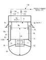
図9A及び図9Bに示す実施形態の原子炉容器110Aは、高速増殖炉等の高速炉に適用されるホットベッセルと呼ばれるものであり、炉壁10aの内部空間に炉心11を収納している。この炉心11は、原子炉容器10A内でスカート部12等の据付部により支持されている。
以下、本発明に係る原子炉容器構造及び原子炉の運転方法の第二の実施形態を図面に基づいて説明する。なお、上述した実施形態と同様の部分には同じ符号を付している。
図9A及び図9Bに示す実施形態の原子炉容器110Aは、高速増殖炉等の高速炉に適用されるホットベッセルと呼ばれるものであり、炉壁10aの内部空間に炉心11を収納している。この炉心11は、原子炉容器10A内でスカート部12等の据付部により支持されている。
原子炉容器110Aの内部は、炉心11の上端部側に隔壁13を設けて上部プレナム14及び中間プレナム18を形成している。なお、中間プレナム18の下方には、スカート部12によって仕切られた下部プレナム19が形成されている。
上部プレナム14は、液体金属である液体ナトリウムNa等の冷却材が充填されるとともに、液体ナトリウムNaの液面上部にアルゴン等の不活性ガス充填空間Gが形成される空間であり、原子炉容器110A内に設けた有液面構造の空間領域となる。なお、液体ナトリウムNaは、上述した従来構造と同様に、図示を省略したコールドレグ配管から原子炉容器110Aの下部プレナム19に流入し、炉心11を下から上に通過する過程で加熱された後に、上部プレナム14からホットレグ配管を通って冷却系に戻される。
上部プレナム14は、液体金属である液体ナトリウムNa等の冷却材が充填されるとともに、液体ナトリウムNaの液面上部にアルゴン等の不活性ガス充填空間Gが形成される空間であり、原子炉容器110A内に設けた有液面構造の空間領域となる。なお、液体ナトリウムNaは、上述した従来構造と同様に、図示を省略したコールドレグ配管から原子炉容器110Aの下部プレナム19に流入し、炉心11を下から上に通過する過程で加熱された後に、上部プレナム14からホットレグ配管を通って冷却系に戻される。
原子炉容器110Aの内部には、炉壁10aの内側に取り付けられた内筒20を備えている。この内筒20は、下端部側を炉壁10aに結合して形成された内筒底面21を有している。このように、原子炉容器110Aの内側には、炉壁10aより小径で内筒底面21を有する有底内筒の内筒20が設置されているので、炉壁10aの内側と内筒20の外壁面との間には、冷却材である液体ナトリウムNaを滞留させるための空間である冷却材滞留槽22が形成されている。
この内筒20は、上述した有液面空間の上部プレナム14内において、原子炉定常運転時の冷却材液位L3よりも高い位置まで設けられている。
なお、内筒20の下端部及び内筒底面21は、原子炉トリップ時の熱過渡が厳しい上部プレナム14に隣接することは望ましくないため、隔壁13よりやや下方の中間プレナム18側に設けられている。
なお、内筒20の下端部及び内筒底面21は、原子炉トリップ時の熱過渡が厳しい上部プレナム14に隣接することは望ましくないため、隔壁13よりやや下方の中間プレナム18側に設けられている。
そして、図示の原子炉容器110Aは、冷却材バウンダリを構成する重要機器であり、冷却材の一例として液体ナトリウムNaが使用されている。この場合、液体ナトリウムNaは、凍結防止のため200℃程度以下の低温とならないようにする必要があり、従って、運転状況に応じて加熱及び保温がなされている。また、原子炉容器110Aの内部は、化学的に活性な冷却材であるナトリウムNaが空気と触れることを防ぐため、液体ナトリウムNaの上部に、たとえばアルゴン(Ar)等の不活性ガスを充填した不活性ガス充填空間Gを設けた有液面構造となっている。
このような原子炉容器110Aの内部に対し、本実施形態では、内筒20から液体ナトリウムNaのスムーズな流通を可能にする程度の隙間を形成するように離間した内側に、内筒20よりも小径の円筒形状を有する仕切部材25が設けられている。この仕切部材25は、上端部側がルーフデッキ15の下面に固定支持され、下端部が後述する充填完了時の冷却材液位L5(図12参照)より下方まで延在するように設けられている。
このような原子炉容器110Aの内部に対し、本実施形態では、内筒20から液体ナトリウムNaのスムーズな流通を可能にする程度の隙間を形成するように離間した内側に、内筒20よりも小径の円筒形状を有する仕切部材25が設けられている。この仕切部材25は、上端部側がルーフデッキ15の下面に固定支持され、下端部が後述する充填完了時の冷却材液位L5(図12参照)より下方まで延在するように設けられている。
すなわち、仕切部材25の長さは、後述する一連の原子炉運転状態(定常運転時、通常停止時、充填開始時、充填完了時及び起動準備完了時)において、冷却材液位変化で最も液面が低下する充填完了時に、下端部が必ず液体ナトリウムNaの液面内に入り込むように設定されている。このとき、仕切部材25の下端部は、液体ナトリウムNaの液面内に深く入り込む必要はなく、最も液面が低下する充填完了時においても、上部プレナム14の内部に形成された不活性ガス充填空間Gを内側空間Gi及び外側空間Goに分割できればよい。
このような内側空間Gi及び外側空間Goは閉空間であり、従って、両空間の不活性ガス充填圧力を相対的に変化させることにより、両空間に生じる圧力差を利用して冷却材滞留槽22に冷却材(液体金属)の充填が可能になる。すなわち、内側空間Gi及び外側空間Go内の不活性ガス充填圧力を相対的に変化させると、両空間内に生じる圧力差により液体ナトリウムNaの液位が変化するので、この液位変化を利用して冷却材滞留槽22の上端部まで冷却材の液体ナトリウムNaを充填することができる。
また、本実施形態では、不活性ガス充填空間Gにアルゴン等の不活性ガスを供給する不活性ガス供給(充填)系130から分岐して、すなわち、内側空間Giに不活性ガスを供給する第1ガス配管131から分岐するようにして、外側空間Goに不活性ガスを供給する第2ガス配管132が追設されている。第1ガス配管131及び第2ガス配管132には、それぞれ単独での不活性ガス供給を可能にするため、第1開閉弁133及び第2開閉弁134が設けられている。
なお、不活性ガス供給系130の適所には、図示省略の不活性ガス昇圧用圧縮機が設けられている。
なお、不活性ガス供給系130の適所には、図示省略の不活性ガス昇圧用圧縮機が設けられている。
換言すれば、上述した内側空間Gi及び外側空間Goの圧力差は、不活性ガス供給系130に接続されて内側空間Giに不活性ガスを供給するとともに第1開閉弁133を備えた第1ガス配管131と、第1開閉弁133より上流側で第1ガス配管131から分岐して外側空間Goに不活性ガスを供給するとともに第2開閉弁を備えた第2ガス配管132とを設け、第1開閉弁133及び第2開閉弁134の開閉操作により生じさせることができる。
このように、本実施形態の原子炉容器構造は、冷却材滞留槽22を備えた原子炉容器110Aに対して、仕切部材25と、第2ガス配管132と、第1開閉弁133と、第2開閉弁134とを追加したことにより、冷却材の液体金属を冷却材滞留槽22の上端部まで充填可能となる。
このように、本実施形態の原子炉容器構造は、冷却材滞留槽22を備えた原子炉容器110Aに対して、仕切部材25と、第2ガス配管132と、第1開閉弁133と、第2開閉弁134とを追加したことにより、冷却材の液体金属を冷却材滞留槽22の上端部まで充填可能となる。
以下、冷却材滞留槽22に液体ナトリウムNaを充填する手順について、一連の原子炉運転状態(定常運転時、通常停止時、充填開始時、充填完了時及び起動準備完了時)とともに説明する。
図9Aに示す原子炉の定常運転時には、不活性ガス供給系130から圧力P0に設定された不活性ガスが供給されている。このとき、第1開閉弁133及び第2開閉弁134はいずれも開とされ、従って、内側空間Gi及び外側空間Goの内部は、ともに同圧のP0に維持されている。なお、定常運転時における液体ナトリウムNaの液位はL3であり、冷却材滞留槽22には、上端部まで液体ナトリウムNaが満たされている。
図9Aに示す原子炉の定常運転時には、不活性ガス供給系130から圧力P0に設定された不活性ガスが供給されている。このとき、第1開閉弁133及び第2開閉弁134はいずれも開とされ、従って、内側空間Gi及び外側空間Goの内部は、ともに同圧のP0に維持されている。なお、定常運転時における液体ナトリウムNaの液位はL3であり、冷却材滞留槽22には、上端部まで液体ナトリウムNaが満たされている。
このような定常運転時の状態は、原子炉運転状態と不活性ガス圧力との関係を示す不活性ガス圧力運用の説明図(図14参照)において、点Aまで継続されている。
なお、図9から図13において、第1開閉弁133及び第2開閉弁134は、全閉状態が黒塗りで表示されている。
なお、図9から図13において、第1開閉弁133及び第2開閉弁134は、全閉状態が黒塗りで表示されている。
図10に示す原子炉の通常停止時には、内側空間Gi、外側空間Go及び冷却材滞留槽22の全てにおいて、温度低下に伴って液体ナトリウムNaの液位が低下する。この液位低下とともに、不活性ガス供給系130の圧力は、保守作業のためP0からP1に低減される。すなわち、図14の不活性ガス圧力運用において、原子炉運転状態は点Aから点Bに変化している。
この場合、第1開閉弁133及び第2開閉弁134はいずれも開であるから、内側空間Gi及び外側空間Goの内部は同圧のP1に維持される。また、内部空間Giの冷却材液位はL4まで低下する。
この場合、第1開閉弁133及び第2開閉弁134はいずれも開であるから、内側空間Gi及び外側空間Goの内部は同圧のP1に維持される。また、内部空間Giの冷却材液位はL4まで低下する。
図11に示す原子炉の充填開始時では、通常停止時に液面低下した冷却材滞留槽22の上端部まで液体ナトリウムNaを補充する。すなわち、図14に示す不活性ガス圧力運用において、原子炉運転状態は、保守作業等のため点Bから点Cまで、液体ナトリウムNaを保温しながら圧力P1を維持する状態を継続した後、冷却材滞留槽22に対する冷却材充填を開始する。このとき、第2ガス配管132の第2開閉弁134を全閉とし、かつ、不活性ガス供給系の圧力をP1からP2に上昇させる。
こうして冷却材充填が開始されると、図14の不活性ガス圧力運用において、不活性ガスの圧力は冷却材充填開始前の点C(図10)から冷却材充填中の領域C′(図11)に変化する。
この結果、閉空間である内側空間Giと外側空間Goとの間には圧力差が生じ、高圧側(圧力P2)の内側空間Giでは液面が冷却材液位L4-に低下し、低圧側(圧力P1)の外側空間Goでは液面が上昇する。これは、内側空間Giと外側空間Goとの間が連通しており、液体ナトリウムNaの流通が可能になっているためであり、内側空間Giで液面低下した液体ナトリウムNaの容積分だけ外側空間Goの液面が上昇する。
この結果、閉空間である内側空間Giと外側空間Goとの間には圧力差が生じ、高圧側(圧力P2)の内側空間Giでは液面が冷却材液位L4-に低下し、低圧側(圧力P1)の外側空間Goでは液面が上昇する。これは、内側空間Giと外側空間Goとの間が連通しており、液体ナトリウムNaの流通が可能になっているためであり、内側空間Giで液面低下した液体ナトリウムNaの容積分だけ外側空間Goの液面が上昇する。
このような液面変化により、外側空間Go内の液体ナトリウムNaは、液面が冷却材滞留槽22の上端部に到達し、さらに冷却材滞留槽22の内部に流入する。この結果、不活性ガス充填系130の圧力調整により、液面低下した冷却材滞留槽22の内部に液体ナトリウムNaを充填することができ、最終的には図12に示す充填完了時の状態となる。なお、活性ガス充填系130の圧力調整には、不活性ガス供給系130にもともと設けられている不活性ガス昇圧用圧縮機を利用すればよい。
図12の充填完了時は、図14の不活性ガス圧力運用における点Dとなり、不活性ガス供給系130の圧力がP2に維持されている。
従って、内部空間Giの内部圧力はP2となり、全閉の第2開閉弁134により不活性ガス供給系130と遮断されている外部空間Goの内部圧力は、内部空間Gi側から内部圧力P2の影響を受けることにより、P1からP1′に上昇する。すなわち、図14の不活性ガス圧力運用図においては、圧力変化が内部空間Giと異なる場合について、外部空間Goの圧力変化は図中に一点鎖線で示されている。
従って、内部空間Giの内部圧力はP2となり、全閉の第2開閉弁134により不活性ガス供給系130と遮断されている外部空間Goの内部圧力は、内部空間Gi側から内部圧力P2の影響を受けることにより、P1からP1′に上昇する。すなわち、図14の不活性ガス圧力運用図においては、圧力変化が内部空間Giと異なる場合について、外部空間Goの圧力変化は図中に一点鎖線で示されている。
そして、本実施形態の原子炉容器構造を備えた原子炉の運転方法は、内部空間Giの不活性ガス充填圧力を外部空間Goより高い圧力に設定し、内部空間Giの液面を押し下げるとともに外部空間Goの液面を上昇させて冷却材滞留槽22へ液体ナトリウムNaを充填する起動準備工程を備えている。
このような原子炉の運転方法によれば、内部空間Gi及び外部空間Goに生じる圧力差を利用し、冷却材滞留槽22の上端部まで冷却材の液体ナトリウムNaを確実に充填した状態で原子炉の運転開始が可能になる。この結果、原子炉の起動時においては、温度上昇により膨張した液体ナトリウムNaが冷却材滞留槽22から液面の低い上部プレナム14内に溢流することによって、原子炉容器110Aの炉壁10aと接する冷却材の液面高さが冷却材滞留槽22の上端と一致した一定位置に保たれる。
このような原子炉の運転方法によれば、内部空間Gi及び外部空間Goに生じる圧力差を利用し、冷却材滞留槽22の上端部まで冷却材の液体ナトリウムNaを確実に充填した状態で原子炉の運転開始が可能になる。この結果、原子炉の起動時においては、温度上昇により膨張した液体ナトリウムNaが冷却材滞留槽22から液面の低い上部プレナム14内に溢流することによって、原子炉容器110Aの炉壁10aと接する冷却材の液面高さが冷却材滞留槽22の上端と一致した一定位置に保たれる。
こうして冷却材の充填が完了すると、図14の不活性ガス圧力運用における点Dから点Eまで充填完了時の状態が維持される。この後、上述した充填完了時の状態から第2開閉弁134を全開とすると内側空間Gi及び外側空間Goがともに圧力P2となり、さらに不活性ガス供給系130の圧力をP0に上昇させると、図14に点Fで示す起動準備完了時の状態となる。
このとき、液体ナトリウムNaは保温されているため温度変化はなく、冷却材滞留槽22の内部には上端まで液体ナトリウムNaが充填されている。また、冷却材滞留槽22の内部を除く上部プレナム14内の冷却材液位L6は、図12に示す充填完了時の冷却材液位L5よりやや上昇する。
このとき、液体ナトリウムNaは保温されているため温度変化はなく、冷却材滞留槽22の内部には上端まで液体ナトリウムNaが充填されている。また、冷却材滞留槽22の内部を除く上部プレナム14内の冷却材液位L6は、図12に示す充填完了時の冷却材液位L5よりやや上昇する。
このような本実施形態の原子炉容器構造によれば、有底の内筒20から離間した内側に下端部を充填完了時の冷却材液面内まで延在させた仕切部材25を設けることにより、有液面空間となる不活性ガス充填空間Gの内部を内側空間Gi及び外側空間Goに分割し、冷却材となる液体金属の液体ナトリウムNaを冷却材滞留槽22に充填する際には、内側空間Gi及び外側空間Goの不活性ガス充填圧力を相対的に変化させて生じる圧力差を利用した充填が可能となる。
このため、原子炉の起動準備として、原子炉容器110A内の冷却材滞留槽22に液体ナトリウムNaを容易かつ安全に充填できるようになる。すなわち、液体金属が空気と接触しないよう十分な配慮を必要とする液体ナトリウムNaの液体金属供給配管を新たに増設する必要はなく、仕切部材25の増設と不活性ガス供給系130の簡単な改造とを実施するだけで、特に原子炉の起動時に問題となる炉壁10aの熱応力対策が実現する。
このため、原子炉の起動準備として、原子炉容器110A内の冷却材滞留槽22に液体ナトリウムNaを容易かつ安全に充填できるようになる。すなわち、液体金属が空気と接触しないよう十分な配慮を必要とする液体ナトリウムNaの液体金属供給配管を新たに増設する必要はなく、仕切部材25の増設と不活性ガス供給系130の簡単な改造とを実施するだけで、特に原子炉の起動時に問題となる炉壁10aの熱応力対策が実現する。
この熱応力対策について具体的に説明すると、図13に示す起動準備完了時のように、原子炉の起動前に冷却材滞留槽22の上端まで液体ナトリウムNaを充填しておくと、起動時の温度上昇により膨張した液体ナトリウムNaが冷却材滞留槽22から液面の低い上部プレナム14内に溢流する。従って、原子炉の起動時には、原子炉容器110Aの壁面と接する液体ナトリウムNaの液面高さが冷却材滞留槽22の上端と一致し、定常運転まで変動することなく一定に保たれる。
ところで、上述した原子炉容器110Aは、内側空間Gi内及び外側空間Go内の液位を検出する液位検出部(不図示)を備えていることが望ましい。すなわち、内部空間G内で変化する液体ナトリウムNaの液位を検出するため、たとえば仕切部材25や内筒20の壁面に液面センサを設置して不活性ガス供給系130の圧力調整に利用すればよい。
具体的に説明すると、内部空間G内で変化する液体ナトリウムNaの液位を段階的または連続的に検出し、上述した原子炉運転状態に対応する所定の液位まで液面変化したことを確認すれば、不活性ガス昇圧用圧縮機の運転制御を確実に行うことができる。すなわち、内側空間G内の正確な液面管理が可能になるので、冷却材滞留槽22に対して冷却材の液体ナトリウムNaを確実に充填することができる。
具体的に説明すると、内部空間G内で変化する液体ナトリウムNaの液位を段階的または連続的に検出し、上述した原子炉運転状態に対応する所定の液位まで液面変化したことを確認すれば、不活性ガス昇圧用圧縮機の運転制御を確実に行うことができる。すなわち、内側空間G内の正確な液面管理が可能になるので、冷却材滞留槽22に対して冷却材の液体ナトリウムNaを確実に充填することができる。
このようにして、原子炉起動時に炉壁10aと接する液体ナトリウムNaの液位を一定に保つことができると、図15に示す「液位一定の場合」のように、液体ナトリウムNaの液面近傍において軸方向に生じていた大きな温度勾配を低減でき、この結果、液面近傍部の熱応力も小さくなる。
このため、原子炉の供用期間中に起動・停止を繰り返しても、原子炉容器110Aに対して繰り返し発生する熱応力を低減できるので、起動のたびに原子炉容器10Aの径が縮む変形(液面ラチェット)やクリープ疲労による破損の問題を低減または解消することができる。
また、冷却材滞留槽22を設けることにより、上述した起動時のみならず、液体ナトリウムNaの体積が収縮する通常停止時や緊急停止時においても、炉壁10aと接する液体ナトリウムNaの液面の下がり幅を小さくすることができ、液面近傍部の熱応力か小さくなるなど、熱応力に起因する懸念を軽減することができる。
このため、原子炉の供用期間中に起動・停止を繰り返しても、原子炉容器110Aに対して繰り返し発生する熱応力を低減できるので、起動のたびに原子炉容器10Aの径が縮む変形(液面ラチェット)やクリープ疲労による破損の問題を低減または解消することができる。
また、冷却材滞留槽22を設けることにより、上述した起動時のみならず、液体ナトリウムNaの体積が収縮する通常停止時や緊急停止時においても、炉壁10aと接する液体ナトリウムNaの液面の下がり幅を小さくすることができ、液面近傍部の熱応力か小さくなるなど、熱応力に起因する懸念を軽減することができる。
また、上述した実施形態は、図17に示した従来例に対する追加設備として、内筒底面21を有する内筒20及び仕切部材25の追設と、上部プレナム14に不活性ガスを供給する不活性ガス充填系130の改造のみである。すなわち、原子炉容器110A内は単純な構造の円筒20及び仕切部材25を追加するだけでよく、しかも、不活性ガス充填系130の改造も単純な構成で大がかりなものではないから、比較的低コストで容易に実施することが可能である。
上述した本実施形態の原子炉容器構造によれば、原子炉の起動時において、原子炉容器110Aの炉壁10aと接する液体ナトリウムNaの液面高さは、常に冷却材滞留槽22の上端と一致する一定位置に保たれる。この結果、原子炉容器10Aの壁面においては、軸方向の温度勾配が緩和されて発生する熱応力も小さくなるので、原子炉容器の信頼性や運用性がより一層向上するという顕著な効果を得られる。
また、上述した本実施形態は、有底内筒に仕切部材を追加する容器構造の変更と、不活性ガス供給系の簡単な改造により実施できるため、追加設備を最小限に抑え、しかも、高い耐熱成立性を有している。特に、空気との接触防止対策が必要となるナトリウムのような液体金属(冷却材)配管を増設する必要がないため、プラントの信頼性や耐久性の向上に大きな効果を奏する。
また、内側空間Gi及び外側空間Goの不活性ガス充填圧力を相対的に変化させて生じる圧力差を利用して冷却材滞留槽22に冷却材の液体金属を充填する場合、圧力差の形成が内側空間Gi側の昇圧に限定されることはなく、たとえば外側空間Go側の圧力を低下させるように逆の圧力調整を行ってもよい。
また、上述した本実施形態は、たとえば特許文献3~5に記載されているような貯留バケット内に冷却材を充填する場合にも適用可能である。
なお、本発明は上述した実施形態に限定されることはなく、たとえば冷却材や不活性ガスの種類、冷却材充填系の構成や充填・回収手順など、その要旨を逸脱しない範囲内において適宜変更することができる。
なお、本発明は上述した実施形態に限定されることはなく、たとえば冷却材や不活性ガスの種類、冷却材充填系の構成や充填・回収手順など、その要旨を逸脱しない範囲内において適宜変更することができる。
10A,110A 原子炉容器
10a 炉壁
11 炉心
12 スカート部
13 隔壁
14 上部プレナム
15 ルーフデッキ
20 内筒
21 内筒底面
22 冷却材滞留槽
25 仕切部材
30 ナトリウム(Na)充填系
31 充填流路
32 回収流路
33,34 仕切弁
130 不活性ガス充填系
131 第1ガス配管
132 第2ガス配管
133 第1開閉弁
134 第2開閉弁
G 不活性ガス充填空間
Gi 内部空間
Go 外部空間
10a 炉壁
11 炉心
12 スカート部
13 隔壁
14 上部プレナム
15 ルーフデッキ
20 内筒
21 内筒底面
22 冷却材滞留槽
25 仕切部材
30 ナトリウム(Na)充填系
31 充填流路
32 回収流路
33,34 仕切弁
130 不活性ガス充填系
131 第1ガス配管
132 第2ガス配管
133 第1開閉弁
134 第2開閉弁
G 不活性ガス充填空間
Gi 内部空間
Go 外部空間
Claims (6)
- 炉心を収納した原子炉容器内に、液体金属の冷却材を充填した液面上部に不活性ガス充填空間が形成されている有液面空間を設けた原子炉容器構造において、
前記有液面空間の容器壁面内側に原子炉定常運転時の冷却材液面より高い位置まで有底内筒を設置することにより、前記容器壁面と前記内筒との間に形成された冷却材滞留槽と、
前記冷却材を前記冷却材滞留槽に供給するとともに、前記有液面空間内から前記冷却材を回収する冷却材供給・回収系統とを備えていることを特徴とする原子炉容器構造。 - 請求項1に記載の原子炉容器構造を備えている原子炉の運転方法において、
前記冷却材滞留槽の上端まで前記冷却材を供給するとともに、前記有液面空間内に充填されている前記冷却材から前記冷却材滞留槽への供給量と同量を回収する準備工程を備えていることを特徴とする原子炉の運転方法。 - 炉心を収納した原子炉容器内に、液体金属の冷却材を充填した液面上部に不活性ガス充填空間が形成されている有液面空間を設け、該有液面空間の容器壁面内側に、原子炉定常運転時の冷却材液面より高い位置まで有底内筒を設置して前記容器壁面と前記有底内筒との間に形成された冷却材滞留槽を備えている原子炉容器構造であって、
前記有底内筒から離間した内側に下端部を充填完了時の液面内まで延在させた仕切部材を設けて前記有液面空間の内部を内側空間及び外側空間に分割し、
前記液体金属が、前記内側空間及び前記外側空間の不活性ガス充填圧力を相対的に変化させて生じる圧力差を利用して前記冷却材滞留槽に充填されることを特徴とする原子炉容器構造。 - 前記圧力差は、不活性ガス供給系に接続されて前記内側空間に不活性ガスを供給するとともに第1開閉弁を備えた第1ガス配管と、前記第1開閉弁より上流側で前記第1ガス配管から分岐して前記外側空間に不活性ガスを供給するとともに第2開閉弁を備えた第2ガス配管とを設け、前記第1開閉弁及び前記第2開閉弁の開閉操作により生じさせることを特徴とする請求項3に記載の原子炉容器構造。
- 前記内側空間内の液位を検出する液位検出部を備えていることを特徴とする請求項3または4に記載の原子炉容器構造。
- 請求項3から5のいずれか1項に記載の原子炉容器構造を備えている原子炉の運転方法であって、
前記内部空間の不活性ガス充填圧力を前記外部空間より高い圧力に設定し、前記内部空間の液面を押し下げるとともに前記外部空間の液面を上昇させて前記冷却材滞留槽へ前記液体金属を充填する起動準備工程を備えていることを特徴とする原子炉の運転方法。
Applications Claiming Priority (4)
| Application Number | Priority Date | Filing Date | Title |
|---|---|---|---|
| JP2010-159682 | 2010-07-14 | ||
| JP2010159682A JP5766414B2 (ja) | 2010-07-14 | 2010-07-14 | 原子炉容器構造及び原子炉の運転方法 |
| JP2011081254A JP5773710B2 (ja) | 2011-03-31 | 2011-03-31 | 原子炉容器構造及び原子炉の運転方法 |
| JP2011-081254 | 2011-03-31 |
Publications (1)
| Publication Number | Publication Date |
|---|---|
| WO2012008369A1 true WO2012008369A1 (ja) | 2012-01-19 |
Family
ID=45469372
Family Applications (1)
| Application Number | Title | Priority Date | Filing Date |
|---|---|---|---|
| PCT/JP2011/065652 Ceased WO2012008369A1 (ja) | 2010-07-14 | 2011-07-08 | 原子炉容器構造及び原子炉の運転方法 |
Country Status (1)
| Country | Link |
|---|---|
| WO (1) | WO2012008369A1 (ja) |
Cited By (1)
| Publication number | Priority date | Publication date | Assignee | Title |
|---|---|---|---|---|
| US11149315B2 (en) | 2015-03-06 | 2021-10-19 | Imperial College Of Science, Technology, And Medicine | Method for predicting cervical shortening and preterm birth |
Citations (5)
| Publication number | Priority date | Publication date | Assignee | Title |
|---|---|---|---|---|
| JPS618896U (ja) * | 1984-06-22 | 1986-01-20 | 三菱重工業株式会社 | 原子炉 |
| JPS618895U (ja) * | 1984-06-22 | 1986-01-20 | 三菱重工業株式会社 | 原子炉 |
| JPS6196489A (ja) * | 1984-10-17 | 1986-05-15 | 株式会社東芝 | 炉容器保護装置 |
| JPS6199594U (ja) * | 1984-12-07 | 1986-06-25 | ||
| JPS6246290A (ja) * | 1985-08-26 | 1987-02-28 | 株式会社東芝 | 炉心上部機構 |
-
2011
- 2011-07-08 WO PCT/JP2011/065652 patent/WO2012008369A1/ja not_active Ceased
Patent Citations (5)
| Publication number | Priority date | Publication date | Assignee | Title |
|---|---|---|---|---|
| JPS618896U (ja) * | 1984-06-22 | 1986-01-20 | 三菱重工業株式会社 | 原子炉 |
| JPS618895U (ja) * | 1984-06-22 | 1986-01-20 | 三菱重工業株式会社 | 原子炉 |
| JPS6196489A (ja) * | 1984-10-17 | 1986-05-15 | 株式会社東芝 | 炉容器保護装置 |
| JPS6199594U (ja) * | 1984-12-07 | 1986-06-25 | ||
| JPS6246290A (ja) * | 1985-08-26 | 1987-02-28 | 株式会社東芝 | 炉心上部機構 |
Cited By (1)
| Publication number | Priority date | Publication date | Assignee | Title |
|---|---|---|---|---|
| US11149315B2 (en) | 2015-03-06 | 2021-10-19 | Imperial College Of Science, Technology, And Medicine | Method for predicting cervical shortening and preterm birth |
Similar Documents
| Publication | Publication Date | Title |
|---|---|---|
| JP4148417B2 (ja) | 液体金属炉の安定的な受動残熱除去系 | |
| KR100966854B1 (ko) | 부분잠김형 열교환기를 사용하는 소듐냉각 고속로의 완전 피동형 잔열제거계통 | |
| JP5606466B2 (ja) | ガス供給装置 | |
| WO2012176258A1 (ja) | 超臨界二酸化炭素ガスタービン用の二酸化炭素供給回収装置及び二酸化炭素封入量調節方法 | |
| KR101255588B1 (ko) | 원자로의 잔열 제거 장치 및 그 방법 | |
| CN106062883A (zh) | 具有铅冷快速反应堆的反应堆系统 | |
| CN107993730B (zh) | 基于熔盐堆非能动余热排出系统的氟盐实验系统及方法 | |
| KR102404176B1 (ko) | 원자로 제어봉 관리 방법 | |
| US20260066141A1 (en) | Nuclear reactor thermal management system | |
| CN112700893A (zh) | 余热排出系统与方法及核电系统 | |
| CN210837199U (zh) | 余热排出系统与核电系统 | |
| KR101463441B1 (ko) | 고농축 붕산 주입 설비 및 이를 구비하는 안전주입계통 | |
| JP2009058496A (ja) | 沸騰水型原子炉のハイブリッド安全系 | |
| KR102286098B1 (ko) | 사용후연료저장조 냉각계통 | |
| JP2012230031A (ja) | 非常用炉心冷却設備 | |
| US20160180975A1 (en) | Light water reactor with condensing steam generator | |
| WO2012008369A1 (ja) | 原子炉容器構造及び原子炉の運転方法 | |
| CN210087405U (zh) | 汽轮机高位布置的闭式冷却水系统 | |
| JP5773710B2 (ja) | 原子炉容器構造及び原子炉の運転方法 | |
| JP5766414B2 (ja) | 原子炉容器構造及び原子炉の運転方法 | |
| JP2007232529A (ja) | 炉心溶融物冷却装置、原子炉格納容器および炉心溶融物冷却装置の設置方法 | |
| KR101925704B1 (ko) | 발전소 정전시 피동 노심냉각 기능을 구비한 원자력 발전소 | |
| CN108932984A (zh) | 一种双流体熔盐快堆溢流罐系统及其控制方法 | |
| KR101456575B1 (ko) | 내장형 붕산주입 시스템 | |
| JP2013104729A (ja) | 原子炉炉心冷却システム及びこれを用いた原子力発電プラント設備 |
Legal Events
| Date | Code | Title | Description |
|---|---|---|---|
| 121 | Ep: the epo has been informed by wipo that ep was designated in this application |
Ref document number: 11806699 Country of ref document: EP Kind code of ref document: A1 |
|
| NENP | Non-entry into the national phase |
Ref country code: DE |
|
| 122 | Ep: pct application non-entry in european phase |
Ref document number: 11806699 Country of ref document: EP Kind code of ref document: A1 |