WO2012005193A1 - 画像処理装置および方法 - Google Patents
画像処理装置および方法 Download PDFInfo
- Publication number
- WO2012005193A1 WO2012005193A1 PCT/JP2011/065208 JP2011065208W WO2012005193A1 WO 2012005193 A1 WO2012005193 A1 WO 2012005193A1 JP 2011065208 W JP2011065208 W JP 2011065208W WO 2012005193 A1 WO2012005193 A1 WO 2012005193A1
- Authority
- WO
- WIPO (PCT)
- Prior art keywords
- progression
- code stream
- image
- unit
- image processing
- Prior art date
Links
Images


Classifications
-
- H—ELECTRICITY
- H04—ELECTRIC COMMUNICATION TECHNIQUE
- H04N—PICTORIAL COMMUNICATION, e.g. TELEVISION
- H04N19/00—Methods or arrangements for coding, decoding, compressing or decompressing digital video signals
- H04N19/50—Methods or arrangements for coding, decoding, compressing or decompressing digital video signals using predictive coding
- H04N19/597—Methods or arrangements for coding, decoding, compressing or decompressing digital video signals using predictive coding specially adapted for multi-view video sequence encoding
-
- H—ELECTRICITY
- H04—ELECTRIC COMMUNICATION TECHNIQUE
- H04N—PICTORIAL COMMUNICATION, e.g. TELEVISION
- H04N19/00—Methods or arrangements for coding, decoding, compressing or decompressing digital video signals
- H04N19/60—Methods or arrangements for coding, decoding, compressing or decompressing digital video signals using transform coding
- H04N19/63—Methods or arrangements for coding, decoding, compressing or decompressing digital video signals using transform coding using sub-band based transform, e.g. wavelets
- H04N19/64—Methods or arrangements for coding, decoding, compressing or decompressing digital video signals using transform coding using sub-band based transform, e.g. wavelets characterised by ordering of coefficients or of bits for transmission
-
- H—ELECTRICITY
- H04—ELECTRIC COMMUNICATION TECHNIQUE
- H04N—PICTORIAL COMMUNICATION, e.g. TELEVISION
- H04N19/00—Methods or arrangements for coding, decoding, compressing or decompressing digital video signals
- H04N19/70—Methods or arrangements for coding, decoding, compressing or decompressing digital video signals characterised by syntax aspects related to video coding, e.g. related to compression standards
Definitions
- the present invention relates to an image processing apparatus and method, and more particularly, to an image processing apparatus and method capable of improving the convenience of a code stream in which multi-line images are encoded.
- Such stereoscopic content such as 3D movies is rapidly spreading.
- 3D content stereo images using binocular parallax of human eyes are the mainstream. This is to allow the user to perceive parallax and to perceive the subject three-dimensionally by causing the left eye image and the right eye image to be viewed separately by the user's eyes.
- the progression which is a data structure for realizing the extensibility of the decoded image in the case of integrating a multi-system (multi-view) code stream. Accordingly, when a single code stream is generated by integrating a multi-system code stream, the progression function cannot be used, and the convenience of the code stream may not be improved.
- One aspect of the present invention is an analysis unit that analyzes a progression structure, which is a data structure for realizing extensibility of a decoded image, included in a multi-system codestream in which an image is encoded, and an analysis result by the analysis unit And determining the progression structure after the integration of the multi-system codestreams according to the integration structure, integrating the multi-system codestreams according to the integration structure determined by the determination means, and having the progression structure.
- An image processing apparatus includes an integration unit that generates a single system code stream.
- the code stream may have a progression structure for layers, resolution levels, components, and positions.
- the determination means has a hierarchy in the order of lineage, resolution level, position, component, and layer.
- the structure may be a progressive structure after the integration.
- the determination means has a hierarchy in the order of resolution level, position, lineage, component, and layer.
- the structure may be a progressive structure after the integration.
- the determination means has a hierarchy in the order of components, lines, positions, resolution levels, and layers.
- the structure may be a progressive structure after the integration.
- the progression information generation means includes at least one of SGcod, SPcoc, and Ppoc in the COD marker segment of JPEG2000 included in the codestream after integration, as the progression information, the hierarchical structure of the integration structure after integration. Can be defined in one.
- It may further comprise a decoding means for decoding the code stream of each system separated by the separating means.
- progression information generation means for generating progression information that is information relating to the progression structure for each system code stream separated by the separation means and adding the progression information to the code stream.
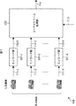
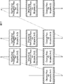
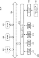
- the image encoding apparatus 100 shown in FIG. 1 has a plurality of input systems (multi-system input), encodes multi-system image data input from each input system, respectively, and generates a code stream.
- the code streams are integrated to generate one code stream.
- the image encoding apparatus 100 generates a code stream so as to have a progression function for realizing the expandability of the decoded image, such as JPEG2000 (Joint Photographic Experts Group 2000). That is, the image encoding device 100 generates a highly convenient code stream that can be used for various purposes.
- the image encoding apparatus 100 inputs X system image data.
- the image encoding device 100 includes an encoding unit 101-1 to encoding unit 101 -X, and a code stream generation unit 102.
- the encoding unit 101-1 through encoding unit 101-X encode X input image data (input image data 111-1 through input image data 111-X), respectively, and generate X code streams (code streams 112-1). To code stream 112-X).
- the code stream generation unit 102 receives the outputs (code stream 112-1 to code stream 112-X) of the encoding unit 101-1 to the encoding unit 101-X, and integrates them based on the designation 113 from the outside.
- One code stream is generated and output (code stream 114).
- the encoding unit 101 when it is not necessary to distinguish the encoding unit 101-1 to the encoding unit 101-X from each other, they are simply referred to as the encoding unit 101. Further, when it is not necessary to distinguish the input image data 111-1 to the input image data 111-X from each other, they are simply referred to as input image data 111. Further, when it is not necessary to distinguish the code streams 112-1 to 112-X from each other, they are simply referred to as a code stream 112.
- each encoding unit 101 generates a code stream 112 so as to have a progression structure that is a data structure for realizing the expandability of a decoded image with respect to image quality, resolution, and the like.
- the code stream generation unit 102 adds to the progression structure of the code streams 112, and further, the progression structure for multiple systems (data structure that realizes scalability related to the system, that is, which The code stream 114 is generated so as to have a data structure capable of controlling a system, which system is to be decoded, and in what order.
- the encoding unit 101 is provided in each system.
- one encoding unit 101 may be capable of encoding the input image data 111 of a plurality of systems.
- the image encoding apparatus 100 may include one encoding unit 101, and the encoding unit 101 may encode the X system input image data 111 and generate an X system code stream. .
- FIG. 2 is a block diagram illustrating a main configuration example of the encoding unit 101 of FIG.
- the encoding unit 101 is an encoder that performs encoding so as to generate a code stream having a progression structure similar to the JPEG2000 system.
- the encoding unit 101 may encode an image by the JPEG2000 method.
- the encoding unit 101 includes a DC level shift unit 131, a wavelet transform unit 132, a quantization unit 133, a code blocking unit 134, and a bit plane development unit 135.
- the DC level shift unit 131 performs a level shift of the DC component of the image data (input image data 111 in FIG. 1) input to the encoding unit 101 as indicated by an arrow 161 in order to efficiently perform the subsequent wavelet transform.
- the RGB signal has a positive value (unsigned integer). Therefore, the DC level shift unit 131 uses this fact to improve the compression efficiency by performing level shift that halves the dynamic range of the original signal. Therefore, this level shift is not performed when a signal having an integer value with a sign (both positive and negative) is used as the original signal, such as the color difference data Cb and the color difference data Cr of the YCbCr signal.
- the wavelet transform unit 132 is realized by a filter bank usually composed of a low-pass filter and a high-pass filter. Further, since a digital filter usually has an impulse response (filter coefficient) having a length of a plurality of taps, the wavelet transform unit 132 has a buffer that buffers an input image that can be filtered in advance.
- the wavelet transform unit 132 When the wavelet transform unit 132 acquires the image data output from the DC level shift unit 131 as indicated by an arrow 162 in an amount more than the minimum necessary for filtering, the wavelet transform unit 132 applies a predetermined amount to the image data after the DC level shift. Filtering is performed using a wavelet transform filter to generate wavelet coefficients. The wavelet transform unit 132 performs filtering for separating the image data into a low frequency component and a high frequency component for each of the vertical direction and the horizontal direction of the image.
- the wavelet transform unit 132 recursively repeats such filtering processing a predetermined number of times for subbands separated as low-frequency components in both the vertical direction and the horizontal direction. This is because, for example, as shown in FIG. 3, most of the energy of the image is concentrated in the low frequency component.
- FIG. 3 is a diagram illustrating a configuration example of a subband. As shown in FIG. 3, in both the division level number 1 state and the division level number 3 state, most of the energy of the image is concentrated in the low frequency component.
- FIG. 4 is a diagram illustrating a configuration example of subbands generated by the wavelet transform process with the number of division levels of 4.
- the wavelet transform unit 132 first filters the entire image to generate subbands 1LL (not shown), 1HL, 1LH, and 1HH. Next, the wavelet transform unit 132 performs filtering again on the generated subband 1LL to generate 2LL (not shown), 2HL, 2LH, and 2HH. Further, the wavelet transform unit 132 performs filtering again on the generated subband 2LL to generate 3LL, 3HL, 3LH, and 3HH. Further, the wavelet transform unit 132 performs filtering again on the generated subband 3LL to generate 4LL, 4HL, 4LH, and 4HH.
- the wavelet transform unit 132 supplies the wavelet coefficient obtained by filtering to the quantization unit 133 as indicated by an arrow 163 for each subband.
- the quantization unit 133 quantizes the supplied wavelet coefficients. This quantization method is arbitrary, but scalar quantization that divides by the quantization step size is common.
- the quantization unit 133 supplies the quantization coefficient obtained by the quantization to the code blocking unit 134 as indicated by an arrow 164. In the subsequent stage, a quantized coefficient is supplied instead of the wavelet coefficient. This quantized coefficient is also handled basically in the same manner as the wavelet coefficient. Accordingly, in the following description, unless necessary, the description thereof will be omitted, and simply referred to as a coefficient or coefficient data.
- the processing of the quantization unit 133 is omitted, as indicated by an arrow 165.
- the output of the wavelet transform unit 132 is supplied to the code block unit 134.
- the wavelet coefficients are divided by the code block forming unit 134 into code blocks having a predetermined size, which is a processing unit of entropy coding.
- FIG. 5 shows the positional relationship of code blocks in each subband. For example, a code block having a size of about 64 ⁇ 64 pixels is generated in all subbands after division. Each subsequent processing unit performs processing for each code block.
- the code block forming unit 134 supplies each code block to the bit plane developing unit 135 as indicated by an arrow 166.
- the bit plane expansion unit 135 expands the coefficient data into bit planes for each bit position.
- the bit plane is obtained by dividing (slicing) a coefficient group including a predetermined number of wavelet coefficients for each bit, that is, for each position. That is, the bit plane is a set of bits (coefficient bits) at the same position in the coefficient group.
- Fig. 6 shows a specific example.
- the left figure of FIG. 6 shows a total of 16 coefficients, 4 vertical and 4 horizontal. Among these 16 coefficients, the coefficient having the maximum absolute value is 13, which is expressed as 1101 in binary.
- the bit plane expansion unit 135 expands such a coefficient group into four bit planes indicating absolute values (absolute bit planes) and one bit plane indicating codes (sign bit planes). That is, the coefficient group on the left in FIG. 6 is expanded into four absolute value bit planes and one code bit plane, as shown on the right in FIG.
- all elements of the absolute value bit plane take values of 0 or 1.
- the bit plane element indicating the sign takes either a value indicating that the coefficient value is positive, a value indicating that the coefficient value is 0, or a value indicating that the coefficient value is negative.
- the encoding unit 101 further includes a bit modeling unit 136, an arithmetic encoding unit 137, a code amount adding unit 138, a rate control unit 139, a header generation unit 140, and a packet generation unit 141.
- the bit plane development unit 135 supplies the developed bit plane to the bit modeling unit 136 as indicated by an arrow 167.
- the bit modeling unit 136 and the arithmetic coding unit 137 operate as an EBCOT (Embedded Coding with Optimized Truncation) unit 151, and perform entropy coding called EBCOT defined in the JPEG2000 standard on the input coefficient data.
- EBCOT is a technique for performing coding while measuring the statistic of the coefficient in each block for each block of a predetermined size.
- the bit modeling unit 136 performs bit modeling on the coefficient data according to the procedure defined in the JPEG2000 standard, and as shown by an arrow 168, information such as control information, symbols, and context is sent to the arithmetic coding unit 137. Supply.
- the arithmetic encoding unit 137 performs arithmetic encoding on the bit plane of the coefficient.
- the vertical and horizontal size of the code block is a power of 2 from 4 to 256, and the sizes usually used are 32 ⁇ 32, 64 ⁇ 64, 128 ⁇ 32, and the like. It is assumed that the coefficient value is represented by an n-bit signed binary number, and bit 0 to bit (n ⁇ 2) represent respective bits from LSB to MSB. The remaining 1 bit indicates a sign.
- the coding of the code block is performed by the following three kinds of coding passes in order from the bit plane on the MSB side.
- Bit-plane (n-1) (MSB) is encoded by Cleanup Pass. Subsequently, the LSB side is sequentially moved, and each bit plane is encoded using three encoding passes in the order of SignificantSignPropagation Pass, Magnitude Refinement Pass, and Cleanup Pass.
- the first bit plane from the MSB side where 1 appears first is written in the header, and all 0 bit planes (referred to as zero bit planes) continuous from the MSB side are not encoded.
- encoding is performed by repeatedly using three types of encoding passes, and the encoding is terminated up to an arbitrary encoding pass of an arbitrary bit plane, thereby taking a trade-off between code amount and image quality (rate control is performed). ).
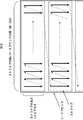
- the code block is divided into stripes every four coefficients in height.
- the stripe width is equal to the code block width.
- the scan order is the order in which all the coefficients in one code block are traced. In the code block, the order is from the upper stripe to the lower stripe, and in the stripe, from the left column to the right column. The order is from top to bottom in the sequence. All coefficients in the code block in each coding pass are processed in this scan order.
- Significance Propagation Pass In the Significance Propagation Pass that encodes a certain bit plane, the bit plane value of a non-significant coefficient in which at least one coefficient in the vicinity of 8 is significant is arithmetically encoded. When the encoded bit plane value is 1, whether the code is + or-is continued with MQ encoding.
- significance is the state that the encoder has for each coefficient, and the initial value of significance changes to 0 representing non-significant, and changes to 1 representing significant when 1 is encoded with that coefficient, and always thereafter. It will continue to be 1. Therefore, the significance can be said to be a flag indicating whether or not information of significant digits has already been encoded. If a bit plane becomes significant, it remains significant in subsequent bit planes.
- Magnitude Refinement Pass In the Magnitude Refinement Pass that encodes a bit plane, the Significance Propagation Pass that encodes a bit plane and the value of a bit plane of a significant coefficient that is not encoded are MQ-encoded.
- Cleanup Pass In the Cleanup Pass that encodes a bit plane, the value of the bit plane of a non-significant coefficient that is a Significance Pass that encodes a bit plane and that is not encoded is MQ encoded. When the value of the encoded bit plane is 1, whether the code is + or-(Sign information) is subsequently subjected to MQ encoding.
- MQ coding In the MQ coding in the above three coding passes, ZC (Zero Coding), RLC (Run-Length Coding), SC (Sign Coding), and MR (Magnitude Refinement) are used depending on the case. .
- MQ coding is a learning type binary arithmetic code defined by JBIG2 (reference: ISO / IEC FDIS 14492, “Lossy / Lossless Coding” of “Bi-level” Images, “March 2000”).
- the arithmetic encoding unit 137 supplies the generated code stream to the code amount adding unit 138 as indicated by an arrow 169.
- the code amount adding unit 138 counts and accumulates the code amount of the code stream.
- the code amount adding unit 138 supplies the code stream to the header creating unit 140 and the packet generating unit 141 as indicated by the arrows 172 and 173, and the code amount adding unit 138 as illustrated by the arrow 170.
- the accumulated value is supplied to the rate control unit 139.
- the rate control unit 139 controls the EBCOT unit 151 based on the supplied accumulated value of the code amount, as shown by an arrow 171, and ends the encoding when the accumulated value reaches the target code amount. That is, the rate control unit 139 controls the amount of generated code (code stream rate control).
- the packet generation unit 141 packetizes the supplied code stream.
- the header generation unit 140 generates header information of the packet and supplies the header information to the packet generation unit 141 as indicated by an arrow 174.
- the packet generation unit 141 performs packetization using the header information.
- FIG. 9 The concept of this packet is shown in FIG.
- the example shown in FIG. 9 is an example in which wavelet transformation is performed three times, and as a result, four packets from the lowest packet 1 to the highest packet 4 are generated. Therefore, the encoded code streams of all the code blocks existing in the subbands in these individual packets are packed for each packet.
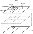
- FIG. 10 illustrates a case where the coding pass is divided into L layers, layer 1 to layer L.
- the leading coding pass of layer n is located immediately after the last trailing coding pass of layer (n ⁇ 1). Therefore, the code amount of the code stream increases as the number of layers increases. That is, the image quality of the decoded image is improved (the resolution does not change).
- image quality of the decoded image can be controlled by controlling from which layer 1 to which layer is decoded during decoding.
- image quality indicates the visual quality of a decoded image depending on this layer (that is, the amount of information of each pixel).
- the generated packet is output to the outside of the encoding unit 101 and supplied to the code stream generating unit 102 as indicated by an arrow 175.
- Each encoding unit 101 encodes image data by the JPEG2000 system as described above, and generates a codestream having a JPEG2000 progression function for resolution, layer, and the like.
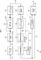
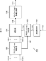
- FIG. 11 is a block diagram illustrating a main configuration example of the code stream generation unit 102 of FIG. As illustrated in FIG. 11, the code stream generation unit 102 includes a progression analysis unit 181, a designation reception unit 182, a progression determination unit 183, an integration unit 184, and a progression information generation unit 185.
- the code stream generation unit 102 includes a progression analysis unit 181, a designation reception unit 182, a progression determination unit 183, an integration unit 184, and a progression information generation unit 185.
- the progression analysis unit 181 analyzes the progression structure for each of the input code streams 112-1 to 112-X, and identifies what structure each code stream is configured with.
- the progression analysis unit 181 supplies the analyzed code streams 191-1 to 191-X to the integration unit 184. Further, the progression analysis unit 181 supplies the analysis result of each code stream to the progression determination unit 183 (arrow 192).
- code streams 191-1 to 191-X are simply referred to as a code stream 191 when there is no need to distinguish them from each other.
- the designation receiving unit 182 receives, for example, designation 113 of the progression structure of the integrated code stream supplied from the outside, such as a user or another device, and supplies it to the progression determining unit 183 (arrow 192).
- the progression determination unit 183 determines the progression structure of the integrated code stream based on the analysis result supplied from the progression analysis unit 181 and the designation from the outside supplied from the designation receiving unit 182, and the information This is supplied to the integration unit 184 (arrow 194).
- the progression determination unit 183 may determine the progression structure using not only the analysis result and designation from the outside but also other information as appropriate.
- the integration unit 184 Based on the information on the progression structure supplied from the progression determination unit 193, the integration unit 184 has a progression analysis unit so that the integrated code stream has a progression structure for each system in addition to the resolution and image quality. Each code stream supplied from 181 is integrated. The integration unit 184 supplies the integrated single code stream 195 to the progression information generation unit 185.
- the progression information generation unit 185 generates progression information that is information related to the progression structure of the code stream 194, and embeds the progression information in a predetermined position of the integrated code stream 194 such as header information.
- the progression information generator 185 outputs the code stream 114 with the progression information added.
- JPEG2000 Progression As characteristics in JPEG2000 encoding, there are a bit plane and a subband generated by wavelet transform. These allow definition of progression.
- Progression is the order of codewords belonging to the same category. For example, if code words of different layers belonging to the same resolution level are collected, images having the same image size and different image quality can be generated. Conversely, by collecting codewords of different resolution levels belonging to the same layer, it is possible to generate images having the same image quality but different image sizes. That is, it is a data structure for realizing the expandability of the decoded image.
- JPEG2000 In JPEG2000, only a part of data can be decoded from a code stream for a predetermined element in this way. Accordingly, various decoded images can be easily obtained from one code stream. In other words, by providing the code stream with such a progression structure, the code stream can be used for various purposes, and the convenience of the code stream is improved.
- a high-performance liquid crystal display rich in expressive power on a large screen from one code stream a high-resolution and high-bit-rate decoded image is provided, and a small-screen mobile phone with low image processing capability
- a decoded image with a low resolution and a low bit rate can be easily realized by selecting a progression element such as a layer or a subband to be decoded.
- Such a progression structure can be used not only in the decoding process but also in a conversion process (transcoding) for changing the image size, image quality, etc. of the decoded image. That is, as in the decoding process described above, a code stream in which the image size and the image quality of a decoded image are changed can be easily generated by simply selecting a progression element such as a layer or subband (ie, transcoding). can do.
- a progression element such as a layer or subband (ie, transcoding).
- the resolution level is a level generated along with the wavelet transform as illustrated in FIG. That is, the resolution level defines the image size of the decoded image.
- the layer is an element that affects the image quality at the level in the bit plane direction.
- a component is defined when it is composed of different components such as YCbCr (the number of components is 3 in the case of YCbCr and RGB).
- the position relates to one of the features of JPEG2000, and defines the number and position of each tile when the screen is divided and encoded into a plurality of rectangular blocks.
- LRCP Layer Resolution-level Component Position Progression
- RLCP Resolution-level Layer Component Position Progression
- RPCL Resolution-level Position Component Component Layer
- PCRL Purponent Position-Resolution-level Layer
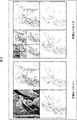
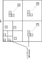
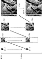
- FIG. 12 shows a decoded image generated when an encoded code stream in which JPEG2000 codewords are arranged in the order of LRCP is decoded in that order.
- the code words are arranged so that the lowest layer is the position. In the following, description of the position (P) is omitted. *
- the decoded image is displayed so that the image quality is gradually improved as in the order of image 201, image 202, image 203, and image 204 shown in FIG.
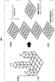
- FIG. 13 shows a decoded image generated when an encoded code stream in which JPEG2000 codewords are arranged in the order of RLCP is decoded in that order.
- packets are arranged in the following order. That is, the codewords are arranged so that the highest layer is the resolution level, the next lower layer is the layer, the next lower layer is the component, and the lowest layer is the position. In the following, description of the position (P) is omitted.
- the decoded image gradually increases in image size (resolution) as shown in the order of image 211, image 212, image 213, and image 214 shown in FIG. Is displayed.
- the order of the decoding process of the code stream differs depending on the hierarchical structure of each element of the progression, and the display method of the decoded image also changes.
- other RPCL, PCRL, and CPRL are also subjected to decoding processing in the order corresponding to each hierarchical structure.
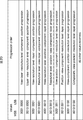
- FIG. 14 is a diagram showing an example of SGcod parameters, which are parameters for coding style, defined in Table A-14 of the JPEG2000 Part-1 draft. It is possible to define the above-mentioned progression order by Progression order (8 bits) in SGcod.
- the code stream 112 supplied to the code stream generation unit 102 in FIG. 1 has a JPEG2000 progression structure as described above.
- the code stream generation unit 102 expands this progression structure, and adds a progression structure for multiple systems (a progression structure that realizes system scalability) to the conventional structure.
- the code streams are integrated to generate one code stream. An example of the hierarchical structure of the progression after integration will be described below.
- the first example of the hierarchical structure is XLRCP in which the highest hierarchy is a system and the following hierarchy is LRCP.
- the decoded image is decoded and displayed one by one in order as shown in FIG. That is, the XLRCP codestream is first decoded from layer 1 to layer N as in the image 201-1, the image 202-1, the image 203-1, and the image 204-1 for the first system (gradually). To improve the image quality).
- each system is decoded one by one, and finally, for the Xth system, layers 1 to N are decoded as in image 201-X, image 202-X, image 203-X, and image 204-X. (The image quality gradually improves.)
- the code stream generation unit 102 uses the code stream having such an XLRCP structure. Is generated as follows.
- the variable v indicates the number of views (number of input systems X) (VLRCP).
- Multi-view can generate 3D video with a wide viewing angle by increasing the number of cameras, and can extract images in the depth direction much more easily than stereo.
- many research institutions are also examining techniques for interpolating and synthesizing arbitrary viewpoint images between cameras.
- the code stream generation unit 102 uses the following code stream having such an XLRCP structure. Generate as follows. In the following, the variable s indicates the system (left or right) (SLRCP). In the following, description of the position (P) is omitted.
- the second example of the hierarchical structure is LXRCP with the second hierarchy of LRCP as a system.
- the decoded image is decoded and displayed one layer at a time as shown in FIG. That is, the LXRCP code stream is first decoded in order from the first system to the X-th system for the first system, such as the image 201-1, the image 201-2,..., The image 201-X. (X layer 1 images are generated).
- X decoded images of layer 1 are obtained, next, with respect to layer 2, the first system to the Xth system, such as image 202-1, image 202-2,. Are sequentially decoded (X layer 2 images are generated).
- the first system to the Xth system are sequentially decoded as in the image 203-1, the image 203-2,... Layer 3 image is generated).
- each layer is decoded, and finally, for the layer L, from the first system to the Xth system as in the image 204-1, the image 204-2,..., The image 204-X. Decoded in order (images of X layers L are generated).
- the image quality of the stereo image is gradually improved on the receiving side (decoding side). Suitable for application.
- the code stream generation unit 102 uses the code stream having such an LXRCP structure. Is generated as follows. In the following, the variable v indicates the number of views (number of input systems X) (LVRCP). In the following, description of the position (P) is omitted.
- the code stream generation unit 102 uses the following code stream having such an LXRCP structure. Generate as follows. In the following, the variable s indicates the system (left or right) (LSRCP). In the following, description of the position (P) is omitted.
- XRLCP A third example of the hierarchical structure is XRLCP in which the highest hierarchy is a system and the following hierarchy is RLCP.
- the decoded image is decoded and displayed one by one in order as shown in FIG.
- the XRLCP code stream first has the resolution of the lowest hierarchy from the resolution level of the lowest layer, such as image 211-1, image 212-1, image 213-1 and image 214-1, for the first system. Up to the level is decoded (the image size gradually increases).
- the second system and subsequent systems are similarly decoded one by one.
- the image 211-X, the image 212-X, and the image 213 are decoded.
- the resolution level from the lowest layer to the resolution level of the highest hierarchy is decoded (the image size gradually increases).
- the code stream generation unit 102 uses the following code stream having such an XLRCP structure. Generate as follows. In the following, the variable s indicates the system (left or right) (SRLCP). In the following, description of the position (P) is omitted.
- RXLCP The fourth example of the hierarchical structure is RXLCP with the second hierarchy of RLCP as a system.
- the decoded image is decoded and displayed in order by one resolution level. That is, the RXLCP codestream is first decoded in order from the first system to the Xth system, such as the image 211-1,... X bottom layer resolution level images are generated).
- the third resolution level from the bottom is similarly decoded in order from the first system to the Xth system as in the image 213-1,.
- the third resolution level image from the bottom is generated).
- the resolution level is decoded one by one.
- the resolution level of the highest layer is changed from the first system to the Xth system as in the image 214-1,..., The image 214-X. Decoded sequentially (X top layer resolution level images are generated).
- the code stream generation unit 102 uses the code stream having such an RXLCP structure. Is generated as follows. In the following, the variable v indicates the number of views (number of input systems X) (RVLCP). In the following, description of the position (P) is omitted.
- the progression information generation unit 185 sets the Progression order of the SGcod parameter existing in the tile part header or main header of one system code stream 195 integrated by the integration unit 184 to a value corresponding to the progression structure of the code stream 195. To do.
- the lower 4 bits can maintain compatibility with the conventional JPEG2000. Affinity can be increased. Therefore, for example, in a conventional JPEG2000 decoder that does not support such an extension, it can be decoded as a hierarchical structure of four elements according to the lower 4 bits.
- Rsiz Denotes capabilities that a decoder needs toproperly decode the codestream.
- step S101 each encoding unit 101 encodes the image data 111 input from the input system corresponding to itself.
- step S102 the image coding apparatus 100 determines whether or not the input images of all systems have been encoded. If it is determined that there are unprocessed systems, the process returns to step S101, and all the systems Wait until it is determined that the input image has been processed.
- step S102 when it is determined that the input images of all systems have been encoded, the image encoding device 100 advances the process to step S103.
- step S103 the code stream generation unit 102 integrates the code streams of the respective systems, and generates a single system code stream having a progression function.
- the image encoding device 100 ends the multi-system input encoding process.
- step S121 the DC level shift unit 131 shifts the DC level of the image data input from the corresponding input system.
- the wavelet transform unit 132 performs wavelet transform on the image data whose DC level has been shifted.
- step S124 the code blocking unit 134 divides the quantized coefficient in units of code blocks.
- step S125 the bit plane expansion unit 135 expands the coefficient for each code block into a bit plane.
- step S126 the EBCOT unit 151 encodes the coefficient expanded in the bit plane.
- step S127 the rate control unit 139 controls the rate of the generated code amount using the code amount and the like added by the code amount adding unit 138.
- step S130 When the process of step S130 is finished, the encoding process is finished. This encoding process is repeatedly executed for each predetermined data unit until the supply of image data is completed or an instruction for termination is received. Further, this encoding process is executed in each encoding unit 101.
- the encoding unit 101 can encode the input images of each system so as to have a progression structure that is a data structure for realizing the expandability of the decoded image.
- the code stream generation unit 102 starts a code stream generation process.
- the progression analysis unit 181 analyzes the progression for all the code streams supplied from each encoding unit 101 in step S151.
- step S152 the designation receiving unit 182 receives a designation related to the progression structure after the code stream integration supplied from, for example, a user or an external device.
- step S153 the progression determination unit 183 determines the progression structure of the integrated code stream based on the analysis result obtained by the process of step S151 and the external designation received by the process of step S152.
- step S154 the integration unit 184 integrates the code streams of the respective systems so as to have the progression structure determined in step S153.
- the progression information generation unit 185 generates the progression information of the integrated code stream, and the progression information is generated at a predetermined position of the integrated code stream such as Progression order in SGcod or Rsiz of the SIZ marker. Add information.
- step S156 the progression information generation unit 185 outputs a code stream.
- the code stream generation unit 102 has a structure in which the code stream of each system is added to the progression structure of each code stream with a progression structure for multiple systems (a data structure that realizes system scalability). Can be integrated into. By doing in this way, the image coding apparatus 100 can encode a multi-system input image, realize the expandability of the decoded image, and generate a code stream that can be used for various purposes.
- the image decoding apparatus for decoding the code stream is based on the progression information added to the code stream.
- the code stream can be easily decoded.
- the image encoding device 100 can improve the convenience of a code stream in which multi-line images are encoded.
- the progression information may be provided to the decoding side as data different from the code stream. In this case, however, it is necessary to clarify the correspondence between the code stream and the progression information (so that the correspondence can be grasped on the decoding side).
- FIG. 26 is a block diagram illustrating a main configuration example of an image decoding device to which the present invention has been applied.
- the image decoding apparatus 300 can decode a code stream according to a progression structure, which is a data structure for realizing the expandability of the decoded image, included in the input code stream, and can obtain a multi-system decoded image. .
- a progression structure which is a data structure for realizing the expandability of the decoded image, included in the input code stream.
- the image decoding apparatus 300 decodes only necessary information in accordance with the progression structure of the input code stream, and the decoded image (decoded image corresponding to the application) whose image quality, image size, etc. are appropriate for the application. ) May be obtained.
- the image decoding apparatus 300 includes a code stream analysis unit 301, and decoding units 302-1 to 302-X.
- the code stream analysis unit 301 analyzes the progression structure of the code stream 311 based on the progression information added to the input code stream 311 and the number of systems (number of views) X before the code stream 311 is integrated. Into the code stream.
- the code stream analysis unit 301 supplies the separated code stream 312-1 to code stream 312-X to the decoding unit 302-1 to decoding unit 302-X corresponding to each system.
- Each of the decoding units 302-1 to 302-X decodes the input code stream by a method corresponding to the encoding unit 101 in FIG. 1, and decodes the decoded image data 313-1 to decoded image 313-X. Generate and output.
- the decoding units 302-1 to 302-X are simply referred to as the decoding unit 302 when it is not necessary to distinguish between them.
- the code streams 312-1 to 312-X are simply referred to as code streams 312 when there is no need to distinguish them from each other.
- the decoding unit 302 is provided in each system. However, one decoding unit 302 may be able to decode the code streams 312 of a plurality of systems.
- the image decoding apparatus 300 may include one decoding unit 302, and the decoding unit 302 may decode the X system code stream 312 to generate the X system decoded image data 313. .
- FIG. 27 is a block diagram illustrating a main configuration example of the code stream analysis unit 301 of FIG. As illustrated in FIG. 27, the code stream analysis unit 301 includes a progression analysis unit 321, a division unit 322, and a progression information generation unit 323.
- the progression analysis unit 321 analyzes the progression information added to the input code stream 311 and analyzes the progression structure of the code stream 311. For example, the progression analysis unit 321 refers to the Progress order in the SGcod described in the main header and tile part header of the code stream 311 and Rsiz of the SIZ marker, and grasps the progression structure of the code stream 311 and the number of views. The progression analysis unit 321 supplies the analyzed code stream 331 and the analysis result 332 to the division unit 322.
- the dividing unit 322 Based on the analysis result of the progression supplied from the progression analysis unit 321, the dividing unit 322 has a progression structure (data that realizes scalability related to the system) included in the code stream 331 supplied from the progression analysis unit 321. Based on the structure), the code stream 331 that was one system is separated into X code streams before integration.
- encoded data for each predetermined unit is arranged according to the order of the progression structure.
- the dividing unit 322 switches the decoding unit 302 that is the supply destination of the code stream 331 according to the progression structure for multiple systems among the progression structures that the code stream 331 has.
- the dividing unit 322 supplies the separated code stream 333-1 to code stream 333-X to the progression information generating unit 323.
- the progression information generation unit 323 generates progression information indicating a progression structure for each of the code streams 333-1 to 333-X, and places the progression information at predetermined positions of the code streams 333-1 to 333-X. Append.
- code streams 333-1 to 333-X are simply referred to as code streams 333 when there is no need to distinguish them from each other.
- FIG. 28 is a block diagram illustrating a main configuration example of the decoding unit 302.
- the decoding unit 302 corresponds to the encoding unit 101 in FIG. 1 and decodes the code stream generated by encoding by the encoding unit 101.
- the decoding unit 302 includes a packet decoding unit 351, an arithmetic decoding unit 352, a bit modeling unit 353, a bit plane synthesis unit 354, a code block synthesis unit 355, a wavelet inverse transformation unit 356, and a DC level inverse unit.
- a shift unit 357 is included.
- the packet decoding unit 351 decodes the packet supplied from the image encoding device 100 as indicated by the arrow 361 and supplies the code stream to the arithmetic decoding unit 352 as indicated by the arrow 362.
- the arithmetic decoding unit 352 and the bit modeling unit 353 operate as the EBCOT unit 371, and perform entropy decoding called EBCOT defined by, for example, the JPEG2000 standard on the input code stream.
- the arithmetic decoding unit 352 decodes the code stream by a method corresponding to the arithmetic encoding unit 137 and supplies the context to the bit modeling unit 353 as indicated by an arrow 363.
- the bit modeling unit 353 generates wavelet coefficients expanded on the bit plane by a method corresponding to the bit modeling unit 136.
- the bit modeling unit 353 supplies the generated coefficient data for each bit plane to the bit plane synthesis unit 354 as indicated by an arrow 364.
- the bit plane synthesis unit 354 synthesizes the wavelet coefficients expanded on the bit plane.
- the bit plane synthesis unit 354 supplies the wavelet coefficients obtained by synthesizing the bit planes to the code block synthesis unit 355 as indicated by an arrow 365.
- the code block synthesis unit 355 generates coefficient data in units of code blocks using the supplied bit plane, and further synthesizes them to generate coefficient data for each subband.
- the code block synthesis unit 355 supplies it to the wavelet inverse transformation unit 356 as indicated by an arrow 366.
- the wavelet inverse transform unit 356 performs wavelet inverse transform on the supplied wavelet coefficients to generate baseband image data.
- the wavelet inverse transform unit 356 supplies the generated baseband image data to the DC level inverse shift unit 357 as indicated by an arrow 367.
- each code stream 312 encoded data for each predetermined unit is arranged in an order according to the progression structure. Therefore, the decoding unit 302 can decode the code stream 312 in the order according to the progression structure included in the code stream 312 by sequentially decoding the input code stream 312.
- the image decoding apparatus 300 performs multi-system output decoding processing to decode a code stream in which multi-system images are integrated. First, an example of the flow of this multi-system output decoding process will be described with reference to the flowchart of FIG.
- the image decoding apparatus 300 acquires the code stream generated by the image encoding apparatus 100, the image decoding apparatus 300 starts multi-system output decoding processing.
- the code stream analysis unit 301 analyzes the acquired code stream and separates the code stream into code streams of the number of systems before integration.
- the progression analysis unit 321 analyzes the progression information added to the code stream in step S321, and grasps the progression structure of the code stream, the number of views, and the like.
- step S322 the dividing unit 322 separates the code stream for each system according to the progression structure of the code stream analyzed by the process of step S321.
- step S323 the progression information generation unit 323 generates and adds progression information for each of the separated code streams.
- step S324 the progression information generation unit 323 outputs the code stream of each system to which the progression information is added.
- step S324 the code stream analysis unit 301 ends the analysis process, returns the process to step S301 in FIG. 29, and executes the processes in and after step S302.
- the packet decoding unit 351 extracts encoded data from the acquired packet in step S341.
- step S342 the EBCOT unit 371 decodes the encoded data extracted in step S341.
- step S343 the bit plane combining unit 354 combines the bit planes of the coefficient data obtained by the decoding, and generates coefficient data for each code block.
- step S344 the code block synthesis unit 355 synthesizes code blocks of coefficient data for each code block, and generates coefficient data for each subband.
- step S345 the wavelet inverse transform unit 356 performs wavelet inverse transform on the coefficient data for each subband to generate baseband image data. Note that, when the coefficient data is quantized in the image encoding device 100, inverse quantization corresponding to the quantization is performed on the coefficient data, and then the wavelet inverse transform is performed.
- step S346 the DC level reverse shift unit 357 reversely shifts the DC level of the baseband image data obtained by the inverse wavelet transform.
- step S347 the decoding unit 302 outputs the image data subjected to the DC level reverse shift process from the output system 368 as decoded image data.
- the decoded image data is output to a display (not shown), for example, and the image is displayed.
- the decoding unit 302 ends the decoding process.
- the decoding unit 302 repeats such decoding processing for each decoding processing unit. Since each encoded data is arranged in the order corresponding to the progression structure in the code stream, the decoding unit 302 can easily decode the code stream by sequentially decoding the supplied encoded data according to the progression information. Decoding can be performed in the order according to the progression structure.
- the image decoding apparatus 300 analyzes the progression information added to the code stream, thereby performing decoding according to the progression structure, which is a data structure for realizing the extensibility of the decoded image.
- System decoded image data can be generated. That is, the image decoding apparatus 300 can appropriately decode the code stream generated by the image encoding apparatus 100 and realize the expandability of the decoded image. Therefore, the image decoding apparatus 300 can improve the convenience of the code stream in which multi-line images are encoded.
- a method of extracting this depth data from a plurality of image data is considered. That is, a certain subject is photographed from a plurality of directions, and the position of the subject in the depth direction is calculated from the difference in the position of the subject in each captured image. By such a method, the depth direction position is obtained for all subjects in the captured image, and depth data is generated.
- the position of the subject in the depth direction in the image can be specified, and therefore binocular parallax from an arbitrary viewpoint can be calculated based on the information. That is, a stereo image from an arbitrary viewpoint can be generated.
- depth data may be encoded as one system, and may be encoded together with image data to form a single system code stream so as to have a progression structure.
- the present invention encodes such depth data as an input of a single system.
- the present invention can also be applied to a case where a single code stream having a progression structure is used.
- FIG. 32 is a block diagram showing a configuration example of the image encoding device in that case. 32, the same number is attached
- an image encoding device 400 basically has the same configuration as the image encoding device 100, but further includes a depth data generation unit 411 and an encoding unit 412.
- the input image data 111 of each input system is an image in which substantially the same subject is photographed or drawn from different directions, that is, an image constituting a multiview.
- the depth data generation unit 411 uses each input image data 111 to generate depth data 421 indicating the position of the subject in the depth direction in the image.
- the method for calculating the position of the subject in the depth direction is arbitrary.
- FIG. 33 shows an example of depth data.
- An example of the depth data of the image data 111 shown in FIG. 33A is shown in FIG.
- the depth data 421 is information indicating the position in the depth direction of the entire area of the image data 111 with a predetermined number of bits for each predetermined range, for example, for each pixel or each block. It is. That is, the depth data 421 can be generally expressed as grayscale bitmap data. The number of gradations of the bitmap data becomes the bit depth of the depth data 421 (that is, the ability to express the position in the depth direction).
- this depth data can be encoded basically in the same manner as the other input image data 111.
- the depth data generation unit 411 supplies the generated depth data 421 to the encoding unit 412.
- the encoding unit 412 has the same configuration as the encoding unit 101 and performs the same processing. That is, the encoding unit 412 encodes the depth data 421 in the same manner as the encoding unit 101, and generates a code stream 422 having a progression structure such as JPEG2000. The encoding unit 412 supplies the generated code stream 422 to the code stream generation unit 102.
- the code stream generation unit 102 integrates the code streams of the respective systems as in the case of the first embodiment, and generates a single system code stream 114 having a progression structure including a progression structure for multiple systems. To do.
- the depth data may be generated outside the image encoding device 400.
- the image encoding device 400 has the same configuration as the image encoding device 100 of FIG. That is, when image data and depth data are input, the image encoding device 100 can encode them.
- step S401 and step S402 in FIG. 34 are executed similarly to step S101 and step S102 in FIG.
- step S403 the depth data generation unit 411 generates depth data from the input image data 111 of each system.
- step S404 the encoding unit 412 encodes the depth data in the same manner as in step S401.
- step S405 the code stream generation unit 102 integrates the code stream generated in step S401 and the code stream generated in step S404 in the same manner as in step S103 in FIG. 23, and has a progression structure. Generate a system codestream.
- step S405 the image encoding device 400 ends the multi-system input encoding process.
- the image encoding device 400 generates depth data from multi-line input image data constituting a multi-view, encodes the input image data of each line along with the depth data, and has one line having a progression structure.
- a code stream can be generated.
- the image encoding device 400 can improve the convenience of a code stream in which images of multiple systems are encoded even when the depth data is included in this way.
- the depth data can be processed as one system of image data (bitmap data). That is, the image decoding apparatus 300 described in the second embodiment can also decode the code stream 114 generated by the image encoding apparatus 400 in the same manner as the code stream 114 generated by the image encoding apparatus 100. it can.
- the code stream generated by the image encoding device 100 or the image encoding device 400 described above may be transferred to the image decoding device 300 by any method.
- the image encoding apparatus 100 or the image encoding apparatus 400 records the generated code stream on an arbitrary recording medium such as a Blu-Ray Disc, a flash memory, or a hard disk, and the image decoding apparatus 300 records the recording medium.
- the code stream may be read from and decoded.
- the image encoding device 100 or the image encoding device 400 may transmit the generated code stream to the image decoding device 300 via an arbitrary communication medium such as a wired or wireless network.
- the code stream generation unit 102 of the image encoding device 100 and the image encoding device 400 has been described as acquiring the designation 113 from the outside regarding the progression structure, but the provider of this designation is arbitrary It is. For example, it may be supplied from a user or another device as described above. Further, it may be supplied from an image decoding device that decodes a code stream generated by the image encoding device.
- FIG. 35 is a block diagram showing a configuration example of a network system to which the present invention is applied.
- a network system 500 shown in FIG. 35 is a system that transmits multi-line image data from the transmission side to the reception side via the network 501. At that time, in order to reduce the bandwidth used at the time of transmission, the network system 500 encodes multi-line image data on the transmission side, and transmits the data as a single code stream, and decodes it on the reception side. The original multi-system decoded image data is obtained.
- the network 501 is composed of an arbitrary communication medium.
- the network 501 is configured by an arbitrary network represented by the Internet, a LAN, or the like.
- the network 501 may be a single network or a collection of a plurality of networks. Therefore, the network 501 may include an arbitrary communication device such as a repeater in addition to a communication medium such as a cable.
- the network 501 may be a wired network, a wireless network, or a mixture of wired and wireless.
- the network system 500 includes the above-described image encoding device 100 as an encoding device on the transmission side.
- the network system 500 includes the above-described image decoding device 300 as a receiving-side decoding device.
- the transmitting-side image encoding device 100 encodes multi-channel image data to be transmitted, generates a single-system code stream 114 having a progression structure, and transmits it to the image decoding device 300 via the network 501. To do.
- the image decoding apparatus 300 on the receiving side receives it as a code stream 311, decodes it, separates it into original multi-system image data, and outputs it.
- the image decoding apparatus 300 provides the designation 511 relating to the progression structure to the image encoding apparatus 100 via the network 501 based on the usage method of the image data.
- the code stream generation unit 102 of the image encoding device 100 accepts this as an external designation 113.
- the image encoding device 100 can easily generate a code stream having a progression structure according to the use on the reception (decoding) side. That is, the network system 500 can improve the convenience of a code stream in which images of multiple systems are encoded.
- the designation relating to the progression structure is performed by a device other than the image decoding device 300, for example, a control center or a relay hub included in the network 501 based on the bandwidth of the network 501 or the congestion status (image coding device 100). May be provided).
- the image data encoding method is not limited to the JPEG2000 method.
- a CPU (Central Processing Unit) 601 of the personal computer 600 performs various processes according to a program stored in a ROM (Read Only Memory) 602 or a program loaded from a storage unit 613 into a RAM (Random Access Memory) 603. Execute the process.
- the RAM 603 also appropriately stores data necessary for the CPU 601 to execute various processes.
- the CPU 601, ROM 602, and RAM 603 are connected to each other via a bus 604.
- An input / output interface 610 is also connected to the bus 604.
- the input / output interface 610 includes an input unit 611 including a keyboard and a mouse, a display such as a CRT (Cathode Ray Tube) display and an LCD (Liquid Crystal Display), an output unit 612 including a speaker, an SSD (Solid).
- a storage unit 613 made up of State Drive) and a hard disk, and a communication unit 614 made up of a wired LAN (Local Area Network), wireless LAN interface, modem, and the like are connected.
- the communication unit 614 performs communication processing via a network including the Internet.
- a drive 615 is connected to the input / output interface 610 as necessary, and a removable medium 621 such as a magnetic disk, an optical disk, a magneto-optical disk, or a semiconductor memory is appropriately mounted, and a computer program read from them is loaded. It is installed in the storage unit 613 as necessary.
- a program constituting the software is installed from a network or a recording medium.
- the recording medium is distributed to distribute the program to the user separately from the apparatus main body, and includes a magnetic disk (including a flexible disk) on which the program is recorded, an optical disk ( It only consists of removable media 621 consisting of CD-ROM (compact disc-read only memory), DVD (including digital versatile disc), magneto-optical disc (including MD (mini disc)), or semiconductor memory. Rather, it is configured by a ROM 602 that stores a program and a hard disk included in the storage unit 613, which is distributed to the user in a state of being incorporated in the apparatus main body in advance.
- the program executed by the computer may be a program that is processed in time series in the order described in this specification, or in parallel or at a necessary timing such as when a call is made. It may be a program for processing.
- the step of describing the program recorded on the recording medium is not limited to the processing performed in chronological order according to the described order, but may be performed in parallel or It also includes processes that are executed individually.
- system represents the entire apparatus composed of a plurality of devices (apparatuses).
- the configuration described above as one device (or processing unit) may be configured as a plurality of devices (or processing units).
- the configuration described above as a plurality of devices (or processing units) may be configured as a single device (or processing unit).
- a configuration other than that described above may be added to the configuration of each device (or each processing unit).
- a part of the configuration of a certain device (or processing unit) may be included in the configuration of another device (or other processing unit). Good. That is, the embodiment of the present invention is not limited to the above-described embodiment, and various modifications can be made without departing from the gist of the present invention.
- the code stream generation unit 102 in FIG. 1 may be an independent device, and multiple code streams may be input and integrated to be output as a single code stream having a progression structure. Good.
- the present invention includes, for example, an editing device for 3D digital cinema, a 3D archive system, a 3D image transmission device of a broadcasting station, a 3D image database, a 3D medical image recording system, a 3D game machine, a television receiver system, and a 3D compatible BluBRay.
- the present invention can be applied to an authoring tool installed in a disc recorder or player, a free viewpoint television, a realistic video conference system, a personal computer, or the like, or a software module thereof.
Landscapes
- Engineering & Computer Science (AREA)
- Multimedia (AREA)
- Signal Processing (AREA)
- Compression Or Coding Systems Of Tv Signals (AREA)
- Compression Of Band Width Or Redundancy In Fax (AREA)
Priority Applications (5)
| Application Number | Priority Date | Filing Date | Title |
|---|---|---|---|
| BR112012004815A BR112012004815A2 (pt) | 2010-07-09 | 2011-07-01 | aparelho de processamento de imagem, e, método de processamento de imagem para um aparelho de processamento de imagem |
| CN2011800036811A CN102484674A (zh) | 2010-07-09 | 2011-07-01 | 图像处理装置和方法 |
| RU2012108119/08A RU2012108119A (ru) | 2010-07-09 | 2011-07-01 | Устройство и способ обработки изображений |
| EP11803527A EP2458841A1 (en) | 2010-07-09 | 2011-07-01 | Image processing device and method |
| US13/393,935 US8953898B2 (en) | 2010-07-09 | 2011-07-01 | Image processing apparatus and method |
Applications Claiming Priority (2)
| Application Number | Priority Date | Filing Date | Title |
|---|---|---|---|
| JP2010-156708 | 2010-07-09 | ||
| JP2010156708A JP5392199B2 (ja) | 2010-07-09 | 2010-07-09 | 画像処理装置および方法 |
Publications (1)
| Publication Number | Publication Date |
|---|---|
| WO2012005193A1 true WO2012005193A1 (ja) | 2012-01-12 |
Family
ID=45441172
Family Applications (1)
| Application Number | Title | Priority Date | Filing Date |
|---|---|---|---|
| PCT/JP2011/065208 WO2012005193A1 (ja) | 2010-07-09 | 2011-07-01 | 画像処理装置および方法 |
Country Status (7)
| Country | Link |
|---|---|
| US (1) | US8953898B2 (pt) |
| EP (1) | EP2458841A1 (pt) |
| JP (1) | JP5392199B2 (pt) |
| CN (1) | CN102484674A (pt) |
| BR (1) | BR112012004815A2 (pt) |
| RU (1) | RU2012108119A (pt) |
| WO (1) | WO2012005193A1 (pt) |
Cited By (1)
| Publication number | Priority date | Publication date | Assignee | Title |
|---|---|---|---|---|
| CN115022715A (zh) * | 2020-06-04 | 2022-09-06 | 腾讯科技(深圳)有限公司 | 一种沉浸媒体的数据处理方法及设备 |
Families Citing this family (35)
| Publication number | Priority date | Publication date | Assignee | Title |
|---|---|---|---|---|
| GB0516549D0 (en) | 2005-08-12 | 2005-09-21 | Sulaiman Brian | Milling system |
| US8866920B2 (en) | 2008-05-20 | 2014-10-21 | Pelican Imaging Corporation | Capturing and processing of images using monolithic camera array with heterogeneous imagers |
| US11792538B2 (en) | 2008-05-20 | 2023-10-17 | Adeia Imaging Llc | Capturing and processing of images including occlusions focused on an image sensor by a lens stack array |
| EP2502115A4 (en) | 2009-11-20 | 2013-11-06 | Pelican Imaging Corp | RECORDING AND PROCESSING IMAGES THROUGH A MONOLITHIC CAMERA ARRAY WITH HETEROGENIC IMAGE CONVERTER |
| US8878950B2 (en) | 2010-12-14 | 2014-11-04 | Pelican Imaging Corporation | Systems and methods for synthesizing high resolution images using super-resolution processes |
| JP5770378B2 (ja) * | 2011-09-08 | 2015-08-26 | モトローラ モビリティ エルエルシーMotorola Mobility Llc | 係数の矩形ブロックを量子化及び逆量子化するための方法及び機器 |
| KR102002165B1 (ko) | 2011-09-28 | 2019-07-25 | 포토내이션 리미티드 | 라이트 필드 이미지 파일의 인코딩 및 디코딩을 위한 시스템 및 방법 |
| US20130088485A1 (en) * | 2011-10-10 | 2013-04-11 | John Gerald Chapman | Method of storing or transmitting auto-stereoscopic images |
| KR20150023907A (ko) | 2012-06-28 | 2015-03-05 | 펠리칸 이매징 코포레이션 | 결함있는 카메라 어레이들, 광학 어레이들 및 센서들을 검출하기 위한 시스템들 및 방법들 |
| US20140002674A1 (en) | 2012-06-30 | 2014-01-02 | Pelican Imaging Corporation | Systems and Methods for Manufacturing Camera Modules Using Active Alignment of Lens Stack Arrays and Sensors |
| EP3869797B1 (en) | 2012-08-21 | 2023-07-19 | Adeia Imaging LLC | Method for depth detection in images captured using array cameras |
| US8866912B2 (en) | 2013-03-10 | 2014-10-21 | Pelican Imaging Corporation | System and methods for calibration of an array camera using a single captured image |
| US9578259B2 (en) | 2013-03-14 | 2017-02-21 | Fotonation Cayman Limited | Systems and methods for reducing motion blur in images or video in ultra low light with array cameras |
| US9497429B2 (en) | 2013-03-15 | 2016-11-15 | Pelican Imaging Corporation | Extended color processing on pelican array cameras |
| WO2014145856A1 (en) * | 2013-03-15 | 2014-09-18 | Pelican Imaging Corporation | Systems and methods for stereo imaging with camera arrays |
| US10122993B2 (en) | 2013-03-15 | 2018-11-06 | Fotonation Limited | Autofocus system for a conventional camera that uses depth information from an array camera |
| US9589314B2 (en) * | 2013-04-29 | 2017-03-07 | Qualcomm Incorporated | Query processing for tile-based renderers |
| WO2015074078A1 (en) | 2013-11-18 | 2015-05-21 | Pelican Imaging Corporation | Estimating depth from projected texture using camera arrays |
| US9426361B2 (en) | 2013-11-26 | 2016-08-23 | Pelican Imaging Corporation | Array camera configurations incorporating multiple constituent array cameras |
| WO2015134996A1 (en) | 2014-03-07 | 2015-09-11 | Pelican Imaging Corporation | System and methods for depth regularization and semiautomatic interactive matting using rgb-d images |
| WO2016054089A1 (en) | 2014-09-29 | 2016-04-07 | Pelican Imaging Corporation | Systems and methods for dynamic calibration of array cameras |
| GB2548558A (en) * | 2016-03-17 | 2017-09-27 | Nokia Technologies Oy | Method and apparatus for processing video information |
| US11049219B2 (en) | 2017-06-06 | 2021-06-29 | Gopro, Inc. | Methods and apparatus for multi-encoder processing of high resolution content |
| JP7118659B2 (ja) * | 2018-02-15 | 2022-08-16 | キヤノン株式会社 | 撮像装置、撮像装置の制御方法及びプログラム |
| US11228781B2 (en) | 2019-06-26 | 2022-01-18 | Gopro, Inc. | Methods and apparatus for maximizing codec bandwidth in video applications |
| BR112022004811A2 (pt) | 2019-09-17 | 2022-06-21 | Boston Polarimetrics Inc | Sistemas e métodos para modelagem de superfície usando indicações de polarização |
| CN114746717A (zh) | 2019-10-07 | 2022-07-12 | 波士顿偏振测定公司 | 利用偏振进行表面法线感测的系统和方法 |
| US11481863B2 (en) | 2019-10-23 | 2022-10-25 | Gopro, Inc. | Methods and apparatus for hardware accelerated image processing for spherical projections |
| WO2021108002A1 (en) | 2019-11-30 | 2021-06-03 | Boston Polarimetrics, Inc. | Systems and methods for transparent object segmentation using polarization cues |
| JP7462769B2 (ja) | 2020-01-29 | 2024-04-05 | イントリンジック イノベーション エルエルシー | 物体の姿勢の検出および測定システムを特徴付けるためのシステムおよび方法 |
| WO2021154459A1 (en) | 2020-01-30 | 2021-08-05 | Boston Polarimetrics, Inc. | Systems and methods for synthesizing data for training statistical models on different imaging modalities including polarized images |
| WO2021243088A1 (en) | 2020-05-27 | 2021-12-02 | Boston Polarimetrics, Inc. | Multi-aperture polarization optical systems using beam splitters |
| US11290658B1 (en) | 2021-04-15 | 2022-03-29 | Boston Polarimetrics, Inc. | Systems and methods for camera exposure control |
| US11954886B2 (en) | 2021-04-15 | 2024-04-09 | Intrinsic Innovation Llc | Systems and methods for six-degree of freedom pose estimation of deformable objects |
| US11689813B2 (en) | 2021-07-01 | 2023-06-27 | Intrinsic Innovation Llc | Systems and methods for high dynamic range imaging using crossed polarizers |
Citations (3)
| Publication number | Priority date | Publication date | Assignee | Title |
|---|---|---|---|---|
| JP2004040351A (ja) * | 2002-07-02 | 2004-02-05 | Ricoh Co Ltd | 画像配信システム及び画像配信再生システム |
| JP2007027816A (ja) * | 2005-07-12 | 2007-02-01 | Ricoh Co Ltd | 符号化処理装置および方法、並びにプログラムおよび記録媒体 |
| JP2010087904A (ja) * | 2008-09-30 | 2010-04-15 | Sony Computer Entertainment Inc | 画像処理装置および画像処理方法 |
Family Cites Families (13)
| Publication number | Priority date | Publication date | Assignee | Title |
|---|---|---|---|---|
| US6055012A (en) * | 1995-12-29 | 2000-04-25 | Lucent Technologies Inc. | Digital multi-view video compression with complexity and compatibility constraints |
| US7110608B2 (en) * | 2001-07-02 | 2006-09-19 | Canon Kabushiki Kaisha | Digital image compression |
| JP2004104347A (ja) * | 2002-09-06 | 2004-04-02 | Ricoh Co Ltd | 画像処理装置、画像処理方法、プログラム及び記録媒体 |
| US7149370B2 (en) * | 2003-03-07 | 2006-12-12 | Nokia Corporation | Method and device for image surfing |
| KR100728009B1 (ko) * | 2005-08-22 | 2007-06-13 | 삼성전자주식회사 | 다시점 동영상을 부호화하는 방법 및 장치 |
| US7903737B2 (en) * | 2005-11-30 | 2011-03-08 | Mitsubishi Electric Research Laboratories, Inc. | Method and system for randomly accessing multiview videos with known prediction dependency |
| EP1982517A4 (en) * | 2006-01-12 | 2010-06-16 | Lg Electronics Inc | MULTIVATE VIDEO PROCESSING |
| TW200843510A (en) * | 2007-01-17 | 2008-11-01 | Lg Electronics Inc | Method and apparatus for processing a video signal |
| EP2163103B1 (en) * | 2007-06-26 | 2017-05-03 | Koninklijke Philips N.V. | Method and system for encoding a 3d video signal, enclosed 3d video signal, method and system for decoder for a 3d video signal |
| JP2009135871A (ja) * | 2007-11-05 | 2009-06-18 | Sumitomo Electric Ind Ltd | 暗号鍵生成方法 |
| US8121191B1 (en) * | 2007-11-13 | 2012-02-21 | Harmonic Inc. | AVC to SVC transcoder |
| JP4656190B2 (ja) * | 2008-06-10 | 2011-03-23 | ソニー株式会社 | 情報処理装置および方法 |
| CN102165515B (zh) | 2008-09-30 | 2014-05-28 | 索尼电脑娱乐公司 | 图像处理装置以及图像处理方法 |
-
2010
- 2010-07-09 JP JP2010156708A patent/JP5392199B2/ja not_active Expired - Fee Related
-
2011
- 2011-07-01 BR BR112012004815A patent/BR112012004815A2/pt not_active IP Right Cessation
- 2011-07-01 RU RU2012108119/08A patent/RU2012108119A/ru not_active Application Discontinuation
- 2011-07-01 US US13/393,935 patent/US8953898B2/en not_active Expired - Fee Related
- 2011-07-01 WO PCT/JP2011/065208 patent/WO2012005193A1/ja active Application Filing
- 2011-07-01 CN CN2011800036811A patent/CN102484674A/zh active Pending
- 2011-07-01 EP EP11803527A patent/EP2458841A1/en not_active Withdrawn
Patent Citations (3)
| Publication number | Priority date | Publication date | Assignee | Title |
|---|---|---|---|---|
| JP2004040351A (ja) * | 2002-07-02 | 2004-02-05 | Ricoh Co Ltd | 画像配信システム及び画像配信再生システム |
| JP2007027816A (ja) * | 2005-07-12 | 2007-02-01 | Ricoh Co Ltd | 符号化処理装置および方法、並びにプログラムおよび記録媒体 |
| JP2010087904A (ja) * | 2008-09-30 | 2010-04-15 | Sony Computer Entertainment Inc | 画像処理装置および画像処理方法 |
Non-Patent Citations (3)
| Title |
|---|
| "Fast Approximate Energy Minimization via Graph Cuts", IEEE TRANSACTIONS ON PATTERN ANALYSIS AND MACHINE INTELLIGENCE, vol. 23, no. 11, November 2001 (2001-11-01) |
| "Lossy/Lossless Coding of Bi-level Images", JBIG2 (REF.: ISO/IEC FDIS 14492, March 2000 (2000-03-01) |
| "Stereo Matching Using Belief Propagation", IEEE TRANSACTIONS ON PATTERN ANALYSIS AND MACHINE INTELLIGENCE, vol. 25, no. 7, July 2003 (2003-07-01) |
Cited By (1)
| Publication number | Priority date | Publication date | Assignee | Title |
|---|---|---|---|---|
| CN115022715A (zh) * | 2020-06-04 | 2022-09-06 | 腾讯科技(深圳)有限公司 | 一种沉浸媒体的数据处理方法及设备 |
Also Published As
| Publication number | Publication date |
|---|---|
| JP5392199B2 (ja) | 2014-01-22 |
| EP2458841A1 (en) | 2012-05-30 |
| US20120163725A1 (en) | 2012-06-28 |
| JP2012019449A (ja) | 2012-01-26 |
| US8953898B2 (en) | 2015-02-10 |
| CN102484674A (zh) | 2012-05-30 |
| BR112012004815A2 (pt) | 2016-03-15 |
| RU2012108119A (ru) | 2013-09-10 |
Similar Documents
| Publication | Publication Date | Title |
|---|---|---|
| JP5392199B2 (ja) | 画像処理装置および方法 | |
| TWI448145B (zh) | Image processing apparatus and method, and program | |
| US7330596B2 (en) | Image decoding technique for suppressing tile boundary distortion | |
| JP4656190B2 (ja) | 情報処理装置および方法 | |
| JP2020529782A (ja) | ビデオ圧縮のための変換を構成する方法および装置 | |
| WO2017095491A1 (en) | EFFICIENT AND SCALABLE INTRA VIDEO/IMAGE CODING USING WAVELETS AND AVC, MODIFIED AVC, VPx, MODIFIED VPx, OR MODIFIED HEVC CODING | |
| JP2012060261A (ja) | 画像処理装置および方法 | |
| US20060013312A1 (en) | Method and apparatus for scalable video coding and decoding | |
| JP2012095310A (ja) | ビデオ・コード変換のための変換ドメイン・サブ−サンプリング | |
| JP5515758B2 (ja) | 画像処理装置および方法 | |
| JP4898513B2 (ja) | クライアント・サーバシステム | |
| US10827161B2 (en) | Depth codec for 3D-video recording and streaming applications | |
| JP2004254133A (ja) | 動画再生システム、動画再生装置、動画送信装置、動画再生方法、プログラム、及び、記録媒体 | |
| JP5950157B2 (ja) | 画像処理装置および方法、並びに、プログラム | |
| EP1583368A1 (en) | Direction-adaptive scalable motion parameter coding for scalable video coding | |
| US9264736B2 (en) | Encoding method, decoding method, encoding device, and decoding device | |
| JP2001112004A (ja) | 動画像符号化装置及び動画像復号装置、並びに動画像符号化方法及び動画像復号方法 | |
| KR100791453B1 (ko) | 움직임보상 시간축 필터링을 이용한 다시점 비디오 부호화및 복호화 방법 및 장치 | |
| JP2007027816A (ja) | 符号化処理装置および方法、並びにプログラムおよび記録媒体 | |
| JP4040404B2 (ja) | 符号列変換装置及び方法、画像処理装置並びに画像記録装置 | |
| Skodras | The JPEG2000 image compression standard in mobile health | |
| KR100776822B1 (ko) | 스테레오 잔여 영상 부호화 방법 및 그 장치 | |
| JP2004166156A (ja) | 画像送信装置、ネットワークシステム、プログラム及び記憶媒体 | |
| JP2006050557A (ja) | 画像符号化装置、画像復号装置、画像符号化方法、画像復号方法、コンピュータプログラム及び記録媒体 | |
| Onno et al. | JPEG2000: present and future of the new standard |
Legal Events
| Date | Code | Title | Description |
|---|---|---|---|
| WWE | Wipo information: entry into national phase |
Ref document number: 201180003681.1 Country of ref document: CN |
|
| WWE | Wipo information: entry into national phase |
Ref document number: 2011803527 Country of ref document: EP |
|
| 121 | Ep: the epo has been informed by wipo that ep was designated in this application |
Ref document number: 11803527 Country of ref document: EP Kind code of ref document: A1 |
|
| WWE | Wipo information: entry into national phase |
Ref document number: 2012108119 Country of ref document: RU Ref document number: 13393935 Country of ref document: US |
|
| REG | Reference to national code |
Ref country code: BR Ref legal event code: B01A Ref document number: 112012004815 Country of ref document: BR |
|
| NENP | Non-entry into the national phase |
Ref country code: DE |
|
| ENP | Entry into the national phase |
Ref document number: 112012004815 Country of ref document: BR Kind code of ref document: A2 Effective date: 20120302 |