WO2012004995A1 - Lens unit - Google Patents
Lens unit Download PDFInfo
- Publication number
- WO2012004995A1 WO2012004995A1 PCT/JP2011/003879 JP2011003879W WO2012004995A1 WO 2012004995 A1 WO2012004995 A1 WO 2012004995A1 JP 2011003879 W JP2011003879 W JP 2011003879W WO 2012004995 A1 WO2012004995 A1 WO 2012004995A1
- Authority
- WO
- WIPO (PCT)
- Prior art keywords
- lens
- adjustment
- lens barrel
- screw
- optical axis
- Prior art date
Links
Images


Classifications
-
- G—PHYSICS
- G02—OPTICS
- G02B—OPTICAL ELEMENTS, SYSTEMS OR APPARATUS
- G02B7/00—Mountings, adjusting means, or light-tight connections, for optical elements
- G02B7/02—Mountings, adjusting means, or light-tight connections, for optical elements for lenses
- G02B7/04—Mountings, adjusting means, or light-tight connections, for optical elements for lenses with mechanism for focusing or varying magnification
-
- G—PHYSICS
- G02—OPTICS
- G02B—OPTICAL ELEMENTS, SYSTEMS OR APPARATUS
- G02B7/00—Mountings, adjusting means, or light-tight connections, for optical elements
- G02B7/02—Mountings, adjusting means, or light-tight connections, for optical elements for lenses
- G02B7/023—Mountings, adjusting means, or light-tight connections, for optical elements for lenses permitting adjustment
Definitions
- the present invention relates to a lens unit including a plurality of optical lenses, and more particularly, to a lens unit that is used in a camera device or the like and has excellent assemblability.
- digital still cameras also called digital cameras
- mobile phones with cameras are becoming more common.
- the camera device is also required to have a high quality captured image.
- a camera device includes a lens unit configured by a plurality of lenses in order to form an image on an imaging surface of an imaging element.
- the performance of the camera device such as resolution greatly depends on the design of the lens barrel of the lens unit, the component accuracy, the assembly accuracy when the lens is incorporated, and the like. For this reason, when assembling the lens unit, it is necessary to pay attention to the adjustment method when incorporating the lens.
- Patent Document 1 discloses a method of manufacturing an integrally structured lens block by adjusting the optical axes of a plurality of lenses and joining them together. A conventional lens block assembling method disclosed in Patent Document 1 will be described with reference to FIGS.
- FIG. 20 is a perspective view showing a procedure for inserting a lens into the fixing jig
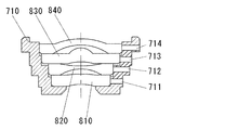
- FIG. 21 is a cross-sectional view including the optical axis of the lens in a state of being inserted into the fixing jig.
- the first lens 810, the second lens 820, the third lens 830, and the fourth lens 840 are sequentially incorporated in the fixing jig 710, and the respective lenses are superimposed as shown in FIG. Is supported by the fixing jig 710.
- Adhesive is injected from the holes 714A, 714B, and 714C to bond the first lens 810, the second lens 820, the third lens 830, and the fourth lens 840 to each other.
- a lens block in which the four lenses are integrated is completed.
- the eccentricity of a lens can be adjusted by inserting a jig bar into each through hole before bonding and moving the lens.
- the assembled lens block is fixed to the lens barrel of the camera device.
- Patent Document 2 the first through holes 711A, 711B, 711C, the second through holes 712A, 712B, 712C, the third through holes 713A, 713B, 713C shown in FIGS.
- a method of adjusting the eccentricity of the lens with respect to the lens barrel 710 by inserting a jig from a through hole such as the fourth through holes 714A, 714B, 714C is disclosed.
- the present invention solves at least one of the conventional problems as described above, and provides a lens unit capable of adjusting a lens position and the like with high accuracy by a simple method and ensuring stable performance. For the purpose.
- the lens unit according to the present invention includes at least one lens, and holds the first lens group and the second lens group having a light collecting function by arranging them in series on the same optical axis, and the first lens group.
- the adjusting mechanism includes at least one pivotally supported by the two-lens barrel in order to adjust the positional relationship in the optical axis direction and the tilt of the optical axes.
- An adjustment pin and at least one adjustment groove located on an outer surface of the first lens barrel, wherein the at least one adjustment pin has a columnar shape centering on a reference axis serving as a reference for the rotation;
- a reference shaft portion, and an eccentric portion having an eccentric shaft center that is eccentric with respect to the reference shaft center, and having at least a part of a circular cross section centered on the eccentric shaft center.
- the second lens barrel is rotatably inserted into a guide hole having an axial center in the radial direction, and the eccentric portion is engaged with the at least one adjustment groove of the first lens barrel, The small amount with respect to the reference shaft portion. Both by rotating one adjustment pin, the eccentric portion is in contact portions of the at least one adjusting groove is moved in the optical axis direction.
- the adjustment mechanism includes three each of the at least one adjustment pin and the at least one adjustment groove, and the three adjustment pins are arranged on the outer surface of the second lens barrel. They are arranged at 120 degree intervals around the axis.
- the first lens barrel moves in parallel with the optical axis direction with respect to the second lens barrel,
- the optical axis of the first lens barrel is tilted with respect to the optical axis of the second lens barrel by rotating at least one of the three adjustment pins in a direction different from the other or at a different speed.
- each adjustment pin has a barrel-shaped curved surface at least partially, and the eccentric portion is in point contact with the adjustment groove and a portion of the barrel-shaped curved surface.
- the adjustment mechanism is at least rotatably supported by the second lens barrel in order to adjust the eccentricity of the first lens barrel and the second lens barrel.
- an at least one biasing spring is provided.
- the at least one adjustment screw includes a threaded portion with a male thread, a screw head positioned at one end in the axial direction, and the axial direction.
- a pressing protrusion located at the other end, and the screw portion is screwed into a screw hole provided with a radial direction in a cross section perpendicular to the optical axis of the second lens barrel as an axial direction;
- the pressing protrusion is in contact with a screw pressing surface provided on an outer surface of the first lens barrel perpendicular to the axis of the at least one adjusting screw, and the at least one biasing spring is the first pressing spring.
- Supported by 2 lens barrel Is located in said at least one adjustment screw coaxially biases from the second lens barrel of the first lens barrel in the direction of the optical axis of the first barrel.
- the first lens barrel moves relative to the second lens barrel in a direction in which the adjustment screw advances by rotating the adjustment screw in the screw hole.
- the adjustment mechanism includes two each of the at least one adjustment screw and the at least one biasing spring, and the optical axis is in a plane perpendicular to the optical axis of the first lens barrel.
- the two adjusting screws and the two urging springs are respectively arranged on two straight lines orthogonal to each other at a point where the
- the pressing protrusion of each adjustment screw has a hemispherical surface portion, the hemispherical cross-sectional portion is in contact with the screw pressing surface, and the adjustment screw is rotated in the screw hole. By doing so, the first lens barrel moves relative to the second lens barrel in the direction in which the adjustment screw advances.
- the first lens incorporated in the first lens barrel out of lens assembly tolerances in an all-lens optical system including the first lens group and the second lens group. Between the lens closest to the second lens barrel in the group and the lens closest to the first lens barrel among the second lens group incorporated in the second lens barrel, The assembly tolerance for satisfying the required performance is the smallest as compared with the assembly tolerance of other lenses.
- the optical axis is again between the first lens barrel and the second lens barrel. Since the position of the direction, the inclination of the optical axis, and the eccentricity can be adjusted, it is possible to construct a more accurate lens unit.
- the lens unit of the present invention since the adjustment pin for adjusting the position of the first lens barrel in the optical axis direction with respect to the second lens barrel is provided, the second barrel of the first barrel with a simple configuration. It is possible to adjust the position in the optical axis direction with respect to.
- both the position of the first lens barrel in the direction parallel to the optical axis with respect to the second lens barrel and the inclination of each other are provided. Can be adjusted.
- the adjustment pin since the adjustment pin is in point contact with the adjustment groove, the first lens barrel can operate smoothly with respect to the adjustment pin.
- the adjusting screw for adjusting the position of the first lens barrel in the radial direction with respect to the second lens barrel is provided, the first barrel with respect to the second barrel can be easily configured. It is possible to adjust the eccentricity.
- two adjustment screws are provided at positions orthogonal to each other on the axis, and the position of the first lens barrel relative to the second lens barrel can be moved in two axial directions. Therefore, it is possible to move in any direction orthogonal to the optical axis.
- the adjustment screw since the adjustment screw is in contact with the pressing plane at the hemispherical surface portion on the one end face side, even when the inclination angle of the adjustment screw with respect to the first lens barrel changes, The contact state does not change greatly, and therefore the adjustment of the first lens barrel to the second lens barrel by the adjustment pin can be performed smoothly.
- the assembly error between the first lens barrel and the second lens barrel is more allowable than the assembly errors of the other lenses. Therefore, it is possible to perform high-precision adjustment only in the assembly process between the first lens barrel and the second lens barrel, and to relax the adjustment accuracy in the other lens assembly processes. . As a result, the number of adjustment steps can be reduced, and the completeness of the entire lens unit is improved.
- (A) And (b) is a front view of the lens unit of an embodiment, and a sectional view in an AA position of a figure shown in (a). It is another unit exploded perspective view of the lens unit of an embodiment.
- (A), (b), (c) is the perspective view, front view, and sectional drawing of the adjustment pin in embodiment. It is a perspective view showing the incorporation state of the adjustment pin in an embodiment.
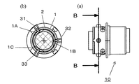
- (A) is a side view of the lens unit of the embodiment, and (b) is a cross-sectional view at the BB position in the drawing shown in (a).
- (A) is a side view of the lens unit of the embodiment, and (b) is a cross-sectional view at the BB position in the drawing shown in (a). It is an expanded sectional view near the adjustment pin of the lens unit of the embodiment. It is a perspective view of the whole lens unit of an embodiment.
- (A) is an exploded perspective view of the lens unit of the embodiment, (b) is an enlarged perspective view of the vicinity of the notch portion of the first lens barrel. It is a perspective view showing the incorporation state of the 2nd adjustment screw in an embodiment.
- (A) is a side view of the lens unit of the embodiment, and (b) is a cross-sectional view at the BB position in the drawing shown in (a).
- (A), (b), (c) is the perspective view of the other form of the adjustment pin in embodiment, a front view, and sectional drawing in the AA position of the figure shown to (b).
- (A), (b) is a side view of an embodiment of a lens unit using the adjustment pin shown in FIG. 16, and a cross-sectional view at the FF position of the drawing shown in (a).
- (A), (b), (c) is the perspective view of the other form of the adjustment pin in embodiment, a front view, and sectional drawing in the AA position of the figure shown to (b).
- (A), (b), (c) is the perspective view of the embodiment of the lens unit using the adjustment pin shown in FIG. 17, a side view, and a sectional view at the FF position of the drawing shown in (b). It is a disassembled perspective view which shows the state by which the lens was assembled to the lens barrel in the conventional lens unit. It is sectional drawing which shows the state by which the lens was assembled to the lens barrel in the conventional lens unit.
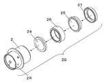
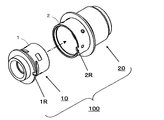
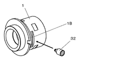
- the lens unit 100 includes a first unit 10 and a second unit 20.
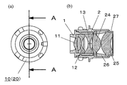
- the first unit 10 includes a first lens barrel 1 and a first lens group inserted into the first lens barrel 1, that is, a first lens 11, a second lens 12, and a first lens barrel 1. 3 lenses 13.
- the second unit 20 includes a second lens barrel 2, a second lens group inserted into the second lens barrel 2, that is, a fourth lens 24 and a fifth lens 25, A spacer 26 and a lens holder 27 are included.
- the spacer 26 defines the distance between the fourth lens 24 and the fifth lens 25.
- the lens retainer 27 prevents the fourth lens 24 and the fifth lens 25 from coming off the second lens barrel 2.
- the second lens barrel 2 has an inner surface that encloses at least a part of the first lens barrel 1.
- the first lens group and the second lens group are arranged in series on the same optical axis, thereby exhibiting a predetermined light collecting function required for the lens unit 100.
- the first unit 10 is inserted into the second lens barrel 2 of the second unit 20 with each lens inserted.
- the first lens barrel 1 is provided with a positioning guide notch 1R
- the second lens barrel is provided with a positioning guide protrusion 2R.
- the positioning guide notches 1R and the positioning guide protrusions 2R are fitted to each other, and the angular positions of the lens barrels in the rotational direction are uniquely positioned.
- 5A and 5B are a front view and a cross-sectional view of the lens unit 100 incorporated in this manner.
- the reason why the first unit 10 and the second unit 20 are divided will be described.
- a lens unit without a zoom drive or focus drive mechanism when a lens is incorporated into the lens unit, all lenses are sequentially incorporated into a single lens barrel.
- each lens and the lens barrel are allowed to shift with respect to the lens barrel within the range of accuracy variations in the finished dimensions.
- the deviation of each lens and the lens barrel is not allowed to be displaced with respect to the lens barrel even within the range of accuracy variations in the dimensions of the finished shape of each lens and the lens barrel, it is necessary to finely adjust the deviation amount. is there.
- the optical axis of the already inserted lens and the optical axis of the inserted lens are measured while measuring the reflection decentering of the lens, MTF (Modulation Transfer Function), etc.
- the position of the lens is adjusted so that.
- the optical axes of the lenses cannot be matched with sufficiently high accuracy by such a method.
- the above method is followed, or the required accuracy is further reduced, and only a part of the lenses is intensively adjusted specially. That is, in the lens unit, adjustment is performed by dividing a lens that performs high-precision adjustment intensively from other lenses.
- the lens unit includes, for example, five lenses.
- the optical system is preferably configured so that if the optical axis between the third lens 13 and the fourth lens 24 is adjusted with high accuracy, high-precision performance can be obtained as the lens optical system of the entire lens unit. Is designed. In other words, out of the lens assembly tolerance of the entire lens unit, the lens closest to the second lens barrel 2 and the second lens barrel in the first lens group incorporated in the first lens barrel 1.
- the assembly tolerance for satisfying the required performance with the lens closest to the first lens barrel 1 in the second lens group incorporated in 2 is the largest compared to the assembly tolerance of the other lenses. small.
- the optical system of the lens unit includes a first unit 10 incorporating the first lens 11, the second lens 12, and the third lens 13, and a second unit 20 incorporating the fourth lens 24 and the fifth lens 25.
- the optical axis shift and inclination of the third lens 13 and the fourth lens 24 and the distance between the lenses are adjusted with high accuracy.
- the first unit 10 includes three lenses, and the second unit includes two lenses, but each of the first unit 10 and the second unit 20 includes at least one lens. Good.
- the first lens unit can adjust the optical axes of two adjacent lenses that most greatly affect the optical performance of the optical system of the lens unit among the plurality of lenses constituting the lens unit. It is preferable to arrange a plurality of lenses in the unit 10 and the second unit 20.
- the lens unit includes seven lenses, and the optical axis misalignment of the third and fourth lenses affects the overall performance of the lens unit optical system more than the optical axis misalignment between other lenses.
- the first unit 10 is preferably provided with the first to third lenses
- the second unit 20 is preferably provided with the fourth to seventh lenses.
- the optical performance of the entire lens unit is the highest by a simple method.
- the position of the lens can be adjusted as follows.
- the present invention is not limited to the case where the lens assembly tolerance between the two adjacent lenses of the first lens group and the second lens group is the smallest.
- the two adjacent lenses having the smallest lens assembly tolerance may be positioned so as to sandwich the spacer 26, and the spacer 26 may be designed so that the alignment error is within the lens assembly tolerance.
- the alignment error is not limited to the spacer 26 and may be designed by other means provided in the lens unit so that the alignment error is within the lens assembly tolerance. In this case, even if the lens assembly tolerance of two adjacent lenses of the first lens group and the second lens group is designed to be the second smallest value, the optical performance of the entire lens unit is maximized. The lens position can be adjusted.
- the lens unit is not provided with any other positioning means and the lens assembly tolerance between two adjacent lenses of the first lens group and the second lens group is not the smallest, at least the first lens group And the second lens group can be easily aligned and the inclination of the optical axis can be easily adjusted. Therefore, it is easier to assemble the lens than in the past.
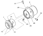
- the lens unit includes a first adjustment pin 31, a second adjustment pin 32, and a third adjustment pin 33 as an adjustment mechanism.
- the first lens barrel 1 includes a first adjustment groove 1A, a second adjustment groove 1B, and a third adjustment groove 1C.
- the first adjustment pin 31, the second adjustment pin 32, and the third adjustment pin 33 rotate to the first guide hole 2A, the second guide hole 2B, and the third guide hole 2C provided in the second lens barrel 2, respectively. It is inserted into the first adjustment groove 1A, the second adjustment groove 1B, and the third adjustment groove 1C of the first lens barrel 1 while being supported (axially supported).
- adjustment pins when the first adjustment pin 31, the second adjustment pin 32, and the third adjustment pin 33 are collectively referred to, they may be simply referred to as adjustment pins.
- the adjustment pins are provided at three locations. If the three locations are determined, the posture of the first unit 10 is uniquely determined. If there are two places, the degree of freedom remains, and if there are four places, it becomes over-constrained. From the above, three locations are optimal. However, it is possible to adjust the inclination of the optical axes of the first lens barrel and the second lens barrel and to adjust the positions in the optical axis direction even at one place, two places, or five places or more. It is preferable that three adjustment pins are provided on the outer surface of the second lens barrel 2 at intervals of 120 degrees with the optical axis of the second lens barrel 2 as the center.
- FIG. 7A, 7B, and 7C are a perspective view, a front view, and a sectional view showing the shapes of the first adjustment pin 31, the second adjustment pin 32, and the third adjustment pin 33, respectively.
- Each of the first adjustment pin 31, the second adjustment pin 32, and the third adjustment pin 33 has a reference shaft portion 3A, an eccentric portion 3B, and an operation portion 3C. These have, for example, a substantially cylindrical shape. is doing.
- the cross section perpendicular to the direction in which the cylindrical shape extends is the largest in the operation portion 3C, and the cross-sectional area decreases in the order of the reference shaft portion 3A and the eccentric portion 3B. For this reason, a step is generated at the boundary between adjacent portions.
- the eccentric shaft center of the eccentric portion 3B is eccentric by the eccentric dimension G3AB with respect to the reference shaft center of the reference shaft portion 3A.
- the operation portion 3C is positioned coaxially with respect to the reference shaft portion 3A.
- each adjustment pin has a barrel-shaped curved surface, and the cross-sectional shape is a curved cross section as shown in FIG.
- the first adjustment pin 31, the second adjustment pin 32, and the third adjustment pin 33, and the bottoms of the first adjustment groove 1A, the second adjustment groove 1B, and the third adjustment groove 1C are connected to the tip 3D. Point contact.
- FIG. 8 shows in detail the position where the second adjustment pin 32 is inserted into the second adjustment groove 1B.
- 9A and 9B are a side view showing a state in which the first adjustment pin 31, the second adjustment pin 32, and the third adjustment pin 33 are incorporated, and a cross section in a direction orthogonal to the optical axis direction.
- FIGS. 10A and 10B are a side view and a cross-sectional view in a direction parallel to the axial direction.
- FIG. 11 is an enlarged view showing the vicinity of the second adjustment pin 32 in FIG. 10 in detail.
- the first adjustment groove 1 ⁇ / b> A, the second adjustment groove 1 ⁇ / b> B, and the third adjustment groove 1 ⁇ / b> C each extend in the circumferential direction, and the first lens It is provided on a part of the outer surface of the lens barrel 1.
- the adjustment groove width can be inserted into the tip 3D provided on the second adjustment pin 32, and the backlash of both is minimal, that is, the inner surface of the second adjustment groove 1B.
- the gap with the tip 3D is preferably as small as possible.
- the first adjustment pin 31 and the third adjustment pin 33 have the same configuration according to this.
- the operation of such a structure will be described with reference to FIG.
- the inclination (angle) between the optical axis a10 of the first unit 10 (and the first lens barrel) and the optical axis a20 of the second unit 20 (and the second lens barrel) is determined by the first adjustment pin 31 and the second adjustment.
- the first adjustment groove 1A, the second adjustment groove 1B, and the third adjustment groove 1C are uniquely determined by the pins 32 and the third adjustment pins 33.
- the first adjustment pin 31, the second adjustment pin 32, and the third adjustment pin 33 are individually rotated in one direction in the directions of the arrow D31R, the arrow D32R, and the arrow D33R, respectively.
- the first adjustment groove 1A moves in the direction of arrow D31L
- the second adjustment groove 1B moves in the direction of arrow D32L
- the third adjustment groove 1C moves in the direction of arrow D33L.
- the first unit 10 is inclined in the directions of arrows D31T, D32T, and D33T, respectively.
- the adjustment amount it is possible to set to any angle by appropriately allocating the adjustment amount, rather than operating each adjustment pin alone. For example, by rotating all of the first adjustment pin 31, the second adjustment pin 32, and the third adjustment pin 33 simultaneously in the same direction at the same speed, the first lens barrel 1 with respect to the second lens barrel 2. Moves parallel to the optical axis direction. Further, by rotating at least one of the three adjustment pins in a direction different from the other or at a different speed, the light of the first lens barrel 1 with respect to the optical axis a ⁇ b> 20 of the second lens barrel 2. The axis a10 is inclined.
- the tip 3D of each adjustment pin has a curved cross section, so that it can be smoothly adjusted without any trouble by being in point contact.
- the end surface of the positioning guide notch 1R provided in the first lens barrel 1 preferably has a curved shape.
- the difference between the positions of the first unit 10 and the second unit 20 in the axial direction in the adjustment portion of each adjustment pin does not change.
- the axial angle between the first unit 10 and the second unit 20 changes without changing the inclination angle formed by the optical axis a10 and the optical axis a20 of the second unit 20. Using this principle, the axial position of the first unit 10 relative to the second unit 20 can be adjusted.
- the first adjustment groove 1A, the second adjustment groove 1B, and the third adjustment groove 1C are separated from each other as shown in FIG. 9, but are all continuous in the circumferential direction, for example. Needless to say, even a circumferential adjustment groove performs the same function.
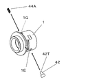
- the lens unit is a first adjusting screw 41 and a second adjusting screw 42, and a first force that applies a reaction force to the first adjusting screw 41 and the second adjusting screw 42 as an adjusting mechanism.
- a first biasing spring 43A and a second biasing spring 44A are provided.
- the present embodiment further includes a first spring presser 43B and a second spring presser 44B that hold the first biasing spring 43A and the second biasing spring 44A.
- Each of the first adjustment screw 41 and the second adjustment screw 42 includes a threaded portion, a screw head provided at one end in the axial direction, and a pressing protrusion provided at the other end.
- the screw portions of the first adjustment screw 41 and the second adjustment screw 42 are in contact with the first screw holding surface 1D and the second screw holding surface 1E provided on the first lens barrel 1.
- the first adjustment screw hole 2D and the second adjustment screw hole 2E provided in the second lens barrel 2 are attached.
- the first spring retainer 43B and the second spring retainer 44B are provided with the first adjustment spring 43 and the second adjustment spring 44, the first spring biasing surface 1F provided on the first lens barrel 1, and the second spring attachment. With the urging surface 1G urged, it is fastened and fixed to the first spring fixing hole 2F and the second spring fixing hole 2G provided in the second lens barrel 2 with screws or the like.
- the first adjustment spring 43A and the first adjustment spring retainer 43B, the second adjustment spring 44A and the second adjustment spring retainer 44B are on the axes of the first adjustment screw 41 and the second adjustment screw 42, respectively, and the second lens. It is provided at a position facing the first adjustment screw 41 and the second adjustment screw 42 with respect to the optical axis of the lens barrel 2.
- the first adjustment screw 41, the first adjustment spring 43A, and the first adjustment spring are arranged on two straight lines perpendicular to the optical axis a10 of the first lens barrel 1 at the point where the optical axis a10 is located.
- the presser 43B, the second adjustment screw 42, the second adjustment spring 44A, and the second adjustment spring presser 44B are respectively disposed.
- FIG. 13 the relationship between the first adjustment screw 41 and the second adjustment screw 42 with respect to the first screw holding surface 1D and the second screw holding surface 1E, and further, the first spring biasing surface 1F and the second spring attached.
- the first lens barrel 1 is shown in a state of being detached from the second lens barrel.
- the lens barrel 1 is brought into contact with or urged according to each connecting line shown in FIG.
- FIG. 14 is a diagram for explaining a state in which the second adjustment screw 42 is in contact with the second screw holding surface 1E and a state in which the second adjustment spring 44 biases the second spring biasing surface 1G.
- 15 shows a state in which the first adjustment screw 41 and the second adjustment screw 42, the first adjustment spring 43A, the first spring presser 43B, the second biasing spring 44A, and the second spring presser 44B are incorporated. It is the figure represented with the cross section of the direction orthogonal to an axial direction.
- the first screw pressing surface 1 ⁇ / b> D, the second screw pressing surface 1 ⁇ / b> E, the first spring biasing surface 1 ⁇ / b> F, and the second spring biasing surface 1 ⁇ / b> G are formed on the first lens barrel 1. It is provided on a part of the outer surface. These surfaces are orthogonal to the axial directions of the first adjustment screw 41, the second adjustment screw 42, the first urging spring 43A, and the second urging spring 44A, respectively. As a result, the force of each adjusting screw and the biasing spring can be appropriately applied to the first lens barrel 1.
- the second adjustment screw 42 is adjusted by appropriately rotating in the direction of arrow D42R.
- the first adjustment screw 41, the second adjustment screw 42, the first urging spring 43A, and the second urging spring 44A are respectively in the direction of the arrow D41J, the arrow D42J, the arrow D43J, and
- the spring specifications are such that a force is always applied in the direction of arrow D44J. In this way, the first unit 10 can follow the movement caused by the rotation of the first adjustment screw 41 and the second adjustment screw 42.
- first adjustment screw 41 and the second adjustment screw 42 are provided orthogonal to each other, and the first screw holding surface 1D and the second screw holding surface 1E are orthogonal to each other. Adjustment using the first adjustment screw 41 and the second adjustment screw 42 functions independently, and position adjustment in the A1 direction and position adjustment in the A2 direction in FIG. 15 can be performed independently.
- the pressing protrusion 41T and the pressing protrusion 42T of the first adjustment screw 41 and the second adjustment screw 42 have a hemispherical shape, and the contact between the first screw holding surface 1D and the second screw holding surface 1E is pointed. In contact.
- the first adjustment pin 41, the first screw holding surface 1D, the second adjustment screw 42, and the second adjustment screw 33 are adjusted by the first adjustment pin 31, the second adjustment pin 32, and the third adjustment pin 33 as described above. Even if the contact angle with the two-screw holding surface 1E changes, it is possible to smoothly change the angle of the first lens barrel 1 with respect to the second lens barrel 2.
- the first adjustment pin 31, the second adjustment pin 32, the third adjustment pin 33, the first adjustment screw 41, and the second adjustment screw 42 are prevented from rotating.
- the adjustment screw and the second lens barrel 2 may be fixed with an adhesive or the like.
- FIGS. 16A, 16 ⁇ / b> B, and 16 ⁇ / b> C are perspective views of a first adjustment pin 31 ′, a second adjustment pin 32 ′, and a third adjustment pin 33 ′ having shapes different from those in the above embodiment. The front view and sectional drawing are shown.
- Each of the first adjustment pin 31 ', the second adjustment pin 32', and the third adjustment pin 33 ' has a reference shaft portion 3A, an eccentric portion 3B', and an operation portion 3C.
- the eccentric part 3B ' has an axis that is inclined with respect to the reference axis of the reference axis part 3A. Therefore, the tip 3D of the eccentric portion 3B 'has an eccentric shaft that is eccentric with respect to the reference axis.
- FIGS. 17A and 17B are a side view and a cross-sectional view of a lens unit 100 ′ using the first adjustment pin 31 ′, the second adjustment pin 32 ′, and the third adjustment pin 33 ′. Similar to the above embodiment, the first adjustment pin 31 ′, the second adjustment pin 32 ′, and the third adjustment pin 33 ′ are provided in the second lens barrel 2 with the first guide hole 2 A, the second guide hole 2 B, and the second adjustment pin 31 ′. 3 is rotatably supported in the guide hole 2C.
- the eccentric portion 3B ′ and the tip portion 3D of the first adjustment pin 31 ′, the second adjustment pin 32 ′, and the third adjustment pin 33 ′ are the first adjustment groove 1A, the second adjustment groove 1B, and the third adjustment, respectively. It is inserted into the groove 1C.
- the first adjustment pin 31 ′, the second adjustment pin 32 ′, and the third adjustment pin 33 ′ having such a structure are the first adjustment pin 31, the second adjustment pin 32, and the third adjustment pin described in the above embodiment.
- the lens unit 100 functions in the same manner as the first adjustment pin 31, the second adjustment pin 32, and the third adjustment pin 33 in the lens unit 100 of the above embodiment.
- FIGS. 18A, 18B, and 18C show the first adjustment pin 31 ′′, the second adjustment pin 32 ′′, and the third adjustment pin 33 ′′ having shapes different from those of the above embodiment.
- a perspective view, a front view, and a cross-sectional view are shown.
- each of the first adjustment pin 31 ′′, the second adjustment pin 32 ′′, and the third adjustment pin 33 ′′ has a reference shaft portion 3A, an operation portion 3C, and a tip portion 3E.
- the tip portion 3E has a conical side surface whose cross section decreases from the reference shaft portion 3A toward the tip.
- the axis of the tip 3E coincides with the reference axis of the reference shaft 3A and is not eccentric.
- a male screw is provided on the side surface of the reference shaft portion 3A.
- FIGS. 19A, 19B, and 19C are perspective views of a lens unit 100 ′′ using the first adjustment pin 31 ′′, the second adjustment pin 32 ′′, and the third adjustment pin 33 ′′. It is a side view and sectional drawing.
- the lens unit 100 ′′ uses the first lens unit 10 as the adjustment mechanism as the second lens unit 20 side. It is preferable to further include a spring 51 having both ends connected to the first lens unit 10 and the second lens unit 20 in order to urge the lens.
- a first guide hole 2A and a second guide hole provided in the second lens barrel 2 for supporting the first adjustment pin 31 ′′, the second adjustment pin 32 ′′, and the third adjustment pin 33 ′′. It is preferable that a female screw is formed in 2B and the third guide hole 2C (FIG. 6).
- the tip 3D of the first adjustment pin 31 ′′, the second adjustment pin 32 ′′, and the third adjustment pin 33 ′′ are formed in the first adjustment groove 1A and the second adjustment groove 1B.
- the conical side surface of the tip 3D is inserted into the third adjustment groove 1C, and is in contact with the side walls of these adjustment grooves.
- the tip 3D As a result, the first adjustment pin 31 ′′, the second adjustment pin 32 ′′, and the third adjustment pin are changed as described in the above embodiment with reference to FIG.
- the first adjustment groove 1A is in the direction of arrow D31L
- the twenty-first adjustment groove 1B is in the direction of arrow D32L
- the third Each adjustment groove 1C moves independently in the direction of arrow D33L.
- the first unit 10 is inclined in the directions of arrows D31T, D32T, and D33T, respectively.
- the lenses incorporated in the first unit 10 and the second lens barrel 2 are three and two, respectively.
- the effects of the present invention can be obtained without being limited to this. Yes.
- the same effect can be obtained regardless of whether the material constituting the lens is resin or glass.
- the lens barrel is made of metal, and if the lens is made of resin, the lens barrel is made of resin. This is preferable in terms of reducing distortion due to the difference in deformation.
- the shape of the optically effective surface is not limited to the shape shown in each drawing, and the effects of the present invention can be obtained.
- the present invention has been described by taking a lens unit with a fixed magnification as an example, but the present invention can also be suitably used for a lens unit having a zoom function.
- the adjustment mechanism of the lens unit includes the adjustment pin that adjusts the positional relationship between the first lens barrel and the second lens barrel in the optical axis direction and the inclination of the optical axis, and the eccentricity between each other. With adjusting screws to adjust.
- An adjusting mechanism for adjusting at least one of the eccentricity may be provided.
- a screw is provided on an adjustment pin for adjusting the positional relationship between the first lens barrel and the second lens barrel in the optical axis direction and the inclination of the optical axis, and the tip of the adjustment pin is the bottom of the adjustment groove.
- the adjustment pins may also have a function of adjusting the eccentricity of the optical axes of each other by abutting with each other.
- the lens unit according to the present invention is useful in a case where high accuracy is required for each error in the position in the optical axis direction, tilt, or eccentricity of a lens that is used in a camera or the like and is incorporated in a lens barrel.
Abstract
Description
1A 第1調整溝
1B 第2調整溝
1C 第3調整溝
1D 第1ネジ押さえ面
1E 第2ネジ押さえ面
1F 第1バネ付勢面
1G 第2バネ付勢面
1R 位置決めガイド切欠
10 第1鏡筒
11 第1レンズ
12 第2レンズ
13 第3レンズ
2 第2レンズ鏡筒
2A 第1ガイド穴
2B 第2ガイド穴
2C 第3ガイド穴
2D 第1調整ネジ穴
2E 第2調整ネジ穴
2F 第1バネ固定穴
2G 第2バネ固定穴
2R 位置決め突起
20 第2鏡筒
24 第4レンズ
25 第5レンズ
26 スペーサ
27 レンズ押さえ
31 第1調整ピン
32 第2調整ピン
33 第3調整ピン
3A 基準軸部
3B 偏心部
3C 操作部
41 第1調整ネジ
41T 押圧突起部
42 第2調整ネジ
42T 押圧突起部
43A 第1付勢バネ
43B 第1バネ押さえ
44A 第2付勢バネ
44B 第2バネ押さえ DESCRIPTION OF
Claims (10)
- それぞれ少なくとも一枚のレンズを含み、同じ光軸上で直列に配置することにより集光機能を有する第1レンズ群および第2レンズ群と、
前記第1レンズ群を保持する第1レンズ鏡筒と、
前記第2レンズ群を保持し、かつ前記第1レンズ鏡筒の少なくとも一部を内包する、第2レンズ鏡筒と、
前記第1レンズ鏡筒および前記第2レンズ鏡筒のうち、前記第2レンズ鏡筒が前記第1レンズ鏡筒の少なくとも一部を内包している領域に設けられており、前記第1レンズ鏡筒と前記第2レンズ鏡筒との、互いの光軸方向の位置関係、互いの光軸の傾き、および互いの偏心の少なくとも1つを調整するための調整機構と
を備えるレンズユニット。 A first lens group and a second lens group each including at least one lens and having a light collecting function by being arranged in series on the same optical axis;
A first lens barrel holding the first lens group;
A second lens barrel that holds the second lens group and encloses at least a portion of the first lens barrel;
Of the first lens barrel and the second lens barrel, the second lens barrel is provided in a region including at least a part of the first lens barrel, and the first lens mirror A lens unit comprising: an adjustment mechanism for adjusting at least one of a positional relationship between the cylinder and the second lens barrel in the optical axis direction, an inclination of the optical axis, and an eccentricity of each other. - 前記調整機構は、前記互いの光軸方向の位置関係および前記互いの光軸の傾きを調整するために、前記2レンズ鏡筒に回動可能に支持された少なくとも1つの調整ピン、および、前記第1レンズ鏡筒の外側面に位置する少なくとも1つの調整溝を含み、
前記少なくとも1つの調整ピンは、前記回動の基準となる基準軸心を中心とした円柱状の基準軸部と、前記基準軸心に対して偏心した偏心軸心を有し、前記偏心軸心を中心とした円形断面を少なくとも一部に有する偏心部とを含み、
前記基準軸部は、前記第2レンズ鏡筒の半径方向に軸心が設けられたガイド穴に回動可能に挿入され、
前記偏心部は、前記第1レンズ鏡筒の前記少なくとも1つの調整溝に係合しており、
前記基準軸部を基準にして前記少なくとも1つの調整ピンを回動させることにより、前記少なくとも1つの調整溝の前記偏心部が接する部分が光軸方向に移動する、請求項1に記載のレンズユニット。 The adjustment mechanism includes at least one adjustment pin rotatably supported by the two-lens barrel in order to adjust the positional relationship in the optical axis direction and the inclination of the optical axes. Including at least one adjustment groove located on the outer surface of the first lens barrel;
The at least one adjustment pin has a columnar reference shaft centered on a reference axis serving as a reference for the rotation, and an eccentric shaft center that is eccentric with respect to the reference axis, and the eccentric shaft center. An eccentric portion having at least a part of a circular cross section centered on
The reference shaft portion is rotatably inserted into a guide hole provided with an axial center in the radial direction of the second lens barrel.
The eccentric portion is engaged with the at least one adjustment groove of the first lens barrel,
2. The lens unit according to claim 1, wherein a portion of the at least one adjustment groove that is in contact with the eccentric portion moves in the optical axis direction by rotating the at least one adjustment pin with respect to the reference shaft portion. . - 前記調整機構は、前記少なくとも1つの調整ピンおよび前記少なくとも1つの調整溝をそれぞれ3つ含み、
前記3つの調整ピンは、前記第2レンズ鏡筒の外側面において、前記光軸を中心として120度間隔で配置されている請求項2に記載のレンズユニット。 The adjustment mechanism includes three each of the at least one adjustment pin and the at least one adjustment groove,
3. The lens unit according to claim 2, wherein the three adjustment pins are arranged at intervals of 120 degrees with the optical axis as a center on the outer surface of the second lens barrel. - 前記3つの調整ピンを同時に同方向へ同速度で回動させることにより、前記第2レンズ鏡筒に対して第1レンズ鏡筒が光軸方向と平行に移動し、
前記3つの調整ピンの少なくとも1つを他と異なる方向にまたは異なる速度で回動させることにより、前記第2レンズ鏡筒の前記光軸に対して、前記第1レンズ鏡筒の前記光軸が傾く、請求項3に記載のレンズユニット。 By simultaneously rotating the three adjustment pins in the same direction at the same speed, the first lens barrel moves in parallel with the optical axis direction with respect to the second lens barrel,
By rotating at least one of the three adjustment pins in a direction different from the other or at a different speed, the optical axis of the first lens barrel is shifted with respect to the optical axis of the second lens barrel. The lens unit according to claim 3, wherein the lens unit is inclined. - 各調整ピンの前記偏心部は、少なくとも一部に樽状曲面を有し、前記偏心部は前記調整溝と前記樽状曲面の一部で点接触する、請求項3に記載のレンズユニット。 4. The lens unit according to claim 3, wherein the eccentric portion of each adjustment pin has a barrel-shaped curved surface at least partially, and the eccentric portion is in point contact with the adjustment groove and a portion of the barrel-shaped curved surface.
- 前記調整機構は、前記第1レンズ鏡筒と前記第2レンズ鏡筒との互いの偏心を調整するために、前記第2レンズ鏡筒に回動可能に支持された少なくとも1つの調整ネジ、および、少なくとも1つの付勢バネをさらに含み、
前記少なくとも1つの調整ネジは、雄ネジが施されたネジ部と、軸方向の一端に位置するネジ頭部および前記軸方向の他端に位置する押圧突起部を有し、
前記ネジ部は、前記第2レンズ鏡筒の前記光軸に垂直な断面における半径方向を軸方向として設けられたネジ穴にねじこまれており、
前記押圧突起部は、前記少なくとも1つの調整ネジの軸心に直交して前記第1レンズ鏡筒の外側面に設けられたネジ押さえ面に当接し、
前記少なくとも1つの付勢バネは、前記第2レンズ鏡筒に支持された前記少なくとも1つの調整ネジと同軸上に位置し、前記第2レンズ鏡筒から前記第1レンズ鏡筒を前記第1鏡筒の光軸の方向へ付勢する、請求項1または5に記載のレンズユニット。 The adjusting mechanism includes at least one adjusting screw rotatably supported by the second lens barrel in order to adjust the eccentricity of the first lens barrel and the second lens barrel; Further comprising at least one biasing spring;
The at least one adjustment screw has a threaded portion provided with a male thread, a screw head positioned at one end in the axial direction, and a pressing protrusion positioned at the other end in the axial direction,
The screw part is screwed into a screw hole provided with a radial direction in a cross section perpendicular to the optical axis of the second lens barrel as an axial direction,
The pressing protrusion is in contact with a screw pressing surface provided on an outer surface of the first lens barrel perpendicular to the axis of the at least one adjustment screw,
The at least one biasing spring is positioned coaxially with the at least one adjustment screw supported by the second lens barrel, and the first lens barrel is moved from the second lens barrel to the first mirror. The lens unit according to claim 1, wherein the lens unit is biased in the direction of the optical axis of the tube. - 前記ネジ穴にて前記調整ネジを回動させることにより、前記調整ネジが進む方向に、前記第1レンズ鏡筒が前記第2レンズ鏡筒に対して移動する、請求項6に記載のレンズユニット。 The lens unit according to claim 6, wherein the first lens barrel moves with respect to the second lens barrel in a direction in which the adjustment screw advances by rotating the adjustment screw in the screw hole. .
- 前記調整機構は、前記少なくとも1つの調整ネジおよび前記少なくとも1つの付勢バネをそれぞれ2つ含み、
前記第1レンズ鏡筒の前記光軸と垂直な平面の、前記光軸の位置する点で直交する2つの直線上において、前記2つの調整ネジおよび前記2つの付勢バネがそれぞれ配置されている請求項7に記載のレンズユニット。 The adjustment mechanism includes two each of the at least one adjustment screw and the at least one biasing spring,
The two adjusting screws and the two urging springs are respectively arranged on two straight lines perpendicular to the optical axis of the first lens barrel on the point where the optical axis is located. The lens unit according to claim 7. - 各調整ネジの前記押圧突起部は、半球状面部を有し、前記半球状断面部が前記ネジ押さえ面に当接しており、
前記ネジ穴にて前記調整ネジを回動させることにより、前記調整ネジが進む方向に、前記第1レンズ鏡筒が前記第2レンズ鏡筒に対して移動する、請求項8に記載のレンズユニット。 The pressing protrusion of each adjustment screw has a hemispherical surface portion, and the hemispherical cross-sectional portion is in contact with the screw pressing surface,
The lens unit according to claim 8, wherein the first lens barrel moves relative to the second lens barrel in a direction in which the adjustment screw advances by rotating the adjustment screw in the screw hole. . - 前記第1のレンズ群と、前記第2のレンズ群とを併せた全レンズ光学系におけるレンズ組立許容誤差のうち、
前記第1レンズ鏡筒に組み込まれた前記第1レンズ群のうちの、第2レンズ鏡筒と最も近接するレンズと、前記第2のレンズ鏡筒に組み込まれた第2レンズ群のうち前記第1レンズ鏡筒に最も近接するレンズとの間の、要求性能を満たすための組立許容誤差が、他のレンズ同士の組立許容誤差に比べ最も小さい、請求項1から9のいずれかに記載のレンズユニット。 Among lens assembly tolerances in an all-lens optical system that combines the first lens group and the second lens group,
Of the first lens group incorporated in the first lens barrel, the lens closest to the second lens barrel and the second lens group incorporated in the second lens barrel. The lens according to any one of claims 1 to 9, wherein an assembly tolerance for satisfying a required performance with a lens closest to one lens barrel is the smallest as compared with an assembly tolerance between other lenses. unit.
Priority Applications (4)
| Application Number | Priority Date | Filing Date | Title |
|---|---|---|---|
| US13/807,951 US8917463B2 (en) | 2010-07-07 | 2011-07-06 | Lens unit |
| EP11803332.3A EP2592457B1 (en) | 2010-07-07 | 2011-07-06 | Lens unit |
| JP2012523768A JP5779179B2 (en) | 2010-07-07 | 2011-07-06 | Lens unit |
| CN201180031990.XA CN102959447B (en) | 2010-07-07 | 2011-07-06 | Lens unit |
Applications Claiming Priority (2)
| Application Number | Priority Date | Filing Date | Title |
|---|---|---|---|
| JP2010-154522 | 2010-07-07 | ||
| JP2010154522 | 2010-07-07 |
Publications (1)
| Publication Number | Publication Date |
|---|---|
| WO2012004995A1 true WO2012004995A1 (en) | 2012-01-12 |
Family
ID=45440984
Family Applications (1)
| Application Number | Title | Priority Date | Filing Date |
|---|---|---|---|
| PCT/JP2011/003879 WO2012004995A1 (en) | 2010-07-07 | 2011-07-06 | Lens unit |
Country Status (5)
| Country | Link |
|---|---|
| US (1) | US8917463B2 (en) |
| EP (1) | EP2592457B1 (en) |
| JP (1) | JP5779179B2 (en) |
| CN (1) | CN102959447B (en) |
| WO (1) | WO2012004995A1 (en) |
Cited By (9)
| Publication number | Priority date | Publication date | Assignee | Title |
|---|---|---|---|---|
| CN102798956A (en) * | 2012-08-08 | 2012-11-28 | 中国科学院上海光学精密机械研究所 | Picture frame structure of heavy-calibre combined lens |
| EP2703885A1 (en) * | 2012-04-13 | 2014-03-05 | Raytheon Company | Positioning mechanism for aligning an optical device and an image sensor |
| JP2014081430A (en) * | 2012-10-15 | 2014-05-08 | Nikon Corp | Imaging lens, optical device and imaging lens adjustment method |
| CN104106002A (en) * | 2012-11-16 | 2014-10-15 | 松下电器(美国)知识产权公司 | Camera drive device |
| KR20150102683A (en) * | 2014-02-28 | 2015-09-07 | 삼성전자주식회사 | Lens Barrel, Image Sensor Support Structure, Electronic View Finder and Image Capture Apparatus |
| JP2018097095A (en) * | 2016-12-11 | 2018-06-21 | 日本電産コパル株式会社 | Pin and imaging device |
| US10694088B2 (en) | 2017-08-08 | 2020-06-23 | Canon Kabushiki Kaisha | Lens apparatus, imaging apparatus, and manufacturing method of the lens apparatus |
| JP2020531923A (en) * | 2017-09-11 | 2020-11-05 | ▲寧▼波舜宇光▲電▼信息有限公司 | Imaging module and its assembly method |
| CN114355543A (en) * | 2021-12-09 | 2022-04-15 | 德伽智能光电(镇江)有限公司 | Off-axis lens system |
Families Citing this family (15)
| Publication number | Priority date | Publication date | Assignee | Title |
|---|---|---|---|---|
| CN105739048A (en) * | 2014-12-12 | 2016-07-06 | 信泰光学(深圳)有限公司 | Coaxial focusing lens group adjusting mechanism |
| CN105445888B (en) | 2015-12-21 | 2020-04-03 | 宁波舜宇光电信息有限公司 | Adjustable optical lens, camera module and calibration method thereof |
| EP4180852A1 (en) * | 2015-10-30 | 2023-05-17 | Ningbo Sunny Opotech Co., Ltd. | Adjustable optical lens and camera module and manufacturing method and applications thereof |
| KR102094627B1 (en) * | 2015-12-16 | 2020-03-27 | 닝보 써니 오포테크 코., 엘티디. | Lens assembly with integrated focusing device, camera module and assembly method thereof |
| CN107290836B (en) * | 2016-03-30 | 2020-04-10 | 上海微电子装备(集团)股份有限公司 | Lens adjusting device and adjusting method |
| JP6731280B2 (en) | 2016-05-06 | 2020-07-29 | 日本電産コパル株式会社 | Imaging device |
| JP6816398B2 (en) * | 2016-08-03 | 2021-01-20 | リコーイメージング株式会社 | Lens barrel and imaging device |
| JP6952581B2 (en) * | 2017-11-10 | 2021-10-20 | 株式会社ミツトヨ | Tilt adjustment mechanism |
| CN108169918B (en) * | 2017-12-28 | 2023-04-11 | 中国科学院西安光学精密机械研究所 | Underwater imaging laser illumination light spot homogenization adjusting device |
| CN111090159B (en) * | 2018-10-24 | 2021-10-29 | 宁波舜宇光电信息有限公司 | Optical lens, camera module, assembling method of camera module and corresponding terminal equipment |
| JP7259316B2 (en) | 2018-12-19 | 2023-04-18 | 株式会社デンソー | Lens module and imaging device for vehicle |
| CN109471234B (en) * | 2019-01-04 | 2024-01-26 | 长春博信光电子有限公司 | Jig for cementing lens and positioning cementing method |
| CN110908058B (en) * | 2019-10-31 | 2023-04-07 | 中国航空工业集团公司洛阳电光设备研究所 | Multi freedom optical axis timing device |
| CN111474734B (en) * | 2020-04-13 | 2022-11-22 | 宁波大学 | Wide-range high-frequency-response optical confocal measuring head |
| CN115220168A (en) * | 2022-06-06 | 2022-10-21 | 魅杰光电科技(上海)有限公司 | Photographic detection system and method |
Citations (8)
| Publication number | Priority date | Publication date | Assignee | Title |
|---|---|---|---|---|
| JPH04225307A (en) * | 1990-12-27 | 1992-08-14 | Canon Inc | Lens barrel |
| JPH07113938A (en) * | 1993-10-20 | 1995-05-02 | Fuji Photo Optical Co Ltd | Device for adjusting and fixing cylindrical lens |
| JP2004085706A (en) | 2002-08-23 | 2004-03-18 | Fuji Photo Optical Co Ltd | Method for manufacturing optical element with lens barrel |
| JP2007094241A (en) | 2005-09-30 | 2007-04-12 | Fujinon Corp | Lens block, lens holder for holding the same, and projector using the same |
| JP2007187776A (en) | 2006-01-12 | 2007-07-26 | Fujinon Corp | Lens device and lens holding method |
| JP2007310067A (en) * | 2006-05-17 | 2007-11-29 | Olympus Corp | Centering mechanism |
| JP2009020429A (en) * | 2007-07-13 | 2009-01-29 | Nikon Corp | Optical unit, lens barrel equipped therewith and method for manufacturing the optical unit |
| JP2009086567A (en) * | 2007-10-03 | 2009-04-23 | Fujinon Corp | Lens barrel |
Family Cites Families (5)
| Publication number | Priority date | Publication date | Assignee | Title |
|---|---|---|---|---|
| JP2000066076A (en) * | 1998-08-21 | 2000-03-03 | Fuji Photo Optical Co Ltd | Lens barrel |
| JP3903948B2 (en) * | 2002-09-25 | 2007-04-11 | ソニー株式会社 | Lens alignment mechanism, lens device, and imaging device |
| JP4779315B2 (en) | 2004-06-29 | 2011-09-28 | コニカミノルタオプト株式会社 | Lens unit manufacturing method |
| US7929223B2 (en) | 2005-09-30 | 2011-04-19 | Fujinon Corporation | Lens block, lens, holder for holding the lens block, and projector using the lens holder |
| JP4817876B2 (en) * | 2006-02-20 | 2011-11-16 | キヤノン株式会社 | Lens barrel and camera system |
-
2011
- 2011-07-06 CN CN201180031990.XA patent/CN102959447B/en not_active Expired - Fee Related
- 2011-07-06 US US13/807,951 patent/US8917463B2/en not_active Expired - Fee Related
- 2011-07-06 EP EP11803332.3A patent/EP2592457B1/en active Active
- 2011-07-06 JP JP2012523768A patent/JP5779179B2/en not_active Expired - Fee Related
- 2011-07-06 WO PCT/JP2011/003879 patent/WO2012004995A1/en active Application Filing
Patent Citations (8)
| Publication number | Priority date | Publication date | Assignee | Title |
|---|---|---|---|---|
| JPH04225307A (en) * | 1990-12-27 | 1992-08-14 | Canon Inc | Lens barrel |
| JPH07113938A (en) * | 1993-10-20 | 1995-05-02 | Fuji Photo Optical Co Ltd | Device for adjusting and fixing cylindrical lens |
| JP2004085706A (en) | 2002-08-23 | 2004-03-18 | Fuji Photo Optical Co Ltd | Method for manufacturing optical element with lens barrel |
| JP2007094241A (en) | 2005-09-30 | 2007-04-12 | Fujinon Corp | Lens block, lens holder for holding the same, and projector using the same |
| JP2007187776A (en) | 2006-01-12 | 2007-07-26 | Fujinon Corp | Lens device and lens holding method |
| JP2007310067A (en) * | 2006-05-17 | 2007-11-29 | Olympus Corp | Centering mechanism |
| JP2009020429A (en) * | 2007-07-13 | 2009-01-29 | Nikon Corp | Optical unit, lens barrel equipped therewith and method for manufacturing the optical unit |
| JP2009086567A (en) * | 2007-10-03 | 2009-04-23 | Fujinon Corp | Lens barrel |
Cited By (12)
| Publication number | Priority date | Publication date | Assignee | Title |
|---|---|---|---|---|
| EP2703885A1 (en) * | 2012-04-13 | 2014-03-05 | Raytheon Company | Positioning mechanism for aligning an optical device and an image sensor |
| US9753244B2 (en) | 2012-04-13 | 2017-09-05 | Raytheon Canada Limited | Positioning mechanism for aligning an optical device and an image sensor |
| CN102798956A (en) * | 2012-08-08 | 2012-11-28 | 中国科学院上海光学精密机械研究所 | Picture frame structure of heavy-calibre combined lens |
| JP2014081430A (en) * | 2012-10-15 | 2014-05-08 | Nikon Corp | Imaging lens, optical device and imaging lens adjustment method |
| CN104106002A (en) * | 2012-11-16 | 2014-10-15 | 松下电器(美国)知识产权公司 | Camera drive device |
| KR20150102683A (en) * | 2014-02-28 | 2015-09-07 | 삼성전자주식회사 | Lens Barrel, Image Sensor Support Structure, Electronic View Finder and Image Capture Apparatus |
| KR102373461B1 (en) | 2014-02-28 | 2022-03-11 | 삼성전자주식회사 | Lens Barrel, Image Sensor Support Structure, Electronic View Finder and Image Capture Apparatus |
| JP2018097095A (en) * | 2016-12-11 | 2018-06-21 | 日本電産コパル株式会社 | Pin and imaging device |
| US10694088B2 (en) | 2017-08-08 | 2020-06-23 | Canon Kabushiki Kaisha | Lens apparatus, imaging apparatus, and manufacturing method of the lens apparatus |
| JP2020531923A (en) * | 2017-09-11 | 2020-11-05 | ▲寧▼波舜宇光▲電▼信息有限公司 | Imaging module and its assembly method |
| JP7091445B2 (en) | 2017-09-11 | 2022-06-27 | ▲寧▼波舜宇光▲電▼信息有限公司 | How to assemble the imaging module |
| CN114355543A (en) * | 2021-12-09 | 2022-04-15 | 德伽智能光电(镇江)有限公司 | Off-axis lens system |
Also Published As
| Publication number | Publication date |
|---|---|
| US20130107381A1 (en) | 2013-05-02 |
| EP2592457A1 (en) | 2013-05-15 |
| EP2592457A4 (en) | 2017-12-20 |
| EP2592457B1 (en) | 2019-09-04 |
| US8917463B2 (en) | 2014-12-23 |
| JPWO2012004995A1 (en) | 2013-09-02 |
| CN102959447A (en) | 2013-03-06 |
| CN102959447B (en) | 2015-05-20 |
| JP5779179B2 (en) | 2015-09-16 |
Similar Documents
| Publication | Publication Date | Title |
|---|---|---|
| JP5779179B2 (en) | Lens unit | |
| US7079332B2 (en) | Lens tilt adjusting mechanism | |
| EP2074462B1 (en) | Lens barrel, imaging device and information terminal device | |
| WO2005040886A1 (en) | Optical module | |
| JP2003075711A (en) | Zoom lens barrel | |
| JP5963532B2 (en) | Optical apparatus having eccentricity / tilt adjustment structure | |
| JP2009086567A (en) | Lens barrel | |
| JP2002296476A (en) | Lens frame | |
| JP2015083999A (en) | Lens barrel | |
| JP2011095324A (en) | Lens device | |
| JP5272579B2 (en) | Lens barrel and imaging device | |
| JP2003050342A (en) | Zoom lens barrel | |
| JP6049294B2 (en) | Lens barrel | |
| KR100781902B1 (en) | Optical module | |
| US20240053577A1 (en) | Lens barrel | |
| JP2000214367A (en) | Lens frame device | |
| JP2023080987A (en) | Lens device, and imaging device | |
| JP7046597B2 (en) | Lens barrel and optical equipment | |
| JP2006113315A (en) | Collimation device and collimation method for lens barrel | |
| JP6828521B2 (en) | Alignment structure of the lens barrel and the lens barrel | |
| JP2002228906A (en) | Mirror frame apparatus | |
| JP6645291B2 (en) | Lens barrel | |
| JP4557707B2 (en) | Lens device | |
| TWI386747B (en) | Lens and camera module | |
| JP2005043494A (en) | Variable focal lens |
Legal Events
| Date | Code | Title | Description |
|---|---|---|---|
| WWE | Wipo information: entry into national phase |
Ref document number: 201180031990.X Country of ref document: CN |
|
| 121 | Ep: the epo has been informed by wipo that ep was designated in this application |
Ref document number: 11803332 Country of ref document: EP Kind code of ref document: A1 |
|
| DPE1 | Request for preliminary examination filed after expiration of 19th month from priority date (pct application filed from 20040101) | ||
| WWE | Wipo information: entry into national phase |
Ref document number: 2012523768 Country of ref document: JP |
|
| WWE | Wipo information: entry into national phase |
Ref document number: 13807951 Country of ref document: US |
|
| NENP | Non-entry into the national phase |
Ref country code: DE |
|
| WWE | Wipo information: entry into national phase |
Ref document number: 2011803332 Country of ref document: EP |