WO2012003894A1 - Adaptive sound field control - Google Patents
Adaptive sound field control Download PDFInfo
- Publication number
- WO2012003894A1 WO2012003894A1 PCT/EP2010/068934 EP2010068934W WO2012003894A1 WO 2012003894 A1 WO2012003894 A1 WO 2012003894A1 EP 2010068934 W EP2010068934 W EP 2010068934W WO 2012003894 A1 WO2012003894 A1 WO 2012003894A1
- Authority
- WO
- WIPO (PCT)
- Prior art keywords
- enclosure
- sound
- measurement
- listening position
- acoustic
- Prior art date
Links
Classifications
-
- H—ELECTRICITY
- H03—ELECTRONIC CIRCUITRY
- H03G—CONTROL OF AMPLIFICATION
- H03G5/00—Tone control or bandwidth control in amplifiers
- H03G5/16—Automatic control
- H03G5/165—Equalizers; Volume or gain control in limited frequency bands
-
- H—ELECTRICITY
- H04—ELECTRIC COMMUNICATION TECHNIQUE
- H04S—STEREOPHONIC SYSTEMS
- H04S7/00—Indicating arrangements; Control arrangements, e.g. balance control
- H04S7/30—Control circuits for electronic adaptation of the sound field
-
- H—ELECTRICITY
- H04—ELECTRIC COMMUNICATION TECHNIQUE
- H04R—LOUDSPEAKERS, MICROPHONES, GRAMOPHONE PICK-UPS OR LIKE ACOUSTIC ELECTROMECHANICAL TRANSDUCERS; DEAF-AID SETS; PUBLIC ADDRESS SYSTEMS
- H04R29/00—Monitoring arrangements; Testing arrangements
- H04R29/001—Monitoring arrangements; Testing arrangements for loudspeakers
-
- H—ELECTRICITY
- H04—ELECTRIC COMMUNICATION TECHNIQUE
- H04R—LOUDSPEAKERS, MICROPHONES, GRAMOPHONE PICK-UPS OR LIKE ACOUSTIC ELECTROMECHANICAL TRANSDUCERS; DEAF-AID SETS; PUBLIC ADDRESS SYSTEMS
- H04R3/00—Circuits for transducers, loudspeakers or microphones
- H04R3/04—Circuits for transducers, loudspeakers or microphones for correcting frequency response
-
- H—ELECTRICITY
- H04—ELECTRIC COMMUNICATION TECHNIQUE
- H04S—STEREOPHONIC SYSTEMS
- H04S7/00—Indicating arrangements; Control arrangements, e.g. balance control
- H04S7/30—Control circuits for electronic adaptation of the sound field
- H04S7/301—Automatic calibration of stereophonic sound system, e.g. with test microphone
-
- H—ELECTRICITY
- H04—ELECTRIC COMMUNICATION TECHNIQUE
- H04R—LOUDSPEAKERS, MICROPHONES, GRAMOPHONE PICK-UPS OR LIKE ACOUSTIC ELECTROMECHANICAL TRANSDUCERS; DEAF-AID SETS; PUBLIC ADDRESS SYSTEMS
- H04R2499/00—Aspects covered by H04R or H04S not otherwise provided for in their subgroups
- H04R2499/10—General applications
- H04R2499/13—Acoustic transducers and sound field adaptation in vehicles
-
- H—ELECTRICITY
- H04—ELECTRIC COMMUNICATION TECHNIQUE
- H04S—STEREOPHONIC SYSTEMS
- H04S7/00—Indicating arrangements; Control arrangements, e.g. balance control
- H04S7/30—Control circuits for electronic adaptation of the sound field
- H04S7/302—Electronic adaptation of stereophonic sound system to listener position or orientation
-
- H—ELECTRICITY
- H04—ELECTRIC COMMUNICATION TECHNIQUE
- H04S—STEREOPHONIC SYSTEMS
- H04S7/00—Indicating arrangements; Control arrangements, e.g. balance control
- H04S7/40—Visual indication of stereophonic sound image
Definitions
- the invention relates generally to a method and a system for controlling loudspeakers in a room and more specifically to such methods and systems optimised for use in small and/or closed enclosures, such as the cabin of a vehicle, for instance a car.
- Such methods and systems comprise for instance single point room equalization, obtained by measuring sound pressure in one point near the listening position and subsequent direct inverse filtering.
- Another prior art procedure comprises adjusting a loudspeaker to its acoustic environment and controlling the acoustic energy in the sound field.
- Still another procedure comprises adjusting the loudspeaker according to the listening position.
- a method for controlling one or more loudspeakers provided in an enclosure comprising the steps of:
- the acoustic power output APO(f) from the one of more loudspeakers is determined by power averaging of measured sound pressures at a plurality of random positions scattered over substantially the entire internal space of said enclosur e.
- the acoustic contribution RG(f) of the enclosure to the sound field in the enclosure is determined by carrying out the following steps:
- said listening position interface LPI(f) is determined by placing a measurement sound source at an actual listening position in said room or enclosure and calculating the radiation resistance in the near field of the measurement sound source based on measurements of sound pressures p ⁇ and p 2 , respectively, at two positions, respectively, The listening position interface is then determined as a function of the ratio between the radiation resistance determined at a reference listening position and the radiation resistance determined at said actual listening position.
- the listening position interface is the square root of the ratio between the radiation resistance determined at a reference listening position and the radiation resistance determined at said actual listening position.
- the reference listening position is a position in free field.
- said filter characteristic is determined as the product of a speaker equalization filter, Speaker(f), and a listening position interface equalization filter, Listener(f), wherein the speaker equalization filter ensures the generation of a desired sound field in the enclosure while the listening position interface equalization filter compensates for the actual access at the listening position to the generated sound field.
- a first subset of those quantities that are needed for determining the speaker equalization filter, Speaker(f), and the listening position interface equalization filter, Listener(f), are measured during an initial calibration process and stored in storage means corresponding to different conditions of the enclosure, and a second subset of said quantities is determined in teal time during actual use of the enclosure.
- said second subset of quantities is determined in fewer positions in the enclosure than those used for determining the same quantities during said initial calibration process.
- a system for controlling one or more loudspeakers provided in an enclosure such as a listening room or an automobile cabin, the system comprising:
- (c) means for, based on said measured sound pressures, determining the acoustic power output APO(f) emitted from one or more loudspeakers into said enclosure, said one or more loudspeakers generating a sound field in the enclosure;
- (e) means for determining a listening position interface LPI(f) that characterises a listener's ability to receive sound energy from a sound field at the specific place in the sound field, in which he is located, said determination of ILP(f) being based on a sound signal emitted by said measurement sound source and the measurement of sound pressure in the near field of said measurement sound source at two positions at different distances from the measurement sound source, where the measurement sound source is placed at a listener position in said enclosure,
- (f) means for determining a filter characteristic as a function of the acoustic power output, the acoustic contribution of the enclosure to the sound field in the enclosure and the listening position interface between the sound field at the listening position and a listener placed at this position.
- said filter characteristic is a function of a speaker equalization filter, Speaker(f), and a listening position interface equalization filter, Listener(f).
- the system further comprises means for storing said speaker equalization filter, Speaker(f), and said listening position interface equalization filter, Listener(f) corresponding to different conditions of said enclosure, or means for storing those quantities that are derived from measurements of said sound pressures in the enclosure and that are used for determining the speaker equalization filter, Speaker(f), and a listening position interface equalization filter, Listener(f).
- the system further comprises a set of microphones that can carry out real time measurements of sound pressure during use of the enclosure and use these measurements together with appropriately stored quantities to determine real time changes of said filter characteristic or said speaker equalization filter, Speaker(f), and a listening position interface equalization filter, Listener(f).
- the system further comprises means for triggering said real time changes of filter characteristics, for instance when the acoustic properties of the enclosure change, or when the acoustic properties of the loudspeakers that create the acoustic field in the enclosure change- Said triggering is performed manually by an operator, such as by the driver or a passenger in a car or performed automatically, for instance by opening of a window in a car, or when the number of persons in the cabin changes.
- Figure 1 shows the three main elements (the acoustic power output from the loudspeakers, the room gain and the listening position interface) of the present invention
- Figure 2 shows sampling of energy or power in a sound field in a room
- Figure 3 shows the measurement of room gain in a room or enclosure by using a special measurement loudspeaker that could be placed at any position in the room or enclosure;
- Figure 4 shows an example of a special measurement loudspeaker placed in a car at one of the listening positions.
- the measurement loudspeaker is fitted with special means to allow easy and reproducible measurement of sound pressure in two positions in the close near field of the loudspeaker diaphragm;
- Figure 5 shows measuring the listening position interface at a particular listening position
- Figure 6 shows real time adaptation that tracks changes of the energy or power in the sound field based on measurements of sound pressure at a subset of random positions, for instance three positions as shown in this figure,
- a basic concept of the present invention is that the total transmission path from the electrical input terminals) of the loudspeakers) to the sound pressure generated at the ears of a listener in an enclosure can be described to constitute three main elements: (i) the acoustic power emitted from the one or more loudspeakers into the enclosure when the one or more loudspeakers are provided with electrical input signals, (ii) the influence of the acoustic properties of the enclosure itself on the sound field created in the enclosure, i.e.
- FIG. 1 shows the three elements that participate in creating a sound field 10 in an enclosure 1 such as a listening room or automobile cabin.
- FIG. 2 An example of how these three elements can be measured in practice is illustrated with reference to figures 2 through 6.
- one or more loudspeaker drive units 2, .3, 4 emit a total acoustic power into the sound field 10 depending on the coupling to the sound field 10 from each driver position and the interaction between the drive units Depending on the acoustic properties of the listening room/enclosure, more or less power averaged sound pressure will be created in the room/enclosure for a given acoustic power output into the sound field.
- Room Gain is here defined as the ratio between the squared power averaged sound pressure in a room and the acoustic power into this room.
- Figure 2 shows how the energy or power in a sound field can be measured by power averaging a number of measured sound pressures at random positions 9 scattered across the entire space in both x, y and z directions (length, width and height directions). It is understood that although the figures represent the sound field in only two dimensions, the actual field will of course be three-dimensional, and measurement points generally should be distributed throughout the three-dimensional space. Equation 1 below shows how to calculate the power averaged sound pressure. The number of random positions must be higher than 1 and in a preferred embodiment it will be 9 positions, but good results can be obtained with 4 positions .
- p is the measured transfer function from the input 5 to a power amplifier (not shown) to the sound pressure at the i'th random position, for instance the one designated by 9' in figure 2.
- Figure 3 illustrates a method of measuring the room gain in a room/enclosure by using a special measurement loudspeaker 14 that can be placed anywhere in the room.
- Equation 2 shows how to calculate the power averaged sound pressure of the sound
- RG Room Gain
- Figure 4 shows a practical example of such a special measurement loudspeaker mounted at a specific location in an automobile cabin.
- p RG_i is the transfer function between the inputs to the power amplifier to the measured sound pressure at the i'th random position. (It should be noted that throughout this specification, all generated sound pressures are normalised with respect to the input voltage to the respective amplifiers, it is hence correct to designate for instance the quantity PRG > as a transfer function).
- Figure 4 displays one example of a special measurement loudspeaker 14 placed in a car at one of the listening positions.
- the measurement loudspeaker 14 is fitted with special means 15 to allow easy and reproducible measurement of sound pressure in two positions in the close near field of the loudspeaker diaphragm .
- v RG is the diaphragm velocity of the measurement loudspeaker, which can be estimated from the difference between the two near field sound pressures p ( and p 2 as given in equation 5,
- h is also a real valued constant, which is a function of geometry, but which can be set to 1 here.
- the Room Gain in the actual room/enclosure can now be calculated from the definition given by equation 6.
- Figure 5 shows how the special measurement loudspeaker 14 is used to determine the listening position interface at a particular listening position. This measurement can be repeated for as many listening positions as desired. Individual filters can then be designed for each listening position or an average filter can be designed. According to a specific embodiment of the invention, the listening position interface filter is left out, whereby a global equalizing can then be designed. The listening position interface and the corresponding part of the speaker equalization filter, Listener(f), is hence to be regarded as an option.
- the listening position interface is obtained from a similar measurement of two sound pressures at positions 12 and 13, respectively, in near field of the measurement loudspeaker. Again equation 3 can be used to calculate the mechanical radiation resistance from the two measured sound pressures.
- Adaptive Sound Field Control Equalization Filters :
- the total equalization filter is split into two main components: a speaker equalization filter and a listening position interface equalization filter as described in equation 7,
- the speaker equalization filter ensures generation of a desired sound field in the room/enclosure while the listening position interface equalization filter compensates for the actual access to the generated sound field.
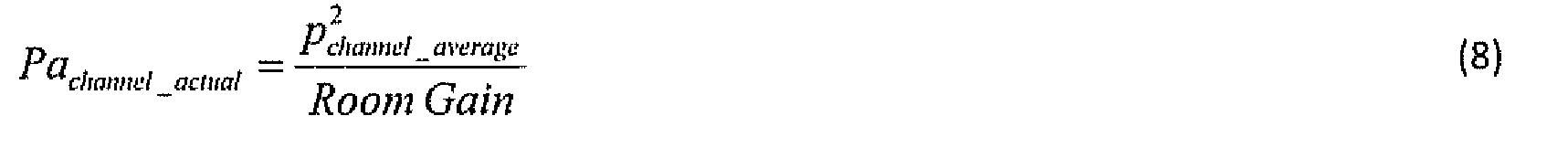
- the total acoustic power output from the loudspeaker driver(s) for a given content channel can be calculated from the power averaged sound pressure and the measured Room Gain by using equation 8.
- This target function may also include the difference between a desired Room Gain and the actual Room Gain measured in the room/enclosure.
- a desired Room Gain may also be fixed, selectable or adaptive to the actual room.
- the desired Room Gain is equal to the actual Room Gain, i.e. preserving the natural Room Gain in the actual room.
- An alternative embodiment is to use a desired Room Gain equal to the Room Gain in a particular room of choice, e.g.. an IEC 268-13 standard listening room.
- a procedure of pre-shaping and aligning the response of the loudspeakers in the room/enclosure may precede all the measurements described in this document.
- Equation 10 gives the listening position interface equalization filter target.
- the radiation resistance in a reference listening position can be
- a listening position where the access to the sound field is considered to be optimal.
- a listening position where the step of pre-shaping and equalization before the procedure of adapting to the room/enclosure is optimized may be used for this reference.
- a preferred embodiment is, however, to use equal to the radiation
- Equation 1 1 now gives the complete equalization filter for an Adaptive Sound Field Control (ASFC) system according to the described embodiment of the invention.
- ASFC Adaptive Sound Field Control
- Loudspeaker drivers are known to change as a function of aging and environment changes like temperature and humidity. Also playing loud music will heat the loudspeaker drive units and in particular the voice coils, which will also change the characteristics of the drive units .
- Changing the acoustic properties of the room/enclosure can occur for numerous reasons, for instance as a consequence of how many people are present in the room/enclosure, opening or closing a window/door, opening or closing the roof in a car, fitting more or less furniture/baggage etc. into the room/enclosure.
- Using room adaptation according to the present invention provides a new possibility of tracking such changes in real time.
- the whole procedure can be repeated under different configurations, e.g. open/closed windows, and the corresponding equalization filters can be stored and selected manually or automatically when the same configuration happens during use. Alternatively, the whole or a part of the procedure can be performed during actual use in the actual configuration.
- a subset of the random positions is chosen that has been proved to contain the major part of information obtained by the full set of random positions.
- a subset of 3 positions can be selected to track the changes due to changes in loudspeaker drive units and/or acoustic properties in the room/enclosure. This is shown in figure 6.
- the three positions are sufficient when combining with the knowledge obtained in the full set of random positions in an initial design or calibration step.
- the initial or calibration step may be a collection of measurements in different configurations that can be manually selected or automatically selected when the configuration changes.
- Figure 6 shows a real time adaptation tracking changes from measurement of sound pressure at a subset of random position, e.g. three positions.
- those parts of the filter that are determined by means of the dedicated measurement loudspeaker 14 either located at the described position used for determining room gain RG(f) or for determining the listening position interface are preferably pre-recorded during an initial or calibration phase, as the measurement of pi and p2 in front of the measurement loudspeaker and/or the use of a measurement loudspeaker at different positions in the enclosure would be difficult or in some situations even impossible to implement during actual operation.
- these quantities are determined for all relevant conditions in the particular enclosure, whereas the acoustic power output from the one or more loudspeakers 2, 3, 4 can be estimated during actual operation, for instance by means of the simplified three-microphone setup shown in Figure 6, which only applies three microphones, whereas a larger number of microphones (or measurement positions) is typically used in the initial or calibration phase.
- a larger number of microphones or measurement positions
- nine measurement positions are used in this phase.
- an event can activate the adaption procedure to take place.
- the event is a trigger to start the adaption algorithm and to perform the measurements, with the three microphones for instance, the calculations and the adjustments accordingly.
- the trigger may be of different types according to actual product requirements e.g. but not limited to: a) automatically when the car is entered or the engine is started, or b) upon a specific control command given by the user.
- the command given by the user may be e.g. a pressure on button, a touch on a touch panel, a spoken command or a given gesture from a hand or the like.
- the information about the mode of the adaption procedure may be displayed, with an indication of the transition from off -> initiated -> completed -> active.
- the type of display may e.g. be a LCD screen, an OLED panel, an LED or the like.
- a combined key input device switch button
- display device an LED with multiple colour mode indications
Landscapes
- Physics & Mathematics (AREA)
- Engineering & Computer Science (AREA)
- Acoustics & Sound (AREA)
- Signal Processing (AREA)
- Health & Medical Sciences (AREA)
- General Health & Medical Sciences (AREA)
- Otolaryngology (AREA)
- Stereophonic System (AREA)
- Soundproofing, Sound Blocking, And Sound Damping (AREA)
Abstract
The present invention relates to a method for controlling one or more loudspeakers provided in an enclosure, such as a listening room or an automobile cabin, the method comprising the steps of: (i) providing said one or more loudspeakers (2, 3, 4) with an audio input signal (5) whereby a sound field (10) is generated in the enclosure (1), and determining the corresponding acoustic power output APO(f) emitted from the one or more loudspeakers (2, 3, 4) into said enclosure (1); (ii) determining an acoustic contribution or room gain RG(f) of the enclosure (1) to the generated sound field (10); (iii) optionally determining a listening position interface LPI(f) that characterises a listener's ability to receive sound energy from a sound field at the specific place in the sound Field, in which he is located; and (iv) determining a filter characteristic as a function of the acoustic power output, the acoustic contribution or room gain RG(f) of the enclosure to the sound field in the enclosure and optionally the listening position interface between the sound field at the listening position and a listener placed at this position. The invention furthermore relates to a system for carrying out the above method and specifically to the use of the method and system for obtaining optimal audio reproduction in confined spaces such as automobile cabins.
Description
ADAPTIVE SOUND FIELD CONTROL
TECHNICAL FIELD
The invention relates generally to a method and a system for controlling loudspeakers in a room and more specifically to such methods and systems optimised for use in small and/or closed enclosures, such as the cabin of a vehicle, for instance a car.
BACKGROUND OF THE INVENTION
Methods and systems having the capability to adjust a speaker system to its environment are known within the art. Such methods and systems comprise for instance single point room equalization, obtained by measuring sound pressure in one point near the listening position and subsequent direct inverse filtering. Another prior art procedure comprises adjusting a loudspeaker to its acoustic environment and controlling the acoustic energy in the sound field. Still another procedure comprises adjusting the loudspeaker according to the listening position.
SUMMARY OF THE INVENTION
According to a first aspect of the present invention there is provided a method for controlling one or more loudspeakers provided in an enclosure, such as a listening room or an automobile cabin, the method comprising the steps of:
(i) providing said one or more loudspeakers with an audio input signal whereby a sound field is generated in the enclosure, and determining the corresponding acoustic power output APO(f) emitted from the one or more loudspeakers into said enclosure;
(ii) determining an acoustic contribution or room gain RG(f) of the enclosure to the generated sound field;
(iii) optionally determining a listening position interface LPI(f) that characterises a listener's ability to receive sound energy from a sound field at the specific place in the sound field, in which he is located;
(iv) determining a filter characteristic as a function of the acoustic power output, the acoustic contribution of the enclosure to the sound field in the enclosure and optionally the listening position interface between the sound field at the listening position and a listener placed at this position, According to an embodiment of the method according to the invention, the acoustic power output APO(f) from the one of more loudspeakers is determined by power averaging of measured sound pressures at a plurality of random positions scattered over substantially the entire internal space of said enclosur e.
According to an embodiment of the method according to the invention, the acoustic contribution RG(f) of the enclosure to the sound field in the enclosure is determined by carrying out the following steps:
(i) placing a sound source, such as a dedicated measurement loudspeaker, at a measurement position in the enclosure;
(ii) measuring sound pressure at a plurality of positions within the enclosure while emitting an acoustic signal by means of said sound source;
(iii) calculating the power averaged sound pressure of the sound pressures at said plurality of positions;
(iv) while keeping the sound source at said measurement position, measuring sound pressures p\ and pi at two different positions in the near field of the sound source; (v) based on the measured sound pressures at said two positions calculating the radiation resistance Rr in the near field of the sound source;
(vi) based on said radiation resistance Rr calculating the acoustic power output from the sound source;
(vii) calculating said acoustic contribution of the enclosure to the generated sound field as the ratio between the square of the power averaged sound pressure of the sound pressures at said plurality of positions and said acoustic power output from the measurement sound source.
According to an embodiment of the method according to the invention, said listening position interface LPI(f) is determined by placing a measurement sound source at an actual listening position in said room or enclosure and calculating the radiation resistance in the
near field of the measurement sound source based on measurements of sound pressures p\ and p2, respectively, at two positions, respectively, The listening position interface is then determined as a function of the ratio between the radiation resistance determined at a reference listening position and the radiation resistance determined at said actual listening position.
According to a specific embodiment of the method according to the invention, the listening position interface is the square root of the ratio between the radiation resistance determined at a reference listening position and the radiation resistance determined at said actual listening position. According to a specific embodiment of the method according to the invention, the reference listening position is a position in free field.
According to an embodiment of the method according to the invention, said filter characteristic is determined as the product of a speaker equalization filter, Speaker(f), and a listening position interface equalization filter, Listener(f), wherein the speaker equalization filter ensures the generation of a desired sound field in the enclosure while the listening position interface equalization filter compensates for the actual access at the listening position to the generated sound field.
According to an advantageous embodiment of the method according to the invention, a first subset of those quantities that are needed for determining the speaker equalization filter, Speaker(f), and the listening position interface equalization filter, Listener(f), are measured during an initial calibration process and stored in storage means corresponding to different conditions of the enclosure, and a second subset of said quantities is determined in teal time during actual use of the enclosure. According to a particularly advantageous embodiment, said second subset of quantities is determined in fewer positions in the enclosure than those used for determining the same quantities during said initial calibration process.
According to a second aspect of the present invention, there is provided a system for controlling one or more loudspeakers provided in an enclosure, such as a listening room or an automobile cabin, the system comprising:
(a) one or more microphones for measuring sound pressure at different positions in a sound field in an enclosure;
(b) a measurement sound source that can be placed at chosen positions in said sound field in said enclosure;
(c) means for, based on said measured sound pressures, determining the acoustic power output APO(f) emitted from one or more loudspeakers into said enclosure, said one or more loudspeakers generating a sound field in the enclosure;
(d) means for determining an acoustic contribution RG(f) of the enclosure to the generated sound field based on a sound signal emitted by said measurement sound source and the measurement of sound pressure in the near field of said measurement sound source at two positions at different distances from the measurement sound source;
(e) means for determining a listening position interface LPI(f) that characterises a listener's ability to receive sound energy from a sound field at the specific place in the sound field, in which he is located, said determination of ILP(f) being based on a sound signal emitted by said measurement sound source and the measurement of sound pressure in the near field of said measurement sound source at two positions at different distances from the measurement sound source, where the measurement sound source is placed at a listener position in said enclosure,
(f) means for determining a filter characteristic as a function of the acoustic power output, the acoustic contribution of the enclosure to the sound field in the enclosure and the listening position interface between the sound field at the listening position and a listener placed at this position.
According to an embodiment of the system of the invention, said filter characteristic is a function of a speaker equalization filter, Speaker(f), and a listening position interface equalization filter, Listener(f).
According to an embodiment of the system of the invention, the system further comprises means for storing said speaker equalization filter, Speaker(f), and said listening position interface equalization filter, Listener(f) corresponding to different conditions of said enclosure, or means for storing those quantities that are derived from measurements of said sound pressures in the enclosure and that are used for determining the speaker equalization filter, Speaker(f), and a listening position interface equalization filter, Listener(f). According to an advantageous embodiment of the system according to the invention, the system further comprises a set of microphones that can carry out real time measurements of sound pressure during use of the enclosure and use these measurements together with
appropriately stored quantities to determine real time changes of said filter characteristic or said speaker equalization filter, Speaker(f), and a listening position interface equalization filter, Listener(f).
According to still an advantageous embodiment of the system according to the invention, the system further comprises means for triggering said real time changes of filter characteristics, for instance when the acoustic properties of the enclosure change, or when the acoustic properties of the loudspeakers that create the acoustic field in the enclosure change- Said triggering is performed manually by an operator, such as by the driver or a passenger in a car or performed automatically, for instance by opening of a window in a car, or when the number of persons in the cabin changes.
The present invention differentiates from the prior art at least with respect to the following aspects:
- Adjustment of the performance in the full audible frequency range.
- According to the invention there are provided a number of individual options for adjustment, such as:
- Acoustic power output (distributed energy);
- Room gain, which may vary according to the actual room design;
- Optimal listening position;
- Listening position combined with supplemental measurements in several positions; - Real-time adaption, by applying a subset of measurement points from the complete set of possible measurement points;
- Pre-shaped adjustments according to predefined knowledge data.
A specific embodiment of the method and system according to the invention will be described in detail in the following, but it is understood that other embodiments, for instance of the various functional entities used in the method and system would also be possible and would fall within the scope of the present invention.
BRIEF DESCRIPTION OF THE DRAWINGS
The present invention will be better understood by reading the following detailed description of an embodiment of the invention in conjunction with the drawings, wherein:
Figure 1 shows the three main elements (the acoustic power output from the loudspeakers, the room gain and the listening position interface) of the present invention;
Figure 2 shows sampling of energy or power in a sound field in a room;
Figure 3 shows the measurement of room gain in a room or enclosure by using a special measurement loudspeaker that could be placed at any position in the room or enclosure;
Figure 4 shows an example of a special measurement loudspeaker placed in a car at one of the listening positions. The measurement loudspeaker is fitted with special means to allow easy and reproducible measurement of sound pressure in two positions in the close near field of the loudspeaker diaphragm;
Figure 5 shows measuring the listening position interface at a particular listening position; and Figure 6 shows real time adaptation that tracks changes of the energy or power in the sound field based on measurements of sound pressure at a subset of random positions, for instance three positions as shown in this figure,
DETAILED DESCRIPTION OF THE INVENTION In the following, a specific embodiment of the invention will be described in detail, but it is understood that this embodiment only constitutes an example of how the general concepts of the present invention can be implemented in practice.
A basic concept of the present invention is that the total transmission path from the electrical input terminals) of the loudspeakers) to the sound pressure generated at the ears of a listener in an enclosure can be described to constitute three main elements: (i) the acoustic power emitted from the one or more loudspeakers into the enclosure when the one or more loudspeakers are provided with electrical input signals, (ii) the influence of the acoustic properties of the enclosure itself on the sound field created in the enclosure, i.e. on the distribution of sound pressure and hence on average sound pressure generated in the
enclosure by the one or more loudspeakers emitting acoustic power into the enclosure, and (iii) the coupling or interface between the created sound field in the enclosure and a listener located at a given position in the enclosure. This is illustrated with reference to figure 1 that shows the three elements that participate in creating a sound field 10 in an enclosure 1 such as a listening room or automobile cabin. An example of how these three elements can be measured in practice is illustrated with reference to figures 2 through 6.
As shown in figure 1 , one or more loudspeaker drive units 2, .3, 4 emit a total acoustic power into the sound field 10 depending on the coupling to the sound field 10 from each driver position and the interaction between the drive units Depending on the acoustic properties of the listening room/enclosure, more or less power averaged sound pressure will be created in the room/enclosure for a given acoustic power output into the sound field. In order to characterize the influence of the room on the sound field generated herein, the quantity room gain is introduced. Room Gain is here defined as the ratio between the squared power averaged sound pressure in a room and the acoustic power into this room.
A listener's access to the sound field 10, i.e. his ability to receive sound energy from a sound field and at the specific place herein in which he is located, depends on the coupling to the sound field at the actual listening position, A listener is in figure 1 schematically indicated by the head 6. This coupling can be described by the radiation resistance at the listening position, for instance measured by placing a loudspeaker (14 in figures 3, 4 and 5) in the listening position and measuring the radiation resistance seen by this loudspeaker into the sound field.
Below follows a detailed description of methods for calculating the above three contributions to the total transmission path and how to determine an electronic filter for obtaining a specific target transmission from the electrical input to the loudspeakers to the ears of the listener.
Figure 2 shows how the energy or power in a sound field can be measured by power averaging a number of measured sound pressures at random positions 9 scattered across the entire space in both x, y and z directions (length, width and height directions). It is understood that although the figures represent the sound field in only two dimensions, the actual field will of course be three-dimensional, and measurement points generally should be distributed throughout the three-dimensional space. Equation 1 below shows how to calculate the power averaged sound pressure. The number of random positions must be
higher than 1 and in a preferred embodiment it will be 9 positions, but good results can be obtained with 4 positions .

channel.
 p is the measured transfer function from the input 5 to a power amplifier (not shown) to the sound pressure at the i'th random position, for instance the one designated by 9' in figure 2.
Figure 3 illustrates a method of measuring the room gain in a room/enclosure by using a special measurement loudspeaker 14 that can be placed anywhere in the room.
After placing the special measurement loudspeaker 14 at a chosen position in the room/enclosure as shown in figure 3, sound pressure at a number of random positions 1 1 is measured while emitting acoustic signals through the measurement loudspeaker 14. Equation 2 shows how to calculate the power averaged sound pressure of the sound

pressures at these random positions.

is the power averaged sound pressure when emitting acoustic signals through the

special measurement loudspeaker 14 (the abbreviation RG stands for Room Gain). Figure 4 shows a practical example of such a special measurement loudspeaker mounted at a specific location in an automobile cabin. pRG_i is the transfer function between the inputs to the power amplifier to the measured sound pressure at the i'th random position. (It should be noted that throughout this specification, all generated sound pressures are normalised with respect to the input voltage to the respective amplifiers, it is hence correct to designate for instance the quantity PRG > as a transfer function).
While keeping the measurement loudspeaker 14 in the same position (see figure 3), the transfer function from the input of the power amplifier to the sound pressure at two positions 12 and 13 differently spaced from the loudspeaker diaphragm but both in the very near field of the diaphragm is then measured. The distance from the diaphragm to the closest position 12, in which position the sound pressure pt is measured, could be e.g 4 cm while the distance to the other position, in which position the sound pressure p2 is measured, could be e.g. 9 cm. Equation 3 shows how to calculate the mechanical radiation resistance, Rm r = Re(Zm,r), from the two sound pressures pi and pi in the near field of the measurement loudspeaker 14.
 g is a real valued constant describing the scaling due to geometry etc. But g is unimportant in the application and can be set to 1. Figure 4 displays one example of a special measurement loudspeaker 14 placed in a car at one of the listening positions. The measurement loudspeaker 14 is fitted with special means 15 to allow easy and reproducible measurement of sound pressure in two positions in the close near field of the loudspeaker diaphragm .
After calculating the mechanical radiation resistance from equation 3 it is possible to calculate the acoustic power output using equation 4.


Figure 5 shows how the special measurement loudspeaker 14 is used to determine the listening position interface at a particular listening position. This measurement can be repeated for as many listening positions as desired. Individual filters can then be designed for each listening position or an average filter can be designed. According to a specific embodiment of the invention, the listening position interface filter is left out, whereby a global equalizing can then be designed. The listening position interface and the corresponding part of the speaker equalization filter, Listener(f), is hence to be regarded as an option.
The listening position interface is obtained from a similar measurement of two sound pressures at positions 12 and 13, respectively, in near field of the measurement loudspeaker. Again equation 3 can be used to calculate the mechanical radiation resistance from the two measured sound pressures. Adaptive Sound Field Control Equalization Filters:
The total equalization filter is split into two main components: a speaker equalization filter and a listening position interface equalization filter as described in equation 7,

The speaker equalization filter ensures generation of a desired sound field in the room/enclosure while the listening position interface equalization filter compensates for the actual access to the generated sound field.
The total acoustic power output from the loudspeaker driver(s) for a given content channel can be calculated from the power averaged sound pressure and the measured Room Gain by using equation 8.
Then the speaker equalization filter can be calculated from equation 9,

selectable or adaptive as a function of the measured total acoustic power output. This target function may also include the difference between a desired Room Gain and the actual Room Gain measured in the room/enclosure. A desired Room Gain may also be fixed, selectable or adaptive to the actual room. According to one embodiment of the invention, the desired Room Gain is equal to the actual Room Gain, i.e. preserving the natural Room Gain in the actual room. An alternative embodiment is to use a desired Room Gain equal to the Room Gain in a particular room of choice, e.g.. an IEC 268-13 standard listening room. A procedure of pre-shaping and aligning the response of the loudspeakers in the room/enclosure may precede all the measurements described in this document. This is equivalent to designing the basic loudspeaker in a particular room different or equal to the room of usage before applying this procedure for adapting to the actual room/enclosure of usage, E.g. a general trend of decreasing level with increasing frequency can be imposed onto the loudspeaker system before starting the described procedure for adapting the loudspeaker to the room/enclosure. Another example is performing dedicated equalization on a specific loudspeaker driver to correct known problems with that loudspeaker driver, which may be independent of the actual room of usage. Also specific equalization in the actual room/enclosure of usage may be applied before the room adaptation procedure is started. Equation 10 gives the listening position interface equalization filter target.
 The radiation resistance in a reference listening position, can be

measured in a listening position where the access to the sound field is considered to be optimal. E.g. a listening position where the step of pre-shaping and equalization before the procedure of adapting to the room/enclosure is optimized may be used for this reference. A preferred embodiment is, however, to use equal to the radiation

resistance in free field because in free field, a listener has equal access to all frequencies. The theoretical radiation resistance in free field for a point source is frequency squared multiplied by a constant depending on geometry.
Equation 1 1 now gives the complete equalization filter for an Adaptive Sound Field Control (ASFC) system according to the described embodiment of the invention.

A special case is when no specific listening position is considered, i.e. equalization globally valid to the whole room/enclosure. Then the total equalization filter reduces to the speaker equalization filter, as in equation 32.

Real time adaptation
Another aspect of the present invention is the possibility of real time adaption to any changes of loudspeaker drivers and acoustic properties of the room/enclosure. Loudspeaker drivers
are known to change as a function of aging and environment changes like temperature and humidity. Also playing loud music will heat the loudspeaker drive units and in particular the voice coils, which will also change the characteristics of the drive units .
Changing the acoustic properties of the room/enclosure can occur for numerous reasons, for instance as a consequence of how many people are present in the room/enclosure, opening or closing a window/door, opening or closing the roof in a car, fitting more or less furniture/baggage etc. into the room/enclosure. Using room adaptation according to the present invention provides a new possibility of tracking such changes in real time. The whole procedure can be repeated under different configurations, e.g. open/closed windows, and the corresponding equalization filters can be stored and selected manually or automatically when the same configuration happens during use. Alternatively, the whole or a part of the procedure can be performed during actual use in the actual configuration.
According to a preferred embodiment of the present invention, a subset of the random positions is chosen that has been proved to contain the major part of information obtained by the full set of random positions. Experiments show that a subset of 3 positions can be selected to track the changes due to changes in loudspeaker drive units and/or acoustic properties in the room/enclosure. This is shown in figure 6.
The three positions are sufficient when combining with the knowledge obtained in the full set of random positions in an initial design or calibration step. The initial or calibration step may be a collection of measurements in different configurations that can be manually selected or automatically selected when the configuration changes.
Figure 6 shows a real time adaptation tracking changes from measurement of sound pressure at a subset of random position, e.g. three positions.
In order to be able to carry out the adaptation in real time, i.e. during actual operation of for instance an automobile, those parts of the filter that are determined by means of the dedicated measurement loudspeaker 14 either located at the described position used for determining room gain RG(f) or for determining the listening position interface, are preferably pre-recorded during an initial or calibration phase, as the measurement of pi and p2 in front of the measurement loudspeaker and/or the use of a measurement loudspeaker at different positions in the enclosure would be difficult or in some situations even impossible to implement during actual operation. Hence, according to a preferred embodiment of the invention, in an initial or calibration phase these quantities are determined for all relevant conditions in the particular enclosure, whereas the acoustic power output from the one or
more loudspeakers 2, 3, 4 can be estimated during actual operation, for instance by means of the simplified three-microphone setup shown in Figure 6, which only applies three microphones, whereas a larger number of microphones (or measurement positions) is typically used in the initial or calibration phase. With reference to figures 2 and 3, respectively, nine measurement positions are used in this phase.
For instance, an event can activate the adaption procedure to take place. The event is a trigger to start the adaption algorithm and to perform the measurements, with the three microphones for instance, the calculations and the adjustments accordingly. The trigger may be of different types according to actual product requirements e.g. but not limited to: a) automatically when the car is entered or the engine is started, or b) upon a specific control command given by the user.
The command given by the user may be e.g. a pressure on button, a touch on a touch panel, a spoken command or a given gesture from a hand or the like.
The information about the mode of the adaption procedure may be displayed, with an indication of the transition from off -> initiated -> completed -> active. The type of display may e.g. be a LCD screen, an OLED panel, an LED or the like.
In the preferred embodiment, a combined key input device (switch button) and display device (an LED with multiple colour mode indications) constitute the user interface to the adaption procedure.
Claims
1. A method for controlling one or more loudspeakers provided in an enclosure, such as a listening room or an automobile cabin, the method comprising the steps of: (i) providing said one or more loudspeakers (2, 3, 4) with an audio input signal (5) whereby a sound field (10) is generated in the enclosure (1), and determining the corresponding acoustic power output APO(f) emitted from the one or more loudspeakers (2, 3, 4) into said enclosure ( 1 );
(ii) determining an acoustic contribution or room gain RG(f) of the enclosure (1) to the generated sound field (10);
(iij) optionally determining a listening position interface LPI(f) that characterises a listener's ability to receive sound energy from a sound field at the specific place in the sound field, in which he is located;
(iv) determining a filter characteristic as a function of the acoustic power output, the acoustic contribution or room gain RG(f) of the enclosure to the sound filed in the enclosure and optionally the listening position interface between the sound field at the listening position and a listener placed at this position,.
2. A method according to claim 1 , wherein said acoustic power output APO(f) is determined based on power averaging of measured sound pressures at N positions scattered over the internal space of said enclosure.
3. A method according to claim 1 , wherein said acoustic contribution or room gain RG(f) of the enclosure to the sound field in the enclosure is determined by carrying out the following steps:
(i) placing a measurement sound source (14) at a measurement position in said enclosure (1 ); (ii) measuring sound pressure at M positions (1 1) while emitting an acoustic signal by means of said measurement sound source (14);
(iii) calculating the power averaged sound pressure of said sound pressures at said M positions (1 1 ); (vi) while keeping said measurement sound source (14) at said measurement position, measuring sound pressures pi and pi, respectively, at two positions ( 12) and (13), respectively, in the near field of the measurement sound source ( 14);
(v) based on the measured sound pressures at said two positions (12, 13), calculating the radiation resistance in the near field of the measurement sound source (14);
(vi) based on said radiation resistance, calculating the acoustic power output from the measurement sound source (14);
(vii) calculating said acoustic contribution or room gain RG(f) of the enclosure ( I ) to the generated sound field (10) as the ratio between the square of the power averaged sound pressure of the sound pressures at said M positions ( 1 1 ) and said acoustic power output from the measurement sound source (14).
4. A method according to claim 1, wherein said listening position interface LPl(f) is determined by placing a measurement sound source (14) at an actual listening position in said room or enclosure and calculating the radiation resistance in the near field of the measurement sound source (14) based on measurements of sound pressures p\ and pi, respectively, at two positions (12) and (13), respectively, and wherein the listening position interface is a function of the ratio between the radiation resistance determined at a reference listening position and the radiation resistance determined at said actual listening position.
5. A method according to claim 4, wherein the listening position interface is the square root of said ratio.
6. A method according to claim 4 or 5, wherein said reference listening position is a position in free field.
7. A method according to any of the preceding claims, wherein said filter characteristic is determined as the product of a speaker equalization filter, Speaker(f), and a function G, where G is either a function of frequency G(f) or a constant, which constant specifically can be equal to unity, and wherein the speaker equalization filter ensures the generation of a desired sound field in the enclosure (1).
8. A method according to claim 7, wherein said speaker equalization filter, Speaker(f), is determined by the expression:  where
where  is a desired target function for the acoustic power output, which target function may be fixed, selectable or adaptive
9. A method according to any of the preceding claims, comprising the steps of: (i) during an initial or calibration phase, measuring said acoustic contribution or room gain RG(f) and optionally the listening position interface for different conditions of said enclosure and storing the measurement results in storage means;
(ii) either during said initial or calibration phase determining said power average of measured sound pressures for one or more of said different conditions of said enclosure and storing the measurement results in storage means; or during said initial or calibration phase determining said power average of measured sound pressures for one condition, such as a reference condition, of said enclosure and storing the measurement result in storage means and during actual use of the loudspeakers (2, 3, 4) in the enclosure carrying out measurements of said sound pressures for up-dating the power averaged sound pressures, thereby to carry out up-dating of said filter characteristic to correspond to changed conditions of the enclosure
10, A method according to claim 9, wherein the number Nu of measurement positions used for real-time updating of the filter characteristic is less than the corresponding number N used in the initial or calibration phase.
1 1. A method according to claim 10, wherein N„ is equal to 3.
12. A system for controlling one or more loudspeakers provided in an enclosure, such as a listening room or an automobile cabin, the system comprising:
(a) one or more microphones for measuring sound pressure at different positions (9, 1 1 ) in a sound field ( 10) in an enclosure ( 1 ); (b) a measurement sound source (14) that can be placed at chosen positions in said sound field ( 10) in said enclosure ( 1 );
(c) means for, based on said measured sound pressures, determining the acoustic power output APO(f) emitted from one or more loudspeakers (2, 3, 4) into said enclosure (1), said one or more loudspeakers (2, 3, 4) generating a sound field (10) in the enclosure (1 ); (d) means for determining an acoustic contribution or room gain RG(f) of the enclosure ( 1 ) to the generated sound field (10) based on a sound signal emitted by said measurement sound source (14) and the measurement of sound pressure at two positions at different distances from the measurement sound source (14) in the near field of a sound field generated by said measurement sound source ( 14);
(e) optionally means for determining a listening position interface LPI(f) that characterises a listener's ability to receive sound energy from a sound field at the specific place in the sound field, in which he is located, said determination of ILP(f) being based on a sound signal emitted by said measurement sound source (14) and the measurement of sound pressure in the near field of a sound field generated by said measurement sound source (14) at two positions at different distances from the measurement sound source (14), where the measurement sound source (14) is placed at a listener position in said enclosure (1).
(f) means for determining a filter characteristic as a function of the acoustic power output, the acoustic contribution of the enclosure to the sound field in the enclosure and optionally the listening position interface between the sound field at the listening position and a listener placed at this position.
13. A system according to claim 12, wherein said filter characteristic is a function of a speaker equalization filter, Speaker(f), and a listening position interface equalization filter, Listener(f).
14, A system according to claim 13, further comprising means for storing said speaker equalization filter, Speaker(f), and optionally a listening position interface equalization filter, Listener(f) corresponding to different conditions of said enclosure (1 ), or means for storing those quantities that are derived from measurements of said sound pressures in the enclosure and that are used for determining the speaker equalization filter, Speaker(f), and a listening position interface equalization filter, Listener(f).
15. A system according to claim 14, further comprising a set of microphones that can carry out real time measurements of sound pressure during use of the enclosure and use these measurements together with appropriately stored quantities to determine real time changes of said filter characteristic or said speaker equalization filter, Speaker(f), and optionally a listening position interface equalization filter, Listener(f).
16 A system according to claim 14 or 15 further comprising means for triggering said real time changes of filter characteristics, for instance when the acoustic properties of the enclosure change, or when the acoustic properties of the loudspeakers (2, 3, 4) that create the acoustic field (10) in the enclosure (1 ) change,
17, A system according to claim 16, wherein said triggering is performed manually by an operator, such as by the driver or a passenger in a car,
18, A system according to claim 16, wherein said triggering is performed automatically, for instance by opening of a window in a car or when the number of persons in the cabin is changed,
19. The use of the system according to any of the claims 12 to 18 for implementing the method according to any of the claims 1 to 1 1
20. The method according to any of the preceding claims 1 to 1 1 , or the system according to any of the preceding claims 12 to 18 or the use of the system according to claim 19, wherein said enclosure is the cabin of vehicle, such as a car.
Priority Applications (3)
| Application Number | Priority Date | Filing Date | Title |
|---|---|---|---|
| US13/702,120 US9065411B2 (en) | 2010-07-09 | 2010-12-06 | Adaptive sound field control |
| CN201080067354.8A CN103733648A (en) | 2010-07-09 | 2010-12-06 | Adaptive sound field control |
| EP10788313.4A EP2591617B1 (en) | 2010-07-09 | 2010-12-06 | Adaptive sound field control |
Applications Claiming Priority (2)
| Application Number | Priority Date | Filing Date | Title |
|---|---|---|---|
| DKPA201000609 | 2010-07-09 | ||
| DKPA201000609 | 2010-07-09 |
Publications (1)
| Publication Number | Publication Date |
|---|---|
| WO2012003894A1 true WO2012003894A1 (en) | 2012-01-12 |
Family
ID=43629581
Family Applications (1)
| Application Number | Title | Priority Date | Filing Date |
|---|---|---|---|
| PCT/EP2010/068934 WO2012003894A1 (en) | 2010-07-09 | 2010-12-06 | Adaptive sound field control |
Country Status (4)
| Country | Link |
|---|---|
| US (1) | US9065411B2 (en) |
| EP (1) | EP2591617B1 (en) |
| CN (1) | CN103733648A (en) |
| WO (1) | WO2012003894A1 (en) |
Cited By (3)
| Publication number | Priority date | Publication date | Assignee | Title |
|---|---|---|---|---|
| WO2014091027A2 (en) * | 2012-12-14 | 2014-06-19 | Bang & Olufsen A/S | A method and an apparatus for determining one or more parameters of a room or space |
| US10395668B2 (en) | 2017-03-29 | 2019-08-27 | Bang & Olufsen A/S | System and a method for determining an interference or distraction |
| US10469046B2 (en) | 2017-03-10 | 2019-11-05 | Samsung Electronics Co., Ltd. | Auto-equalization, in-room low-frequency sound power optimization |
Families Citing this family (62)
| Publication number | Priority date | Publication date | Assignee | Title |
|---|---|---|---|---|
| US11106424B2 (en) | 2003-07-28 | 2021-08-31 | Sonos, Inc. | Synchronizing operations among a plurality of independently clocked digital data processing devices |
| US11650784B2 (en) | 2003-07-28 | 2023-05-16 | Sonos, Inc. | Adjusting volume levels |
| US8290603B1 (en) | 2004-06-05 | 2012-10-16 | Sonos, Inc. | User interfaces for controlling and manipulating groupings in a multi-zone media system |
| US8234395B2 (en) | 2003-07-28 | 2012-07-31 | Sonos, Inc. | System and method for synchronizing operations among a plurality of independently clocked digital data processing devices |
| US11106425B2 (en) | 2003-07-28 | 2021-08-31 | Sonos, Inc. | Synchronizing operations among a plurality of independently clocked digital data processing devices |
| US8086752B2 (en) | 2006-11-22 | 2011-12-27 | Sonos, Inc. | Systems and methods for synchronizing operations among a plurality of independently clocked digital data processing devices that independently source digital data |
| US11294618B2 (en) | 2003-07-28 | 2022-04-05 | Sonos, Inc. | Media player system |
| US10613817B2 (en) | 2003-07-28 | 2020-04-07 | Sonos, Inc. | Method and apparatus for displaying a list of tracks scheduled for playback by a synchrony group |
| US9374607B2 (en) | 2012-06-26 | 2016-06-21 | Sonos, Inc. | Media playback system with guest access |
| US9977561B2 (en) | 2004-04-01 | 2018-05-22 | Sonos, Inc. | Systems, methods, apparatus, and articles of manufacture to provide guest access |
| US8868698B2 (en) | 2004-06-05 | 2014-10-21 | Sonos, Inc. | Establishing a secure wireless network with minimum human intervention |
| US8326951B1 (en) | 2004-06-05 | 2012-12-04 | Sonos, Inc. | Establishing a secure wireless network with minimum human intervention |
| US8483853B1 (en) | 2006-09-12 | 2013-07-09 | Sonos, Inc. | Controlling and manipulating groupings in a multi-zone media system |
| US9202509B2 (en) | 2006-09-12 | 2015-12-01 | Sonos, Inc. | Controlling and grouping in a multi-zone media system |
| US8788080B1 (en) | 2006-09-12 | 2014-07-22 | Sonos, Inc. | Multi-channel pairing in a media system |
| US11265652B2 (en) | 2011-01-25 | 2022-03-01 | Sonos, Inc. | Playback device pairing |
| US11429343B2 (en) | 2011-01-25 | 2022-08-30 | Sonos, Inc. | Stereo playback configuration and control |
| US9084058B2 (en) | 2011-12-29 | 2015-07-14 | Sonos, Inc. | Sound field calibration using listener localization |
| US9729115B2 (en) | 2012-04-27 | 2017-08-08 | Sonos, Inc. | Intelligently increasing the sound level of player |
| US9668049B2 (en) | 2012-06-28 | 2017-05-30 | Sonos, Inc. | Playback device calibration user interfaces |
| US9706323B2 (en) | 2014-09-09 | 2017-07-11 | Sonos, Inc. | Playback device calibration |
| US9690271B2 (en) | 2012-06-28 | 2017-06-27 | Sonos, Inc. | Speaker calibration |
| US9219460B2 (en) | 2014-03-17 | 2015-12-22 | Sonos, Inc. | Audio settings based on environment |
| US9690539B2 (en) | 2012-06-28 | 2017-06-27 | Sonos, Inc. | Speaker calibration user interface |
| US9106192B2 (en) | 2012-06-28 | 2015-08-11 | Sonos, Inc. | System and method for device playback calibration |
| US8930005B2 (en) | 2012-08-07 | 2015-01-06 | Sonos, Inc. | Acoustic signatures in a playback system |
| US9008330B2 (en) | 2012-09-28 | 2015-04-14 | Sonos, Inc. | Crossover frequency adjustments for audio speakers |
| US20160073214A1 (en) * | 2013-04-24 | 2016-03-10 | Nissan Motor Co., Ltd. | Vehicle acoustic control device, and vehicle acoustic control method |
| US9226073B2 (en) | 2014-02-06 | 2015-12-29 | Sonos, Inc. | Audio output balancing during synchronized playback |
| US9226087B2 (en) | 2014-02-06 | 2015-12-29 | Sonos, Inc. | Audio output balancing during synchronized playback |
| US9264839B2 (en) | 2014-03-17 | 2016-02-16 | Sonos, Inc. | Playback device configuration based on proximity detection |
| US8995240B1 (en) | 2014-07-22 | 2015-03-31 | Sonos, Inc. | Playback using positioning information |
| US10127006B2 (en) | 2014-09-09 | 2018-11-13 | Sonos, Inc. | Facilitating calibration of an audio playback device |
| US9891881B2 (en) | 2014-09-09 | 2018-02-13 | Sonos, Inc. | Audio processing algorithm database |
| US9910634B2 (en) | 2014-09-09 | 2018-03-06 | Sonos, Inc. | Microphone calibration |
| US9952825B2 (en) | 2014-09-09 | 2018-04-24 | Sonos, Inc. | Audio processing algorithms |
| US10664224B2 (en) | 2015-04-24 | 2020-05-26 | Sonos, Inc. | Speaker calibration user interface |
| WO2016172593A1 (en) | 2015-04-24 | 2016-10-27 | Sonos, Inc. | Playback device calibration user interfaces |
| RU2612535C2 (en) * | 2015-05-14 | 2017-03-09 | БОГУСЛАВСКИЙ Евгений | Loudspeaker |
| US10248376B2 (en) | 2015-06-11 | 2019-04-02 | Sonos, Inc. | Multiple groupings in a playback system |
| US9538305B2 (en) | 2015-07-28 | 2017-01-03 | Sonos, Inc. | Calibration error conditions |
| US9693165B2 (en) | 2015-09-17 | 2017-06-27 | Sonos, Inc. | Validation of audio calibration using multi-dimensional motion check |
| CN111314826B (en) | 2015-09-17 | 2021-05-14 | 搜诺思公司 | Method performed by a computing device and corresponding computer readable medium and computing device |
| US10303422B1 (en) | 2016-01-05 | 2019-05-28 | Sonos, Inc. | Multiple-device setup |
| US9743207B1 (en) | 2016-01-18 | 2017-08-22 | Sonos, Inc. | Calibration using multiple recording devices |
| US11106423B2 (en) | 2016-01-25 | 2021-08-31 | Sonos, Inc. | Evaluating calibration of a playback device |
| US10003899B2 (en) | 2016-01-25 | 2018-06-19 | Sonos, Inc. | Calibration with particular locations |
| US9864574B2 (en) | 2016-04-01 | 2018-01-09 | Sonos, Inc. | Playback device calibration based on representation spectral characteristics |
| US9860662B2 (en) | 2016-04-01 | 2018-01-02 | Sonos, Inc. | Updating playback device configuration information based on calibration data |
| US9763018B1 (en) | 2016-04-12 | 2017-09-12 | Sonos, Inc. | Calibration of audio playback devices |
| US9860670B1 (en) | 2016-07-15 | 2018-01-02 | Sonos, Inc. | Spectral correction using spatial calibration |
| US9794710B1 (en) | 2016-07-15 | 2017-10-17 | Sonos, Inc. | Spatial audio correction |
| US10372406B2 (en) | 2016-07-22 | 2019-08-06 | Sonos, Inc. | Calibration interface |
| US10459684B2 (en) | 2016-08-05 | 2019-10-29 | Sonos, Inc. | Calibration of a playback device based on an estimated frequency response |
| US10712997B2 (en) | 2016-10-17 | 2020-07-14 | Sonos, Inc. | Room association based on name |
| US10299061B1 (en) | 2018-08-28 | 2019-05-21 | Sonos, Inc. | Playback device calibration |
| US11206484B2 (en) | 2018-08-28 | 2021-12-21 | Sonos, Inc. | Passive speaker authentication |
| DE102018121123B4 (en) * | 2018-08-29 | 2022-08-11 | Airbus Operations Gmbh | Automated self-test of cabin speakers |
| KR102663979B1 (en) | 2018-11-26 | 2024-05-09 | 엘지전자 주식회사 | Vehicle and its method of operation |
| US10734965B1 (en) | 2019-08-12 | 2020-08-04 | Sonos, Inc. | Audio calibration of a portable playback device |
| WO2021064736A1 (en) * | 2019-10-03 | 2021-04-08 | Carmel Haifa University Economic Corporation Ltd. | Adaptive acoustic chamber and method for acoustic calibration |
| CN117319902B (en) * | 2023-11-28 | 2024-03-12 | 广州市声讯电子科技股份有限公司 | Control method and control system for multi-scene loudspeaker array |
Citations (6)
| Publication number | Priority date | Publication date | Assignee | Title |
|---|---|---|---|---|
| EP0772374A2 (en) * | 1995-11-02 | 1997-05-07 | Bang & Olufsen A/S | Method and apparatus for controlling the performance of a loudspeaker in a room |
| WO2000021331A1 (en) * | 1998-10-06 | 2000-04-13 | Bang & Olufsen A/S | Environment adaptable loudspeaker |
| US6760451B1 (en) * | 1993-08-03 | 2004-07-06 | Peter Graham Craven | Compensating filters |
| WO2005109954A1 (en) * | 2004-05-06 | 2005-11-17 | Bang & Olufsen A/S | A method and system for adapting a loudspeaker to a listening position in a room |
| WO2007076863A1 (en) * | 2006-01-03 | 2007-07-12 | Slh Audio A/S | Method and system for equalizing a loudspeaker in a room |
| EP2161950A2 (en) * | 2008-09-08 | 2010-03-10 | Bang & Olufsen A/S | Configuring a sound field |
Family Cites Families (2)
| Publication number | Priority date | Publication date | Assignee | Title |
|---|---|---|---|---|
| JP4392513B2 (en) * | 1995-11-02 | 2010-01-06 | バン アンド オルフセン アクティー ゼルスカブ | Method and apparatus for controlling an indoor speaker system |
| EP1986466B1 (en) * | 2007-04-25 | 2018-08-08 | Harman Becker Automotive Systems GmbH | Sound tuning method and apparatus |
-
2010
- 2010-12-06 CN CN201080067354.8A patent/CN103733648A/en active Pending
- 2010-12-06 EP EP10788313.4A patent/EP2591617B1/en active Active
- 2010-12-06 WO PCT/EP2010/068934 patent/WO2012003894A1/en active Application Filing
- 2010-12-06 US US13/702,120 patent/US9065411B2/en active Active
Patent Citations (7)
| Publication number | Priority date | Publication date | Assignee | Title |
|---|---|---|---|---|
| US6760451B1 (en) * | 1993-08-03 | 2004-07-06 | Peter Graham Craven | Compensating filters |
| EP0772374A2 (en) * | 1995-11-02 | 1997-05-07 | Bang & Olufsen A/S | Method and apparatus for controlling the performance of a loudspeaker in a room |
| WO2000021331A1 (en) * | 1998-10-06 | 2000-04-13 | Bang & Olufsen A/S | Environment adaptable loudspeaker |
| EP1133896A1 (en) * | 1998-10-06 | 2001-09-19 | Bang & Olufsen A/S | Environment adaptable loudspeaker |
| WO2005109954A1 (en) * | 2004-05-06 | 2005-11-17 | Bang & Olufsen A/S | A method and system for adapting a loudspeaker to a listening position in a room |
| WO2007076863A1 (en) * | 2006-01-03 | 2007-07-12 | Slh Audio A/S | Method and system for equalizing a loudspeaker in a room |
| EP2161950A2 (en) * | 2008-09-08 | 2010-03-10 | Bang & Olufsen A/S | Configuring a sound field |
Non-Patent Citations (3)
| Title |
|---|
| ABILDGAARD PEDERSEN ET AL: "Loudspeaker-Room Adaptation for a Specific Listening Position using Information about the Complete Sound Field", AES CONVENTION 121; OCTOBER 2006, AES, 60 EAST 42ND STREET, ROOM 2520 NEW YORK 10165-2520, USA, 1 October 2006 (2006-10-01), XP040507831 * |
| ABILDGAARD PEDERSEN JAN ET AL: "Natural Timbre in Room Correction Systems", AES CONVENTION 122; MAY 2007, AES, 60 EAST 42ND STREET, ROOM 2520 NEW YORK 10165-2520, USA, 1 May 2007 (2007-05-01), XP040508184 * |
| JAN ABILDGAARD PEDERSEN: "Adjusting a loudspeaker to its acoustic environment", 5880, 10 October 2003 (2003-10-10), New York, pages 1 - 13, XP002627369, Retrieved from the Internet <URL:http://www.aes.org/e-lib/browse.cfm?elib=12471> [retrieved on 20110310] * |
Cited By (4)
| Publication number | Priority date | Publication date | Assignee | Title |
|---|---|---|---|---|
| WO2014091027A2 (en) * | 2012-12-14 | 2014-06-19 | Bang & Olufsen A/S | A method and an apparatus for determining one or more parameters of a room or space |
| WO2014091027A3 (en) * | 2012-12-14 | 2014-10-30 | Bang & Olufsen A/S | A method and an apparatus for determining one or more parameters of a room or space |
| US10469046B2 (en) | 2017-03-10 | 2019-11-05 | Samsung Electronics Co., Ltd. | Auto-equalization, in-room low-frequency sound power optimization |
| US10395668B2 (en) | 2017-03-29 | 2019-08-27 | Bang & Olufsen A/S | System and a method for determining an interference or distraction |
Also Published As
| Publication number | Publication date |
|---|---|
| EP2591617B1 (en) | 2014-06-18 |
| EP2591617A1 (en) | 2013-05-15 |
| US9065411B2 (en) | 2015-06-23 |
| US20130101137A1 (en) | 2013-04-25 |
| CN103733648A (en) | 2014-04-16 |
Similar Documents
| Publication | Publication Date | Title |
|---|---|---|
| US9065411B2 (en) | Adaptive sound field control | |
| US9264834B2 (en) | System for modifying an acoustic space with audio source content | |
| EP2324646B1 (en) | Efficiency optimized audio system | |
| US9380400B2 (en) | Optimizing audio systems | |
| JP5464715B2 (en) | Sound tuning method | |
| EP2394360B1 (en) | Adjusting dynamic range for audio reproduction | |
| EP2884489A1 (en) | Sound System including an Engine Sound Synthesizer | |
| CN103988525A (en) | Virtual audio system tuning | |
| EP2839678B1 (en) | Optimizing audio systems | |
| CN109413545A (en) | Rely on the adaptive tone color correction in room | |
| US20230134271A1 (en) | Method for Audio Processing | |
| KR20110010192A (en) | Apparatus and method for noise control | |
| CN103580630B (en) | automatic loudness control | |
| US20110268285A1 (en) | Sound image localization estimating device, sound image localization control system, sound image localization estimation method, and sound image localization control method | |
| EP3579582B1 (en) | Automatic characterization of perceived transducer distortion | |
| US20230199419A1 (en) | System, apparatus, and method for multi-dimensional adaptive microphone-loudspeaker array sets for room correction and equalization | |
| EP3025517B1 (en) | Automatic timbre control | |
| EP2579247B1 (en) | Methods and systems for measuring and reporting an energy level of a sound component within a sound mix | |
| JP6841002B2 (en) | Acoustic characteristic measurement method, acoustic characteristic measurement device and acoustic characteristic measurement program | |
| Leembruggen | Précis of the TC-25CSS Theater Testing Report | |
| Friesecke | Improving particular components of the audio signal chain: optimising listening in the control room | |
| DE102018120229A1 (en) | Speaker auralization method and impulse response |
Legal Events
| Date | Code | Title | Description |
|---|---|---|---|
| 121 | Ep: the epo has been informed by wipo that ep was designated in this application |
Ref document number: 10788313 Country of ref document: EP Kind code of ref document: A1 |
|
| DPE1 | Request for preliminary examination filed after expiration of 19th month from priority date (pct application filed from 20040101) | ||
| WWE | Wipo information: entry into national phase |
Ref document number: 2010788313 Country of ref document: EP |
|
| WWE | Wipo information: entry into national phase |
Ref document number: 13702120 Country of ref document: US |
|
| NENP | Non-entry into the national phase |
Ref country code: DE |