WO2012002286A1 - 蓄熱式空調システムおよび蓄熱式ショーケースシステムの制御装置 - Google Patents
蓄熱式空調システムおよび蓄熱式ショーケースシステムの制御装置 Download PDFInfo
- Publication number
- WO2012002286A1 WO2012002286A1 PCT/JP2011/064577 JP2011064577W WO2012002286A1 WO 2012002286 A1 WO2012002286 A1 WO 2012002286A1 JP 2011064577 W JP2011064577 W JP 2011064577W WO 2012002286 A1 WO2012002286 A1 WO 2012002286A1
- Authority
- WO
- WIPO (PCT)
- Prior art keywords
- heat storage
- power consumption
- amount
- storage type
- air conditioning
- Prior art date
- Legal status (The legal status is an assumption and is not a legal conclusion. Google has not performed a legal analysis and makes no representation as to the accuracy of the status listed.)
- Ceased
Links
Images







Classifications
-
- B—PERFORMING OPERATIONS; TRANSPORTING
- B60—VEHICLES IN GENERAL
- B60H—ARRANGEMENTS OF HEATING, COOLING, VENTILATING OR OTHER AIR-TREATING DEVICES SPECIALLY ADAPTED FOR PASSENGER OR GOODS SPACES OF VEHICLES
- B60H1/00—Heating, cooling or ventilating devices
- B60H1/00357—Air-conditioning arrangements specially adapted for particular vehicles
- B60H1/00385—Air-conditioning arrangements specially adapted for particular vehicles for vehicles having an electrical drive, e.g. hybrid or fuel cell
- B60H1/00392—Air-conditioning arrangements specially adapted for particular vehicles for vehicles having an electrical drive, e.g. hybrid or fuel cell for electric vehicles having only electric drive means
-
- B—PERFORMING OPERATIONS; TRANSPORTING
- B60—VEHICLES IN GENERAL
- B60H—ARRANGEMENTS OF HEATING, COOLING, VENTILATING OR OTHER AIR-TREATING DEVICES SPECIALLY ADAPTED FOR PASSENGER OR GOODS SPACES OF VEHICLES
- B60H1/00—Heating, cooling or ventilating devices
- B60H1/00492—Heating, cooling or ventilating devices comprising regenerative heating or cooling means, e.g. heat accumulators
-
- F—MECHANICAL ENGINEERING; LIGHTING; HEATING; WEAPONS; BLASTING
- F24—HEATING; RANGES; VENTILATING
- F24F—AIR-CONDITIONING; AIR-HUMIDIFICATION; VENTILATION; USE OF AIR CURRENTS FOR SCREENING
- F24F5/00—Air-conditioning systems or apparatus not covered by F24F1/00 or F24F3/00, e.g. using solar heat or combined with household units such as an oven or water heater
- F24F5/0007—Air-conditioning systems or apparatus not covered by F24F1/00 or F24F3/00, e.g. using solar heat or combined with household units such as an oven or water heater cooling apparatus specially adapted for use in air-conditioning
- F24F5/0017—Air-conditioning systems or apparatus not covered by F24F1/00 or F24F3/00, e.g. using solar heat or combined with household units such as an oven or water heater cooling apparatus specially adapted for use in air-conditioning using cold storage bodies, e.g. ice
-
- Y—GENERAL TAGGING OF NEW TECHNOLOGICAL DEVELOPMENTS; GENERAL TAGGING OF CROSS-SECTIONAL TECHNOLOGIES SPANNING OVER SEVERAL SECTIONS OF THE IPC; TECHNICAL SUBJECTS COVERED BY FORMER USPC CROSS-REFERENCE ART COLLECTIONS [XRACs] AND DIGESTS
- Y02—TECHNOLOGIES OR APPLICATIONS FOR MITIGATION OR ADAPTATION AGAINST CLIMATE CHANGE
- Y02E—REDUCTION OF GREENHOUSE GAS [GHG] EMISSIONS, RELATED TO ENERGY GENERATION, TRANSMISSION OR DISTRIBUTION
- Y02E60/00—Enabling technologies; Technologies with a potential or indirect contribution to GHG emissions mitigation
- Y02E60/14—Thermal energy storage
Definitions
- the present invention relates to a heat storage type air conditioning system and a control device for a heat storage type showcase system in a facility where a charger for charging an electric vehicle is installed.
- the electricity price of stores such as shopping centers and convenience stores is determined by the maximum peak power consumption. Therefore, it is desirable to reduce the maximum peak power amount as much as possible. For this reason, a mechanism for reducing the amount of peak power by introducing a heat storage type air conditioning system and using the energy stored at night during the daytime when the air conditioning load is large has become widespread. In connection with that, the air conditioning load of the next day is predicted to determine the amount of energy to be stored at night, or the operating capacity of the compressor is determined according to the difference between the predicted value of the air conditioning load and the current remaining heat storage amount. Techniques have been proposed (see, for example, Patent Documents 1 and 2).
- the electric power charged to the EV mainly refers to electric power for driving the EV, and is mainly charged to a battery mounted on an existing automobile supplied to an electronic device in the vehicle. It is not electric power.
- thermal storage air conditioning systems and thermal storage showcase systems it is desirable to use a large amount of the stored energy when the air conditioning load or showcase load is large.
- the schedule is determined.
- EV charging facilities it is necessary to consider fluctuations in the EV charge amount that are completely different from fluctuations in the air conditioning load that are affected by the outside air temperature.
- the air conditioning load is affected by the outside air temperature
- the load increases and the power consumption also increases.
- the EV charge amount is considered to be influenced by the number of visitors regardless of the outside air temperature.
- the conventional predictive control with only the air conditioning load may exceed the contract power peak amount due to the EV charging power amount.
- a sharp increase in power consumption due to EV charging occurs, it becomes difficult to level the power consumption.
- the air conditioning system when the air conditioning system is adaptively controlled instead of predictive control for the momentary change in power consumption, it takes time until the effect of using the heat storage energy appears in the air conditioner. Moreover, it cannot respond after the heat storage energy is used up.
- the present invention has been made in view of such a situation, and an object thereof is to provide a technique for suppressing the maximum peak power amount of a facility.
- a control device for a regenerative air conditioning system is a control device for a regenerative air conditioning system in a facility where a charger for charging an electric vehicle is installed, and predicts the amount of electric power charged to the electric vehicle. And a control unit that controls heat storage and heat dissipation of the heat storage type air conditioning system based on a prediction result by the prediction unit.
- a control device for a heat storage type showcase system is a control device for a heat storage type showcase system in a facility where a charger for charging an electric vehicle is installed, and charging the electric vehicle
- a prediction unit that predicts the amount of electric power
- a control unit that controls heat storage and heat dissipation of the heat storage type showcase system based on a prediction result by the prediction unit.
- the maximum peak power of the facility can be suppressed.
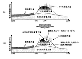
- FIGS. 1A and 1B are diagrams for explaining a charge / discharge method according to a mode of Example 1 of the present invention. It is a block diagram which shows the structure of the electric power control system which concerns on the form of Example 1 of this invention. It is a figure which shows an example of the table constructed
- the thermal storage type air conditioning system of Example 1 it is a figure for demonstrating the status when not using thermal storage energy.
- the thermal storage type air conditioning system of Example 1 it is a figure for demonstrating the status in thermal storage.
- thermal storage type air conditioning system of Example 1 it is a figure for demonstrating the status in the case of using thermal storage energy only about one system
- FIG. It is a figure for demonstrating the case where the flow control of cold water is performed in the thermal storage type
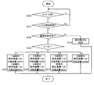
- FIG. It is a flowchart for demonstrating the thermal storage control by the control apparatus which concerns on embodiment of this invention of Example 1.
- FIG. It is a flowchart for demonstrating the 1st example of heat storage energy utilization control by the control apparatus which concerns on embodiment of this invention of Example 1.
- FIG. 14A and 14B are diagrams for explaining a charge / discharge method according to the first modification of the first embodiment. It is a figure which shows the modification of the heat storage type
- FIG. 16A and 16B are diagrams for explaining the charge / discharge method according to the mode of Example 2 of the present invention.
- Example 2 It is a block diagram which shows the structure of the electric power control system which concerns on the form of Example 2 of this invention.
- the thermal storage type air conditioning system of Example 2 it is a figure for demonstrating the status when not using thermal storage energy.
- the heat storage type showcase system of Example 2 it is a figure for demonstrating the status in heat storage.
- the heat storage type showcase system of Example 2 it is a figure for demonstrating the status in the case of using heat storage energy only about one system
- the heat storage type showcase system of Example 2 it is a figure for demonstrating the case where the flow control of a refrigerant
- the heat storage type showcase system of Example 2 it is a figure for demonstrating the case where the flow control of cold water is performed.
- FIG. 14A and 14B are diagrams for explaining a charge / discharge method according to the first modification of the second embodiment. It is a figure which shows the modification of the thermal storage type showcase system of Example 2.
- FIG. 14A and 14B are diagrams for explaining a charge / discharge method according to the first modification of the second embodiment. It is a figure which shows the modification of the thermal storage type showcase system of Example 2.
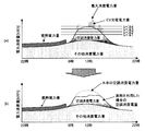
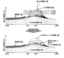
- FIGS. 1A and 1B are diagrams for explaining a charge / discharge method according to an embodiment of the present invention.
- the graph in FIG. 1A shows the transition of the daily power consumption of a certain facility.
- the power consumption of the facility is considered by dividing it into the power consumption of air conditioning, the amount of EV charging power, and the power consumption of other devices.
- the maximum peak power amount of the facility becomes larger than before the introduction.
- the conventional method of predicting the transition of the air conditioning load and using the heat storage energy cannot sufficiently suppress the maximum peak power amount of the facility.
- the graph of FIG.1 (b) shows transition of the said power consumption after applying the charging / discharging method which concerns on embodiment of this invention.
- the transition of the EV charging power amount is predicted, and the heat storage energy is used in a time zone when the EV charging power amount becomes large.
- the optimum amount of heat storage energy is used based on the predicted value of the EV charging power amount for each time zone. As a result, the maximum peak power of the store can be suppressed and the power consumption can be leveled.
- the EV charge energy is calculated as follows. Electric power required for EV quick charging is 20 kW when charging time is 30 minutes, 10 kW when charging for 1 hour, and 5 kW when charging for 2 hours.
- the maximum power consumption of an air conditioner is estimated as follows.
- the maximum power consumption of the air conditioner in summer is about 12 kWh when one system is composed of one outdoor unit and four indoor units. Therefore, the power consumption of the air conditioner is the number of systems ⁇ 12 kWh.
- the amount of electric power charged per EV is equivalent to one or two systems of air conditioners.
- the power consumption of air conditioners that can be reduced by using heat storage energy is about 15 to 20% of the original power consumption. In this case, assuming that the power consumption of the air conditioner is 100 kWh, using the heat storage energy, the power consumption is 80 kWh.
- heat storage energy By using heat storage energy, if the charging time is extended for about 2 EVs, the amount of charging power for about 4 EVs can be covered. Longer charging time will increase the number of EVs that can be covered.
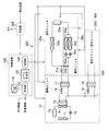
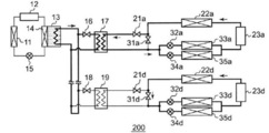
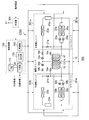
- FIG. 2 is a block diagram showing the configuration of the power control system 500 according to the embodiment of the present invention.
- the power control system 500 controls power to be supplied to equipment inside and outside the facility.
- the power control system 500 includes a control device 100, a regenerative air conditioning system 200, and a charger 300 for EV charging. Note that other power consuming devices installed in the facility (for example, lighting, showcases, etc.) are omitted.
- the control device 100 controls the regenerative air conditioning system 200.
- the control device 100 includes a database 110, a prediction unit 120, a level determination unit 130, and a control unit 140. These configurations can be realized by an arbitrary processor, memory, or other LSI in terms of hardware, and can be realized by a program loaded in the memory in terms of software, but here by their cooperation.
- Draw functional blocks Therefore, those skilled in the art will understand that these functional blocks can be realized in various forms by hardware only, software only, or a combination thereof.
- the database 110 holds historical data on the amount of EV charging power in the facility. For example, measurement data for the past several months is generated using, for example, a month (may be a season unit), a day of the week, a time zone, a weather condition, and an EV charging power amount as keys.
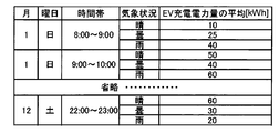
- FIG. 3 is a diagram illustrating an example of a table constructed in the database 110 according to the embodiment.
- the table includes, as items, a month, a day of the week, a time zone, a weather condition, and an average value of the EV charging electric energy (in FIG. 3, an average value for each hour).
- the month, the day of the week, and the time zone can be acquired from a date distribution server connected via a network (for example, the Internet).
- the weather situation can be acquired from a weather information distribution server connected via a network.
- the EV charging power amount can be acquired from the charger 300.
- temperature and humidity may be specified as weather conditions.
- the prediction unit 120 refers to the database 110 to predict the amount of charging power charged from the charger 300 to the EV. More specifically, the EV charging power amount for each month, day of the week, time zone, and weather condition corresponding to the forecast target date is acquired from the database 110, and the forecast for the forecast target date is acquired from the weather information distribution server. By doing this, the EV charging electric energy according to the time zone of the said prediction object day is estimated.
- the level determination unit 130 divides the predicted value of the EV charging power amount predicted by the prediction unit 120 into levels for each time zone.
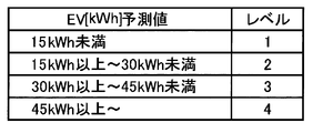
- FIG. 4 is a diagram illustrating an example of a table that defines the level division for using the heat storage energy according to the embodiment.
- the predicted value of the EV charging electric energy is set to level 1 when the value is less than 15 kWh
- level 2 is set to 15 kWh to less than 30 kWh
- level 3 is set to 30 kWh to less than 45 kWh
- level 4 is set to 45 kWh or more.
- the control unit 140 controls the heat storage and heat dissipation of the heat storage type air conditioning system 200 based on the prediction result by the prediction unit 120. More specifically, the control unit 140 increases the usage amount of the cold energy as the predicted power consumption amount is larger than that of other levels.
- the timing at which the heat storage energy can be used is the time zone when the air conditioner is on and other than during the heat storage. Usually, since heat storage is performed at midnight, it is a daytime (daytime) time zone.
- the thermal storage air conditioning system 200 includes a thermal storage unit 10, an outdoor unit 20, and an indoor unit 30.
- the outdoor unit 20 and the indoor unit 30 form one set, and these sets are hereinafter referred to as one system.
- an example in which the outdoor unit 20 and the indoor unit (two indoor units in the figure) 30 are installed in four systems will be described. That is, an example in which four systems of air conditioners are installed will be described.
- the number of air conditioners corresponds to the number of systems.
- the heat storage unit 10 includes a condenser 11, a compressor 12, a heat storage tank 13, an expansion valve 15, an on-off valve 16, a heat exchanger 17, an on-off valve 18, and a heat exchanger 19.
- the heat storage tank 13 includes an evaporator 14.
- a refrigerant circulation path is formed between the compressor 12, the condenser 11, the expansion valve 15, and the evaporator 14, and ice is made in the heat storage tank 13 by circulating the refrigerant through the path.
- a main chilled water circulation path is formed starting from the heat storage tank 13, and a sub chilled water circulation path passing through the heat exchanger 17 is connected to the path via an on-off valve 16.
- an on-off valve 16 By opening the on-off valve 16, cold water can flow through the cold water circulation path in the heat exchanger 17.
- the on-off valve 18 and the heat exchanger 19 have the same configuration as the on-off valve 16 and the heat exchanger 17.
- the outdoor unit 20a includes an on-off valve 21a, a condenser 22a, and a compressor 23a.
- the indoor unit 30a includes an on-off valve 31a, an expansion valve 32a, an evaporator 33a, an expansion valve 34a, and an evaporator 35a.
- the compressor 23a, the condenser 22a, the on-off valve 31a, the first path (series path of the expansion valve 32a and the evaporator 33a) and the second path (series path of the expansion valve 34a and the evaporator 35a) branched in parallel are annular.
- the main refrigerant circulation path connected to is formed.
- a sub refrigerant circulation path passing through the inside of the heat exchanger 17 is connected to the path through an on-off valve 21a. Heat storage energy can be acquired from the heat exchanger 17 by opening the on-off valve 21a.
- the other systems (only the outdoor unit 20d and the indoor unit 30d are illustrated in FIG. 2) have the same configuration.
- FIG. 5 is a diagram for explaining a status when heat storage energy is not used in the heat storage type air conditioning system 200.
- the on-off valve 21a is closed and the on-off valve 31a is opened. That is, the refrigerant circulates through the main refrigerant circulation path (see the thick line in FIG. 5), and energy is not supplied from the heat exchanger 17.
- the air conditioner operates only with electric power from the commercial power source.
- FIG. 6 is a diagram for explaining the status during heat storage in the heat storage type air conditioning system 200.
- the refrigerant circulates through the refrigerant circulation path (see the thick line in FIG. 6) in which the compressor 12, the condenser 11, the expansion valve 15, and the evaporator 14 are connected in an annular shape, and ice is formed in the heat storage tank 13.
- FIG. 7 is a diagram for explaining the status when the heat storage energy is used for only one system in the heat storage air conditioning system 200.
- the on-off valve 21a is opened and the on-off valve 31a is closed. That is, the compressor 23a, the condenser 22a, the on-off valve 21a, the heat exchanger 17, the first path (series path of the expansion valve 32a and the evaporator 33a) and the second path (expansion valve 34a and the evaporator) branched in parallel.
- a refrigerant circulation path in which the 35a series path) is connected in a ring shape is formed.
- energy is supplied from the heat exchanger 17.
- the on-off valve 21d is closed and the on-off valve 31d is opened. That is, the compressor 23d, the condenser 22d, the on-off valve 31d, the first path branched in parallel (series path of the expansion valve 32d and the evaporator 33d) and the second path (series path of the expansion valve 34d and the evaporator 35d).
- a refrigerant circulation path is formed in which are connected in a ring shape. In this system, energy is not replenished from the heat exchanger 19, and the air conditioner is operated only by electric power from the commercial power source.
- the control unit 140 can reduce the commercial power supplied to the regenerative air conditioning system 200 by increasing the number of systems that use the stored energy as the level determined by the level determining unit 130 is higher. .
- FIG. 8 is a diagram for explaining a case where the refrigerant flow rate control is performed in the regenerative air conditioning system 200.
- a pump 24a and an on-off valve 25a are further added to the outdoor unit 20a (see FIG. 2).
- the flow rate of the refrigerant passing through the heat exchanger 17 is controlled to be less than 100%.
- the flow rate of the refrigerant passing through the heat exchanger 19 is controlled to 100%.
- the on-off valve 21a and the on-off valve 25a are opened, and the on-off valve 31a is closed.
- the refrigerant flow path in which the series path of the vessel 35a is connected in an annular shape is formed, and the pumping capacity of the pump 24a is controlled to 50%, for example, so that the flow rate of the refrigerant passing through the heat exchanger 17 is controlled to 50%. Is done.
- the remaining 50% flow rate passes through the on-off valve 25a.
- the on-off valve 21d is opened, and the on-off valve 25d and the on-off valve 31d are closed.
- the refrigerant circulation path in which the series path of the vessel 35a is connected in an annular shape is formed, and the pumping capacity of the pump 24d is controlled to 100%, whereby the flow rate of the refrigerant passing through the heat exchanger 19 is controlled to 100%.
- the temperature of the refrigerant can be controlled by changing the refrigerant flow rate.
- the controller 140 can reduce the temperature of the refrigerant by changing the ratio of the amount of refrigerant circulating in the heat storage tank in the heat storage type air conditioning system 200 and the amount of refrigerant not circulating in the heat storage tank.
- the supplied commercial power can be reduced. That is, since part or all of the refrigerating capacity can be covered by the heat storage energy, power consumption can be reduced.
- the thick line in FIG. 8 indicates the chilled water circulation path in which the heat storage tank 13, the on-off valve 16, the heat exchanger 17, the on-off valve 18 and the heat exchanger 19 are connected in a ring shape, and the refrigerant circulation path of each system passing through each heat exchanger. Show. Note that the flow rate of the refrigerant passing through each heat exchanger is different.
- FIG. 9 is a diagram for explaining a case where the flow rate control of the cold water is performed in the regenerative air conditioning system 200.
- the heat storage unit 10 is provided with a pump 16 a instead of the on-off valve 16.
- the thick line in FIG. 9 indicates the chilled water circulation path in which the heat storage tank 13, the on-off valve 16, the heat exchanger 17, the on-off valve 18 and the heat exchanger 19 are connected in a ring shape, and the refrigerant circulation path of each system passing through each heat exchanger. Show. Note that the flow rate of cold water passing through each heat exchanger is different.
- the flow rate of the cold water passing through the heat exchanger 17 is controlled to 50% by controlling the pumping capacity of the pump 16a to 50%, for example.
- the flow rate of the cold water passing through the heat exchanger 19 is controlled to 100% by controlling the pumping capacity of the pump 18d to 100%.
- the control unit 140 can reduce the temperature of the refrigerant by changing the ratio of the flow rate of the cold water circulating to the heat storage tank in the heat storage air conditioning system 200 and the flow rate of the cold water not circulating to the heat storage tank.
- the commercial power supplied to 200 can be reduced. That is, since part or all of the refrigerating capacity can be covered by the heat storage energy, power consumption can be reduced.
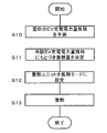
- FIG. 10 is a flowchart for explaining heat storage control by the control device 100 according to the embodiment of the present invention. This heat storage control is executed in a time zone (22:00 to 8:00) where the power consumption of the facility is small and the electricity bill is inexpensive.
- the prediction unit 120 predicts the transition of the EV charging power amount on the next day using the method described above (S10).
- the control unit 140 determines the amount of heat stored in the heat storage tank based on the transition of the EV charging power amount (S11).
- the controller 140 sets the configuration of the heat storage unit as shown in FIG. 6 (S12).
- the heat storage unit starts heat storage (S13). That is, ice making to the heat storage tank is started.
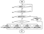
- FIG. 11 is a flowchart for explaining a first example of heat storage energy use control by the control device 100 according to the embodiment of the present invention.
- This heat storage energy use control is executed in the time zone from 8:00 to 22:00.
- the heat storage energy utilization control according to the first example is executed by controlling the number of systems. As described above, four systems are assumed in the present embodiment.
- the control unit 140 determines whether or not the heat storage energy can be used ( S22). When it cannot be used (for example, when the stored energy is used up) (N in S22), the air conditioner is operated using commercial power (S23).
- the control unit 140 confirms the above level (see FIG. 4 above) (S24).
- level 1 one of the four systems is operated using heat storage energy (S25).
- level 2 two of the four systems are operated using heat storage energy (S26). Of these, three systems are operated using heat storage energy (S27), and in the case of level 4, all four systems are operated using heat storage energy (S28). Systems that do not operate using heat storage energy are operated by commercial power.
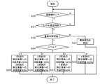
- FIG. 12 is a flowchart for explaining a second example of heat storage energy use control by the control device 100 according to the embodiment of the present invention.
- the heat storage energy use control according to the second example is executed by refrigerant flow rate control.
- Steps S30 to S33 in the flowchart according to the second example are the same as steps S20 to S23 in the flowchart according to the first example, and thus description thereof is omitted.
- the control unit 140 confirms the above level (S34).
- level 1 the refrigerant flow rate to one heat exchanger among the four systems is set to 100%, and the refrigerant flow rate to the three heat exchangers is set to 50% (S35).
- level 2 the refrigerant flow rate to the two heat exchangers out of the four lines is set to 100%, and the refrigerant flow rate to the two heat exchangers is set to 50% (S36).
- the refrigerant flow rate to the three heat exchangers of the four systems is set to 100%, and the refrigerant flow rate to the one system heat exchanger is set to 50% (S37).
- level 4 the refrigerant flow rates to all four heat exchangers are set to 100% (S38).
- the EV charge power amount is predicted, and the energy stored in the heat storage air-conditioning system is used in the time zone when the EV charge power amount increases, so that The peak power consumption can be suppressed and the power consumption of the facility can be leveled. Further, by storing heat at night when the power rate is low and using the stored energy during EV charging in the daytime, the total electricity rate can be reduced.
- the level determination unit 130 performs the level division based on the predicted value of the amount of electric power charged to the EV.
- the level determination unit 130 includes the maximum power consumption amount of the facility per unit time, the predicted value of the electric energy charged to the EV per unit time, the predicted value of the power consumption amount of the regenerative air conditioning system 200, and the facility.
- the ratio of the predicted value of the power consumption of other devices to the total power consumption is divided into levels.
- a weighting factor based on the outside air temperature or COP (Coefficient Of Performance) may be applied to the predicted value of the EV charging electric energy.
- the predicted value of the power consumption amount of the heat storage type air conditioning system 200 and the predicted value of the power consumption amount of other devices are also generated by constructing a measurement data table in the same manner as the EV charging power amount shown in FIG. Is possible.
- FIG. 13 is a diagram showing a table that defines the level division for using the heat storage energy according to the first modification.
- the predicted power consumption per hour [kWh / h] predicted value of EV charging power per hour + heat storage per hour relative to the maximum power consumption [kWh / h] in the facility per hour
- the level is divided according to the ratio of the predicted value of the power consumption of the air conditioning system 200 + the predicted value of the power consumption of other devices).
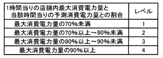
- the ratio is less than 70%, it is set as level 1, 70% or more to less than 80% as level 2, 80% or more to less than 90% as level 3, and 90% or more as level 4.
- FIGS. 14A and 14B are diagrams for explaining the charge / discharge method according to the first modification.
- the graph of FIG. 14A shows a level division line for the maximum power consumption in the facility.
- the graph of FIG.14 (b) has shown the example when the control part 140 utilizes the thermal storage energy according to the said level for every time slot
- FIG. 14A shows a level division line for the maximum power consumption in the facility.
- the graph of FIG.14 (b) has shown the example when the control part 140 utilizes the thermal storage energy according to the said level for every time slot
- the heat storage air conditioning system 200 can be controlled based on more detailed prediction, the maximum peak power amount of the facility can be suppressed with higher accuracy.
- the level determining unit 130 calculates the total power consumption of the maximum power consumption of the facility per unit time, the predicted value of the charged power amount to the EV per unit time, and the predicted value of the power consumption amount of the heat storage air conditioning system 200.
- the ratio of the quantity may be divided into levels. In this case, the accuracy of suppressing the maximum peak power amount is lower than that of the first modification, but it is not necessary to collect the measurement data of the power consumption amount of the other devices, so that the configuration can be simplified. .
- the heat storage tank 13 includes an evaporator 14, a heat exchanger 17, and a heat exchanger 19.
- a refrigerant circulation path in which the compressor 23 a, the condenser 22 a, the on-off valve 16 b, the expansion valve 15 a and the evaporator 14 are connected in an annular shape is formed, and ice is made in the heat storage tank 13.
- ice may be made in the heat storage tank 13 by a refrigerant circulation path in which the compressor 23b, the condenser 22b, the on-off valve 18b, the expansion valve 15b, and the evaporator 14 are connected on the ring.
- the configuration of the heat storage unit 10 can be simplified by sharing the heat exchanger among a plurality of systems.
- FIGS. 16A and 16B are diagrams for explaining the charge / discharge method according to the embodiment of the present invention.
- the graph of FIG. 16A shows the transition of the daily power consumption of a certain facility.
- the power consumption of the facility is considered by dividing it into the power consumption of the showcase, the EV charging power, and the power consumption of other devices.
- the maximum peak power amount of the facility becomes larger than before the introduction.
- the conventional method of predicting the transition of the air conditioning load and using the heat storage energy cannot sufficiently suppress the maximum peak power amount of the facility.
- the graph of FIG.16 (b) shows transition of the said electric power consumption after applying the charging / discharging method which concerns on embodiment of this invention.
- the transition of the EV charging power amount is predicted, and the heat storage energy is used in a time zone when the EV charging power amount becomes large.
- the optimum amount of heat storage energy is used based on the predicted value of the EV charging power amount for each time zone. As a result, the maximum peak power of the store can be suppressed and the power consumption can be leveled.
- the EV charge energy is calculated as follows. Electric power required for EV quick charging is 20 kW when charging time is 30 minutes, 10 kW when charging for 1 hour, and 5 kW when charging for 2 hours.
- the maximum power consumption of the showcase is calculated as follows.
- the maximum power consumption of the showcase in summer is about 12 kWh when one system is composed of one refrigerator and four showcases. Therefore, the power consumption of the showcase is the number of systems ⁇ 12 kWh.
- the charge energy of one EV corresponds to one or two showcases.
- the power consumption of the showcase that can be reduced using heat storage energy is about 15-20% of the original power consumption. In this case, assuming that the power consumption of the showcase is 100 kWh, using the heat storage energy, the power consumption is 80 kWh.
- the charging time is extended for about 2 EVs, the amount of charging power for about 4 EVs can be covered. Longer charging time will increase the number of EVs that can be covered.
- FIG. 17 is a block diagram showing a configuration of a power control system 500 according to the embodiment of the present invention.
- the power control system 500 controls power to be supplied to equipment inside and outside the facility.
- the power control system 500 includes a control device 100, a heat storage type showcase system 1200, and a charger 300 for EV charging. Note that other power consuming devices (for example, lighting, air conditioning, etc.) installed in the facility are omitted.
- the control device 100 controls the heat storage type showcase system 1200.
- the control device 100 includes a database 110, a prediction unit 120, a level determination unit 130, and a control unit 140. These configurations can be realized by an arbitrary processor, memory, or other LSI in terms of hardware, and can be realized by a program loaded in the memory in terms of software, but here by their cooperation.
- Draw functional blocks Therefore, those skilled in the art will understand that these functional blocks can be realized in various forms by hardware only, software only, or a combination thereof.
- the database 110 holds historical data on the amount of EV charging power in the facility. For example, measurement data for the past several months is generated using, for example, a month (may be a season unit), a day of the week, a time zone, a weather condition, and an EV charging power amount as keys.
- FIG. 3 is a diagram illustrating an example of a table constructed in the database 110 according to the embodiment.
- the table includes items such as a month, a day of the week, a time zone, a weather condition, and an average value of the EV charging electric energy (an average value every hour in FIG. 3).
- the month, the day of the week, and the time zone can be acquired from a date distribution server connected via a network (for example, the Internet).
- the weather situation can be acquired from a weather information distribution server connected via a network.
- the EV charging power amount can be acquired from the charger 300.
- temperature and humidity may be specified as weather conditions.
- the prediction unit 120 refers to the database 110 to predict the amount of charging power charged from the charger 300 to the EV. More specifically, the EV charging power amount for each month, day of the week, time zone, and weather condition corresponding to the forecast target date is acquired from the database 110, and the forecast for the forecast target date is acquired from the weather information distribution server. By doing this, the EV charging electric energy according to the time zone of the said prediction object day is estimated.
- the level determination unit 130 divides the predicted value of the EV charging power amount predicted by the prediction unit 120 into levels for each time zone.
- FIG. 4 is a diagram illustrating an example of a table that defines the level division for using the heat storage energy according to the embodiment.
- the predicted value of the EV charging electric energy is set to level 1 when the value is less than 15 kWh
- level 2 is set to 15 kWh to less than 30 kWh
- level 3 is set to 30 kWh to less than 45 kWh
- level 4 is set to 45 kWh or more.
- the control unit 140 controls heat storage and heat dissipation of the heat storage type showcase system 1200 based on the prediction result by the prediction unit 120. More specifically, the control unit 140 increases the usage amount of the cold energy as the predicted power consumption amount is larger than that of other levels.
- the timing at which the heat storage energy can be used is a time zone other than during the heat storage when the showcase is on. Usually, since heat storage is performed at midnight, it is a daytime (daytime) time zone.
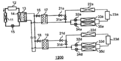
- the heat storage type showcase system 1200 includes a heat storage unit 10, a refrigerator unit 201, and a showcase unit 301.
- the refrigerator unit 201 and the showcase unit 301 form one set, and these sets are hereinafter referred to as one system.
- an example in which the refrigerator unit 201 and the showcase unit (two showcases in the figure) 301 are installed in four systems will be described. That is, an example in which four showcases are installed will be described.
- the number of showcases corresponds to the number of systems.
- the heat storage unit 10 includes a condenser 11, a compressor 12, a heat storage tank 13, an expansion valve 15, an on-off valve 16, a heat exchanger 17, an on-off valve 18, and a heat exchanger 19.
- the heat storage tank 13 includes an evaporator 14.
- a refrigerant circulation path is formed between the compressor 12, the condenser 11, the expansion valve 15, and the evaporator 14, and ice is made in the heat storage tank 13 by circulating the refrigerant through the path.
- a main chilled water circulation path is formed starting from the heat storage tank 13, and a sub chilled water circulation path passing through the heat exchanger 17 is connected to the path via an on-off valve 16.
- an on-off valve 16 By opening the on-off valve 16, cold water can flow through the cold water circulation path in the heat exchanger 17.
- the on-off valve 18 and the heat exchanger 19 have the same configuration as the on-off valve 16 and the heat exchanger 17.
- the refrigerator unit 201a includes an on-off valve 21a, a condenser 22a, and a compressor 23a.
- the showcase unit 301a includes an on-off valve 31a, an expansion valve 32a, an evaporator 33a, an expansion valve 34a, and an evaporator 35a.
- the compressor 23a, the condenser 22a, the on-off valve 31a, the first path (series path of the expansion valve 32a and the evaporator 33a) and the second path (series path of the expansion valve 34a and the evaporator 35a) branched in parallel are annular.
- the main refrigerant circulation path connected to is formed.
- a sub refrigerant circulation path passing through the inside of the heat exchanger 17 is connected to the path through an on-off valve 21a. Heat storage energy can be acquired from the heat exchanger 17 by opening the on-off valve 21a.
- the other systems in FIG. 17, only the refrigerator unit 201d and the showcase unit 301d are illustrated) have the same configuration.
- FIG. 18 is a diagram for explaining a status when heat storage energy is not used in the heat storage type showcase system 1200.
- the on-off valve 21a is closed and the on-off valve 31a is opened. That is, the refrigerant circulates through the main refrigerant circulation path (see the thick line in FIG. 18), and energy is not supplied from the heat exchanger 17.
- the showcase is operated only by power from the commercial power source.
- FIG. 19 is a diagram for explaining the status during heat storage in the heat storage type showcase system 1200.
- the refrigerant circulates through the refrigerant circulation path (see the thick line in FIG. 19) in which the compressor 12, the condenser 11, the expansion valve 15 and the evaporator 14 are connected in an annular shape, and ice is formed in the heat storage tank 13.
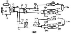
- FIG. 20 is a diagram for explaining a status when the heat storage energy is used for only one system in the heat storage type showcase system 1200.
- the on-off valve 21a is opened and the on-off valve 31a is closed. That is, the compressor 23a, the condenser 22a, the on-off valve 21a, the heat exchanger 17, the first path (series path of the expansion valve 32a and the evaporator 33a) and the second path (expansion valve 34a and the evaporator) branched in parallel.
- a refrigerant circulation path in which the 35a series path) is connected in a ring shape is formed.
- energy is supplied from the heat exchanger 17.
- the on-off valve 21d is closed and the on-off valve 31d is opened. That is, the compressor 23d, the condenser 22d, the on-off valve 31d, the first path branched in parallel (series path of the expansion valve 32d and the evaporator 33d) and the second path (series path of the expansion valve 34d and the evaporator 35d).
- a refrigerant circulation path is formed in which are connected in a ring shape. In this system, energy is not replenished from the heat exchanger 19, and the air conditioner is operated only by electric power from the commercial power source.
- the control unit 140 may reduce the commercial power supplied to the regenerative showcase system 1200 by increasing the number of systems using the stored energy as the level determined by the level determining unit 130 is higher. it can.
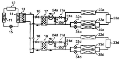
- FIG. 21 is a diagram for explaining a case where the refrigerant flow rate control is performed in the heat storage type showcase system 1200.
- a pump 24a and an on-off valve 25a are further added to the refrigerator unit 201a (see FIG. 17).
- the flow rate of the refrigerant passing through the heat exchanger 17 is controlled to be less than 100%.
- the flow rate of the refrigerant passing through the heat exchanger 19 is controlled to 100%.
- the on-off valve 21a and the on-off valve 25a are opened, and the on-off valve 31a is closed.
- the refrigerant flow path in which the series path of the vessel 35a is connected in an annular shape is formed, and the pumping capacity of the pump 24a is controlled to 50%, for example, so that the flow rate of the refrigerant passing through the heat exchanger 17 is controlled to 50%. Is done.
- the remaining 50% flow rate passes through the on-off valve 25a.
- the on-off valve 21d is opened, and the on-off valve 25d and the on-off valve 31d are closed.
- the refrigerant circulation path in which the series path of the vessel 35a is connected in an annular shape is formed, and the pumping capacity of the pump 24d is controlled to 100%, whereby the flow rate of the refrigerant passing through the heat exchanger 19 is controlled to 100%.
- the temperature of the refrigerant can be controlled by changing the refrigerant flow rate.
- the controller 140 can reduce the temperature of the refrigerant by changing the ratio of the amount of refrigerant circulating to the heat storage tank in the heat storage type showcase system 1200 and the amount of refrigerant not circulating to the heat storage tank, and the heat storage type showcase system Commercial power supplied to 1200 can be reduced. That is, since part or all of the refrigerating capacity can be covered by the heat storage energy, power consumption can be reduced.
- 21 indicates a chilled water circulation path in which the heat storage tank 13, the on-off valve 16, the heat exchanger 17, the on-off valve 18 and the heat exchanger 19 are connected in a ring shape, and a refrigerant circulation path of each system passing through each heat exchanger. Show. Note that the flow rate of the refrigerant passing through each heat exchanger is different.
- FIG. 22 is a diagram for explaining a case where the flow rate control of the cold water is performed in the heat storage type showcase system 1200.
- the heat storage unit 10 is provided with a pump 16 a instead of the on-off valve 16.
- the thick line in FIG. 22 indicates the chilled water circulation path in which the heat storage tank 13, the on-off valve 16, the heat exchanger 17, the on-off valve 18 and the heat exchanger 19 are connected in a ring shape, and the refrigerant circulation path of each system passing through each heat exchanger. Show. Note that the flow rate of cold water passing through each heat exchanger is different.
- the flow rate of the cold water passing through the heat exchanger 17 is controlled to 50% by controlling the pumping capacity of the pump 16a to 50%, for example.
- the flow rate of the cold water passing through the heat exchanger 19 is controlled to 100% by controlling the pumping capacity of the pump 18d to 100%.
- the controller 140 can reduce the temperature of the refrigerant by changing the ratio of the flow rate of cold water circulating to the heat storage tank in the heat storage type showcase system 1200 and the flow rate of cold water not circulating to the heat storage tank.
- Commercial power supplied to the case system 1200 can be reduced. That is, since part or all of the refrigerating capacity can be covered by the heat storage energy, power consumption can be reduced.
- FIG. 10 is a flowchart for explaining heat storage control by the control device 100 according to the embodiment of the present invention. This heat storage control is executed in a time zone (22:00 to 8:00) where the power consumption of the facility is small and the electricity bill is inexpensive.
- the prediction unit 120 predicts the transition of the EV charging power amount on the next day using the method described above (S10).
- the control unit 140 determines the amount of heat stored in the heat storage tank based on the transition of the EV charging power amount (S11).
- the controller 140 sets the configuration of the heat storage unit as shown in FIG. 19 (S12).
- the heat storage unit starts heat storage (S13). That is, ice making to the heat storage tank is started.
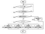
- FIG. 23 is a flowchart for explaining a first example of heat storage energy use control by the control device 100 according to the embodiment of the present invention.
- This heat storage energy use control is executed in the time zone from 8:00 to 22:00.
- the heat storage energy utilization control according to the first example is executed by controlling the number of systems. As described above, four systems are assumed in the present embodiment.
- the control unit 140 determines whether or not the heat storage energy can be used ( S22). When it cannot be used (for example, when the stored energy is used up) (N in S22), the showcase is operated using commercial power (S23).
- the control unit 140 confirms the above level (see FIG. 4 above) (S24).
- level 1 one of the four systems is operated using heat storage energy (S25).
- level 2 two of the four systems are operated using heat storage energy (S26). Of these, three systems are operated using heat storage energy (S27), and in the case of level 4, all four systems are operated using heat storage energy (S28). Systems that do not operate using heat storage energy are operated by commercial power.
- FIG. 24 is a flowchart for explaining a second example of heat storage energy use control by the control device 100 according to the embodiment of the present invention.
- the heat storage energy use control according to the second example is executed by refrigerant flow rate control.
- Steps S30 to S33 in the flowchart according to the second example are the same as steps S20 to S23 in the flowchart according to the first example, and thus description thereof is omitted.
- the control unit 140 confirms the above level (S34).
- level 1 the refrigerant flow rate to one heat exchanger among the four systems is set to 100%, and the refrigerant flow rate to the three heat exchangers is set to 50% (S35).
- level 2 the refrigerant flow rate to the two heat exchangers out of the four lines is set to 100%, and the refrigerant flow rate to the two heat exchangers is set to 50% (S36).
- the refrigerant flow rate to the three heat exchangers of the four systems is set to 100%, and the refrigerant flow rate to the one system heat exchanger is set to 50% (S37).
- level 4 the refrigerant flow rates to all four heat exchangers are set to 100% (S38).
- the EV charge power amount is predicted, and the energy stored in the heat storage type showcase system is used during the time period when the EV charge power amount increases,
- the maximum peak power consumption can be suppressed and the power consumption of the facility can be leveled.
- the total electricity rate can be reduced.
- the level determination unit 130 performs the level division based on the predicted value of the amount of electric power charged to the EV.
- the level determination unit 130 includes a maximum power consumption amount of the facility per unit time, a predicted value of the charged power amount to the EV per unit time, a predicted value of the power consumption amount of the heat storage type showcase system 1200, and The ratio of the predicted value of the power consumption of other equipment in the facility to the total power consumption is divided into levels.
- a weighting coefficient based on the outside air temperature or COP (Coefficient Of Performance) may be applied to the predicted value of the EV charging electric energy.
- the predicted value of the power consumption amount of the heat storage type showcase system 1200 and the predicted value of the power consumption amount of other devices are also constructed by building a measurement data table in the same manner as the EV charging power amount shown in FIG. Can be generated.
- FIG. 13 is a diagram showing a table that defines the level division for using the heat storage energy according to the first modification.
- the predicted power consumption per hour [kWh / h] predicted value of EV charging power per hour + heat storage per hour relative to the maximum power consumption [kWh / h] in the facility per hour
- the level is divided according to the ratio of the predicted value of the power consumption of the formula showcase system 1200 + the predicted value of the power consumption of other devices.
- the ratio is less than 70%, it is set as level 1, 70% or more to less than 80% as level 2, 80% or more to less than 90% as level 3, and 90% or more as level 4.
- FIGS. 25A and 25B are diagrams for explaining the charge / discharge method according to the first modification.
- the graph in FIG. 25A shows level division lines for the maximum power consumption in the facility.
- the graph of FIG. 25B illustrates an example in which the control unit 140 controls the power consumption of the heat storage type showcase system 1200 using the heat storage energy according to the above level for each time zone.
- the heat storage type showcase system 1200 can be controlled based on more detailed prediction, the maximum peak power amount of the facility can be suppressed with higher accuracy.
- the level determining unit 130 calculates the total consumption of the maximum power consumption of the facility per unit time, the predicted value of the charged power amount to the EV per unit time, and the predicted value of the power consumption of the heat storage type showcase system 1200.
- the ratio of the amount of power may be divided into levels. In this case, the accuracy of suppressing the maximum peak power amount is lower than that of the first modification, but it is not necessary to collect the measurement data of the power consumption amount of the other devices, so that the configuration can be simplified. .
- the heat storage tank 13 includes an evaporator 14, a heat exchanger 17, and a heat exchanger 19.
- a refrigerant circulation path in which the compressor 23 a, the condenser 22 a, the on-off valve 16 b, the expansion valve 15 a and the evaporator 14 are connected in an annular shape is formed, and ice is made in the heat storage tank 13.
- ice may be made in the heat storage tank 13 by a refrigerant circulation path in which the compressor 23b, the condenser 22b, the on-off valve 18b, the expansion valve 15b, and the evaporator 14 are connected on the ring.
- the configuration of the heat storage unit 10 can be simplified by sharing the heat exchanger among a plurality of systems.
- the power control system 500 is applied to a facility such as a store has been described.
- the power control system 500 can also be applied to each home.
- Example 3 The present invention can also be applied to the case where a regenerative air conditioning system and a regenerative showcase system are installed in a store.
- the fluctuation of the air conditioning power consumption is larger than the fluctuation of the showcase power consumption. Therefore, in the heat storage type air conditioning system, the air conditioning power consumption is predicted from the outside air temperature, etc., and the air conditioning power consumption is controlled by performing the level classification as shown in FIG. Reduce the peak power consumption.
- the amount of heat stored in the heat storage type showcase system is confirmed, and when the heat storage is available, the energy stored in the heat storage type showcase system can be used for EV charging.
- the heat storage energy in the heat storage type air conditioning system is used for EV charging along FIG. 4 or for the entire store along FIG.
- the power control system 500 is applied to a facility such as a store has been described.
- the power control system 500 can also be applied to each home.
- control device 110 database, 120 prediction unit, 130 level determination unit, 140 control unit, 200 heat storage air conditioning system, 300 charger, 500 power control system, 1200 heat storage showcase system
Landscapes
- Engineering & Computer Science (AREA)
- Mechanical Engineering (AREA)
- Physics & Mathematics (AREA)
- Thermal Sciences (AREA)
- Life Sciences & Earth Sciences (AREA)
- Sustainable Development (AREA)
- Sustainable Energy (AREA)
- Chemical & Material Sciences (AREA)
- Combustion & Propulsion (AREA)
- General Engineering & Computer Science (AREA)
- Air Conditioning Control Device (AREA)
Abstract
【課題】施設の最大ピーク電力量を抑制する。 【解決手段】電気自動車への充電用の充電器300が設置された施設における蓄熱式空調システム200の制御装置100において、予測部120は、電気自動車への充電電力量を予測する。制御部140は、予測部120による予測結果にもとづいて、蓄熱式空調システム200の蓄熱および放熱を制御する。制御部140は、電気自動車への充電電力量の予測値の、時間帯ごとのレベル分けに応じて、蓄熱式空調システム200内に蓄熱されたエネルギーの使用量を決定してもよい。
Description
本発明は、電気自動車への充電用の充電器が設置された施設における蓄熱式空調システムおよび蓄熱式ショーケースシステムの制御装置に関する。
ショッピングセンターやコンビニエンスストアなどの店舗の電気料金は、最大ピーク電力量の大きさにより決定される契約形態が一般的である。よって、最大ピーク電力量を極力小さくすることが望まれる。そのため、蓄熱式空調システムを導入し、夜間に蓄熱したエネルギーを、空調負荷が大きい昼間に利用することにより、ピーク電力量の大きさを低減する仕組みが普及している。それに関連して、翌日の空調負荷を予測して夜間に蓄熱するエネルギー量を決定したり、空調負荷の予測値と現在の蓄熱残量との差に応じて、圧縮機の運転能力を決定する手法などが提案されている(たとえば、特許文献1、2参照)。
ところで近年、電気自動車(以下適宜、EVと表記する)が普及しはじめており、ショッピングセンターやコンビニエンスストアなどの店舗にも、充電設備が設置されることが予想される。今後、店舗への来客者がEV充電設備を使用することにより、その店舗のEV充電時間帯の消費電力量が大きくなると予測される。なお、本明細書においてEVに充電される電力とは、主にEVを駆動するための電力を指し、主に車両内の電子機器に供給される既存の自動車に搭載されるバッテリに充電される電力ではない。
蓄熱式空調システムや蓄熱式ショーケースシステムにおいて、蓄熱されたエネルギーは空調負荷、ショーケース負荷が大きいときに多く利用することが望ましいため、空調負荷、ショーケース負荷の推移を予測して、その放熱スケジュールを決定している。今後、EV充電設備が導入されると、外気温度に影響される空調負荷の変動とは全く異なるEV充電量の変動も考慮する必要が出てくる。
例えば空調負荷は外気温度により影響されるため、外気温度が高くなると負荷も高くなり、消費電力量も高くなる。それに対し、EV充電量は外気温度と関係なく、来客数に影響されると考えられる。
EV充電設備導入後において、従来の空調負荷のみの予測制御では、EV充電電力量により、契約電力ピーク量を超えてしまう可能性がある。また、EV充電による急峻な消費電力量増加が発生することにより、消費電力量の平準化が難しくなる。
また、消費電力量の時々刻々の変化に対して空調システムを、予測制御ではなく、適応制御した場合、蓄熱エネルギー利用の効果が空調機に現れるまでに時間がかかる。また、蓄熱エネルギーを使い切ってしまった後は、対応することができない。
本発明はこうした状況に鑑みなされたものであり、その目的は、施設の最大ピーク電力量を抑制する技術を提供することにある。
本発明のある態様の蓄熱式空調システムの制御装置は、電気自動車への充電用の充電器が設置された施設における蓄熱式空調システムの制御装置であって、電気自動車への充電電力量を予測する予測部と、予測部による予測結果にもとづいて、蓄熱式空調システムの蓄熱および放熱を制御する制御部と、を備える。
また、本発明のある態様の蓄熱式ショーケースシステムの制御装置は、電気自動車への充電用の充電器が設置された施設における蓄熱式ショーケースシステムの制御装置であって、電気自動車への充電電力量を予測する予測部と、予測部による予測結果にもとづいて、蓄熱式ショーケースシステムの蓄熱および放熱を制御する制御部と、を備える。
なお、以上の構成要素の任意の組み合わせ、本発明の表現を方法、装置、システム、記録媒体、コンピュータプログラム等の間で変換したものもまた、本発明の態様として有効である。
本発明によれば、施設の最大ピーク電力を抑制することができる。
(実施例1)
まず、本発明の実施の形態を詳細に説明する前に、本発明の実施の形態の概要を述べる。図1(a)、(b)は、本発明の実施の形態に係る充放電方法を説明するための図である。図1(a)のグラフは、ある施設の一日の消費電力量の推移を示す。以下本明細書では、このグラフに示すように、施設の消費電力量を空調消費電力量、EV充電電力量およびその他の機器の消費電力量に分けて考える。EV充電設備が導入されると導入前と比べて、施設の最大ピーク電力量が大きくなる。このグラフに示すように、従来通りに、空調負荷の推移を予測して、蓄熱エネルギーを利用する手法では施設の最大ピーク電力量を十分に抑えることができない。
まず、本発明の実施の形態を詳細に説明する前に、本発明の実施の形態の概要を述べる。図1(a)、(b)は、本発明の実施の形態に係る充放電方法を説明するための図である。図1(a)のグラフは、ある施設の一日の消費電力量の推移を示す。以下本明細書では、このグラフに示すように、施設の消費電力量を空調消費電力量、EV充電電力量およびその他の機器の消費電力量に分けて考える。EV充電設備が導入されると導入前と比べて、施設の最大ピーク電力量が大きくなる。このグラフに示すように、従来通りに、空調負荷の推移を予測して、蓄熱エネルギーを利用する手法では施設の最大ピーク電力量を十分に抑えることができない。
図1(b)のグラフは、本発明の実施の形態に係る充放電方法を適用した後の、上記消費電力量の推移を示す。当該充放電方法では、EV充電電力量の推移を予測し、EV充電電力量が大きくなる時間帯に蓄熱エネルギーを使用する。その際、EV充電電力量の時間帯ごとの予測値にもとづいて、最適な量の蓄熱エネルギーを利用する。これにより、店舗の最大ピーク電力を抑え、消費電力量を平準化することができる。
一例として、EV充電電力量を次のように試算する。EVの急速充電に必要な電力は充電時間30分かけると20kW、1時間かけると10kW、2時間かけると5kWになる。
一例として、空調機の最大消費電力量を次のように試算する。夏期における空調機の最大消費電力量は、一系統が室外機一台と室内機四台で構成される場合、約12kWhである。したがって、空調機の消費電力量は、系統数×12kWhとなる。
EV一台の充電電力量は、空調機の一系統~二系統弱にあたる。蓄熱エネルギーを利用して削減できる空調機の消費電力量は、もともとの消費電力量の約15~20%である。この場合、空調機の消費電力量が100kWhとすると、蓄熱エネルギーを利用すると、その消費電力量は80kWhになる。蓄熱エネルギー利用により、EV約2台分、充電時間を長くすると約4台分の充電電力量をまかなうことができる。充電時間を長くとると、まかなえるEVの台数は増える。
図2は、本発明の実施の形態に係る電力制御システム500の構成を示すブロック図である。電力制御システム500は、施設内外の機器に供給されるべき電力を制御する。電力制御システム500は、制御装置100、蓄熱式空調システム200およびEV充電用の充電器300を備える。なお、施設に設置されるその他の電力消費機器(たとえば、照明、ショーケースなど)については省略して描いている。
制御装置100は、蓄熱式空調システム200を制御する。制御装置100は、データベース110、予測部120、レベル決定部130および制御部140を備える。これらの構成は、ハードウェア的には、任意のプロセッサ、メモリ、その他のLSIで実現でき、ソフトウェア的にはメモリにロードされたプログラムなどによって実現されるが、ここではそれらの連携によって実現される機能ブロックを描いている。したがって、これらの機能ブロックがハードウェアのみ、ソフトウェアのみ、またはそれらの組み合わせによっていろいろな形で実現できることは、当業者には理解されるところである。
データベース110は、当該施設におけるEV充電電力量のヒストリカルデータを保持する。たとえば、過去数カ月間の計測データを、たとえば、月(季節単位であってもよい)、曜日、時間帯、気象状況およびEV充電電力量をキーとして計測データを生成する。
図3は、実施の形態に係るデータベース110に構築されるテーブルの一例を示す図である。当該テーブルは、項目として、月、曜日、時間帯、気象状況およびEV充電電力量の平均値(図3では、一時間ごとの平均値)を含む。このうち、月、曜日および時間帯は、ネットワーク(たとえば、インターネット)を介して接続された日付配信サーバから取得することができる。気象状況は、ネットワークを介して接続された気象情報配信サーバから取得することができる。EV充電電力量は、充電器300から取得することができる。
なお、テーブルの項目はより細かく規定されてもよく、たとえば気象状況として気温や湿度などが規定されてもよい。
図2に戻り、予測部120はデータベース110を参照して、充電器300からEVに充電される充電電力量を予測する。より具体的には、予想対象日に該当する月、曜日、時間帯、気象状況別のEV充電電力量をデータベース110から取得し、かつ当該予想対象日の気象予報を上記気象情報配信サーバから取得することにより、当該予想対象日の時間帯別のEV充電電力量を予測する。
レベル決定部130は、予測部120により予測されたEV充電電力量の予測値を、時間帯ごとにレベル分けする。
図4は、実施の形態に係る蓄熱エネルギーを利用するためのレベル分けを規定したテーブルの一例を示す図である。当該テーブルでは、EV充電電力量の予測値が15kWh未満をレベル1、15kWh以上~30kWh未満をレベル2、30kWh以上~45kWh未満をレベル3、および45kWh以上をレベル4としている。
図2に戻り、制御部140は予測部120による予測結果にもとづいて、蓄熱式空調システム200の蓄熱および放熱を制御する。より具体的には、制御部140は、他のレベルと比較して予測消費電力量が大きいレベルほど、冷熱のエネルギーの使用量を多くする。なお、蓄熱式空調システム200では、蓄熱エネルギーが利用できるタイミングは、空調機がオンの状態であり、蓄熱中以外の時間帯である。通常、蓄熱は深夜に行われるため、日中(昼間)の時間帯である。
蓄熱式空調システム200は、蓄熱ユニット10、室外ユニット20および室内ユニット30を備える。ここで、室外ユニット20および室内ユニット30は一つの組をなし、以下、それら一組を一系統と呼ぶ。また、本実施の形態では室外ユニット20および室内ユニット(図では室内機が2台)30が四系統設置される例を説明する。すなわち、空調機が四系統設置される例を説明する。このように、空調機の数と系統数は対応する。
蓄熱ユニット10は、凝縮器11、圧縮器12、蓄熱槽13、膨張弁15、開閉弁16、熱交換器17、開閉弁18および熱交換器19を備える。蓄熱槽13は蒸発器14を含む。圧縮器12、凝縮器11、膨張弁15および蒸発器14の間に冷媒循環経路が形成され、その経路を冷媒が循環することにより、蓄熱槽13に氷が作られる。
蓄熱槽13を起点にメインの冷水循環経路が形成されており、その経路に開閉弁16を介して、熱交換器17内を通るサブの冷水循環経路が接続されている。開閉弁16を開くことにより、熱交換器17内の冷水循環経路に冷水を流すことができる。開閉弁18および熱交換器19も、開閉弁16および熱交換器17と同様の構成である。
室外ユニット20aは、開閉弁21a、凝縮器22aおよび圧縮器23aを備える。室内ユニット30aは、開閉弁31a、膨張弁32a、蒸発器33a、膨張弁34aおよび蒸発器35aを備える。
圧縮器23a、凝縮器22a、開閉弁31a、並列に分岐された第1経路(膨張弁32aおよび蒸発器33aの直列経路)および第2経路(膨張弁34aおよび蒸発器35aの直列経路)が環状に繋がったメインの冷媒循環経路が形成される。その経路に開閉弁21aを介して、熱交換器17内を通るサブの冷媒循環経路が接続されている。開閉弁21aを開くことにより、熱交換器17から蓄熱エネルギーを取得することができる。その他の系統(図2では、室外ユニット20dおよび室内ユニット30dについてのみ描いている)についても同様の構成である。
図5は、蓄熱式空調システム200において、蓄熱エネルギーを利用しない場合のステータスを説明するための図である。このステータスでは、開閉弁21aが閉じられ、開閉弁31aが開かれる。すなわち、上記メインの冷媒循環経路(図5内の太線参照)を冷媒が循環し、熱交換器17からエネルギーが補給されない。他の系統についても同様である。このステータスでは、商用電源からの電力のみにより空調機が稼働する。
図6は、蓄熱式空調システム200において、蓄熱中のステータスを説明するための図である。このステータスでは、圧縮器12、凝縮器11、膨張弁15および蒸発器14が環状に繋がった冷媒循環経路(図6内の太線参照)を冷媒が循環し、蓄熱槽13に氷が作られる。
図7は、蓄熱式空調システム200において、一系統についてのみ蓄熱エネルギーを利用する場合のステータスを説明するための図である。第1系統では、開閉弁21aが開かれ、開閉弁31aが閉じられる。すなわち、圧縮器23a、凝縮器22a、開閉弁21a、熱交換器17、並列に分岐された第1経路(膨張弁32aおよび蒸発器33aの直列経路)および第2経路(膨張弁34aおよび蒸発器35aの直列経路)が環状に繋がった冷媒循環経路が形成される。この第1系統では、熱交換器17からエネルギーが補給される。
一方、その他の系統では、開閉弁21dが閉じられ、開閉弁31dが開かれる。すなわち、圧縮器23d、凝縮器22d、開閉弁31d、並列に分岐された第1経路(膨張弁32dおよび蒸発器33dの直列経路)および第2経路(膨張弁34dおよび蒸発器35dの直列経路)が環状に繋がった冷媒循環経路が形成される。この系統では、熱交換器19からエネルギーが補給されず、商用電源からの電力のみにより空調機が稼働する。図7内の太線は、蓄熱槽13、開閉弁16および熱交換器17が環状に繋がった冷水循環経路、熱交換器17を通る第1系統の冷媒循環経路、およびその他の系統の熱交換器19を通らない冷媒循環経路を示す。
制御部140は、レベル決定部130により決定されたレベルが高いほど、蓄熱されたエネルギーを使用する系統の数を増やすことにより、蓄熱式空調システム200に供給される商用電力を低減することができる。
図8は、蓄熱式空調システム200において、冷媒の流量制御を行う場合を説明するための図である。この制御を行う場合、室外ユニット20a(図2参照)にポンプ24aおよび開閉弁25aがさらに追加される。その他の系統についても同様である。熱交換器17を通る冷媒の流量は100%未満に制御される。一方、熱交換器19を通る冷媒の流量は100%に制御される。
第1系統では、開閉弁21aおよび開閉弁25aが開かれ、開閉弁31aが閉じられる。ここでは、圧縮器23a、凝縮器22a、開閉弁21a、熱交換器17、並列に分岐された第1経路(膨張弁32aおよび蒸発器33aの直列経路)および第2経路(膨張弁34aおよび蒸発器35aの直列経路)が環状に繋がった冷媒循環経路が形成され、ポンプ24aの汲上能力が、例えば、50%に制御されることにより、熱交換器17を通る冷媒の流量が50%に制御される。残り50%の流量は開閉弁25aを通る。
その他の系統では、開閉弁21dが開かれ、開閉弁25dおよび開閉弁31dが閉じられる。ここでは、圧縮器23d、凝縮器22d、開閉弁21d、熱交換器19、並列に分岐された第1経路(膨張弁32aおよび蒸発器33aの直列経路)および第2経路(膨張弁34aおよび蒸発器35aの直列経路)が環状に繋がった冷媒循環経路が形成され、ポンプ24dの汲上能力が100%に制御されることにより、熱交換器19を通る冷媒の流量が100%に制御される。このように、冷媒流量を変更することにより、冷媒の温度を制御することができる。制御部140は、蓄熱式空調システム200内の蓄熱槽に循環する冷媒量と蓄熱槽に循環しない冷媒量の割合を変化させることで、冷媒の温度を下げることができ、蓄熱式空調システム200に供給される商用電力を低減することができる。すなわち、冷凍能力の一部、あるいは全部を蓄熱エネルギーによって賄うことができるので、消費電力が低減できる。図8内の太線は、蓄熱槽13、開閉弁16、熱交換器17、開閉弁18および熱交換器19が環状に繋がった冷水循環経路、各熱交換器を通る各系統の冷媒循環経路を示す。なお、各熱交換器を通る冷媒の流量は異なる。
図9は、蓄熱式空調システム200において、冷水の流量制御を行う場合を説明するための図である。この制御を行う場合、蓄熱ユニット10に開閉弁16の代わりにポンプ16aが設けられる。その他の系統についても同様である。図9内の太線は、蓄熱槽13、開閉弁16、熱交換器17、開閉弁18および熱交換器19が環状に繋がった冷水循環経路、各熱交換器を通る各系統の冷媒循環経路を示す。なお、各熱交換器を通る冷水の流量は異なる。
第1系統では、ポンプ16aの汲上能力が、例えば、50%に制御されることにより、熱交換器17を通る冷水の流量が50%に制御される。その他の系統では、ポンプ18dの汲上能力が100%に制御されることにより、熱交換器19を通る冷水の流量が100%に制御される。このように、冷水の流量を変更することにより、冷媒の温度を制御することができる。制御部140は、蓄熱式空調システム200内の蓄熱槽に循環する冷水の流量と蓄熱槽に循環しない冷水の流量の割合を変化させることで、冷媒の温度を下げることができ、蓄熱式空調システム200に供給される商用電力を低減することができる。すなわち、冷凍能力の一部、あるいは全部を蓄熱エネルギーによって賄うことができるので、消費電力が低減できる。
図10は、本発明の実施の形態に係る制御装置100による蓄熱制御を説明するためのフローチャートである。この蓄熱制御は、施設の消費電力が小さく、電気料金が安価な時間帯(22時~8時)に実行される。
予測部120は、上述した手法を用いて、翌日のEV充電電力量の推移を予測する(S10)。制御部140は、当該EV充電電力量の推移にもとづき、蓄熱槽に蓄熱すべき蓄熱量を決定する(S11)。制御部140は、上記図6に示したように蓄熱ユニットの構成を設定する(S12)。蓄熱ユニットは蓄熱を開始する(S13)。すなわち、蓄熱槽への製氷を開始する。
図11は、本発明の実施の形態に係る制御装置100による、蓄熱エネルギー利用制御の第1例を説明するためのフローチャートである。この蓄熱エネルギー利用制御は、8時~22時の時間帯に実行される。第1例に係る蓄熱エネルギー利用制御は、系統の台数制御により実行される。上述したように、本実施の形態では四系統を想定している。
制御部140は、空調機がオンであり(S20のY)、レベル決定部130により決定されたレベルの確認時刻が到来したとき(S21のY)、蓄熱エネルギーを利用可能か否か判定する(S22)。利用不可能の場合(たとえば、蓄熱エネルギーを使い切っている場合)(S22のN)、商用電力を使用して空調機を稼働する(S23)。
蓄熱エネルギーを利用可能な場合(S22のY)、制御部140は上記レベル(上記図4参照)を確認する(S24)。レベル1の場合、四系統のうち一系統を蓄熱エネルギー利用運転し(S25)、レベル2の場合、四系統のうち二系統を蓄熱エネルギー利用運転し(S26)、レベル3の場合、四系統のうち三系統を蓄熱エネルギー利用運転し(S27)、およびレベル4の場合、四系統のすべてを蓄熱エネルギー利用運転する(S28)。蓄熱エネルギー利用運転しない系統は、商用電力により運転する。
図12は、本発明の実施の形態に係る制御装置100による、蓄熱エネルギー利用制御の第2例を説明するためのフローチャートである。第2例に係る蓄熱エネルギー利用制御は、冷媒の流量制御により実行される。第2例に係るフローチャートのステップS30~S33は、第1例に係るフローチャートのステップS20~S23と同様であるため、その説明を省略する。
制御部140は上記レベルを確認する(S34)。レベル1の場合、四系統のうち一系統の熱交換器への冷媒流量を100%とし、三系統の熱交換器への冷媒流量を50%に設定する(S35)。レベル2の場合、四系統のうち二系統の熱交換器への冷媒流量を100%とし、二系統の熱交換器への冷媒流量を50%に設定する(S36)。レベル3の場合、四系統のうち三系統の熱交換器への冷媒流量を100%とし、一系統の熱交換器への冷媒流量を50%に設定する(S37)。レベル4の場合、四系統のすべての熱交換器への冷媒流量を100%に設定する(S38)。
以上説明したように本実施の形態によれば、EV充電電力量を予測し、EV充電電力量が上昇する時間帯に、蓄熱式空調システムに蓄熱されたエネルギーを利用することにより、施設の最大ピーク電力量を抑制し、施設の消費電力量を平準化することができる。また、電力料金が安価な夜間に蓄熱し、その蓄熱エネルギーを昼間のEV充電時に利用することにより、トータルの電気料金を安くすることができる。
以上、本発明を実施の形態をもとに説明した。この実施の形態は例示であり、それらの各構成要素や各処理プロセスの組合せにいろいろな変形例が可能なこと、またそうした変形例も本発明の範囲にあることは当業者に理解されるところである。
上述した実施の形態では、レベル決定部130は、EVへの充電電力量の予測値をもとにレベル分けを行った。変形例では、レベル決定部130は、単位時間当たりの施設の最大消費電力量と、単位時間当たりのEVへの充電電力量の予測値、蓄熱式空調システム200の消費電力量の予測値および施設のその他の機器の消費電力量の予測値の合計消費電力量との割合をレベル分けする。なお、外気温度などによって蓄熱エネルギー利用効果は変動すると考えられる。そこで、EV充電電力量の予測値に、外気温度やCOP(Coefficient Of Performance)を踏まえた重み付け係数をかけてもよい。
なお、蓄熱式空調システム200の消費電力量の予測値およびその他の機器の消費電力量の予測値も、図3に示したEV充電電力量と同様に、計測データのテーブルを構築することにより生成可能である。
図13は、変形例1に係る蓄熱エネルギーを利用するためのレベル分けを規定したテーブルを示す図である。ここでは、1時間当たりの施設内最大消費電力量[kWh/h]に対する、1時間当たりの予測消費電力量[kWh/h](1時間当たりのEV充電電力量の予測値+1時間当たりの蓄熱式空調システム200の消費電力量の予測値+その他の機器の消費電力量の予測値)の割合に応じて、レベル分けしている。その割合が70%未満の場合をレベル1、70%以上~80%未満をレベル2、80%以上~90%未満をレベル3、および90%以上をレベル4としている。
図14(a)、(b)は、変形例1に係る充放電方法を説明するための図である。図14(a)のグラフは、施設内最大消費電力量に対するレベル分けラインを示している。図14(b)のグラフは、制御部140が時間帯ごとの上記レベルに応じて蓄熱エネルギーを利用し、蓄熱式空調システム200の消費電力量を制御した場合の例を示している。
変形例によれば、よりきめ細やかな予測にもとづき、蓄熱式空調システム200を制御することができるため、施設の最大ピーク電力量をより高精度に抑制することができる。
なお、レベル決定部130は、単位時間当たりの施設の最大消費電力量と、単位時間当たりのEVへの充電電力量の予測値および蓄熱式空調システム200の消費電力量の予測値の合計消費電力量との割合をレベル分けしてもよい。この場合、上記変形例1と比較し、最大ピーク電力量の抑制精度は低下するが、上記その他の機器の消費電力量の計測データを収集する必要がなくなるため、構成を簡素化することができる。
図15の蓄熱式空調システム200は、図2に示した蓄熱式空調システム200と比較し、蓄熱ユニット10内の熱交換器が二系統で共有される構成である。蓄熱槽13には、蒸発器14、熱交換器17、熱交換器19が含まれる。圧縮器23a、凝縮器22a、開閉弁16b、膨張弁15aおよび蒸発器14が環状に繋がった冷媒循環経路が形成され、蓄熱槽13に氷が作られる。また、圧縮器23b、凝縮器22b、開閉弁18b、膨張弁15bおよび蒸発器14が環上に繋がった冷媒循環経路によって、蓄熱槽13に氷が作られてもよい。
この変形例によれば、熱交換器が複数の系統で共有されることにより、蓄熱ユニット10の構成を簡素化することができる。
(実施例2)
まず、本発明の実施の形態を詳細に説明する前に、本発明の実施の形態の概要を述べる。図16(a)、(b)は、本発明の実施の形態に係る充放電方法を説明するための図である。図16(a)のグラフは、ある施設の一日の消費電力量の推移を示す。以下本明細書では、このグラフに示すように、施設の消費電力量をショーケース消費電力量、EV充電電力量およびその他の機器の消費電力量に分けて考える。EV充電設備が導入されると導入前と比べて、施設の最大ピーク電力量が大きくなる。このグラフに示すように、従来通りに、空調負荷の推移を予測して、蓄熱エネルギーを利用する手法では施設の最大ピーク電力量を十分に抑えることができない。
まず、本発明の実施の形態を詳細に説明する前に、本発明の実施の形態の概要を述べる。図16(a)、(b)は、本発明の実施の形態に係る充放電方法を説明するための図である。図16(a)のグラフは、ある施設の一日の消費電力量の推移を示す。以下本明細書では、このグラフに示すように、施設の消費電力量をショーケース消費電力量、EV充電電力量およびその他の機器の消費電力量に分けて考える。EV充電設備が導入されると導入前と比べて、施設の最大ピーク電力量が大きくなる。このグラフに示すように、従来通りに、空調負荷の推移を予測して、蓄熱エネルギーを利用する手法では施設の最大ピーク電力量を十分に抑えることができない。
図16(b)のグラフは、本発明の実施の形態に係る充放電方法を適用した後の、上記消費電力量の推移を示す。当該充放電方法では、EV充電電力量の推移を予測し、EV充電電力量が大きくなる時間帯に蓄熱エネルギーを使用する。その際、EV充電電力量の時間帯ごとの予測値にもとづいて、最適な量の蓄熱エネルギーを利用する。これにより、店舗の最大ピーク電力を抑え、消費電力量を平準化することができる。
一例として、EV充電電力量を次のように試算する。EVの急速充電に必要な電力は充電時間30分かけると20kW、1時間かけると10kW、2時間かけると5kWになる。
一例として、ショーケースの最大消費電力量を次のように試算する。夏期におけるショーケースの最大消費電力量は、一系統が冷凍機一台とショーケース四台で構成される場合、約12kWhである。したがって、ショーケースの消費電力量は、系統数×12kWhとなる。
EV一台の充電電力量は、ショーケースの一系統~二系統弱にあたる。蓄熱エネルギーを利用して削減できるショーケースの消費電力量は、もともとの消費電力量の約15~20%である。この場合、ショーケースの消費電力量が100kWhとすると、蓄熱エネルギーを利用すると、その消費電力量は80kWhになる。蓄熱エネルギー利用により、EV約2台分、充電時間を長くすると約4台分の充電電力量をまかなうことができる。充電時間を長くとると、まかなえるEVの台数は増える。
図17は、本発明の実施の形態に係る電力制御システム500の構成を示すブロック図である。電力制御システム500は、施設内外の機器に供給されるべき電力を制御する。電力制御システム500は、制御装置100、蓄熱式ショーケースシステム1200およびEV充電用の充電器300を備える。なお、施設に設置されるその他の電力消費機器(たとえば、照明、空調など)については省略して描いている。
制御装置100は、蓄熱式ショーケースシステム1200を制御する。制御装置100は、データベース110、予測部120、レベル決定部130および制御部140を備える。これらの構成は、ハードウェア的には、任意のプロセッサ、メモリ、その他のLSIで実現でき、ソフトウェア的にはメモリにロードされたプログラムなどによって実現されるが、ここではそれらの連携によって実現される機能ブロックを描いている。したがって、これらの機能ブロックがハードウェアのみ、ソフトウェアのみ、またはそれらの組み合わせによっていろいろな形で実現できることは、当業者には理解されるところである。
データベース110は、当該施設におけるEV充電電力量のヒストリカルデータを保持する。たとえば、過去数カ月間の計測データを、たとえば、月(季節単位であってもよい)、曜日、時間帯、気象状況およびEV充電電力量をキーとして計測データを生成する。
図3は、実施の形態に係るデータベース110に構築されるテーブルの一例を示す図である。当該テーブルは、項目として、月、曜日、時間帯、気象状況およびEV充電電力量の平均値(図3では、一時間ごとの平均値)を含む。このうち、月、曜日および時間帯は、ネットワーク(たとえば、インターネット)を介して接続された日付配信サーバから取得することができる。気象状況は、ネットワークを介して接続された気象情報配信サーバから取得することができる。EV充電電力量は、充電器300から取得することができる。
なお、テーブルの項目はより細かく規定されてもよく、たとえば気象状況として気温や湿度などが規定されてもよい。
図17に戻り、予測部120はデータベース110を参照して、充電器300からEVに充電される充電電力量を予測する。より具体的には、予想対象日に該当する月、曜日、時間帯、気象状況別のEV充電電力量をデータベース110から取得し、かつ当該予想対象日の気象予報を上記気象情報配信サーバから取得することにより、当該予想対象日の時間帯別のEV充電電力量を予測する。
レベル決定部130は、予測部120により予測されたEV充電電力量の予測値を、時間帯ごとにレベル分けする。
図4は、実施の形態に係る蓄熱エネルギーを利用するためのレベル分けを規定したテーブルの一例を示す図である。当該テーブルでは、EV充電電力量の予測値が15kWh未満をレベル1、15kWh以上~30kWh未満をレベル2、30kWh以上~45kWh未満をレベル3、および45kWh以上をレベル4としている。
図17に戻り、制御部140は予測部120による予測結果にもとづいて、蓄熱式ショーケースシステム1200の蓄熱および放熱を制御する。より具体的には、制御部140は、他のレベルと比較して予測消費電力量が大きいレベルほど、冷熱のエネルギーの使用量を多くする。なお、蓄熱式ショーケースシステム1200では、蓄熱エネルギーが利用できるタイミングは、ショーケースがオンの状態であり、蓄熱中以外の時間帯である。通常、蓄熱は深夜に行われるため、日中(昼間)の時間帯である。
蓄熱式ショーケースシステム1200は、蓄熱ユニット10、冷凍機ユニット201およびショーケースユニット301を備える。ここで、冷凍機ユニット201およびショーケースユニット301は一つの組をなし、以下、それら一組を一系統と呼ぶ。また、本実施の形態では冷凍機ユニット201およびショーケースユニット(図ではショーケースが2台)301が四系統設置される例を説明する。すなわち、ショーケースが四系統設置される例を説明する。このように、ショーケースの数と系統数は対応する。
蓄熱ユニット10は、凝縮器11、圧縮器12、蓄熱槽13、膨張弁15、開閉弁16、熱交換器17、開閉弁18および熱交換器19を備える。蓄熱槽13は蒸発器14を含む。圧縮器12、凝縮器11、膨張弁15および蒸発器14の間に冷媒循環経路が形成され、その経路を冷媒が循環することにより、蓄熱槽13に氷が作られる。
蓄熱槽13を起点にメインの冷水循環経路が形成されており、その経路に開閉弁16を介して、熱交換器17内を通るサブの冷水循環経路が接続されている。開閉弁16を開くことにより、熱交換器17内の冷水循環経路に冷水を流すことができる。開閉弁18および熱交換器19も、開閉弁16および熱交換器17と同様の構成である。
冷凍機ユニット201aは、開閉弁21a、凝縮器22aおよび圧縮器23aを備える。ショーケースユニット301aは、開閉弁31a、膨張弁32a、蒸発器33a、膨張弁34aおよび蒸発器35aを備える。
圧縮器23a、凝縮器22a、開閉弁31a、並列に分岐された第1経路(膨張弁32aおよび蒸発器33aの直列経路)および第2経路(膨張弁34aおよび蒸発器35aの直列経路)が環状に繋がったメインの冷媒循環経路が形成される。その経路に開閉弁21aを介して、熱交換器17内を通るサブの冷媒循環経路が接続されている。開閉弁21aを開くことにより、熱交換器17から蓄熱エネルギーを取得することができる。その他の系統(図17では、冷凍機ユニット201dおよびショーケースユニット301dについてのみ描いている)についても同様の構成である。
図18は、蓄熱式ショーケースシステム1200において、蓄熱エネルギーを利用しない場合のステータスを説明するための図である。このステータスでは、開閉弁21aが閉じられ、開閉弁31aが開かれる。すなわち、上記メインの冷媒循環経路(図18内の太線参照)を冷媒が循環し、熱交換器17からエネルギーが補給されない。他の系統についても同様である。このステータスでは、商用電源からの電力のみによりショーケースが稼働する。
図19は、蓄熱式ショーケースシステム1200において、蓄熱中のステータスを説明するための図である。このステータスでは、圧縮器12、凝縮器11、膨張弁15および蒸発器14が環状に繋がった冷媒循環経路(図19内の太線参照)を冷媒が循環し、蓄熱槽13に氷が作られる。
図20は、蓄熱式ショーケースシステム1200において、一系統についてのみ蓄熱エネルギーを利用する場合のステータスを説明するための図である。第1系統では、開閉弁21aが開かれ、開閉弁31aが閉じられる。すなわち、圧縮器23a、凝縮器22a、開閉弁21a、熱交換器17、並列に分岐された第1経路(膨張弁32aおよび蒸発器33aの直列経路)および第2経路(膨張弁34aおよび蒸発器35aの直列経路)が環状に繋がった冷媒循環経路が形成される。この第1系統では、熱交換器17からエネルギーが補給される。
一方、その他の系統では、開閉弁21dが閉じられ、開閉弁31dが開かれる。すなわち、圧縮器23d、凝縮器22d、開閉弁31d、並列に分岐された第1経路(膨張弁32dおよび蒸発器33dの直列経路)および第2経路(膨張弁34dおよび蒸発器35dの直列経路)が環状に繋がった冷媒循環経路が形成される。この系統では、熱交換器19からエネルギーが補給されず、商用電源からの電力のみにより空調機が稼働する。図20内の太線は、蓄熱槽13、開閉弁16および熱交換器17が環状に繋がった冷水循環経路、熱交換器17を通る第1系統の冷媒循環経路、およびその他の系統の熱交換器19を通らない冷媒循環経路を示す。
制御部140は、レベル決定部130により決定されたレベルが高いほど、蓄熱されたエネルギーを使用する系統の数を増やすことにより、蓄熱式ショーケースシステム1200に供給される商用電力を低減することができる。
図21は、蓄熱式ショーケースシステム1200において、冷媒の流量制御を行う場合を説明するための図である。この制御を行う場合、冷凍機ユニット201a(図17参照)にポンプ24aおよび開閉弁25aがさらに追加される。その他の系統についても同様である。熱交換器17を通る冷媒の流量は100%未満に制御される。一方、熱交換器19を通る冷媒の流量は100%に制御される。
第1系統では、開閉弁21aおよび開閉弁25aが開かれ、開閉弁31aが閉じられる。ここでは、圧縮器23a、凝縮器22a、開閉弁21a、熱交換器17、並列に分岐された第1経路(膨張弁32aおよび蒸発器33aの直列経路)および第2経路(膨張弁34aおよび蒸発器35aの直列経路)が環状に繋がった冷媒循環経路が形成され、ポンプ24aの汲上能力が、例えば、50%に制御されることにより、熱交換器17を通る冷媒の流量が50%に制御される。残り50%の流量は開閉弁25aを通る。
その他の系統では、開閉弁21dが開かれ、開閉弁25dおよび開閉弁31dが閉じられる。ここでは、圧縮器23d、凝縮器22d、開閉弁21d、熱交換器19、並列に分岐された第1経路(膨張弁32aおよび蒸発器33aの直列経路)および第2経路(膨張弁34aおよび蒸発器35aの直列経路)が環状に繋がった冷媒循環経路が形成され、ポンプ24dの汲上能力が100%に制御されることにより、熱交換器19を通る冷媒の流量が100%に制御される。このように、冷媒流量を変更することにより、冷媒の温度を制御することができる。制御部140は、蓄熱式ショーケースシステム1200内の蓄熱槽に循環する冷媒量と蓄熱槽に循環しない冷媒量の割合を変化させることで、冷媒の温度を下げることができ、蓄熱式ショーケースシステム1200に供給される商用電力を低減することができる。すなわち、冷凍能力の一部、あるいは全部を蓄熱エネルギーによって賄うことができるので、消費電力が低減できる。図21内の太線は、蓄熱槽13、開閉弁16、熱交換器17、開閉弁18および熱交換器19が環状に繋がった冷水循環経路、各熱交換器を通る各系統の冷媒循環経路を示す。なお、各熱交換器を通る冷媒の流量は異なる。
図22は、蓄熱式ショーケースシステム1200において、冷水の流量制御を行う場合を説明するための図である。この制御を行う場合、蓄熱ユニット10に開閉弁16の代わりにポンプ16aが設けられる。その他の系統についても同様である。図22内の太線は、蓄熱槽13、開閉弁16、熱交換器17、開閉弁18および熱交換器19が環状に繋がった冷水循環経路、各熱交換器を通る各系統の冷媒循環経路を示す。なお、各熱交換器を通る冷水の流量は異なる。
第1系統では、ポンプ16aの汲上能力が、例えば、50%に制御されることにより、熱交換器17を通る冷水の流量が50%に制御される。その他の系統では、ポンプ18dの汲上能力が100%に制御されることにより、熱交換器19を通る冷水の流量が100%に制御される。このように、冷水の流量を変更することにより、冷媒の温度を制御することができる。制御部140は、蓄熱式ショーケースシステム1200内の蓄熱槽に循環する冷水の流量と蓄熱槽に循環しない冷水の流量の割合を変化させることで、冷媒の温度を下げることができ、蓄熱式ショーケースシステム1200に供給される商用電力を低減することができる。すなわち、冷凍能力の一部、あるいは全部を蓄熱エネルギーによって賄うことができるので、消費電力が低減できる。
図10は、本発明の実施の形態に係る制御装置100による蓄熱制御を説明するためのフローチャートである。この蓄熱制御は、施設の消費電力が小さく、電気料金が安価な時間帯(22時~8時)に実行される。
予測部120は、上述した手法を用いて、翌日のEV充電電力量の推移を予測する(S10)。制御部140は、当該EV充電電力量の推移にもとづき、蓄熱槽に蓄熱すべき蓄熱量を決定する(S11)。制御部140は、上記図19に示したように蓄熱ユニットの構成を設定する(S12)。蓄熱ユニットは蓄熱を開始する(S13)。すなわち、蓄熱槽への製氷を開始する。
図23は、本発明の実施の形態に係る制御装置100による、蓄熱エネルギー利用制御の第1例を説明するためのフローチャートである。この蓄熱エネルギー利用制御は、8時~22時の時間帯に実行される。第1例に係る蓄熱エネルギー利用制御は、系統の台数制御により実行される。上述したように、本実施の形態では四系統を想定している。
制御部140は、ショーケースがオンであり(S20のY)、レベル決定部130により決定されたレベルの確認時刻が到来したとき(S21のY)、蓄熱エネルギーを利用可能か否か判定する(S22)。利用不可能の場合(たとえば、蓄熱エネルギーを使い切っている場合)(S22のN)、商用電力を使用してショーケースを稼働する(S23)。
蓄熱エネルギーを利用可能な場合(S22のY)、制御部140は上記レベル(上記図4参照)を確認する(S24)。レベル1の場合、四系統のうち一系統を蓄熱エネルギー利用運転し(S25)、レベル2の場合、四系統のうち二系統を蓄熱エネルギー利用運転し(S26)、レベル3の場合、四系統のうち三系統を蓄熱エネルギー利用運転し(S27)、およびレベル4の場合、四系統のすべてを蓄熱エネルギー利用運転する(S28)。蓄熱エネルギー利用運転しない系統は、商用電力により運転する。
図24は、本発明の実施の形態に係る制御装置100による、蓄熱エネルギー利用制御の第2例を説明するためのフローチャートである。第2例に係る蓄熱エネルギー利用制御は、冷媒の流量制御により実行される。第2例に係るフローチャートのステップS30~S33は、第1例に係るフローチャートのステップS20~S23と同様であるため、その説明を省略する。
制御部140は上記レベルを確認する(S34)。レベル1の場合、四系統のうち一系統の熱交換器への冷媒流量を100%とし、三系統の熱交換器への冷媒流量を50%に設定する(S35)。レベル2の場合、四系統のうち二系統の熱交換器への冷媒流量を100%とし、二系統の熱交換器への冷媒流量を50%に設定する(S36)。レベル3の場合、四系統のうち三系統の熱交換器への冷媒流量を100%とし、一系統の熱交換器への冷媒流量を50%に設定する(S37)。レベル4の場合、四系統のすべての熱交換器への冷媒流量を100%に設定する(S38)。
以上説明したように本実施の形態によれば、EV充電電力量を予測し、EV充電電力量が上昇する時間帯に、蓄熱式ショーケースシステムに蓄熱されたエネルギーを利用することにより、施設の最大ピーク電力量を抑制し、施設の消費電力量を平準化することができる。また、電力料金が安価な夜間に蓄熱し、その蓄熱エネルギーを昼間のEV充電時に利用することにより、トータルの電気料金を安くすることができる。
以上、本発明を実施の形態をもとに説明した。この実施の形態は例示であり、それらの各構成要素や各処理プロセスの組合せにいろいろな変形例が可能なこと、またそうした変形例も本発明の範囲にあることは当業者に理解されるところである。
上述した実施の形態では、レベル決定部130は、EVへの充電電力量の予測値をもとにレベル分けを行った。変形例では、レベル決定部130は、単位時間当たりの施設の最大消費電力量と、単位時間当たりのEVへの充電電力量の予測値、蓄熱式ショーケースシステム1200の消費電力量の予測値および施設のその他の機器の消費電力量の予測値の合計消費電力量との割合をレベル分けする。なお、外気温度などによって蓄熱エネルギー利用効果は変動すると考えられる。そこで、EV充電電力量の予測値に、外気温度やCOP(Coefficient Of Performance)を踏まえた重み付け係数をかけてもよい。
なお、蓄熱式ショーケースシステム1200の消費電力量の予測値およびその他の機器の消費電力量の予測値も、図3に示したEV充電電力量と同様に、計測データのテーブルを構築することにより生成可能である。
図13は、変形例1に係る蓄熱エネルギーを利用するためのレベル分けを規定したテーブルを示す図である。ここでは、1時間当たりの施設内最大消費電力量[kWh/h]に対する、1時間当たりの予測消費電力量[kWh/h](1時間当たりのEV充電電力量の予測値+1時間当たりの蓄熱式ショーケースシステム1200の消費電力量の予測値+その他の機器の消費電力量の予測値)の割合に応じて、レベル分けしている。その割合が70%未満の場合をレベル1、70%以上~80%未満をレベル2、80%以上~90%未満をレベル3、および90%以上をレベル4としている。
図25(a)、(b)は、変形例1に係る充放電方法を説明するための図である。図25(a)のグラフは、施設内最大消費電力量に対するレベル分けラインを示している。図25(b)のグラフは、制御部140が時間帯ごとの上記レベルに応じて蓄熱エネルギーを利用し、蓄熱式ショーケースシステム1200の消費電力量を制御した場合の例を示している。
変形例によれば、よりきめ細やかな予測にもとづき、蓄熱式ショーケースシステム1200を制御することができるため、施設の最大ピーク電力量をより高精度に抑制することができる。
なお、レベル決定部130は、単位時間当たりの施設の最大消費電力量と、単位時間当たりのEVへの充電電力量の予測値および蓄熱式ショーケースシステム1200の消費電力量の予測値の合計消費電力量との割合をレベル分けしてもよい。この場合、上記変形例1と比較し、最大ピーク電力量の抑制精度は低下するが、上記その他の機器の消費電力量の計測データを収集する必要がなくなるため、構成を簡素化することができる。
図26の蓄熱式ショーケースシステム1200は、図17に示した蓄熱式ショーケースシステム1200と比較し、蓄熱ユニット10内の熱交換器が二系統で共有される構成である。蓄熱槽13には、蒸発器14、熱交換器17、熱交換器19が含まれる。圧縮器23a、凝縮器22a、開閉弁16b、膨張弁15aおよび蒸発器14が環状に繋がった冷媒循環経路が形成され、蓄熱槽13に氷が作られる。また、圧縮器23b、凝縮器22b、開閉弁18b、膨張弁15bおよび蒸発器14が環上に繋がった冷媒循環経路によって、蓄熱槽13に氷が作られてもよい。
この変形例によれば、熱交換器が複数の系統で共有されることにより、蓄熱ユニット10の構成を簡素化することができる。
なお、以上の説明では電力制御システム500を店舗などの施設に適用する例を説明したが、各家庭に適用することもできる。
(実施例3)
店舗に蓄熱式空調システムと、蓄熱式ショーケースシステムが導入されている場合においても、本発明を適用することができる。
店舗に蓄熱式空調システムと、蓄熱式ショーケースシステムが導入されている場合においても、本発明を適用することができる。
この場合、空調消費電力の変動は、ショーケース消費電力量の変動よりも大きくなる。そのため、蓄熱式空調システムでは、外気温等から空調消費電力量を予測し、空調消費電力量のみで、図13のようなレベル分けを行い、そのレベル分けに従って蓄熱利用を制御することで空調消費電力量のピーク量の削減を行う。
この時、蓄熱式ショーケースシステムの蓄熱量を確認し、蓄熱利用可能な場合、蓄熱式ショーケースシステムで蓄熱したエネルギーをEV充電に充てられる。
但し、蓄熱式ショーケースによる蓄熱ができていなかった場合には、蓄熱式空調システムでの蓄熱エネルギーを図4に沿ってEV充電に充てる、もしくは、図13に沿って店舗全体に充てる。
なお、以上の説明では電力制御システム500を店舗などの施設に適用する例を説明したが、各家庭に適用することもできる。
100 制御装置、 110 データベース、 120 予測部、 130 レベル決定部、 140 制御部、 200 蓄熱式空調システム、 300 充電器、 500 電力制御システム、 1200 蓄熱式ショーケースシステム
Claims (16)
- 冷熱を蓄熱する蓄熱ユニットと、前記蓄熱ユニットに蓄熱されたエネルギーを使用して空気の温度を調節する空調機とを有する蓄熱式空調システムに接続され、
電気自動車を充電する充電器が設置された施設に配置される前記蓄熱式空調システムの
制御装置であって、
前記電気自動車への充電電力量を予測する予測部と、
前記予測部による予測結果にもとづいて、前記蓄熱ユニットの蓄熱および前記空調機が使用する前記冷熱のエネルギーの使用量を制御する制御部と、
を備えることを特徴とする蓄熱式空調システムの制御装置。 - 前記電気自動車への充電電力量の予測値を予測消費電力量とし、予測消費電力量を時間帯ごとにレベル分けするレベル決定部をさらに備え、
前記制御部は、前記予測消費電力量が大きいレベルほど、前記冷熱のエネルギーの使用量を多くすることを特徴とする請求項1に記載の蓄熱式空調システムの制御装置。 - 単位時間当たりの前記電気自動車への充電電力量の予測値および前記蓄熱式空調システムの消費電力量の予測値を合計した予測消費電力量をレベル分けするレベル決定部をさらに備え、
前記制御部は、前記予測消費電力量が大きいレベルほど、前記冷熱のエネルギーの使用量を多くすることを特徴とする請求項1に記載の蓄熱式空調システムの制御装置。 - 単位時間当たりの前記電気自動車への充電電力量の予測値、前記蓄熱式空調システムの消費電力量の予測値および前記施設のその他の機器の消費電力量の予測値を合計した予測消費電力量をレベル分けするレベル決定部をさらに備え、
前記制御部は、前記予測消費電力量が大きいレベルほど、前記冷熱のエネルギーの使用量を多くすることを特徴とする請求項1に記載の蓄熱式空調システムの制御装置。 - 前記蓄熱式空調システムは、前記空調機を複数台有し、
前記制御部は、前記予測消費電力量が大きいレベルほど、蓄熱されたエネルギーを使用する蓄熱式空調システムの空調機の台数を増やすことを特徴とする請求項2から4のいずれかに記載の蓄熱式空調システムの制御装置。 - 前記空調機は、冷媒が循環する冷媒循環経路を有し、
前記蓄熱式空調システムは、前記冷媒循環経路が循環し、前記冷媒循環経路と前記蓄熱ユニットとの間で熱交換を行う熱交換器を有し、
前記制御部は、前記予測消費電力量が大きいレベルほど、前記熱交換器に循環する冷媒の流量を増大させることを特徴とする請求項2から4のいずれかに記載の蓄熱式空調システムの制御装置。 - 前記空調機は、冷媒が循環する冷媒循環経路を有し、
前記蓄熱式空調システムは、前記冷熱によって冷却される冷水が循環する冷水循環経路と、前記冷媒循環経路が循環し、前記冷媒循環経路と前記冷水循環経路との間で熱交換を行う熱交換器を有し、
前記制御部は、前記予測消費電力量が大きいレベルほど、前記熱交換器に循環する冷水の流量を増大させることを特徴とする請求項2から4のいずれかに記載の蓄熱式空調システムの制御装置。 - 冷熱を蓄熱する蓄熱ユニットと、前記蓄熱ユニットに蓄熱されたエネルギーを使用してショーケースの庫内温度を調節するショーケースとを有する蓄熱式ショーケースシステムに接続され、
電気自動車を充電する充電器が設置された施設に配置される前記蓄熱式ショーケースシステムの制御装置であって、
前記電気自動車への充電電力量を予測する予測部と、
前記予測部による予測結果にもとづいて、前記蓄熱ユニットの蓄熱および前記ショーケースが使用する前記冷熱のエネルギーの使用量を制御する制御部と、
を備えることを特徴とする蓄熱式ショーケースシステムの制御装置。 - 前記電気自動車への充電電力量の予測値を予測消費電力量とし、予測消費電力量を時間帯ごとにレベル分けするレベル決定部をさらに備え、
前記制御部は、前記予測消費電力量が大きいレベルほど、前記冷熱のエネルギーの使用量を多くすることを特徴とする請求項8に記載の蓄熱式ショーケースシステムの制御装置。 - 単位時間当たりの前記電気自動車への充電電力量の予測値および前記蓄熱式ショーケースシステムの消費電力量の予測値を合計した予測消費電力量をレベル分けするレベル決定部をさらに備え、
前記制御部は、前記予測消費電力量が大きいレベルほど、前記冷熱のエネルギーの使用量を多くすることを特徴とする請求項8に記載の蓄熱式ショーケースシステムの制御装置。 - 単位時間当たりの前記電気自動車への充電電力量の予測値、前記蓄熱式ショーケースシステムの消費電力量の予測値および前記施設のその他の機器の消費電力量の予測値を合計した予測消費電力量をレベル分けするレベル決定部をさらに備え、
前記制御部は、前記予測消費電力量が大きいレベルほど、前記冷熱のエネルギーの使用量を多くすることを特徴とする請求項8に記載の蓄熱式ショーケースシステムの制御装置。 - 前記蓄熱式ショーケースシステムは、前記ショーケースを複数台有し、
前記制御部は、前記予測消費電力量が大きいレベルほど、蓄熱されたエネルギーを使用する蓄熱式ショーケースシステムのショーケースの台数を増やすことを特徴とする請求項9から11のいずれかに記載の蓄熱式ショーケースシステムの制御装置。 - 前記ショーケースは、冷媒が循環する冷媒循環経路を有し、
前記蓄熱式ショーケースシステムは、前記冷媒循環経路が循環し、前記冷媒循環経路と前記蓄熱ユニットとの間で熱交換を行う熱交換器を有し、
前記制御部は、前記予測消費電力量が大きいレベルほど、前記熱交換器に循環する冷媒の流量を増大させることを特徴とする請求項9から11のいずれかに記載の蓄熱式ショーケースシステムの制御装置。 - 前記ショーケースは、冷媒が循環する冷媒循環経路を有し、
前記蓄熱式ショーケースシステムは、前記冷熱によって冷却される冷水が循環する冷水循環経路と、前記冷媒循環経路が循環し、前記冷媒循環経路と前記冷水循環経路との間で熱交換を行う熱交換器を有し、
前記制御部は、前記予測消費電力量が大きいレベルほど、前記熱交換器に循環する冷水の流量を増大させることを特徴とする請求項9から11のいずれかに記載の蓄熱式ショーケースシステムの制御装置。 - 冷熱を蓄熱する蓄熱ユニットと、前記蓄熱ユニットに蓄熱されたエネルギーを使用して空気の温度を調節する空調機とを有する蓄熱式空調システムと、
前記蓄熱ユニットに蓄熱されたエネルギーを使用してショーケースの庫内温度を調節するショーケースとを有する蓄熱式ショーケースシステムに接続され、
電気自動車を充電する充電器が設置された施設に配置される前記蓄熱式空調システムの制御装置と前記蓄熱式ショーケースシステムであって、
前記電気自動車への充電電力量を予測する予測部と、
前記予測部による予測結果にもとづいて、前記蓄熱ユニットの蓄熱および前記空調機が使用する前記冷熱のエネルギーの使用量を制御する制御部と、
を備えることを特徴とする蓄熱式空調システムの制御装置と蓄熱式ショーケースシステムの制御装置。 - 請求項1から15のいずれかに記載の制御装置を備えることを特徴とする冷凍機システム。
Applications Claiming Priority (4)
| Application Number | Priority Date | Filing Date | Title |
|---|---|---|---|
| JP2010-150302 | 2010-06-30 | ||
| JP2010150302 | 2010-06-30 | ||
| JP2011080864 | 2011-03-31 | ||
| JP2011-080864 | 2011-03-31 |
Publications (1)
| Publication Number | Publication Date |
|---|---|
| WO2012002286A1 true WO2012002286A1 (ja) | 2012-01-05 |
Family
ID=45402003
Family Applications (1)
| Application Number | Title | Priority Date | Filing Date |
|---|---|---|---|
| PCT/JP2011/064577 Ceased WO2012002286A1 (ja) | 2010-06-30 | 2011-06-24 | 蓄熱式空調システムおよび蓄熱式ショーケースシステムの制御装置 |
Country Status (1)
| Country | Link |
|---|---|
| WO (1) | WO2012002286A1 (ja) |
Cited By (5)
| Publication number | Priority date | Publication date | Assignee | Title |
|---|---|---|---|---|
| JP2014231922A (ja) * | 2013-05-28 | 2014-12-11 | 東京瓦斯株式会社 | 床パネル除熱システム |
| CN106335340A (zh) * | 2016-08-29 | 2017-01-18 | 博耐尔汽车电气系统有限公司 | 一种热泵汽车空调 |
| CN109945370A (zh) * | 2019-04-08 | 2019-06-28 | 四川国锐工程设计有限公司 | 一种冰蓄冷储能系统 |
| JP2019111864A (ja) * | 2017-12-21 | 2019-07-11 | トヨタ自動車株式会社 | 冷却システム |
| FR3087708A1 (fr) * | 2018-10-31 | 2020-05-01 | Hutchinson | Installation de gestion thermique d'un vehicule |
Citations (5)
| Publication number | Priority date | Publication date | Assignee | Title |
|---|---|---|---|---|
| JP2007187341A (ja) * | 2006-01-11 | 2007-07-26 | Daikin Ind Ltd | 蓄熱利用運転装置、蓄熱利用運転システム、蓄熱利用運転方法および蓄熱利用運転プログラム |
| JP2007330083A (ja) * | 2006-06-09 | 2007-12-20 | Chugoku Electric Power Co Inc:The | 電力供給システム |
| JP2008025879A (ja) * | 2006-07-19 | 2008-02-07 | Daikin Ind Ltd | 冷凍装置の制御装置 |
| JP2010115043A (ja) * | 2008-11-07 | 2010-05-20 | Toyota Motor Corp | 充電装置、充電装置を備えた建物、及び温水生成装置 |
| JP2011019363A (ja) * | 2009-07-10 | 2011-01-27 | Panasonic Corp | 充電手段付き電気機器、電力供給選択機器、充電手段付き電気機器の制御方法、およびそのプログラム |
-
2011
- 2011-06-24 WO PCT/JP2011/064577 patent/WO2012002286A1/ja not_active Ceased
Patent Citations (5)
| Publication number | Priority date | Publication date | Assignee | Title |
|---|---|---|---|---|
| JP2007187341A (ja) * | 2006-01-11 | 2007-07-26 | Daikin Ind Ltd | 蓄熱利用運転装置、蓄熱利用運転システム、蓄熱利用運転方法および蓄熱利用運転プログラム |
| JP2007330083A (ja) * | 2006-06-09 | 2007-12-20 | Chugoku Electric Power Co Inc:The | 電力供給システム |
| JP2008025879A (ja) * | 2006-07-19 | 2008-02-07 | Daikin Ind Ltd | 冷凍装置の制御装置 |
| JP2010115043A (ja) * | 2008-11-07 | 2010-05-20 | Toyota Motor Corp | 充電装置、充電装置を備えた建物、及び温水生成装置 |
| JP2011019363A (ja) * | 2009-07-10 | 2011-01-27 | Panasonic Corp | 充電手段付き電気機器、電力供給選択機器、充電手段付き電気機器の制御方法、およびそのプログラム |
Cited By (8)
| Publication number | Priority date | Publication date | Assignee | Title |
|---|---|---|---|---|
| JP2014231922A (ja) * | 2013-05-28 | 2014-12-11 | 東京瓦斯株式会社 | 床パネル除熱システム |
| CN106335340A (zh) * | 2016-08-29 | 2017-01-18 | 博耐尔汽车电气系统有限公司 | 一种热泵汽车空调 |
| JP2019111864A (ja) * | 2017-12-21 | 2019-07-11 | トヨタ自動車株式会社 | 冷却システム |
| FR3087708A1 (fr) * | 2018-10-31 | 2020-05-01 | Hutchinson | Installation de gestion thermique d'un vehicule |
| WO2020089551A1 (fr) * | 2018-10-31 | 2020-05-07 | Hutchinson | Installation de gestion thermique d'un vehicule |
| US11884131B2 (en) | 2018-10-31 | 2024-01-30 | Hutchinson | Thermal-management system for a vehicle |
| CN109945370A (zh) * | 2019-04-08 | 2019-06-28 | 四川国锐工程设计有限公司 | 一种冰蓄冷储能系统 |
| CN109945370B (zh) * | 2019-04-08 | 2021-01-15 | 四川国锐工程设计有限公司 | 一种冰蓄冷储能系统 |
Similar Documents
| Publication | Publication Date | Title |
|---|---|---|
| Sun et al. | Peak load shifting control using different cold thermal energy storage facilities in commercial buildings: A review | |
| EP2821724B1 (en) | Optimization apparatus, optimization method, and optimization program for storing electricity and heat. | |
| Wei et al. | Co-scheduling of HVAC control, EV charging and battery usage for building energy efficiency | |
| US5778683A (en) | Thermal storage system controller and method | |
| JP6332276B2 (ja) | 電力需給調整装置、電力システム、および電力需給調整方法 | |
| Gao et al. | A GA-based coordinated demand response control for building group level peak demand limiting with benefits to grid power balance | |
| Tam et al. | Development and evaluation of a generalized rule-based control strategy for residential ice storage systems | |
| EP3021276A1 (en) | Operation plan optimization device, operation plan optimization method, and operation plan optimization program | |
| Henze et al. | A simulation environment for the analysis of ice storage controls | |
| Shen et al. | Performance evaluation of conventional demand response at building-group-level under different electricity pricings | |
| Soares et al. | Using reinforcement learning for maximizing residential self-consumption–Results from a field test | |
| CN107906675A (zh) | 一种基于用户需求的中央空调集群优化控制方法 | |
| Venegas-Troncoso et al. | Feasibility study of the application of a cooling energy storage system in a chiller plant of an office building located in Santiago, Chile | |
| WO2012002275A1 (ja) | 蓄熱式空調システムと蓄電池および蓄熱式ショーケースシステムと蓄電池の制御装置 | |
| US20250174995A1 (en) | Power management apparatus, power management method, power management program, facility, and freezer | |
| US20090012651A1 (en) | Including Energy Price in Optimizing Refrigerant System Operation | |
| US20150338137A1 (en) | Method for controlling an integrated cooling and heating facility | |
| JP2016061512A (ja) | 熱源プラントの運転計画作成装置および運転計画作成方法 | |
| Marwan et al. | Temperature Control Strategy to Mitigate Electrical Energy Cost for Air Conditioning | |
| Weidlich et al. | Operational flexibility of small-scale electricity-coupled heat generating units | |
| Henze | Evaluation of optimal control for ice storage systems | |
| JP2020115062A (ja) | 管理システム及びプログラム | |
| US12339020B1 (en) | Smart controls for hybrid refrigeration cycles | |
| Sadat-Mohammadi et al. | Uuncertainty-based scheduling of multi-chiller system with thermal energy storage under real-time prices | |
| JP2017058074A (ja) | 空気調和システムおよび空気調和方法 |
Legal Events
| Date | Code | Title | Description |
|---|---|---|---|
| 121 | Ep: the epo has been informed by wipo that ep was designated in this application |
Ref document number: 11800751 Country of ref document: EP Kind code of ref document: A1 |
|
| NENP | Non-entry into the national phase |
Ref country code: DE |
|
| 122 | Ep: pct application non-entry in european phase |
Ref document number: 11800751 Country of ref document: EP Kind code of ref document: A1 |
|
| NENP | Non-entry into the national phase |
Ref country code: JP |