WO2012002160A1 - 回転駆動装置および電波レンズアンテナ装置 - Google Patents
回転駆動装置および電波レンズアンテナ装置 Download PDFInfo
- Publication number
- WO2012002160A1 WO2012002160A1 PCT/JP2011/063817 JP2011063817W WO2012002160A1 WO 2012002160 A1 WO2012002160 A1 WO 2012002160A1 JP 2011063817 W JP2011063817 W JP 2011063817W WO 2012002160 A1 WO2012002160 A1 WO 2012002160A1
- Authority
- WO
- WIPO (PCT)
- Prior art keywords
- shaft
- rotating shaft
- motor
- rotation
- radio wave
- Prior art date
- Legal status (The legal status is an assumption and is not a legal conclusion. Google has not performed a legal analysis and makes no representation as to the accuracy of the status listed.)
- Ceased
Links
Images


Classifications
-
- H—ELECTRICITY
- H01—ELECTRIC ELEMENTS
- H01Q—ANTENNAS, i.e. RADIO AERIALS
- H01Q3/00—Arrangements for changing or varying the orientation or the shape of the directional pattern of the waves radiated from an antenna or antenna system
- H01Q3/02—Arrangements for changing or varying the orientation or the shape of the directional pattern of the waves radiated from an antenna or antenna system using mechanical movement of antenna or antenna system as a whole
- H01Q3/08—Arrangements for changing or varying the orientation or the shape of the directional pattern of the waves radiated from an antenna or antenna system using mechanical movement of antenna or antenna system as a whole for varying two co-ordinates of the orientation
-
- G—PHYSICS
- G01—MEASURING; TESTING
- G01S—RADIO DIRECTION-FINDING; RADIO NAVIGATION; DETERMINING DISTANCE OR VELOCITY BY USE OF RADIO WAVES; LOCATING OR PRESENCE-DETECTING BY USE OF THE REFLECTION OR RERADIATION OF RADIO WAVES; ANALOGOUS ARRANGEMENTS USING OTHER WAVES
- G01S13/00—Systems using the reflection or reradiation of radio waves, e.g. radar systems; Analogous systems using reflection or reradiation of waves whose nature or wavelength is irrelevant or unspecified
- G01S13/02—Systems using reflection of radio waves, e.g. primary radar systems; Analogous systems
- G01S13/06—Systems determining position data of a target
- G01S13/42—Simultaneous measurement of distance and other co-ordinates
- G01S13/426—Scanning radar, e.g. 3D radar
-
- H—ELECTRICITY
- H01—ELECTRIC ELEMENTS
- H01Q—ANTENNAS, i.e. RADIO AERIALS
- H01Q15/00—Devices for reflection, refraction, diffraction or polarisation of waves radiated from an antenna, e.g. quasi-optical devices
- H01Q15/02—Refracting or diffracting devices, e.g. lens, prism
- H01Q15/08—Refracting or diffracting devices, e.g. lens, prism formed of solid dielectric material
-
- H—ELECTRICITY
- H01—ELECTRIC ELEMENTS
- H01Q—ANTENNAS, i.e. RADIO AERIALS
- H01Q19/00—Combinations of primary active antenna elements and units with secondary devices, e.g. with quasi-optical devices, for giving the antenna a desired directional characteristic
- H01Q19/06—Combinations of primary active antenna elements and units with secondary devices, e.g. with quasi-optical devices, for giving the antenna a desired directional characteristic using refracting or diffracting devices, e.g. lens
-
- H—ELECTRICITY
- H01—ELECTRIC ELEMENTS
- H01Q—ANTENNAS, i.e. RADIO AERIALS
- H01Q3/00—Arrangements for changing or varying the orientation or the shape of the directional pattern of the waves radiated from an antenna or antenna system
- H01Q3/12—Arrangements for changing or varying the orientation or the shape of the directional pattern of the waves radiated from an antenna or antenna system using mechanical relative movement between primary active elements and secondary devices of antennas or antenna systems
- H01Q3/14—Arrangements for changing or varying the orientation or the shape of the directional pattern of the waves radiated from an antenna or antenna system using mechanical relative movement between primary active elements and secondary devices of antennas or antenna systems for varying the relative position of primary active element and a refracting or diffracting device
Definitions
- the present invention relates to a rotation driving device capable of rotating around each of two axes independently of a driven body, and a radio wave lens antenna device including the rotation driving device.
- radio waves such as microwaves are transmitted toward an object, and the reflected wave from the object is received to detect the size and shape of the object, distance, and moving speed.
- a radar apparatus using a radio wave lens and a radiator has been proposed (for example, Japanese Patent Application Laid-Open No. 2007-181114).
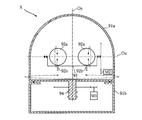
- FIG. 8 shows an example of a conventional radar device.
- the radar apparatus X shown in FIG. 8 includes a pair of Luneberg lenses 92a and a pair of feeds 92b housed in a radome 91a.
- the pair of Luneberg lenses 92a are arranged along the elevation axis Ox.
- the pair of Luneberg lenses 92a and the pair of feeds 92b are provided so as to be rotatable around the azimuth axis Oy together with the radome 91a.
- the radome 91a is supported on the upper wall of the motor chamber 91b.
- the motor M1 is accommodated in the motor chamber 91b.
- the motor M1 is a drive source that drives the rotary shaft 94 extending from the radome 91a.
- the feed 92b is supported by the rotating shaft 93 and is provided to be rotatable around the elevation axis Ox.
- the rotating shaft body 93 is connected to a motor M2 as a drive source.
- the pair of feeds 92b are rotated about the elevation axis Ox with respect to the pair of Luneberg lenses 92a while rotating the entire radome 91a about the azimuth axis Oy.
- weather observation is possible in the range of 0 to 360 degrees in the horizontal direction and in the range of 0 to 90 degrees in elevation from the horizontal plane.
- the present invention has been conceived under the circumstances described above, and an object of the present invention is to provide a rotary drive device capable of realizing both miniaturization and improved operation accuracy, and the rotary drive device. It is to provide a radio wave lens antenna device provided.
- the rotary drive device includes first and second rotary shaft bodies each having an output end and rotating around an axis independently of each other. Further, the apparatus drives the first driven body using the rotational driving force of the output end of the first rotating shaft body as a driving source, and the rotational speed between the output ends of the first and second rotating shaft bodies. The second driven body is driven by the rotational driving force generated by the difference.
- the first rotating shaft body and the second rotating shaft body do not have a subordinate relationship in which one is rotated by the other. For this reason, it is not necessary to rotationally move the drive source for driving the first rotating shaft body and the second rotating shaft body around the first central axis. As a result, it is possible to reduce the size and improve the operation accuracy.
- the first rotating shaft body rotates around a first central axis
- the first and second driven bodies are moved to the first central axis by the rotation of the first rotating shaft body.
- a second central axis that rotates around and extends in a radial direction of a cylindrical coordinate system having the first central axis as a central axis in accordance with a difference in rotational speed between the first rotary shaft body and the second rotary shaft body The second driven body is rotated around.
- the second central axis passes through the first driven body.
- the apparatus further includes a third rotating shaft supported by the first rotating shaft and disposed in parallel to the second central axis.
- the second rotating shaft body and the second driven body are connected to each other through the third rotating shaft body.
- one of the first rotating shaft body and the second rotating shaft body is inserted into the other, and is arranged concentrically in the cross section.
- the second rotating shaft body is connected to the third rotating shaft body through a bevel gear.
- the rotary connection is inserted through the first rotary shaft body and the second rotary shaft body and rotates about the first central axis together with the first rotary shaft body.
- a power supply shaft having a child is further provided.
- a first motor coupled to one of the first rotating shaft body and the second rotating shaft body, an input shaft coupled to the first motor, and the first
- a differential speed reducer having an output shaft connected to one of the rotating shaft body and the second rotating shaft body, and a differential shaft that causes a difference between the rotational speed of the output shaft and the rotational speed of the input shaft
- a second motor coupled to the differential shaft of the differential reducer.
- a rotation amount detecting means for detecting the rotation amount of the second motor is further provided.
- a first motor coupled to one of the first rotating shaft body and the second rotating shaft body, and the first rotating shaft body and the second rotating shaft body.
- a second motor coupled to the other.
- the radio wave lens antenna device of the present invention is a radio wave lens antenna device provided with the above-described rotation drive device.
- the radio wave lens antenna apparatus further comprises: a radio wave lens formed using a dielectric so that a relative permittivity changes in a predetermined ratio in a radial direction; and a primary radiator disposed at a focal portion of the radio wave lens.
- the radio wave lens is the first driven body.
- the primary radiator is the second driven body.
- the first rotating shaft rotates as a first central axis that is an azimuth axis.
- the radio wave lens and the primary radiator are supported by the first rotating shaft body so as to be rotatable around the azimuth axis.
- the primary radiator is provided so as to be rotatable around a second central axis that is an elevation axis and passes through the center of the radio wave lens.
- the rotation around the azimuth axis and the rotation around the elevation axis can be controlled independently.
- the radio wave lens antenna device further includes a radome that covers the radio wave lens and the primary radiator.
- the radome is fixed on the motor chamber, and the first rotating shaft body is inserted through an opening provided in a partition wall between the radome and the motor chamber.
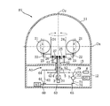
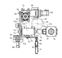
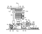
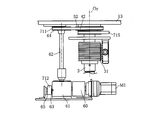
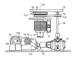
- FIG. 1 is an overall schematic diagram showing a radar device using a rotary drive device according to an embodiment of the present invention. It is principal part sectional drawing of the outer cylinder axis
- FIG. 1 shows a radar device using a rotary drive device according to an embodiment of the present invention.
- the rotational drive device A1 of this embodiment includes an elevation rod 25, a power feeding shaft 3, an inner cylinder shaft 4, an outer cylinder shaft 5, a differential speed reducer 7, and motors M1 and M2.
- the rotation driving device A1 includes a radome 11, a motor chamber 12, a pair of Luneberg lenses 21, and a pair of feeds 22. These parts constitute the radar device B1.
- the radar device B1 is a bistatic small-scale weather radar used for weather observation such as the size of precipitation areas and precipitation. According to the small-scale weather radar, the observation range is smaller than that of the large-scale weather radar, but it is easy to increase the scanning speed.
- the radome 11 is generally formed by FRP (Fiber Reinforced Plastics).
- FRP Fiber Reinforced Plastics
- the radome 11 is used to protect or waterproof the antenna of the radar device B1 arranged outdoors from strong winds such as typhoons, and has a certain weight for securing strength.
- the upper part of the radome 11 has a dome shape so that it can have high transmission characteristics when radio waves are incident as vertically as possible, and raindrops and snow can easily fall. Has a cylindrical shape.
- the radome 11 houses a pair of Luneberg lenses 21, a pair of feeds 22, and an elevation rod 25.
- the central axis of the cylindrical portion is called the azimuth axis Oy, and the radial axis is called the elevation axis Ox.
- the motor chamber 12 means a cylindrical portion connected to the lower end of the radome 11 and houses the differential speed reducer 7 and the motors M1 and M2.
- the radome 11 and the motor chamber 12 are integrally formed with each other while being separated by a partition wall 13.
- the pair of Luneberg lenses 21 is a kind of dielectric lens and corresponds to an example of the radio wave lens of the present invention.
- the Luneberg lens 21 has a spherical shape and is formed such that the relative dielectric constant changes according to the distance from the center thereof, and is made of a foamed material such as polyethylene resin, polypropylene resin, or polystyrene resin. With such a configuration, the Luneberg lens 21 can function as a radio wave lens having a focal point in almost all directions.
- the pair of Luneberg lenses 21 are arranged side by side in the elevation axis Ox direction, and are supported by the outer cylinder shaft 5.
- the pair of feeds 22 is an example of a radiator used for transmission and reception of high-frequency radio waves such as microwaves, and constitutes a pair of antennas together with the pair of Luneberg lenses 21. For example, one of them is used as a transmitting antenna, and the other of them is used as a receiving antenna.
- the feed 22 is disposed at the focal position of the Luneberg lens 21. High-frequency radio waves are radiated from the feed-side feed 22 toward the center of the Luneberg lens 21. The high frequency radio wave is radiated as a plane wave from the Luneberg lens 21. The high-frequency radio wave (plane wave) reflected by the object is collected by the Luneberg lens 21 on the receiving-side feed 22 arranged at the focal position and picked up by the feed 22.
- a horn antenna, a microstrip antenna, a spiral antenna, a slot antenna, or the like is used. If the antenna has a wavelength order, the size of the entire apparatus can be reduced.
- the pair of feeds 22 are supported by the gear 24 through the bracket 23.
- the gear 24 rotates around the elevation axis Ox.
- the pair of gears 24 mesh with a pair of gears 26 attached to both ends of the elevation rod 25, respectively.
- the elevation rod 25 is rotatably provided around an axis parallel to the elevation axis Ox. When the elevation rod 25 rotates, the pair of feeds 22 rotate around the elevation axis Ox along the outer periphery of the pair of Luneberg lenses 21, respectively.
- the partition wall 13 is provided with an opening through which the outer cylinder shaft 5, the inner cylinder shaft 4, and the power feeding shaft 3 penetrate.
- the outer cylinder shaft 5, the inner cylinder shaft 4, and the power feeding shaft 3 are arranged concentrically with each other with the azimuth axis Oy as a central axis.
- the outer cylinder shaft 5 is provided so as to be rotatable around the azimuth axis Oy with respect to the radome 11, and supports the elevation rod 25 through a support 51. Accordingly, when the outer cylinder shaft 5 rotates around the azimuth axis Oy, the pair of Luneberg lenses 21 and the pair of feeds 22 rotate together around the azimuth axis Oy regardless of the state of the inner cylinder shaft 4.
- the inner cylinder shaft 4 is inserted into the outer cylinder shaft 5 and is provided independently of the outer cylinder shaft 5 so as to be rotatable around the azimuth axis Oy.
- a bevel gear 41 is provided at the upper end of the inner cylinder shaft 4.
- the bevel gear 41 meshes with a bevel gear 27 provided on the elevation rod 25.
- the bevel gear 41 and the bevel gear 27 do not rotate relative to each other.
- the elevation rod 25 does not rotate around an axis parallel to the elevation axis Ox. Therefore, the pair of feeds 22 are stationary with respect to the pair of Luneberg lenses 21, respectively.
- the bevel gear 41 and the bevel gear 27 rotate relatively. In this case, the elevation rod 25 rotates around an axis parallel to the elevation axis Ox. For this reason, the pair of feeds 22 rotate relative to the pair of Luneberg lenses 21 around the elevation axis Ox.
- the feeding shaft 3 is used for feeding power to the feed 22 and is inserted into the inner cylinder shaft 4.
- the power feeding shaft 3 rotates around the azimuth axis Oy together with the outer cylinder shaft 5.
- a slip ring 31 serving as an electron supply is provided at the lower end of the power supply shaft 3.
- the slip ring 31 is a conductive component for supplying power to the rotatable feed 22 from a power supply unit as a fixed portion provided in the motor chamber 12.
- a worm gear 61 is connected to the output shaft 60 of the motor M1.
- the worm gear 61 has output shafts 62 and 63.
- the output shaft 62 extends from the worm gear 61 in the upward direction, and a pulley 64 is provided at the upper end thereof.
- a belt 711 is hung on the pulley 64 and the pulley 52 provided on the outer cylinder shaft 5. Thereby, the outer cylinder shaft 5 is rotated by the rotation of the output shaft 62.
- a pulley 65 is provided on the output shaft 63.
- the differential speed reducer 7 has an input shaft 71, an output shaft 73, and a differential shaft 72.
- the rotational speed N3 of the output shaft 73 becomes larger than the rotational speed N1 of the input shaft 71, and when the differential shaft 72 reverses, the rotational speed N3 of the output shaft 73 becomes the rotational speed of the input shaft 71. It becomes smaller than the number N1.
- the rotational speed N3 of the output shaft 73 and the rotational speed N1 of the input shaft 71 are the same.
- a belt 712 is hung on the pulley 74 provided on the input shaft 71 and the pulley 65 described above. Thereby, the input shaft 71 is rotated by the motor M1.
- the differential shaft 72 is provided with a pulley 75
- the output shaft 70 of the motor M2 is provided with a pulley 76.
- a belt 713 is hung on the pulley 75 and the pulley 76.
- the output shaft 73 is connected to the worm gear 77.
- the worm gear 77 has an output shaft 78 extending in the upward direction.
- a pulley 79 is provided on the output shaft 78.
- a belt 715 is hung on the pulley 79 and the pulley 42 provided on the inner cylinder shaft 4. Thereby, when the output shaft 73 of the differential speed reducer 7 rotates, the inner cylinder shaft 4 rotates.
- an elevation sensor unit 8 is disposed in the vicinity of the motor M2.
- the elevation sensor unit 8 includes an input shaft 80, a moving body 81, and a sensor 82.
- the input shaft 80 and the differential shaft 72 rotate in conjunction with each other via a pulley and a belt 714 provided on each.
- the moving body 81 is a nut portion of a ball screw connected to the input shaft 80, for example.
- the sensor 82 detects the position of the moving body 81 in the linear movement trajectory. By detecting the position of the moving body 81, the rotation direction and the rotation amount of the differential shaft 72 can be detected.
- the rotation drive device A1 and the radar device B1 When performing weather observation using the radar apparatus B1, in the rotational drive apparatus A1, first, the pair of Luneberg lenses 21 and the pair of feeds 22 are rotated as an integral part around the azimuth axis Oy. This is executed by rotating the outer cylinder 5 by the motor M1. At this time, if the motor M2 is kept stationary, the inner cylinder shaft 4 rotates at the same rotational speed as the outer cylinder shaft 5. In this case, the pair of feeds 22 do not rotate relative to the pair of Luneberg lenses 21, respectively. By rotating around the azimuth axis Oy, it becomes possible to observe all directions from 0 to 360 degrees in the horizontal direction.
- each of the pair of feeds 22 is rotated around the elevation axis Ox along the outer periphery of the pair of Luneberg lenses 21.
- the motor M2 is rotated to cause a difference between the rotation speed of the outer cylinder shaft 5 and the rotation speed of the inner cylinder shaft 4.
- the pair of feeds 22 rotate around the elevation axis Ox along the outer periphery of the pair of Luneberg lenses 21 in accordance with the rotational speed difference.
- the radar apparatus B1 can perform meteorological observation of the entire region of the desired sky from the observation point.
- the pair of Luneberg lenses 21 and the pair of feeds 22 when the pair of Luneberg lenses 21 and the pair of feeds 22 are rotated about the azimuth axis Oy, the pair of feeds 22 can be further rotated about the elevation axis Ox. Nevertheless, the two motors M1 and M2 themselves are both fixed in the motor chamber 12 and do not rotate. In other words, only the minimum necessary components such as the pair of Luneberg lenses 21, the pair of feeds 22, and the elevation rod 25 are rotationally moved around the azimuth axis Oy. Further, the radome 11 is fixed as an integral part of the motor chamber 12 without rotating around the azimuth axis Oy.
- the motor M2 may be rotated by an amount corresponding to the amount by which the pair of feeds 22 is rotated. That is, the rotation direction of the motor M2 and the rotation direction of the pair of feeds 22 coincide with each other, and the rotation amount of the motor M2 and the rotation amount of the pair of feeds 22 have a proportional relationship. For this reason, as long as the rotation of the motor M2 is accurately controlled, the pair of feeds 22 can be accurately arranged at a desired position with respect to the pair of Luneberg lenses 21. This is suitable for increasing the observation accuracy of the radar device B1.
- the elevation sensor unit 8 is disposed in the motor chamber 12 isolated from the pair of feeds 22 in spite of the detection of the positions of the pair of feeds 22. This is advantageous for accurately detecting the position of the pair of feeds 22 and reducing the size of the radome 11.
- FIG. 7 shows a radar apparatus using a rotary drive apparatus according to another embodiment of the present invention.
- the rotational drive device A2 of the present embodiment is used as a drive unit of the radar device B2, and a mechanism for driving the outer cylinder shaft 5 and the inner cylinder shaft 4 is different from the above-described rotation drive device A1.
- the pulley 64 provided on the output shaft 60 of the motor M1 and the pulley 52 of the outer cylinder shaft 5 are connected by a belt (not shown).
- the pulley 79 provided on the output shaft 70 of the motor M2 and the pulley 42 of the inner cylinder shaft 4 are connected by a belt (not shown).
- the motors M1 and M2 are synchronously rotated, and both rotation speeds are set to be the same. is doing. Accordingly, there is no difference between the rotational speed of the outer cylindrical shaft 5 and the rotational speed of the inner cylindrical shaft 4, so that the pair of feeds 22 do not rotate with respect to the pair of Luneberg lenses 21.
- rotation of the motor M2 in order to rotate the pair of feeds 22 around the elevation axis Ox along the outer periphery of the Luneberg lens 21, rotation of the motor M2 with respect to the rotation speed of the motor M1. Just increase or decrease the number.
- the number of components to be accommodated in the radome 11 can be reduced, and both the downsizing of the radar apparatus B2 and the improvement of observation accuracy can be realized. Furthermore, it becomes easy to increase the scanning speed of the radar device B2. Further, it is possible to suppress a complicated mechanism for driving the outer cylinder shaft 5 and the inner cylinder shaft 4.
- the weather radar device has been described as an example of the device of the present invention, but the present invention is not limited to this.
- the device of the present invention may be a communication antenna device, for example.
- the present invention it is possible to realize both miniaturization and improvement of operation accuracy, and it is possible to provide an apparatus that can be used for various purposes such as weather radar.
- A1, A2 rotary drive device, B1, B2 radar device M1 (first) motor, M2 (second) motor, Ox elevation axis (second central axis), Oy azimuth axis (first central axis), 3 feeding Shaft, 4 inner cylinder shaft (second rotating shaft body), 5 outer cylinder shaft (first rotating shaft body), 7 differential reducer, 8 elevation sensor unit, 11 radome, 12 motor room, 21 Luneberg lens ( 1st driven body), 22 feed (second driven body), 23 bracket, 24 gear, 25 elevation rod (third rotating shaft body), 26 gear, 27 bevel gear, 31 slip ring (electronic supply), 41 bevel gear, 42 pulley, 51 support, 52 pulley, 60 output shaft, 61 worm gear, 62, 63 output shaft, 64, 65 pulley, 70 Output shaft, 71 input shaft, 72 differential shaft, 73 output shaft, 74, 75 pulley, 77 worm, 78 output shaft, 79 pulley, 711-715 belt, 81 movable body
Landscapes
- Engineering & Computer Science (AREA)
- Radar, Positioning & Navigation (AREA)
- Remote Sensing (AREA)
- Computer Networks & Wireless Communication (AREA)
- Physics & Mathematics (AREA)
- General Physics & Mathematics (AREA)
- Variable-Direction Aerials And Aerial Arrays (AREA)
- Aerials With Secondary Devices (AREA)
- Radar Systems Or Details Thereof (AREA)
Abstract
Description
レーダー装置B1を用いた気象観測をする場合、回転駆動装置A1においては、まず、一対のルネベルグレンズ21と一対のフィード22とをアジマス軸Oy周りに一体的な部分として回転させる。これは、モータM1によって外筒5を回転させることによって実行される。このとき、モータM2を静止させておくと、内筒軸4が外筒軸5と同じ回転数で回転する。この場合、一対のフィード22は、それぞれ、一対のルネベルグレンズ21に対して相対的に回転しない。アジマス軸Oy周りの回転によって水平方位の0~360度の全方位を観測することが可能となる。次に、アジマス軸Oy周りの回転に加えて、一対のフィード22のそれぞれを一対のルネベルグレンズ21の外周に沿ってエレベーション軸Ox周りに回転させる。これにより、各水平方位での仰角0から90度の範囲における気象観測をすることが可能となる。このときには、モータM2を回転させることにより、外筒軸5の回転数と内筒軸4の回転数とに差を生じさせる。この回転数差に応じて一対のフィード22が一対のルネベルグレンズ21の外周に沿ってエレベーション軸Ox周りに回転する。モータM2の正転および逆転を切り換えることにより、レーダー装置B1は、観測地点から所望の天空の全領域の気象観測を行うことができる。
Claims (12)
- 第1被駆動体(21)を駆動するように回転する第1回転軸体(5)と、
前記第1回転軸体(5)の回転から独立して回転することが可能な第2回転軸体(4)とを備え、
前記第1回転軸体(5)の回転数と前記第2回転軸体(4)の回転数との差によって生じる回転駆動力を用いて第2被駆動体(22)を駆動する、回転駆動装置(A1,A2)。 - 前記第1回転軸体(5)が第1中心軸(Oy)まわりに回転することにより、前記第1被駆動体(21)および前記第2被駆動体(22)が前記第1中心軸(Oy)まわりに回転し、
前記第1中心軸(Oy)を中心軸とする円筒座標系において、第2中心軸(Ox)が径方向に延びており、
前記第1回転軸体(5)の回転数と前記第2回転軸体(4)の回転数との差に応じて、前記第2中心軸(Ox)まわりに前記第2被駆動体(22)が回転する、請求項1に記載の回転駆動装置(A1,A2)。 - 前記第2中心軸(Ox)は、前記第1被駆動体(21)を貫通している、請求項2に記載の回転駆動装置(A1,A2)。
- 前記第1回転軸体(5)および前記第2回転軸体(4)の内部に挿通されており、前記第1回転軸体(5)とともに前記第1中心軸(Oy)まわりに回転する回転接続子を有し、前記第2被駆動体(22)に電力を供給するための給電軸(3)をさらに備えた、請求項2に記載の回転駆動装置(A1,A2)。
- 前記第1回転軸体(5)によって支持されており、かつ前記第2中心軸(Ox)に対して平行に配置された第3回転軸体(25)をさらに備えており、
前記第2回転軸体(4)と前記第2被駆動体(22)とは、前記第3回転軸体(25)を媒介として連結されている、請求項2に記載の回転駆動装置(A1,A2)。 - 前記第2回転軸体(4)は、ベベルギア(27,41)を介して前記第3回転軸体(25)に連結されている、請求項5に記載の回転駆動装置(A1,A2)。
- 前記第1回転軸体(5)と前記第2回転軸体(4)とは、一方が他方の内部に挿通されることにより、断面において同心円状に配置されている、請求項1に記載の回転駆動装置(A1,A2)。
- 前記第1回転軸体(5)および前記第2回転軸体(4)のいずれか一方に連結された第1モータ(M1)と、
前記第1モータ(M1)に連結された入力軸(71)と、
前記第1回転軸体(5)および前記第2回転軸体(4)のいずれか他方に連結された出力軸(73)と、
前記出力軸(73)の回転数と前記入力軸(71)の回転数とに差を生じさせる差動軸(72)を有する差動減速器(7)と、
前記差動減速器(7)の前記差動軸(72)に連結された第2モータ(M2)とをさらに備えた、請求項1に記載の回転駆動装置(A1)。 - 前記第2モータ(M2)の回転量を検出する回転量検出手段(8)をさらに備えた、請求項8に記載の回転駆動装置(A1)。
- 前記第1回転軸体(5)および前記第2回転軸体(4)のいずれか一方に連結された第1モータ(M1)と、
前記第1回転軸体(5)および前記第2回転軸体(4)の他方に連結された第2モータ(M2)とをさらに備えた、請求項1に記載の回転駆動装置(A2)。 - 請求項1に記載の回転駆動装置(A1,A2)と、
前記第1被駆動体としての、誘電体を用いて比誘電率が半径方向に所定の割合で変化するように形成された電波レンズ(21)と、
前記第2被駆動体としての、前記電波レンズ(21)の焦点部に配置された一次放射器(22)とを備え、
前記電波レンズ(21)および前記一次放射器(22)は、前記第1回転軸体(5)により、アジマス軸(Oy)まわりに回転可能に支持され、
前記一次放射器(22)は、前記電波レンズ(21)の中心を通るエレベーション軸(Ox)まわりに回転可能に設けられた、電波レンズアンテナ装置(B1,B2)。 - 前記電波レンズ(21)および前記一次放射器(22)をカバーするレドーム(11)をさらに備え、
前記レドーム(11)は、モータ室(12)上に固定され、
前記第1回転軸体(5)は、前記レドーム(11)と前記モータ室(12)との間の隔壁(13)に設けられた開口に挿通された、請求項11に記載の電波レンズアンテナ装置(B1,B2)。
Priority Applications (2)
| Application Number | Priority Date | Filing Date | Title |
|---|---|---|---|
| CN201180032565.2A CN102959798B (zh) | 2010-06-28 | 2011-06-16 | 电磁透镜天线装置 |
| KR1020137000253A KR101726911B1 (ko) | 2010-06-28 | 2011-06-16 | 회전 구동 장치 및 전파 렌즈 안테나 장치 |
Applications Claiming Priority (2)
| Application Number | Priority Date | Filing Date | Title |
|---|---|---|---|
| JP2010146183A JP5654785B2 (ja) | 2010-06-28 | 2010-06-28 | 回転駆動装置および電波レンズアンテナ装置 |
| JP2010-146183 | 2010-06-28 |
Publications (1)
| Publication Number | Publication Date |
|---|---|
| WO2012002160A1 true WO2012002160A1 (ja) | 2012-01-05 |
Family
ID=45401885
Family Applications (1)
| Application Number | Title | Priority Date | Filing Date |
|---|---|---|---|
| PCT/JP2011/063817 Ceased WO2012002160A1 (ja) | 2010-06-28 | 2011-06-16 | 回転駆動装置および電波レンズアンテナ装置 |
Country Status (4)
| Country | Link |
|---|---|
| JP (1) | JP5654785B2 (ja) |
| KR (1) | KR101726911B1 (ja) |
| CN (1) | CN102959798B (ja) |
| WO (1) | WO2012002160A1 (ja) |
Families Citing this family (11)
| Publication number | Priority date | Publication date | Assignee | Title |
|---|---|---|---|---|
| WO2012161612A1 (en) | 2011-05-23 | 2012-11-29 | Autonomous Non-Commercial Organization "Research Institute "Sitronics Labs"" | Electronically beam steerable antenna device |
| RU2585309C2 (ru) | 2011-10-20 | 2016-05-27 | Общество с ограниченной ответственностью "Радио Гигабит" | Система и способ радиорелейной связи с электронной подстройкой луча |
| WO2013150994A1 (ja) * | 2012-04-02 | 2013-10-10 | 古野電気株式会社 | アンテナ装置 |
| RU2494506C1 (ru) * | 2012-07-10 | 2013-09-27 | Общество с ограниченной ответственностью "Радио Гигабит" | Линзовая антенна с электронным сканированием луча |
| EP2884582A4 (en) * | 2012-08-07 | 2016-02-10 | Intellian Technologies Inc | SATELLITE ANTENNA HOUSING |
| KR101398495B1 (ko) * | 2012-08-07 | 2014-05-27 | (주)인텔리안테크놀로지스 | 선박 탑재 광대역 위성안테나용 하우징 |
| RU2530330C1 (ru) | 2013-03-22 | 2014-10-10 | Общество с ограниченной ответственностью "Радио Гигабит" | Станция радиорелейной связи со сканирующей антенной |
| KR101657176B1 (ko) * | 2015-11-03 | 2016-09-19 | (주)인텔리안테크놀로지스 | 위성 추적 안테나용 페데스탈 장치 |
| CN107436425A (zh) * | 2016-05-26 | 2017-12-05 | 中船重工海博威(江苏)科技发展有限公司 | 一种集成旋转式低辐射控制固态雷达 |
| LU100258B1 (en) * | 2017-05-19 | 2019-01-04 | Iee Sa | Tunable Metamaterial Lens for Radar Sensing |
| CN108562874B (zh) * | 2018-04-14 | 2020-05-15 | 安徽工程大学 | 一种抗风雷达罩 |
Citations (3)
| Publication number | Priority date | Publication date | Assignee | Title |
|---|---|---|---|---|
| JPH02308111A (ja) * | 1989-05-23 | 1990-12-21 | Fujikura Ltd | 光ファィバケーブル製造装置 |
| WO2008016033A1 (en) * | 2006-08-02 | 2008-02-07 | Sei Hybrid Products, Inc. | Radar |
| JP2009002263A (ja) * | 2007-06-22 | 2009-01-08 | Mecaro:Kk | マグナス型風力発電装置及びその制御方法 |
Family Cites Families (1)
| Publication number | Priority date | Publication date | Assignee | Title |
|---|---|---|---|---|
| JP4816078B2 (ja) | 2005-12-28 | 2011-11-16 | 住友電気工業株式会社 | 電波レンズアンテナ装置 |
-
2010
- 2010-06-28 JP JP2010146183A patent/JP5654785B2/ja not_active Expired - Fee Related
-
2011
- 2011-06-16 KR KR1020137000253A patent/KR101726911B1/ko not_active Expired - Fee Related
- 2011-06-16 WO PCT/JP2011/063817 patent/WO2012002160A1/ja not_active Ceased
- 2011-06-16 CN CN201180032565.2A patent/CN102959798B/zh not_active Expired - Fee Related
Patent Citations (3)
| Publication number | Priority date | Publication date | Assignee | Title |
|---|---|---|---|---|
| JPH02308111A (ja) * | 1989-05-23 | 1990-12-21 | Fujikura Ltd | 光ファィバケーブル製造装置 |
| WO2008016033A1 (en) * | 2006-08-02 | 2008-02-07 | Sei Hybrid Products, Inc. | Radar |
| JP2009002263A (ja) * | 2007-06-22 | 2009-01-08 | Mecaro:Kk | マグナス型風力発電装置及びその制御方法 |
Also Published As
| Publication number | Publication date |
|---|---|
| JP5654785B2 (ja) | 2015-01-14 |
| CN102959798A (zh) | 2013-03-06 |
| KR20130098270A (ko) | 2013-09-04 |
| KR101726911B1 (ko) | 2017-04-13 |
| JP2012010245A (ja) | 2012-01-12 |
| CN102959798B (zh) | 2015-03-25 |
Similar Documents
| Publication | Publication Date | Title |
|---|---|---|
| JP5654785B2 (ja) | 回転駆動装置および電波レンズアンテナ装置 | |
| EP3322035B1 (en) | Antenna | |
| EP2302409B1 (en) | Weather radar apparatus comprising an electromagnetic lens antenna device | |
| EP2051097B1 (en) | Radar | |
| EP2835865B1 (en) | Antenna device | |
| CN101533962B (zh) | 亚毫米波准光馈电圆锥扫描跟踪天线 | |
| CN102253387B (zh) | 一种用于毫米波和亚毫米波的双模辐射计系统 | |
| WO2020132621A1 (en) | Antenna system | |
| ES2694245T3 (es) | Antena direccionable | |
| CN108987929A (zh) | 一种微波毫米波紧凑相控阵天线系统 | |
| WO2008015757A1 (en) | Wind speed radar | |
| EP1362385B1 (en) | Scanning antenna systems | |
| CN108401574B (zh) | 一种天线指向调整机构 | |
| CN205376768U (zh) | 具有综合探测性能的昆虫探测雷达天线馈线系统 | |
| US10483651B2 (en) | Transmit-array antenna comprising a mechanism for reorienting the direction of the beam | |
| CN113809539B (zh) | 一种电机控制圆极化天线旋转的阵列波束偏转系统 | |
| JP7144083B2 (ja) | アンテナ装置 | |
| CN222940821U (zh) | 一种无人机反制设备 | |
| CN223486188U (zh) | 一种偏轴式多模探测装置 | |
| CN212539346U (zh) | 电石炉电极糊测量系统 | |
| WO2013019161A1 (en) | System with anti-cable twisting mechanism and method thereof | |
| EP4726921A1 (en) | Beam-steering antenna | |
| CN215264008U (zh) | 微波雷达及可移动平台 | |
| US20240283146A1 (en) | Spherical reflector antenna having waveguide feed system | |
| CN107834204A (zh) | 一种电调天线控制器及天线传动装置 |
Legal Events
| Date | Code | Title | Description |
|---|---|---|---|
| WWE | Wipo information: entry into national phase |
Ref document number: 201180032565.2 Country of ref document: CN |
|
| 121 | Ep: the epo has been informed by wipo that ep was designated in this application |
Ref document number: 11800626 Country of ref document: EP Kind code of ref document: A1 |
|
| NENP | Non-entry into the national phase |
Ref country code: DE |
|
| ENP | Entry into the national phase |
Ref document number: 20137000253 Country of ref document: KR Kind code of ref document: A |
|
| 122 | Ep: pct application non-entry in european phase |
Ref document number: 11800626 Country of ref document: EP Kind code of ref document: A1 |