WO2012002103A1 - 機能補完集積回路、集積回路システムおよびこれらを使用した医療機器 - Google Patents
機能補完集積回路、集積回路システムおよびこれらを使用した医療機器 Download PDFInfo
- Publication number
- WO2012002103A1 WO2012002103A1 PCT/JP2011/062807 JP2011062807W WO2012002103A1 WO 2012002103 A1 WO2012002103 A1 WO 2012002103A1 JP 2011062807 W JP2011062807 W JP 2011062807W WO 2012002103 A1 WO2012002103 A1 WO 2012002103A1
- Authority
- WO
- WIPO (PCT)
- Prior art keywords
- processor
- integrated circuit
- abnormality
- function
- detection signal
- Prior art date
- Legal status (The legal status is an assumption and is not a legal conclusion. Google has not performed a legal analysis and makes no representation as to the accuracy of the status listed.)
- Ceased
Links
Images




Classifications
-
- A—HUMAN NECESSITIES
- A61—MEDICAL OR VETERINARY SCIENCE; HYGIENE
- A61B—DIAGNOSIS; SURGERY; IDENTIFICATION
- A61B5/00—Measuring for diagnostic purposes; Identification of persons
- A61B5/145—Measuring characteristics of blood in vivo, e.g. gas concentration or pH-value ; Measuring characteristics of body fluids or tissues, e.g. interstitial fluid or cerebral tissue
- A61B5/14532—Measuring characteristics of blood in vivo, e.g. gas concentration or pH-value ; Measuring characteristics of body fluids or tissues, e.g. interstitial fluid or cerebral tissue for measuring glucose, e.g. by tissue impedance measurement
-
- A—HUMAN NECESSITIES
- A61—MEDICAL OR VETERINARY SCIENCE; HYGIENE
- A61B—DIAGNOSIS; SURGERY; IDENTIFICATION
- A61B5/00—Measuring for diagnostic purposes; Identification of persons
- A61B5/02—Detecting, measuring or recording for evaluating the cardiovascular system, e.g. pulse, heart rate, blood pressure or blood flow
- A61B5/021—Measuring pressure in heart or blood vessels
- A61B5/022—Measuring pressure in heart or blood vessels by applying pressure to close blood vessels, e.g. against the skin; Ophthalmodynamometers
-
- A—HUMAN NECESSITIES
- A61—MEDICAL OR VETERINARY SCIENCE; HYGIENE
- A61B—DIAGNOSIS; SURGERY; IDENTIFICATION
- A61B5/00—Measuring for diagnostic purposes; Identification of persons
- A61B5/48—Other medical applications
- A61B5/4836—Diagnosis combined with treatment in closed-loop systems or methods
- A61B5/4839—Diagnosis combined with treatment in closed-loop systems or methods combined with drug delivery
-
- A—HUMAN NECESSITIES
- A61—MEDICAL OR VETERINARY SCIENCE; HYGIENE
- A61M—DEVICES FOR INTRODUCING MEDIA INTO, OR ONTO, THE BODY; DEVICES FOR TRANSDUCING BODY MEDIA OR FOR TAKING MEDIA FROM THE BODY; DEVICES FOR PRODUCING OR ENDING SLEEP OR STUPOR
- A61M5/00—Devices for bringing media into the body in a subcutaneous, intra-vascular or intramuscular way; Accessories therefor, e.g. filling or cleaning devices, arm-rests
- A61M5/14—Infusion devices, e.g. infusing by gravity; Blood infusion; Accessories therefor
- A61M5/168—Means for controlling media flow to the body or for metering media to the body, e.g. drip meters, counters ; Monitoring media flow to the body
- A61M5/172—Means for controlling media flow to the body or for metering media to the body, e.g. drip meters, counters ; Monitoring media flow to the body electrical or electronic
-
- A—HUMAN NECESSITIES
- A61—MEDICAL OR VETERINARY SCIENCE; HYGIENE
- A61M—DEVICES FOR INTRODUCING MEDIA INTO, OR ONTO, THE BODY; DEVICES FOR TRANSDUCING BODY MEDIA OR FOR TAKING MEDIA FROM THE BODY; DEVICES FOR PRODUCING OR ENDING SLEEP OR STUPOR
- A61M5/00—Devices for bringing media into the body in a subcutaneous, intra-vascular or intramuscular way; Accessories therefor, e.g. filling or cleaning devices, arm-rests
- A61M5/14—Infusion devices, e.g. infusing by gravity; Blood infusion; Accessories therefor
- A61M5/168—Means for controlling media flow to the body or for metering media to the body, e.g. drip meters, counters ; Monitoring media flow to the body
- A61M5/172—Means for controlling media flow to the body or for metering media to the body, e.g. drip meters, counters ; Monitoring media flow to the body electrical or electronic
- A61M5/1723—Means for controlling media flow to the body or for metering media to the body, e.g. drip meters, counters ; Monitoring media flow to the body electrical or electronic using feedback of body parameters, e.g. blood-sugar, pressure
-
- A—HUMAN NECESSITIES
- A61—MEDICAL OR VETERINARY SCIENCE; HYGIENE
- A61M—DEVICES FOR INTRODUCING MEDIA INTO, OR ONTO, THE BODY; DEVICES FOR TRANSDUCING BODY MEDIA OR FOR TAKING MEDIA FROM THE BODY; DEVICES FOR PRODUCING OR ENDING SLEEP OR STUPOR
- A61M2205/00—General characteristics of the apparatus
- A61M2205/18—General characteristics of the apparatus with alarm
-
- A—HUMAN NECESSITIES
- A61—MEDICAL OR VETERINARY SCIENCE; HYGIENE
- A61M—DEVICES FOR INTRODUCING MEDIA INTO, OR ONTO, THE BODY; DEVICES FOR TRANSDUCING BODY MEDIA OR FOR TAKING MEDIA FROM THE BODY; DEVICES FOR PRODUCING OR ENDING SLEEP OR STUPOR
- A61M2230/00—Measuring parameters of the user
- A61M2230/20—Blood composition characteristics
- A61M2230/201—Glucose concentration
Definitions
- the present invention relates to a function-complementary integrated circuit, an integrated circuit system, and a medical device using these.
- an internal circuit of a medical device has been configured by hybrid mounting electronic components such as a microcomputer and an operational amplifier on a wiring board.
- Patent Document 1 is a technique for realizing a reduction in the cost of a component by integrating a plurality of components on a single integrated circuit (one-chip).
- the present invention has been made to solve such a problem, and an object thereof is to realize further cost reduction of medical device parts and medical devices using the same.
- a function-complementary integrated circuit is used in at least one of a plurality of medical devices, and complements some functions of a common processor used for each of the plurality of medical devices.
- An abnormality detection signal transmission unit that transmits an abnormality detection signal for detecting an abnormality of the integrated circuit to the processor, and the abnormality detection signal that indicates the abnormality of the processor is received from the processor.
- a processor monitoring unit that stops some functions and controls the medical device to the safe side.
- an integrated circuit system is used in at least one of a plurality of medical devices, and a function-complementary integrated circuit that supplements some functions of a common processor used for each of the plurality of medical devices; And a processor having the function supplemented by the function complementing integrated circuit, wherein the function complementing integrated circuit complements the processor when receiving an abnormality monitoring signal indicating an abnormality of the processor from the processor.
- Monitoring unit for controlling the medical device to the safe side, an abnormality detection signal transmission unit for transmitting an abnormality detection signal for detecting an abnormality of the function-complementary integrated circuit to the processor, and an abnormality detection signal
- An abnormality detection signal receiving unit for receiving an abnormality detection signal transmitted by the processor when the processor detects an abnormality in the function-complementary integrated circuit, and an abnormality
- a shutoff control signal output unit that outputs a shutoff control signal used to shut off a control signal supplied to the medical device in order to supplement the partial function when the intelligent signal receiving unit receives the abnormality detection signal;
- the processor includes an abnormality monitoring signal transmission unit that transmits an abnormality monitoring signal indicating an abnormality of the processor, and a safety control unit that controls the medical device to the safe side when an abnormality of the function-complementary integrated circuit is detected,
- the medical device according to the present invention uses the above-described function-complementary integrated circuit or the above-described integrated circuit system.
- a processor used for a plurality of medical devices is customized and shared, and a highly functional device is customized to supplement a part of the functions of the processor.
- Function-complementary integrated circuits are used in combination with processors.
- the processor and the function-complementary integrated circuit are monitored for abnormalities, and when an abnormality occurs, the medical device is controlled to the safe side.
- FIG. 1 It is a figure which shows the functional block diagram of a syringe pump and an infusion pump among the medical devices which concern on embodiment of this invention. It is a figure which shows the functional block diagram of a blood glucose meter and a blood pressure meter among the medical devices which concern on embodiment of this invention. It is a block diagram which shows the connection relationship of a processor, a gate array, and a peripheral device among the components of the medical device which concerns on embodiment of this invention, and the timing chart of the control signal of these peripheral devices. It is a block diagram which shows the connection relationship of a processor, a gate array, and a peripheral device among the components of the medical device which concerns on this embodiment when a processor is abnormal, and the timing chart of the control signal of a peripheral device.
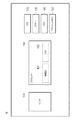
- FIG. 1 is a functional block diagram of a syringe pump and an infusion pump in the medical device according to the present embodiment.
- FIG. 2 is a functional block diagram of a blood glucose meter and a blood pressure meter among the medical devices according to the present embodiment.
- FIGS. 1 and 2 some functional blocks of the medical device are omitted.
- Syringe pumps are medical devices whose main purpose is to perform nutritional supplementation and blood transfusion for patients, chemotherapeutic agents and anesthetics for a long period of time with high accuracy in intensive care units (ICU).
- ICU intensive care units
- the chemical flow control is superior to other types of pumps.
- An infusion pump is a medical device that continuously administers a drug at a set amount of infusion per hour, and is used when, for example, it is desired to accurately infuse a patient after surgery.
- the blood pressure monitor is a medical device that measures human blood pressure
- the blood glucose meter is a medical device that measures human blood glucose level.
- the same processor 100 is commonly used for the medical devices 10 and 11 according to the present embodiment.
- the processor 100 may include the amplification unit 101 and other elements.
- the processor 100 may be configured by only a CPU (Central Processing Unit) 102, and the amplification unit 101 and other elements may be configured by separate chips.
- CPU Central Processing Unit
- the sensor 120 includes an occlusion pressure sensor when the medical device 10 is a syringe pump and an infusion pump, a pressure sensor and a microphone when the medical device 11 is a blood pressure monitor, and a blood glucose sensor when the medical device 11 is a blood glucose meter. Is applicable.
- the CPU 102 included in the processor 100 performs an operation based on the amplified detection signal, calculates a detection result, and controls the medical devices 10 and 11.
- the detection result by the sensor 120 is recorded in the flash memory 150 provided in the medical devices 10 and 11 and can be displayed on an LCD (Liquid Crystal Display) 140. Further, when it is determined that the measurement is completed or when an abnormality is detected, the buzzer 130 provided in the medical devices 10 and 11 is sounded, and the LED (Light Emitting Diode) 170 is controlled to be turned on or blinking.
- LCD Liquid Crystal Display
- a motor 160 that drives a pump (not shown) is controlled based on the detection result of the sensor 120.
- the syringe pump and the infusion pump that are the medical devices 10 according to the present embodiment use a gate array (function-complementary integrated circuit) 110 together with a processor 100.
- a gate array function-complementary integrated circuit
- the processor 100 used for the syringe pump and the infusion pump is required to have a relatively high arithmetic processing capability and a high function.
- the processor 100 used for the sphygmomanometer and the blood glucose meter does not need to be as sophisticated as the processor 100 used for the syringe pump and the infusion pump. For this reason, if it is going to achieve the function of all the four medical devices 10 and 11 mentioned above by the same processor 100, the function of the processor 100 must be matched with a syringe pump and an infusion pump, and is used for a blood pressure meter and a blood glucose meter. In that case, the processor 100 is over spec. That is, the chip size of the processor 100 is increased, and it becomes difficult to reduce the component cost.
- the processor 100 used in common for the medical devices 10 and 11 is assumed to have a relatively low function sufficient to achieve the functions of the blood pressure monitor and the blood glucose meter. And when the processor 100 is used for a syringe pump and an infusion pump, the processor 100 and the gate array 110 are connected. That is, for example, the gate array 110 is supplemented with the function of the processor 100 by causing the gate array 110 to control peripheral devices that require relatively high arithmetic processing capability for the control, such as the motor 160 and the LCD 140.
- the processor 100 and the gate array 110 are connected to each other to constitute an integrated circuit system that realizes a high function or a plurality of functions.
- the gate array 110 is not used for the blood glucose meter and the blood pressure monitor that are the medical device 11 according to the present embodiment.
- the medical devices 10 and 11 use the gate array 110 in accordance with their functions.
- the gate array 110 is configured to complement some functions of the processor 100.
- the gate array 110 may be, for example, a gate array that is customized by changing a wiring (for example, an aluminum master slice method), or a gate array that is programmable and customized by writing or rewriting a logic circuit (for example, An FPGA (Field Programmable Gate Array) may be used.
- a gate array that is customized by changing a wiring for example, an aluminum master slice method
- a gate array that is programmable and customized by writing or rewriting a logic circuit for example, An FPGA (Field Programmable Gate Array) may be used.
- the processor 100 used for the plurality of medical devices 10 and 11 is customized and shared, and a part of the processor 100 is used for a highly functional device.
- a customized gate array 110 that complements these functions is used in conjunction with the processor 100.
- the medical devices 10 and 11 even if the functions of some of the components of the platform integrated circuit 100 are configured to have relatively low functions, higher functions than the functions are required.
- the scope of application can be expanded to the measuring device to be used. For this reason, parts costs can be further reduced by the mass production effect.
- the processor 100 and the gate array 110 may be configured by a full custom ASIC (Application Specific Integrated Circuit), or may be configured by a semi-custom standard cell.
- ASIC Application Specific Integrated Circuit
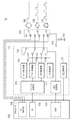
- FIG. 3 is a block diagram showing a connection relationship between a processor, a gate array, and peripheral devices among components of the medical device according to the embodiment of the present invention, and a timing chart of control signals of these peripheral devices.
- the components of the medical device 10 according to this embodiment shown in FIG. 3 are elements relating to the fail-safe function of the syringe pump and the infusion pump.
- the fail-safe function is a function that always controls the medical device 10 to the safe side when an abnormality occurs in the medical device 10.
- the processor 100 includes a WDT (Watch Dog Timer, abnormality monitoring signal transmission unit) 103, a fail safe control unit (safety control unit, second alarm control signal output unit) 104, and a serial communication unit 105.
- WDT Watch Dog Timer, abnormality monitoring signal transmission unit
- fail safe control unit safety control unit, second alarm control signal output unit
- serial communication unit 105 serial communication unit
- the WDT 103 is a timer for monitoring the normal execution state of the program in the processor 100.
- the WDT 103 outputs a count-up signal (pulse signal) when the processor 100 is normal, and outputs a constant DC signal without outputting the count-up signal when the processor 100 is abnormal.
- the output signal of the WDT 103 is referred to as an abnormality monitoring signal.
- the fail safe control unit 104 is a signal for stopping the motor 160, a signal for sounding the buzzer 130, and a signal for lighting or blinking the LED 170 (hereinafter referred to as "fail safe control signal") when the gate array 110 is abnormal. Output).
- the fail safe control unit 104 controls the medical device 10 to the safe side by stopping the motor 160 when the gate array 110 is abnormal.
- the serial communication unit 105 transmits / receives verification test data for detecting an abnormality of the gate array 110 to / from the serial communication unit 118 of the gate array 110.
- the verification test data is transmitted / received by serial data, but may be performed by parallel data.
- the serial communication unit 105 detects an abnormality of the gate array 110 by a verify test, and transmits data notifying the abnormality of the gate array 110 to the fail safe control unit 104. The verification test will be described later.
- the gate array 110 includes a WDT monitoring unit (processor monitoring unit) 111, a fail safe control unit (processor monitoring unit, an alarm control signal output unit, a first alarm control signal output unit) 112, a self-diagnosis unit (an abnormality detection signal transmission unit). ) 113, switch 114, motor control unit 115, buzzer control unit 116, LED control unit 117, serial communication unit (abnormality detection signal transmission unit, abnormality detection signal reception unit) 118, and cutoff control signal output unit 119.
- the WDT monitoring unit 111 receives the abnormality monitoring signal from the WDT 103, and thereby monitors the processor 100. Further, the abnormality of the processor 100 is detected based on the abnormality monitoring signal.
- the fail safe control unit 112 outputs a fail safe control signal. When the processor 100 is abnormal, the switch 114 is switched so that the fail safe control signal generated by the fail safe control unit 112 is output from the gate array 110. Note that the fail-safe control signal generated by the fail-safe control unit 112 of the gate array 110 may be the same as the fail-safe control signal generated by the fail-safe control unit 104 of the processor 100.
- the self-diagnosis unit 113 determines the abnormality of the gate array 110 by itself, and when abnormal, transmits a signal (an abnormality detection signal) for causing the processor 100 to detect the abnormality of the gate array 110. For example, the self-diagnosis unit 113 determines an abnormality in which the internal power supply voltage drops below a threshold value, or an abnormality in which a control pulse of the motor 160 is detected even though the stop key of the medical device 10 is input. May be.
- the switch 114 When the processor 100 is normal, the switch 114 is configured so that a normal control signal (hereinafter referred to as “normal control signal”) for peripheral devices generated by the motor control unit 115, the buzzer control unit 116, and the LED control unit 117 is the gate array 110.
- the input signal is switched based on the control signal from the WDT monitoring unit 111.
- the switching state of the switch 114 shown in FIG. 3 indicates the normal state of the processor 100.
- the switch 114 outputs an input signal based on a control signal from the WDT monitoring unit 111 so that a fail safe control signal generated by the fail safe control unit 112 is output from the gate array 110 when the processor 100 is abnormal. Switch.
- the motor control unit 115 outputs a control signal for normally controlling the motor 160.
- the buzzer control unit 116 outputs a control signal for preventing the buzzer 130 from ringing, and the LED control unit 117 outputs a control signal for preventing the LED 170 from lighting.
- the timing chart of the control signals of the motor 160, the buzzer 130, and the LED 170 shown in FIG. 3 shows the control signals of the peripheral devices supplied to the peripheral devices when both the processor 100 and the gate array 110 are normal.
- the serial communication unit 118 is an interface for the gate array 110 to perform serial communication with the processor 100, and has a storage device that temporarily stores received data.
- the processor 100 detects an abnormality of the gate array 110 by performing a verification test on the serial communication unit 118. That is, the processor 100 writes data to an arbitrary address of the storage device of the serial communication unit 118, then reads the data written from the same address (transmits it from the gate array 110 to the processor 100), and reads the written data.
- the data (abnormality detection signal) is collated, and the abnormality of the gate array 110 is detected when they do not match.
- the processor 100 can detect not only the verification error but also the failure of communication with the gate array 110 as an abnormality of the gate array 110.
- the processor 100 can detect the abnormality of the gate array 110 by receiving the abnormality of the gate array 110 from the self-diagnosis unit 113 of the gate array 110.
- the processor 100 When the processor 100 detects an abnormality in the gate array 110, the processor 100 transmits a control signal for shutting down the gate array 110 to the serial communication unit 118.
- the gate array 110 that has received the control signal from the processor 100 stops the function of the activated gate array 110. Then, a control signal (hereinafter referred to as “blocking control signal”) for blocking the normal control signal supplied from the gate array 110 to the motor 160, the buzzer 130, and the LED 170 is output from the blocking control signal output unit 119.
- the cutoff control signal may be an open potential signal.
- a Lo level (eg, ground potential) signal can be supplied to the switch 300.
- the cutoff control signal is not limited to this, and may be a Lo level voltage signal.
- the switch 300 is based on the cutoff control signal (Lo level) from the cutoff control signal output unit 119 so that when the gate array 110 is normal, the normal control signal output from the gate array 100 is supplied to peripheral devices. The input signal is switched.
- the switching state of the switch 300 shown in FIG. 3 indicates a normal state of the gate array 100.
- the switch 300 controls the control signal from the shutoff control signal output unit 119 so that the fail safe control signal generated by the fail safe control unit 104 of the processor 104 is supplied to the peripheral device when the gate array 110 is abnormal.
- the input signal is switched based on (Hi level).
- a pulse-shaped normal control signal output from the gate array 110 is input to the motor 160. Further, since the buzzer 130 is not sounded and the LED 170 is not lit at normal time, a control signal that does not sound and light these peripheral devices is input to the buzzer 130 and the LED 170 from the gate array 110. For example, a ground potential control signal is input.
- FIG. 4 shows a connection relationship between the processor 100, the gate array 110, and peripheral devices among the components of the medical device 10 according to the present embodiment when the processor 100 is abnormal, and a timing chart of control signals of the peripheral devices.
- the motor 160 receives a signal from the gate array 110 to control the medical device 10 to the safe side by stopping the motor 160. Entered. For example, a ground potential control signal is input.
- the buzzer 130 is sounded to notify the abnormality, and the LED 170 is turned on. Therefore, the buzzer 130 and the LED 170 are input from the gate array 110 with control signals for sounding and lighting these peripheral devices. For example, a control signal by a voltage pulse is input.
- FIG. 5 shows a connection relationship among the processor 100, the gate array 110, and peripheral devices among the components of the medical device 10 according to the present embodiment when the gate array 110 is abnormal, and a timing chart of control signals for the peripheral devices.
- FIG. 5 shows a connection relationship among the processor 100, the gate array 110, and peripheral devices among the components of the medical device 10 according to the present embodiment when the gate array 110 is abnormal, and a timing chart of control signals for the peripheral devices.
- the motor 160 receives a signal for controlling the medical device 10 to the safe side by stopping the motor 160 (details). Is input from the fail-safe control unit 104) of the processor 100. For example, a ground potential control signal is input.
- the buzzer 130 is sounded to notify the abnormality, and the LED 170 is turned on. Therefore, the buzzer 130 and the LED 170 are input from the processor 100 with control signals for sounding and lighting these peripheral devices. For example, a control signal by a voltage pulse is input.
- FIG. 6 is a block diagram showing a connection relationship among the processor 600, the discrete element group 610, the motor 660, the buzzer 630, and the LED 670 among the components of the conventional medical device 60.
- the processor 600 Since the conventional medical device 60 uses a general-purpose processor 600, and the general-purpose processor 600 directly controls the motor 660, the buzzer 630, and the LED 670, the processor 600 becomes redundant in terms of function and element area. Further, since the circuit for monitoring the abnormality of the processor 600 by the output of the WDT 601 and controlling the peripheral device to the safe side at the time of abnormality is configured by the discrete element group 610, it is difficult to reduce the cost and the mounting area.
- the conventional medical device 60 monitors the abnormality of the processor 600, but does not monitor the abnormality of the discrete element group 610. Therefore, the peripheral device is not controlled to the safe side when the discrete element group 610 is abnormal.
- a processor used for a plurality of medical devices is customized and shared, and a customized device that complements some of the functions of the processor for a high-performance device.
- Use a gate array with a processor it is possible to reduce the total cost of medical equipment because it is possible to share parts of multiple medical equipment, reduce the number and size of parts, reduce development man-hours, and reduce redesign risk. it can.
- the medical device even if the functions of some of the components of the platform integrated circuit are configured to have a relatively low function, a measurement apparatus that requires a higher function than the function is required.
- the scope of application can be expanded to For this reason, parts costs can be further reduced by the mass production effect.
- the processor and the gate array are monitored for abnormalities, and when an abnormality occurs, the control of the peripheral device by the integrated circuit having the abnormality is cut off, and the medical device is operated by the normal integrated circuit. Control the equipment to the safe side. Thereby, the reliability and safety of the medical device can be improved.
- the integrated circuit is described as being commonly used for four medical devices such as a syringe pump, an infusion pump, a blood glucose meter, and a blood pressure meter.
- the integrated circuit is commonly used for other medical devices. It may be used, and the number of medical devices commonly used is not limited.
Landscapes
- Health & Medical Sciences (AREA)
- Life Sciences & Earth Sciences (AREA)
- Engineering & Computer Science (AREA)
- Heart & Thoracic Surgery (AREA)
- Veterinary Medicine (AREA)
- Public Health (AREA)
- General Health & Medical Sciences (AREA)
- Animal Behavior & Ethology (AREA)
- Biomedical Technology (AREA)
- Vascular Medicine (AREA)
- Physics & Mathematics (AREA)
- Surgery (AREA)
- Medical Informatics (AREA)
- Molecular Biology (AREA)
- Pathology (AREA)
- Biophysics (AREA)
- Hematology (AREA)
- Cardiology (AREA)
- Anesthesiology (AREA)
- Optics & Photonics (AREA)
- Emergency Medicine (AREA)
- Chemical & Material Sciences (AREA)
- Bioinformatics & Cheminformatics (AREA)
- Medicinal Chemistry (AREA)
- Pharmacology & Pharmacy (AREA)
- Ophthalmology & Optometry (AREA)
- Physiology (AREA)
- Diabetes (AREA)
- Infusion, Injection, And Reservoir Apparatuses (AREA)
- Measuring And Recording Apparatus For Diagnosis (AREA)
Abstract
低コスト化が実現可能な機能補完集積回路、集積回路システムおよびこれらを使用した医療機器を提供する。 複数の医療機器10のうち少なくとも一つに使用され、複数の医療機器10にそれぞれ使用される共通のプロセッサ100の一部の機能を補完する集積回路110であって、プロセッサからプロセッサの異常を示す異常監視信号を受信したとき補完する前記一部の機能を停止し医療機器を安全側に制御するプロセッサ監視部111、112、114と、集積回路の異常を検知させるための異常検知用信号をプロセッサに送信する異常検知用信号送信部118と、を有する。
Description
本発明は、機能補完集積回路、集積回路システムおよびこれらを使用した医療機器に関する。
従来、医療用機器の内部回路は、マイクロコンピュータやオペアンプといった電子部品を配線基板上にハイブリット実装して構成していた。
複数の部品を単一の集積回路に集積化(ワンチップ化)して部品の低コスト化を実現する技術としては下記文献(特許文献1)に記載されたものがある。
しかし、上記従来技術によりワンチップ化された集積回路は、一の機器用の専用部品としてカスタマイズされるため、使用する集積回路に要求される機能が異なる他の機器に実装される共通の部品として使用することができない。このため、複数の機器において部品を共通化することによるさらなる低コスト化を実現できないという問題がある。
本発明は、このような問題を解決するためになされたものであり、医療機器用部品およびこれを使用した医療機器のさらなる低コスト化を実現することを目的とする。
上記課題を解決するために、本発明に係る機能補完集積回路は、複数の医療機器のうち少なくとも一つに使用され、複数の医療機器にそれぞれ使用される共通のプロセッサの一部の機能を補完する集積回路であって、集積回路の異常を検知させるための異常検知用信号をプロセッサに送信する異常検知用信号送信部と、プロセッサからプロセッサの異常を示す異常監視信号を受信したとき補完する前記一部の機能を停止し医療機器を安全側に制御するプロセッサ監視部と、を有する。
また、本発明に係る集積回路システムは、複数の医療機器のうち少なくとも一つに使用され、複数の医療機器にそれぞれ使用される共通のプロセッサの一部の機能を補完する機能補完集積回路と、機能補完集積回路により前記一部の機能が補完される前記プロセッサと、を有するシステムであって、機能補完集積回路は、プロセッサからプロセッサの異常を示す異常監視信号を受信したとき補完する前記一部の機能を停止し医療機器を安全側に制御するプロセッサ監視部と、機能補完集積回路の異常を検知させるための異常検知用信号をプロセッサに送信する異常検知用信号送信部と、異常検知用信号に基づきプロセッサが機能補完集積回路の異常を検知したときプロセッサが送信する異常検知信号を受信する異常検知信号受信部と、異常検知信号受信部が異常検知信号を受信したとき、前記一部の機能を補完するために医療機器に供給される制御信号を遮断するために用いられる遮断制御信号を出力する遮断制御信号出力部と、を有し、プロセッサは、プロセッサの異常を示す異常監視信号を送信する異常監視信号送信部と、機能補完集積回路の異常を検知したとき、医療機器を安全側に制御する安全制御部と、を有する。
また、本発明に係る医療機器は、上記機能補完集積回路または上記集積回路システムを使用してなる。
本発明に係る機能補完集積回路または集積回路システムによれば、複数の医療機器に使用されるプロセッサをカスタマイズして共通化するとともに高機能な機器についてはプロセッサの一部の機能を補完するカスタマイズされた機能補完集積回路をプロセッサと併用する。さらに、プロセッサと機能補完集積回路とに互いの異常を監視させるとともに異常発生時は医療機器を安全側に制御する。これにより、複数の医療機器の部品の共通化、部品数および部品サイズの低減、開発工数の低減、および、再設計リスクの低減が可能となるため医療機器のトータルコストの低減を実現することができる。また、医療機器の信頼性および安全性を向上させることができる。
以下、図面を参照して、本発明の実施形態に係る機能補完集積回路、集積回路システムおよびこれらを使用した医療機器について詳細に説明する。
図1は、本実施形態に係る医療機器のうちシリンジポンプおよび輸液ポンプの機能ブロック図を示す図である。
図2は、本実施形態に係る医療機器のうち血糖計および血圧計の機能ブロック図を示す図である。
なお、図1、2において、医療機器の一部の機能ブロックを省略している。
シリンジポンプは、集中治療室(ICU)などで患者への栄養補給や輸血、化学療法剤や麻酔薬といった薬液注入を高い精度で比較的長時間行なうことを主目的とした医療機器であり、その薬液流量制御が他の形式のポンプと比較して優れている。
輸液ポンプは、設定した一時間あたりの点滴量で、持続的に薬剤を投与する医療機器であり、例えば、手術後における患者に、正確に点滴をしたい時に使用される。
血圧計は、人間の血圧を測定する医療機器であり、血糖計は、人間の血糖値を測定する医療機器である。
図1、2に示すように、本実施形態に係る医療機器10、11には、同じプロセッサ100がそれぞれ共通に使用される。
図1、2に示す医療機器10、11は、それぞれに備えられたセンサ120により検出された信号(以下、「検出信号」と称する)がプロセッサ100に入力されると、検出信号はプロセッサ100が有する増幅部101で増幅される。ここで、プロセッサ100は増幅部101その他の要素を含むことができるが、CPU(Central Processing Unit)102のみで構成し、増幅部101その他の要素は別チップで構成してもよい。
センサ120は、医療機器10がシリンジポンプおよび輸液ポンプである場合は閉塞圧力センサが、医療機器11が血圧計である場合は圧力センサおよびマイクが、医療機器11が血糖計である場合は血糖センサが該当する。
プロセッサ100が有するCPU102は、増幅された検出信号に基づいて演算を行い、検出結果を算出し、また、医療機器10、11の制御を行う。
センサ120による検出結果は、医療機器10、11に備えられたフラッシュメモリ150に記録され、LCD(Liquid Crystal Display)140に表示されることができる。また、測定の完了を判断したときや異常を検出したときは、医療機器10、11に備えられたブザー130を鳴動し、LED(Light Emitting Diode)170を点灯または点滅する制御をする。
医療機器10がシリンジポンプおよび輸液ポンプである場合は、ポンプ(図示せず)を駆動するモータ160がセンサ120による検出結果に基づいて制御される。
図1に示すように、本実施形態に係る医療機器10であるシリンジポンプおよび輸液ポンプは、プロセッサ100とともにゲートアレイ(機能補完集積回路)110が用いられる。
一般的に、シリンジポンプおよび輸液ポンプに用いるプロセッサ100は、比較的演算処理能力が高く高機能であることが必要とされる。一方、血圧計および血糖計に用いるプロセッサ100には、シリンジポンプおよび輸液ポンプに用いるプロセッサ100ほど高機能である必要はない。このため、同じプロセッサ100によって、上述した4つの医療機器10、11すべての機能を達成しようとすると、プロセッサ100の機能をシリンジポンプおよび輸液ポンプに合わせざるを得ず、血圧計および血糖計に用いる場合には、プロセッサ100はオーバースペックとなる。すなわち、プロセッサ100のチップサイズの増大を招き、部品コストの低減を実現することが困難となる。
そこで、本実施形態においては、医療機器10、11に共通に用いられるプロセッサ100は、血圧計および血糖計の機能を達成するのに十分な程度の、比較的低機能なものとする。そして、シリンジポンプおよび輸液ポンプにプロセッサ100が用いられる場合には、プロセッサ100とゲートアレイ110とを接続する。すなわち、例えば、モータ160やLCD140といったその制御に比較的高い演算処理能力を必要とする周辺機器の制御をゲートアレイ110に行なわせることでプロセッサ100の機能をゲートアレイ110に補完させる。
プロセッサ100とゲートアレイ110は互いに接続されることで高機能または複数の機能を実現する集積回路システムを構成する。
一方、図2に示すように、本実施形態に係る医療機器11である血糖計および血圧計については、ゲートアレイ110は用いられない。
このように、本実施形態に係る医療機器10、11は、その機能に応じて、ゲートアレイ110を併用する。ゲートアレイ110は、プロセッサ100の一部の機能を補完するように構成される。
ゲートアレイ110は、例えば、配線の変更によりカスタマイズする方式(例えば、アルミマスタスライス方式)のゲートアレイであってもよく、論理回路の書込みまたは再書込みによりプログラマブルにカスタマイズする方式のゲートアレイ(例えば、FPGA(Field Programmable Gate Array))であってもよい。
このように、本実施形態に係る医療機器10、11によれば、複数の医療機器10、11に使用されるプロセッサ100をカスタマイズして共通化するとともに高機能な機器についてはプロセッサの100一部の機能を補完するカスタマイズされたゲートアレイ110をプロセッサ100と併用する。これにより、複数の医療機器10、11の部品の共通化、部品数および部品サイズの低減、開発工数の低減、および、汎用品の生産中止による再設計リスクの低減が可能となるため医療機器10、11のトータルコストの低減を実現することができる。
また、本実施形態に係る医療機器10、11によれば、プラットフォーム集積回路100の一部の構成要素の機能を比較的低い機能を有するように構成しても、該機能よりも高い機能が要求される測定装置にまで適用対象範囲を拡大することができる。このため、量産効果により、さらに部品コストを低減することができる。
なお、チップサイズ低減効果を向上させるために、プロセッサ100およびゲートアレイ110はフルカスタムであるASIC(Application Specific Integrated Circuit)で構成してもよく、セミカスタムであるスタンダードセルで構成してもよい。
図3は、本発明の実施形態に係る医療機器の構成要素のうちプロセッサ、ゲートアレイ、および、周辺機器の接続関係と、これらの周辺機器の制御信号のタイミングチャートとを示すブロック図である。
図3に示す本実施形態に係る医療機器10の構成要素は、シリンジポンプおよび輸液ポンプのフェイルセーフ機能に関する要素である。フェイルセーフ機能とは、医療機器10において、異常が発生した場合、常に安全側に医療機器10を制御する機能をいう。
プロセッサ100は、WDT(Watch Dog Timer、異常監視信号送信部)103と、フェイルセーフ制御部(安全制御部、第2警報制御信号出力部)104と、シリアル通信部105とを有する。
WDT103は、プロセッサ100におけるプログラムの正常な実行状態を監視するためのタイマである。WDT103は、プロセッサ100が正常である場合はカウントアップ信号(パルス信号)を出力し、プロセッサ100が異常である場合はカウントアップ信号を出力せず、一定の直流信号を出力する。WDT103の出力信号を異常監視信号と称する。
フェイルセーフ制御部104は、ゲートアレイ110の異常時に、モータ160を停止させるための信号、ブザー130を鳴動させるための信号、および、LED170を点灯または点滅させる信号(以下、「フェイルセーフ制御信号」と称する)を出力する。フェイルセーフ制御部104は、ゲートアレイ110の異常時に、モータ160を停止させることで医療機器10を安全側に制御する。
シリアル通信部105は、ゲートアレイ110のシリアル通信部118との間で、ゲートアレイ110の異常を検知するためのベリファイテスト用データの送受信を行なう。ベリファイテスト用データの送受信はシリアルデータで行なうが、パラレルデータで行なってもよい。シリアル通信部105は、ベリファイテストによりゲートアレイ110の異常を検知し、フェイルセーフ制御部104にゲートアレイ110の異常を通知するデータを送信する。ベリファイテストについては後述する。
ゲートアレイ110は、WDT監視部(プロセッサ監視部)111、フェイルセーフ制御部(プロセッサ監視部、警報制御信号出力部、第1警報制御信号出力部)112、自己診断部(異常検知用信号送信部)113、スイッチ114、モータ制御部115、ブザー制御部116、LED制御部117、シリアル通信部(異常検知用信号送信部、異常検知信号受信部)118、遮断制御信号出力部119を有する。
WDT監視部111は、WDT103から異常監視信号を受信し、これによりプロセッサ100の監視を行なう。また、異常監視信号に基づいてプロセッサ100の異常を検知する。フェイルセーフ制御部112は、フェイルセーフ制御信号を出力する。プロセッサ100の異常時は、フェイルセーフ制御部112が発生するフェイルセーフ制御信号をゲートアレイ110から出力させるようにスイッチ114を切り換える。なお、ゲートアレイ110のフェイルセーフ制御部112が発生するフェイルセーフ制御信号は、プロセッサ100のフェイルセーフ制御部104が発生するフェイルセーフ制御信号と同様のものであってよい。
自己診断部113は、ゲートアレイ110の異常を自己で判断し、異常時は、ゲートアレイ110の異常をプロセッサ100に検知させるための信号(異常検知用信号)をプロセッサ100に対して送信する。例えば、自己診断部113は、内部の電源電圧が閾値より低下するという異常や、医療機器10の停止キーが入力されているにもかかわらずモータ160の制御パルスが検出されるという異常を判断してもよい。
スイッチ114は、プロセッサ100の正常時は、モータ制御部115、ブザー制御部116およびLED制御部117が発生する周辺機器に対する通常の制御信号(以下、「通常制御信号」と称する)がゲートアレイ110から出力されるように、WDT監視部111からの制御信号に基づいて入力信号が切り換えられている。図3に示すスイッチ114の切換状態はプロセッサ100の正常時の状態を示す。
また、スイッチ114は、プロセッサ100の異常時は、フェイルセーフ制御部112が発生するフェイルセーフ制御信号がゲートアレイ110から出力されるように、WDT監視部111からの制御信号に基づいて入力信号を切り換える。
モータ制御部115は、モータ160を通常制御するための制御信号を出力する。ブザー制御部116は、ブザー130を鳴動させないための制御信号を出力し、LED制御部117はLED170を点灯させないための制御信号を出力する。図3に示すモータ160、ブザー130、LED170の制御信号のタイミングチャートは、プロセッサ100およびゲートアレイ110が共に正常である場合に各周辺機器に供給される各周辺機器の制御信号を示す。
シリアル通信部118は、ゲートアレイ110がプロセッサ100とシリアル通信をするためのインタフェースであり、一時的に受信データを記憶させる記憶装置を有する。
プロセッサ100(詳細には、プロセッサ100のシリアル通信部105)は、シリアル通信部118に対しベリファイテストを行なうことでゲートアレイ110の異常を検知する。すなわち、プロセッサ100はシリアル通信部118の記憶装置の任意のアドレスにデータを書き込んだ後、同一アドレスから書き込まれたデータを読み出し(ゲートアレイ110からプロセッサ100に送信させ)、書き込んだデータと読み出したデータ(異常検知用信号)とを照合し、両者が一致しないことをもってゲートアレイ110の異常を検知する。ここで、プロセッサ100は、ベリファイテストの結果、ベリファイエラーに限らず、ゲートアレイ110との通信不成立をもゲートアレイ110の異常として検出することができる。
さらに、プロセッサ100は、ゲートアレイ110の自己診断部113からゲートアレイ110の異常を受信することで、ゲートアレイ110の異常を検知することができる。
プロセッサ100は、ゲートアレイ110の異常を検出したときは、シリアル通信部118に対しゲートアレイ110をシャットダウンさせるための制御信号を送信する。プロセッサ100から前記制御信号を受信したゲートアレイ110は、起動している自己の機能を停止する。そして、ゲートアレイ110からモータ160、ブザー130およびLED170へ供給される通常制御信号を遮断するための制御信号(以下、「遮断制御信号」と称する)を遮断制御信号出力部119から出力する。
遮断制御信号は、開放電位の信号であってもよい。プルダウン抵抗器310を利用することで、スイッチ300にLoレベル(例えば、接地電位)の信号を供給することができる。しかし、遮断制御信号は、これに限定されず、Loレベルの電圧信号であってもよい。
スイッチ300は、ゲートアレイ110の正常時は、ゲートアレイ100から出力される通常制御信号が周辺機器に供給されるように、遮断制御信号出力部119からの遮断制御信号(Loレベル)に基づいて入力信号が切り換えられている。図3に示すスイッチ300の切換状態はゲートアレイ100の正常時の状態を示す。
また、スイッチ300は、ゲートアレイ110の異常時は、プロセッサ104のフェイルセーフ制御部104が発生するフェイルセーフ制御信号が周辺機器に供給されるように、遮断制御信号出力部119からの制御信号(Hiレベル)に基づいて入力信号を切り換える。
モータ160、ブザー130、LED170の制御信号について説明する。
図3のタイミングチャートに示すように、プロセッサ100、ゲートアレイ110共に正常の場合は、モータ160には、ゲートアレイ110から出力されるパルス状の通常の制御信号が入力される。また、正常時はブザー130を鳴動させず、LED170を点灯させないため、ブザー130およびLED170にはこれらの周辺機器を鳴動および点灯させない制御信号がゲートアレイ110から入力される。例えば、接地電位の制御信号が入力される。
図4は、プロセッサ100が異常の場合の本実施形態に係る医療機器10の構成要素のうちプロセッサ100、ゲートアレイ110、および、周辺機器の接続関係と、周辺機器の制御信号のタイミングチャートとを示すブロック図である。
図4に示すように、プロセッサ100が異常でゲートアレイ110が正常の場合は、モータ160には、モータ160を停止させることで医療機器10を安全側に制御するための信号がゲートアレイ110から入力される。例えば、接地電位の制御信号が入力される。異常時は異常を知らせるためにブザー130を鳴動させ、LED170を点灯させる。このため、ブザー130およびLED170にはこれらの周辺機器を鳴動および点灯させる制御信号がゲートアレイ110から入力される。例えば、電圧パルスによる制御信号が入力される。
図5は、ゲートアレイ110が異常の場合の本実施形態に係る医療機器10の構成要素のうちプロセッサ100、ゲートアレイ110、および、周辺機器の接続関係と、周辺機器の制御信号のタイミングチャートとを示すブロック図である。
図5に示すように、ゲートアレイ110が異常でプロセッサ100が正常の場合は、モータ160には、モータ160を停止させることで医療機器10を安全側に制御するための信号がプロセッサ100(詳細には、プロセッサ100のフェイルセーフ制御部104)から入力される。例えば、接地電位の制御信号が入力される。異常時は異常を知らせるためにブザー130を鳴動させ、LED170を点灯させる。このため、ブザー130およびLED170にはこれらの周辺機器を鳴動および点灯させる制御信号がプロセッサ100から入力される。例えば、電圧パルスによる制御信号が入力される。
図6は、従来の医療機器60の構成要素のうちプロセッサ600、ディスクリート素子群610、モータ660、ブザー630、LED670の接続関係を示すブロック図である。
従来の医療機器60は、汎用のプロセッサ600を用い、汎用プロセッサ600が直接モータ660、ブザー630およびLED670を制御しているため、プロセッサ600が機能的にも素子面積的にも冗長となる。また、プロセッサ600の異常をWDT601の出力により監視し異常時に周辺機器を安全側に制御するための回路をディスクリート素子群610により構成するため、コストおよび実装面積の削減が困難である。
さらに、従来の医療機器60は、プロセッサ600の異常を監視しているが、ディスクリート素子群610の異常は監視していないため、ディスクリート素子群610の異常時には周辺機器を安全側に制御しない。
一方、本発明の実施形態に係る医療機器によれば、複数の医療機器に使用されるプロセッサをカスタマイズして共通化するとともに高機能な機器についてはプロセッサの一部の機能を補完するカスタマイズされたゲートアレイをプロセッサと併用する。これにより、複数の医療機器の部品の共通化、部品数および部品サイズの低減、開発工数の低減、および、再設計リスクの低減が可能となるため医療機器のトータルコストの低減を実現することができる。
また、本実施形態に係る医療機器によれば、プラットフォーム集積回路の一部の構成要素の機能を比較的低い機能を有するように構成しても、該機能よりも高い機能が要求される測定装置にまで適用対象範囲を拡大することができる。このため、量産効果により、さらに部品コストを低減することができる。
さらに、本実施形態に係る医療機器によれば、プロセッサとゲートアレイとに互いの異常を監視させるとともに異常発生時は異常がある集積回路による周辺機器の制御を遮断し、正常な集積回路により医療機器を安全側に制御する。これにより、医療機器の信頼性および安全性を向上させることができる。
以上、本発明の実施形態に係る機能補完集積回路、集積回路システムおよびこれらを使用した医療機器について説明したが、本発明は上述した実施形態に限定されるものではない。
例えば、上述した実施形態においては、集積回路を、シリンジポンプ、輸液ポンプ、血糖計および血圧計の4つの医療機器に共通に用いるものとして説明をしているが、これ以外の医療機器について共通に用いるものであってもよく、また、共通に用いる医療機器の数は限定されない。
本出願は、2010年6月30日に出願された日本特許出願番号2010-150006号に基づいており、その開示内容は、参照され、全体として、組み入れられている。
10、11 医療機器、
100 プロセッサ、
101 増幅部、
102 CPU、
103 WDT、
104 フェイルセーフ制御部、
105 シリアル通信部、
110 ゲートアレイ、
111 WDT監視部、
112 フェイルセーフ制御部、
113 自己診断部、
114 スイッチ、
115 モータ制御部、
116 ブザー制御部、
117 LED制御部、
118 シリアル通信部、
119 遮断制御信号出力部、
120 センサ、
130 ブザー、
140 LCD、
150 フラッシュメモリ、
160 モータ、
170 LED
300 スイッチ、
310 プルダウン抵抗器。
100 プロセッサ、
101 増幅部、
102 CPU、
103 WDT、
104 フェイルセーフ制御部、
105 シリアル通信部、
110 ゲートアレイ、
111 WDT監視部、
112 フェイルセーフ制御部、
113 自己診断部、
114 スイッチ、
115 モータ制御部、
116 ブザー制御部、
117 LED制御部、
118 シリアル通信部、
119 遮断制御信号出力部、
120 センサ、
130 ブザー、
140 LCD、
150 フラッシュメモリ、
160 モータ、
170 LED
300 スイッチ、
310 プルダウン抵抗器。
Claims (10)
- 複数の医療機器のうち少なくとも一つに使用され、前記複数の医療機器にそれぞれ使用される共通のプロセッサの一部の機能を補完する集積回路であって、
前記集積回路の異常を検知させるための異常検知用信号を前記プロセッサに送信する異常検知用信号送信部と、
前記プロセッサから前記プロセッサの異常を示す異常監視信号を受信したとき補完する前記一部の機能を停止し前記医療機器を安全側に制御するプロセッサ監視部と、
を有することを特徴とする機能補完集積回路。 - 前記異常検知用信号に基づき前記プロセッサが前記集積回路の異常を検知したとき前記プロセッサが送信する異常検知信号を受信する異常検知信号受信部と、
前記異常検知信号受信部が前記異常検知信号を受信したとき、前記一部の機能を補完するために前記医療機器に供給される制御信号を遮断するために用いられる遮断制御信号を出力する遮断制御信号出力部と、
をさらに有することを特徴とする請求項1に記載の機能補完集積回路。 - 前記プロセッサ監視部が前記プロセッサの異常を示す異常監視信号を受信したとき、警報装置に警報を発生させる警報制御信号を出力する警報制御信号出力部をさらに有することを特徴とする請求項1または2に記載の機能補完集積回路。
- 前記複数の医療機器は、シリンジポンプ、輸液ポンプ、血糖計および血圧計であることを特徴とする請求項1~3のいずれか1項に記載の機能補完集積回路。
- 前記集積回路はシリンジポンプまたは輸液ポンプに使用され、プロセッサ監視部は、シリンジポンプまたは輸液ポンプのポンプを停止させることで前記医療機器を安全側に制御することを特徴とする請求項4に記載の機能補完集積回路。
- 複数の医療機器のうち少なくとも一つに使用され、前記複数の医療機器にそれぞれ使用される共通のプロセッサの一部の機能を補完する機能補完集積回路と、
前記機能補完集積回路により前記一部の機能が補完される前記プロセッサと、を有するシステムであって、
前記機能補完集積回路は、
前記プロセッサから前記プロセッサの異常を示す異常監視信号を受信したとき補完する前記一部の機能を停止し前記医療機器を安全側に制御するプロセッサ監視部と、
前記機能補完集積回路の異常を検知させるための異常検知用信号を前記プロセッサに送信する異常検知用信号送信部と、
前記異常検知用信号に基づき前記プロセッサが前記機能補完集積回路の異常を検知したとき前記プロセッサが送信する異常検知信号を受信する異常検知信号受信部と、
前記異常検知信号受信部が前記異常検知信号を受信したとき、前記一部の機能を補完するために前記医療機器に供給される制御信号を遮断するために用いられる遮断制御信号を出力する遮断制御信号出力部と、を有し、
前記プロセッサは、
前記プロセッサの異常を示す異常監視信号を送信する異常監視信号送信部と、
前記機能補完集積回路の異常を検知したとき、前記医療機器を安全側に制御する安全制御部と、
を有することを特徴とする集積回路システム。 - 前記機能補完集積回路は、前記プロセッサ監視部が前記プロセッサの異常を示す異常監視信号を受信したとき、警報装置に警報を発生させる警報制御信号を出力する第1警報制御信号出力部をさらに有し、
前記プロセッサは、前記安全制御部が前記機能補完集積回路の異常を検知したとき、前記警報装置に警報を発生させる警報制御信号を出力する第2警報制御信号出力部をさらに有することを特徴とする請求項6に記載の集積回路システム。 - 前記複数の医療機器は、シリンジポンプ、輸液ポンプ、血糖計および血圧計であることを特徴とする請求項6または7に記載の集積回路システム。
- 前記集積回路はシリンジポンプまたは輸液ポンプに使用され、前記機能補完集積回路のプロセッサ監視部および前記プロセッサの安全制御部は、シリンジポンプまたは輸液ポンプのポンプを停止させることで前記医療機器を安全側に制御することを特徴とする請求項8に記載の集積回路システム。
- 請求項1~5のいずれか1項に記載の機能補完集積回路または請求項6~9のいずれか1項に記載の集積回路システムを使用した医療機器。
Applications Claiming Priority (2)
| Application Number | Priority Date | Filing Date | Title |
|---|---|---|---|
| JP2010-150006 | 2010-06-30 | ||
| JP2010150006A JP2012010940A (ja) | 2010-06-30 | 2010-06-30 | 機能補完集積回路、集積回路システムおよびこれらを使用した医療機器 |
Publications (1)
| Publication Number | Publication Date |
|---|---|
| WO2012002103A1 true WO2012002103A1 (ja) | 2012-01-05 |
Family
ID=45401834
Family Applications (1)
| Application Number | Title | Priority Date | Filing Date |
|---|---|---|---|
| PCT/JP2011/062807 Ceased WO2012002103A1 (ja) | 2010-06-30 | 2011-06-03 | 機能補完集積回路、集積回路システムおよびこれらを使用した医療機器 |
Country Status (2)
| Country | Link |
|---|---|
| JP (1) | JP2012010940A (ja) |
| WO (1) | WO2012002103A1 (ja) |
Families Citing this family (5)
| Publication number | Priority date | Publication date | Assignee | Title |
|---|---|---|---|---|
| JP6069333B2 (ja) * | 2012-09-21 | 2017-02-01 | テルモ株式会社 | 医療用ポンプ |
| WO2014045323A1 (ja) * | 2012-09-21 | 2014-03-27 | テルモ株式会社 | 医療用ポンプ |
| JP6590464B2 (ja) * | 2013-09-30 | 2019-10-16 | テルモ株式会社 | 情報表示装置、情報表示装置を備える送液装置及び情報表示装置の制御方法 |
| JP6363451B2 (ja) * | 2014-09-29 | 2018-07-25 | テルモ株式会社 | 送液ポンプ |
| CN119894421A (zh) * | 2022-09-22 | 2025-04-25 | 奥林巴斯医疗株式会社 | 医疗系统的中继装置、医疗系统的中继装置的工作方法以及医疗系统 |
Citations (2)
| Publication number | Priority date | Publication date | Assignee | Title |
|---|---|---|---|---|
| JP2006302151A (ja) * | 2005-04-25 | 2006-11-02 | Aichi Electric Co Ltd | 負荷制御装置 |
| JP2007185523A (ja) * | 2003-03-25 | 2007-07-26 | Baxter Internatl Inc | ネットワーク化された注入システムにおける投薬ミス防止方法および装置 |
-
2010
- 2010-06-30 JP JP2010150006A patent/JP2012010940A/ja active Pending
-
2011
- 2011-06-03 WO PCT/JP2011/062807 patent/WO2012002103A1/ja not_active Ceased
Patent Citations (2)
| Publication number | Priority date | Publication date | Assignee | Title |
|---|---|---|---|---|
| JP2007185523A (ja) * | 2003-03-25 | 2007-07-26 | Baxter Internatl Inc | ネットワーク化された注入システムにおける投薬ミス防止方法および装置 |
| JP2006302151A (ja) * | 2005-04-25 | 2006-11-02 | Aichi Electric Co Ltd | 負荷制御装置 |
Also Published As
| Publication number | Publication date |
|---|---|
| JP2012010940A (ja) | 2012-01-19 |
Similar Documents
| Publication | Publication Date | Title |
|---|---|---|
| ES2284685T3 (es) | Maquina de dialisis y metodo de comprobacion de funcionamiento de una maquina de dialisis. | |
| ES2965269T3 (es) | Procedimientos y artículos de fabricación para alojar una aplicación crítica para la seguridad en un dispositivo de procesamiento de datos no controlado | |
| US5652566A (en) | Alarm system | |
| US9782527B2 (en) | Monitoring of redundant conductors | |
| EP1176909B1 (en) | Limited use medical probe | |
| JP5654626B2 (ja) | 鎮静および鎮痛システム | |
| JP2012010940A (ja) | 機能補完集積回路、集積回路システムおよびこれらを使用した医療機器 | |
| US9348683B2 (en) | In-vehicle electronic control device | |
| ES2896961T3 (es) | Dispositivo de infusión ambulatorio | |
| CN102048543A (zh) | 生物信息监测装置以及警报控制方法 | |
| JP2011509764A5 (ja) | 患者の状態を評価するシステム | |
| US12364442B2 (en) | Alarm system for intravenous pump or catheter based upon fuzzy logic | |
| US20090212958A1 (en) | Circuit and Method for Providing an Improved Bed Pad Monitor System | |
| US9368012B2 (en) | Detector with integrated sensor platform | |
| US20250387269A1 (en) | Wound dressing with sensor | |
| JP7708097B2 (ja) | 患者モニタリングデータの視覚的表現の提供 | |
| EP4042444B1 (en) | Providing a visual representation of patient monitoring data from a plurality of patient monitors | |
| JP2011212045A (ja) | 集積回路、およびこれを用いた医療機器 | |
| CN104699588A (zh) | 硬盘状态显示装置 | |
| JP2002196948A (ja) | 演算制御装置 | |
| JP2025500269A (ja) | 故障動作センサのための決定ユニット | |
| CN108734932B (zh) | 报警装置及医疗设备系统 | |
| CN102834127B (zh) | 集成电路、以及使用了该集成电路的医疗器械 | |
| CN223526701U (zh) | 一种看门狗控制电路及终端设备 | |
| CN114432549A (zh) | 为用户提供对警报条件的建议的设备、方法和计算机程序 |
Legal Events
| Date | Code | Title | Description |
|---|---|---|---|
| 121 | Ep: the epo has been informed by wipo that ep was designated in this application |
Ref document number: 11800571 Country of ref document: EP Kind code of ref document: A1 |
|
| NENP | Non-entry into the national phase |
Ref country code: DE |
|
| 122 | Ep: pct application non-entry in european phase |
Ref document number: 11800571 Country of ref document: EP Kind code of ref document: A1 |