WO2011162573A2 - 엘이디 조명 장치의 조도 자동 제어장치 - Google Patents
엘이디 조명 장치의 조도 자동 제어장치 Download PDFInfo
- Publication number
- WO2011162573A2 WO2011162573A2 PCT/KR2011/004635 KR2011004635W WO2011162573A2 WO 2011162573 A2 WO2011162573 A2 WO 2011162573A2 KR 2011004635 W KR2011004635 W KR 2011004635W WO 2011162573 A2 WO2011162573 A2 WO 2011162573A2
- Authority
- WO
- WIPO (PCT)
- Prior art keywords
- control
- led lamp
- dimming
- control device
- switch
- Prior art date
- Legal status (The legal status is an assumption and is not a legal conclusion. Google has not performed a legal analysis and makes no representation as to the accuracy of the status listed.)
- Ceased
Links
Images


Classifications
-
- H—ELECTRICITY
- H05—ELECTRIC TECHNIQUES NOT OTHERWISE PROVIDED FOR
- H05B—ELECTRIC HEATING; ELECTRIC LIGHT SOURCES NOT OTHERWISE PROVIDED FOR; CIRCUIT ARRANGEMENTS FOR ELECTRIC LIGHT SOURCES, IN GENERAL
- H05B45/00—Circuit arrangements for operating light-emitting diodes [LED]
- H05B45/10—Controlling the intensity of the light
-
- H—ELECTRICITY
- H05—ELECTRIC TECHNIQUES NOT OTHERWISE PROVIDED FOR
- H05B—ELECTRIC HEATING; ELECTRIC LIGHT SOURCES NOT OTHERWISE PROVIDED FOR; CIRCUIT ARRANGEMENTS FOR ELECTRIC LIGHT SOURCES, IN GENERAL
- H05B45/00—Circuit arrangements for operating light-emitting diodes [LED]
- H05B45/30—Driver circuits
- H05B45/37—Converter circuits
-
- H—ELECTRICITY
- H05—ELECTRIC TECHNIQUES NOT OTHERWISE PROVIDED FOR
- H05B—ELECTRIC HEATING; ELECTRIC LIGHT SOURCES NOT OTHERWISE PROVIDED FOR; CIRCUIT ARRANGEMENTS FOR ELECTRIC LIGHT SOURCES, IN GENERAL
- H05B47/00—Circuit arrangements for operating light sources in general, i.e. where the type of light source is not relevant
- H05B47/10—Controlling the light source
- H05B47/165—Controlling the light source following a pre-assigned programmed sequence; Logic control [LC]
-
- H—ELECTRICITY
- H05—ELECTRIC TECHNIQUES NOT OTHERWISE PROVIDED FOR
- H05B—ELECTRIC HEATING; ELECTRIC LIGHT SOURCES NOT OTHERWISE PROVIDED FOR; CIRCUIT ARRANGEMENTS FOR ELECTRIC LIGHT SOURCES, IN GENERAL
- H05B47/00—Circuit arrangements for operating light sources in general, i.e. where the type of light source is not relevant
- H05B47/10—Controlling the light source
- H05B47/175—Controlling the light source by remote control
- H05B47/19—Controlling the light source by remote control via wireless transmission
-
- Y—GENERAL TAGGING OF NEW TECHNOLOGICAL DEVELOPMENTS; GENERAL TAGGING OF CROSS-SECTIONAL TECHNOLOGIES SPANNING OVER SEVERAL SECTIONS OF THE IPC; TECHNICAL SUBJECTS COVERED BY FORMER USPC CROSS-REFERENCE ART COLLECTIONS [XRACs] AND DIGESTS
- Y02—TECHNOLOGIES OR APPLICATIONS FOR MITIGATION OR ADAPTATION AGAINST CLIMATE CHANGE
- Y02B—CLIMATE CHANGE MITIGATION TECHNOLOGIES RELATED TO BUILDINGS, e.g. HOUSING, HOUSE APPLIANCES OR RELATED END-USER APPLICATIONS
- Y02B20/00—Energy efficient lighting technologies, e.g. halogen lamps or gas discharge lamps
- Y02B20/40—Control techniques providing energy savings, e.g. smart controller or presence detection
Definitions
- the present invention relates to an automatic illumination control device, and more particularly to an automatic illumination control device for use in the LED lamp.
- incandescent lamps and fluorescent lamps are mainly used as lighting devices.
- incandescent lamps and fluorescent lamps consume more power than lighting efficiency, and they use about 2.1 trillion kWh of electricity in the world. This amounts to 12-15% of the total electricity, which generates 1.7 billion tons of CO 2 annually.
- fluorescent lamps are manufactured using mercury, and lamps have a short lifespan, they need to be replaced frequently, so if they cannot be collected and disposed of properly, environmental pollution problems are also serious. Due to these problems, environmental regulations are being strengthened around the world recently, with some countries prohibiting the sale of incandescent and fluorescent lamps.
- LED lighting has a long life, high brightness, and low power consumption, thereby saving energy. If 30% of domestic lighting is replaced by LED lighting by 2015, it is well known that it has an effect of reducing power of about 16 billion mAh and reducing 6.8 million tons of CO 2 every year.
- LED lamp is considered as a means to replace the downlight lighting (illumination adjustable lighting), which was implemented as incandescent, halogen lamps in the traditional lighting.
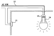
- the current LED lighting is configured by replacing the lamp with the LED lamp 14 in the lighting switch 11, lighting wiring 12 and the socket 13 used in the existing incandescent or fluorescent lamp as shown in FIG.
- Such LED lighting can control only the on / off of the LED lamp 14 using the light switch 11 used in the prior art, and cannot control the illuminance thereof.
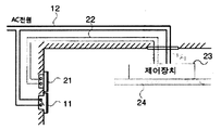
- the LED lighting capable of illuminance control includes an illuminance control switch 21, an illuminance control wiring 22, and a control device separate from the conventional illumination switch 11 and the illumination wiring 12. 23), and further comprises an LED lamp (24).
- the LED light 24 is controlled on / off using the light switch 11, and the illuminance of the LED lamp 24 is controlled using the light control switch 21. Then, the controller 23 receives the on / off control of the illumination switch 11 and the illumination control of the illumination control switch 21 to drive the LED lamp 24.
- Such conventional illumination controllable LED lighting has a problem in that the installation is complicated and expensive because additional wiring work must be performed separately from the existing lighting wiring 12.
- the present invention has been proposed to solve the above problems, and an object of the present invention is to provide an apparatus for the user to emotionally control the lighting of the LED lamp by using an electronic switch for illumination control.
- the automatic illuminance control device of the LED lighting apparatus an electronic switch for dimming control to output a pattern signal consisting of supply or interruption of the AC input power supplied to the LED lamp ; And an LED lamp controller for analyzing the pattern signal and controlling the illuminance of the LED lamp according to the analyzed pattern signal.
- the electronic switch for illuminance control when the user emotionally controls the LED lighting by using the electronic switch for illuminance control, the electronic switch for illuminance control sends a predetermined pattern to the LED lamp control device, and the LED lamp control device inputs the pattern. Since the user can implement the emotional lighting requested and interpreted by the user, the user's emotional lighting can be easily controlled.
- FIG. 1 is a view showing a conventional LED lighting system.
- FIG. 2 is a view showing a conventional illumination controllable LED lighting system.
- FIG. 3 is a view showing a lighting system including a control device of the LED lamp to which the present invention is applied.
- FIG. 4 is a block diagram showing an automatic illuminance control device of the LED lighting apparatus according to an embodiment of the present invention.
- FIG 5 is an exemplary view of a dimming control input unit according to the present invention.
- the second component may be referred to as the first component, and similarly, the first component may also be referred to as the second component.
- Applicant of the present invention has applied for a LED lighting system that can control the on / off and illuminance of the LED lamp as a 2009-0110113 to the Korean Patent Office.
- FIG. 3 is a functional block diagram illustrating an illumination controllable LED lighting system disclosed in Patent Application No. 2009-0110113.
- the illumination controllable LED illumination system disclosed in this prior patent application consists of the illumination switch 11, the illumination wiring 12, the LED lamp control apparatus 30, and the LED lamp 24. As shown in FIG.
- the LED lamp control device 30 includes an AC / DC converter unit 31, on / off detection means for detecting on and off states of a light switch, and an on / off state of the light switch from the on / off detection means.
- a dimming judging means for outputting a dimming signal by determining the snapping operation of the light switch by receiving information
- a dimming adjusting means for adjusting the illuminance of an LED lamp when a dimming signal is input from the dimming judging means
- a power holding circuit unit 42 for supplying driving power to the LED lamp during a snapping operation, and receiving off state information of the light switch from the on / off detecting means, when the off state of the light switch exceeds a threshold time.
- power off means for turning off the LED lamp.
- the lighting switch 11 is connected in series to the AC power through the lighting wiring 12 to supply or cut off the AC power to the LED lamp 24.
- the LED lamp controller 30 controls the dimming control. Recognize it as a signal.
- the on / off detecting means includes a zero cross detector unit 32, an undetected counter unit 33, and a clock 34.
- the dimming determination means includes a storage unit 41, a first comparator 39 and a dimming determination unit 37.
- the power-off means includes a storage 41, a second comparator 40 and a power-off judging 38.
- the dimming adjusting means includes a dimming step counter unit 36 and a dimming adjusting unit 35.
- the LED lamp 24 is turned on at the maximum brightness when the user turns on the light switch 11.
- the LED lamp 24 is turned on (on)
- the lighting switch 11 is turned off (off) for a short time (dimming threshold time) and turned on (on)
- the illumination of the LED lamp is adjusted by one step. If the user stops working at the desired brightness, the state is maintained. If a certain time elapses after the user turns off the light switch, all operations are reset and the LED lamp is turned off.
- the user in order for the user to dim the illumination step by step, the user should turn off the light switch 11 for a while. At this time, the off time should be longer than the dimming threshold time and shorter than the power off determination time. If the off time is shorter than the dimming threshold time, the dimming control is not performed. If the off time is longer than the power off determination time, the LED lamp is turned off.
- Dimming control of the LED lamp using the light switch 11 is difficult to use the dimming function because the user has to snap longer than the dimming threshold time and shorter than the power off determination time. In addition, the user can only dimm the illuminance step by step and cannot control the emotional lighting.
- the present invention is an improved technology of the prior patent application No. 2009-0110113, which allows the user to emotionally control the illuminance and color temperature of the LED lamp and adds a dimming control electronic switch for outputting a pattern according to the user's sensitivity control, LED
- the lamp controller is configured to interpret the pattern to control the LED lamp.
- the emotional control means that the intensity of the warm tone or cool tone is adjusted, or a predetermined mode (one of the repair mode, the reading mode, the rest mode and the sleep mode) is selected to control the LED lamp. It means controlling the illuminance and color temperature.
- FIG. 4 is a block diagram showing an automatic illuminance control device of the LED lighting apparatus according to an embodiment of the present invention.
- the automatic illuminance control device of the LED lighting apparatus includes an electronic switch 410 for dimming control that outputs a pattern signal according to a user's operation, and receives and interprets the pattern signal, and the LED lamp 24 according to the pattern signal. It is roughly divided into the LED lamp control device 420 to adjust and control the.
- the dimming control electronic switch 410 detects an operation state of the dimming control input unit 411 including an emotion control item manipulated by a user and the dimming control input unit 411 by a user, and outputs a pattern signal accordingly.
- Electronic control to switch between the AC input power and the LED lamp control unit 420 according to the control unit 412 and the pattern signal output from the control unit 412 to transmit the pattern signal to the LED lamp control unit 420
- the switch 413 and a power supply unit 414 for generating a driving power from the AC input power supply to the internal components of the dimming control electronic switch 410.
- the controller 412 displays the current LED lamp on / off state, dimming level, emotional lighting state, and the like on the display unit 415.
- the dimming control electronic switch 410 may be implemented as a 3-wire switch or a 2-wire clockcon switch.
- the dimming control input unit 411 includes a warm tone control switch 51 for up / down control of warm tones and a cool tone control switch for up / down control of cool tones. 52) and an on / off switch 53 for on / off control of the LED lamp.
- the LED lamp control device 420 includes an AC / DC converter unit 421 for converting AC input power into DC power, a zero potential detector 422 for detecting zero potential from the AC input power, and a pattern signal.
- the pattern storage unit 423 for storing the LED lamp control information, and recognizes the AC input power supply section and the AC input power cutoff section from the detected zero potential information to receive a pulse signal input from the dimming control electronic switch 410
- a control unit 424 for analyzing and applying the analyzed pulse signal to the pattern storage unit 423 to query the LED lamp control information corresponding to the analyzed pulse signal and to output the LED lamp control signal according to the LED lamp control information. And controlling the supply amount of DC power between the AC / DC converter unit 421 and the LED lamp 24 according to the LED lamp control signal.
- Dimming control unit for adjusting the degree 425 and the power holding circuit unit for supplying the driving power to each component of the LED lamp control device 420 while the dimming control electronic switch 410 cuts off the AC input power ( 426).
- the zero potential detector 422 detects a point where the AC input power becomes zero potential. That is, the zero potential detector 422 becomes a non-active level (high or low) when the AC input power is not zero potential, and becomes an active level (low or high) when the AC input power becomes zero potential. While the AC input power is normally supplied, it detects the zero potential intermittently and periodically, and then transitions from the non-active level to the active level periodically, and continuously detects the zero potential and maintains the active level while the AC input power is cut off. . The zero potential detector 422 inputs the zero potential detection signal to the controller 424.
- the controller 424 recognizes the AC input power supply section in which the AC input power is normally input, and the zero potential detection signal maintains the active level. If the AC input power is cut off, it is recognized as the AC input power cutoff section. The pattern signal is recognized from the combination or the holding time of the AC input power supply section and the AC input power cutoff section.
- Electronic switch 413 may be configured as a relay or a triac.
- the dimming control input unit 411 may be implemented as a remote control receiver (not shown) to adjust the dimming degree of the LED lamp using the remote control, or further include a remote control receiver (not shown) in addition to the dimming control input unit 411. To adjust the dimming level of the LED lamp.
- the operating method of the automatic illumination control device of the LED lighting apparatus according to the present invention is as follows.
- the controller 412 When the user operates the on / off switch 53 of the dimming control input unit 411 and switches on, the controller 412 recognizes this and drives the electronic switch 413 so that the AC input power is the LED lamp control device 420. To be supplied.
- the zero potential detector 422 When the AC input power is normally supplied, the zero potential detector 422 outputs a zero potential detection signal that maintains the non-active level and then transitions to the active level intermittently and periodically, and the control unit 424 receives the AC from the zero potential detection signal.
- the DC power of the AC / DC converter unit 421 is supplied to the LED lamp 24.
- the controller 412 controls the sensitivity. Recognize and generate pattern signal according to the emotional lighting control.
- the pattern signal is a signal formed by supplying / blocking AC input power, and the controller 412 controls the electronic switch 413 according to the pattern signal to supply or supply AC input power supplied to the LED lamp control device 420. Block it.
- the control unit 424 When the AC input power supplied to the LED lamp control device 420 is cut off, since the zero potential detector 422 maintains the zero potential detection signal at the active level, the control unit 424 receives the AC input from the zero potential detection signal. Know the power off section. On the other hand, when AC input power is again supplied to the LED lamp control device 420 according to the pattern signal, since the zero potential detector 422 outputs a zero potential detection signal that periodically transitions from the non-active level to the active level, The controller 424 recognizes the AC input power supply section from the zero potential detection signal.
- the control unit recognizes the pattern signal output from the dimming control electronic switch 410 from the holding time or combination of the AC input power cutoff section and the AC input power supply section, and applies the recognized pattern signal to the pattern storage unit 423.
- the LED lamp control information is inquired, and the dimming control unit 425 is controlled according to the inquired LED lamp control information to control the illumination of the LED lamp. For example, when the user increases the worm tone, the dimming control electronic switch 410 outputs a pattern signal accordingly, and the LED lamp controller 420 interprets the pattern signal to brightly control the illumination of the LED lamp for increasing the worm tone. .
Landscapes
- Engineering & Computer Science (AREA)
- Computer Networks & Wireless Communication (AREA)
- Circuit Arrangement For Electric Light Sources In General (AREA)
Abstract
본 발명은 엘이디 램프의 조도를 조절하기 위한 조도 제어용 전자식 스위치를 이용하여 엘이디 조명을 감성적으로 제어할 수 있는 조도 자동 제어장치에 관한 것이다. 본 발명에 따른 엘이디 조명 장치의 조도 자동 제어장치는 엘이디 램프에 공급되는 AC 입력전원의 공급 또는 차단으로 이루어진 패턴 신호를 출력하는 디밍 제어용 전자스위치와, 상기 패턴 신호를 해석하여, 해석된 패턴 신호에 따라 상기 엘이디 램프의 조도를 제어하는 엘이디 램프 제어장치를 포함한다.
Description
본 발명은 조도 자동 제어장치에 관한 것으로서, 보다 상세하게는 엘이디 램프에 사용하기 위한 조도 자동 제어장치에 관한 것이다.
종래에 조명 장치로는 백열등과 형광등이 주로 사용되었다. 그러나 백열등과 형광등은 조명 효율에 비해 전력 소모가 심한 편으로서, 세계 조명 기구의 연간 소비전력에서 약 2조 1000억㎾h를 사용하고 있다. 이는 전체 전력의 12 ~ 15%에 해당하는 것으로서, 연간 17억톤의 CO2를 배출하고 있다. 또한, 형광등은 수은을 사용하여 제조되고, 램프의 수명이 짧아서 자주 교체하여야 하기 때문에 제대로 수거하여 폐기하지 못할 경우 환경오염 문제도 심각하게 대두된다. 이러한 문제들로 인해 최근에는 일부 국가에서 백열등 및 형광등 판매 금지안이 확정되는 등 전 세계적으로 환경 규제가 강화되고 있는 실정이다.
이에 최근에 에너지 절감효과가 뛰어나고 친환경적인 엘이디(light-emitting diode)를 이용한 조명이 각광받고 있다. 이 엘이디 조명은 수명이 길고, 휘도가 높으며, 소비전력이 작아서 에너지가 절감되는 효과가 있다. 만일 국내 조명의 30%를 2015년까지 엘이디 조명으로 교체할 경우 매년 약 160억㎾h의 전력 절감 효과와 약 680만톤의 CO2를 저감하는 효과가 있는 등 그 우수함은 널리 공지되어 있다.
또한, 엘이디 램프는 전통조명 중 백열등, 할로겐등으로 구현되었던 다운라이트 조명(조도 조절이 가능한 조명)을 대체하기 위한 수단으로 여겨지고 있다.
현재 엘이디 조명은 도 1에 도시된 바와 같이 기존 백열등이나 형광등에서 사용된 조명 스위치(11), 조명 배선(12) 및 소켓(13)에 램프를 엘이디 램프(14)로 교체하여 구성된다. 이러한 엘이디 조명은 기존에 사용되던 조명 스위치(11)를 이용하여 엘이디 램프(14)의 온/오프만을 제어할 수 있고 그 조도를 제어할 수는 없다.
이 때문에 조도 제어 가능한 엘이디 조명은 도 2에 도시된 바와 같이 기존의 조명 스위치(11) 및 조명 배선(12)과는 별개의 조도제어스위치(21)와, 조도제어배선(22), 제어장치(23), 엘이디 램프(24)를 더 포함하여 이루어진다.
즉, 조명 스위치(11)를 이용하여 엘이디 조명(24)을 온/오프 조절하고, 조도제어스위치(21)를 이용하여 엘이디 램프(24)의 조도를 조절한다. 그러면, 제어장치(23)가 조명 스위치(11)의 온/오프 제어 및 조도제어스위치(21)의 조도 제어를 입력받아 엘이디 램프(24)를 구동한다.
이러한 종래의 조도 제어 가능한 엘이디 조명은 기존의 조명 배선(12)과는 별개로 추가 배선 공사를 하여야 하기 때문에 설치가 복잡하고 비용이 많이 소모되는 문제점이 있다.
본 발명은 상기한 바와 같은 문제점을 해결하기 위하여 제안된 것으로, 사용자가 조도 제어용 전자식 스위치를 이용하여 감성적으로 엘이디 램프의 조명을 제어하는 장치를 제공하는데 그 목적이 있다.
상기와 같은 목적을 달성하기 위해, 본 발명의 일실시예에 따른 엘이디 조명 장치의 조도 자동 제어장치는, 엘이디 램프에 공급되는 AC 입력전원의 공급 또는 차단으로 이루어진 패턴 신호를 출력하는 디밍 제어용 전자스위치; 및 상기 패턴 신호를 해석하여, 해석된 패턴 신호에 따라 상기 엘이디 램프의 조도를 제어하는 엘이디 램프 제어장치를 포함한다.
상기와 같은 본 발명은, 사용자가 조도 제어용 전자스위치를 이용하여 엘이디 조명을 감성적으로 제어 요청하면 조도 제어용 전자스위치는 기설정된 패턴을 엘이디 램프 제어장치에게 송출하고, 엘이디 램프 제어장치가 그 패턴을 입력받아 해석하여 사용자가 요청한 감성 조명을 구현할 수 있기 때문에 사용자의 감성조명 제어 용이성이 증대되는 효과가 있다.
도 1은 종래의 엘이디 조명 시스템을 도시한 도면이다
도 2는 종래의 조도 제어 가능 엘이디 조명 시스템을 도시한 도면이다
도 3은 본 발명이 적용되는 엘이디 램프의 제어장치를 포함한 조명 시스템을 도시한 도면이다.
도 4는 본 발명의 한 실시예에 따른 엘이디 조명 장치의 조도 자동 제어장치를 도시한 구성도이다.
도 5는 본 발명에 따른 디밍조절입력부의 예시도이다.
본 발명은 다양한 변경을 가할 수 있고 여러 가지 실시예를 가질 수 있는 바, 특정 실시예들을 도면에 예시하고 상세한 설명에 상세하게 설명하고자 한다.
그러나, 이는 본 발명을 특정한 실시 형태에 대해 한정하려는 것이 아니며, 본 발명의 사상 및 기술 범위에 포함되는 모든 변경, 균등물 내지 대체물을 포함하는 것으로 이해되어야 한다.
제1, 제2 등과 같이 서수를 포함하는 용어는 다양한 구성요소들을 설명하는데 사용될 수 있지만, 상기 구성요소들은 상기 용어들에 의해 한정되지는 않는다.
상기 용어들은 하나의 구성요소를 다른 구성요소로부터 구별하는 목적으로만 사용된다. 예를 들어, 본 발명의 권리 범위를 벗어나지 않으면서 제2 구성요소는 제1 구성요소로 명명될 수 있고, 유사하게 제1 구성요소도 제2 구성요소로 명명될 수 있다.
어떤 구성요소가 다른 구성요소에 "연결되어" 있다거나 "접속되어" 있다고 언급될 때에는, 그 다른 구성요소에 직접적으로 연결되어 있거나 또는 접속되어 있을 수도 있지만, 중간에 다른 구성요소가 존재할 수도 있다고 이해되어야 할 것이다. 반면에, 어떤 구성요소가 다른 구성요소에 "직접 연결되어" 있다거나 "직접 접속되어" 있다고 언급된 때에는, 중간에 다른 구성요소가 존재하지 않는 것으로 이해되어야 할 것이다.
본 출원에서 사용한 용어는 단지 특정한 실시예를 설명하기 위해 사용된 것으로, 본 발명을 한정하려는 의도가 아니다. 단수의 표현은 문맥상 명백하게 다르게 뜻하지 않는 한, 복수의 표현을 포함한다.
본 출원에서, "포함한다" 또는 "가지다" 등의 용어는 명세서상에 기재된 특징, 숫자, 단계, 동작, 구성요소, 부품 또는 이들을 조합한 것이 존재함을 지정하려는 것이지, 하나 또는 그 이상의 다른 특징들이나 숫자, 단계, 동작, 구성요소, 부품 또는 이들을 조합한 것들의 존재 또는 부가 가능성을 미리 배제하지 않는 것으로 이해되어야 한다.
또한 본 출원에서 첨부된 도면은 설명의 편의를 위하여 확대 또는 축소하여 도시된 것으로 이해되어야 한다.
이하, 첨부된 도면을 참조하여 본 발명의 한 실시예에 따른 엘이디 조명 장치의 조도 자동 제어장치를 보다 상세하게 설명한다.
본 발명의 출원인은 엘이디 램프의 온/오프 및 조도를 제어할 수 있는 엘이디 조명 시스템을 대한민국 특허청에 제2009-0110113호로서 특허출원하였다.
도 3은 특허출원 제2009-0110113호에 개시된 조도 조절 가능 엘이디 조명 시스템을 도시한 기능 블록도이다. 이 선행특허출원에 개시된 조도 조절 가능 엘이디 조명 시스템은, 조명스위치(11), 조명 배선(12), 엘이디 램프 제어장치(30) 및 엘이디 램프(24)로 이루어진다.
엘이디 램프 제어장치(30)는 교류/직류컨버터부(31)와, 조명스위치의 온 및 오프 상태를 검출하는 온/오프검출수단과, 상기 온/오프검출수단으로부터 상기 조명스위치의 온/오프 상태 정보를 입력받아 상기 조명스위치의 스냅핑 동작을 판단하여 디밍 신호를 출력하는 디밍판단수단과, 상기 디밍판단수단으로부터 디밍 신호가 입력되면 엘이디 램프의 조도를 조절하는 디밍조절수단과, 상기 조명스위치의 스냅핑 동작시 상기 엘이디 램프에 구동전원을 공급하는 전원홀딩회로부(42)와, 상기 온/오프검출수단으로부터 상기 조명스위치의 오프 상태 정보를 입력받아 상기 조명스위치의 오프 상태가 임계 시간을 초과하면 상기 엘이디 램프를 오프하는 파워오프수단을 포함한다.
조명 스위치(11)는 조명 배선(12)을 통해 AC전원에 직렬로 연결되어 엘이디 램프(24)에 AC전원을 공급 또는 차단한다. 사용자가 조명 스위치(11)를 온 상태에서 잠시 껐다가 다시 켜면, 즉, 온 상태에서 잠시 오프 후 다시 온하면(이를 스냅핑(snapping)이라 한다), 엘이디 램프 제어장치(30)는 이를 디밍 제어신호로 인식한다.
온/오프검출수단은 제로크로스디텍터부(32)와 미검출카운터부(33)와 클럭(34)을 포함한다. 디밍판단수단은 저장부(41)와 제1비교기(39)와 디밍 판정부(37)을 포함한다. 파워오프수단은 저장부(41)와 제2비교기(40)와 파워오프판정부(38)를 포함한다. 상기 디밍조절수단은 디밍단계카운터부(36)와 디밍조절부(35)를 포함한다. 엘이디 램프 제어장치(30)의 상세한 구성 설명 및 동작 설명은 선행 특허출원 제2009-0110113호의 출원 명세서를 참조한다.
선행 특허출원 제2009-0110113호에 개시된 조도 조절 가능 엘이디 조명 시스템은, 사용자가 조명 스위치(11)를 온하면 엘이디램프(24)는 최대 밝기로 켜진다. 이렇게 엘이디램프(24)가 켜진(온) 상태에서 조명 스위치(11)를 잠시(디밍임계시간)동안 껐다(오프)가 켜면(온), 엘이디램프의 조도가 한 단계씩 낮아지도록 조절한다. 사용자가 원하는 밝기에서 작동을 중지시키면 그 상태를 유지한다. 만약 사용자가 조명 스위치를 오프한 후 일정 시간이 경과하면, 모든 동작이 리셋되면서 엘이디램프를 오프시킨다.
즉, 선행 특허출원 제2009-0110113호에 개시된 조도 조절 가능 엘이디 조명 시스템은, 사용자가 조도를 한 단계씩 디밍하려면 조명 스위치(11)를 잠시동안 오프한 후 온해야 한다. 이때, 오프 시간은 디밍임계시간보다는 길어야 하고, 파워오프판정시간보다는 짧아야 한다. 만약, 오프 시간이 디밍임계시간보다 짧으면 디밍 제어가 이루어지지 않고, 오프 시간이 파워오프판정시간보다 길면 엘이디램프가 아주 꺼져 버린다.
이러한 조명 스위치(11)를 이용한 엘이디 램프의 디밍 제어는 사용자가 디밍임계시간보다 길고 파워오프판정시간보다 짧게 스냅핑해야 하기 때문에 디밍 기능을 이용하기 어렵다. 또한, 사용자가 조도를 한 단계씩 디밍할 수 있을 뿐이며, 감성 조명 제어를 할 수 없다.
본 발명은 선행 특허출원 제2009-0110113호의 개량기술로서, 사용자가 엘이디 램프의 조도 및 색온도를 감성 제어하도록 하고 사용자의 감성 제어 사항에 따른 패턴을 출력하는 디밍 제어용 전자스위치를 추가하여 구성하고, 엘이디 램프 제어장치가 상기 패턴을 해석하여 엘이디 램프를 제어하도록 구성한다. 여기서, 감성 제어라 함은 웜톤(warm tone)의 강도 또는 쿨톤(cool tone)의 강도를 조절하거나, 기설정된 모드(수리모드, 독서모드, 휴식모드 및 취침모드 중 하나)를 선택하여 엘이디 램프의 조도 및 색온도를 제어하는 것을 의미한다.
도 4는 본 발명의 한 실시예에 따른 엘이디 조명 장치의 조도 자동 제어장치를 도시한 구성도이다.
본 발명에 따른 엘이디 조명 장치의 조도 자동 제어장치는 사용자의 조작에 따른 패턴 신호를 출력하는 디밍 제어용 전자스위치(410)와, 상기 패턴 신호를 입력받아 해석하고 상기 패턴 신호에 따라 엘이디 램프(24)를 조절 및 제어하는 엘이디 램프 제어장치(420)로 대별된다.
디밍 제어용 전자스위치(410)는 사용자에 의해 조작되는 감성 제어 항목을 포함하는 디밍조절입력부(411)와, 사용자에 의한 상기 디밍조절입력부(411)의 조작 상태를 감지하여 그에 따른 패턴 신호를 출력하는 제어부(412)와, 상기 제어부(412)에서 출력되는 패턴 신호에 따라 AC 입력전원과 엘이디 램프 제어장치(420)와의 사이를 스위칭하여 엘이디 램프 제어장치(420)에 상기 패턴 신호가 전달되도록 하는 전자식스위치(413)와, AC 입력전원으로부터 구동전원을 생성하여 디밍 제어용 전자스위치(410)의 내부 구성요소들에게 공급하는 전원부(414)를 포함한다. 제어부(412)는 현재 엘이디 램프의 온/오프 상태, 디밍 레벨, 감성 조명 상태 등을 표시부(415)에 표시한다. 이 디밍 제어용 전자스위치(410)는 3선식(wire) 스위치 또는 2선식(wire) 클락콘 스위치로 구현될 수 있다.
디밍조절입력부(411)는 도 5에 도시된 바와 같이 웜톤(warm tone)의 업/다운 제어를 위한 웜톤조절스위치(51)와, 쿨톤(cool tone)의 업/다운 제어를 위한 쿨톤조절스위치(52)와, 엘이디 램프의 온/오프(ON/OFF) 제어를 위한 온/오프스위치(53)를 포함한다.
엘이디 램프 제어장치(420)는 AC 입력전원을 직류전원으로 변환하는 교류/직류컨버터부(421)와, 상기 AC 입력전원으로부터 영전위를 검출하는 영전위디텍터부(422)와, 패턴 신호에 따른 엘이디 램프 조절 정보를 저장하는 패턴 저장부(423)와, 상기 검출된 영전위 정보로부터 AC 입력전원 공급구간과 AC 입력전원 차단구간을 인식하여 상기 디밍 제어용 전자스위치(410)로부터 입력되는 펄스 신호를 해석하고 상기 해석된 펄스 신호를 패턴 저장부(423)에 적용하여 상기 해석된 펄스 신호에 해당하는 엘이디 램프 조절 정보를 조회하고 상기 엘이디 램프 조절 정보에 따른 엘이디 램프 제어신호를 출력하는 제어부(424)와, 상기 엘이디 램프 제어신호에 따라 상기 교류/직류컨버터부(421)와 상기 엘이디 램프(24) 사이의 직류전원의 공급량을 제어하여 엘이디 램프의 조도를 조절하는 디밍조절부(425)와, 상기 디밍 제어용 전자스위치(410)가 AC 입력전원을 차단하는 동안에 상기 엘이디 램프 제어장치(420)의 각 구성요소에 구동전원을 공급하는 전원홀딩회로부(426)를 포함하여 구성된다.
영전위 디텍터부(422)는 AC 입력전원이 영전위가 되는 지점을 검출한다. 즉, 영전위 디텍터부(422)는 AC 입력전원이 영전위가 아니면 넌액티브 레벨(하이 또는 로우)이 되고, AC 입력전원이 영전위가 되면 액티브 레벨(로우 또는 하이)이 된다. AC 입력전원이 정상적으로 공급되는 동안에는 간헐적이며 주기적으로 영전위를 검출하여 넌액티브 레벨에서 주기적으로 액티브 레벨로 천이하고, AC 입력전원이 차단되는 동안에는 지속적으로 영전위를 검출하여 액티브 레벨을 지속적으로 유지한다. 영전위 디텍터부(422)는 이러한 영전위 검출신호를 제어부(424)에게 입력한다.
제어부(424)는 영전위 검출신호가 넌액티브 레벨을 유지하다가 간헐적이며 주기적으로 액티브 레벨로 천이되면 AC 입력전원이 정상적으로 입력되는 AC 입력전원 공급구간으로 인지하고, 영전위 검출신호가 액티브 레벨을 유지하면 AC 입력전원이 차단되는 AC 입력전원 차단구간으로 인지한다. 그리고, AC 입력전원 공급구간과 AC 입력전원 차단구간의 조합 또는 유지시간 등으로부터 패턴 신호를 인지한다.
전자식스위치(413)는 릴레이 또는 트라이악으로 구성될 수 있다. 디밍조절입력부(411)는 리모콘 수신부(미도시)로 구현하여 리모콘을 이용하여 엘이디 램프의 디밍 정도를 조절할 수 있도록 하거나, 디밍조절입력부(411) 이외에 리모콘 수신부(미도시)를 더 포함하여 리모콘을 이용하여 엘이디 램프의 디밍 정도를 조절할 수 있도록 한다.
본 발명에 따른 엘이디 조명 장치의 조도 자동 제어장치의 작동 방법은 다음과 같다.
사용자가 디밍조절입력부(411)의 온/오프스위치(53)를 조작하여 스위치 온하면, 제어부(412)는 이를 인지하고 전자식스위치(413)를 구동하여 AC 입력전원이 엘이디 램프 제어장치(420)에 공급되도록 한다.
AC 입력전원이 정상적으로 공급되면 영전위디텍터부(422)는 넌액티브 레벨을 유지하다가 간헐적이며 주기적으로 액티브 레벨로 천이되는 영전위 검출신호를 출력하며, 제어부(424)는 이 영전위 검출신호로부터 AC 입력전원이 정상적으로 공급되고 있음을 인지하고 디밍조절부(425)를 제어함으로써, 교류/직류컨버터부(421)의 직류전원이 엘이디 램프(24)에 공급되도록 한다.
사용자가 디밍조절입력부(411)의 감성 조명 조절을 하면, 예컨대, 웜톤조절스위치(51)의 웜톤 업 또는 다운, 또는 쿨톤조절스위치(52)의 쿨톤 업 또는 다운을 누르면, 제어부(412)를 이를 인지하고 해당 감성 조명 조절에 따른 패턴 신호를 생성한다. 이 패턴 신호는 AC 입력전원의 공급/차단으로 이루어진 신호로서, 제어부(412)는 이 패턴 신호에 따라 전자식스위치(413)를 제어하여 엘이디 램프 제어장치(420)에 공급되는 AC 입력전원을 공급 또는 차단한다.
엘이디 램프 제어장치(420)에 공급되던 AC 입력전원이 차단되면, 영전위디텍터부(422)는 영전위 검출신호를 액티브 레벨로 유지하기 때문에, 제어부(424)는 이 영전위 검출신호로부터 AC 입력전원 차단구간을 인지한다. 한편, 패턴 신호에 따라 엘이디 램프 제어장치(420)에 AC 입력전원이 다시 공급되면, 영전위디텍터부(422)는 넌액티브 레벨에서 주기적으로 액티브 레벨로 천이되는 영전위 검출신호를 출력하기 때문에, 제어부(424)는 영전위 검출신호로부터 AC 입력전원 공급구간을 인지한다.
제어부는 AC 입력전원 차단구간과 AC 입력전원 공급구간의 유지시간 또는 조합으로부터 디밍 제어용 전자스위치(410)에서 출력된 패턴 신호를 인지하고, 그 인지된 패턴 신호를 패턴저장부(423)에 적용하여 엘이디 램프 조절 정보를 조회하고, 조회된 엘이디 램프 조절 정보에 따라 디밍조절부(425)를 제어하여 엘이디 램프의 조도가 제어되도록 한다. 예컨대, 사용자가 웜톤을 증가시키면 디밍 제어용 전자스위치(410)는 이에 따른 패턴 신호를 출력하고, 엘이디 램프 제어장치(420)가 그 패턴 신호를 해석하여 웜톤 증가를 위한 엘이디 램프의 조도를 밝게 제어한다.
이상에서 본 발명에 따른 실시예들이 설명되었으나, 이는 예시적인 것에 불과하며, 당해 분야에서 통상적 지식을 가진 자라면 이로부터 다양한 변형 및 균등한 범위의 실시예가 가능하다는 점을 이해할 것이다. 따라서, 본 발명의 진정한 기술적 보호 범위는 다음의 특허청구범위에 의해서 정해져야 할 것이다.
Claims (10)
- 엘이디 램프에 공급되는 AC 입력전원의 공급 또는 차단으로 이루어진 패턴 신호를 출력하는 디밍 제어용 전자스위치; 및상기 패턴 신호를 해석하여, 해석된 패턴 신호에 따라 상기 엘이디 램프의 조도를 제어하는 엘이디 램프 제어장치를 포함하는 조도 자동 제어장치.
- 제 1 항에 있어서, 상기 디밍 제어용 전자스위치는,사용자로부터의 디밍 조절을 위한 입력을 수신하는 디밍조절입력부;상기 디밍조절입력부의 조작 상태를 감지하여 그에 따른 패턴 신호를 출력하는 제어부; 및상기 제어부에서 출력되는 패턴 신호에 따라 상기 엘이디 램프 제어장치에 공급되는 AC 입력전원을 스위칭하는 전자식스위치를 포함하는 조도 자동 제어장치.
- 제 2 항에 있어서, 상기 디밍 제어용 전자스위치는,상기 제어부의 제어에 의해, 상기 엘이디 램프의 온/오프 상태, 디밍 레벨, 감성 조명 상태를 표시하는 표시부를 더 포함하는 조도 자동 제어장치.
- 제 2 항에 있어서, 상기 전자식스위치는,릴레이 또는 트라이악인 조도 자동 제어장치.
- 제 2 항에 있어서, 상기 디밍 제어용 전자스위치는,디밍조절을 위한 리모콘 신호를 수신하는 리모콘수신부를 더 포함하는 조도 자동 제어장치.
- 제 2 항에 있어서, 상기 디밍조절입력부는,디밍조절을 위한 리모콘 신호를 수신하는 리모콘수신부인 조도 자동 제어장치.
- 제 2 항에 있어서, 상기 디밍조절입력부는,웜톤(warm tone)의 업/다운 제어를 위한 웜톤조절스위치와, 쿨톤(cool tone)의 업/다운 제어를 위한 쿨톤조절스위치와, 상기 엘이디 램프의 온/오프(ON/OFF) 제어를 위한 온/오프스위치를 포함하는 조도 자동 제어장치.
- 제 1 항에 있어서, 상기 디밍 제어용 전자스위치는,3선식(wire) 스위치 또는 2선식 클락콘 스위치로 구현되는 조도 자동 제어장치.
- 제 1 항에 있어서, 상기 엘이디 램프 제어장치는,AC 입력전원을 직류전원으로 변환하는 교류/직류컨버터부;상기 AC 입력전원으로부터 영전위를 검출하는 영전위디텍터부;기설정된 패턴 신호에 따른 엘이디 램프 조절 정보를 저장하는 패턴 저장부;상기 검출된 영전위 정보로부터 AC 입력전원 공급구간과 AC 입력전원 차단구간을 인식하여 상기 펄스 신호를 해석하고 상기 패턴 저장부로부터 상기 해석된 펄스 신호에 대응하는 엘이디 램프 조절 정보를 조회하고 상기 조회된 엘이디 램프 조절 정보에 따른 엘이디 램프 제어신호를 출력하는 제어부; 및상기 출력된 엘이디 램프 제어신호에 따라 상기 교류/직류컨버터부와 상기 엘이디 램프 사이의 직류전원의 공급량을 제어하여 상기 엘이디 램프의 조도를 조절하는 디밍조절부를 포함하는 조도 자동 제어장치.
- 제 9 항에 있어서, 상기 엘이디 램프 제어장치는,상기 디밍 제어용 전자스위치가 AC 입력전원을 공급하는 동안에 상기 직류전원을 충전하고, 상기 디밍 제어용 전자스위치가 AC 입력전원을 차단하는 동안에 상기 엘이디 램프 제어장치의 각 구성요소에 구동전원을 공급하는 전원홀딩회로부를 더 포함하는 조도 자동 제어장치.
Applications Claiming Priority (2)
| Application Number | Priority Date | Filing Date | Title |
|---|---|---|---|
| KR10-2010-0060534 | 2010-06-25 | ||
| KR1020100060534A KR20120000265A (ko) | 2010-06-25 | 2010-06-25 | 엘이디 조명 장치의 조도 자동 제어장치 |
Publications (2)
| Publication Number | Publication Date |
|---|---|
| WO2011162573A2 true WO2011162573A2 (ko) | 2011-12-29 |
| WO2011162573A3 WO2011162573A3 (ko) | 2012-02-16 |
Family
ID=45371979
Family Applications (1)
| Application Number | Title | Priority Date | Filing Date |
|---|---|---|---|
| PCT/KR2011/004635 Ceased WO2011162573A2 (ko) | 2010-06-25 | 2011-06-24 | 엘이디 조명 장치의 조도 자동 제어장치 |
Country Status (2)
| Country | Link |
|---|---|
| KR (1) | KR20120000265A (ko) |
| WO (1) | WO2011162573A2 (ko) |
Families Citing this family (1)
| Publication number | Priority date | Publication date | Assignee | Title |
|---|---|---|---|---|
| KR102092823B1 (ko) * | 2014-12-26 | 2020-04-14 | 주식회사 셀라이팅 | 조명기의 디밍 상태 확인 장치 및 방법 |
Family Cites Families (6)
| Publication number | Priority date | Publication date | Assignee | Title |
|---|---|---|---|---|
| JP3528444B2 (ja) * | 1996-07-25 | 2004-05-17 | 松下電工株式会社 | 照明装置 |
| KR100719504B1 (ko) * | 2005-08-10 | 2007-05-17 | 심현섭 | 무선 조명 제어 시스템 및 제어 방법 |
| KR100807345B1 (ko) * | 2006-04-27 | 2008-02-28 | 현대건설주식회사 | 조명 시스템 |
| KR20090046371A (ko) * | 2007-11-06 | 2009-05-11 | 심병건 | 로컬전원 주파수 동기식 순시변광램프 |
| KR20090073599A (ko) * | 2007-12-31 | 2009-07-03 | 서울반도체 주식회사 | 엘리베이터 내 조명장치 |
| KR100946202B1 (ko) * | 2009-04-02 | 2010-03-09 | 주식회사 케이디파워 | 감성 조명 시스템 |
-
2010
- 2010-06-25 KR KR1020100060534A patent/KR20120000265A/ko not_active Ceased
-
2011
- 2011-06-24 WO PCT/KR2011/004635 patent/WO2011162573A2/ko not_active Ceased
Also Published As
| Publication number | Publication date |
|---|---|
| KR20120000265A (ko) | 2012-01-02 |
| WO2011162573A3 (ko) | 2012-02-16 |
Similar Documents
| Publication | Publication Date | Title |
|---|---|---|
| WO2011162569A2 (ko) | 엘이디 조명의 조도 자동 제어장치 | |
| WO2012176947A1 (ko) | 조도 조절 가능 엘이디 조명 시스템 | |
| TWI383112B (zh) | 可節省電能消耗之照明系統及其相關方法 | |
| WO2011065725A2 (en) | Energy saving led having dimming function and mood-lighting control function | |
| KR101110174B1 (ko) | 조명제어용 무선 디밍컨버터 및 이를 포함하는 조명제어장치 | |
| KR101266279B1 (ko) | 물체의 이동에 따라 밝기가 조절되는 절전형 지하주차장 조명시스템 | |
| WO2012008800A2 (ko) | Led 조명용 통합 전원 집적 회로 | |
| CN108235531B (zh) | 具有独立电源的无线灯具驱动装置及其灯具系统 | |
| WO2015065108A1 (ko) | 스마트 led 조명장치 | |
| KR20080088016A (ko) | 엘이디를 이용한 센서등 | |
| WO2015034127A1 (ko) | 명순응 조명장치 제어 시스템 | |
| WO2011162573A2 (ko) | 엘이디 조명 장치의 조도 자동 제어장치 | |
| TWI399130B (zh) | Two - line lighting system with intelligent energy - saving control | |
| WO2010047457A1 (ko) | 엘이디 조명기구 | |
| KR101113688B1 (ko) | 조도 조절 가능 엘이디 조명 시스템 | |
| JP2010198876A (ja) | 照明制御システム | |
| JP5186271B2 (ja) | トンネル用照明システム | |
| CN205408239U (zh) | 一种多传感器智能灯控装置 | |
| CN108260250A (zh) | 一种智能的轿厢照明系统 | |
| WO2016111475A1 (ko) | 기능성 전등 스위치의 정전압 누설전류 유기장치 | |
| CN107493621A (zh) | 一种智能建筑照明节能控制系统 | |
| CN108401321B (zh) | 智能调光调色控制系统 | |
| KR101344919B1 (ko) | 인체감지 및 자동절전형 엘이디 조명장치 | |
| CN219499600U (zh) | 一种利于节能的公共照明控制电路 | |
| KR101072901B1 (ko) | 엘이디 조명장치용 스위칭 시스템의 무선통신 제어방법 |
Legal Events
| Date | Code | Title | Description |
|---|---|---|---|
| 121 | Ep: the epo has been informed by wipo that ep was designated in this application |
Ref document number: 11798408 Country of ref document: EP Kind code of ref document: A2 |
|
| NENP | Non-entry into the national phase |
Ref country code: DE |
|
| 122 | Ep: pct application non-entry in european phase |
Ref document number: 11798408 Country of ref document: EP Kind code of ref document: A2 |