WO2011158657A1 - Dispositif de filtre d'image, appareil de décodage, appareil de codage et structure de données - Google Patents
Dispositif de filtre d'image, appareil de décodage, appareil de codage et structure de données Download PDFInfo
- Publication number
- WO2011158657A1 WO2011158657A1 PCT/JP2011/062656 JP2011062656W WO2011158657A1 WO 2011158657 A1 WO2011158657 A1 WO 2011158657A1 JP 2011062656 W JP2011062656 W JP 2011062656W WO 2011158657 A1 WO2011158657 A1 WO 2011158657A1
- Authority
- WO
- WIPO (PCT)
- Prior art keywords
- image
- unit
- filter
- characteristic value
- region
- Prior art date
Links
- 238000001914 filtration Methods 0.000 claims abstract description 48
- 230000000694 effects Effects 0.000 claims description 210
- 238000000034 method Methods 0.000 claims description 155
- 238000009795 derivation Methods 0.000 claims description 21
- 230000003044 adaptive effect Effects 0.000 abstract description 214
- 238000001514 detection method Methods 0.000 abstract description 37
- 238000005192 partition Methods 0.000 description 344
- 238000012545 processing Methods 0.000 description 214
- 238000004364 calculation method Methods 0.000 description 157
- OSWPMRLSEDHDFF-UHFFFAOYSA-N methyl salicylate Chemical compound COC(=O)C1=CC=CC=C1O OSWPMRLSEDHDFF-UHFFFAOYSA-N 0.000 description 148
- 230000008569 process Effects 0.000 description 90
- 239000013598 vector Substances 0.000 description 76
- 238000013139 quantization Methods 0.000 description 60
- 238000012986 modification Methods 0.000 description 52
- 230000004048 modification Effects 0.000 description 52
- 238000010586 diagram Methods 0.000 description 47
- 230000000875 corresponding effect Effects 0.000 description 31
- 238000003708 edge detection Methods 0.000 description 25
- 238000006243 chemical reaction Methods 0.000 description 24
- 230000014509 gene expression Effects 0.000 description 22
- 230000011218 segmentation Effects 0.000 description 14
- KZSNJWFQEVHDMF-UHFFFAOYSA-N Valine Chemical compound CC(C)C(N)C(O)=O KZSNJWFQEVHDMF-UHFFFAOYSA-N 0.000 description 13
- 230000008859 change Effects 0.000 description 13
- 230000006872 improvement Effects 0.000 description 13
- 238000009825 accumulation Methods 0.000 description 10
- 238000004519 manufacturing process Methods 0.000 description 9
- 101100029969 Plasmodium berghei (strain Anka) PMVI gene Proteins 0.000 description 7
- 230000006870 function Effects 0.000 description 7
- 238000011156 evaluation Methods 0.000 description 5
- 238000011045 prefiltration Methods 0.000 description 5
- 238000012217 deletion Methods 0.000 description 4
- 230000037430 deletion Effects 0.000 description 4
- 230000002093 peripheral effect Effects 0.000 description 4
- 239000012141 concentrate Substances 0.000 description 3
- 230000007423 decrease Effects 0.000 description 3
- 238000005070 sampling Methods 0.000 description 3
- 230000009466 transformation Effects 0.000 description 3
- FFBHFFJDDLITSX-UHFFFAOYSA-N benzyl N-[2-hydroxy-4-(3-oxomorpholin-4-yl)phenyl]carbamate Chemical compound OC1=C(NC(=O)OCC2=CC=CC=C2)C=CC(=C1)N1CCOCC1=O FFBHFFJDDLITSX-UHFFFAOYSA-N 0.000 description 2
- 230000002457 bidirectional effect Effects 0.000 description 2
- 239000000203 mixture Substances 0.000 description 2
- 230000009467 reduction Effects 0.000 description 2
- 238000012935 Averaging Methods 0.000 description 1
- 101100025317 Candida albicans (strain SC5314 / ATCC MYA-2876) MVD gene Proteins 0.000 description 1
- 101150079299 MVD1 gene Proteins 0.000 description 1
- 101150020780 MVD2 gene Proteins 0.000 description 1
- 230000005540 biological transmission Effects 0.000 description 1
- 230000002596 correlated effect Effects 0.000 description 1
- 238000011161 development Methods 0.000 description 1
- 230000018109 developmental process Effects 0.000 description 1
- 239000006185 dispersion Substances 0.000 description 1
- 238000005259 measurement Methods 0.000 description 1
- 239000002689 soil Substances 0.000 description 1
Images


Classifications
-
- G—PHYSICS
- G06—COMPUTING; CALCULATING OR COUNTING
- G06T—IMAGE DATA PROCESSING OR GENERATION, IN GENERAL
- G06T5/00—Image enhancement or restoration
-
- H—ELECTRICITY
- H04—ELECTRIC COMMUNICATION TECHNIQUE
- H04N—PICTORIAL COMMUNICATION, e.g. TELEVISION
- H04N19/00—Methods or arrangements for coding, decoding, compressing or decompressing digital video signals
- H04N19/10—Methods or arrangements for coding, decoding, compressing or decompressing digital video signals using adaptive coding
- H04N19/169—Methods or arrangements for coding, decoding, compressing or decompressing digital video signals using adaptive coding characterised by the coding unit, i.e. the structural portion or semantic portion of the video signal being the object or the subject of the adaptive coding
- H04N19/17—Methods or arrangements for coding, decoding, compressing or decompressing digital video signals using adaptive coding characterised by the coding unit, i.e. the structural portion or semantic portion of the video signal being the object or the subject of the adaptive coding the unit being an image region, e.g. an object
- H04N19/176—Methods or arrangements for coding, decoding, compressing or decompressing digital video signals using adaptive coding characterised by the coding unit, i.e. the structural portion or semantic portion of the video signal being the object or the subject of the adaptive coding the unit being an image region, e.g. an object the region being a block, e.g. a macroblock
-
- G—PHYSICS
- G06—COMPUTING; CALCULATING OR COUNTING
- G06T—IMAGE DATA PROCESSING OR GENERATION, IN GENERAL
- G06T9/00—Image coding
- G06T9/004—Predictors, e.g. intraframe, interframe coding
-
- H—ELECTRICITY
- H04—ELECTRIC COMMUNICATION TECHNIQUE
- H04N—PICTORIAL COMMUNICATION, e.g. TELEVISION
- H04N19/00—Methods or arrangements for coding, decoding, compressing or decompressing digital video signals
- H04N19/10—Methods or arrangements for coding, decoding, compressing or decompressing digital video signals using adaptive coding
- H04N19/102—Methods or arrangements for coding, decoding, compressing or decompressing digital video signals using adaptive coding characterised by the element, parameter or selection affected or controlled by the adaptive coding
- H04N19/117—Filters, e.g. for pre-processing or post-processing
-
- H—ELECTRICITY
- H04—ELECTRIC COMMUNICATION TECHNIQUE
- H04N—PICTORIAL COMMUNICATION, e.g. TELEVISION
- H04N19/00—Methods or arrangements for coding, decoding, compressing or decompressing digital video signals
- H04N19/10—Methods or arrangements for coding, decoding, compressing or decompressing digital video signals using adaptive coding
- H04N19/134—Methods or arrangements for coding, decoding, compressing or decompressing digital video signals using adaptive coding characterised by the element, parameter or criterion affecting or controlling the adaptive coding
- H04N19/136—Incoming video signal characteristics or properties
- H04N19/14—Coding unit complexity, e.g. amount of activity or edge presence estimation
-
- H—ELECTRICITY
- H04—ELECTRIC COMMUNICATION TECHNIQUE
- H04N—PICTORIAL COMMUNICATION, e.g. TELEVISION
- H04N19/00—Methods or arrangements for coding, decoding, compressing or decompressing digital video signals
- H04N19/10—Methods or arrangements for coding, decoding, compressing or decompressing digital video signals using adaptive coding
- H04N19/169—Methods or arrangements for coding, decoding, compressing or decompressing digital video signals using adaptive coding characterised by the coding unit, i.e. the structural portion or semantic portion of the video signal being the object or the subject of the adaptive coding
- H04N19/17—Methods or arrangements for coding, decoding, compressing or decompressing digital video signals using adaptive coding characterised by the coding unit, i.e. the structural portion or semantic portion of the video signal being the object or the subject of the adaptive coding the unit being an image region, e.g. an object
-
- H—ELECTRICITY
- H04—ELECTRIC COMMUNICATION TECHNIQUE
- H04N—PICTORIAL COMMUNICATION, e.g. TELEVISION
- H04N19/00—Methods or arrangements for coding, decoding, compressing or decompressing digital video signals
- H04N19/50—Methods or arrangements for coding, decoding, compressing or decompressing digital video signals using predictive coding
- H04N19/593—Methods or arrangements for coding, decoding, compressing or decompressing digital video signals using predictive coding involving spatial prediction techniques
-
- H—ELECTRICITY
- H04—ELECTRIC COMMUNICATION TECHNIQUE
- H04N—PICTORIAL COMMUNICATION, e.g. TELEVISION
- H04N19/00—Methods or arrangements for coding, decoding, compressing or decompressing digital video signals
- H04N19/70—Methods or arrangements for coding, decoding, compressing or decompressing digital video signals characterised by syntax aspects related to video coding, e.g. related to compression standards
-
- H—ELECTRICITY
- H04—ELECTRIC COMMUNICATION TECHNIQUE
- H04N—PICTORIAL COMMUNICATION, e.g. TELEVISION
- H04N19/00—Methods or arrangements for coding, decoding, compressing or decompressing digital video signals
- H04N19/80—Details of filtering operations specially adapted for video compression, e.g. for pixel interpolation
- H04N19/82—Details of filtering operations specially adapted for video compression, e.g. for pixel interpolation involving filtering within a prediction loop
Definitions
- the present invention relates to an image filter device that performs image filtering.
- the present invention also relates to an encoding device and a decoding device provided with such an image filter.
- the present invention also relates to a data structure of encoded data decoded by such a decoding device.
- a moving image encoding device that generates encoded data by encoding the moving image, and decoding by decoding the encoded data
- a video decoding device (decoding device) that generates an image
- a specific moving picture encoding method for example, H.264 is used.
- KTA software which is a codec for joint development in AVC (Non-patent Document 1) and VCEG (Video Coding Expert Group).
- an image (picture) constituting a moving image is obtained by dividing a slice obtained by dividing an image, a macroblock obtained by dividing the slice, and a macroblock. It is managed by a hierarchical structure consisting of blocks to be encoded, and is usually encoded for each block.
- a predicted image is usually generated based on a local decoded image obtained by encoding / decoding an input image, and difference data between the predicted image and the input image is encoded. It becomes.
- methods for generating a predicted image methods called inter-screen prediction (inter prediction) and intra-screen prediction (intra prediction) are known.
- intra prediction predicted images in a corresponding frame are sequentially generated based on a locally decoded image in the same frame.
- one prediction direction is selected from prediction directions included in a predetermined prediction direction (prediction mode) group for each prediction unit (for example, block), and A prediction pixel value on the prediction target region is generated by extrapolating the pixel value of the reference pixel in the locally decoded image in the selected prediction direction.
- inter prediction by applying motion compensation using a motion vector to a reference image in a reference frame (decoded image) in which the entire frame is decoded, a predicted image in a prediction target frame is converted into a prediction unit ( For example, it is generated for each block).
- Non-Patent Document 2 and Non-Patent Document 3 the (local) decoded image is divided into a plurality of regions, and the activity (Activity) indicating the local randomness of the (local) decoded image in each region is set.
- an adaptive loop filter Adaptive Loop Filter
- adaptive filter that performs filter processing while switching the filter coefficient group for each region is disclosed.
- the filter coefficient group for each region is determined by the encoding device so as to minimize the error between the filtered image in the region and the encoding target image.
- An encoding device and a decoding device provided with such an adaptive filter generate a prediction image with reference to a filtered decoded image obtained by performing filter processing on the (local) decoded image using the adaptive filter. As a result, it is possible to improve the prediction accuracy and the encoding efficiency.
- Non-Patent Document 2 and Non-Patent Document 3 are used, the encoding efficiency is not improved or the encoding efficiency is expected to be expected. It had the problem of not improving.
- the present invention has been made on the basis of the knowledge obtained by the inventor in view of the above problems, and its purpose is to provide an image characteristic that does not improve the encoding efficiency even when the filter coefficient group is switched depending on the degree of activity.
- An object of the present invention is to realize an image filter device capable of improving the coding efficiency for a (local) decoded image, and a decoding device and a coding device including such an image filter device.
- the inventor does not switch the filter coefficient group according to the local activity level of the (local) decoded image, depending on the image characteristics of the encoding target image. It was found that the coding efficiency can be improved more effectively by switching the filter coefficient group according to the difference in local directionality of the (local) decoded image.
- an image filter device includes a pixel value of each pixel in an output image, a pixel value in a reference area determined according to the position of the pixel in the input image, and a filter coefficient group.
- directionality identifying means for identifying the directionality of the input image in each of the plurality of unit areas constituting the input image
- Classification means for classifying each unit region into any one of a plurality of unit region groups according to which of the plurality of predetermined groups the directionality of the input image belongs to
- each pixel in the output image Filter means for calculating a pixel value using a filter coefficient group optimized for a unit region group to which the unit region including the pixel belongs. It is characterized in that.
- the inventor when the directionality of the input image input to the image filter device is different for each region (unit region) constituting the input image, the filter coefficient according to the difference in directionality It has been found that by switching the group, the prediction accuracy of the predicted image generated with reference to the output image can be improved.
- the direction identification means identifies the directionality of the input image in each of a plurality of unit regions constituting the input image, and the classification means Are classified into any of a plurality of unit area groups according to which of the plurality of predetermined groups belong to, and the filter means determines the pixel value of each pixel in the output image Since the calculation is performed using the optimized filter coefficient group for the unit region group to which the unit region including the pixel belongs, when the directionality of the input image is different for each unit region, it is appropriate according to the directionality. Filter processing can be performed.
- the image filter device configured as described above, even if the input image has an image characteristic that does not improve the encoding efficiency even when the filter coefficient group is switched depending on the degree of activity, the output The prediction accuracy of the predicted image generated with reference to the image can be improved.
- the directionality of the input image in each unit region can be defined as a direction orthogonal to the local gradient direction of the input image in each unit region, for example.
- the gradient of the image is a curved surface ⁇ (x defined in a three-dimensional space having x, y, z as coordinates, where the pixel value of the pixel (x, y) is z (x, y). , Y, z (x, y))
- Nx, Ny, and Nz respectively represent the total number of pixels in the x direction, the total number of pixels in the y direction, and the maximum value that the pixel value z can take.
- the directionality of the input image in each unit region can be expressed as a direction in which the correlation between the pixel values of the input image in each unit region is higher.
- the direction identification means may be configured to directly identify the directionality of the input image in each unit region by detecting an edge of the input image, or the image filter device may perform intra-screen prediction.
- the image filter device may perform intra-screen prediction.
- predicted image generation means for generating an intra-predicted image by the above it may be configured to be indirectly identified by the direction indicated by the intra-prediction mode that is referred to when generating the intra-predicted image. It is good also as a structure identified by.
- the unit area represents each of a plurality of non-overlapping areas constituting the input image.
- the unit region is a prediction that is a unit for generating a predicted image, for example. It may be a unit (partition), may be a conversion unit that is a unit of frequency conversion, or may be other than those.
- the decoding device is a decoding device that decodes encoded data and generates a decoded image after filtering, wherein the image filter device and the predicted image in each unit region are represented by the image filter device.
- a prediction image generation unit that generates a reference image by referring to the generated output image, and the image filter device includes a prediction image generated by the prediction image generation unit, a residual image decoded from the encoded data, and It is characterized in that the decoded image obtained by adding is used as an input image, and the decoded image after filtering is generated as an output image.
- the image filter device included in the decoding device includes the prediction image generated by the prediction image generation unit and the residual decoded from the encoded data.
- a decoded image obtained by adding the difference image is used as an input image, and an output image (using a filter coefficient group optimized for each unit region group according to the directionality of the input image (decoded image)) (Decoded image after filtering) is generated, so that even if the directionality of the input image is different for each unit region, an output image suitable as a reference image for generating a predicted image is generated. can do. Therefore, according to said structure, the improvement of the prediction precision of the estimated image which the said estimated image generation means produces
- the encoding device having the configuration corresponding to the above configuration it is possible to improve the prediction accuracy of the predicted image even when the directionality of the encoding target image in each unit region is different for each unit region. Therefore, encoded data with high encoding efficiency can be generated. Moreover, according to the decoding apparatus having the above configuration, it is possible to appropriately decode such encoded data with high encoding efficiency.
- the decoding device is a decoding device that decodes encoded data and generates a decoded image after filtering, and includes the image filter device, and the image filter device corresponds to the input image.
- a decoded image obtained by adding a prediction image generated by intra prediction with reference to a reference image and a residual image decoded from the encoded data is used as an input image, and the filtered image is output as an output image.
- the decoded image is generated.
- the image filter device included in the decoding device includes a prediction image generated by intra prediction and a residual image decoded from the encoded data. Is used as an input image, and an output image (filtered) is obtained using a filter coefficient group optimized for each unit region group according to the directionality of the input image (decoded image). Therefore, even when the directionality of the input image is different for each unit region, an output image suitable as an image to be referred to for generating a predicted image is generated. Can do. Therefore, according to said structure, the improvement of the prediction precision of the estimated image which the said estimated image generation means produces
- the encoding device having the configuration corresponding to the above configuration it is possible to improve the prediction accuracy of the predicted image even when the directionality of the encoding target image in each unit region is different for each unit region. Therefore, encoded data with high encoding efficiency can be generated. Moreover, according to the decoding apparatus having the above configuration, it is possible to appropriately decode such encoded data with high encoding efficiency.
- the image filter device identifies the directionality of the input image in each unit area based on at least one of the direction indicated by the prediction parameter used in the intra prediction and the shape of each unit area.
- the directionality of the input image can be identified without performing calculations that refer to pixel values such as edge detection, so that the amount of processing for identifying the directionality is reduced and encoding efficiency is high.
- the encoded data can be decoded.
- An encoding apparatus is an encoding apparatus that generates encoded data by encoding a residual image between an encoding target image and a prediction image, the image filter device, and each unit Prediction image generation means for generating the prediction image in the region with reference to the output image generated by the image filter device, the image filter device, the prediction image generated by the prediction image generation means, A decoded image obtained by adding the residual image is used as an input image, and an output image is generated.
- the image filter apparatus included in the encoding apparatus includes a prediction image generated by the prediction image generation unit, an encoding target image, and a prediction image.
- a decoded image obtained by adding residual images is used as an input image, and an output image is generated using a filter coefficient group optimized for each unit region group in accordance with the directionality of the input image (decoded image). Therefore, even when the directionality of the input image is different for each unit region, an output image suitable as an image to be referred to for generating a predicted image can be generated. Therefore, according to said structure, the improvement of the prediction precision of the estimated image which the said estimated image generation means produces
- An encoding apparatus is an encoding apparatus that generates encoded data by encoding a residual image between an encoding target image and a predicted image, and includes the image filter device.
- the filter device generates an output image using, as an input image, a decoded image obtained by adding a prediction image generated by intra prediction with reference to a reference image corresponding to the input image and the residual image. It is what is to be done.
- the image filter device included in the decoding device includes a prediction image generated by intra prediction, a residual between an encoding target image and a prediction image. Since a decoded image obtained by adding images is used as an input image, an output image is generated using a filter coefficient group optimized for each unit region group according to the directionality of the input image (decoded image). Even when the directionality of the input image is different for each unit region, an output image suitable as an image to be referred to for generating a predicted image can be generated. Therefore, according to said structure, the improvement of the prediction precision of the estimated image which the said estimated image generation means produces
- the image filter device identifies the directionality of the input image in each unit area based on at least one of the direction indicated by the prediction parameter used in the intra prediction and the shape of each unit area.
- the directionality of the input image can be identified without performing calculations that refer to pixel values such as edge detection, so that the amount of processing for identifying the directionality is reduced and encoding efficiency is high. Encoded data can be generated.
- the pixel value of each pixel in the output image is calculated from the pixel value in the reference area determined according to the position of the pixel in the input image and the filter coefficient group.
- a data structure of encoded data referred to by an image filter device comprising: a plurality of filter coefficient groups; and directionality information associated with each of the plurality of filter coefficient groups.
- Each unit area is classified into one of a plurality of unit area groups according to which of the plurality of predetermined groups the directionality of the input image in each of the plurality of unit areas constituting the input image.
- the pixel value of each pixel in the output image is calculated using the filter coefficient group that is selected for the unit region group unit area including the pixel belongs, is characterized by.
- the encoded data according to the present invention configured as described above includes a plurality of filter coefficient groups and directionality information associated with each of the plurality of filter coefficient groups.
- the image filter device to be referenced selects a filter coefficient group optimized for each of the plurality of unit region groups from the plurality of filter coefficient groups with reference to the directionality information, and each pixel in the output image Is calculated using the filter coefficient group selected for the unit region group to which the unit region including the pixel belongs, and therefore, when the directionality of the input image is different for each unit region, the predicted image It is possible to generate a more suitable output image for generating the image. Therefore, it is possible to improve the prediction accuracy of the prediction image generated with reference to the output image generated by the image filter device according to the present invention configured as described above.
- An image filter device is an image filter device that generates an output image from an input image generated for each unit region using intra prediction, and the pixel value of each pixel in the output image
- the shape and size of each unit area is any of a plurality of predetermined groups.
- Classifying means for classifying each unit area into one of a plurality of unit area groups depending on whether it belongs, and the pixel value of each pixel in the output image is optimized for the unit area group to which the unit area including the pixel belongs
- the inventor switches the filter coefficient group for each unit region according to the shape and size difference of the unit region (prediction unit) constituting the input image generated for each unit region using intra prediction. Since a more suitable output image for generating a prediction image can be generated, the input image has an image characteristic that does not improve the encoding efficiency even if the filter coefficient group is switched depending on the degree of activity. It has also been found that the prediction accuracy of a predicted image generated with reference to the output image can be improved.
- the classification unit includes a plurality of unit regions according to which of the plurality of predetermined groups the shape and size of each unit region belong to.
- the filter means calculates the pixel value of each pixel in the output image using a filter coefficient group optimized for the unit area group to which the unit area including the pixel belongs. Therefore, even if the input image has an image characteristic that does not improve the encoding efficiency even if the filter coefficient group is switched depending on the degree of activity, the prediction accuracy of the predicted image generated with reference to the output image Can be improved.
- the image filter device includes a filter unit that operates on an input image composed of a plurality of unit regions, and a characteristic value that indicates an image characteristic of the input image in each unit region, and each of the derivation methods
- Characteristic value calculating means for calculating different first and second characteristic values, and a characteristic that divides the characteristic value area spanned by the first and second characteristic values into a plurality of characteristic value partial areas according to the characteristic value division information
- a value dividing unit wherein the filter unit sets each pixel value of the output image in each unit region for the characteristic value partial region to which the first and second characteristic values calculated for the unit region belong. It is characterized by calculating using filter coefficients.
- the image filter device configured as described above divides a characteristic value area spanned by first and second characteristic values having different derivation methods into a plurality of characteristic value partial areas according to characteristic value division information. Then, it operates on the input image in each characteristic value partial area using the filter coefficient set for the characteristic value partial area to which the first and second characteristic values calculated for the unit area belong.
- the filter processing using the filter coefficient set according to the first and second characteristic values is performed for each unit region, the first and the first input images in each unit region are processed. Even when the second characteristic value varies, it is possible to perform filter processing using an appropriate filter coefficient for each unit region. In addition, it is possible to improve the prediction accuracy of a predicted image generated by referring to the output image of the image filter device configured as described above.
- first and second characteristic values have different derivation methods, so that a two-dimensional characteristic value region is created. Any two characteristic values that can extend a two-dimensional characteristic value region can be used as the first and second characteristic values.
- the unit area represents each of a plurality of non-overlapping areas constituting the input image.
- the unit region is a prediction that is a unit for generating a predicted image, for example. It may be a unit (partition), may be a conversion unit that is a unit of frequency conversion, may be an encoding unit, or may be other than those.
- the decoding device is a decoding device that decodes encoded data and generates a decoded image after filtering, wherein the image filter device and the predicted image in each unit region are represented by the image filter device.
- a prediction image generation unit that generates a reference image by referring to the generated output image, and the image filter device includes a prediction image generated by the prediction image generation unit, a residual image decoded from the encoded data, and It is characterized in that the decoded image obtained by adding is used as an input image, and the decoded image after filtering is generated as an output image.
- the image filter device included in the decoding device includes the prediction image generated by the prediction image generation unit and the residual decoded from the encoded data.
- the decoded image obtained by adding the difference image is used as an input image, and the characteristic value portion to which the first and second characteristic values calculated for the unit region belong to the input image in each characteristic value partial region Since the output image (filtered decoded image) is generated by acting using the filter coefficient set for the region, the first and second characteristic values of the input image in each unit region vary. Even if it exists, an output image suitable as an image referred in order to generate a prediction image can be generated. Therefore, according to said structure, the improvement of the prediction precision of the estimated image which the said estimated image generation means produces
- the encoding device having a configuration corresponding to the above configuration, even if the first and second characteristic values for the encoding target image in each unit region are different for each unit region, the predicted image Therefore, it is possible to generate encoded data with high encoding efficiency. Moreover, according to the decoding apparatus having the above configuration, it is possible to appropriately decode such encoded data with high encoding efficiency.
- An encoding apparatus is an encoding apparatus that generates encoded data by encoding a residual image between an encoding target image and a prediction image, the image filter device, and each unit Prediction image generation means for generating the prediction image in the region with reference to the output image generated by the image filter device, and the image filter device includes the prediction image generated by the prediction image generation means and the prediction image generation device.
- a decoded image obtained by adding the residual image is used as an input image, and an output image is generated.
- the image filter device included in the encoding device includes the prediction image generated by the prediction image generation unit, the encoding target image, and the prediction image. And the decoded image obtained by adding the residual images to the input image, and the characteristic value to which the first and second characteristic values calculated for the unit region belong to the input image in each characteristic value partial region
- an output image decoded image after filtering
- the first and second characteristic values of the input image in each unit region vary. Even so, it is possible to generate an output image suitable as an image to be referred to for generating a predicted image. Therefore, according to said structure, the improvement of the prediction precision of the estimated image which the said estimated image generation means produces
- the data structure of the encoded data according to the present invention is a characteristic value indicating an image characteristic in each unit region of an input image composed of a plurality of unit regions, and the first and second derivation methods are different from each other.
- Characteristic value calculating means for calculating the characteristic value, characteristic value dividing means for dividing the characteristic value area spanned by the first and second characteristic values into a plurality of characteristic value partial areas, and each of the output images in each unit area Reference is made by an image filter device comprising: filter means for calculating a pixel value using a filter coefficient group set for a characteristic value partial region to which the first and second characteristic values calculated for the unit region belong
- the characteristic value division information referred to by the characteristic value dividing means, wherein the characteristic value division information specifies how to divide the characteristic value area.
- a filter coefficient used by the filter means is characterized in that it contains a filter coefficient for each of the characteristic values partial region.
- the image filter device that refers to the encoded data configured as described above has a plurality of characteristic value regions spanned by the first and second characteristic values in accordance with the characteristic value division information included in the encoded data. While dividing into characteristic value partial areas, the input image is filtered using the filter coefficient for each characteristic value partial area included in the encoded data.
- an appropriate filter process can be performed on the input image using the filter coefficient set for each characteristic value partial region. it can.
- the image filter device calculates the pixel value of each pixel in the output image from the pixel value in the reference area determined according to the position of the pixel in the input image and the filter coefficient group.
- directionality identifying means for identifying the directionality of the input image in each of the plurality of unit areas constituting the input image, and the input image in each unit area identified by the directionality identification means
- Classifying means for classifying each unit region into any of a plurality of unit region groups according to which of the plurality of predetermined groups the directionality, and the pixel value of each pixel in the output image
- Filter means for calculating using a filter coefficient group optimized for a unit area group to which the unit area including the pixel belongs.
- the image filter device According to the image filter device, appropriate filter processing can be performed according to the difference in directionality of the input image in each unit region. Therefore, according to the image filter device configured as described above, even if the input image has an image characteristic that does not improve the encoding efficiency even when the filter coefficient group is switched depending on the degree of activity, the output The prediction accuracy of the predicted image generated with reference to the image can be improved.
- An image filter device is an image filter device that generates an output image from an input image generated for each unit region using intra prediction, and the pixel value of each pixel in the output image
- the shape and size of each unit area is any of a plurality of predetermined groups.
- Classifying means for classifying each unit area into one of a plurality of unit area groups depending on whether it belongs, and the pixel value of each pixel in the output image is optimized for the unit area group to which the unit area including the pixel belongs
- the above image filter device appropriate filter processing can be performed according to the difference in shape and size of each unit region. Therefore, according to the image filter device configured as described above, even if the input image has an image characteristic that does not improve the encoding efficiency even when the filter coefficient group is switched depending on the degree of activity, the output The prediction accuracy of the predicted image generated with reference to the image can be improved.
- the image filter device includes a filter unit that operates on an input image composed of a plurality of unit regions, and a characteristic value that indicates an image characteristic of the input image in each unit region, and each of the derivation methods
- Characteristic value calculating means for calculating different first and second characteristic values, and a characteristic that divides the characteristic value area spanned by the first and second characteristic values into a plurality of characteristic value partial areas according to the characteristic value division information
- a value dividing unit wherein the filter unit sets each pixel value of the output image in each unit region for the characteristic value partial region to which the first and second characteristic values calculated for the unit region belong. Calculate using filter coefficients.
- the image filter device even when there is a variation in the first and second characteristic values of the input image in each unit region, filter processing using an appropriate filter coefficient is performed for each unit region. Can do.
- the data structure of the encoded data according to the present invention is a characteristic value indicating an image characteristic in each unit region of an input image composed of a plurality of unit regions, and the first and second derivation methods are different from each other.
- Characteristic value calculating means for calculating the characteristic value, characteristic value dividing means for dividing the characteristic value area spanned by the first and second characteristic values into a plurality of characteristic value partial areas, and each of the output images in each unit area Reference is made by an image filter device comprising: filter means for calculating a pixel value using a filter coefficient group set for a characteristic value partial region to which the first and second characteristic values calculated for the unit region belong
- the characteristic value division information referred to by the characteristic value dividing means, wherein the characteristic value division information specifies how to divide the characteristic value area.
- a filter coefficient used by the filter means includes a filter coefficient for each of the characteristic values partial region.
- the image filter apparatus that refers to the encoded data configured as described above can perform an appropriate filter process on the input image using the filter coefficient set for each characteristic value partial region.
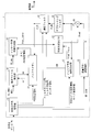
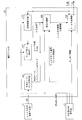
- FIG. 1 It is a block diagram which shows the structure of the moving image decoding apparatus which concerns on the 1st Embodiment of this invention. It is a figure which shows the structural example of the encoding data produced
- (F) is a prediction parameter related to the intra prediction partition among the prediction parameters included in the macroblock layer. Is a diagram showing the configuration, (g) is a diagram showing the configuration of a filter parameters included in the slice header. It is a figure for demonstrating the prediction mode which is a prediction parameter used for intra prediction, Comprising: (a) is a corresponding table
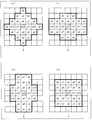
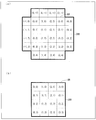
- segmentation of the 1st step is according to each value of syntax alf_second_split_flag [i0] and alf_second_split_type It is a figure which shows specifically how it is divided
- (a) is a table
- (B) is a table showing specific examples of the subdivision points PY1 to PY3 set for each value of the syntax alf_select_split_char
- (c) is a table indicating the re-set set according to the value of the syntax alf_second_split_val [k].
- 10 is a table showing specific examples of dividing points PY1 to PY3.
- Embodiment 1 (Configuration of encoded data) Prior to the description of the video encoding device 2 and the video decoding device 1 according to the present embodiment, the data structure of the encoded data # 1 generated by the video encoding device 2 and decoded by the video decoding device 1 Will be described.
- the encoded data # 1 generated by the moving image encoding device 2 and decoded by the moving image decoding device 1 includes a sequence layer, a GOP (Group Of Pictures) layer, a picture layer, a slice layer, and a macroblock layer. Has a hierarchical structure.
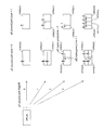
- FIG. 2 shows the structure of the encoded data for the layers below the picture layer.
- 2A to 2G show a picture layer P, a slice layer S, a macroblock layer MB, a macroblock header MBH, a prediction parameter PP of an inter prediction partition, a prediction parameter PP of an intra prediction partition, and a filter parameter FP, respectively.
- FIG. 1 shows the structure of the encoded data for the layers below the picture layer.
- 2A to 2G show a picture layer P, a slice layer S, a macroblock layer MB, a macroblock header MBH, a prediction parameter PP of an inter prediction partition, a prediction parameter PP of an intra prediction partition, and a filter parameter FP, respectively.
- the picture layer P is a set of data referred to by the video decoding device 1 in order to decode the target picture. As shown in FIG. 2A, the picture layer P includes a picture header PH and slice layers S 1 to S Ns (Ns is the total number of slice layers included in the picture layer P).
- the picture header PH includes a coding parameter group referred to by the video decoding device 1 in order to determine a decoding method of the target picture.
- the encoding mode information (entoropy_coding_mode_flag) indicating the variable length encoding mode used in encoding by the moving image encoding device 2 is an example of an encoding parameter included in the picture header PH.
- Each slice layer S included in the picture layer P is a set of data referred to by the video decoding device 1 in order to decode the target slice.
- the slice layer S includes a slice header SH and macroblock layers MB 1 to MB Nm (Nm is the total number of macroblocks included in the slice S).
- the slice header SH includes a coding parameter group that the moving image decoding apparatus 1 refers to in order to determine a decoding method of the target slice.
- Slice type specification information (slice_type) for specifying a slice type
- POC specification information (pic_order_cnt_lbs, delta_pic_order_cnt, etc.) for specifying the display order (POC: Picture Order Count) of a picture including the target slice
- POC Picture Order Count
- the weighting factor designation information pred_weight_table
- pred_weight_table that designates the weighting factor used when the moving image coding apparatus 2 performs the coding is an example of a coding parameter included in the slice header SH.
- slice types that can be specified by the slice type specification information, (1) I slice using only intra prediction at the time of encoding, and (2) P using unidirectional prediction or intra prediction at the time of encoding. Slice, (3) B-slice using unidirectional prediction, bidirectional prediction, or intra prediction at the time of encoding.
- the slice header SH includes a filter parameter FP that is referred to by the adaptive filter included in the video decoding device 1.
- the adaptive filter included in the video decoding device 1 classifies each of one or a plurality of divided regions (or partitions) included in the target slice or the target macroblock as one of a plurality of types, as will be described later.
- the filter processing is performed using different filter coefficient groups for each type.
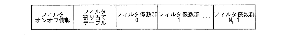
- FIG. 2G shows the data structure of the filter parameter FP. As shown in FIG.
- the said partition is a unit (prediction unit) which produces
- the said division area is an area
- the filter on / off information includes (1) region designation information for designating the size and position of the one or a plurality of divided regions in the target slice or each macroblock included in the target slice, and (2) for each divided region ( On / off information for specifying on / off of the filtering process is included for each partition).
- the filter set number is a number for specifying, for each slice, how to classify one or a plurality of divided regions (or partitions) included in the target slice or the target macroblock.
- the adaptive filter included in the moving image decoding apparatus 1 refers to the filter set number to determine how many divided regions should be classified, and which filter coefficient group is used in each type of divided region. Can be identified.
- AI NT-1 (NT is the total number of filter coefficients included in the filter coefficient group I), and (3) offset oI is included.
- filter coefficient groups with different filter numbers are used for filter processing of divided regions (or partitions) classified into different types.
- the filter coefficient group 0 and the filter coefficient group 1 are used for filter processing of a divided area classified into type A and a divided area classified into type B different from type A, respectively.
- Each macroblock layer MB included in the slice layer S is a set of data referred to by the video decoding device 1 in order to decode the target macroblock.
- the macroblock layer MB includes a skip flag SKIP, a macroblock header MBH, prediction parameters PP 1 to PP NP , and quantization prediction errors QD 1 to QD Nb .
- Np represents the number of types of partitions (prediction units) included in the target macroblock
- Nb represents the number of types of blocks (conversion units) included in the target macroblock.
- the value of the skip flag SKIP is 1, that is, when the target macroblock is a skip block, the macroblock header MBH, the prediction parameters PP 1 to PP NP , and the quantized prediction errors QD 1 to QD in that macroblock layer Nb is omitted.
- the macroblock header MBH includes an encoding parameter referred to by the video decoding device 1 in order to determine a decoding method of the target macroblock.
- macroblock type designation information MBT (mb_type) for designating the macroblock type of the target macroblock
- CBP coded_block_pattern
- quantization step Quantization parameter difference ⁇ qp (mb_qp_delta) that specifies the size of.
- the macroblock type designation information MBT includes prediction unit designation information PT and conversion unit designation information TT.
- the prediction unit designation information PT includes a partition pattern (that is, the size of each partition included in the target macroblock and a position in the target macroblock) into the partition (prediction unit) of the target macroblock, and video coding.
- the prediction method (L0 unidirectional prediction, L1 unidirectional prediction, bidirectional prediction, intra prediction, etc.) used when the apparatus 2 generates a predicted image in each partition is designated.
- the partition size is, for example, 16 ⁇ 16 pixels, 8 ⁇ 8 pixels, 4 ⁇ 4 pixels, 16 ⁇ 8 pixels, 8 ⁇ 16 pixels, 8 ⁇ 4 pixels, 4 ⁇ 8 pixels, 8 ⁇ 1 pixels, and 1 X 8 pixels can be selected.
- each partition has M ⁇ N pixels (M is an integer equal to or smaller than the number of pixels in the horizontal direction of the target macroblock, and N is an integer equal to or smaller than the number of pixels in the vertical direction of the target macroblock).
- M is an integer equal to or smaller than the number of pixels in the horizontal direction of the target macroblock
- N is an integer equal to or smaller than the number of pixels in the vertical direction of the target macroblock.
- the conversion unit designation information TT designates the division pattern (that is, the size of each block included in the target macroblock and the position in the target macroblock) into the block (conversion unit) of the target macroblock.
- Each block is 16 ⁇ 16 pixels, 8 ⁇ 8 pixels, 4 ⁇ 4 pixels, 16 ⁇ 8 pixels, 8 ⁇ 16 pixels, 8 ⁇ 4 pixels, 4 ⁇ 8 pixels, 8 ⁇ 1 pixels, and 1 ⁇ 8 pixels.
- each block has M ′ ⁇ N ′ pixels (M ′ is an integer less than or equal to the number of pixels on one side of the target macroblock, and N ′ is less than or equal to the number of pixels on the other side of the target macroblock. (Which is an integer).
- the partition when the macro block is a square area of 16 ⁇ 16 pixels is exemplified, but the present invention is not limited to this.
- a 64 ⁇ 64 pixel macroblock a 64 ⁇ 64 pixel or 32 ⁇ 32 pixel square area, or 64 ⁇ 32 pixel, 32 ⁇ 64 pixel, 32 ⁇ 16 pixel, or 16 ⁇ 32 pixel
- the rectangular area is also allowed as a partition or block.
- the quantization parameter difference ⁇ qp is a difference qp ⁇ qp ′ between the quantization parameter qp in the target macroblock and the quantization parameter qp ′ in the macroblock encoded immediately before the macroblock.
- Each quantized prediction residual QD n included in the macroblock layer MB is encoded data generated by the moving image encoding apparatus 2 performing the following processes 1 to 3 on the target block.
- Process 1 DCT transform (Discrete Cosine Transform) is performed on the prediction residual obtained by subtracting the prediction image from the encoding target image.
- Process 2 The DCT coefficient obtained in Process 1 is quantized.
- Process 3 The DCT coefficient quantized in Process 2 is variable length encoded.
- the prediction parameter PP related to the inter prediction partition in which the prediction image is generated by the inter prediction includes a reference image index RI, an estimated motion vector, as shown in FIG.
- the index PMVI and the motion vector residual MVD are included.
- the motion vector residual MVD is encoded data generated by the moving image encoding device 2 executing the following processes 4 to 6.
- Process 4 Select an encoded / decoded locally decoded image (more precisely, an image obtained by performing deblocking processing and adaptive filtering on the encoded / decoded local decoded image)
- the motion vector mv for the target partition is derived with reference to the selected encoded / decoded local decoded image (hereinafter also referred to as “reference image”).
- Process 5 An estimation method is selected, and an estimated value (hereinafter also referred to as “estimated motion vector”) pmv of the motion vector mv assigned to the target partition is derived using the selected estimation method.
- Process 6 The motion vector residual MVD obtained by subtracting the estimated motion vector pmv derived in Process 5 from the motion vector mv derived in Process 4 is encoded.
- the reference image index RI described above specifies the locally decoded image (reference image) that has been encoded / decoded selected in the process 4, and the estimated motion vector index PMVI described above is selected in the process 5.
- the estimation methods that can be selected in the processing 5 include: (1) a locally decoded image being encoded / decoded (more precisely, a region that has already been decoded in a locally decoded image being encoded / decoded).
- a median of a motion vector allocated to a partition adjacent to the target partition hereinafter also referred to as “adjacent partition” is used as an estimated motion vector pmv.
- a motion vector assigned to a partition (often referred to as a “collocated partition”) occupying the same position as the target partition is used as an estimated motion vector pmv, etc. Is mentioned.
- the prediction parameter PP related to the partition for which unidirectional prediction is performed includes one reference image index RI, one estimated motion vector index PMVI, and one motion vector residual MVD.
- the prediction parameters PP for a partition that performs bi-directional prediction include two reference image indexes RI1 and RI2, two estimated motion vector indexes PMVI1 and PMVI2, and two motion vector residuals MVD1. And MVD2.
- the prediction parameter PP related to an intra prediction partition for which a prediction image is generated by intra prediction includes a prediction index PI as shown in FIG.
- the prediction index PI is an index for designating an intra prediction method (prediction mode) for the target partition. Note that since the types of prediction modes that can be selected for the target partition differ depending on the size of the target partition, the range of values that the prediction index can take also differs depending on the size of the target partition.
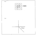
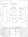
- FIG. 3A shows a correspondence table between the prediction index PI and the prediction mode for each partition size.
- prediction mode numbers 0 to 11 are assigned to each prediction mode.
- the prediction index PI is a relative number whose meaning changes depending on the partition size, whereas the prediction mode number is a unique number independent of the partition size, and each prediction mode can be distinguished from each other by the prediction mode number. (Hereinafter, the prediction mode whose prediction mode number is A will be expressed as prediction mode A).
- the prediction index PI takes one of 0, 1, 2, 3, and 4.
- prediction index 0 corresponds to prediction mode 0 (DC prediction)
- prediction index 1 corresponds to prediction mode 1 (plane prediction)
- prediction index 2 corresponds to prediction mode 2 (direction Corresponding to prediction 0)
- prediction index 3 corresponds to prediction mode 6 (direction prediction 4).
- each prediction index PI for each partition size is used. Is associated with one of the prediction modes.
- the video decoding device 1 may store the correspondence table shown in FIG. 3A in its own memory, and specify a prediction mode to be allocated to the target partition from the size of the target partition and the prediction index. it can.
- the moving picture encoding device 2 that generates the encoded data # 1 calculates an estimated value of the prediction index for the target partition based on the prediction index of the partition around the target partition, and the estimated value and the A configuration may be adopted in which a flag indicating whether or not the prediction index for the target partition is the same is included in the encoded data # 1. With such a configuration, when the estimated value and the prediction index for the target partition are the same, encoding of the prediction index for the target partition can be omitted.
- the moving picture decoding apparatus 1 includes H.264 as a part thereof. H.264 / MPEG-4. It is a decoding device including a technique adopted in AVC and KTA software.
- FIG. 1 is a block diagram showing a configuration of the moving picture decoding apparatus 1.
- the moving picture decoding apparatus 1 includes a variable length code decoding unit 13, a motion vector restoration unit 14, a buffer memory 15, an inter prediction image generation unit 16, an intra prediction image generation unit 17, and a prediction method determination unit 18. , An inverse quantization / inverse transform unit 19, an adder 20, a deblocking filter 41, and an adaptive filter 42.
- the moving picture decoding apparatus 1 is an apparatus for generating moving picture # 2 by decoding encoded data # 1.
- the variable length code decoding unit 13 decodes the prediction parameter PP related to each partition from the encoded data # 1. That is, for the inter prediction partition, the reference image index RI, the estimated motion vector index PMVI, and the motion vector residual MVD are decoded from the encoded data # 1, and these are supplied to the motion vector restoration unit 14. On the other hand, with respect to the intra prediction partition, (1) size designation information for designating the size of the partition and (2) prediction index designation information for designating the prediction index are decoded from the encoded data # 1, and this is decoded into the intra prediction image. This is supplied to the generation unit 17. Further, the variable length code decoding unit 13 decodes the macroblock type MBT from the encoded data, and supplies this to the prediction method determination unit 18 (not shown).
- variable length code decoding unit 13 decodes the quantization prediction residual QD for each block and the quantization parameter difference ⁇ qp for the macroblock including the block from the encoded data # 1, and dequantizes and decodes them. This is supplied to the inverse conversion unit 19.
- the variable length code decoding unit 13 also decodes the filter on / off information, the filter set number, and the filter coefficient group from the encoded data # 1 and supplies them to the adaptive filter 42.
- the motion vector restoration unit 14 restores the motion vector mv related to each inter prediction partition from the motion vector residual MVD related to that partition and the restored motion vector mv ′ related to another partition. Specifically, (1) the estimated motion vector pmv is derived from the restored motion vector mv ′ according to the estimation method specified by the estimated motion vector index PMVI, and (2) the derived estimated motion vector pmv and the remaining motion vector The motion vector mv is obtained by adding the difference MVD. It should be noted that the restored motion vector mv ′ relating to other partitions can be read from the buffer memory 15. The motion vector restoration unit 14 supplies the restored motion vector mv to the inter predicted image generation unit 17 together with the corresponding reference image index RI. For the inter prediction partition that performs bi-directional prediction (weighted prediction), the restored two motion vectors mv1 and mv2 are supplied to the inter prediction image generation unit 17 together with the corresponding reference image indexes RI1 and RI2.
- the inter prediction image generation unit 16 generates a motion compensation image mc related to each inter prediction partition. Specifically, using the motion vector mv supplied from the motion vector restoration unit 14, the motion compensated image mc from the filtered decoded image P_FL ′ designated by the reference image index RI also supplied from the motion vector restoration unit 14 is used. Is generated.
- the filtered decoded image P_FL ′ is obtained by performing deblocking processing by the deblocking filter 41 and adaptive filtering processing by the adaptive filter 42 on the decoded image that has already been decoded.
- the inter prediction image generation unit 16 is an image, and can read out the pixel value of each pixel constituting the filtered decoded image P_FL ′ from the buffer memory 15.
- the motion compensation image mc generated by the inter prediction image generation unit 16 is supplied to the prediction method determination unit 18 as an inter prediction image Pred_Inter.
- a motion compensated image mc1 is generated from the filtered decoded image P_FL1 ′ specified by the reference image index RI1 using the motion vector mv1.
- a motion compensated image mc2 is generated from the filtered decoded image P_FL2 ′ specified by the reference image index RI2 using the motion vector mv2, and (3) weighting between the motion compensated image mc1 and the motion compensated image mc2
- An inter predicted image Pred_Inter is generated by adding an offset value to the average.
- the intra predicted image generation unit 17 generates a predicted image Pred_Intra related to each intra prediction partition. Specifically, first, referring to the correspondence table shown in FIG. 3A recorded in its own memory, the size designation information and the prediction index designation information supplied from the variable length code decoding unit 13 are used. Based on the prediction mode, the specified prediction mode is assigned to the target partition in, for example, raster scan order. Subsequently, a predicted image Pred_Intra is generated from the decoded image P according to the prediction method indicated by the prediction mode. The intra predicted image Pred_Intra generated by the intra predicted image generation unit 17 is supplied to the prediction method determination unit 18.
- the intra predicted image generation unit 17 supplies the adaptive filter 42 with intra coding mode information IEM that is information indicating the size of the target partition and the prediction mode assigned to the target partition.
- IEM intra coding mode information
- the prediction method determination unit 18 determines whether each partition is an inter prediction partition that should perform inter prediction or an intra prediction partition that should perform intra prediction, based on the macroblock type MBT. In the former case, the inter predicted image Pred_Inter generated by the inter predicted image generation unit 16 is supplied to the adder 20 as the predicted image Pred. In the latter case, the inter predicted image generation unit 17 generates the inter predicted image Pred_Inter. The intra predicted image Pred_Intra that has been processed is supplied to the adder 20 as the predicted image Pred.
- the inverse quantization / inverse transform unit 19 (1) inversely quantizes the quantized prediction residual QD, (2) performs inverse DCT (Discrete Cosine Transform) transform on the DCT coefficient obtained by the inverse quantization, and (3) The prediction residual D obtained by the inverse DCT transform is supplied to the adder 20.
- the inverse quantization / inverse transform unit 19 derives the quantization step QP from the quantization parameter difference ⁇ qp supplied from the variable length code decoding unit 13.
- the generation of the prediction residual D by the inverse quantization / inverse transform unit 19 is performed in units of blocks (transform units).
- the adder 20 generates the decoded image P by adding the prediction image Pred supplied from the prediction method determination unit 18 and the prediction residual D supplied from the inverse quantization / inverse transformation unit 19.
- the deblocking filter 41 When the difference between the pixel values of pixels adjacent to each other via a block boundary or a macroblock boundary in the decoded image P is smaller than a predetermined threshold, the deblocking filter 41 By performing deblocking processing on the macroblock boundary, an image near the block boundary or the macroblock boundary is smoothed.
- the image that has been deblocked by the deblocking filter 41 is output to the adaptive filter 42 as a deblocked decoded image P_DB.
- the adaptive filter 42 performs a filtering process using the filter coefficient decoded from the encoded data # 1 on the deblocked decoded image P_DB supplied from the deblocking filter 41, thereby obtaining the filtered decoded image P_FL. Generate.
- the image subjected to the filter processing by the adaptive filter 42 is output to the outside as the filtered decoded image P_FL, and is associated with the POC designation information decoded from the encoded data by the variable length code decoding unit 13 in the buffer memory 15. Stored. Since a specific configuration of the adaptive filter 42 will be described later, description thereof is omitted here.
- the intra-predicted image generation unit 17 uses the pixel value of each pixel belonging to a block that has already been decoded among the pixels constituting the decoded image P, and uses the intra-prediction method specified by the prediction mode assigned to the target partition, An intra predicted image Pred_Intra for the target partition is generated.
- Each prediction mode can be distinguished from each other by a prediction mode number.
- the prediction modes DC prediction, plane prediction, direction prediction 0 to 7, TM prediction, scale prediction
- Direction predictions 0 to 7 indicate prediction methods for generating a predicted image of the target partition by extrapolating decoded pixel values around the target partition in a predetermined direction (prediction direction).
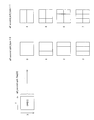
- FIG. 3B shows prediction directions corresponding to each of the direction predictions 0 to 7. As shown in FIG. 3B, the direction predictions 0 to 7 indicate the decoded pixel values around the target partition by 0 degree, 22.5 degrees, 45 degrees, 67.5 degrees, 90 degrees, respectively.
- FIG. 4A is a diagram illustrating each pixel (prediction target pixel) of the target partition, which is 4 ⁇ 4 pixels, and pixels (reference pixels) around the target partition.
- each of the prediction target pixel and the reference pixel is designated by coordinates (x, y).
- the pixel value of the prediction target pixel at the coordinates (x, y) is represented as pred4x4 [x, y], and the pixel value of the reference pixel at the coordinates (x, y) is represented as p [x, y]. Also, it is assumed that all reference pixels have been decoded.
- DC prediction prediction mode number 0
- the intra prediction image generation unit 17 takes the average value of the pixel values of the reference pixels adjacent to the upper side or the left side of the target partition, thereby calculating the pixel of the prediction target pixel. Generate a value.
- >> represents a right shift operation
- the value of a >> b is equal to the value obtained by rounding down the decimal part of the value of a ⁇ (2 to the power of b).
- This prediction mode is H.264. H.264 / MPEG-4. It corresponds to the DC prediction mode in the AVC standard.
- This prediction mode is H.264. H.264 / MPEG-4. It corresponds to the Horizontal prediction mode in the AVC standard.
- zHD 2 * yx.
- the symbol * is an arithmetic symbol representing a product (the same applies hereinafter).
- This prediction mode is H.264. H.264 / MPEG-4. It corresponds to the Horizontal down prediction mode in the AVC standard.
- Direction prediction 2 prediction mode number 4
- the intra predicted image generation unit 17 generates the pixel value of the prediction target pixel by extrapolating the pixel value of the reference pixel in a 45 degree direction.
- This prediction mode is H.264. H.264 / MPEG-4. It corresponds to the Diagonal down-right prediction mode in the AVC standard.
- Direction prediction 3 prediction mode number 5
- the intra predicted image generation unit 17 generates the pixel value of the prediction target pixel by extrapolating the pixel value of the reference pixel in the direction of 67.5 degrees. .
- Direction prediction 4 prediction mode number 6
- This prediction mode is H.264. H.264 / MPEG-4. It corresponds to the Vertical prediction mode in the AVC standard.
- Direction prediction 5 prediction mode number 7
- the intra predicted image generation unit 17 generates the pixel value of the prediction target pixel by extrapolating the pixel value of the reference pixel in the direction of 112.5 degrees. .
- This prediction mode is H.264. H.264 / MPEG-4. It corresponds to Vertical left prediction mode in the AVC standard.
- Direction prediction 6 prediction mode number 8
- the intra predicted image generation unit 17 generates the pixel value of the prediction target pixel by extrapolating the pixel value of the reference pixel in the direction of 135 degrees.
- This prediction mode is H.264. H.264 / MPEG-4. It corresponds to the Diagonal down left prediction mode in the AVC standard.
- Direction prediction 7 prediction mode number 9
- the intra predicted image generation unit 17 generates the pixel value of the prediction target pixel by extrapolating the pixel value of the reference pixel in the direction of ⁇ 22.5 degrees. To do.
- each pixel value of the target partition can be generated by a method substantially similar to the method described above.
- Plain prediction is a prediction mode that can be selected when the target partition is 16 ⁇ 16 pixels.
- the intra predicted image generation unit 17 uses the pixel value of the decoded reference pixel adjacent to the target partition to determine each pixel value of the target partition in a planar manner. Generate by prediction.
- BRS DC + planar_delta_y DC represents a pixel value generated by DC prediction.
- the intra estimated image generation part 17 is good also as a structure which calculates pixel value pred_P (x, y) of an object partition with the following formula
- Clip1Y Clip1Y (x) Clip3 (0, (1 ⁇ BitDepthY) -1, x)
- Clip3 (a, b, c) is a clip function that takes the value a when c ⁇ a, takes the value b when c> b, and takes the value c otherwise. is there.
- BitDepthY takes a value determined according to the bit depth.
- this example is H.264. H.264 / MPEG-4. This corresponds to Intra_16x16_Plane prediction mode in the AVC standard.
- TM prediction is a prediction mode that can be selected when the target partition is 4 ⁇ 4 pixels.
- the intra predicted image generation unit 17 sets a template region around the target partition, and from the decoded image P (or filtered decoded image P_FL), An area most similar to the template area is searched, and each pixel value of the area around the searched area is set as each pixel value of the target partition.
- the intra predicted image generation unit 17 performs, for example, the following processing.
- Step S101 First, as shown in FIG. 4B, an inverted L-shaped region composed of pixels adjacent to the left side or upper side of the target partition and pixels sharing the top left vertex of the target partition is set as the template region TR. .
- Step S102 Subsequently, in the decoded image P (or filtered decoded image P_FL) that has already been decoded, a reference region RR that is the same shape as the template region TR and is most similar to the template region TR is searched.
- the search of the reference region RR can be performed, for example, by evaluating the sum of absolute differences of pixel values (Sum of Absolute Difference).
- each pixel value of the 4 ⁇ 4 pixel region where the upper side and the left side are in contact with the reference region RR is set to the corresponding pixel value of the target partition.
- Scale prediction is a prediction mode that can be selected when the target partition is 16 ⁇ 16 pixels.
- the intra prediction image generation unit 17 performs (1) inverse quantization and frequency conversion on the quantization coefficient of the reduced image downsampled by the moving image encoding device. Generate image data of the reduced image, and (2) add the average value of each pixel value of the peripheral partition of the target partition and the image data of the reduced image, and then upsample, A prediction image is generated.
- the intra predicted image generation unit 17 performs, for example, the following processing.
- Step S201 frequency conversion is performed on residual data that is a difference between image data obtained by down-sampling a 16 ⁇ 16 pixel target partition to 4 ⁇ 4 pixels and an average value of each pixel value of a partition around the target partition.
- the quantized coefficient Fsr transmitted from the moving picture encoding apparatus, which is the quantized coefficient obtained by the quantization, is decoded.
- Step S202 Subsequently, the predicted value d is calculated by taking the average value of the pixel values of the partitions around the target partition.
- Step S203 Subsequently, the quantization coefficient decoded in step S201 is subjected to inverse quantization and inverse frequency conversion, thereby generating residual data B′sr of 4 ⁇ 4 pixels.
- Step S204 Subsequently, 4 ⁇ 4 pixel image data B ′s is obtained by adding the predicted value d calculated in step S202 and the 4 ⁇ 4 pixel residual data B′sr generated in step S203. Is generated.
- Step S205 the 16 ⁇ 16 pixel intra-predicted image Pred_Intra for the target partition is generated by up-sampling the 4 ⁇ 4 pixel image data B ′s generated in step S204 to 16 ⁇ 16 pixels.
- generation part with which the moving image encoder 2 mentioned later is provided performs the following processes about the object partition in which scale prediction was selected.
- Step S201 ′ First, the 4 ⁇ 4 pixel image data Bs is generated by down-sampling the 16 ⁇ 16 pixel target partition to 4 ⁇ 4 pixels.
- Step S202 ′ Subsequently, the predicted value d is calculated by taking the average value of the pixel values of the partitions around the target partition.
- Step S203 ′ Subsequently, residual data Bsr is generated by taking the difference between the image data Bs generated in step S201 ′ and the predicted value d calculated in step S202 ′.
- Step S204 ′ Subsequently, the residual data Bsr is frequency-transformed and quantized to generate a quantization coefficient.
- the generated quantization coefficient is transmitted to the video decoding device 1.
- Step S205 ′ Subsequently, residual data B′sr is generated by performing inverse frequency transform and inverse quantization on the quantization coefficient generated in step S204 ′.
- image data B ′s is generated by adding the residual data B′sr generated in step S205 ′ and the predicted value d calculated in step S202 ′.
- Step S207 ′ the image data B ′s generated in step S206 is up-sampled to 16 ⁇ 16 pixels to generate a 16 ⁇ 16 pixel intra-predicted image Pred_Intra.
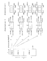
- FIG. 5 is a block diagram showing the configuration of the adaptive filter 42.
- the adaptive filter 42 includes a prediction mode / size accumulation unit 421, an edge direction detection unit 422, an activity calculation unit 423, a region classification unit 424, and a filter processing unit 425.
- the adaptive filter 42 performs a filtering process using the filter coefficient decoded from the encoded data # 1 on the deblocked decoded image P_DB supplied from the deblocking filter 41, thereby obtaining the filtered decoded image P_FL. Generate.
- the generation of the filtered decoded image P_FL may be performed in units of macroblocks, an area smaller than the macroblock may be performed as a unit, or an area larger than the macroblock may be performed as a unit.
- a description will be given by taking as an example the case where the adaptive filter 42 generates the filtered decoded image P_FL in units of macroblocks.
- the prediction mode / size accumulation unit 421 accumulates the partition size (shape and size) and the prediction mode assigned to the partition indicated by the intra coding mode information IEM supplied from the intra prediction image generation unit 17. .
- the prediction mode / size storage unit 421 can be configured to store the sizes and prediction modes for all partitions included in the target macroblock.
- the size of each partition stored in the prediction mode / size storage unit 421 and information including the prediction mode are supplied to the region classification unit 424.
- each partition and the direction indicated by the prediction mode tend to correlate with the directionality of the decoded image P (or deblocked decoded image P_DB) in each partition.
- the partition size is horizontally long, such as 8 ⁇ 1 pixels or 8 ⁇ 2 pixels
- the partition size is 1 ⁇ 8 pixels.
- the partition size is 1 ⁇ 8 pixels.
- the partition size is 1 ⁇ 8 pixels.
- the partition is vertically long, such as 2 ⁇ 8 pixels
- there is a tendency that an edge in the vertical direction is included in the partition.
- the direction prediction performed by extrapolating the decoded pixel value in a predetermined direction predetermined direction
- the size of the partition tends to correlate with the flatness of the decoded image P (or deblocked decoded image P_DB) in each partition. For example, when the partition size is small, the flatness tends to be small, and when the partition size is large, the flatness tends to be large. When the flatness is small, that is, when the activity (described later) is large, the activity is large when the partition size is small, and the activity tends to be small when the partition size is large.
- some prediction modes tend to correlate with the flatness of the decoded image P (or deblocked decoded image P_DB) in the partition in which the prediction mode is used.
- partitions predicted by plane prediction and scale prediction tend to have high flatness (low activity).
- the region classification unit 424 classifies each partition into one or a plurality of types according to the size of each partition and the prediction mode, and a filter coefficient group is included in the target macroblock. Since each divided region or partition is assigned for each type, the adaptive filter 42 is an appropriate filter according to the directionality and flatness of the decoded image P (or deblocked decoded image P_DB) in each partition. Processing can be performed.
- the edge direction detection unit 422 refers to the region designation information included in the filter on / off information supplied from the variable length code decoding unit 13, and divides the target macroblock in the deblocked decoded image P_DB into one or a plurality of divided regions. Then, edge detection is performed on the image of each divided region. In addition, an angle Theta indicating the edge direction is supplied to the region classification unit 424 for each divided region. Note that only one pixel may be included in the divided region, or a plurality of pixels may be included. In the following, the edge direction detection unit 422 performs each of the case where the divided region (target divided region) that is the target of edge detection includes only one pixel and the case where the target divided region includes a plurality of pixels. The calculation process of the angle Theta will be described.
- the edge detection unit 422 sets a 3 ⁇ 3 pixel reference region centered on the target pixel, and for each pixel in the reference region,
- the pixel values Sobel_x and Sobel_y after the Sobel filter are calculated by applying the Sobel filter matrices SFM_x and SFM_y defined by the mathematical expressions (1a) and (1b).
- Sobel_x ⁇ a + c ⁇ 2 ⁇ d + 2 ⁇ e ⁇ f + h (2a)
- Sobel_y ⁇ a ⁇ 2 ⁇ b ⁇ c + f + 2 ⁇ g + h (2b)
- edge angle an angle (hereinafter, also referred to as “edge angle”) Theta indicating the edge direction by the following mathematical formula (3).
- Theta arctan (Sobel_x / Sobel_y) (3)
- arctan represents an inverse function of the trigonometric function tan.
- the angle Theta increases clockwise and is expressed in a range from 0 degrees to 180 degrees (0 ° ⁇ Theta ⁇ 180 °).
- the edge detection unit 422 When the target divided region includes a plurality of pixels, the edge detection unit 422 first sets a 3 ⁇ 3 pixel reference region for each pixel included in the target divided region, and performs the Sobel for each pixel by the method described above. The filtered pixel values Sobel_x and Sobel_y are calculated.
- the edge detection unit 422 calculates the edge intensity ES for each pixel by the following formula (4), and uses the pixel values Sobel_x and Sobel_y after the Sobel filter for the pixel having the largest edge intensity ES. Then, the edge angle Theta is calculated by the above equation (3).
- the edge detection unit 422 determines that there is no edge for the target divided region when the edge intensity ES for all the pixels included in the target divided region is equal to or less than a predetermined threshold, and the determination result Is supplied to the region classification unit 424.
- the edge detection unit 422 may be configured to output a number (direction index) corresponding to the edge direction without calculating the angle of the edge.
- the direction index can be generated as follows by dividing the case according to the magnitude relationship between Sobel_y and Sobel_x.
- the activity calculation unit 423 refers to the region designation information included in the filter on / off information supplied from the variable length code decoding unit 13 and divides the target macroblock in the deblocked decoded image P_DB into one or a plurality of divided regions. Then, an activity ACT is calculated for the image of each divided region.
- the activity is roughly an index indicating the randomness of the image, and whether there is a large high-frequency component in the conversion coefficient obtained when the DCT conversion is performed on the region including the divided region.
- the measurement is performed based on the pixel values of adjacent pixels. The greater the difference in pixel value between adjacent pixels, the greater the activity.
- the calculated activity ACT for each divided region is supplied to the region classification unit 424.
- the activity calculating unit 423 For example, the activity ACT can be calculated by using the following formula (5a).
- Equation (5a) corresponds to the evaluation of the activity using the sum of absolute values of adjacent pixel values (Sum of Absolute Difference, SAD) as an index.
- the activity calculation unit 423 may be configured to calculate the activity ACT by using the following formula (5b).
- the sum relating to k and l in Equation (5b) indicates the sum for a rectangular region (x direction: 2K + 1 pixel, y direction: 2L + 1 pixel) centered on the pixel of coordinates (i, j). Yes.
- the sum related to k and l in Expression (5b) may be the total sum for the pixels included in the target divided region.
- Formula (5b) corresponds to the evaluation of activity using the sum of the modified Laplacians (Sum-Modified Laplacian, SML) as an index.
- the activity calculation unit 423 calculates the activity ACT for each partition included in the target macroblock.
- the area classification unit 424 includes (1) the size of each partition supplied from the prediction mode / size storage unit 421, (2) the prediction mode assigned to each partition supplied from the prediction mode / size storage unit 421, (3 ) Based on the edge angle Theta supplied from the edge direction detection unit 422 and (4) the activity ACT supplied from the activity calculation unit 423, each divided region or each partition included in the target macroblock is determined. It is classified into one or a plurality of types (hereinafter also referred to as “divided region groups”). The classification of each divided region or each partition by the region classification unit 424 is performed with reference to the filter set number decoded from the encoded data # 1 by the variable length code decoding unit 13.
- a direction index may be used instead of the edge angle Theta.
- the direction index 0 and the edge angle are set when the edge angle Theta is (0 ° ⁇ Theta ⁇ 22.5 °, or 157.5 ° ⁇ Theta ⁇ 180 °).
- edge angle Theta is A similar classification may be performed by replacing the case of (112.5 ° ⁇ Theta ⁇ 157.5 °) with the direction index 3.
- classification information indicating which type each divided region or each partition included in the target macroblock is classified is supplied to the filter processing unit 425 together with the filter coefficient group assigned to each divided region or each partition. Is done.
- the region classification unit 424 determines each partition based on the size of each partition, the prediction mode assigned to each partition, and the activity ACT of each partition. Are classified into one of a plurality of types, and when inter prediction is applied to the target macroblock, a plurality of divided regions are classified based on the edge angle in each divided region and the activity ACT of each divided region.
- the present embodiment is not limited to this.
- the configuration of the adaptive filter 42 is exemplified by the configuration shown in FIG. 5, but the present embodiment is not limited to this (hereinafter, the adaptive filter 42 shown in FIG.
- the configuration is also referred to as a basic configuration of the adaptive filter 42).
- the adaptive filter 42 includes a prediction mode size accumulation unit 421 among the prediction mode / size accumulation unit 421, the edge direction detection unit 422, and the activity calculation unit 423 in the configuration illustrated in FIG. 5.
- the configuration of the adaptive filter 42 shown in FIG. 6 is also referred to as a first modification of the adaptive filter 42).
- the adaptive filter 42 includes only the edge direction detection unit 422 among the prediction mode / size accumulation unit 421, the edge direction detection unit 422, and the activity calculation unit 423 in the configuration illustrated in FIG. 5. (Hereinafter, the configuration of the adaptive filter 42 shown in FIG. 7 is also referred to as a second modification of the adaptive filter 42).
- the adaptive filter 42 includes an edge direction detection unit 422 and a prediction mode / size storage unit 421, an edge direction detection unit 422, and an activity calculation unit 423 in the configuration shown in FIG. Only the activity calculation unit 423 may be included (hereinafter, the configuration of the adaptive filter 42 illustrated in FIG. 8 is also referred to as a third modification of the adaptive filter 42).
- the adaptive filter 42 includes a prediction mode / size storage unit among the prediction mode / size storage unit 421, the edge direction detection unit 422, and the activity calculation unit 423 in the configuration shown in FIG. Only the configuration 421 and the activity calculation unit 423 may be employed (hereinafter, the configuration of the adaptive filter 42 illustrated in FIG. 9 is also referred to as a fourth modification of the adaptive filter 42).
- the encoded data # 1 includes a flag indicating whether or not the classification process has been performed, and the area classification unit 424 refers to the flag and includes the following (classification process example 1) to (classification process example 6): Any one of the classification processes may be performed.
- FIG. 11 is a diagram for explaining the classification processing by the region classification unit 424 in this example, in which (a) is a table showing classification when the filter set number is 0, and (b) is It is a table
- the region classification unit 424 classifies all the divided regions included in the target macroblock as type 0 as illustrated in FIG.
- the region classification unit 424 divides the edge angle Theta so that the edge angle Theta satisfies (0 ° ⁇ Theta ⁇ 45 ° or 135 ° ⁇ Theta ⁇ 180 °) as shown in FIG. The region is classified as type 0, and the divided region where the edge angle Theta satisfies (45 ° ⁇ Theta ⁇ 135 °) is classified as type 1.
- the region classification unit 424 determines that the edge angle Theta is (0 ° ⁇ Theta ⁇ 22.5 °, or 157.5 ° ⁇ Theta ⁇ 180 °. ) Are classified into type 0, and divided regions satisfying the edge angle Theta (22.5 ° ⁇ Theta ⁇ 67.5 °) are classified into type 1 and the edge angle Theta is (67.5 °). A divided region satisfying ⁇ Theta ⁇ 112.5 °) is classified as type 2, and a divided region satisfying an edge angle Theta (112.5 ° ⁇ Theta ⁇ 157.5 °) is classified as type 3.
- the divided area can be classified as type 0 (see below). The same applies to the classification processing example).
- the adaptive filter 42 for performing the processing of this example the adaptive filter 42 having the basic configuration shown in FIG. 5 may be used, the second modification shown in FIG. 7 may be used, and FIG. A third modification shown in FIG. Among the (classification processing example 1) to (classification processing example 6), when only the processing of this example is performed, the configuration of the adaptive filter 42 is simplified by using the modification shown in FIG. Can do.
- the region classification unit 424 classifies each divided region included in the target macroblock based on the filter set number, the edge angle Theta of each divided region, and the activity ACT of each divided region.
- FIG. 12 is a diagram for explaining the classification processing by the region classification unit 424 in this example, in which (a) is a table showing classification when the filter set number is 0, and (b) is FIG. 4 is a table showing classification when the filter set number is 1, FIG. 5C is a table showing classification when the filter set number is 2, and FIG. 4D is a case where the filter set number is 3.
- FIG. It is a table
- the region classification unit 424 classifies all the divided regions included in the target macroblock as type 0 as illustrated in FIG.
- the region classification unit 424 classifies the divided regions whose activity ACT is equal to or less than a predetermined threshold TH as type 0, and the activity ACT Is divided into type 1 where the edge angle Theta satisfies (0 ° ⁇ Theta ⁇ 45 °, or 135 ° ⁇ Theta ⁇ 180 °), and the activity ACT is A divided region that is larger than the threshold TH and that satisfies the edge angle Theta (45 ° ⁇ Theta ⁇ 135 °) is classified as type 2.
- the region classification unit 424 classifies divided regions whose activity ACT is equal to or less than a predetermined first threshold TH1 as type 0, Divided areas whose activity ACT is larger than the second threshold TH2 that is larger than the first threshold are classified as type 5.
- the region classification unit 424 classifies the divided regions whose activity ACT is larger than the first threshold value and is equal to or smaller than the second threshold value as follows. That is, the divided area where the edge angle Theta satisfies (0 ° ⁇ Theta ⁇ 22.5 ° or 157.5 ° ⁇ Theta ⁇ 180 °) is classified as type 1, and the edge angle Theta is (22.5 ° ⁇ Theta ⁇ 67.5 °) is classified into type 2, and the divided region where edge angle Theta satisfies (67.5 ° ⁇ Theta ⁇ 112.5 °) is classified as type 3 to obtain edge angle. Divided regions in which Theta satisfies (112.5 ° ⁇ Theta ⁇ 157.5 °) are classified as type 4.
- each divided region included in the target macroblock is classified into one type, and the activity level is larger than the predetermined threshold value. Only, each divided region included in the target macroblock is classified into a plurality of types according to the directionality measured by the edge angle. This is because the merit of using the image directionality is small when the activity is small, and the merit of using the image directionality is large when the activity is large.
- the adaptive filter 42 for performing the processing of this example a filter having the basic configuration shown in FIG. 5 may be used, or a third modification shown in FIG. 8 may be used.
- the configuration of the adaptive filter 42 is simplified by using the modification shown in FIG. Can do.
- the region classification unit 424 classifies each partition included in the target macroblock based on the filter set number and the size of each partition.
- FIG. 13 is a diagram for explaining the classification processing by the region classification unit 424 in this example, where (a) is a table showing classification when the filter set number is 0, and (b) is It is a table
- (a) is a table showing classification when the filter set number is 0, and
- (c) is a table
- the region classification unit 424 classifies the 16 ⁇ 16 pixel partition and the 8 ⁇ 8 pixel partition into type 0 as illustrated in FIG.
- the pixel partition is classified as type 1
- the 8 ⁇ 1 pixel partition is classified as type 2
- the 1 ⁇ 8 pixel partition is classified as type 3.
- each partition is classified into a plurality of types according to the size and shape of each partition included in the target macroblock.
- classifying each partition according to the size of the partition depends on the activity of the image.
- classifying each partition according to the shape of the partition classifies each partition according to the directionality of the image.
- this example uses the correlation between the partition size and the activity, and the correlation between the partition shape and the directionality, without substantially referring to the activity and directionality. Classification is performed according to activity and directionality.
- the adaptive filter 42 for performing the processing of this example the adaptive filter 42 having the basic configuration shown in FIG. 5 may be used, the first modification shown in FIG. 6 may be used, and FIG. A fourth modification shown in FIG.
- FIG. 4 When at least one of the processing of this example, (classification processing example 4), and (classification processing example 5) is performed among (classification processing example 1) to (classification processing example 6), it is shown in FIG.
- the configuration of the adaptive filter 42 can be simplified.
- the region classification unit 424 classifies each partition included in the target macroblock based on the filter set number and the prediction mode assigned to each partition.
- FIG. 14 is a diagram for explaining the classification processing by the region classification unit 424 in this example, where (a) is a table showing classification when the filter set number is 0, and (b) is It is a table
- FIG. 14 is a diagram for explaining the classification processing by the region classification unit 424 in this example, where (a) is a table showing classification when the filter set number is 0, and (b) is It is a table
- the region classification unit 424 classifies all partitions included in the target macroblock as type 0 as illustrated in FIG.
- the region classification unit 424 classifies the partition to which any one of the DC prediction, the plane prediction, and the scale prediction is applied as type 0
- a partition to which direction prediction 0 is applied is classified as type 1
- a partition to which direction prediction 4 is applied is classified as type 2
- a partition to which any one of direction predictions 1 to 3 is applied is classified as type 3
- a partition to which any of the direction predictions 5 to 7 is applied is classified as type 4
- a partition to which the TM prediction is applied is classified as type 5.
- the tendency that the degree of activity decreases in a specific prediction mode is used. That is, the specific prediction mode in which the activity tends to be small and the other prediction modes are classified into different types.
- the tendency that the degree of activity decreases in the case of DC prediction, plane prediction, and scale prediction is used.
- plane prediction, and Different types may be assigned for scale prediction and DC prediction.
- DC prediction is assigned to different types, it is better to assign type 1 when the filter set number is 1 and type 5 when the filter set number is 2.
- the adaptive filter 42 for performing the processing of this example the adaptive filter 42 having the basic configuration shown in FIG. 5 may be used, the first modification shown in FIG. 6 may be used, and FIG. A fourth modification shown in FIG.
- FIG. 3 When at least one of the processing of this example, (classification processing example 3), and (classification processing example 5) is performed among (classification processing example 1) to (classification processing example 6), it is shown in FIG.
- the configuration of the adaptive filter 42 can be simplified.
- the region classification unit 424 classifies each partition included in the target macroblock based on the filter set number, the size of each partition, and the prediction mode assigned to each partition.
- FIG. 15 is a diagram for explaining the classification processing by the region classification unit 424 in this example, in which (a) is a table showing classification when the filter set number is 0, and (b) is FIG. 4 is a table showing classification when the filter set number is 1, FIG. 5C is a table showing classification when the filter set number is 2, and FIG. 4D is a case where the filter set number is 3.
- FIG. (E) is a table showing the classification when the filter set number is 4.
- the region classification unit 424 classifies the partition of 16 ⁇ 16 pixels and the partition of 8 ⁇ 8 pixels into type 0 as shown in FIG.
- the pixel partition, the 8 ⁇ 1 pixel partition, and the 1 ⁇ 8 pixel partition are classified as type 1.
- the area classification unit 424 has a size of either 16 ⁇ 16 pixels or 8 ⁇ 8 pixels, as shown in FIG.
- a partition to which any of the scale predictions is applied is classified as type 0, and the size is either 16 ⁇ 16 pixels or 8 ⁇ 8 pixels, and prediction modes other than DC prediction, plane prediction, and scale prediction are applied.
- the classified partition is classified as type 1, and the size is any of 4 ⁇ 4 pixels, 8 ⁇ 1 pixels, and 1 ⁇ 8 pixels, and any of DC prediction, plane prediction, and scale prediction is applied.
- the partition is classified as type 2 and the size is any of 4 ⁇ 4 pixels, 8 ⁇ 1 pixels, and 1 ⁇ 8 pixels, and prediction other than DC prediction, plane prediction, and scale prediction Over soil to classify the applied partition to type 3.
- the region classification unit 424 selects a partition whose size is any of 16 ⁇ 16 pixels, 8 ⁇ 8 pixels, and 4 ⁇ 4 pixels. Classify as follows. That is, a partition to which any one of DC prediction, plane prediction, and scale prediction is applied is classified into type 0, a partition to which direction prediction 0 is applied is classified into type 1, and a partition to which direction prediction 4 is applied is classified. A partition that is classified into type 2 and to which any one of direction predictions 1 to 3 and 5 to 7 is applied is classified into type 3, and a partition to which TM prediction is applied is classified into type 4.
- the region classification unit 424 converts a partition having a size of 8 ⁇ 1 pixels into a type 1 (that is, a size of 16 ⁇ 16 pixels, 8 ⁇ 8 pixels, and 4 ⁇ 4). Any of the pixels is classified into the same type as the partition to which the direction prediction 0 is applied), and the partition whose size is 1 ⁇ 8 pixels is type 2 (that is, the size is 16 ⁇ 16 pixels, 8 ⁇ 8 pixels) And the same type as the partition to which the direction prediction 4 is applied).
- the region classification unit 424 classifies a partition whose size is either 16 ⁇ 16 pixels or 8 ⁇ 8 pixels as follows. . That is, a partition to which any one of DC prediction, plane prediction, and scale prediction is applied is classified into type 0, a partition to which direction prediction 0 is applied is classified into type 1, and a partition to which direction prediction 4 is applied is classified. Partitions are classified as type 2, partitions to which any of direction predictions 1 to 3 is applied are classified as type 1, partitions to which any of direction predictions 5 to 7 are applied are classified as type 2, and TM prediction is applied. The assigned partition is classified into type 3.
- the area classification unit 424 classifies the partition having a size of 4 ⁇ 4 pixels as follows. That is, a partition to which any one of DC prediction, plane prediction, and scale prediction is applied is classified as type 4, a partition to which direction prediction 0 is applied is classified as type 5, and direction prediction 4 is applied. Partitions are classified as type 6, partitions to which any of direction predictions 1 to 3 is applied are classified as type 7, partitions to which any of direction predictions 5 to 7 are applied are classified as type 8, and TM prediction is performed. Is applied to type 9.
- the region classification unit 424 uses a partition having a size of 8 ⁇ 1 pixels as a type 5 (that is, a size of 4 ⁇ 4 pixels and direction prediction 0 is applied).
- the partition having the size of 1 ⁇ 8 pixels is classified into the type 6 (that is, the same type as the partition having the size of 4 ⁇ 4 pixels and the direction prediction 4 applied).
- this example uses both (1) the relationship between the partition size and the degree of activity, and (2) the relationship between the partition shape and the prediction mode and the directionality.
- the adaptive filter 42 for performing the processing of this example the adaptive filter 42 having the basic configuration shown in FIG. 5 may be used, the first modification shown in FIG. 6 may be used, and FIG. A fourth modification shown in FIG. FIG. 6 shows the case where at least one of the processing of this example, (classification processing example 3), and (classification processing example 4) is performed among (classification processing example 1) to (classification processing example 6).
- the configuration of the adaptive filter 42 can be simplified.
- the region classification unit 424 classifies each partition included in the target macroblock based on the filter set number, the prediction mode assigned to each partition, and the activity of each partition.
- FIG. 16 is a diagram for explaining the classification processing by the region classification unit 424 in this example, where (a) is a table showing classification when the filter set number is 0, and (b) is FIG. 4 is a table showing classification when the filter set number is 1, FIG. 5C is a table showing classification when the filter set number is 2, and FIG. 4D is a case where the filter set number is 3.
- FIG. (E) is a table showing the classification when the filter set number is 4.
- the region classification unit 424 classifies all partitions included in the target macroblock as type 0 as illustrated in FIG.
- the region classification unit 424 classifies a partition whose activity ACT is equal to or less than a predetermined threshold TH as type 0, and the activity ACT is Partitions larger than the threshold TH are classified as type 1.
- the region classification unit 424 classifies a partition whose activity ACT is equal to or less than a predetermined threshold TH as type 0, and the activity ACT is A partition that is larger than the threshold TH and to which any one of DC prediction, plane prediction, and scale prediction is applied is classified as type 1, and the activity ACT is larger than the threshold TH, Partitions to which prediction modes other than DC prediction, plane prediction, and scale prediction are applied are classified as type 2.
- the region classification unit 424 classifies the partition whose activity ACT is equal to or less than a predetermined threshold TH as type 0. Further, the region classification unit 424 classifies the partition having the activity ACT larger than the threshold TH as follows. That is, a partition to which any one of DC prediction, plane prediction, and scale prediction is applied is classified into type 1, a partition to which direction prediction 0 is applied is classified into type 2, and a partition to which direction prediction 4 is applied is classified. A partition that is classified into type 3 and to which other prediction modes are applied is classified into type 4.
- the region classification unit 424 classifies the partition whose activity ACT is equal to or less than a predetermined threshold TH as type 0. Further, the region classification unit 424 classifies the partition having the activity ACT larger than the threshold TH as follows. That is, a partition to which any one of DC prediction, plane prediction, and scale prediction is applied is classified into type 1, a partition to which direction prediction 0 is applied is classified into type 2, and a partition to which direction prediction 4 is applied is classified. Partitions classified as type 3 and applied with any one of direction predictions 1 to 3 are classified as type 4; partitions applied with any of direction predictions 5 to 7 are classified as type 5 and TM prediction is applied. The assigned partition is classified into type 6.
- this example uses both (1) the relationship between partition size and activity, and (2) the relationship between partition shape or prediction mode and directionality.
- the adaptive filter 42 for performing the processing of this example a filter having the basic configuration shown in FIG. 5 may be used, or a fourth modification shown in FIG. 9 may be used.
- the configuration of the adaptive filter 42 is simplified by using the modification shown in FIG. Can do.
- the filter processing unit 425 performs filter processing on each divided region or each partition included in the target macroblock in the deblocked decoded image P_DB using the filter coefficient group supplied from the region classification unit 424. To generate a filtered decoded image P_FL.
- the pixel value of the filter target pixel in the divided area or partition is represented as SF (x ′, y ′), and within the target macroblock or the target macroblock in the deblocked decoded image P_DB (hereinafter also referred to as “pre-filter image”)
- pre-filter image the filter processing unit 425 calculates the pixel value SF (x ′, y ′) by the following formula (6).
- the coordinates (x, y) may be the same coordinates as the coordinates (x ′, y ′), or may be different coordinates as long as they have a one-to-one correspondence.
- AI (i, j) represents a filter coefficient to be multiplied by the pixel value S (x + i, y + j) of the pre-filter image, and corresponds to the filter coefficient included in the filter coefficient group included in the encoded data # 1. is doing.
- OI represents an offset included in the filter coefficient group I.
- FIG. 17A shows an example of the filter reference region R in the present embodiment.
- the hatched pixels indicate the filter target pixels.
- a0 to a12 are filter coefficients decoded from the encoded data # 1, and represent filter coefficients assigned to each pixel included in the filter reference region R.
- the filter reference region R can be configured by pixels having an urban area distance of 3 or less from the filter target pixel, for example.
- the present embodiment is not limited to this, and the assignment of each filter coefficient to each pixel value may not have rotational symmetry.
- the filter reference region R may be a region constituted by pixels whose city distance from the coordinate (x, y) is equal to or less than Ncb in units of pixels, or the coordinates (x, y). It may be a rectangular region of Nx ⁇ Ny taps centered on, or may be a region configured to include other pixels.
- the method of assigning the filter coefficient to each pixel included in the filter reference region R and the shape of the filter reference region R may be appropriately set according to the configuration of the moving picture encoding device that generates the encoded data # 1. Good.
- the filter processing unit 425 is configured not to perform the filter processing for the divided regions and partitions designated as being off by the on / off information supplied from the variable length code decoding unit 13. be able to.
- the adaptive filter 42 sets the pixel value of each pixel in the output image (filtered decoded image P_FL) to a pixel in the reference region R that is determined according to the position of the pixel in the input image (deblocked image P_DB).
- directionality identifying means edge direction for identifying the directionality of the input image in each of a plurality of unit regions (divided regions or partitions) constituting the input image
- Each unit according to which of the plurality of predetermined groups the directionality of the input image in each unit area identified by the direction identification unit is detected by the detection unit 422 and the region classification unit 424).
- Classification means for classifying the region into any one of a plurality of unit region groups (types); The pixel value of the pixel, and a, a filter unit (filter processor 425) calculated using the optimized filter coefficient group for the unit area belongs unit area group including the pixel.
- the filter means uses the filter coefficient group optimized for the unit region group to which the unit region including the pixel belongs as the pixel value of each pixel in the output image. Therefore, when the directionality of the input image is different for each unit region, appropriate filter processing can be performed according to the directionality.
- the input image is generated with reference to the output image even if the input image has an image characteristic that does not improve the encoding efficiency even when the filter coefficient is switched depending on the degree of activity.
- the prediction accuracy of the predicted image can be improved.
- the directionality of the input image (deblocked image P_DB) in each unit region may be identified by detecting the edge of the input image by the edge direction detection unit 422, or an intra predicted image is generated. It is good also as a structure indirectly identified in the area
- the adaptive filter 42 generates an output image (filtered decoded image P_FL) from an input image (deblocked image P_DB) generated for each unit region (divided region or partition) using intra prediction.
- the image filter device for calculating the pixel value of each pixel in the output image from the pixel value of the input image in the reference area determined according to the position of the pixel and the filter coefficient group, the shape of each unit area
- a classifying means for classifying each unit region into one of a plurality of unit region groups (types) according to which of a plurality of predetermined groups the size belongs to,
- the pixel value of each pixel in the output image is calculated using a filter coefficient group optimized for the unit area group to which the unit area including the pixel belongs. That the filter means and (filter processor 425), in which is provided with a, a it can be expressed.
- the adaptive filter 42 classifies each partition into one of a plurality of groups as shown in (Classification Processing Example 3), for example, according to the shape and size of the partition. Filter processing can be performed using the filter coefficient.
- the input image is generated with reference to the output image even if the input image has an image characteristic that does not improve the encoding efficiency even when the filter coefficient is switched depending on the degree of activity.
- the prediction accuracy of the predicted image can be improved.
- the filter set number is included in the slice header SH of the encoded data # 1
- the slice header SH of the encoded data # 1 is replaced with the edge angle Theta, the prediction mode, the size of each partition, the activity ACT, and one or a plurality of filter coefficient groups (more specifically, instead of the filter set number).
- FIG. 18 is a diagram illustrating a configuration of a slice header SH ′ including a filter assignment table.
- the slice header SH ′ includes filter on / off information and filter coefficient groups 0 to Nf ⁇ 1 similarly to the slice header SH described above. Further, the slice header SH ′ includes the above-described filter assignment table instead of the filter set number included in the slice header SH.
- the filter assignment table may be, for example, a table showing the correspondence between the edge angle Theta and the filter number, or as shown in FIG. And the correspondence between the partition size and the filter number.
- the filter allocation table is not limited to that shown in FIGS. 19A to 19B, and any one of the edge direction, the partition size, the prediction mode, and the activity is associated with the filter number. Anything is acceptable.
- the area classification unit 424 included in the adaptive filter 42 refers to the filter assignment table included in the slice header SH ′, and decodes each divided area or each partition included in the target macroblock from the encoded data # 1.
- a filter coefficient group which is a filter coefficient group specified by the filter assignment table, may be assigned.
- the region classification unit 424 sets the edge angle Theta to (0 ° ⁇ Theta ⁇ 22.5 °, or 157.
- the filter coefficient group 0 is assigned to the divided area where 5 ° ⁇ Theta ⁇ 180 °), and the filter coefficient is assigned to the divided area where the edge angle Theta is (22.5 ° ⁇ Theta ⁇ 67.5 °).
- Group 2 is assigned, and the filter coefficient group 1 is assigned to the divided region where the edge angle Theta is (67.5 ° ⁇ Theta ⁇ 112.5 °), and the edge angle Theta is (112.5 ° ⁇ Theta ⁇ 157. .. (5 °), the filter coefficient group 2 is assigned to the divided area.
- the filter assignment table included in the slice header SH ′ is as shown in FIG.
- the degree of freedom to associate each of the plurality of filter coefficient groups with a different type (unit area group) is increased as compared with the case where a filter set is used.
- the degree of freedom of selection increases.
- the filter assignment table can also be regarded as information (direction information) indicating which edge angle each of the plurality of filter coefficient groups included in the encoded data # 1 is associated with.
- the filter reference region R in Expression (6) is exemplified as that shown in FIG. 17A, but the present embodiment is not limited to this.
- the filter reference region R in this embodiment for example, those shown in FIGS. 17B to 17D may be used.
- the hatched pixels indicate the filter target pixels.
- the filter reference region R illustrated in FIG. 17A is referred to as a “basic reference region”
- the filter reference region R illustrated in FIG. 17B is referred to as a “vertical reference region”.
- the filter reference region R shown in (c) is referred to as a “horizontal type reference region”
- the filter reference region R shown in FIG. 17D is referred to as an “oblique direction type reference region”.
- the basic reference area shown in FIG. 17A is a divided area or partition in which no edge exists in the target macroblock of the deblocked decoded image P_DB, or a divided area or partition whose edge strength is smaller than a predetermined value. It can be suitably used for filter processing.
- the vertical reference region has a feature that the vertical length is longer than the horizontal length. For this reason, in the object macroblock of the deblocked decoded image P_DB, it can be used suitably for the filtering process of the divided area or partition in which the vertical edge exists.
- the horizontal type reference region has a feature that the horizontal length is longer than the vertical length. For this reason, in the object macroblock of the deblocked decoded image P_DB, it can be used suitably for the filtering process of the divided area or partition where the edge in the horizontal direction exists.
- the oblique reference type area is rectangular, and therefore, in the target macroblock of the deblocked decoded image P_DB, the divided area or partition in which the oblique edge exists. It can be suitably used for filter processing.
- the filter processing unit 425 included in the adaptive filter 42 has any one of the basic reference area, the vertical direction reference area, the horizontal direction reference area, and the oblique direction reference area as the filter reference area R.
- the reference region can be selectively used. More specifically, the prediction mode / size accumulation unit 421 and the edge direction detection unit 422 are configured to supply the prediction mode of each partition and the edge angle Theta of each divided region to the filter processing unit 425, respectively.
- the filter processing unit 425 may be configured to selectively use any of the plurality of reference regions according to the edge angle of each divided region or the prediction mode of each partition.
- FIG. 20 (a) shows an example of the correspondence relationship between the edge angle and the reference area to be used.
- the filter processing unit 425 is, for example, in a divided region where the edge angle Theta satisfies (0 ° ⁇ Theta ⁇ 22.5 °, or 157.5 ° ⁇ Theta ⁇ 180 °).
- a horizontal reference area is used, and when the filter target pixel exists in a divided region where the edge angle Theta satisfies (22.5 ° ⁇ Theta ⁇ 67.5 °),
- the vertical direction type reference region is used,
- FIG. 20 (b) shows an example of the correspondence between the prediction mode and the reference area to be used.
- the filter processing unit 425 for example, when a pixel to be filtered exists in a partition whose prediction mode is any one of DC prediction, plane prediction, TM prediction, and scale prediction.
- a filter target pixel is used in the partition in which the prediction mode is directional prediction 4 using a horizontal reference region. If there is a filter target pixel in a partition that uses a vertical reference area and has a prediction mode of any one of direction predictions 1 to 3 and direction predictions 5 to 7 The reference area can be used.
- the video encoding apparatus having the same configuration as the configuration of the present modification is more suitable by selecting an optimal shape from among the shapes of the plurality of filter reference regions according to the edge angle and the prediction mode. Therefore, it is possible to improve the prediction accuracy and improve the encoding efficiency. Further, by optimizing the shape of the filter reference region according to the edge angle and the prediction mode, it is possible to perform effective filtering while reducing the total number of filter coefficient groups as much as possible.
- the moving picture decoding apparatus 1 having the configuration of the present modification can appropriately decode such encoded data with high encoding efficiency.
- the shape of the selectable reference region is not limited to that shown in FIGS. 20A to 20D, and other shapes may be used depending on the edge angle and the prediction mode. Reference regions of various shapes and sizes can be used.
- the slice header of the encoded data # 1 may be configured to include neither the filter set number nor the filter assignment table.
- the edge detection unit 422 detects the edge angle Theta in each divided region in a range of 0 ° ⁇ Theta ⁇ 180 °, but the present embodiment is limited to this. is not.
- the edge detection unit 422 may be configured to detect the edge angle Theta of each divided region in a range of 0 ° ⁇ Theta ⁇ 360 °.
- FIG. 21 shows a case where the encoded data # 1 has a configuration that does not include either the filter set number or the filter assignment table, and the edge detection unit 422 sets the angle Theta of each divided region to 0 °. It is a table
- category part 424 when it is the structure detected in the range of ⁇ Theta ⁇ 360 degrees. As shown in FIG. 21, the region classification unit 424 classifies divided regions that satisfy the edge angle Theta (0 ° ⁇ Theta ⁇ 22.5 ° or 337.5 ° ⁇ Theta ⁇ 360 °) as type 0.
- the divided region where the edge angle Theta satisfies (22.5 ° ⁇ Theta ⁇ 67.5 °) is classified as type 1, and the edge angle Theta satisfies (67.5 ° ⁇ Theta ⁇ 112.5 °).
- the divided area is classified into type 2, and the divided area where the edge angle Theta satisfies (112.5 ° ⁇ Theta ⁇ 157.5 °) is classified into type 3, and the edge angle Theta is (157.5 ° ⁇ Theta).
- ⁇ 202.5 °) is divided into type 4, and the divided region satisfying edge angle Theta (202.5 ° ⁇ Theta ⁇ 247.5 °) is classified as type 5.
- the divided area where the edge angle Theta satisfies (247.5 ° ⁇ Theta ⁇ 292.5 °) is classified as type 6, and the edge angle Theta satisfies (292.5 ° ⁇ Theta ⁇ 337.5 °).
- the divided area is classified into type 7.
- the edge angle is detected in the range of 0 ° ⁇ Theta ⁇ 360 °, and the filter coefficient group is assigned according to the detected angle, so that more effective filter processing can be performed.
- the encoded data # 1 has a configuration that includes neither the filter set number nor the filter assignment table, so that the code amount of the encoded data # 1 can be reduced.
- the region classification unit 424 is configured to classify each divided region or each partition (prediction unit) included in the target macroblock into one of a plurality of types. It is not limited to this.
- the region classification unit 424 may be configured to classify each block (conversion unit) included in the target macroblock into one of a plurality of types.
- the region classifying unit 424 assigns each block to a plurality of types according to the size, prediction mode, edge angle, and activity ACT of each block included in the target macroblock in substantially the same manner as described above. It can be set as the structure classified into either.
- the intra prediction mode accumulation unit 421 allocates the prediction mode of each partition included in the target macroblock to the corresponding block, and accumulates the prediction mode of each block and the size of each block. And it is sufficient.
- the edge direction detection unit 422 may be configured to perform edge detection for each block included in the target macroblock.
- the activity calculation unit 423 may be configured to calculate the activity ACT for each block included in the target macroblock.
- the adaptive filter 42 can perform an appropriate filter process on the deblocked decoded image P_DB even in the configuration of this example.
- the moving image encoding apparatus 2 includes H.264 as a part thereof. H.264 / MPEG-4. It is a decoding device including a technique adopted in AVC and KTA software.
- FIG. 22 is a block diagram showing a configuration of the moving picture encoding apparatus 2.
- the moving image encoding device 2 includes a transform / quantization unit 21, a variable-length code encoding unit 22, an inverse quantization / inverse transform unit 23, a buffer memory 24, an intra predicted image generation unit 25, An inter prediction image generation unit 26, a motion vector detection unit 27, a prediction scheme control unit 28, a motion vector redundancy deletion unit 29, an adder 31, a subtractor 32, a deblocking filter 33, and an adaptive filter 34 are provided.
- the moving image encoding device 2 is a device that generates encoded data # 1 by encoding moving image # 10 (encoding target image).
- the transform / quantization unit 21 performs (1) DCT transform (Discrete Cosine Transform) on the prediction residual D obtained by subtracting the predicted image Pred from the encoding target image, and (2) DCT coefficients obtained by the DCT transform. (3)
- the quantized prediction residual QD obtained by the quantization is supplied to the variable-length code encoding unit 22 and the inverse quantization / inverse transform unit 23.
- the transform / quantization unit 21 selects (1) a quantization step QP to be used for quantization for each macroblock, and (2) a quantization parameter difference ⁇ qp indicating the size of the selected quantization step QP. Is supplied to the variable-length code encoding unit 22, and (3) the selected quantization step QP is supplied to the inverse quantization / inverse transform unit 23.
- the variable length code encoding unit 22 includes (1) a quantized prediction residual QD and ⁇ qp supplied from the transform / quantization unit 21, and (2) a quantization parameter PP supplied from a prediction scheme control unit 28 described later, (3)
- the encoded data # 1 is generated by variable length encoding the filter set number, the filter coefficient group, the region designation information, and the on / off information supplied from the adaptive filter 34 described later.
- the inverse quantization / inverse transform unit 23 (1) inversely quantizes the quantized prediction residual QD, (2) performs inverse DCT (Discrete Cosine Transform) transformation on the DCT coefficient obtained by the inverse quantization, and (3) The prediction residual D obtained by the inverse DCT transform is supplied to the adder 31.
- the quantization step QP supplied from the transform / quantization unit 21 is used.
- the prediction residual D output from the inverse quantization / inverse transform unit 23 is obtained by adding a quantization error to the prediction residual D input to the transform / quantization unit 21. Common names are used for this purpose.
- the intra predicted image generation unit 25 generates a predicted image Pred_Intra related to each partition. Specifically, (1) a prediction mode used for intra prediction is selected for each partition, and (2) a prediction image Pred_Intra is generated from the decoded image P using the selected prediction mode. The intra predicted image generation unit 25 supplies the generated intra predicted image Pred_Intra to the prediction method control unit 28.
- the intra prediction image generation unit 25 refers to the correspondence table shown in FIG. 3A stored in its own memory, and for each partition from the prediction mode selected for each partition and the size of each partition. Prediction index PI is specified, and prediction index designation information indicating the prediction index PI for each partition is supplied to the prediction method control unit 28.
- the intra prediction image generation unit 25 supplies the adaptive filter 34 with the intra coding mode information IEM that is information indicating the size of the target partition and the prediction mode assigned to the target partition.
- generation part 25 can be performed by the process similar to the process demonstrated in (the production
- the motion vector detection unit 27 detects a motion vector mv related to each partition. Specifically, (1) a filtered decoded image P_FL ′ used as a reference image is selected, and (2) a target partition is searched by searching for a region that best approximates the target partition in the selected filtered decoded image P_FL ′. Detects a motion vector mv.
- the filtered decoded image P_FL ′ is obtained by performing deblocking processing by the deblocking filter 33 and adaptive filtering processing by the adaptive filter 34 on the decoded image that has already been decoded. It is an image, and the motion vector detection unit 27 can read out the pixel value of each pixel constituting the filtered decoded image P_FL ′ from the buffer memory 24.
- the motion vector detection unit 27 supplies the detected motion vector mv to the inter prediction image generation unit 26 and the motion vector redundancy deletion unit 29 together with the reference image index RI that specifies the filtered decoded image P_FL ′ used as the reference image. To do. Note that for a partition that performs bi-directional prediction (weighted prediction), two filtered decoded images P_FL1 ′ and P_FL2 ′ are selected as reference images, and each of the two filtered decoded images P_FL1 ′ and P_FL2 ′ is selected. Corresponding motion vectors mv1 and mv2 and reference image indexes RI1 and RI2 are supplied to the inter prediction image generation unit 26 and the motion vector redundancy deletion unit 29.
- the inter prediction image generation unit 26 generates a motion compensation image mc related to each inter prediction partition. Specifically, using the motion vector mv supplied from the motion vector detection unit 27, the motion compensated image mc is obtained from the filtered decoded image P_FL ′ specified by the reference image index RI supplied from the motion vector detection unit 27. Generate. Similar to the motion vector detection unit 27, the inter predicted image generation unit 26 can read out the pixel value of each pixel constituting the filtered decoded image P_FL ′ from the buffer memory 24. The inter prediction image generation unit 26 supplies the generated motion compensated image mc (inter prediction image Pred_Inter) together with the reference image index RI supplied from the motion vector detection unit 27 to the prediction method control unit 28.
- inter prediction image Pred_Inter inter prediction image Pred_Inter
- the motion compensated image mc1 is generated from the filtered decoded image P_FL1 ′ specified by the reference image index RI1 using the motion vector mv1, and (2 )
- a motion compensated image mc2 is generated from the filtered reference image P_FL2 ′ specified by the reference image index RI2 using the motion vector mv2, and (3) an offset value is added to the weighted average of the motion compensated image mc1 and the motion compensated image mc2. Is added to generate the inter predicted image Pred_Inter.
- the prediction method control unit 28 compares the intra predicted image Pred_Intra and the inter predicted image Pred_Inter with the encoding target image, and selects whether to perform intra prediction or inter prediction.
- the prediction scheme control unit 28 supplies the intra prediction image Pred_Intra as the prediction image Pred to the adder 31 and the subtracter 32 and also predicts the prediction index PI supplied from the intra prediction image generation unit 25.
- the parameter PP is supplied to the variable length code encoder 22.
- the prediction scheme control unit 28 supplies the inter prediction image Pred_Inter as the prediction image Pred to the adder 31 and the subtractor 32, and the reference image index supplied from the inter prediction image generation unit 26.
- the RI and the estimated motion vector index PMVI and the motion vector residual MVD supplied from the motion vector redundancy deleting unit 29 (described later) are supplied to the variable length code encoding unit as the prediction parameters PP.
- the prediction residual D is generated by the subtracter 32 by subtracting the prediction image Pred selected by the prediction method control unit 28 from the encoding target image.
- the prediction residual D generated by the subtractor 32 is DCT transformed / quantized by the transform / quantization unit 21 as described above.
- the adder 31 by adding the prediction image Pred selected by the prediction method control unit 28 to the prediction residual D generated by the inverse quantization / inverse conversion unit 23, the adder 31 generates a local decoded image P. Generated.
- the local decoded image P generated by the adder 31 passes through the deblocking filter 33 and the adaptive filter 34, is then stored in the buffer memory 24 as a filtered decoded image P_FL, and is used as a reference image in inter prediction.
- the motion vector redundancy deleting unit 29 deletes the redundancy in the motion vector mv detected by the motion vector detecting unit 27. Specifically, (1) an estimation method used for estimating the motion vector mv is selected, (2) an estimated motion vector pmv is derived according to the selected estimation method, and (3) the estimated motion vector pmv is subtracted from the motion vector mv. As a result, a motion vector residual MVD is generated.
- the motion vector redundancy deletion unit 29 supplies the generated motion vector residual MVD to the prediction method control unit 28 together with the estimated motion vector index PMVI indicating the selected estimation method.
- the deblocking filter 33 determines the block boundary in the decoded image P or the block boundary in the decoded image P when the difference between the pixel values of pixels adjacent to each other via the block boundary or the macroblock boundary in the decoded image P is smaller than a predetermined threshold value. By performing deblocking processing on the macroblock boundary, an image near the block boundary or the macroblock boundary is smoothed.
- the image that has been deblocked by the deblocking filter 33 is output to the adaptive filter 34 as a deblocked decoded image P_DB.
- the adaptive filter 34 generates a filtered decoded image P_FL by performing an adaptive filter process on the deblocked decoded image P_DB supplied from the deblocking filter 33.
- the filtered decoded image P_FL that has been filtered by the adaptive filter 34 is stored in the buffer memory 24. Since a specific configuration of the adaptive filter 34 will be described later, description thereof is omitted here.
- FIG. 23 is a block diagram showing a configuration of the adaptive filter 34.
- the adaptive filter 34 includes an area dividing unit 340, an intra coding mode accumulating unit 341, an edge direction detecting unit 342, an activity calculating unit 343, an area classifying unit 344, a filter processing unit 345, and a filter.
- a parameter deriving unit 346 is provided.
- the adaptive filter 34 filters the deblocked decoded image P_DB supplied from the deblocking filter 33 using a filter coefficient determined so as to minimize the error between the filtered image and the encoding target image.
- the processing is performed.
- the filtered image is stored in the buffer memory 24 as a filtered decoded image P_FL.
- the filtered decoded image P_FL may be generated in units of macroblocks, in units of areas smaller than the macroblocks, or in units of areas larger than the macroblocks. In the following, description will be given by taking as an example the case where the adaptive filter 34 generates a filtered decoded image P_FL in units of macroblocks.
- the area dividing unit 340 divides the target macroblock into one or a plurality of divided areas, and sets area designation information for designating the size and position of each divided area as an edge direction detecting unit 342, an activity calculating unit 343, and a variable This is supplied to the long code encoding unit 22.
- each divided region may be composed of one pixel or may be composed of a plurality of pixels.
- the region dividing unit 340 may be configured to divide the target macroblock into divided regions according to the characteristics (luminance, texture, etc.) of the image in the target macroblock, and to optimize the encoding efficiency. It is good also as a structure divided into divided areas.
- the intra coding mode accumulation unit 341 accumulates the partition size and the prediction mode assigned to the partition indicated by the intra coding mode information IEM supplied from the intra prediction image generation unit 25.
- the intra coding mode accumulation unit 341 can be configured to accumulate the sizes and prediction modes for all partitions included in the target macroblock.
- the information including the size of each partition and the prediction mode stored in the intra coding mode storage unit 341 is supplied to the region classification unit 344.
- the edge direction detection unit 342 refers to the region designation information supplied from the region dividing unit 340, divides the target macroblock in the deblocked decoded image P_DB into one or a plurality of divided regions, and the image of each divided region Perform edge detection. Further, for each divided region, an angle (edge angle) Theta indicating the direction of the edge is supplied to the region classification unit 344. The calculation of the edge angle Theta by the edge direction detection unit 342 can be performed by the same method as the edge direction detection unit 422. Note that the edge detection unit 342 determines that there is no edge for the target divided region when the edge intensity for all the pixels included in the target divided region is equal to or less than a predetermined threshold, and determines the determination result. The region classification unit 344 can be supplied.
- the activity calculation unit 343 refers to the region designation information supplied from the region dividing unit 340, divides the target macroblock in the deblocked decoded image P_DB into one or a plurality of divided regions, and the image of each divided region Calculate the activity ACT. In addition, when the intra prediction is applied to the target macroblock, the activity calculation unit 343 calculates the activity ACT for each partition included in the target macroblock. The calculated activity ACT is supplied to the region classification unit 344. The calculation of the activity ACT by the activity calculation unit 343 can be performed by the same method as the activity calculation unit 423.
- the area classification unit 344 includes (1) the size of each partition supplied from the intra coding mode storage unit 341, (2) the prediction mode assigned to each partition supplied from the intra coding mode storage unit 341, (3 ) Based on the edge angle Theta supplied from the edge direction detection unit 342 and (4) the activity ACT supplied from the activity calculation unit 343, each divided region or each partition included in the target macroblock is determined. Classify into one or more types.
- the classification of each divided area or each partition by the area classification unit 344 is performed by the same method as the (classification processing example 1) to (classification processing example 6) by the area classification unit 424.
- the region classification unit 344 performs a classification process a plurality of times while updating the filter set number, and generates classification information for each filter set number. That is, the region classification unit 344 is configured to perform the following processing.
- Step S302 the classification process determined by the filter set number k is performed by the same method as the region classification unit 424.
- Step S303 Based on the classification performed in step S303, classification information (k) indicating which type each divided region or each partition is classified into is generated.
- the generated classification information (k) is supplied to the filter parameter deriving unit 346 and the filter processing unit 345.
- the filtered decoded image P_FL (k) is generated by performing filtering on each partition.
- the filter processing unit 345 generates, as a filtered decoded image P_FL, a filtered decoded image generated by using the filter coefficient group included in the filter set number that is supplied from the filter parameter deriving unit 346 and has the minimum encoding cost. To the buffer memory 24.
- the generation of the filtered decoded image P_FL (k) by the filter processing unit 345 can be performed by the same process as the generation of the filtered decoded image P_FL by the filter processing unit 425.
- the filter processing unit 345 is configured not to perform filter processing for the divided regions and partitions designated as filter processing off by the on / off information supplied from the filter parameter deriving unit 346. Can do.
- FIG. 24 is a block diagram showing the configuration of the filter parameter deriving unit 346.
- the filter parameter deriving unit 346 includes a filter calculating unit 461, a cost calculating unit 462, and an optimum filter set selecting unit 463.
- the filter calculation unit 461 performs the following processing.
- Step S402 Subsequently, based on the classification information (k), each divided region or each partition included in the deblocked decoded image P_DB is classified into one or a plurality of types.
- Step S403 an image composed of divided regions or partitions classified as type I in the deblocked decoded image P_DB in the target macroblock is represented as an image I, and coordinates of the pixels included in the image I are (x, y).
- the pixel value of a certain pixel is expressed as SI (x, y), and the pixel value of the pixel whose coordinates are (x, y) among the pixels included in the encoding target image in the target macroblock is ST (x, y).
- the filter calculation unit 461 derives a filter coefficient aI (i, j) and an offset oI that minimize the square error E given by the following equation (7).
- Step S404 Subsequently, the filter coefficient aI (i, j) and the offset oI derived in step S404 are supplied to the filter processing unit 345 and the optimum filter set selection unit 463 as the filter coefficient group (k).
- the filter calculation unit 461 supplies on / off information for designating on / off of the filter processing for each divided region or each partition to the filter processing unit 345.
- the filter set number is supplied to the variable length code encoding unit 22 and the filter processing unit 345.
- the optimum filter set selection unit 463 supplies the filter coefficient group included in the filter set associated with the minimum encoding cost and the on / off information to the variable length code encoding unit 22.
- ⁇ Modification 1 '> In the above description, the case where the video encoding device 2 includes the filter set number in the encoded data # 1 has been described as an example. However, the configuration of the video encoding device 2 in the present embodiment is limited to this. It is not something. As described in ⁇ Modification 1>, the video encoding device 2 replaces the filter set number with the edge angle Theta, the prediction mode, the size of each partition, the activity ACT, and one or more filter coefficients. A table (filter allocation table) indicating a correspondence relationship with a group (more specifically, a filter number specifying a filter coefficient group) may be included in the encoded data # 1.
- the region classification unit 344 included in the adaptive filter 34 is configured to supply the edge angle Theta, the prediction mode, the size of each partition, and the activity ACT to the filter parameter deriving unit 346, and the filter parameter deriving unit 346 includes the edge A configuration may be adopted in which a filter assignment table indicating the correspondence relationship between the angle Theta, the prediction mode, the size of each partition, and the activity ACT and one or a plurality of filter coefficient groups is generated.
- examples of the filter assignment table generated by the filter parameter deriving unit 346 include those shown in FIGS. 19 (a) to 19 (b).
- the filter processing unit 345 included in the adaptive filter 34 has, as the filter reference region R, as described in ⁇ Modification 2>, a basic reference region, a vertical reference region, a horizontal reference region, and Any one of the reference areas in the oblique direction type can be selectively used. More specifically, the intra coding mode accumulation unit 341 and the edge direction detection unit 342 are configured to supply the prediction mode of each partition and the edge angle Theta of each divided region to the filter processing unit 345, respectively. The filter processing unit 345 may be configured to selectively use one of the plurality of reference regions according to the edge angle Theta of each divided region or the prediction mode of each partition.
- Examples of the correspondence relationship between the filter reference region that is selectively used in this modification, the prediction mode, and the edge angle include those shown in FIGS. 20 (a) to 20 (b).
- the moving image encoding apparatus 2 in the present modification can perform more appropriate filter processing by selectively using any one of a plurality of filter reference regions according to the edge angle and the prediction mode. Prediction accuracy is improved and coding efficiency can be improved.
- the moving image encoding apparatus 2 may be configured such that neither the filter set number nor the filter assignment table is included in the encoded data # 1.
- the region classification unit 344 generates classification information based on a predetermined filter set number, and the filter parameter deriving unit 346 derives a filter coefficient group based on the predetermined filter set number,
- the processing unit 345 may be configured to perform filter processing using the filter coefficient.
- the edge detection unit 342 may be configured to detect the edge angle Theta of each divided region in a range of 0 ° ⁇ Theta ⁇ 360 °.
- 21 shows an example of classification processing by the region classification unit 344 in this modification.
- the edge angle is detected in the range of 0 ° ⁇ Theta ⁇ 360 °, and the filter coefficient group is assigned according to the detected angle, so that more effective filter processing can be performed.
- the encoded data # 1 has a configuration that includes neither the filter set number nor the filter assignment table, so that the code amount of the encoded data # 1 can be reduced.
- the region classification unit 344 may be configured to classify each block (conversion unit) included in the target macroblock into any of a plurality of types. In this case, the region classification unit 344 assigns each block to a plurality of types according to the size, prediction mode, edge angle, and activity ACT of each block included in the target macroblock in substantially the same manner as the above-described configuration. It can be set as the structure classified into either.
- the intra prediction mode storage unit 341 allocates the prediction mode of each partition included in the target macroblock to the corresponding block, and stores the prediction mode of each block and the size of each block. And it is sufficient.
- the edge direction detection unit 342 may be configured to perform edge detection for each block included in the target macroblock.
- the activity calculation unit 343 may be configured to calculate the activity ACT for each block included in the target macroblock.
- the adaptive filter 34 can perform an appropriate filter process on the deblocked decoded image P_DB even in the configuration of this example.
- the adaptive filter according to the present embodiment derives two characteristic values having different derivation methods from each other for each unit region constituting the pre-filter image (for example, the deblocked decoded image P_DB). Each unit region is classified into one or a plurality of groups according to the above. In addition, the adaptive filter according to the present embodiment acts on the pre-filter image for each unit region using a filter coefficient determined for each unit region.
- the unit region may be a block that is a unit of DCT transform (more generally, frequency transform), a partition that is a unit for generating a predicted image, or any of a block and a partition. Instead, it may be a region in which the size and position are set by the adaptive filter according to the present embodiment. Further, the unit area may be composed of one pixel.
- Each group has a one-to-one correspondence with each partial area set on a two-dimensional area stretched by two characteristic values. Therefore, it is determined how to set one or a plurality of groups by designating how to divide the two-dimensional area into partial areas.
- a characteristic value having a higher priority that is, a characteristic value for which more effective classification can be expected
- the other characteristic value is referred to as a second characteristic value.
- the two-dimensional area spanned by the two characteristic values is also called a characteristic value area
- each partial area set on the characteristic value area is also called a characteristic value partial area.
- the first characteristic value X and the second characteristic value Y for example, the following combinations are possible.
- the case where the first characteristic value X is the activity of the image is handled.
- these combinations do not limit the invention according to the present application, and the present invention also applies to other characteristic values and combinations.
- the embodiment can be easily applied.
- First characteristic value X Image activity, second characteristic value Y: Image directionality First characteristic value X: Image activity, second characteristic value Y: Average pixel value First Characteristic value X: image activity, second characteristic value Y: unit area coordinates • first characteristic value X: unit area coordinates, second characteristic value Y: image activity • first characteristic Value X: slice number, second characteristic value Y: image activity level • first characteristic value X: average pixel value, second characteristic value Y: image activity level • first characteristic value X: unit area Y-coordinate, second characteristic value Y: x-coordinate of unit area ⁇ First characteristic value X: x-coordinate of unit area, second characteristic value Y: y-coordinate of unit area From the viewpoint of the effect of reducing the error between the current image and the encoding target image (noise reduction effect), priority is given to the activity.
- the image activity as the first characteristic value X.
- priority may be given to characteristic values that allow easy calculation of characteristic values.
- the coordinates of the unit area, the slice number, the average pixel value, and the like can be used as the first characteristic value.
- an application method in which the division is completed only by the first division is possible, and the effect of the filter by region can be obtained with a small complexity. .
- each characteristic value derived for each unit region may depend on the size of the unit region depending on the derivation method. In such a case, a normalized characteristic value obtained by removing the dependency on the size of the unit region can be used as each characteristic value.
- the adaptive filter according to the present embodiment divides the characteristic value region into the partial regions hierarchically by the first-stage division and the second-stage division.
- the division in the first stage is a division relating to the first characteristic value X
- the division in the second stage is a division relating to at least one of the first characteristic value X and the second characteristic value Y.
- the division of the characteristic value area into the partial areas is performed in units of division units. Therefore, each partial region is composed of one or a plurality of division units DU. Further, the boundary of each division unit is determined using a division point (also referred to as a characteristic value division point) set for each characteristic value.
- the first stage division is also referred to as initial division
- the second stage division is also referred to as subdivision.
- FIG. 25 shows a characteristic value region CR and a division unit DU [i] [j] (i is an integer satisfying 0 ⁇ i ⁇ NX ⁇ 1, j is 0 ⁇ i ⁇ NY ⁇ ) set on the characteristic value region CR.
- 1 is an integer that satisfies 1
- NX is the total number of division units along the first characteristic value X
- NY is the total number of division units along the second characteristic value Y).
- the solid line indicates the boundary between the characteristic value partial region and the division unit
- the broken line indicates the boundary between the division units.
- the division units DU [0] [0] and DU [0] [1] constitute one characteristic value partial region
- DU [1] [0] and DU [ [2] [0] constitutes another characteristic value partial region
- DU [1] [1] alone constitutes a characteristic value partial region.
- each division unit DU is characteristic value division points PX1 to PX_NX-1 for the first characteristic value X and characteristic value division points PY1 to PY_NY for the second characteristic value Y. Specified by -1.
- the first characteristic value X is also simply referred to as the characteristic value X
- the second characteristic value Y is also simply referred to as the characteristic value Y.
- the index [i] [j] that designates each division unit is also called a characteristic index.
- an index related to the characteristic value X ([i] in the above example) is also referred to as a characteristic X index
- an index related to the characteristic value Y ([j] in the above example) is also referred to as a characteristic Y index.
- the characteristic index is a two-dimensional index that uniquely designates each division unit.
- FIG. 26 is a diagram illustrating syntaxes included in the filter parameter FP (denoted as alf_param () in FIG. 26) of the encoded data # 3 according to the present embodiment.
- adaptive_loop_filter_flag is a flag that specifies on / off of adaptive filter processing by the adaptive filter 50 described later.
- adaptive_loop_filter_flag is 0, adaptive filter processing is specified to be off.
- adaptive_loop_filter_flag is 1, adaptive filter processing is on. Specified.
- alf_enable_region_filter is a flag that specifies on / off of filter processing for each characteristic value partial region by the adaptive filter 50.
- alf_enable_region_filter is 0, filter processing for each characteristic value partial region is specified to be off, and when alf_enable_region_filter is 1, The filter processing for each characteristic value partial area is designated to be on.
- alf_num_first_split_minus1 alf_first_split_val_shift
- alf_second_split_type alf_second_split_flag [i0]
- alf_length_luma_minus5_div2 alf_region_pred_luma [i] a___
- Alf_num_first_split_minus1, alf_first_split_val_shift, alf_second_split_type, and alf_second_split_flag [i0] constitute characteristic value division information that specifies how to divide the characteristic value region CR into each characteristic value partial region CPR.
- the characteristic value division information is information for designating how to divide the characteristic value region CR, information for designating the number and shape of the first stage (here, alf_num_first_split_minus1), and the characteristic value obtained in the first division.
- alf_second_split_flag [i0] information that specifies the number of divisions and the shape of the second stage for the partial region
- information (alf_second_split_type) for specifying the boundary of the characteristic value used for the division.
- alf_second_split_type information for designating a division method can also be designated, which is also a kind of characteristic value division information.
- the characteristic value division information is information that hierarchically specifies how to divide the characteristic value region CR.
- hierarchically it is possible to prevent an increase in the code amount for designating the division that occurs when the degree of division freedom is increased while having a high degree of division freedom.
- a plurality of areas having the same type of characteristics can be expressed as a single unit, and the same filter coefficient can be assigned to the plurality of collected areas. Therefore, the code amount of the filter coefficient can be reduced as compared with the case where the filter coefficient is simply assigned for each characteristic value or for each combination of characteristic values.
- the hierarchical expression can also be used when the same characteristic value (for example, activity) is used in the first stage division and the second stage division.
- a plurality of areas having close characteristic values are expressed as one unit, and the same filter coefficient is assigned to the plurality of collected areas, thereby encoding the filter coefficient with a small code amount. it can.
- division is performed preferentially using characteristic values having a large noise reduction effect, and even if the division is performed, a region having a small effect is handled as one unit without being divided.
- the code amount of the filter coefficient can be made relatively small.
- alf_num_first_split_minus1 alf_num_first_split_minus1 + 1 Determined by.
- FIG. 27B illustrates a case where the boundary between these three characteristic value partial areas is designated by characteristic value division points PX2 and PX4.
- FIG. 27C is a diagram showing re-division points PX1, PX3, and PX5 used in the second division in addition to the initial division points PX2 and PX4.
- Each characteristic value partial region obtained by the first division is identified by the initial division index [i0] (0 ⁇ i0 ⁇ AlfNumFirstSplit ⁇ 1).
- the correspondence between the initial split index [i0] and the characteristic X index [i] is given as follows according to the value of alf_second_split_type described later.
- alf_first_split_val_shift is a flag referred to for changing the characteristic value dividing point PXn (1 ⁇ n ⁇ NX ⁇ 1).
- the characteristic value dividing point PXn is changed according to the value of alf_first_split_val_shift.
- alf_second_split_type is a flag for designating the type of division in the second stage. If alf_second_split_type is 0, each characteristic value partial area is further divided into one or a plurality of characteristic value partial areas based on characteristic value X and characteristic value Y. If alf_second_split_type is 1, each characteristic value partial area is Based on the characteristic value Y, it is further divided into one or more characteristic value partial areas.
- FIG. 27D is a table illustrating characteristic value division points PX1 to PX5 set according to the values of alf_first_split_val_shift and alf_second_split_type when the activity is used as the characteristic value X.
- alf_second_split_type 1
- each value of the initial division points PX2 and PX4 is specified
- alf_second_split_type 0, all the characteristic value division points including the initial division point
- Each value of PX1 to PX5 is designated.
- FIG. 27D is a table illustrating characteristic value division points PX1 to PX5 set according to the values of alf_first_split_val_shift and alf_second_split_type when the activity is used as the characteristic value X.
- each value of the characteristic value dividing point PXn is changed according to the value of alf_first_split_val_shift.
- the larger the characteristic value X the larger the interval between the initial division points. This is because many of the unit areas included in the processing target frame (or slice) have a small activity. As shown in FIG. 27D, by dividing the small range of the characteristic value X more finely, the number of unit areas classified into the characteristic value partial areas can be made closer to a constant value. Not only the initial division point but also the re-division, it is appropriate that the interval between the division points is other than equal intervals in consideration of the frequency of the characteristic value.
- the frequency tends to concentrate in many cases, it is preferable to make the interval finer in the portion where the frequency is concentrated and increase the interval in the portion where the frequency is small.
- the degree of activity the frequency tends to concentrate on a portion having a small value, and the directionality tends to concentrate on the horizontal direction and the vertical direction.
- Alf_first_split_val_shift constitutes information (first division point designation information) for designating a division point in the initial division (first stage division).
- alf_second_split_flag alf_second_split_flag [i0] is a syntax for designating a specific mode of the second-stage division for each characteristic value partial region obtained by the first-stage division.
- the above-described alf_second_split_type and alf_second_split_flag [i0] specifically specify the second-stage division for each characteristic value partial region obtained by the first-stage division.
- alf_second_split_flag [i0] specifies the number of divisions and the division shape in the second division.
- FIG. 28C shows characteristic value division points PY1 to PY3 when the directionality of the image is used as the characteristic value Y, and characteristic value division points PY1 to PY3 when the average pixel value is used as the characteristic value Y. Show.
- Alf_second_split_type constitutes information (second division point designation information) for designating a division point in subdivision (second stage division).
- alf_second_split_type 1
- the subdivision index [j0] is an index for designating each characteristic value partial region included in the characteristic value partial region CPR [i0].
- the characteristic value partial region designated by the characteristic value region internal index (i0, j0) is also expressed as a characteristic value partial region CPR (i0, j0).
- the characteristic value partial region CPR [i0] obtained by the first-stage division includes the following characteristic value partial region CPR: (I0, j0) is included.
- the division unit DU [i] [j] included in each characteristic value partial region CPR (i0, j0) is as follows.
- FIG. 30 is a diagram illustrating reference regions R0, R1, and R2 set by the adaptive filter according to the present embodiment when the value of alf_length_luma_minus5_div2 [i0] is 1, 2, and 3, respectively.
- a diamond-shaped reference area is illustrated, but the reference area in the present embodiment is not limited to these examples, and a rectangular reference in which the number of taps is specified by alf_length_luma_minus5_div2 [i0] An area may be used.
- alf_length_luma_minus5_div2 [i0] is transmitted in a higher layer than a syntax alf_coeff_luma [i] [j] for specifying a filter coefficient described later.
- a syntax for designating the number of taps of the filter for each characteristic value partial region obtained by the second stage division may be encoded.
- the syntax alf_length_luma_minus5_div2 [i] [j] for designating the number of filter taps for each characteristic value partial region obtained in the second division is the same as that of alf_coeff_luma [i] [j]. Encoded.
- adaptive filter processing can be performed using filter coefficients having different tap numbers for each region. Since the appropriate number of taps differs depending on the activity of the region and the effect of each region, the above configuration that can adaptively select the number of taps can improve the coding efficiency. For example, when the activity of the region is small, it is appropriate to take a larger number of taps than when the activity is large, and in the characteristic value partial region where the effect of the adaptive filter is large, the characteristic value partial region where the effect is small It is appropriate to use a larger number of taps.
- the number of taps is encoded with the filter coefficients of the filters acting on a plurality of characteristic value partial areas as one unit instead of the filter coefficients of the filters acting on one characteristic value partial area.
- alf_coeff_luma [i] [j] is more accurately an index [k] (0 ⁇ k ⁇ Ncomp ⁇ 1, where Ncomp is a filter coefficient component) for designating each component of the filter coefficient or filter coefficient residual. In this case, such index notation is omitted.
- the offset component included in alf_coeff_luma [i] [j] may be transmitted in a higher layer than components other than the offset.
- the offset component included in alf_coeff_luma [i] [j] is transmitted in the same layer as alf_length_luma_minus5_div2 [i0], and the components other than the offset are transmitted in a layer lower than alf_length_luma_minus5_div2 [i0]. It is good also as a structure which transmits.
- alf_coeff_luma [i] [j] assigned to the characteristic value partial region CPR (i0, j0) is also expressed as alf_coeff_luma (i0, j0).
- alf_region_pred_luma [i] [j] is a characteristic value partial area in which a plurality of characteristic value partial areas that can be referred to when deriving the predicted value of the filter coefficient are adjacent among the characteristic value partial areas CPR (i0, j0) Encoded for CPR.
- the decoding of the filter coefficient for each characteristic value partial region included in the characteristic value region CR is performed in the reverse order of the raster scan, the characteristic value in which the characteristic value partial region is adjacent to both the right side and the lower side Alf_region_pred_luma is encoded for the partial region.
- FIG. 31 is a diagram illustrating a prediction direction assigned to each characteristic value partial region CPR (i0, j0) obtained by performing the second stage division on the characteristic value partial region CPR [i0].
- alf_region_pred_luma As a prediction direction, (1) the characteristic value partial region whose characteristic value Y is the same as the characteristic value partial region to be processed, or the characteristic value Y value is closer to the characteristic value partial region to be processed A prediction direction (upward) using a filter coefficient that has already been decoded for the characteristic value partial region as a predicted value, and (2) a characteristic value partial region having the same characteristic value X as the processing target characteristic value partial region, or a characteristic It is possible to select a prediction direction (lateral direction) using a filter coefficient that has already been decoded for a characteristic value partial region whose value X is closer to the processing target characteristic value partial region as a predicted value.
- whether or not the characteristic value is close is determined according to the type of the characteristic value. For example, for a characteristic value expressed by a simple scalar quantity such as the degree of activity, a characteristic value having a smaller value difference is closer. On the other hand, the characteristic value expressed by assigning an index to a vector quantity (here, direction) such as directionality is closer to the one with the smaller angle formed by the original vector.
- the filter parameter FP may be configured not to include alf_region_pred_luma [i] [j].
- the upward direction may be fixedly used as shown in FIG.
- the syntax alf_length_luma_minus5_div2 and alf_coeff_luma [0] [0] shown at the end of FIG. 26 indicate the filter parameter FP when the syntax alf_enable_region_filter is 0, that is, when the filtering process for each characteristic value partial region is specified to be off. Included in The number of taps is specified by alf_length_luma_minus5_div2, and the filter coefficient is specified by alf_coeff_luma [0] [0].
- Descriptor (descriptor) u (1) shown in FIG. 26 indicates that the syntax associated with these descriptors is fixed-length encoded with 1 bit
- u (2) is Indicates that the syntax associated with this descriptor is fixed-length encoded with 2 bits
- ue (v) indicates that the syntax associated with this descriptor is variable-length encoded.
- the value of the syntax alf_second_split_flag [i0] is one of 0 to 3, but this does not limit the present embodiment.
- the syntax alf_second_split_flag [i0] may take any value from 0 to 7.
- An example of subdivision specified by such syntax alf_second_split_flag [i0] is shown in FIG.
- the characteristic value partial region CPR [i0] obtained by the initial division is divided into two at maximum with respect to the characteristic value X according to each value of alf_second_split_flag [i0]. Divided into three.
- FIG. 34 is a block diagram showing a configuration of the moving picture decoding apparatus 3.
- the moving image decoding device 3 includes an adaptive filter 50 instead of the adaptive filter 42 included in the moving image decoding device 1.
- the filter parameter FP included in the encoded data # 3 is supplied to the adaptive filter 50.
- description is abbreviate
- Adaptive filter 50 When the syntax adaptive_loop_filter_flag is 1, the adaptive filter 50 generates a filtered decoded image P_FL by performing an adaptive filter process on the deblocked decoded image P_DB.
- the adaptive filter 50 associates the target unit region with any of the above-described characteristic value partial regions according to the characteristic value of the deblocked decoded image P_DB in the target unit region, and the characteristic value portion to which the unit region is associated.
- a filter process is performed on the unit area using the filter coefficient decoded for the area.
- FIG. 35 is a block diagram showing the configuration of the adaptive filter 50.
- the adaptive filter 50 includes an adaptive filter information decoding unit 51 and an adaptive filter unit 52.
- the adaptive filter 50 includes an upper syntax decoding unit that decodes the syntax alf_enable_region_filter and the syntax alf_num_first_split_minus1.
- the adaptive filter 50 performs filter processing for each characteristic value partial region.
- the adaptive filter information decoding unit 51 derives the characteristic value division points PXn and PYm and the filter coefficient RegionFilterLuma [i0] [j0] by decoding the filter parameter FP included in the encoded data # 3. It is the composition.
- Each derived characteristic value division point and filter coefficient RegionFilterLuma [i0] [j0] are supplied to the adaptive filter unit 52.
- the derivation of the filter coefficient RegionFilterLuma [i0] [j0] by the adaptive filter information decoding unit 51 is performed in the raster scan order for each characteristic value partial region constituting the characteristic value region CR.
- the adaptive filter information decoding unit 51 includes a region-specific tap number decoding unit 511, a region structure decoding unit 512, a filter coefficient residual decoding unit 513, a two-dimensional prediction flag decoding unit 514, and a filter coefficient prediction unit 515.
- the area-specific tap number decoding unit 511 decodes the syntax alf_length_luma_minus5_div2 [i0] (0 ⁇ i0 ⁇ AlfNumFirstSplit) included in the filter parameter FP.
- the decoded syntax alf_length_luma_minus5_div2 [i0] is allocated to the characteristic value partial region CPR [i0] and supplied to the filter coefficient residual decoding unit 513.
- the syntax alf_length_luma_minus5_div2 [i0] is also supplied to the filter coefficient prediction unit 515, the filter coefficient decoding unit 516, the filter coefficient storage unit 517 for each region, the filter coefficient allocation unit 524, and the filter unit 525 (in FIG. 35). Arrow not shown).
- the region structure decoding unit 512 decodes the syntax alf_second_split_type and alf_second_split_flag [i0] included in the filter parameter FP.
- the decoded syntax alf_second_split_type is assigned to the entire characteristic value region CR and is supplied to the filter coefficient residual decoding unit 513, the two-dimensional prediction flag decoding unit 514, and the characteristic value division point setting unit 519.
- the decoded syntax alf_second_split_flag [i0] is assigned to the characteristic value partial region CPR [i0], and the filter coefficient residual decoding unit 513, the two-dimensional prediction flag decoding unit 514, and the characteristic value division point setting unit 519.
- the filter coefficient residual decoding unit 513 refers to alf_length_luma_minus5_div2 [i0], alf_second_split_type, and alf_second_split_flag [i0], decodes the syntax alf_coeff_luma [i] [j] included in the filter parameter FP, and each syntax alf_coeff_lum [i] [j] are assigned to the corresponding characteristic value partial regions CPR (i0, j0). Since the correspondence relationship between alf_coeff_luma [i] [j] and the characteristic value partial region CPR (i0, j0) has already been described in the description of the encoded data # 3, the description thereof is omitted here. Also, the decoded syntax alf_coeff_luma [i] [j] is supplied to the filter coefficient decoding unit 516.
- the two-dimensional prediction flag decoding unit 514 refers to alf_second_split_type and alf_second_split_flag [i0], decodes the syntax alf_region_pred_luma [i] [j] included in the filter parameter FP, and each syntax alf_region_pred_luma [i] [j ] Are assigned to the characteristic value partial areas CPR (i0, j0) corresponding thereto. Since the correspondence between alf_region_pred_luma [i] [j] and the characteristic value partial region CPR (i0, j0) has already been described in the description of the encoded data # 3, the description thereof is omitted here. Also, the decoded syntax alf_region_pred_luma is supplied to the filter coefficient prediction unit 515.
- the filter coefficient prediction unit 515 refers to the syntax alf_region_pred_luma, and uses the decoded filter coefficient RegionFilterLuma [i0 ′] [j0 ′] stored in the region-specific filter coefficient storage unit 517 to predict the prediction filter coefficient PredRegionFilterLuma [i0] [j0]. ] Is derived for each characteristic value partial region.
- the derived prediction filter coefficient PredRegionFilterLuma [i0] [j0] is supplied to the filter coefficient decoding unit 516.
- the filter coefficient predicting unit 515 determines that the syntax alf_region_pred_luma is set for the target characteristic value partial region.
- the decoded filter coefficient RegionFilterLuma [i0 ′] [j0 ′] for the characteristic value partial region adjacent to the indicated direction is set to the prediction filter coefficient PredRegionFilterLuma [i0] [j0] for the target characteristic value partial region.
- the filter coefficient prediction unit 515 decodes the filtered filter coefficient RegionFilterLuma [for the characteristic value partial region adjacent to the upper side of the target characteristic value partial region.
- i0 ′] [j0 ′] is set to the prediction filter coefficient PredRegionFilterLuma [i0] [j0] for the target characteristic value partial region.
- the filter coefficient decoding unit 516 adds the filter coefficient residual alf_coeff_luma (i0, j0) and the prediction filter coefficient PredRegionFilterLuma [i0] [j0] for each characteristic value partial region, thereby adding the filter coefficient RegionFilterLuma [i0] [j0]. ] Is assigned to each characteristic value sub-region.
- the generated filter coefficient RegionFilterLuma [i0] [j0] is stored in the filter coefficient storage unit 517 for each region.
- the characteristic value dividing point change flag decoding unit 518 decodes the syntax alf_first_split_val_shift included in the filter parameter FP.
- the decoded syntax alf_first_split_val_shift is supplied to the characteristic value division point setting unit 519.
- the characteristic value dividing point setting unit 519 derives characteristic value dividing points PXn (1 ⁇ n ⁇ NX ⁇ 1) and PYm (1 ⁇ m ⁇ NX ⁇ 1) based on alf_first_split_val_shift and alf_second_split_type.
- the derived characteristic value division points PXn and PYm are supplied to the characteristic index calculation unit 523 included in the adaptive filter unit 52.
- the characteristic value division point setting unit 519 refers to the characteristic value division point PXn (1 ⁇ n ⁇ NX ⁇ ) according to the characteristic value division information stored in advance in its own memory without referring to both alf_first_split_val_shift and alf_second_split_type. 1) and PYm (1 ⁇ m ⁇ NX-1) may be derived. In the case of such a configuration, it is preferable to use the same characteristic value division information in the moving image decoding device 3 and the moving image encoding device 4.
- the adaptive filter unit 52 is configured to generate a filtered decoded image P_FL by performing an adaptive filter process on each unit region constituting the deblocked decoded image P_DB.
- the filter coefficient used for the filter processing of each unit area is based on the characteristic value X of the deblocked decoded image P_DB in the unit area from the filter coefficient RegionFilterLuma [i0] [j0] decoded from the filter parameter FP. Or according to the characteristic value X and characteristic value Y of the deblocked decoded image P_DB in the unit area.
- the generated filtered decoded image P_FL is stored in the buffer memory 15.
- the adaptive filter unit 52 includes a first characteristic value calculation unit 521, a second characteristic value calculation unit 522, a characteristic index calculation unit 523, a filter coefficient assignment unit 524, and a filter unit 525. .
- the image input to the adaptive filter unit 52 is not limited to the deblocked decoded image P_DB, and a plurality of input images can be input.
- the adaptive filter unit 52 may be configured to input at least one of the decoded image P and the prediction residual D in addition to the deblocked decoded image P_DB.
- a first characteristic value calculation unit 521 and a second characteristic value calculation unit 522 which will be described later, not only for the deblocked decoded image P_DB but also for at least one of the decoded image P and the prediction residual D.
- Each characteristic value may be calculated, and the filter unit 525 may perform an adaptive filter process on each input image, add the filtered images, and output the result.
- the filter parameter FP may include a filter coefficient for each input image and a filter coefficient corresponding to each characteristic value partial region.
- the first characteristic value calculation unit 521 calculates a characteristic value X for the deblocked decoded image P_DB in the target unit area that is the unit area to be processed.
- a calculation process for calculating the activity level as the characteristic value X (characteristic value X calculation process example 1) and a calculation process for calculating the variance of the pixel values as the characteristic value X (characteristic value X calculation process example 2) will be described. I do. However, specific examples of the characteristic value X are not limited to these.
- the first characteristic value calculation unit 521 calculates the activity ACT of the deblocked decoded image P_DB in the target unit region as the characteristic value X.
- the activity is an index indicating the randomness of the image, and is there a large high-frequency component in the conversion coefficient obtained when DCT conversion is performed on the region including the target unit region?
- the calculation is based on the pixel values of adjacent pixels. The greater the difference in pixel value between adjacent pixels, the greater the activity.
- the calculated activity ACT is supplied to the characteristic index calculation unit 523 as the characteristic value X.
- the target unit area is a rectangle of Bx pixels ⁇ By pixels
- the coordinates of each pixel in the target unit area are (u, v) (u and v are 0 ⁇ u ⁇ Bx ⁇ 1 and 0 ⁇ v ⁇ By ⁇ , respectively. 1)
- the pixel value of the deblocked decoded image P_DB at the coordinates is represented by S (u, v)
- the first characteristic value calculation unit 521 for example, By using 1a
- the activity ACT can be calculated.
- Formula (2-1a) corresponds to the evaluation of the activity using the sum of absolute values of adjacent pixel values (Sum of Absolute Difference, SAD) as an index.
- the first characteristic value calculation unit 521 may be configured to calculate the activity ACT by using the following formula (2-1b).
- Formula (2-1b) corresponds to the evaluation of activity using the sum of modified Laplacians (Sum-Modified Laplacian, SML) of pixel values of adjacent pixels as an index.
- the first characteristic value calculation unit 521 can calculate only the pixel S (i, j) in the target unit region.
- the pixels S ( ⁇ 1, v), S (Bx, v), S (u, ⁇ 1), and S (u, By) adjacent to the target unit region are also referred to. That is, the characteristic value calculation reference region when using the formula (2-1a) or (2-1b) is the pixel S (u, v) in the target unit region and the pixel S ( ⁇ ) adjacent to the target unit region. 1, v), S (Bx, v), S (u, ⁇ 1), and S (u, By).
- the pixel value of the deblocked decoded image P_DB may not be referred to for some pixels in the characteristic value calculation reference region.
- the pixel value of the undecoded macroblock cannot be referred to.
- the first characteristic value calculation unit 521 calculates the activity ACT without referring to those pixel values that cannot be referred to.
- the first characteristic value calculation unit 521 partially limits the range of the sum of u and v in Equation (2-1a).
- the activity ACT may be calculated using the following mathematical formula (2-1a ′) obtained as described above.
- the first characteristic value calculation unit 521 refers to only the pixel values in the target unit region for the activity of the target unit region regardless of whether the target unit region is in contact with the slice boundary or the macroblock boundary. It can also be set as the structure calculated by doing. For example, the first characteristic value calculation unit 521 can also calculate the activity ACT by using the following formula (2-1c).
- the mathematical expression (2-1c) corresponds to the evaluation of the activity of the pixel value of the adjacent pixel by using the SAD of the pixel value of the adjacent pixel as an index, like the mathematical expression (2-1a). Unlike (2-1a), the degree of activity is calculated by referring to only the pixels included in the target unit area.
- the first characteristic value calculation unit 521 may be configured to calculate the activity ACT by using the following formula (2-1d).
- Equation (2-1d) corresponds to evaluating the degree of activity using the SML of the pixel value of an adjacent pixel as an index, but Equation (2-1d) and Differently, the degree of activity is calculated by referring to only the pixels included in the target unit area.
- the first characteristic value calculation unit 521 calculates the activity for the target unit region by referring to only the pixel values in the target unit region, as shown in FIG.
- the calculated reference area CRR is the same area as the target unit area UR.
- a variance VP which will be described later, is also an example of the degree of activity that can be calculated with reference to only pixel values in the target unit region.
- the first characteristic value calculation unit 521 calculates the activity for the target unit region by referring only to the pixel values in the target unit region, the first characteristic value calculation unit 521 also refers to the pixel values other than the target unit region.
- the number of pixels read from the buffer memory 15 is reduced, and the data transmission amount from the buffer memory 15 to the adaptive filter 50 is reduced. Further, since the number of pixels referred to calculate the activity level is small and exception processing is unnecessary, the processing amount for calculating the activity level is reduced.
- the first characteristic value calculation unit 521 that calculates the activity ACT by using the mathematical expression (2-1c) can also be expressed as follows. That is, the first characteristic value calculation unit 521 determines the activity ACT (u, v) for the pixel (u, v) in the vicinity of the coordinates (u, v) ⁇ (u, v), (u + 1, v), (U, v + 1) ⁇ is calculated with reference to the pixel value of each pixel, and the ACT in the inner region ⁇ (u, v)
- the ACT for the target unit area is calculated using the sum of (u, v).
- the first characteristic value calculation unit 521 that calculates the activity ACT by using the mathematical formula (2-1d) can be expressed as follows. That is, the first characteristic value calculation unit 521 determines the activity ACT (u, v) for the pixel (u, v) in the vicinity of the coordinates (u, v) ⁇ (u, v), (u + 1, v), (U, v + 1), (u ⁇ 1, v), (u, v ⁇ 1) ⁇ is calculated with reference to the pixel value of each pixel, and the inner region ⁇ (u, v)
- the ACT for the target unit region is calculated using the sum of ACT (u, v) in u ⁇ Bx ⁇ 2, 1 ⁇ v ⁇ By ⁇ 2 ⁇ .
- the first characteristic value calculation unit 521 that calculates the activity by referring only to the pixels included in the target unit region is an internal region in which the entire neighborhood of the target unit region includes pixels included in the target unit region. After deriving the activity of each pixel belonging to the area by referring to the pixel values of the pixels included in the vicinity of the pixel, the activity of the target unit area is determined from the activity of each pixel belonging to the internal area. It can also be expressed as something to be calculated.
- the configuration for calculating the degree of activity with reference to only the pixels included in the target unit region is not limited to the above example, and the target unit region is a pixel whose entire neighborhood is included in the target unit region. Is divided into a peripheral region consisting of pixels that are not included in the target unit region, and the activity of each pixel belonging to the internal region is referred to the pixel value of the pixel in the vicinity of the pixel. And the activity of each pixel belonging to the peripheral region is derived by referring to the pixel value of the pixel in the vicinity of the pixel and in the unit region, and then belonging to the unit region A configuration may be employed in which the degree of activity for the unit region is calculated from the degree of activity of each pixel.
- the first characteristic value calculation unit 521 may be configured to calculate the activity ACT by the same processing as the activity calculation unit 423 in the first embodiment. However, “divided areas” and “partitions” in the first embodiment correspond to “unit areas” in the present embodiment.
- the first characteristic value calculation unit 521 calculates the variance VP of the pixel values of the deblocked decoded image P_DB in the target unit region as the characteristic value X.
- the calculated variance VP is supplied to the characteristic index calculation unit 523 as the characteristic value X.
- the target unit region is a rectangle of Bx pixels ⁇ By pixels
- the coordinates of each pixel in the target unit region are (u, v) (u and v are 0 ⁇ u ⁇ Bx ⁇ 1 and 0 ⁇ v, respectively).
- ⁇ By ⁇ 1 the coordinates of each pixel in the target unit region
- the pixel value of the deblocked decoded image P_DB at the coordinates is represented by S (u, v)
- the first characteristic value calculation unit 521 may, for example, The variance VP is calculated using (2-2).
- the variance VP calculated by the first characteristic value calculation unit 521 functions as an index indicating the randomness of the deblocked decoded image P_DB in the target unit region, similar to the activity ACT described above.
- the second characteristic value calculation unit 522 calculates a characteristic value Y for the deblocked decoded image P_DB in the target unit region.
- calculation processing for calculating the directionality of an image as the characteristic value Y (characteristic value Y calculation processing example 1) and (characteristic value Y calculation processing example 2), and calculation processing for calculating an average pixel value as the characteristic value X (Calculation process example 2 of characteristic value Y) and calculation process (calculation process example 3 of characteristic value Y) of calculating the coordinate value of the target unit region as the characteristic value X
- specific examples of the characteristic value Y are not limited to these.
- the second characteristic value calculation unit 522 calculates the directionality of the deblocked decoded image in the target unit region as the characteristic value Y.
- An index indicating the calculated directionality (direction index) is supplied as a characteristic value Y to the characteristic index calculation unit 523.
- the second characteristic value calculation unit 522 first calculates the vertical activity ACT_V and the horizontal activity ACT_H of the deblocked decoded image P_DB in the target unit region.
- the horizontal direction activity ACT_H and the vertical direction activity ACT_V can be calculated by, for example, the first term and the second term of the above-described formula (2-1a), respectively.
- the horizontal direction activity ACT_H and the vertical direction activity ACT_V are respectively determined by the first term and the second term of any one of the equations (2-1b) to (2-1d). It can also be calculated.
- the second characteristic value calculation unit 522 supplies the direction index listed below as the characteristic value Y to the characteristic index calculation unit 523 according to the magnitudes of the vertical activity ACT_V and the horizontal activity ACT_H. To do.
- the second characteristic value calculation unit 522 classifies the directionality of the deblocked decoded image in the target unit region into three according to the sizes of the vertical direction activity ACT_V and the horizontal direction activity ACT_H, It is good also as a structure which outputs the direction index which shows those directions, and classifies the directionality of the deblocked decoded image in an object unit area into two, and also has the structure which outputs the direction index which shows those directions Good. Further, the directionality of the deblocked decoded image in the target unit region may be classified into five or more according to the size of each of the vertical activity ACT_V and the horizontal activity ACT_H.
- the second characteristic value calculation unit 522 determines the directionality of the deblocked decoded image in the target unit region according to the size of each of the vertical activity ACT_V and the horizontal activity ACT_H as follows. Can be classified.
- the second characteristic value calculation unit 522 for example, as described below, the directionality of the deblocked decoded image in the target unit region according to the sizes of the vertical activity ACT_V and the horizontal activity ACT_H. Can be classified into two.
- the characteristic value partial region CPR [i0] obtained by the initial division is related to the characteristic value Y.
- the second characteristic value calculation unit 522 calculates the directionality of the deblocked decoded image in the target unit region as the characteristic value Y.
- the edge direction of the deblocked decoded image in the target unit region is detected, and the direction index is determined according to the detected edge direction. Is supplied to the characteristic index calculation unit 523 as the characteristic value Y.
- the edge direction detection processing in this processing example is the same as the edge direction detection processing by the edge direction detection unit 422 in the first embodiment.
- the second characteristic value calculation unit 522 generates a direction index as follows by performing case classification according to the magnitude relationship between Sobel_y and Sobel_x.
- the characteristic value partial region CPR [i0] obtained by the initial division has the maximum number of direction indexes with respect to the characteristic value Y. Subdivided into the same number of characteristic value sub-regions.
- the second characteristic value calculation unit 522 calculates, as the characteristic value Y, the average (also referred to as average pixel value) of the pixel values of the deblocked decoded image in the target unit region, and calculates the calculated average pixel value. , And supplied to the characteristic index calculation unit 523 as the characteristic value Y.
- the second characteristic value calculation unit 522 calculates the average pixel value MP by reading each pixel value of the deblocked decoded image P_DB in the target unit region to be processed from the buffer memory 15 and averaging the pixel values. To do.
- the target unit area is a rectangle of Bx pixels ⁇ By pixels
- the coordinates of each pixel in the target unit area are (u, v) (u and v are 0 ⁇ u ⁇ Bx ⁇ 1 and 0 ⁇ v ⁇ By ⁇ , respectively. 1)
- the pixel value of the deblocked decoded image P_DB at the coordinates is represented by S (u, v)
- the second characteristic value calculation unit 522 for example,
- the average pixel value MP can be calculated by taking a simple average of the pixel values using 3).
- the second characteristic value calculation unit 522 calculates the average pixel value MP by taking a weighted average using a predetermined weighting factor for each pixel value instead of taking a simple average of each pixel value. Also good.
- the characteristic value partial region CPR [i0] obtained by the initial division is subdivided into a maximum of four characteristic value partial regions with respect to the characteristic value Y is taken as an example.
- the present embodiment is not limited to this.
- the second characteristic value calculation unit 522 calculates the coordinates of the target unit region in the processing target frame (or processing target slice). The calculated coordinates are supplied to the characteristic index calculation unit 523 as the characteristic value Y.
- the coordinates of the target unit region are more accurately the coordinates of the representative pixels of the target unit region.
- the representative pixel for example, a pixel in the target unit region and the upper left pixel of the target unit region can be used.
- the specific position of the representative pixel in the target unit region is not limited to the present embodiment.
- the coordinates of the target unit area in the processing target frame can be calculated by referring to the following information decoded from the encoded data # 3.
- the adaptive filter 50 refers to information indicating the position of the set unit area, The coordinates of the target unit area can be specified.
- the characteristic index calculation unit 523 sets the characteristic value X supplied from the first characteristic value calculation unit 521 and the characteristic value Y supplied from the second characteristic value calculation unit 522 for the target unit region, respectively, as characteristic value division points PXn. And by comparing with PYm, the index (i0, j0) in the characteristic value area is assigned to the target unit area. Further, the characteristic value region index (i0, j0) assigned to the target unit region is supplied to the filter coefficient assigning unit 524.
- the characteristic index calculation unit 523 first compares the characteristic value X for the target unit region with the initial division point used for the first stage division among the characteristic value division points PX1 to PX_NX ⁇ 1 to thereby obtain the initial division index. [I0] is calculated, and the calculated initial division index [i0] is assigned to the target unit area. As shown in FIG. 27B, when PX2 and PX4 are used as the initial division points, the initial division index [i0] is calculated as follows.
- the characteristic index calculation unit 523 refers to alf_second_split_type and alf_second_split_flag [i0]
- the re-division index [j0] is calculated by comparing the characteristic value X and the characteristic value Y with the re-division point used for the second-stage division.
- the calculated subdivision index [j0] is assigned to the target unit area.
- the calculation process of the subdivision index [j0] for the assigned target unit area may be read as PX1 in the following description.
- alf_second_split_type 1, the characteristic index calculation unit 523 calculates the re-division index [j0] for the target unit
- the filter coefficient assigning unit 524 reads the filter coefficient RegionFilterLuma [i0] [j0] corresponding to the index (i0, j0) in the characteristic value area assigned to the target unit area from the filter coefficient RegionFilterLuma [i0] [j0] corresponding to the index (i0, j0) in the characteristic value area assigned to the target unit area from the filter coefficient RegionFilterLuma [i0] [j0] corresponding to the index (i0, j0) in the characteristic value area assigned to the target unit area from the
- the filter unit 525 generates a filtered decoded image P_FL in the target unit region by performing a filtering process using the filter coefficient RegionFilterLuma [i0] [j0] on the target unit region.
- the generated filtered decoded image P_FL is stored in the buffer memory 15.
- the pixel value of the pixel to be filtered in the filtered decoded image P_FL (also referred to as “filtered image”) is represented as SF (x ′, y ′), and the deblocked decoded image P_DB (“prefiltered”). If the pixel value in the “image” is also expressed as S (x, y), the filter unit 525 calculates the pixel value SF (x ′, y ′) by the following equation (2-4). .
- the coordinates (x, y) may be the same coordinates as the coordinates (x ′, y ′), or may be different coordinates as long as they have a one-to-one correspondence.
- a (u, v) represents a filter coefficient to be multiplied by the pixel value S (x + u, y + v) of the pre-filter image, and the filter coefficient RegionFilterLuma [i0] [j0] supplied from the filter coefficient assigning unit 524 Corresponds to each component of.
- o represents an offset component included in the filter coefficient RegionFilterLuma [i0] [j0].
- R in Expression (2-4) represents an area referred to in filter processing (also referred to as “filter reference area R”).
- the number of taps in the reference region R is specified by alf_length_luma_minus5_div2 [i0].
- any of the reference regions R0, R1, and R2 set according to each value of alf_length_luma_minus5_div2 [i0] may be used.
- a diamond-shaped reference region is illustrated, but the reference region R in the present embodiment is not limited to these examples, and is a rectangular shape in which the number of taps is specified by alf_length_luma_minus5_div2 [i0].
- a reference area may be used.
- Moving picture coding apparatus 4 that generates the coded data # 3 by coding the picture to be coded will be described with reference to FIGS.
- the same wording and the same reference numerals are used for the parts already described, and the description thereof is omitted.
- FIG. 37 is a block diagram showing a configuration of the video encoding device 4 according to the present embodiment.
- the moving image encoding device 4 includes an adaptive filter 60 instead of the adaptive filter 34 included in the moving image encoding device 2 according to the first embodiment.
- the other configuration of the video encoding device 4 is the same as the configuration of the video encoding device 2 according to the first embodiment, and a description thereof will be omitted.
- the adaptive filter 60 generates a filtered decoded image P_FL by performing an adaptive filter process on the deblocked decoded image P_DB.
- the generated filtered decoded image P_FL is stored in the buffer memory 24.
- the adaptive filter 60 also supplies various types of adaptive filter information used for the filter processing to the variable length code encoding unit 22 as filter parameters FP.
- the variable length code encoding unit 22 encodes the filter parameter FP as a part of the encoded data # 3.
- FIG. 38 is a block diagram showing the configuration of the adaptive filter 60.
- the adaptive filter 60 includes an adaptive filter information setting unit 61 and an adaptive filter unit 62.
- the adaptive filter information setting unit 61 includes a region-specific tap number setting unit 611, a region structure setting unit 612, a filter parameter generation unit 613, a two-dimensional prediction flag setting unit 614, a filter coefficient prediction unit 515, a filter A coefficient residual generation unit 616, a characteristic-specific filter coefficient storage unit 617, a characteristic value division point change flag setting unit 618, and a characteristic value division point setting unit 519 are provided.
- the area-specific tap number setting unit 611 sets a syntax alf_length_luma_minus5_div2 [i0] for designating the number of taps for the characteristic value partial area CPR [i0] obtained by the initial division.
- the set syntax alf_length_luma_minus5_div2 [i0] is supplied to the filter parameter generation unit 613.
- the syntax alf_length_luma_minus5_div2 [i0] is also supplied to the filter coefficient prediction unit 515, the filter coefficient residual generation unit 616, the filter coefficient storage unit 617 for each region, the filter coefficient derivation unit 624, and the filter unit 525 (see FIG. 38, arrow not shown).
- alf_length_luma_minus5_div2 [i0] Since the specific value that alf_length_luma_minus5_div2 [i0] can take and the correspondence between the specific value of alf_length_luma_minus5_div2 [i0] and the number of taps AlfLengthLuma of the reference region R have already been described, the description thereof is omitted here.
- alf_length_luma_minus5_div2 [i0] is determined so that the encoding efficiency is further improved.
- the region structure setting unit 612 includes a flag alf_second_split_type for designating the type of subdivision, and a syntax alf_second_split_flag [i0 for designating a specific mode of subdivision for each characteristic value partial region obtained by the initial division. ] Is set.
- the set flag alf_second_split_type and syntax alf_second_split_flag [i0] are supplied to the characteristic value division point setting unit 519, the two-dimensional prediction flag setting unit 614, and the filter parameter generation unit 613.
- alf_second_split_type and alf_second_split_flag [i0] are determined so that the encoding efficiency is further improved.
- the two-dimensional prediction flag setting unit 614 refers to alf_second_split_type and alf_second_split_flag [i0], and flags alf_region_pred_luma [i] [i] [ j] is set.
- the set flag alf_region_pred_luma [i] [j] is supplied to the filter coefficient prediction unit 515.
- alf_region_pred_luma [i] [j] Since the possible values of alf_region_pred_luma [i] [j] and the correspondence between the specific values of alf_region_pred_luma [i] [j] and the prediction direction have already been described, the description thereof is omitted here. Note that the specific value of alf_region_pred_luma [i] [j] is determined so that the coding efficiency is further improved.
- the filter coefficient residual 616 is the difference between the prediction filter coefficient PredRegionFilterLuma supplied from the filter coefficient prediction unit 515 and the filter coefficient RegionFilterLuma read from the characteristic-specific filter coefficient storage unit 617 for each characteristic value partial region CPR (i0, j0).
- the generated filter coefficient residual alf_coeff_luma [i] [j] is supplied to the filter parameter generation unit 613.
- the characteristic value dividing point change flag setting unit 618 sets a flag alf_first_split_val_shift referred to for changing the characteristic value dividing point PXn (1 ⁇ n ⁇ NX ⁇ 1).
- the set flag alf_first_split_val_shift is supplied to the characteristic value division point setting unit 519.
- alf_first_split_val_shift is determined so that the encoding efficiency is further improved.
- the filter parameter generation unit 613 generates a filter parameter FP from the syntax alf_length_luma_minus5_div2 [i0], alf_second_split_type, alf_second_split_flag [i0], alf_first_split_val_shift, and alf_coeff_luma [i] [j].
- the generated filter parameter FP is supplied to the variable length code encoder 22.
- the filter parameter FP includes a syntax alf_enable_region_filter for specifying whether or not to perform filter processing for each characteristic value partial region, and a syntax alf_num_first_split_minus1 for specifying the initial division number AlfNumFirstSplit. Specific values of these syntaxes are determined so that the encoding efficiency is further improved.
- the filter coefficient storage unit 617 for each characteristic stores the filter coefficient RegionFilterLuma [i0] [j0] derived by the filter coefficient deriving unit 624 described later.
- the adaptive filter unit 62 includes a first characteristic value calculation unit 521, a second characteristic value calculation unit 522, a characteristic index calculation unit 523, a filter coefficient derivation unit 624, and a filter unit 525.
- the filter coefficient deriving unit 624 derives a filter coefficient RegionFilterLuma [i0] [j0] such that an error between the filtered decoded image P_FL and the encoding target image in the target unit region becomes smaller.
- the derived filter coefficient RegionFilterLuma [i0] [j0] is supplied to the filter unit 525 and stored in the characteristic-specific filter coefficient storage unit 617.
- a filter coefficient is derived.
- the unit 624 derives a filter coefficient a (u, v) and an offset o that minimize the square error E given by the following equation (2-5), for example.
- the filter coefficient a (u, v) and the offset o are each component of RegionFilterLuma [i0] [j0].
- FIG. FIG. 39 is a diagram showing each syntax included in the filter parameter FP (denoted as alf_param () in FIG. 39) according to this modification.
- the characteristic value dividing points PX1 to PX_NX-1 for the first characteristic value X that is, the dividing points in the initial division are set according to the value of the syntax alf_num_first_split_minus1 that specifies the number of divisions of the initial division. Is done.
- FIG. 40 is a table illustrating characteristic value division points PX1 to PX5 set according to each value of alf_num_first_split_minus1 in the present modification.
- the division points are set according to the number of divisions of the initial division, so that the number of unit areas classified into each characteristic value partial area can be made closer to a certain level. For this reason, high encoding efficiency is realizable.
- FIG. 41 to 44 a third embodiment of the present invention will be described with reference to FIGS. 41 to 44.
- FIG. the same words and the same reference numerals are used for portions already described in the second embodiment, and the description thereof is omitted.
- FIG. 41 is a diagram illustrating each syntax included in the filter parameter FP (denoted as alf_param () in FIG. 41) of the encoded data # 5 according to the present embodiment.
- alf_filter_pattern (1 ⁇ i ⁇ AlfMaxNumFilters, AlfMaxNumFilters is the maximum value of the initial division points) is a flag for determining the initial division points in the initial division (first stage division). Regardless of whether or not subdivision (second stage division) is performed, the initial division point is determined by alf_filter_pattern [i].
- encoding efficiency may be improved by reducing the code amount by not performing re-division.
- Encoding efficiency can be improved by including alf_enable_second_split in the encoded data # 5.
- alf_select_split_char is a syntax that specifies which of the plurality of candidates is used as the characteristic value Y. As shown in FIG. 42A, alf_select_split_char specifies the characteristic value X and the characteristic value Y as follows.
- the y coordinate refers to the in-frame y coordinate of the target unit region in the processing target frame
- the x coordinate refers to the target unit region in the processing target frame. The x coordinate in the frame.
- the characteristic value Y is calculated using, for example, the vertical direction activity ACT_V and the horizontal direction activity ACT_H.
- FIG. 42B shows a specific example of subdivision points PY1 to PY3 set for each value of alf_select_split_char.
- “height” refers to the number of pixels in the y direction of the frame
- “width” refers to the number of pixels in the x direction of the frame.
- FIG. 42 (c) shows the relationship between alf_second_split_val [k] and the subdivision points PY1 to PY3. As shown in FIG. 42 (c), each value of the subdivision points PY1 to PY3 is determined according to each value of alf_second_split_val [k].
- Alf_secocond_split_flag and the above alf_filter_pattern, alf_enable_second_split, alf_select_split_char, alf_enable_second_split_val, and alf_second_split_val constitute characteristic value division information that specifies how to divide the characteristic value region CR into each characteristic value partial region CPR.
- alf_region_disable_idc is a flag (on / off designation information) for designating a region where the filtering process is turned off among the characteristic value partial regions obtained by the subdivision.
- alf_second_split_flag [i0] is 0, that is, when subdivision is not performed, alf_region_disable_idc [i0] takes a value of ⁇ 1 or 0, and the value of alf_second_split_flag [i0] is 1 or 2.
- alf_region_disable_idc [i0] takes any value of -1, 0, 1 and when the value of alf_second_split_flag [i0] is 3, ie, the subdivision is 4 In the case of division, alf_region_disable_idc [i0] takes a value of -1, 0, 1, 2, or 3.
- the filter coefficient (or filter coefficient residual) alf_coeff_luma is not encoded for the characteristic value partial region for which the filter processing is specified to be off.
- FIG. 41 exemplifies a configuration that does not include the syntax alf_region_pred_luma that specifies the prediction direction when deriving the prediction filter coefficient.
- the filter parameter FP may include the syntax alf_region_pred_luma.
- the video decoding device includes an adaptive filter 70 instead of the adaptive filter 50 included in the video decoding device 3 according to the second embodiment.
- the other configuration of the video decoding device according to the present embodiment is the same as the configuration of the video decoding device 3 according to the second embodiment, and a description thereof will be omitted.
- FIG. 43 is a block diagram showing the configuration of the adaptive filter 70.
- the adaptive filter 70 includes an area structure decoding unit 512, a filter coefficient residual decoding unit 513, a characteristic value division point change flag decoding unit 518, a characteristic value division point setting unit 519, and Instead of the second characteristic value calculation unit 522, a region structure decoding unit 712, a filter coefficient residual decoding unit 713, a characteristic value division point change flag decoding unit 718, a characteristic value division point setting unit 719, and a second A characteristic value calculation unit 722 is provided.
- the adaptive filter 70 includes an adaptive filter-off decoding unit 731 and a characteristic selection flag decoding unit 732. Other configurations of the adaptive filter 70 are the same as those of the adaptive filter 50.
- FIG. 43 illustrates a configuration that does not include the two-dimensional prediction flag decoding unit 514 included in the adaptive filter 50.
- the adaptive filter 70 is configured to include the two-dimensional prediction flag. It is good also as a structure provided with the decoding part 514, and a structure which includes alf_region_pred_luma in coding data # 5.
- the adaptive filter-off decoding unit 731 decodes the syntax alf_disable_region_idc [i0] included in the filter parameter FP.
- the decoded syntax alf_disable_region_idc [i0] is supplied to the filter coefficient residual decoding unit 713 and the filter unit 525.
- alf_disable_region_idc [i0] specifies that the filtering process is turned off, the filter unit 525 does not perform the filtering process.
- the region structure decoding unit 712 decodes the syntax alf_second_split_flag [i0] included in the filter parameter FP.
- the decoded syntax alf_second_split_flag [i0] is allocated to the characteristic value partial region CPR [i0] and is also supplied to the filter coefficient residual decoding unit 713 and the characteristic value division point setting unit 719.
- the filter coefficient residual decoding unit 713 refers to alf_length_luma_minus5_div2 [i0], alf_disable_region_idc [i0], and alf_second_split_flag [i0], and decodes the syntax alf_coeff_luma [i] [j] included in the filter parameter FP.
- the tax alf_coeff_luma [i] [j] is assigned to the corresponding characteristic value partial region CPR (i0, j0).
- alf_coeff_luma [i] [j] Since the correspondence between alf_coeff_luma [i] [j] and the characteristic value partial region CPR (i0, j0) is the same as the correspondence already described in the description of the encoded data # 3 according to the second embodiment, here Description is omitted. Also, the decoded syntax alf_coeff_luma [i] [j] is supplied to the filter coefficient decoding unit 516.
- filter coefficient residual decoding unit 713 does not decode the filter coefficient residual alf_coeff_luma [i] [j] for the characteristic value partial region in which the filter processing is specified to be off by alf_disable_region_idc [i0].
- the decoded syntax alf_second_split_val [k] is supplied to the characteristic value division point setting unit 719.
- the characteristic value selection flag decoding unit 732 decodes the syntax alf_second_split_char included in the filter parameter FP.
- the decoded syntax alf_second_split_char is supplied to the characteristic value division point setting unit 719 and the second characteristic value calculation unit 722.
- the characteristic value dividing point setting unit 719 Based on alf_second_split_flag [i0], alf_second_split_val [k], and alf_second_split_char, the characteristic value dividing point setting unit 719 performs characteristic value dividing points PXn (1 ⁇ n ⁇ NX ⁇ 1) and PYm (1 ⁇ m ⁇ NX ⁇ 1). ) Is derived. The derived characteristic value division points PXn and PYm are supplied to the characteristic index calculation unit 523.
- the second characteristic value calculation unit 722 calculates a characteristic value specified by alf_second_split_char for the deblocked decoded image P_DB in the target unit region.
- the calculated characteristic value is supplied as the characteristic value Y to the characteristic index calculation unit 523.
- Moving picture encoding apparatus 6 that generates the encoded data # 5 by encoding the encoding target picture will be described with reference to FIG.
- the same wording and the same reference numerals are used for the parts already described, and the description thereof is omitted.
- the moving picture encoding apparatus includes an adaptive filter 80 instead of the adaptive filter 60 included in the moving picture encoding apparatus 4 according to the second embodiment.
- Other configurations of the video decoding device according to the present embodiment are the same as the configurations of the video encoding device 4 according to the second embodiment, and thus the description thereof is omitted.
- the adaptive filter 80 generates a filtered decoded image P_FL by performing an adaptive filter process on the deblocked decoded image P_DB.
- the generated filtered decoded image P_FL is stored in the buffer memory 24.
- the adaptive filter 80 supplies various types of adaptive filter information used for the filter processing to the variable length code encoding unit 22 as filter parameters FP.
- the variable length code encoding unit 22 encodes the filter parameter FP as a part of the encoded data # 5.
- the adaptive filter 80 includes an adaptive filter information setting unit 81 and an adaptive filter unit 82.
- the adaptive filter information setting unit 81 includes a region-specific tap number setting unit 611, an adaptive on / off setting unit 831, a region structure setting unit 812, a characteristic value division point change flag setting unit 818, and a characteristic selection flag setting.
- the adaptive filter off setting unit 831 sets a flag alf_region_disable_idc [i0] for designating a region where the filter processing is turned off among the characteristic value partial regions obtained by the re-division.
- the set flag alf_region_disable_idc [i0] is supplied to the filter parameter generation unit 813 and the filter unit 525.
- alf_region_disable_idc [i0] specifies that the filtering process is turned off, the filter unit 525 does not perform the filtering process.
- alf_region_disable_idc [i0] the specific value of alf_region_disable_idc [i0] is determined so that the coding efficiency is further improved.
- the region structure setting unit 812 sets a syntax alf_second_split_flag [i0] for designating a specific mode of subdivision for each characteristic value partial region obtained by the initial division.
- the set syntax alf_second_split_flag [i0] is supplied to the characteristic value division point setting unit 719 and the filter parameter generation unit 813.
- alf_second_split_flag [i0] the specific value of alf_second_split_flag [i0] is determined so that the coding efficiency is further improved.
- the set syntax alf_second_split_val [k] is supplied to the characteristic value division point setting unit 719 and the filter parameter generation unit 813.
- alf_second_split_val [k] the specific value of alf_second_split_val [k] is determined so that the coding efficiency is further improved.
- the characteristic selection flag setting unit 832 sets a syntax alf_select_split_char that specifies which characteristic value of a plurality of candidates is used as the characteristic value Y.
- the set syntax alf_select_split_char is supplied to the characteristic value division point setting unit 719, the filter parameter generation unit 813, and the second characteristic value calculation unit 722.
- alf_select_split_char a specific value of alf_select_split_char is determined so that the encoding efficiency is further improved.
- the filter parameter generation unit 813 generates a parameter F from the syntax alf_length_luma_minus5_div2 [i0], alf_disable_region_idc [i0], alf_second_split_flag [i0], alf_second_split_val, alf_second_split_char, and alf_coeff_luma [i] [j].
- the generated filter parameter FP is supplied to the variable length code encoder 22.
- the filter parameter FP includes a syntax alf_enable_region_filter for specifying whether or not to perform filter processing for each characteristic value partial region, flags alf_filter_pattern and alf_second_split_val [k] for determining an initial division point in the initial division.
- a flag alf_enable_second_split_val indicating whether or not included in the FP and a syntax alf_num_first_split_minus1 for specifying the division number AlfNumFirstSplit of the initial division are included. Specific values of these syntaxes are determined so that the encoding efficiency is further improved.
- the adaptive filter unit 82 includes a first characteristic value calculation unit 521, a second characteristic value calculation unit 722, a characteristic index calculation unit 523, a filter coefficient derivation unit 624, and a filter 525. Since these parts have already been described, description thereof will be omitted.
- Embodiment 2 and Embodiment 3 Among the syntaxes included in the filter parameter FP of the encoded data # 3 in the second embodiment, at least one of the syntaxes included in the filter parameter FP of the encoded data # 5 in the second embodiment, and among the syntaxes included in the filter parameter FP of the encoded data # 5 in the third embodiment, A filter parameter FP ′ including at least one syntax is also included in the scope of the present invention.
- Such a moving image decoding apparatus that decodes the filter parameter FP ′ includes each part necessary for decoding the syntax included in the filter parameter FP ′ among the parts already described in the second and third embodiments. What is necessary is just composition.
- the filter parameter FP of the encoded data # 3 in the second embodiment may include a syntax alf_second_split_char, alf_enable_second_split_val, and alf_second_split_val included in the filter parameter FP of the encoded data # 5.
- the adaptive filter 50 included in the video decoding device 3 may be configured to include the characteristic selection flag decoding unit 732 and the characteristic value division point change flag decoding unit 718.
- the filter parameter FP of the encoded data # 5 in the third embodiment may be configured not to include the syntax alf_region_disable_idc [i0].
- the video decoding device 5 that decodes the encoded data # 5 is configured to perform adaptive filter processing on all unit regions.
- the macroblock in the above embodiment is H.264.
- Macroblocks and blocks correspond to HEVC CUs (sometimes referred to as coding units, coding tree leaves), PUs (Prediction Units), or TUs (Transformation Units).
- An image filter device is an image filter device that calculates a pixel value of each pixel in an output image from a pixel value in a reference region determined according to the position of the pixel in an input image and a filter coefficient group.
- Directionality identifying means for identifying the directionality of the input image in each of the plurality of unit areas constituting the input image, and the directionality of the input image in each unit area identified by the directionality identification means
- Classifying means for classifying each unit area into any of a plurality of unit area groups according to which of a plurality of defined groups belongs, and a unit including the pixel for a pixel value of each pixel in the output image
- a filter means for calculating using a filter coefficient group optimized for the unit area group to which the area belongs.
- the inventor when the directionality of the input image input to the image filter device is different for each region (unit region) constituting the input image, the filter coefficient according to the difference in directionality It has been found that by switching the group, the prediction accuracy of the predicted image generated with reference to the output image can be improved.
- the direction identification means identifies the directionality of the input image in each of a plurality of unit regions constituting the input image, and the classification means Are classified into any of a plurality of unit area groups according to which of the plurality of predetermined groups belong to, and the filter means determines the pixel value of each pixel in the output image Since the calculation is performed using the optimized filter coefficient group for the unit region group to which the unit region including the pixel belongs, when the directionality of the input image is different for each unit region, it is appropriate according to the directionality. Filter processing can be performed.
- the image filter device configured as described above, even if the input image has an image characteristic that does not improve the encoding efficiency even when the filter coefficient group is switched depending on the degree of activity, the output The prediction accuracy of the predicted image generated with reference to the image can be improved.
- the directionality of the input image in each unit region can be defined as a direction orthogonal to the local gradient direction of the input image in each unit region, for example.
- the gradient of the image is a curved surface ⁇ (x defined in a three-dimensional space having x, y, z as coordinates, where the pixel value of the pixel (x, y) is z (x, y). , Y, z (x, y))
- Nx, Ny, and Nz respectively represent the total number of pixels in the x direction, the total number of pixels in the y direction, and the maximum value that the pixel value z can take.
- the directionality of the input image in each unit region can be expressed as a direction in which the correlation between the pixel values of the input image in each unit region is higher.
- the direction identification means may be configured to directly identify the directionality of the input image in each unit region by detecting an edge of the input image, or the image filter device may perform intra-screen prediction.
- the image filter device may perform intra-screen prediction.
- predicted image generation means for generating an intra-predicted image by the above it may be configured to be indirectly identified by the direction indicated by the intra-prediction mode that is referred to when generating the intra-predicted image. It is good also as a structure identified by.
- the unit area represents each of a plurality of non-overlapping areas constituting the input image.
- the unit region is a prediction that is a unit for generating a predicted image, for example. It may be a unit (partition), may be a conversion unit that is a unit of frequency conversion, or may be other than those.
- the image filter device further includes an activity calculation unit that calculates an activity of the input image in each of the plurality of unit regions, and the classification unit includes a direction of the input image in each unit region. It is preferable to classify each unit region into one of a plurality of unit region groups according to which of the plurality of predetermined groups the sex and the activity belong to.
- the activity calculation means calculates the activity of the input image in each of the plurality of unit areas
- the classification means calculates the directionality and activity of the input image in each unit area. Since each unit region is classified into one of a plurality of unit region groups according to which of a plurality of predetermined groups belongs, the directionality of the input image input to the image filter device is a unit. Even when the region is different for each region and when the activity of the input image is different for each unit region, it is possible to perform the filtering process using the optimum filter coefficient group for each unit region group. That is, even when the directionality and activity of the input image are different for each unit region, an output image that is more suitable for generating a predicted image can be generated. Therefore, it is possible to improve the prediction accuracy of the prediction image generated with reference to the output image generated by the image filter device according to the present invention configured as described above.
- the directionality identifying means identifies the directionality of the input image in each unit region by detecting the edge direction of the input image in each unit region.
- the direction identification means identifies the directionality of the input image in each unit region by detecting the edge direction of the input image in each unit region.
- the filter processing can be performed using the optimum filter coefficient group for each unit region group.
- an optimized shape of the reference region is associated with each unit region group, and the shape of the reference region overlaps at least partly with the reference region. It is preferable to further include a reference area changing unit that optimizes the unit area group to which the unit area belongs.
- the optimized shape of the reference region is associated with each unit region group, and the reference region changing means changes the shape of the reference region at least partially with the reference region. Since the unit area group to which the overlapping unit areas belong is optimized, the filter process can be performed using the optimum reference area for each unit area. Therefore, according to said structure, the output image more suitable for the production
- the direction identification means refers to a reference image corresponding to the input image, a direction indicated by a prediction parameter used when generating a predicted image in each unit region by intra-screen prediction, and each unit region It is preferable that the directionality of the input image in each unit region is identified based on at least one of the shapes.
- the prediction parameter (intra prediction mode) referred to when generating a predicted image in each unit area by intra-screen prediction is the above input in the unit area. It was found that there is a correlation with the directionality of the image.
- each unit area also referred to as prediction unit or partition
- the shape of each unit area (also referred to as prediction unit or partition) set in the intra prediction used in the AVC standard, KTA software, etc. and in the intra prediction used in the extended method is the unit. It has been found that there is a correlation with the directionality of the input image in the region. For example, when the longitudinal direction of the unit region is the horizontal direction, the input image in the unit region tends to have a lateral edge, and when the longitudinal direction of the unit region is the vertical direction, The input image in the unit area tends to have vertical edges.
- the said directionality identification means produces
- the direction of the input image is calculated by referring to a pixel value such as edge detection because the direction of the input image is identified based on at least one of the direction indicated by the prediction parameter and the shape of each unit area. Can be identified.
- the input image is obtained, for example, by adding a residual image decoded from encoded data to the predicted image when the image filter device is used in a decoding device.
- the image filter device is obtained by adding a residual image between the prediction image and the encoding target image to the prediction image.
- the reference image corresponding to the input image referred to in the intra prediction is an image in the same frame as the input image input to the image filter device, and is predetermined from a unit area to be processed. It is preferable that the image is within a distance of. Further, when the image filter device is used in a decoding device, the reference image is an image within the same frame as the input image, and has been decoded within a predetermined distance from the unit area to be processed. Images can be used.
- an optimized shape of the reference region is associated with each unit region group, and the shape of the reference region overlaps at least partly with the reference region. It is preferable to further include a reference area changing unit that optimizes the unit area group to which the unit area belongs.
- the optimized shape of the reference region is associated with each unit region group, and the reference region changing means changes the shape of the reference region at least partially with the reference region. Since the unit area group to which the overlapping unit areas belong is optimized, the filter process can be performed using the optimum reference area for each unit area. Therefore, according to said structure, the output image more suitable for the production
- the decoding device is a decoding device that decodes encoded data and generates a decoded image after filtering, wherein the image filter device and the predicted image in each unit region are represented by the image filter device.
- a prediction image generation unit that generates a reference image by referring to the generated output image, and the image filter device includes a prediction image generated by the prediction image generation unit, a residual image decoded from the encoded data, and It is characterized in that the decoded image obtained by adding is used as an input image, and the decoded image after filtering is generated as an output image.
- the image filter device included in the decoding device includes the prediction image generated by the prediction image generation unit and the residual decoded from the encoded data.
- a decoded image obtained by adding the difference image is used as an input image, and an output image (using a filter coefficient group optimized for each unit region group according to the directionality of the input image (decoded image)) (Decoded image after filtering) is generated, so that even if the directionality of the input image is different for each unit region, an output image suitable as a reference image for generating a predicted image is generated. can do. Therefore, according to said structure, the improvement of the prediction precision of the estimated image which the said estimated image generation means produces
- the encoding device having the configuration corresponding to the above configuration it is possible to improve the prediction accuracy of the predicted image even when the directionality of the encoding target image in each unit region is different for each unit region. Therefore, encoded data with high encoding efficiency can be generated. Moreover, according to the decoding apparatus having the above configuration, it is possible to appropriately decode such encoded data with high encoding efficiency.
- the decoding device is a decoding device that decodes encoded data and generates a decoded image after filtering, and includes the image filter device, and the image filter device corresponds to the input image.
- a decoded image obtained by adding a prediction image generated by intra prediction with reference to a reference image and a residual image decoded from the encoded data is used as an input image, and the filtered image is output as an output image.
- the decoded image is generated.
- the image filter device included in the decoding device includes a prediction image generated by intra prediction and a residual image decoded from the encoded data. Is used as an input image, and an output image (filtered) is obtained using a filter coefficient group optimized for each unit region group according to the directionality of the input image (decoded image). Therefore, even when the directionality of the input image is different for each unit region, an output image suitable as an image to be referred to for generating a predicted image is generated. Can do. Therefore, according to said structure, the improvement of the prediction precision of the estimated image which the said estimated image generation means produces
- the encoding device having the configuration corresponding to the above configuration it is possible to improve the prediction accuracy of the predicted image even when the directionality of the encoding target image in each unit region is different for each unit region. Therefore, encoded data with high encoding efficiency can be generated. Moreover, according to the decoding apparatus having the above configuration, it is possible to appropriately decode such encoded data with high encoding efficiency.
- the image filter device identifies the directionality of the input image in each unit area based on at least one of the direction indicated by the prediction parameter used in the intra prediction and the shape of each unit area.
- the directionality of the input image can be identified without performing calculations that refer to pixel values such as edge detection, so that the amount of processing for identifying the directionality is reduced and encoding efficiency is high.
- the encoded data can be decoded.
- the reference image corresponding to the input image referred to in the intra prediction is an image in the same frame as the input image input to the image filter device, and is predetermined from a unit area to be processed. It is preferable that the image is within a distance of. Further, as the reference image, an image within the same frame as the input image and a decoded image within a predetermined distance from the unit area to be processed can be used.
- the filter means refers to the directionality information associated with each of the plurality of filter coefficient groups decoded from the encoded data, and determines the plurality of filter coefficients from the plurality of filter coefficient groups included in the encoded data.
- the filter coefficient group optimized for each of the unit area groups is selected, and the pixel value of each pixel in the output image is used as the filter coefficient group selected for the unit area group to which the unit area including the pixel belongs. It is preferable to calculate by
- the filter means refers to the directionality information associated with each of the plurality of filter coefficient groups decoded from the encoded data, and the plurality of filters included in the encoded data.
- a filter coefficient group optimized for each of the plurality of unit area groups is selected from the coefficient group, and a pixel value of each pixel in the output image is selected for the unit area group to which the unit area including the pixel belongs. Since the calculation is performed using the filter coefficient group, each filter coefficient group used in the encoding device that generates the encoded data can be appropriately allocated to the unit region group classified by the encoding device. .
- a decoding device including the image filter device having the above configuration can appropriately decode encoded data generated by the encoding device and having high encoding efficiency.
- An encoding apparatus is an encoding apparatus that generates encoded data by encoding a residual image between an encoding target image and a prediction image, the image filter device, and each unit Prediction image generation means for generating the prediction image in the region with reference to the output image generated by the image filter device, the image filter device, the prediction image generated by the prediction image generation means, A decoded image obtained by adding the residual image is used as an input image, and an output image is generated.
- the image filter apparatus included in the encoding apparatus includes a prediction image generated by the prediction image generation unit, an encoding target image, and a prediction image.
- a decoded image obtained by adding residual images is used as an input image, and an output image is generated using a filter coefficient group optimized for each unit region group in accordance with the directionality of the input image (decoded image). Therefore, even when the directionality of the input image is different for each unit region, an output image suitable as an image to be referred to for generating a predicted image can be generated. Therefore, according to said structure, the improvement of the prediction precision of the estimated image which the said estimated image generation means produces
- An encoding apparatus is an encoding apparatus that generates encoded data by encoding a residual image between an encoding target image and a predicted image, and includes the image filter device.
- the filter device generates an output image using, as an input image, a decoded image obtained by adding a prediction image generated by intra prediction with reference to a reference image corresponding to the input image and the residual image. It is what is to be done.
- the image filter device included in the decoding device includes a prediction image generated by intra prediction, a residual between an encoding target image and a prediction image. Since a decoded image obtained by adding images is used as an input image, an output image is generated using a filter coefficient group optimized for each unit region group according to the directionality of the input image (decoded image). Even when the directionality of the input image is different for each unit region, an output image suitable as an image to be referred to for generating a predicted image can be generated. Therefore, according to said structure, the improvement of the prediction precision of the estimated image which the said estimated image generation means produces
- the image filter device identifies the directionality of the input image in each unit area based on at least one of the direction indicated by the prediction parameter used in the intra prediction and the shape of each unit area.
- the directionality of the input image can be identified without performing calculations that refer to pixel values such as edge detection, so that the amount of processing for identifying the directionality is reduced and encoding efficiency is high. Encoded data can be generated.
- the reference image corresponding to the input image referred to in the intra prediction is an image in the same frame as the input image input to the image filter device, and is predetermined from a unit area to be processed. It is preferable that the image is within a distance of. Further, as the reference image, an image within the same frame as the input image and a decoded image within a predetermined distance from the unit area to be processed can be used.
- the filter coefficient group used by the filter means is determined so as to minimize the difference between the encoding target image and the output image for each unit region group.
- the filter coefficient group used by the filter unit is determined so as to minimize the difference between the encoding target image and the output image for each unit region group.
- the encoding device including the means can generate a prediction image with high prediction accuracy, and can thereby generate encoded data with high encoding efficiency.
- the pixel value of each pixel in the output image is calculated from the pixel value in the reference area determined according to the position of the pixel in the input image and the filter coefficient group.
- a data structure of encoded data referred to by an image filter device comprising: a plurality of filter coefficient groups; and directionality information associated with each of the plurality of filter coefficient groups.
- Each unit area is classified into one of a plurality of unit area groups according to which of the plurality of predetermined groups the directionality of the input image in each of the plurality of unit areas constituting the input image.
- the pixel value of each pixel in the output image is calculated using the filter coefficient group that is selected for the unit region group unit area including the pixel belongs, is characterized by.
- the encoded data according to the present invention configured as described above includes a plurality of filter coefficient groups and directionality information associated with each of the plurality of filter coefficient groups.
- the image filter device to be referenced selects a filter coefficient group optimized for each of the plurality of unit region groups from the plurality of filter coefficient groups with reference to the directionality information, and each pixel in the output image Is calculated using the filter coefficient group selected for the unit region group to which the unit region including the pixel belongs, and therefore, when the directionality of the input image is different for each unit region, the predicted image It is possible to generate a more suitable output image for generating the image. Therefore, it is possible to improve the prediction accuracy of the prediction image generated with reference to the output image generated by the image filter device according to the present invention configured as described above.
- An image filter device is an image filter device that generates an output image from an input image generated for each unit region using intra prediction, and the pixel value of each pixel in the output image
- the shape and size of each unit area is any of a plurality of predetermined groups.
- Classifying means for classifying each unit area into one of a plurality of unit area groups depending on whether it belongs, and the pixel value of each pixel in the output image is optimized for the unit area group to which the unit area including the pixel belongs
- the inventor switches the filter coefficient group for each unit region according to the shape and size difference of the unit region (prediction unit) constituting the input image generated for each unit region using intra prediction. Since a more suitable output image for generating a prediction image can be generated, the input image has an image characteristic that does not improve the encoding efficiency even if the filter coefficient group is switched depending on the degree of activity. It has also been found that the prediction accuracy of a predicted image generated with reference to the output image can be improved.
- the classification unit includes a plurality of unit regions according to which of the plurality of predetermined groups the shape and size of each unit region belong to.
- the filter means calculates the pixel value of each pixel in the output image using a filter coefficient group optimized for the unit area group to which the unit area including the pixel belongs. Therefore, even if the input image has an image characteristic that does not improve the encoding efficiency even if the filter coefficient group is switched depending on the degree of activity, the prediction accuracy of the predicted image generated with reference to the output image Can be improved.
- the image filter device includes a filter unit that operates on an input image composed of a plurality of unit regions, and a characteristic value that indicates an image characteristic of the input image in each unit region, and each of the derivation methods
- Characteristic value calculating means for calculating different first and second characteristic values, and a characteristic that divides the characteristic value area spanned by the first and second characteristic values into a plurality of characteristic value partial areas according to the characteristic value division information
- a value dividing unit wherein the filter unit sets each pixel value of the output image in each unit region for the characteristic value partial region to which the first and second characteristic values calculated for the unit region belong. It is characterized by calculating using filter coefficients.
- the image filter device configured as described above divides a characteristic value area spanned by first and second characteristic values having different derivation methods into a plurality of characteristic value partial areas according to characteristic value division information. Then, it operates on the input image in each characteristic value partial area using the filter coefficient set for the characteristic value partial area to which the first and second characteristic values calculated for the unit area belong.
- the filter processing using the filter coefficient set according to the first and second characteristic values is performed for each unit region, the first and the first input images in each unit region are processed. Even when the second characteristic value varies, it is possible to perform filter processing using an appropriate filter coefficient for each unit region. In addition, it is possible to improve the prediction accuracy of a predicted image generated by referring to the output image of the image filter device configured as described above.
- first and second characteristic values have different derivation methods, so that a two-dimensional characteristic value region is created. Any two characteristic values that can extend a two-dimensional characteristic value region can be used as the first and second characteristic values.
- the unit area represents each of a plurality of non-overlapping areas constituting the input image.
- the unit region is a prediction that is a unit for generating a predicted image, for example. It may be a unit (partition), may be a conversion unit that is a unit of frequency conversion, may be an encoding unit, or may be other than those.
- the characteristic value dividing means divides the characteristic value area into one or a plurality of characteristic value partial areas by the first division, and then sets each characteristic value partial area obtained by the first division, It is preferable to further divide into one or a plurality of characteristic value partial regions by the second division.
- the characteristic value dividing unit divides the characteristic value area hierarchically by the first and second divisions. Therefore, each characteristic value partial region obtained by the first division can be further finely divided by the second division.
- the filter coefficient can be set for each of the characteristic value partial areas that are finely divided, so that more appropriate filter processing can be performed.
- the first division relates to the first characteristic value and the second division relates to the second characteristic value.
- segmentation means performs the 1st division
- each characteristic value partial region divided with respect to the first characteristic value can be further divided with respect to the second characteristic value, so that more appropriate filter processing can be performed.
- the first characteristic value is a characteristic value that can be expected to improve prediction accuracy over the second characteristic value, that is, the first characteristic value. It is also possible to use a characteristic value having a higher priority than the two characteristic values. As described above, by using a characteristic value having a high priority as the first characteristic value, it is possible to perform more appropriate filter processing while suppressing an increase in the processing amount.
- the first division is preferably related to the first characteristic value
- the second division is preferably related to the first characteristic value and the second characteristic value.
- the characteristic value dividing unit performs the first division related to the first characteristic value, and the first and second characteristic values are obtained for each of the characteristic value partial regions obtained by the first division. A second division for the characteristic value of 2 is performed.
- each characteristic value partial region divided with respect to the first characteristic value can be further divided with respect to the first and second characteristic values, so that more appropriate filter processing is performed. Can do.
- the first characteristic value is a characteristic value that can be expected to improve prediction accuracy over the second characteristic value, that is, the first characteristic value. It is also possible to use a characteristic value having a higher priority than the two characteristic values. As described above, by using a characteristic value having a high priority as the first characteristic value, it is possible to perform more appropriate filter processing while suppressing an increase in the processing amount.
- the image filter device is configured to set the number of taps for setting the number of taps of the filter means for each characteristic value partial region obtained by the first division according to the tap number designation information acquired from the outside.
- the image filter device sets the number of taps of the filter means for each characteristic value partial region obtained by the first division. Therefore, according to the above configuration, the filter process is performed using the number of taps set for each characteristic value partial region obtained by the first division, so that a more appropriate filter process can be performed.
- the number of taps is set for each characteristic value partial region obtained by the first division, so the number of taps is set for each characteristic value partial region obtained by the second division. Compared with the case where it does, the increase in a processing amount can be suppressed.
- the image filter device configured as described above is used in a decoding device that decodes encoded data or an encoding device that generates encoded data, an increase in the amount of code is suppressed and a prediction scheme is Since the improvement can be achieved, the encoding efficiency is improved.
- the image filter device further includes an on / off control unit that controls on / off of the filter unit for each characteristic value partial region obtained by the second division according to on / off designation information acquired from the outside. It is preferable to provide.
- the image filter device controls the on / off of the filter unit for each characteristic value partial region obtained by the second division. No filtering process is performed on the unit area that decreases. Therefore, according to the above configuration, more appropriate filter processing can be performed.
- the first characteristic value indicates the randomness of the input image in each unit region.
- the inventor uses the characteristic value indicating the randomness of the image as the first characteristic value of the input image in each unit area, and derives the randomness of the image as the second characteristic value of the input image in each unit area. It was found that appropriate filter processing can be performed by using different characteristic values.
- the disorder of the image can be detected using, for example, the degree of activity of the image as an index, or can be detected using the variance of pixel values as an index.
- the second characteristic value a characteristic value having a different derivation method from the randomness of the image may be used.
- the second characteristic value any one of the directionality of the image, the average of the pixel values, and the in-frame coordinates of the target unit region can be used.
- the decoding device is a decoding device that decodes encoded data and generates a decoded image after filtering, wherein the image filter device and the predicted image in each unit region are represented by the image filter device.
- a prediction image generation unit that generates a reference image by referring to the generated output image, and the image filter device includes a prediction image generated by the prediction image generation unit, a residual image decoded from the encoded data, and It is characterized in that the decoded image obtained by adding is used as an input image, and the decoded image after filtering is generated as an output image.
- the image filter device included in the decoding device includes the prediction image generated by the prediction image generation unit and the residual decoded from the encoded data.
- the decoded image obtained by adding the difference image is used as an input image, and the characteristic value portion to which the first and second characteristic values calculated for the unit region belong to the input image in each characteristic value partial region Since the output image (filtered decoded image) is generated by acting using the filter coefficient set for the region, the first and second characteristic values of the input image in each unit region vary. Even if it exists, an output image suitable as an image referred in order to generate a prediction image can be generated. Therefore, according to said structure, the improvement of the prediction precision of the estimated image which the said estimated image generation means produces
- the encoding device having a configuration corresponding to the above configuration, even if the first and second characteristic values for the encoding target image in each unit region are different for each unit region, the predicted image Therefore, it is possible to generate encoded data with high encoding efficiency. Moreover, according to the decoding apparatus having the above configuration, it is possible to appropriately decode such encoded data with high encoding efficiency.
- the decoding apparatus uses a filter coefficient set for a target characteristic value partial region, which is a characteristic value partial region to be decoded, as a target characteristic among the filter coefficient residuals included in the encoded data.
- the filter coefficient set for the target characteristic value partial area which is the characteristic value partial area to be decoded, is selected for the target characteristic value partial area out of the filter coefficient residuals included in the encoded data. Since the decoding is performed by adding the filter coefficient residual and the filter coefficient that has already been decoded for the characteristic value partial region around the target characteristic value partial region, by referring to the filter coefficient residual with a small code amount, The filter coefficient for each characteristic value partial region can be decoded. Therefore, according to the above configuration, it is possible to perform an appropriate filter process while reducing the amount of codes, thereby improving the coding efficiency.
- An encoding apparatus is an encoding apparatus that generates encoded data by encoding a residual image between an encoding target image and a prediction image, the image filter device, and each unit Prediction image generation means for generating the prediction image in the region with reference to the output image generated by the image filter device, and the image filter device includes the prediction image generated by the prediction image generation means and the prediction image generation device.
- a decoded image obtained by adding the residual image is used as an input image, and an output image is generated.
- the image filter device included in the encoding device includes the prediction image generated by the prediction image generation unit, the encoding target image, and the prediction image. And the decoded image obtained by adding the residual images to the input image, and the characteristic value to which the first and second characteristic values calculated for the unit region belong to the input image in each characteristic value partial region
- an output image decoded image after filtering
- the first and second characteristic values of the input image in each unit region vary. Even so, it is possible to generate an output image suitable as an image to be referred to for generating a predicted image. Therefore, according to said structure, the improvement of the prediction precision of the estimated image which the said estimated image generation means produces
- the filter coefficient used by the filter means is determined so that the difference between the encoding target image and the output image is smaller for each unit region. It is preferable that there is.
- the filter coefficient used by the filter unit is determined so that the difference between the encoding target image and the output image is smaller for each unit region. Since a predicted image can be generated with reference to an output image having a smaller difference from the target image, encoding efficiency is improved.
- the data structure of the encoded data according to the present invention is a characteristic value indicating an image characteristic in each unit region of an input image composed of a plurality of unit regions, and the first and second derivation methods are different from each other.
- Characteristic value calculating means for calculating the characteristic value, characteristic value dividing means for dividing the characteristic value area spanned by the first and second characteristic values into a plurality of characteristic value partial areas, and each of the output images in each unit area Reference is made by an image filter device comprising: filter means for calculating a pixel value using a filter coefficient group set for a characteristic value partial region to which the first and second characteristic values calculated for the unit region belong
- the characteristic value division information referred to by the characteristic value dividing means, wherein the characteristic value division information specifies how to divide the characteristic value area.
- a filter coefficient used by the filter means is characterized in that it contains a filter coefficient for each of the characteristic values partial region.
- the image filter device that refers to the encoded data configured as described above has a plurality of characteristic value regions spanned by the first and second characteristic values in accordance with the characteristic value division information included in the encoded data. While dividing into characteristic value partial areas, the input image is filtered using the filter coefficient for each characteristic value partial area included in the encoded data.
- an appropriate filter process can be performed on the input image using the filter coefficient set for each characteristic value partial region. it can.
- the characteristic value dividing means divides the characteristic value area into a plurality of characteristic value partial areas by the first division, and then sets each characteristic value partial area obtained by the first division to the second characteristic value area.
- the characteristic value division information includes first division point designation information for designating division points in the first division, and division in the second division. It is preferable that second division point designation information for designating a point is included.
- the image filter device that refers to the encoded data configured as described above performs the first division using the division points designated by the first division point designation information, and the second division point designation information. Since the second division is performed using the division point designated by the above, the characteristic value region spanned by the first and second characteristic values can be appropriately divided.
- the encoding device that generates the encoded data configured as described above sets the division points in the first and second divisions so that the encoding efficiency is improved, and indicates the set division points Can be included in the encoded data as the first and second division point designation information. Therefore, the image filter device that refers to the encoded data configured as described above can perform a filtering process using the division points set so that the encoding efficiency is improved in the encoding device.
- the encoded data according to the present invention preferably further includes tap number designation information for designating the number of taps of the filter means for each characteristic value partial region obtained by the first division. .
- the image filter device that refers to the encoded data configured as described above sets the number of taps of the filter means for each characteristic value partial region obtained by the first division according to the tap number designation information. . Therefore, according to the image filter device that refers to the encoded data configured as described above, the filtering process is performed using the number of taps set for each characteristic value partial region obtained by the first division. More appropriate filter processing can be performed.
- the encoded data according to the present invention preferably further includes on / off designation information for designating on / off of the filter means for each characteristic value partial region obtained by the second division.
- the image filter device that refers to the encoded data configured as described above controls the on / off of the filter unit for each characteristic value partial region obtained by the second division according to the on / off designation information, Rather, the filtering process is not performed on the unit area where the encoding efficiency is rather lowered by the filtering process. Therefore, according to the above configuration, more appropriate filter processing can be performed.
- the present invention can be suitably used for an image filter for filtering image data. Further, the present invention can be suitably applied to a decoding device that decodes encoded data and an encoding device that encodes encoded data.
- Video decoding device 16 Inter prediction image generation unit (prediction image generation means) 17 Intra prediction image generation unit (prediction image generation means) 42 Adaptive filter (image filter device) 421 Prediction mode / size accumulating unit 422 Edge direction detecting unit (directional identification means) 423 activity calculation unit (activity calculation means) 424 area classification unit (direction identification means, classification means) 425 Filter processing unit (filter means, reference area changing means) 2 Video encoding device (encoding device) 25 Intra prediction image generation unit (prediction image generation means) 26 Inter prediction image generation unit (prediction image generation means) 34 Adaptive filter (image filter device) 340 Region dividing unit 341 Prediction mode / size accumulating unit 342 Edge direction detecting unit (directional identification means) 343 Activity calculation unit (activity calculation means) 344 Area classification unit (direction identification means, classification means) 345 Filter processing unit (filter means, reference area changing means) 346 Filter Parameter Deriving Units 3, 5 Video Decoding Device (Decoding Device) 50, 60, 70,
Landscapes
- Engineering & Computer Science (AREA)
- Multimedia (AREA)
- Signal Processing (AREA)
- Physics & Mathematics (AREA)
- General Physics & Mathematics (AREA)
- Theoretical Computer Science (AREA)
- Compression Or Coding Systems Of Tv Signals (AREA)
Abstract
Priority Applications (4)
| Application Number | Priority Date | Filing Date | Title |
|---|---|---|---|
| EP11795565.8A EP2584781A4 (fr) | 2010-06-17 | 2011-06-02 | Dispositif de filtre d'image, appareil de décodage, appareil de codage et structure de données |
| JP2012520365A JPWO2011158657A1 (ja) | 2010-06-17 | 2011-06-02 | 画像フィルタ装置、復号装置、符号化装置、および、データ構造 |
| US13/704,169 US8995776B2 (en) | 2010-06-17 | 2011-06-02 | Image filter device, decoding apparatus, encoding apparatus, and data structure |
| CN201180029034.8A CN102948151B (zh) | 2010-06-17 | 2011-06-02 | 图像滤波装置、解码装置及编码装置 |
Applications Claiming Priority (4)
| Application Number | Priority Date | Filing Date | Title |
|---|---|---|---|
| JP2010-138675 | 2010-06-17 | ||
| JP2010138675 | 2010-06-17 | ||
| JP2010294114 | 2010-12-28 | ||
| JP2010-294114 | 2010-12-28 |
Publications (1)
| Publication Number | Publication Date |
|---|---|
| WO2011158657A1 true WO2011158657A1 (fr) | 2011-12-22 |
Family
ID=45348065
Family Applications (1)
| Application Number | Title | Priority Date | Filing Date |
|---|---|---|---|
| PCT/JP2011/062656 WO2011158657A1 (fr) | 2010-06-17 | 2011-06-02 | Dispositif de filtre d'image, appareil de décodage, appareil de codage et structure de données |
Country Status (5)
| Country | Link |
|---|---|
| US (1) | US8995776B2 (fr) |
| EP (1) | EP2584781A4 (fr) |
| JP (5) | JPWO2011158657A1 (fr) |
| CN (4) | CN110430428B (fr) |
| WO (1) | WO2011158657A1 (fr) |
Cited By (13)
| Publication number | Priority date | Publication date | Assignee | Title |
|---|---|---|---|---|
| JP2012161063A (ja) * | 2011-01-12 | 2012-08-23 | Kddi Corp | 動画像符号化装置、動画像復号装置、動画像符号化方法、動画像復号方法、およびプログラム |
| WO2012137890A1 (fr) * | 2011-04-05 | 2012-10-11 | シャープ株式会社 | Appareil de filtrage d'image, appareil décodeur, appareil codeur et structure de données |
| JP2013150084A (ja) * | 2012-01-18 | 2013-08-01 | Nippon Telegr & Teleph Corp <Ntt> | 画像符号化方法,画像符号化装置,画像復号方法,画像復号装置およびそれらのプログラム |
| JP2013543315A (ja) * | 2010-10-01 | 2013-11-28 | クゥアルコム・インコーポレイテッド | ビデオコード化のためのイントラ平滑化フィルタ |
| WO2014052602A1 (fr) * | 2012-09-28 | 2014-04-03 | Vid Scale, Inc. | Procédé et appareil de traitement suivants les bords pour le codage vidéo |
| JP2014187535A (ja) * | 2013-03-22 | 2014-10-02 | Fujitsu Ltd | 動画像符号化装置、動画像符号化方法、及び動画像符号化プログラム |
| JP2014187704A (ja) * | 2012-01-19 | 2014-10-02 | Mitsubishi Electric Corp | 画像復号装置及び画像復号方法 |
| AU2015255161B2 (en) * | 2012-01-06 | 2017-03-16 | Sony Corporation | Image Processing Device and Method |
| JP2017508324A (ja) * | 2014-05-23 | 2017-03-23 | 華為技術有限公司Huawei Technologies Co.,Ltd. | ブロック予測技法での使用のための事前予測フィルタリングのための方法及び装置 |
| CN108696757A (zh) * | 2012-04-06 | 2018-10-23 | 索尼公司 | 解码装置和解码方法以及编码装置和编码方法 |
| JP2019036772A (ja) * | 2017-08-10 | 2019-03-07 | 富士通株式会社 | 動画像符号化装置、動画像符号化方法、及び動画像符号化プログラム |
| JP2022551527A (ja) * | 2020-04-17 | 2022-12-09 | テンセント・アメリカ・エルエルシー | ビデオコーディングの方法、コンピュータシステム、及びコンピュータプログラム |
| JP7443527B2 (ja) | 2020-10-14 | 2024-03-05 | テンセント・アメリカ・エルエルシー | ビデオコーディングのための方法、装置及びプログラム |
Families Citing this family (28)
| Publication number | Priority date | Publication date | Assignee | Title |
|---|---|---|---|---|
| US9270871B2 (en) * | 2009-04-20 | 2016-02-23 | Dolby Laboratories Licensing Corporation | Optimized filter selection for reference picture processing |
| PT3370421T (pt) | 2010-12-21 | 2020-02-28 | Ntt Docomo Inc | Codificação com intra-predição melhorada utilizando representações planares |
| JP5291133B2 (ja) | 2011-03-09 | 2013-09-18 | 日本電信電話株式会社 | 画像処理方法,画像処理装置,映像符号化/復号方法,映像符号化/復号装置およびそれらのプログラム |
| JP5291134B2 (ja) * | 2011-03-09 | 2013-09-18 | 日本電信電話株式会社 | 映像符号化/復号方法,映像符号化/復号装置およびそのプログラム |
| US9641866B2 (en) * | 2011-08-18 | 2017-05-02 | Qualcomm Incorporated | Applying partition-based filters |
| TWI581623B (zh) * | 2012-04-06 | 2017-05-01 | Sony Corp | Image processing apparatus and method, program, and recording medium |
| JP6005847B2 (ja) * | 2012-06-15 | 2016-10-12 | インテル コーポレイション | スケーラブルなビデオコーディングのためのアダプティブフィルタリング |
| US20140307780A1 (en) * | 2013-04-11 | 2014-10-16 | Mitsubishi Electric Research Laboratories, Inc. | Method for Video Coding Using Blocks Partitioned According to Edge Orientations |
| US9544613B2 (en) * | 2013-04-24 | 2017-01-10 | Sony Corporation | Local detection model (LDM) for recursive motion estimation |
| JP6171627B2 (ja) * | 2013-06-28 | 2017-08-02 | 株式会社Jvcケンウッド | 画像符号化装置、画像符号化方法、画像符号化プログラム、画像復号装置、画像復号方法および画像復号プログラム |
| CN104282030A (zh) * | 2013-07-12 | 2015-01-14 | 富士通株式会社 | 图像压缩装置及方法 |
| JP6174966B2 (ja) * | 2013-10-17 | 2017-08-02 | キヤノン株式会社 | 画像符号化装置、画像符号化方法、及びプログラム |
| CN104754362B (zh) * | 2014-01-01 | 2021-11-02 | 上海天荷电子信息有限公司 | 使用精细划分块匹配的图像压缩方法 |
| CN104615585B (zh) | 2014-01-06 | 2017-07-21 | 腾讯科技(深圳)有限公司 | 处理文本信息的方法及装置 |
| CN104796725B (zh) * | 2014-01-21 | 2019-10-01 | Vixs系统公司 | 具有帧内预测预处理的视频编码器及与其一起使用的方法 |
| KR102132522B1 (ko) * | 2014-02-27 | 2020-07-09 | 텔레폰악티에볼라겟엘엠에릭슨(펍) | 오디오/비디오 샘플 벡터의 피라미드 벡터 양자화 인덱싱 및 디인덱싱을 위한 방법 및 장치 |
| KR20180019548A (ko) | 2015-06-18 | 2018-02-26 | 엘지전자 주식회사 | 영상 코딩 시스템에서 영상 특성에 기반한 적응적 필터링 방법 및 장치 |
| US10750170B2 (en) * | 2015-06-18 | 2020-08-18 | Lg Electronics Inc. | Image filtering method and device in image coding system |
| US11064195B2 (en) * | 2016-02-15 | 2021-07-13 | Qualcomm Incorporated | Merging filters for multiple classes of blocks for video coding |
| EP3456043A4 (fr) * | 2016-05-28 | 2019-11-27 | MediaTek Inc. | Procédé et appareil de référencement d'image courante pour le codage vidéo utilisant une compensation de mouvement affine |
| TWI604731B (zh) * | 2016-08-05 | 2017-11-01 | 瑞昱半導體股份有限公司 | 影像濾波方法及其影像濾波裝置 |
| US10506230B2 (en) | 2017-01-04 | 2019-12-10 | Qualcomm Incorporated | Modified adaptive loop filter temporal prediction for temporal scalability support |
| KR102477784B1 (ko) * | 2017-01-12 | 2022-12-15 | 소니그룹주식회사 | 화상 처리 장치 및 화상 처리 방법 |
| US10778974B2 (en) | 2017-07-05 | 2020-09-15 | Qualcomm Incorporated | Adaptive loop filter with enhanced classification methods |
| JP2019129371A (ja) * | 2018-01-23 | 2019-08-01 | 富士通株式会社 | 動画像符号化装置、動画像符号化方法、動画像復号装置、動画像復号方法、及び動画像符号化用コンピュータプログラムならびに動画像復号用コンピュータプログラム |
| CN110290384A (zh) * | 2018-03-19 | 2019-09-27 | 华为技术有限公司 | 图像滤波方法、装置及视频编解码器 |
| CN110956594B (zh) * | 2019-11-27 | 2023-12-01 | 北京金山云网络技术有限公司 | 图像滤波方法、装置、电子设备及存储介质 |
| US11516514B2 (en) * | 2020-03-27 | 2022-11-29 | Tencent America LLC | High level control for deblocking operations |
Citations (2)
| Publication number | Priority date | Publication date | Assignee | Title |
|---|---|---|---|---|
| JPH05316361A (ja) * | 1992-04-24 | 1993-11-26 | Sony Corp | ブロック歪除去フィルタ |
| WO2010026770A1 (fr) * | 2008-09-04 | 2010-03-11 | パナソニック株式会社 | Procédé de codage d’image, procédé de décodage d’image, dispositif de codage d’image, dispositif de décodage d’image, système, programme et circuit intégré |
Family Cites Families (28)
| Publication number | Priority date | Publication date | Assignee | Title |
|---|---|---|---|---|
| JP2759939B2 (ja) * | 1986-03-14 | 1998-05-28 | キヤノン株式会社 | 画像処理システム |
| JPH05143726A (ja) * | 1991-11-25 | 1993-06-11 | Canon Inc | 画像処理方法及び装置 |
| KR960015396B1 (ko) * | 1992-02-28 | 1996-11-11 | 삼성전자 주식회사 | 고정비트율 압축부호화방법 |
| KR100213089B1 (ko) * | 1997-01-29 | 1999-08-02 | 윤종용 | 루프필터링 방법 및 루프필터 |
| JP4042563B2 (ja) * | 2002-12-27 | 2008-02-06 | セイコーエプソン株式会社 | 画像ノイズの低減 |
| JP2006032999A (ja) * | 2004-07-12 | 2006-02-02 | Sharp Corp | 画像復号装置及び画像復号方法 |
| JP2006148878A (ja) * | 2004-10-14 | 2006-06-08 | Mitsubishi Electric Research Laboratories Inc | 画像中の画素を分類する方法 |
| JP2006157267A (ja) * | 2004-11-26 | 2006-06-15 | Canon Inc | 画像処理装置及び画像処理方法 |
| US7136536B2 (en) * | 2004-12-22 | 2006-11-14 | Telefonaktiebolaget L M Ericsson (Publ) | Adaptive filter |
| KR100695155B1 (ko) * | 2005-06-18 | 2007-03-14 | 삼성전자주식회사 | 가리어진 얼굴 검출장치 및 방법과 이를 이용한 부정거래자식별장치 및 방법 |
| US8208564B2 (en) * | 2005-06-24 | 2012-06-26 | Ntt Docomo, Inc. | Method and apparatus for video encoding and decoding using adaptive interpolation |
| US8488889B2 (en) * | 2005-07-22 | 2013-07-16 | Mitsubishi Electric Corporation | Image encoder and image decoder, image encoding method and image decoding method, image encoding program and image decoding program, and computer readable recording medium recorded with image encoding program and computer readable recording medium recorded with image decoding program |
| JP4455487B2 (ja) * | 2005-12-16 | 2010-04-21 | 株式会社東芝 | 復号化装置及び復号化方法及びプログラム |
| EP1841230A1 (fr) * | 2006-03-27 | 2007-10-03 | Matsushita Electric Industrial Co., Ltd. | Filtre de Wiener adaptif pour codage vidéo |
| JP4747975B2 (ja) * | 2006-07-14 | 2011-08-17 | ソニー株式会社 | 画像処理装置および方法、プログラム、並びに、記録媒体 |
| CN1905622A (zh) * | 2006-08-11 | 2007-01-31 | 威盛电子股份有限公司 | 动态选择模块与动态选择滤波器系数组的方法 |
| CN101548318B (zh) * | 2006-12-15 | 2012-07-18 | 松下电器产业株式会社 | 编码装置、解码装置以及其方法 |
| RU2461977C2 (ru) * | 2006-12-18 | 2012-09-20 | Конинклейке Филипс Электроникс Н.В. | Сжатие и снятие сжатия изображения |
| JP2009095004A (ja) * | 2007-10-03 | 2009-04-30 | Mitsubishi Electric Research Laboratories Inc | 画像シーケンス中の画素をフィルタリングする方法 |
| EP2252063A4 (fr) * | 2008-03-07 | 2012-09-12 | Toshiba Kk | Dispositif de codage/décodage dynamique d'image |
| WO2009133844A1 (fr) * | 2008-04-30 | 2009-11-05 | 株式会社 東芝 | Procédé de codage et de décodage vidéo et dispositif équipé d'une fonction de filtrage référencée sur les contours |
| WO2010001911A1 (fr) * | 2008-07-03 | 2010-01-07 | シャープ株式会社 | Dispositif filtrant |
| TWI386068B (zh) * | 2008-10-22 | 2013-02-11 | Nippon Telegraph & Telephone | 解塊處理方法、解塊處理裝置、解塊處理程式及記錄該程式之可由電腦讀取之記錄媒體 |
| CN101742292B (zh) * | 2008-11-14 | 2013-03-27 | 北京中星微电子有限公司 | 基于图像内容信息的环路滤波方法和滤波器 |
| US9143803B2 (en) * | 2009-01-15 | 2015-09-22 | Qualcomm Incorporated | Filter prediction based on activity metrics in video coding |
| CN101674475B (zh) * | 2009-05-12 | 2011-06-22 | 北京合讯数通科技有限公司 | 一种h.264/svc的自适应层间纹理预测方法 |
| JP5335574B2 (ja) * | 2009-06-18 | 2013-11-06 | キヤノン株式会社 | 画像処理装置及びその制御方法 |
| JP5464435B2 (ja) * | 2010-04-09 | 2014-04-09 | ソニー株式会社 | 画像復号装置および方法 |
-
2011
- 2011-06-02 CN CN201910715384.8A patent/CN110430428B/zh active Active
- 2011-06-02 CN CN201610457977.5A patent/CN106060546A/zh active Pending
- 2011-06-02 US US13/704,169 patent/US8995776B2/en not_active Expired - Fee Related
- 2011-06-02 EP EP11795565.8A patent/EP2584781A4/fr not_active Ceased
- 2011-06-02 CN CN201610457965.2A patent/CN106454356B/zh active Active
- 2011-06-02 JP JP2012520365A patent/JPWO2011158657A1/ja active Pending
- 2011-06-02 CN CN201180029034.8A patent/CN102948151B/zh not_active Expired - Fee Related
- 2011-06-02 WO PCT/JP2011/062656 patent/WO2011158657A1/fr active Application Filing
-
2017
- 2017-02-20 JP JP2017029390A patent/JP6353943B2/ja not_active Expired - Fee Related
-
2018
- 2018-06-11 JP JP2018111355A patent/JP6561174B2/ja active Active
-
2019
- 2019-07-18 JP JP2019132788A patent/JP6759428B2/ja active Active
-
2020
- 2020-08-31 JP JP2020145337A patent/JP6916939B2/ja active Active
Patent Citations (2)
| Publication number | Priority date | Publication date | Assignee | Title |
|---|---|---|---|---|
| JPH05316361A (ja) * | 1992-04-24 | 1993-11-26 | Sony Corp | ブロック歪除去フィルタ |
| WO2010026770A1 (fr) * | 2008-09-04 | 2010-03-11 | パナソニック株式会社 | Procédé de codage d’image, procédé de décodage d’image, dispositif de codage d’image, dispositif de décodage d’image, système, programme et circuit intégré |
Non-Patent Citations (5)
| Title |
|---|
| "Joint Collaborative Team on Video Coding (JCT-VC) of ITU-T SG16 WP3 and ISO/IEC JTC1/SC29/WG11", JCTVCA-A 121, April 2010 (2010-04-01) |
| "Recommendation ITU-T H.264", TELECOMMUNICATION STANDARDIZATION SECTOR OF ITU, March 2009 (2009-03-01) |
| MARKA KARCZEWICZ ET AL.: "Video coding technology proposal by Qualcomm Inc.", JOINT COLLABORATIVE TEAM ON VIDEO CODING (JCT-VC) OF ITU-T SG16 WP3 AND ISO/IEC JTC1/SC29/WG11 1ST MEETING, 15 April 2010 (2010-04-15), DRESDEN, DE, XP008167652 * |
| See also references of EP2584781A4 |
| TELECOMMUNICATION STANDARDIZATION SECTOR, 38TH MEETING, July 2009 (2009-07-01) |
Cited By (19)
| Publication number | Priority date | Publication date | Assignee | Title |
|---|---|---|---|---|
| JP2013543315A (ja) * | 2010-10-01 | 2013-11-28 | クゥアルコム・インコーポレイテッド | ビデオコード化のためのイントラ平滑化フィルタ |
| US9008175B2 (en) | 2010-10-01 | 2015-04-14 | Qualcomm Incorporated | Intra smoothing filter for video coding |
| JP2012161063A (ja) * | 2011-01-12 | 2012-08-23 | Kddi Corp | 動画像符号化装置、動画像復号装置、動画像符号化方法、動画像復号方法、およびプログラム |
| WO2012137890A1 (fr) * | 2011-04-05 | 2012-10-11 | シャープ株式会社 | Appareil de filtrage d'image, appareil décodeur, appareil codeur et structure de données |
| AU2015255161B2 (en) * | 2012-01-06 | 2017-03-16 | Sony Corporation | Image Processing Device and Method |
| JP2013150084A (ja) * | 2012-01-18 | 2013-08-01 | Nippon Telegr & Teleph Corp <Ntt> | 画像符号化方法,画像符号化装置,画像復号方法,画像復号装置およびそれらのプログラム |
| JP2017092980A (ja) * | 2012-01-19 | 2017-05-25 | 三菱電機株式会社 | 画像復号装置、画像復号方法、画像符号化装置、画像符号化方法及び符号化データ |
| JP2014187704A (ja) * | 2012-01-19 | 2014-10-02 | Mitsubishi Electric Corp | 画像復号装置及び画像復号方法 |
| JP2015228709A (ja) * | 2012-01-19 | 2015-12-17 | 三菱電機株式会社 | 画像復号装置、画像復号方法、画像符号化装置、画像符号化方法及びビットストリーム |
| CN108696757A (zh) * | 2012-04-06 | 2018-10-23 | 索尼公司 | 解码装置和解码方法以及编码装置和编码方法 |
| CN108696757B (zh) * | 2012-04-06 | 2021-06-29 | 索尼公司 | 解码装置和解码方法以及编码装置和编码方法 |
| WO2014052602A1 (fr) * | 2012-09-28 | 2014-04-03 | Vid Scale, Inc. | Procédé et appareil de traitement suivants les bords pour le codage vidéo |
| JP2014187535A (ja) * | 2013-03-22 | 2014-10-02 | Fujitsu Ltd | 動画像符号化装置、動画像符号化方法、及び動画像符号化プログラム |
| JP2017508324A (ja) * | 2014-05-23 | 2017-03-23 | 華為技術有限公司Huawei Technologies Co.,Ltd. | ブロック予測技法での使用のための事前予測フィルタリングのための方法及び装置 |
| US10313705B2 (en) | 2014-05-23 | 2019-06-04 | Huawei Technologies Co., Ltd. | Method and apparatus for pre-prediction filtering for use in block-prediction techniques |
| JP2019036772A (ja) * | 2017-08-10 | 2019-03-07 | 富士通株式会社 | 動画像符号化装置、動画像符号化方法、及び動画像符号化プログラム |
| JP2022551527A (ja) * | 2020-04-17 | 2022-12-09 | テンセント・アメリカ・エルエルシー | ビデオコーディングの方法、コンピュータシステム、及びコンピュータプログラム |
| JP7352020B2 (ja) | 2020-04-17 | 2023-09-27 | テンセント・アメリカ・エルエルシー | ビデオコーディングの方法、コンピュータシステム、及びコンピュータプログラム |
| JP7443527B2 (ja) | 2020-10-14 | 2024-03-05 | テンセント・アメリカ・エルエルシー | ビデオコーディングのための方法、装置及びプログラム |
Also Published As
| Publication number | Publication date |
|---|---|
| JP6353943B2 (ja) | 2018-07-04 |
| JP6561174B2 (ja) | 2019-08-14 |
| US8995776B2 (en) | 2015-03-31 |
| JP6916939B2 (ja) | 2021-08-11 |
| CN110430428B (zh) | 2022-02-11 |
| US20130136371A1 (en) | 2013-05-30 |
| CN106454356B (zh) | 2019-11-08 |
| CN102948151B (zh) | 2016-08-03 |
| CN102948151A (zh) | 2013-02-27 |
| EP2584781A4 (fr) | 2016-03-09 |
| JP2019198114A (ja) | 2019-11-14 |
| JPWO2011158657A1 (ja) | 2013-08-19 |
| JP2017085674A (ja) | 2017-05-18 |
| CN106454356A (zh) | 2017-02-22 |
| CN106060546A (zh) | 2016-10-26 |
| JP2018157596A (ja) | 2018-10-04 |
| JP2020191690A (ja) | 2020-11-26 |
| JP6759428B2 (ja) | 2020-09-23 |
| CN110430428A (zh) | 2019-11-08 |
| EP2584781A1 (fr) | 2013-04-24 |
Similar Documents
| Publication | Publication Date | Title |
|---|---|---|
| JP6561174B2 (ja) | 復号装置および符号化装置 | |
| KR101988888B1 (ko) | 화면 내 예측 모드에 대한 부호화/복호화 방법 및 장치 | |
| EP4221202A1 (fr) | Procédé de codage et de décodage d'image et dispositif de décodage d'image | |
| EP3598760A1 (fr) | Procédé d'encodage et de décodage d'image utilisant un filtre de dégroupage adaptatif et appareil associé | |
| JP7395518B2 (ja) | マージモードに基づくインター予測方法及び装置 | |
| KR101809630B1 (ko) | 적응적인 디블록킹 필터링에 관한 부호화/복호화 방법 및 장치 | |
| KR102558269B1 (ko) | 적응적인 디블록킹 필터링을 이용하는 영상 부호화 방법과 영상 복호화 방법 및 장치 | |
| KR101782154B1 (ko) | 움직임 벡터 차분치를 이용하는 영상 부호화 및 복호화 방법과 영상 복호화 장치 | |
| KR101966195B1 (ko) | 화면내 예측에서의 참조 화소 구성에 관한 부호화/복호화 방법 및 장치 | |
| KR102628693B1 (ko) | 움직임 벡터 차분치를 이용하는 영상 부호화 및 복호화 방법과 영상 복호화 장치 | |
| KR102476230B1 (ko) | 움직임 벡터 정밀성을 이용하는 영상 부호화 및 복호화 방법과 영상 복호화 장치 | |
| JP2014197722A (ja) | 画像フィルタ装置、復号装置、符号化装置、および、データ構造 | |
| KR20190008809A (ko) | 복수의 참조 화소 계층을 지원하는 영상 복호화 방법 및 장치 |
Legal Events
| Date | Code | Title | Description |
|---|---|---|---|
| WWE | Wipo information: entry into national phase |
Ref document number: 201180029034.8 Country of ref document: CN |
|
| 121 | Ep: the epo has been informed by wipo that ep was designated in this application |
Ref document number: 11795565 Country of ref document: EP Kind code of ref document: A1 |
|
| DPE1 | Request for preliminary examination filed after expiration of 19th month from priority date (pct application filed from 20040101) | ||
| WWE | Wipo information: entry into national phase |
Ref document number: 2012520365 Country of ref document: JP |
|
| NENP | Non-entry into the national phase |
Ref country code: DE |
|
| WWE | Wipo information: entry into national phase |
Ref document number: 2011795565 Country of ref document: EP |
|
| WWE | Wipo information: entry into national phase |
Ref document number: 10739/CHENP/2012 Country of ref document: IN |
|
| WWE | Wipo information: entry into national phase |
Ref document number: 13704169 Country of ref document: US |