WO2011158030A1 - Heat generator - Google Patents
Heat generator Download PDFInfo
- Publication number
- WO2011158030A1 WO2011158030A1 PCT/GB2011/051120 GB2011051120W WO2011158030A1 WO 2011158030 A1 WO2011158030 A1 WO 2011158030A1 GB 2011051120 W GB2011051120 W GB 2011051120W WO 2011158030 A1 WO2011158030 A1 WO 2011158030A1
- Authority
- WO
- WIPO (PCT)
- Prior art keywords
- heat
- generator according
- heat generator
- fluid path
- disc
- Prior art date
- Legal status (The legal status is an assumption and is not a legal conclusion. Google has not performed a legal analysis and makes no representation as to the accuracy of the status listed.)
- Ceased
Links
Images




Classifications
-
- H—ELECTRICITY
- H05—ELECTRIC TECHNIQUES NOT OTHERWISE PROVIDED FOR
- H05B—ELECTRIC HEATING; ELECTRIC LIGHT SOURCES NOT OTHERWISE PROVIDED FOR; CIRCUIT ARRANGEMENTS FOR ELECTRIC LIGHT SOURCES, IN GENERAL
- H05B6/00—Heating by electric, magnetic or electromagnetic fields
- H05B6/02—Induction heating
- H05B6/10—Induction heating apparatus, other than furnaces, for specific applications
- H05B6/105—Induction heating apparatus, other than furnaces, for specific applications using a susceptor
- H05B6/108—Induction heating apparatus, other than furnaces, for specific applications using a susceptor for heating a fluid
-
- H—ELECTRICITY
- H05—ELECTRIC TECHNIQUES NOT OTHERWISE PROVIDED FOR
- H05B—ELECTRIC HEATING; ELECTRIC LIGHT SOURCES NOT OTHERWISE PROVIDED FOR; CIRCUIT ARRANGEMENTS FOR ELECTRIC LIGHT SOURCES, IN GENERAL
- H05B6/00—Heating by electric, magnetic or electromagnetic fields
- H05B6/02—Induction heating
- H05B6/10—Induction heating apparatus, other than furnaces, for specific applications
- H05B6/105—Induction heating apparatus, other than furnaces, for specific applications using a susceptor
- H05B6/109—Induction heating apparatus, other than furnaces, for specific applications using a susceptor using magnets rotating with respect to a susceptor
Definitions
- This invention relates to a heat generator especially to convert kinetic rotational energy into heat energy.
- Eddy current heaters are used to convert rotational energy into heat energy.
- the disc-like conductor is a rotary water jacket.
- a heat generator comprises a rotatable magnetic field and a heat exchanger having an electrically conducting disc with having a fluid path therein and with an entry to and exit, in which heat generated by rotating the magnetic field may be transferred to fluid passing though the fluid path.
- eddy current heaters have considerable potential but the existing heaters as exemplified by embodiments of USUI do not operate as efficiently as they could because the heat transfer from the conductor is limited, with the result that the conductor heats up; at higher temperatures eddy current heaters are less efficient and the efficiency of conversion of rotating energy input energy to heat energy declines, furthermore the structure of USUI prevents the use of multiple heaters in one device which would enable greater energy extraction, and the large inertia of the water jacket design makes starting and stopping difficult.
- a heat generator comprises a magnetic field which intersects a heat exchanger characterised in that the heat exchanger comprises a first flat plate that is both electrically conducting, said first plate having a fluid path in the plane of the plate and wherein heat generated in said plate induction as a result of relative movement of the magnetic field with respect to the plate is transferred to any fluid in the fluid path.
- the heat generator comprises a magnetic field which is both rotatable about a shaft and intersects a heat exchanger that characterised in that the heat exchanger comprises a flat first disc that is both electrically conducting and is disposed around the shaft, but not attached thereto, said first disc having a fluid path in the plane of the disc wherein heat generated in the first disc by induction as a result of rotating the magnetic field is transferred to any fluid in the fluid path.
- the heat generator of this invention additionally comprises two further flat discs which will generate heat under the influence the rotatable magnetic field as a consequence of their being electrically conducting. The first disc is then sandwiched between these two further discs.
- the heat generator of the invention has the entry and outlet to the fluid path are disposed in close proximity to one another on the periphery of the first disc and the fluid path is sinuous extending substantially around the outside to the shaft but within the plane of the disc.
- a serpentine path ensures to the whole area of the disc is covered. Having the fluid path for internal heat transfer within the first disc path convoluted increases the surface area available for heat transfer and allows for dimensions that will control the flow rate of heat transfer fluid through the disc to remove heat from inside the heat generator/exchanger at a rate that prevents the magnets overheating and losing efficiency in the process
- a generator according to the invention comprises a plurality of the heat exchangers, each disposed between pairs of rotatable discs having magnets attached facing a heat exchanger, and in which any of the rotatable discs that is between two heat exchangers has magnets disposed on both sides of the disc.
- the fluid used for heat transfer is water.
- Other fluids may also be used, liquids, such as oils having a higher boiling point than water are particularly useful.
- the fluid can be water vapour (steam) or indeed a water steam combination where heat is removed from the first disc in part by heat absorption caused by evaporation of the water.
- a heat generator according to this invention is such that the fluid path is part of a closed loop heating system.
- the heater exchanger and other conducting discs are aluminium or aluminium allow, by there is no reason why other materials such as copper and its alloys which make for good eddy current generators should not be used.
- water vapour can be used as the fluid transfer medium, particularly for use in industrial applications; this improves efficiency, but can bring complications as the vapour has to be generated in the first place.
- a heat generator will, according to the invention will convert kinetic energy in the rotating shaft directly into heat. High efficiencies of energy conversion are possible.
- the device is coupled to a wind turbine; speeds of rotation are generally low and are even lower as turbine capacities increase. As the rotational speed is slow, larger device components are required, thus larger areas for heat loses are in the system, and this heat loss must be reduced. Heat loss also impacts the performance of permanent magnets within the system as their flux field strength reduces as their temperature increases. If this were allowed to happen, the overall energy required to turn the device would fall having a potentially dangerous effect, by removing the breaking load on the turbine and allowing it to run too fast. By providing insulation around the device and good thermal isolation within the device, this problem can be overcome. In particular, therefore, in such an embodiment it is highly desirable that the electrically conducting discs are thermally insulated, and any means to mount the discs within the generator are also provided with thermal breaks to prevent heat transfer through the mounting means.
- the applicant has manufactured several heat generating devices using ordinary water as the heat transfer fluid and has shown a 92% conversion rate from the rotational energy at the shaft input to heated water output using a 6 KW device that has been designed to be coupled to a wind turbine of the same size with a shaft speed of up to 200 RPM. They found that using oil as the heat transfer liquid, temperatures up to 200°C were attained, but at that temperature the magnets lost their magnetic properties until they cooled down. Adjusting the design of the path for the heat transfer liquid as well as the rate of fluid flow allowed them to extract the heat, preventing overheating and thereby attained the 92% efficiency of conversion of rotational energy into heat.
- the device of this invention can be used with any renewable energy sources capable of producing an output through a rotating shaft, wave energy devices being particularly appropriate. Whilst the preferred design uses rotational motion, eddy currents can also be generated in an up/down motion where the magnet moves across the face of conducting metal plate. Such a design using the fluid path described in this invention could be simpler to implement in conjunction with a wave energy device. In such a case the disc(s) making up the heat exchanger described in paragraphs [0008] et seq above would be replaced by flat plates.
- Figure 1 is an isometric view showing the main components of a heat generator according to the invention
- Figure 2 is an end on view of the device showing the rotatable shaft
- Figure 3 is a side view of the device
- Figure 4 is a section on the line A-A’ of figure 2;
- Figure 5 is a perspective view of a magnetic assembly used in the invention.
- Figure 6 shows a perspective view of a heat exchanger used in the present invention
- Figure 7 is an end view of the heat exchanger of figure 6 showing the heat transfer fluid path
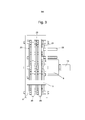
- Figure 8 is a section on the line B-B’ of figure 7.
- FIGS 1 to 4 give are overall views of the generator, for clarity enclosing covers and overall insulation and bracketing have been omitted.
- An input shaft 13 passes through an end plate 6 and is held axially and torsionally by bearings within housing 8. Shaft 13 is connected, in this case, to the output of a wind generator (not shown).
- the frame of the generator comprises two end plates 6 joined by spacers 15. The end plates 6 and spacers 15 make up the main structural frame of the device. Between the end plates are mounted two heat exchange assemblies 26 in this device.
- the heat exchanger assemblies comprise flat toroidal discs (41, 42, 43 seen detail in figure 8), disposed laterally to shaft 13 but not connected thereto, with shaft 13 passing through a hole at the centre of the heat exchangers. Although two heat exchangers assemblies are shown, the number can be varied to suit the input and output requirements of the generator design.
- Heat transfer fluid pipes 25 pass through the end plate 6 and provide the heat transfer fluid flow entry and return pipes to the heat exchange assemblies 26.
- the shaft 13 is mounted in bearings 12 within housing 8. Mounted on shaft 13 are magnetic housing disc mounting bosses 4 and 5. Mounting bosses 4 and 5 transfer rotation of the shaft to rotatable disc assemblies 21, 22 and 23. Three rotatable discs are present in this design, the two outer disc assemblies 21 and 23, having permanent magnets 3 mounted on one side only, and a double sided rotatable disc 22 having permanent magnets mounted on both sides of the disc. The outer assemblies are disposed to rotate close to the outer sides of the heat exchange assemblies 26, and the double sided rotatable disc assembly 22 to rotate between the heat exchanger assembles 26.
- the heat exchanger assemblies 26 are held in position relative to the end plates 6 by mounting bars 9 passing through wings 27 on the heat exchangers and into the end plates 6 (see detail in figure 1).
- Permanent magnets 3 are disposed radially around the rotatable disc assembles 21, 22, and 23.
- the permanent magnets 3 are formed on a steel disc 24, itself mounted on a steel disc 34, having holes 35 through which bolts 36 (figure 4) pass to attach the assembly to the mounting bosses 4 and 5.
- the magnets 3 themselves are mounted on the assemblies to produce alternating field direction N S N S as indicated in Figure 5. An alternating field is also maintained from magnet assembly to magnet assembly through the device.
- the heat exchanger assemblies 26 comprise an inner disc 41 and two outer discs 42 and 43 mounted brazed together, other conventional methods can be used to hold the two outer discs to the inner disc, including welding or screwing, but whatever methods is used it is essential that these discs should be sealed together.
- These discs (41, 42, 43) are produced from a highly conductive material, in this example copper was used but aluminium and its alloys is also suitable as are various other alloys of copper and other metals.
- the two outer discs 42 and 43 form the walls of the heat exchanger and the central disc 41 has etched through it a serpentine path 45 in which a heat transfer medium can pass, in this example pressurized water at typically 1 to 3 bar was used.
- the serpentine path 45 provides large amounts of turbulence as the heat transfer medium passes through it, it also has a large surface area within the discs maximising the opportunity for heat transfer from the discs 41, 42 and 43 to the heat transfer medium.
- the path 45 in disc 41 is connected to the heat transfer fluid pipes through inlet and or outlet bosses 44.
- the disc 41 is thus itself a heat exchanger, as are discs 42, and 43 in contact with the fluid in fluid path 45.
- the heat exchanger assemblies 26 are mounted rigidly within the device but in such a way that they do not touch or scrape the rotatable disc assemblies 21. 22 and 23, although they must be in very close proximity.
- the heat exchangers must be encased in a highly insulating material. This insulation is indicated by item number 51 around the periphery of the heat exchanger assembly, and materials 48 covering the faces of the heat exchanger assembly.
- the material used was a compressed fibre sheet 3mm thick. There are many alternatives, the main criterion in selection being that the material should be of sufficient thickness to insulate but also be sufficiently thin to allow close proximity of the heat exchanger assembly to the maximum flux density of the magnets 3. Heat loss through conduction must also be reduced in the mounting of the heat exchangers.
- the bars 9 mount the heat exchanger assembles in position. As the mounting of the heat exchangers can be a route for conductive heat loss, the bars 9 are isolated from the discs 41, 42 and 43 by mounting bushes 50 the bushes being produced from a suitably insulating but structural material. The bars 9 are threaded and are held in place in the wings 27 of the heat exchanger assembly 26 by nuts 47 bearing on washers 46. By turning the mounting nuts 47, the position of the heat exchangers can be adjusted to ensure optimum proximity of the rotatable disc assemblies 21, 22, and 23.
- pressurized water was used as the heat transfer fluid.
- Anti-freeze or coolants can be added to the water to increase its boiling temperature and to prevent freezing in inactive periods.
- Water vapour (steam) could also be used; liquid water would be pumped in to the path 45, and raised to steam before exiting.
- the heat generator could be part of a pressurized closed loop system with a pump fitted as part of the unit.
- water would be the most cost effective option as the heat transfer medium, other heat transfer fluids can be used.
- mineral oils that have a higher boiling point than water may be advantageous where substantial quantities of heat are being generated and need to be removed from the heat exchanger(s).
- the magnetic flux density can be varied. This can be very useful when the generator is connected to a wind turbine.
- One device to control the magnetic flux density works on the same principles as a centrifugal governor. Weights are attached to the shaft 13 on mechanical linkages. As rotational speed increases, the weights are flung outwards under centrifugal force. The transmitted force from this can then push the outermost rotatable disc assemblies 21 and 23 via further conventional mechanical linkages closer to the heat exchanger assemblies 26 increasing the flux density, such that they absorb more power.
- the up and down motion found in some a wave energy generators may make it easier to implement the invention, if the discs 41, 42 and 43 described in the figures were placed by plates, with the magnets (3) driven up and down with respect to the heat exchanger thus from the output of such a device.
Landscapes
- Physics & Mathematics (AREA)
- Electromagnetism (AREA)
- General Induction Heating (AREA)
- Water Treatment By Electricity Or Magnetism (AREA)
Abstract
Description
Claims (27)
- A heat generator comprising a magnetic field which intersects a heat exchanger characterised in that the heat exchanger (26) comprises a first flat plate that is both electrically conducting, said first plate having a fluid path (45) in the plane of the plate and wherein heat generated in said plate induction as a result of relative movement of the magnetic field with respect to the plate is transferred to any fluid in the fluid path.
- A heat generator according to claim 1 characterised in that the entry and exit (44) to the fluid path are disposed close together on the periphery of the first disc and the fluid path (45) passes substantially all the way around the plate within the plane of the plate.
- A heat generator according to claim 2 characterised in that the fluid path (45) is sinuous.
- A heat generator according to claim 3 characterised in that the fluid path (45) is serpentine.
- A heat generator according to any preceding claim characterised in that in the heat exchanger (26) additionally comprises two further flat plates which will generate heat under the influence of relative movement of the magnetic field with respect to the plates as a consequence of their being electrically conducting and the first plate being sandwiched between these two further plates.
- A heat generator according to claim 5 characterised in that the further plates provide walls for the fluid path (45).
- A heat generator according to any preceding claim characterised in that the first plate and any further plates comprise a first disc (42) and further discs (42, 43) respectively disposed around a shaft (13) which shaft can drive the magnetic field to rotate about the shaft and intersect the heat exchanger (26).
- A heat generator according to claim 7 characterised in that the heat exchanger is disposed between a pair of rotatable discs (21, 22, 23), said rotatable discs having magnets (3) mounted on their surfaces facing the heat exchanger (26), one each of the pair being mounted on the shaft (13) each side of the heat exchanger (26).
- A heat generator according to claim 8 characterised in that it comprises a plurality of the heat exchangers (26) and in which any rotatable discs (22) that is between two heat exchangers (26) has magnets (3) disposed on both sides of the said rotatable disc.
- A heat generator according to claim 8 or 9 characterised in that the magnets (3) are permanent magnets disposed radially with respect to the shaft (13).
- A heat generator according to claim 10 characterised in that the permanent magnets (3) are mounted on the rotatable discs (21, 22, 23) such that the poles of the magnets on one of the pairs of rotatable discs are all aligned in one direction and the same poles of the magnets of the other one of the pair of rotatable discs are aligned in the opposite direction.
- A heat generator according to any one of claims 8 to 11 characterised in that it includes adjustment means (47) whereby the relative position of the rotatable discs in respect to the heat exchangers (26) can be adjusted.
- A heat generator according to any one of claims 8 to 12 characterised in that the rotatable discs (21, 22, 23) are part of an assembly comprising a first ferromagnetic disc (24) on which permanent magnets (3) are mounted and a second ferromagnetic disc (34) to which is attached the first ferromagnetic disc (24), the second ferromagnetic disc (34) being attached to the shaft (13).
- A heat generator according to any preceding claim characterised in being mounted in a frame (6, 15) supporting the heat exchanger(s) (26) but thermally isolated therefrom.
- A heat generator according to claim 14 characterised in that the outside of the frame is thermally insulated.
- A heat generator according to any preceding claim characterised in that the electrically conducting plate(s) or disc(s) (41, 42, 43) is thermally insulated.
- A heat generator according to any preceding claim characterised in that the the magnetic field is moved relatively with respect to the heat exchanger(s) (26) by the output a renewable energy device such as a wind turbine or a wave energy device.
- A heat generator according to claim 17 characterised in additionally including a governing device to increase or decrease magnetic flux density.
- A heat generator according to claim 18 in which a shaft rotates the magnetic field characterised in that it includes weights attached to the shaft (13) said weights being flung outwards under centrifugal force as the rotational speed of the shaft increases and in consequence of which the outermost rotatable discs (21, 23) move closer to the heat exchanger (s) (26) increasing the flux density.
- A heat generator according to claim 18 or 19 characterised in that the outermost rotatable discs (21, 23) discs may be backed off from the heat exchanger(s) (26) when the generator is being started.
- A heat generator according to any preceding claim characterised in that the fluid passed through the fluid path (45) is pressurized water.
- A heat generator according to any preceding claim characterised in that the fluid passed through the fluid path is water containing anti-freeze.
- A heat generator according to any preceding claim characterised in that the fluid passed through the fluid path is water containing an additive to raise its boiling point.
- A heat generator according to any preceding claim characterised in that the fluid passed through the fluid path is water containing anti-freeze.
- A heat generator according to any preceding claim characterised in that the fluid passing through the fluid path is a liquid other than water.
- A heat exchanger according to any preceding claim characterised in that the liquid is a mineral oil.
- A heat generator according to any preceding claim characterised in that the fluid path is part of a closed loop heating system.
Priority Applications (2)
| Application Number | Priority Date | Filing Date | Title |
|---|---|---|---|
| GB1222757.5A GB2495027A (en) | 2010-06-16 | 2011-06-15 | Heat generator |
| US13/704,844 US9883552B2 (en) | 2010-06-16 | 2011-06-15 | Heat generator |
Applications Claiming Priority (2)
| Application Number | Priority Date | Filing Date | Title |
|---|---|---|---|
| GBGB1010048.5A GB201010048D0 (en) | 2010-06-16 | 2010-06-16 | Heat generator |
| GB1010048.5 | 2010-06-16 |
Publications (1)
| Publication Number | Publication Date |
|---|---|
| WO2011158030A1 true WO2011158030A1 (en) | 2011-12-22 |
Family
ID=42471719
Family Applications (1)
| Application Number | Title | Priority Date | Filing Date |
|---|---|---|---|
| PCT/GB2011/051120 Ceased WO2011158030A1 (en) | 2010-06-16 | 2011-06-15 | Heat generator |
Country Status (3)
| Country | Link |
|---|---|
| US (1) | US9883552B2 (en) |
| GB (2) | GB201010048D0 (en) |
| WO (1) | WO2011158030A1 (en) |
Cited By (1)
| Publication number | Priority date | Publication date | Assignee | Title |
|---|---|---|---|---|
| US10425998B2 (en) | 2013-08-22 | 2019-09-24 | Rotaheat Limited | Heat generator |
Families Citing this family (9)
| Publication number | Priority date | Publication date | Assignee | Title |
|---|---|---|---|---|
| US9205349B2 (en) * | 2011-08-19 | 2015-12-08 | Waterpointe-Global Llc | Method and apparatus for heating during a liquid purification process using an electromagnetic heater |
| US20140110947A1 (en) * | 2012-10-24 | 2014-04-24 | Vestas Wind Systems A/S | Wind turbine generator having an eddy current brake, wind turbine having such a generator, and associated methods |
| ES2569578B1 (en) * | 2014-10-07 | 2017-01-25 | Maxwell & Lorentz, S.L. | HEAT GENERATION SYSTEM BY MAGNETIC INDUCTION |
| WO2017004729A1 (en) * | 2015-07-03 | 2017-01-12 | Energía Vectorial Limitada. | Device for heating fluids by means of rotary magnetic induction |
| EP3414973B1 (en) * | 2016-02-10 | 2020-04-22 | Rotaheat Limited | Heat generator |
| US11564290B2 (en) * | 2018-07-25 | 2023-01-24 | Heat X, LLC | Magnetic induction style furnace or heat pump incorporating forced air or fluid blowers |
| US11564289B2 (en) * | 2018-07-25 | 2023-01-24 | Heat X, LLC | Magnetic induction style furnace or heat pump with variable blower functionality including retractable magnet arrays |
| US11564288B2 (en) | 2018-07-25 | 2023-01-24 | Heat X, LLC | Magnetic induction style furnace or heat pump or magnetic refrigerator having combination conductive and heated or cooled fluid redirecting rotational plate |
| WO2021072148A1 (en) * | 2019-10-09 | 2021-04-15 | Heat X, LLC | Magnetic induction furnace, cooler or magnetocaloric fluid heat pump with varied conductive plate configurations |
Citations (5)
| Publication number | Priority date | Publication date | Assignee | Title |
|---|---|---|---|---|
| US4511777A (en) * | 1984-07-19 | 1985-04-16 | Frank Gerard | Permanent magnet thermal energy system |
| JP2000123962A (en) * | 1998-10-19 | 2000-04-28 | Usui Internatl Ind Co Ltd | Magnet type heater |
| US6297484B1 (en) | 1998-04-09 | 2001-10-02 | Usui Kokusai Sanyo Kaisha Ltd | Magnetic heater |
| WO2002087285A1 (en) * | 2001-04-19 | 2002-10-31 | Paolo Arnaldo Rosastro | Device for converting magnetic energy into thermal energy, particularly for heating material in a solid or fluid state |
| US20030066830A1 (en) * | 2001-07-24 | 2003-04-10 | Magtec Llc | Magnetic heater apparatus and method |
Family Cites Families (6)
| Publication number | Priority date | Publication date | Assignee | Title |
|---|---|---|---|---|
| US4217475A (en) * | 1978-08-25 | 1980-08-12 | Hagerty Research & Development Co., Inc. | Apparatus for transferring heat to fluids |
| FR2514966B1 (en) | 1981-10-16 | 1987-04-24 | Materiel Magnetique | CINETIC HEAT ROTATION ENERGY CONVERTER BY EDGE CURRENT GENERATION |
| EP0579073A1 (en) | 1992-07-13 | 1994-01-19 | Thomas Margittai | Electromagnetic processor for heating and mixing liquids |
| US5914065A (en) * | 1996-03-18 | 1999-06-22 | Alavi; Kamal | Apparatus and method for heating a fluid by induction heating |
| SE517772C2 (en) * | 1999-06-18 | 2002-07-16 | Bakelit Konstr Ab | Heat generator for reducing emissions from motor vehicles |
| US7573009B2 (en) * | 2001-07-24 | 2009-08-11 | Magtec Energy, Llc | Controlled magnetic heat generation |
-
2010
- 2010-06-16 GB GBGB1010048.5A patent/GB201010048D0/en not_active Ceased
-
2011
- 2011-06-15 GB GB1222757.5A patent/GB2495027A/en not_active Withdrawn
- 2011-06-15 WO PCT/GB2011/051120 patent/WO2011158030A1/en not_active Ceased
- 2011-06-15 US US13/704,844 patent/US9883552B2/en active Active
Patent Citations (5)
| Publication number | Priority date | Publication date | Assignee | Title |
|---|---|---|---|---|
| US4511777A (en) * | 1984-07-19 | 1985-04-16 | Frank Gerard | Permanent magnet thermal energy system |
| US6297484B1 (en) | 1998-04-09 | 2001-10-02 | Usui Kokusai Sanyo Kaisha Ltd | Magnetic heater |
| JP2000123962A (en) * | 1998-10-19 | 2000-04-28 | Usui Internatl Ind Co Ltd | Magnet type heater |
| WO2002087285A1 (en) * | 2001-04-19 | 2002-10-31 | Paolo Arnaldo Rosastro | Device for converting magnetic energy into thermal energy, particularly for heating material in a solid or fluid state |
| US20030066830A1 (en) * | 2001-07-24 | 2003-04-10 | Magtec Llc | Magnetic heater apparatus and method |
Cited By (1)
| Publication number | Priority date | Publication date | Assignee | Title |
|---|---|---|---|---|
| US10425998B2 (en) | 2013-08-22 | 2019-09-24 | Rotaheat Limited | Heat generator |
Also Published As
| Publication number | Publication date |
|---|---|
| US9883552B2 (en) | 2018-01-30 |
| GB201010048D0 (en) | 2010-07-21 |
| GB2495027A (en) | 2013-03-27 |
| US20130092681A1 (en) | 2013-04-18 |
| GB201222757D0 (en) | 2013-01-30 |
Similar Documents
| Publication | Publication Date | Title |
|---|---|---|
| US9883552B2 (en) | Heat generator | |
| US9473049B2 (en) | Induction heating apparatus and power generation system comprising the same | |
| TWI587746B (en) | Power system | |
| CA2519448C (en) | Electric machine with magnetic flux regulating means | |
| JP5413814B2 (en) | Power generation system | |
| CN101647129B (en) | Generator apparatus and method | |
| EP3217521B1 (en) | Eddy current type heating device | |
| CN101647128A (en) | Thermomagnetic generator device and energy conversion method | |
| US20130008887A1 (en) | Water Heating System | |
| US10701768B2 (en) | Eddy current heat generating apparatus | |
| JP7304010B2 (en) | Energy storage system and variable power stable utilization system | |
| AU2016336721A1 (en) | Induction heating device and power generation system | |
| JP5344380B2 (en) | Power generation system | |
| JP5545436B2 (en) | Power generation system | |
| EP2878070A2 (en) | Active segment of a wind turbine rotary electric machine, rotary electric machine, and wind turbine | |
| CN201210758Y (en) | Eddy current heater | |
| JP5293626B2 (en) | Induction heating apparatus and power generation system including the same | |
| JP2011129433A (en) | Induction heating device and power generation system equipped with the same | |
| JP2017010696A (en) | Induction heating apparatus and power generation system | |
| WO2011093192A1 (en) | Power generation system | |
| JP5435357B2 (en) | Power generation system | |
| JP7065224B1 (en) | Energy conversion element | |
| JP5778969B2 (en) | Power generation system | |
| JP2017010698A (en) | Induction heating apparatus and power generation system | |
| WO2013038414A1 (en) | Apparatus, system and method for heating fluid |
Legal Events
| Date | Code | Title | Description |
|---|---|---|---|
| 121 | Ep: the epo has been informed by wipo that ep was designated in this application |
Ref document number: 11735904 Country of ref document: EP Kind code of ref document: A1 |
|
| ENP | Entry into the national phase |
Ref document number: 1222757 Country of ref document: GB Kind code of ref document: A Free format text: PCT FILING DATE = 20110615 |
|
| NENP | Non-entry into the national phase |
Ref country code: DE |
|
| WWE | Wipo information: entry into national phase |
Ref document number: 13704844 Country of ref document: US Ref document number: 1222757.5 Country of ref document: GB |
|
| 122 | Ep: pct application non-entry in european phase |
Ref document number: 11735904 Country of ref document: EP Kind code of ref document: A1 |
|
| ENPC | Correction to former announcement of entry into national phase, pct application did not enter into the national phase |
Ref country code: GB |