WO2011136618A2 - 멀티 캐리어 시스템에서 e-mbs 단말을 위한 페이징 방법 및 장치 - Google Patents
멀티 캐리어 시스템에서 e-mbs 단말을 위한 페이징 방법 및 장치 Download PDFInfo
- Publication number
- WO2011136618A2 WO2011136618A2 PCT/KR2011/003227 KR2011003227W WO2011136618A2 WO 2011136618 A2 WO2011136618 A2 WO 2011136618A2 KR 2011003227 W KR2011003227 W KR 2011003227W WO 2011136618 A2 WO2011136618 A2 WO 2011136618A2
- Authority
- WO
- WIPO (PCT)
- Prior art keywords
- carrier
- paging
- network
- message
- mbs
- Prior art date
Links
Images


Classifications
-
- H—ELECTRICITY
- H04—ELECTRIC COMMUNICATION TECHNIQUE
- H04W—WIRELESS COMMUNICATION NETWORKS
- H04W68/00—User notification, e.g. alerting and paging, for incoming communication, change of service or the like
- H04W68/02—Arrangements for increasing efficiency of notification or paging channel
- H04W68/025—Indirect paging
-
- H—ELECTRICITY
- H04—ELECTRIC COMMUNICATION TECHNIQUE
- H04W—WIRELESS COMMUNICATION NETWORKS
- H04W4/00—Services specially adapted for wireless communication networks; Facilities therefor
- H04W4/06—Selective distribution of broadcast services, e.g. multimedia broadcast multicast service [MBMS]; Services to user groups; One-way selective calling services
-
- H—ELECTRICITY
- H04—ELECTRIC COMMUNICATION TECHNIQUE
- H04W—WIRELESS COMMUNICATION NETWORKS
- H04W60/00—Affiliation to network, e.g. registration; Terminating affiliation with the network, e.g. de-registration
- H04W60/06—De-registration or detaching
-
- H—ELECTRICITY
- H04—ELECTRIC COMMUNICATION TECHNIQUE
- H04W—WIRELESS COMMUNICATION NETWORKS
- H04W64/00—Locating users or terminals or network equipment for network management purposes, e.g. mobility management
-
- H—ELECTRICITY
- H04—ELECTRIC COMMUNICATION TECHNIQUE
- H04W—WIRELESS COMMUNICATION NETWORKS
- H04W76/00—Connection management
- H04W76/10—Connection setup
- H04W76/19—Connection re-establishment
-
- H—ELECTRICITY
- H04—ELECTRIC COMMUNICATION TECHNIQUE
- H04W—WIRELESS COMMUNICATION NETWORKS
- H04W72/00—Local resource management
- H04W72/30—Resource management for broadcast services
Definitions
- the present disclosure relates to a multi-carrier system, and more particularly, to a paging method and apparatus for an E-MBS terminal.
- E-MBS 16m Enhanced Multicast and Broadcast Service
- E-MBS Advanced Multicast and Broadcast Services
- MSTID multicast STID
- FID FID
- E-MBS service is provided only in downlink, and can be coordination or synchronized between base stations belonging to one group to allow macro diversity.
- Each E-MBS connection is associated with the service flow provided with QoS and traffic parameters for the service flow.
- Service flows for transmitting the E-MBS data may be described as an example to individual terminals participating in the service while the terminal performs a general operation. During such description, the terminal identifies the service and learns the parameters related to the service flow.
- Each base station capable of providing an E-MBS service belongs to a specific E-MBS zone, and one base station may belong to a plurality of E-MBS zones.
- An E-MBS zone is defined as one set of base stations where the same MSTID and FID are used to transmit the content of a particular service flow.
- Each E-MBS zone is identified by a unique E-MBS zone ID.
- the MSTIDs and FIDs used for common E-MBS content and services must be the same for all base stations in the same E-MBS zone.
- the user may include information to be transmitted by modulating the amplitude, frequency and / or phase of the sine wave or the periodic pulse wave.
- a sine wave or pulse wave that serves to carry information is called a carrier.
- the carrier modulation method includes a single carrier modulation scheme (SCM) or a multi-carrier modulation scheme (MCM).
- SCM single carrier modulation scheme
- MCM multi-carrier modulation scheme
- the single carrier modulation method is a modulation method in which all information is loaded on one carrier and modulated.
- Multi-carrier modulation divides the entire bandwidth channel of one carrier into sub-channels having several small bandwidths, and multiple narrow-band sub-carriers through each sub-channel. Refers to a technique for transmitting in multiples.
- each subchannel can be approximated to a flat channel (Flat Channel) due to the small bandwidth.
- the user can compensate for the distortion of the channel using a simple equalizer.
- the multi-carrier modulation scheme may be implemented at high speed using fast Fourier transform (FFT). That is, it is advantageous for high speed data transmission compared to the single carrier modulation method (SCM).
- FFT fast Fourier transform
- embodiments of the present invention disclose a multi-carrier system that supports broadband by using one or more carriers in a carrier aggregation.
- the multi-carrier system described below represents a case in which one or more carriers are bundled and used, unlike the multi-carrier modulation scheme in which one carrier is divided and used.
- a multi-band or multi-carrier
- a plurality of carriers for example, multiple frequency carriers (FCs)
- FCs frequency carriers
- MAC medium access control
- FIG. 1 (a) and (b) are diagrams for explaining a multi-band radio frequency (RF) based signal transmission and reception method.
- RF radio frequency
- one medium access control layer at a transmitting end and a receiving end may manage multiple carriers in order to use multicarriers efficiently.
- both the transmitting end and the receiving end can transmit and receive multicarriers.
- frequency carriers (FCs) managed in one medium access control layer do not need to be adjacent to each other, which is flexible in terms of resource management. That is, both contiguous aggregation and non-contiguous aggregation are possible.
- physical layer (PHY) 0, physical layer 1, .. physical layer n-2, physical layer n-1 represent multiple bands according to the present technology, and each band is It may have a frequency carrier (FC) size allocated for a specific service according to a predetermined frequency policy.
- FC frequency carrier
- the physical layer 0 (RF carrier 0) may have a frequency band size allocated for general FM radio broadcasting
- the physical layer 1 (RF carrier 1) may have a frequency band size allocated for cellular communication.
- each frequency band may have a different frequency band size according to each frequency band characteristic.
- each frequency carrier FC has an A [MHz] size.
- each frequency allocation band may be represented by a carrier frequency for using a baseband signal in each frequency band.
- each frequency allocation band is referred to as a "carrier frequency band” or each carrier frequency band when there is no confusion. Representative simply referred to as "carrier”.
- 3GPP LTE-A 3GPP LTE-A
- a component carrier to distinguish the above-mentioned carrier from the subcarrier (subcarrier) used in the multi-carrier scheme.
- multi-band scheme described above may be referred to as a “multi-carrier” scheme or a “carrier aggregation” scheme.
- 2 (a) and 2 (b) show an example in which a multi-carrier is used in a general wireless communication system.
- a multicarrier in a general technique may be a contiguous carrier aggregation of contiguous carriers, and a non-contiguous carrier aggregation of discontinuous carriers as shown in (b) of FIG. 2.
- the unit for combining these carriers is a basic bandwidth unit of a legacy technology (e.g. LTE, Long Term Evolution (LTE) -advanced system, LTE, IEEE 802.16e in the IEEE 802.16m system).
- LTE Long Term Evolution
- LTE Long Term Evolution
- IEEE 802.16e in the IEEE 802.16m system
- the first carrier refers to a carrier on which the traffic of the terminal and the base station, the exchange of complete physical layer and full PHY / MAC control information is performed.
- the primary carrier can also be used for the general operation of the terminal, such as network entry.
- Each terminal has one main carrier in one cell.
- the second carrier (or secondary carrier) is an additional carrier that can be used for the exchange of traffic according to the base station specific allocation commands and laws usually received from the first carrier.
- the second carrier may include control signaling to support multicarrier operation.
- a carrier of a multi-carrier system based on the primary and secondary carriers described above may be divided into a Fully configured carrier and a Partially configured carrier as follows.
- Fully configured carrier refers to a carrier on which control signaling is configured.
- information and parameters for multi-carrier operation and other carriers may be included in the control channels.
- Partially configured carrier includes all control channels for supporting downlink transmission in downlink carriers without pairing uplink carriers in TDD DL transmission or frequency division duplex (FDD) mode. This refers to the carrier to be set.
- FDD frequency division duplex
- the terminal performs initial network entry through the primary carrier, and information on the multi-carrier capabilities of each other in the registration process through the exchange of registration request / response (AAI_REG-REQ / RSP) messages with the base station. Can be exchanged.
- AAA_REG-REQ / RSP registration request / response
- the present specification is to solve the problem that the paging carrier to which the paging message is transmitted according to whether the idle mode terminal receives the E-MBS service, by reporting the start or end of receiving the E-MBS service to the network It is an object of the present invention to provide a method for properly setting a paging carrier according to whether an E-MBS service is received.
- the present specification provides a method for transmitting the E-MBS service reception status information of the terminal to the base station when the terminal transitions to the idle mode.
- the present specification is to provide a method for informing the base station to the carrier that can be network re-entry, if network re-entry as a paging carrier is not possible.
- the present disclosure provides a method for receiving a paging message of an idle mode terminal in a multi-carrier system, the method comprising: receiving a paging message from a network through a first carrier corresponding to a predetermined condition in a paging listening period; Transmitting a first ranging request message to the network, the first ranging request message including control information indicating a location update procedure for initiating reception of an E-MBS service; Determining a second carrier to which the E-MBS service is transmitted as a paging carrier; And receiving a paging message from the network on the determined second carrier.
- the determining of the second carrier as a paging carrier may further include receiving paging carrier determination information indicating that the paging message is transmitted from the network through a second carrier through which an E-MBS service is transmitted. It is done.
- the paging carrier determination information may be received from the network through a ranging response (RNG-RSP) message.
- RNG-RSP ranging response
- the method may further include: transmitting a second ranging request message to the network, the second ranging request message including control information indicating a location update procedure for notifying completion of E-MBS service reception; Determining the first carrier as a paging carrier; And receiving the paging message from the network through the determined first carrier.
- determining the first carrier as a paging carrier further includes receiving a second ranging response message from the network, the second ranging response message including paging carrier determination information indicating that the paging message is transmitted on the first carrier. It is characterized by.
- the predetermined condition is a modulo operation of a de-registration identifier (DID) used to distinguish an idle mode terminal from the number of carriers (N) in a paging group to which the network belongs (DID modulo N). It is characterized by that.
- DID de-registration identifier
- the network is characterized in that the base station or a paging controller (paging controller).
- the first carrier may be a fully configured carrier
- the second carrier may be a fully configured carrier or a partially configured carrier.
- the first ranging request message is transmitted through the first carrier, and the second ranging request message is transmitted through the second carrier. It is characterized by.
- the first and second ranging request messages are transmitted through the first carrier.
- the method may further include transmitting a deregistration request message including E-MBS service reception status information to the base station; And receiving a deregistration response message from the base station in response to the deregistration request message.
- the E-MBS service reception status information is characterized in that the information indicating the start or end of E-MBS service reception.
- the deregistration request message may further include paging carrier selection mode information indicating a request for transmitting a paging message through one of the first carrier and the second carrier. .
- the deregistration response message may further include paging carrier selection mode information indicating that a paging message is transmitted through one of the first carrier and the second carrier.
- the present specification provides a terminal for receiving a paging message (paging message) in a multi-carrier system, a wireless communication unit for transmitting and receiving a wireless signal with the outside; And a control unit connected to the wireless communication unit, wherein the control unit controls the wireless communication unit to receive a paging message from a network through a first carrier corresponding to a predetermined condition, and provides a location for notifying the start of receiving an E-MBS service. Control the wireless communication unit to transmit a first ranging request message including control information indicating an update procedure to the network, determine a second carrier to which an E-MBS service is transmitted as a paging carrier, and determine the determined second carrier Control to receive a paging message from the network through.
- the controller may control the wireless communication unit to transmit a second ranging request message to the network, the second ranging request message including control information indicating a location update procedure for notifying the end of E-MBS service reception, and the first carrier to be a paging carrier. And control the wireless communication unit to receive the paging message from the network through the determined first carrier.
- the predetermined condition is a modulo operation of a de-registration identifier (DID) used to distinguish an idle mode terminal from the number of carriers (N) in a paging group to which the network belongs (DID modulo N). It is characterized by that.
- DID de-registration identifier
- the present disclosure provides a network re-entry method of an idle mode terminal in a multi-carrier system, the method comprising: receiving a paging message from a base station including carrier information indicating a network re-entrant carrier through a paging carrier; And performing network reentry to the base station based on the carrier information, wherein the paging carrier is a partially configured carrier.
- the carrier information is characterized in that the physical carrier index (physical carrier index).
- the method may further include determining any one of the carrier information when there are a plurality of network reentrant carriers.
- the determining of any one carrier may be performed randomly or modulo operation of an idle mode terminal identifier (DID) and the number of network reentrant carriers.
- DID idle mode terminal identifier
- the paging carrier may be a carrier through which the E-MBS is transmitted or a carrier corresponding to a modulo operation result value of the idle mode terminal identifier and the number of carriers in the paging group.
- an idle mode terminal notifies the network (base station or paging controller) of starting or ending reception of an E-MBS service in a multi-carrier supporting system, thereby effectively setting a paging carrier of the terminal.
- the present specification has an effect that the base station informs the carrier (network reentry) to the terminal (network reentry), thereby reducing the process of cell reselection unnecessarily.
- FIG. 1 (a) and (b) are diagrams for explaining a multi-band radio frequency (RF) based signal transmission and reception method.
- RF radio frequency
- 2 (a) and 2 (b) show an example in which a multi-carrier is used in a general wireless communication system.
- FIG. 3 is a block diagram illustrating a wireless communication system.
- FIG. 4 shows an internal block diagram of a terminal and a base station in a wireless access system.
- FIG. 5 is a flowchart illustrating a method of receiving a paging message of a terminal according to an E-MBS service reception status (start or end) report according to the first embodiment of the present disclosure.
- FIG. 6 is a flowchart illustrating a method of updating a paging carrier by performing a location update process for reporting an E-MBS service reception status according to the first embodiment of the present specification.
- 7 (a) and 7 (b) illustrate another method of updating a paging carrier by performing a location update process for reporting an E-MBS service reception status as another example of the first embodiment of the present specification. It is a flow chart.
- FIG. 8 is an example illustrating a method of transmitting E-MBS service reception status information to a base station by a terminal according to a second embodiment of the present disclosure to deregister with a base station.
- 9 to 12 show an overall flowchart for configuring a paging carrier of the E-MBS terminal according to the embodiments of the present disclosure, respectively.
- CDMA code division multiple access
- FDMA frequency division multiple access
- TDMA time division multiple access
- OFDMA orthogonal frequency division multiple access
- SC-FDMA single carrier frequency division multiple access
- CDMA may be implemented with a radio technology such as Universal Terrestrial Radio Access (UTRA) or CDMA2000.
- TDMA may be implemented with wireless technologies such as Global System for Mobile communications (GSM) / General Packet Radio Service (GPRS) / Enhanced Data Rates for GSM Evolution (EDGE).
- GSM Global System for Mobile communications
- GPRS General Packet Radio Service
- EDGE Enhanced Data Rates for GSM Evolution
- OFDMA may be implemented in a wireless technology such as IEEE 802.11 (Wi-Fi), IEEE 802.16 (WiMAX), IEEE 802-20, Evolved UTRA (E-UTRA), or the like.
- IEEE 802.16m is an evolution of IEEE 802.16e and provides backward compatibility with systems based on IEEE 802.16e.
- UTRA is part of the Universal Mobile Telecommunications System (UMTS).
- 3rd Generation Partnership Project (3GPP) Long Term Evolution (LTE) is part of Evolved UMTS (E-UMTS) using Evolved-UMTS Terrestrial Radio Access (E-UTRA), which employs OFDMA in downlink and SC in uplink -FDMA is adopted.
- LTE-A Advanced is an evolution of 3GPP LTE.
- FIG. 3 is a block diagram illustrating a wireless communication system.
- Wireless communication systems are widely deployed to provide various communication services such as voice and packet data.
- a wireless communication system includes a mobile station (MS) 10 and a base station 20 (BS).
- the terminal 10 may be fixed or mobile, and may be called by other terms such as a user equipment (UE), a user terminal (UT), a subscriber station (SS), a wireless device, an advanced mobile station (AMS), and the like. have.
- UE user equipment
- UT user terminal
- SS subscriber station
- AMS advanced mobile station
- the base station 20 generally refers to a fixed station for communicating with the terminal 10 and may be referred to in other terms such as a NodeB, a base transceiver system (BTS), and an access point. .
- BTS base transceiver system
- One or more cells may exist in one base station 20.
- the wireless communication system may be an Orthogonal Frequency Division Multiplexing (OFDM) / Orthogonal Frequency Division Multiple Access (OFDMA) based system.
- OFDM Orthogonal Frequency Division Multiplexing
- OFDMA Orthogonal Frequency Division Multiple Access
- OFDM uses multiple orthogonal subcarriers. OFDM uses orthogonality between inverse fast fourier transforms (IFFTs) and fast fourier transforms (FFTs).
- IFFTs inverse fast fourier transforms
- FFTs fast fourier transforms
- the transmitter data is sent by performing an IFFT.
- the receiver performs FFT on the received signal to recover the original data.
- the transmitter uses an IFFT to combine multiple subcarriers, and the receiver uses a corresponding FFT to separate multiple subcarriers.
- a slot is also the minimum possible data allocation unit, defined by time and subchannels.
- a subchannel may be composed of a plurality of tiles.
- the subchannel consists of 6 tiles, and one burst in uplink may consist of 3 OFDM symbols and 1 subchannel.
- each tile may include 4 contiguous subcarriers on 3 OFDM symbols.
- each tile may comprise three contiguous subcarriers on three OFDM symbols.
- the bin includes 9 contiguous subcarriers on the OFDM symbol.
- a band refers to a group of four rows of bins, and an adaptive modulation and coding (AMC) subchannel consists of six contiguous bins in the same band.
- AMC adaptive modulation and coding
- FIG. 4 shows an internal block diagram of a terminal and a base station in a wireless access system.
- the terminal 10 includes a control unit 11, a memory 12, and a radio communication (RF) unit 13.
- RF radio communication
- the terminal also includes a display unit, a user interface unit, and the like.
- the controller 11 implements the proposed function, process and / or method. Layers of the air interface protocol may be implemented by the controller 11.
- the memory 12 is connected to the control unit 11 and stores a protocol or parameter for performing wireless communication. That is, it stores the terminal driving system, the application, and the general file.
- the RF unit 13 is connected to the control unit 11 and transmits and / or receives a radio signal.
- the display unit displays various information of the terminal, and may use well-known elements such as liquid crystal display (LCD) and organic light emitting diodes (OLED).
- the user interface may be a combination of a well-known user interface such as a keypad or a touch screen.
- the base station 20 includes a control unit 21, a memory 22, and a radio frequency unit (RF) unit 23.
- RF radio frequency unit
- the control unit 21 implements the proposed function, process and / or method. Layers of the air interface protocol may be implemented by the controller 21.
- the memory 22 is connected to the control unit 21 to store a protocol or parameter for performing wireless communication.
- the RF unit 23 is connected to the control unit 21 to transmit and / or receive a radio signal.
- the controllers 11 and 21 may include an application-specific integrated circuit (ASIC), another chipset, a logic circuit, and / or a data processing device.
- the memories 12 and 22 may include read-only memory (ROM), random access memory (RAM), flash memory, memory cards, storage media and / or other storage devices.
- the RF unit 13 and 23 may include a baseband circuit for processing a radio signal.
- the above-described technique may be implemented as a module (process, function, etc.) for performing the above-described function.
- the module may be stored in the memories 12 and 22 and executed by the controllers 11 and 21.
- the memories 12 and 22 may be inside or outside the controllers 11 and 21, and may be connected to the controllers 11 and 21 by various well-known means.
- Non-macro diversity transmission mode There are two modes for transmitting E-MBS traffic: non-macro diversity transmission mode and macro diversity transmission mode.
- Non-macro diversity mode is used when base stations in the same zone coordination of transmissions in the same frame and cannot use macro diversity mode. All base stations belonging to the same E-MBS zone transmit SDUs carrying the same contents in the same frame. These SDUs are mapped to MPDUs in the same frame. This means the same SDU fragments, the same fragment sequence number, and the same fragment size. This allows the same AMS to receive E-MBS transmissions from ABSs in the same zone.
- Macro diversity mode means that all ABS in a zone synchronizes E-MBS transmission, which means that all ABS in a zone transmit the same data using the same resources at the same time. This has the effect of obtaining macro diversity gain in E-MBS transmission.
- all ABS in the same zone share the following information:
- AAI_E-MBS-CFG message Information about the E-MBS configuration is periodically transmitted to terminals interested in the E-MBS using a MAC control message called an AAI_E-MBS-CFG message.
- the E-MBS configuration indicator specifies resources reserved for E-MBS traffic and additional information necessary for E-MBS operation in a downlink physical resource.
- E-MBS_ZONE_ID is used to indicate a service area in which the E-MBS ID and the FID for the E-MBS service flow are valid.
- the E-MBS zone ID to which the base station belongs is included in the E-MBS CFG message.
- the E-MBS zone ID cannot be '0'.
- the base station When the base station sends an AAI_DSA message to establish a connection to the E-MBS zone ID, the E-MBS zone ID will be encoded in the DSA message.
- One base station may have multiple E-MBS zone IDs for other E-MBS services.
- MSI refers to the number of consecutive super-frames in which the access network can schedule traffic for streams related to the MBS zone prior to the start of the MSI interval.
- the MSI can have intervals of several superframes and the length of the MSI interval, denoted by N MSI , depending on the special use of E-MBS.
- the E-MBS map message has a mapping address of E-MBS data associated with the E-MBS zone during one full MSI.
- the E-MBS map message is configured to be used to fully define one transmission situation for a given stream in one MSI.
- the indication of the MSI length is sent via an SCD message.
- the UE calculates the start of MSI as follows.
- the MSI starts with a superframe in which the N Superframe of the MSI satisfies the following conditions.
- the terminal can only demodulate E-MBS data bursts associated with the content selected by the user.
- the UE wakes up in each MSI section to check whether there is an E-MBS data burst to be demodulated.
- a paging group information message (PGID_Info message) is transmitted on all fully configured carriers.
- the paging advertisement message (AAI_PAG-ADV message) for the terminal is transmitted on only one of the fully configured carriers.
- the idle mode terminal determines a carrier index for monitoring a paging message in a paging listening interval of the terminal.
- the paging message transmitted in the paging listening interval is transmitted using the following rule.
- N is the number of carriers in the paging group at the base station used to transmit the paging message for the idle mode terminal.
- DID De-registration Identifier
- N is the number of carriers in the paging group at the base station used to transmit the paging message for the idle mode terminal.
- DID De-registration Identifier
- the paging carrier index corresponds to an ascending order of physical carrier indexes of carriers used for transmitting a paging message at the base station.
- the paging carrier indication bit is used to specify whether the carrier is a paging carrier or not. If the paging carrier indication is '1', the carrier indicates a paging carrier. Paging carrier indications of other carriers may be included in a paging group information message and may be included in a neighbor advertisement message (AAI_NBR-ADV) or a multi-carrier advertisement message (AAI_MC-ADV).
- the terminal determines if the paging carrier indication is included in the neighbor advertisement message.
- the paging carrier indication received via the message may be used.
- the paging advertisement message is sent on one or more frames starting from the second subframe within the super frame.
- the paging advertisement message for the E-MBS terminal may be transmitted on the same carrier as the dedicated carrier for the E-MBS.
- a paging carrier for receiving a paging message from a network is set to N in the DID. Determined by the modulo value, it will wait to receive a paging message from the network on the carrier corresponding to the paging carrier index. That is, when the idle mode terminal wants to receive the E-MBS service, if the terminal already has the E-MBS configuration information, the terminal receives the E-MBS service using the previously received E-MBS configuration information.
- the base station will perform paging to the terminal to the paging carrier before receiving the E-MBS service, the terminal It will be determined that the paging message is sent on the E-MBS carrier.
- the network may have a method of transmitting paging information of all terminals subscribed to the E-MBS service to the E-MBS carrier.
- the network may have a method of transmitting paging information of all terminals subscribed to the E-MBS service to the E-MBS carrier.
- it is necessary to transmit paging information of all the terminals subscribed to the E-MBS in one paging group to one E-MBS carrier. This may increase the paging overhead of the E-MBS carrier.
- the terminal reports the E-MBS service reception status (start or end) to the network so that the paging carrier of the terminal is appropriately set. How to do this will be described in detail through embodiments.
- the first embodiment provides a method of transmitting a paging message of a base station through the E-MBS service reception status (start or end) report of the idle mode terminal.
- a paging message is a carrier ('E-MBS carrier' or 'second' to which the E-MBS service is transmitted).
- the present invention provides a method of configuring a paging carrier of a terminal to be transmitted through a carrier ('first carrier') corresponding to a DID modulo N, rather than a carrier.
- FIG. 5 is a flowchart illustrating a method of receiving a paging message of a terminal according to an E-MBS service reception status (start or end) report according to the first embodiment of the present disclosure.
- the terminal when the idle mode terminal starts to receive the E-MBS service from the base station (S510), the terminal transmits a signal indicating the start of receiving the E-MBS service to the network (S520).
- the network may be a base station or a paging controller.
- the signal indicating the start of receiving the E-MBS service may be transmitted through a location update process of the terminal.
- a method of notifying the start of receiving the E-MBS service through the location update procedure will be described in detail below.
- the network When the network receives a signal indicating the start of receiving the E-MBS service from the terminal, the network updates the paging carrier index of the idle mode terminal to a carrier provided with the E-MBS service (S530).
- the network may transmit the updated paging carrier index, that is, the E-MBS carrier index, to the idle mode terminal (S540).
- the idle mode terminal receives a paging message from the network through the E-MBS carrier (S550).
- the idle mode terminal receiving the E-MBS service terminates the reception of the E-MBS service (S560)
- the idle mode terminal transmits a signal indicating the end of the E-MBS service reception to the network (S570).
- the network when the network receives a signal indicating the end of the E-MBS service reception from the idle mode terminal, the network and the paging carrier index (paging carrier index) of the terminal and the deregistration identifier (DID) of the idle mode terminal; Through the modulo operation of the value of N (carriers per paging group to which the base station belongs) (DID modulo N) it is set to the carrier index of the output value (S580).
- FIG. 6 is a flowchart illustrating a method of updating a paging carrier by performing a location update process for reporting an E-MBS service reception status according to the first embodiment of the present specification.
- a ranging request message including control information indicating a location update procedure for notifying start of receiving an E-MBS service is transmitted to a base station. Transmit (S630).
- control information is ranging purpose indication (Ranging purpose indication) indicating the ranging purpose.
- the ranging purpose indication information may be set to '0x1110'.
- the network when the network receives the ranging request message in which the ranging purpose indication information is set to '0x1110' from the idle mode terminal, the network sets the paging carrier of the terminal as a carrier to which the E-MBS service is transmitted (S640).
- the carrier on which the E-MBS service is transmitted may be a dedicated carrier for transmitting the E-MBS service.
- the network when the network (base station or paging controller) responds to a location update of the terminal, the network includes a paging carrier index set in the ranging response message to inform the terminal of the paging carrier.
- the terminal If the paging carrier index is not included in the ranging response message (AAI_RNG-RSP) transmitted to the idle mode terminal, the terminal automatically sets the E-MBS carrier as the paging carrier.
- the ranging request message including the control information indicating that the location update procedure for notifying the end of the E-MBS service reception to the network (base station or paging controller) It transmits (S670).
- control information is ranging purpose indication information
- the ranging purpose indication information may be set to '0x1111' as an example.
- the base station determines the paging carrier of the idle mode terminal of the idle mode terminal.
- the DID is set to a value modulo calculated with N (the number of carriers for each paging group at the base station) (S680).
- the idle mode when the base station responds to a location update of the terminal, the idle mode includes a paging carrier index corresponding to the DID modulo N in a ranging response message (AAI_RNG-RSP message). It may inform the terminal (S690).
- the terminal when receiving the E-MBS service, the terminal indicates the ranging purpose defined for the E-MBS service flow management encoding update in order to inform the network of the start of receiving the E-MBS service.
- (ranging purpose indication) information value eg, '0x0110'
- ranging purpose indication information value
- 7 (a) and 7 (b) illustrate another method of updating a paging carrier by performing a location update process for reporting an E-MBS service reception status as another example of the first embodiment of the present specification. It is a flow chart.
- E-MBS service flow management encoding information e.g., an E-MBS Zone
- E-MBS IDs and FIDs physical carrier index
- the ranging purpose indication information is an example of '0b0110' in order for the UE to obtain E-MBS service flow management encoding information from the base station.
- the ranging request message is transmitted to the base station (S710 to S730).
- the base station transmits a ranging response message (AAI_RNG-RSP message) including the E-MBS service flow management encoding information to the terminal in response to the ranging request message (S750).
- a ranging response message (AAI_RNG-RSP message) including the E-MBS service flow management encoding information to the terminal in response to the ranging request message (S750).
- the base station sets the paging carrier to the E-MBS carrier (S740).
- the set paging carrier may be included in the ranging response message and transmitted to the idle mode terminal.
- FIG. 7B illustrates a case in which the ranging purpose indication information is '0x1111' in step S730.
- Table 1 below shows an example of a ranging request message (RNG-REQ message) format according to the first embodiment of the present specification.
- the ranging purpose indication field value when the ranging purpose indication field value is set to '0b1110', it is a location update procedure for notifying the start of receiving the E-MBS service, and if it is set to '0b1111', it indicates the end of receiving the E-MBS service. It can be seen that this indicates a location update procedure.
- Table 2 below shows another example of a ranging request message (RNG-REQ message) format according to the first embodiment of the present specification.
- the ranging purpose indication field value when the ranging purpose indication field value is set to '0b0110', it can be seen that the location update is performed to notify the start of receiving the E-MBS service. In addition, when the ranging purpose indication field value is set to '0b1111', it indicates that the location update is performed to indicate the end of reception of the E-MBS service.
- Table 3 shows an example of a ranging response message (RNG-RSP message) format according to the first embodiment of the present specification.
- the ranging response message includes a paging carrier index field indicating a physical carrier index for transmitting the paging advertisement message for the idle mode terminal.
- the idle mode terminal (AAI) ranging request message (AAI) indicating that any one of the ranging purpose indication (Ranging purpose indication) to perform the location update to request the paging carrier (AAI) -RNG-REQ message) can be transmitted to the base station.
- the base station When the base station receives a ranging request message including ranging purpose indication information for a paging carrier request from the idle mode terminal, the base station transmits a ranging response message including a paging carrier index to the idle mode terminal.
- Table 4 below shows an example of a ranging request message format including ranging purpose indication information indicating that location update is performed for a paging carrier request according to an embodiment of the present specification.
- the Preferred Paging Carrier Type field indicates whether a paging carrier requested by the UE to the base station is an E-MBS carrier or a carrier corresponding to DID modulo N.
- the paging carrier is requested as an E-MBS carrier, which indicates that the idle mode terminal has started receiving the E-MBS service.
- the paging carrier is requested as a carrier corresponding to DID modulo N, which indicates that the idle mode terminal has finished receiving the E-MBS service.
- Table 5 below shows another example of a ranging request (RNG-REQ) message format including ranging purpose indication information indicating that location update is performed for a paging carrier request according to an embodiment of the present specification.
- the E-MBS status field value is '0', it indicates that the UE has started receiving the E-MBS service, and the paging carrier is set to the E-MBS carrier.
- the paging carrier is set to the carrier of the DID modulo N.
- the E-MBS status field value is exemplified as being included when the ranging purpose indication is set to 0b1111.
- the E-MBS status information field for indicating the start or end of the E-MBS service may be included in the AAI-RNG-REQ to inform the base station of the related information.
- the E-MBS status field may be included in the AAI-RNG-REQ message and transmitted to the base station as an optional field.
- a network base station or paging controller
- transmits a paging message to an idle mode terminal and the terminal selects a paging carrier according to a situation. Let's take a quick look at this.
- the network (base station or paging controller) is not only a paging message (AAI_PAG-ADV) for the idle mode terminals receiving the E-MBS service on the carrier to which the E-MBS is transmitted ('E-MBS carrier'), but also the E-MBS service. Transmit a paging message for the terminals that do not receive the.
- the UEs not receiving the E-MBS service are Idle mode UEs that determine a paging carrier corresponding to a paging carrier index obtained by modulo DID of the UE with N.
- the paging message for all Idle mode terminals belonging to all paging groups belonging to the base station is transmitted through the E-MBS carrier, and the paging message for the Idle mode terminal is transmitted to the paging carrier determined by the value of DID modulo N. do.
- the UE selects the paging carrier as a carrier for transmitting the E-MBS service and receives a paging message from the network through the E-MBS carrier.
- the terminal sets the paging carrier to the carrier determined by the value of DID modulo N in the E-MBS carrier.
- a paging message is received from a network through a carrier corresponding to the DID modulo N.
- the base station is a terminal receiving the E-MBS service
- the Paging Advertisement (AAI_PAG-ADV) message is transmitted through the carrier corresponding to the paging carrier index generated by the E-MBS carrier and the DID modulo N.
- the second embodiment provides a method of receiving a paging message from the network through the E-MBS service reception status report of the terminal in the process of the terminal transitions from the connected state to the idle mode.
- the terminal in the process of de-registration of the terminal, the terminal may inform the base station of information on whether it is currently receiving an E-MBS service.
- the terminal transitions to the idle mode, if the base station and the terminal is currently receiving the E-MBS service set the paging carrier of the terminal to the carrier for transmitting the E-MBS, if the terminal is not receiving the E-MBS service
- the base station and the terminal set the paging carrier of the terminal as a carrier corresponding to the DID modulo N.
- FIG. 8 is an example illustrating a method of transmitting E-MBS service reception status information to a base station by a terminal according to a second embodiment of the present disclosure to deregister with a base station.
- the terminal may or may not receive an E-MBS service (S810).
- the terminal When the terminal transitions to the idle mode, the terminal transmits a DREG-REQ message including the E-MBS service reception status information to the base station (S820).
- the E-MBS service reception state information refers to whether the UE is currently receiving the E-MBS service, that is, the information informing the base station of the start or end of the E-MBS service reception.
- Table 6 below shows an example of an AAI_DREG-REQ message format including E-MBS service reception status information according to a second embodiment of the present disclosure.
- E-MBS reception status One Indicates whether the terminal is currently receiving the E-MBS 0b0: The terminal does not receive the E-MBS 0b1: The terminal is currently receiving the E-MBS
- the deregistration request message is for a paging carrier selection mode indicating a paging carrier that the terminal wants to use to the base station to select a paging carrier when the terminal enters an idle mode. It may further include information.
- Table 7 below shows an example of an AAI_DREG-REQ message format including paging carrier selection mode information according to an embodiment of the present disclosure.
- M Paging carrier selection mode One Indicates whether the paging carrier index for the AMS which currently receives the E-MBS service is configured based on the equation "DID modulo N" or to the carrier where the E-MBS service is provided. 0b0: The paging carrier index is set to the equation "DID modulo N”. 0b1: The paging carrier index for AMS is set to the carrier where the E-MBS service is provided.
- the terminal when the UE transitions to the idle mode when receiving the E-MBS service, the terminal uploads information on which paging carrier mode to receive.
- the paging carrier selection mode value when the paging carrier selection mode value is set to '0b0', it indicates that the UE wants to receive a paging message as a paging carrier index for DID modulo N when receiving the E-MBS service.
- the paging carrier selection mode value when the paging carrier selection mode value is set to '0b1', it indicates that the terminal wants to receive a paging message as a carrier to which the E-MBS service is transmitted when receiving the E-MBS service.
- the base station when the base station receives the deregistration request message including at least one of E-MBS service reception status information and paging carrier selection mode information from the terminal, the deregistration response (AAI_DREG-RSP) in response to the deregistration request message. ) Transmits the message to the terminal (S830).
- the deregistration response message includes paging carrier selection mode information.
- the paging carrier selection mode information indicates information indicating a paging carrier selection mode to be used by the terminal in consideration of the setting value of the paging carrier selection mode field when the base station receives AAI_DREG-REQ from the terminal.
- Table 8 below shows an example of an AAI_DREG-REQ message format including paging carrier selection mode information according to an embodiment of the present disclosure.
- M Paging carrier selection mode One Indicates whether the paging carrier index for AMS is the index based on the equation "DID modulo N" or the carrier where the E-MBS service is provided. 0b0: The paging carrier index is set to the equation "DID modulo N”. 0b1: The paging carrier index for AMS is set to the carrier where the E-MBS service is provided.
- the terminal when the base station transmits an AAI_DREG-RSP message including the paging carrier selection mode set to '0b0' to the terminal, the terminal receives the paging carrier index when receiving the E-MBS service. Determines that the DID modulo N is set, and the start and end of the E-MBS reception need not be reported to the base station in the idle mode.
- the terminal may transmit both the salping E-MBS service reception status information and the paging carrier selection mode information when the E-MBS is received in the deregistration request message to the base station.
- Table 9 shows an example of a deregistration request message format including E-MBS service reception status (start or end) information and paging carrier selection mode information.
- M Paging carrier selection mode One Indicates whether the paging carrier index for the AMS which currently receives the E-MBS service is configured based on the equation "DID modulo N" or to the carrier where the E-MBS service is provided. 0b0: The paging carrier index is set to the equation "DID modulo N”. 0b1: The paging carrier index for AMS is set to the carrier where the E-MBS service is provided.
- M E-MBS reception status One Indicates whether the terminal is currently receiving the E-MBS 0b0: The terminal does not receive the E-MBS 0b1: The terminal is currently receiving the E-MBS It will be present when Paging carrier selection mode is 0b1
- the UE reports the reception state of the E-MBS service only when the paging carrier index for the E-MBS UE is a carrier through which the E-MBS is transmitted. If the base station sets the paging carrier index to the carrier to which the E-MBS is transmitted, the terminal performs a process of notifying the base station at the start and end of receiving the E-MBS service.
- the terminal may inform the base station of the start and end of reception of the E-MBS service through a location update procedure.
- Table 10 below shows an example of a deregistration request message format including paging carrier selection mode information that implicitly implies E-MBS service reception status information according to an embodiment of the present disclosure.
- M Paging carrier selection mode One Indicates whether the paging carrier index for the AMS which currently receives the E-MBS service is configured based on the equation "DID modulo N" or to the carrier where the E-MBS service is provided. 0b0: The paging carrier index is set to the equation "DID modulo N". This value shall be generally chosen by when the AMS does not receive E-MBS service currently. 0b1: The paging carrier index for AMS is set to the carrier where the E-MBS service is provided. This value shall be generally chosen by AMS when the ABS receives E-MBS service currently. This implicitly indicates that the AMS receives E-MBS service currently.
- the paging carrier selection mode field may implicitly imply E-MBS reception state information. For example, when the Paging carrier selection mode field value is '0b0', the terminal enters Idle mode while not currently receiving the E-MBS service, and '0b1' indicates that the terminal is currently receiving the E-MBS service. Indicates.
- a third embodiment of the network re-entry (network re-entry) to the base station Let's look at it in detail.
- the terminal when the network reentry process cannot be performed through the paging carrier (for example, when the paging carrier is partially configured carrier or the cell bar is set to '1'), the terminal performs the network reentry process to the base station.
- the paging carrier for example, when the paging carrier is partially configured carrier or the cell bar is set to '1'
- the terminal when the network reentry process cannot be performed through the paging carrier (for example, when the paging carrier is partially configured carrier or the cell bar is set to '1'), the terminal performs the network reentry process to the base station.
- a base station transmits a paging message to E-MBS terminals (that is, terminals that do not perform a Dynamic Service Deletion (DSD) after performing a DSA (Dynamic Service Addition)
- DSD Dynamic Service Deletion
- DSA Dynamic Service Addition
- the base station After setting the paging carrier of the terminal to the value of DID modulo N, if the terminal does not perform network re-entry within a certain time after sending a paging message to wake the terminal through the carrier, the base station is paging through the E-MBS carrier Send a message.
- the UE In case of a carrier), the UE must perform a network entry process to a carrier other than the paging carrier.
- Method 1 is a cell reselection process.
- the terminal When the terminal receives a paging message from the base station (carrier) is a partially configured carrier (carrier configured), the terminal performs a cell reselection (cell reselection) process. That is, the terminal determines a carrier for network reentry through a cell rescanning process and then performs a network reentry process through the determined carrier.
- a cell reselection cell reselection
- Method 2 is a process of performing network re-entry with a carrier corresponding to DID modulo N.
- the terminal When the terminal cannot enter the network with a paging carrier through which a paging message is transmitted, the terminal performs a network re-entry procedure to the carrier corresponding to the DID modulo N.
- the terminal subscribes to the E-MBS service and receives a paging message from the network as an E-MBS dedicated carrier, which is a partially configured carrier
- the terminal receives a de-registeration identifier (DID) modulo N (number of carrier per PGID in an ABS) is set as a carrier for network reentry.
- DID de-registeration identifier
- the UE paging through the E-MBS carrier performs network re-entry with a carrier corresponding to DID modulo N.
- the terminal receiving the E-MBS through the partially configured carrier enters the idle mode (through the deregistration process) or the paging group information (PGID), the multi-carrier advertisement (MC-ADV), the neighbor advertisement (NBR-ADV) message. Receive the N value through. Therefore, the UE can calculate the network re-entry carrier through the DID modulo N.
- PGID paging group information
- M-ADV multi-carrier advertisement
- NBR-ADV neighbor advertisement
- Method 3 is a method in which a base station transmits network accessible carrier information to a terminal.
- the base station In order for the base station to instruct the paging terminal to perform network entry using another carrier, the base station includes physical carrier index information that the terminal can enter in the paging message and transmits the information to the terminal.
- paging carrier index information included in the paging message may be equally applied or differently applied to all terminals included in the paging message.
- Table 11 shows an example of a paging advertisement message (PAG-ADV message) format according to an embodiment of the present disclosure.
- Num_AMSs indicates the number ofpaged AMSs in a corresponding paginggroup1.
- Deregistration Identifier 18 Used to indicate Deregistration ID for the AMS to be paged (DeregistrationIdentifier and Paging Cycle are used toidentify each paged AMS) 0..218-1
- MAC Address Hash 24 used to identify the AMS to be paged Paging Cycle Action code
- Physical carrier index 6 The terminal indicates a carrier index to perform network reentry. The UE performs network reentry with the carrier indicated by this carrier index.
- the base station may send one or more carrier index information capable of entering the network in the paging message to the terminal.
- all carrier information capable of network re-entry is included in the multi-carrier information supported by the base station and transmitted to the terminal.
- Table 12 below shows an example of a paging advertisement message format including all carrier information capable of network re-entry.
- Num_AMSs indicates the number ofpaged AMSs in a corresponding paginggroup1.
- Physical carrier index 6 All terminals receiving this paging message indicate a carrier index to perform network reentry. The UE performs network reentry with the carrier indicated by this carrier index.
- the base station supports multiple carriers and the paging message is transmitted to the partially configured carrier or the cell bar of the carrier to which the paging message is transmitted is set to 1, the physical carrier index is included. ⁇
- the terminal that receives the paging message including one or more physical carrier indexes from the base station selects a carrier capable of network re-entry among the received physical carrier indexes, and then performs network reentry with the selected carrier.
- network re-entry when there is only one carrier selected (ie, network reentry), network re-entry is performed on the carrier.
- the UE selects one network re-entry carrier using any one of the following methods, and then selects a network re-entry carrier to the base station through the selected carrier. Perform network re-entry with the base station.
- the terminal randomly selects one of the carriers capable of network entry to perform network reentry with the base station.
- the UE When the number of carriers available for a network entry is M, the UE performs network reentry with carriers of an index corresponding to a DID modulo M operation result value.
- the network reentrant physical carrier index information transmitted by the base station may be differently applied to each terminal to be paged.
- an example of a paging advertisement (PAG-ADV) message format may be configured as shown in Table 13 below.
- Num_AMSs indicates the number ofpaged AMSs in a corresponding paginggroup1.
- Deregistration Identifier 18 Used to indicate Deregistration ID for the AMS to be paged (DeregistrationIdentifier and Paging Cycle are used toidentify each paged AMS) 0..218-1
- MAC Address Hash 24 used to identify the AMS to be paged Paging Cycle Action code
- Physical carrier index 6 The terminal indicates a carrier index to perform network reentry. The UE performs network reentry with the carrier indicated by this carrier index.
- the overhead of a specific carrier can be reduced by providing a carrier index for network re-entry for each terminal.
- the base station When the base station transmits a paging message through the paging carrier to the terminal, when the network entry to the paging carrier is prohibited, the base station cell cell information in the paging message (paging message) Includes and transmits to the terminal.
- the cell bar when the cell bar is set to '1', it indicates that network reentry is impossible with a corresponding carrier, and the terminal performs network re-entry with a carrier corresponding to DID modulo N.
- Table 14 shows an example of a paging advertisement (AAI_PAG-ADV) message format including cell bar information.
- AAI_PAG-ADV message () ⁇ Cell bar One Indicates whether AAI_PAG-ADV includes the physical carrier index. If the terminal being paged is allowed to enter the current carrier network will be set to zero. That is, when the terminal currently being paged to the carrier cannot enter the network, it is set to 1. 1: Include physical carrier index. ⁇
- Method 5 is a method of notifying a terminal of a carrier that can enter a network through a location update procedure.
- the UE may transmit preferred carrier index information for network reentry together with the AAI-RNG-REQ message to the base station.
- the base station receiving the AAI_RNG-REQ message requesting the physical carrier index from the terminal transmits the ranging response (AAI_RNG-RSP) message to the terminal by including the physical carrier index to enable the terminal to enter the network.
- AAI_RNG-RSP ranging response
- the ranging request message (AAI-RNG-REQ) includes preferred carrier index information (Preferred carrier index)
- Preferred carrier index the physical carrier index transmitted by the base station to the terminal is the preferred carrier index (preferred carrier) requested by the terminal index).
- the terminal receiving the ranging response (AAI_RNG-RSP) message from the base station performs network entry to the physical carrier index included in the ranging response message.
- the UE corresponds to the preferred carrier index included in the ranging request message. Perform network re-entry with the carrier.
- Table 15 shows an example of a ranging request message format including preferred carrier index information.
- Table 16 shows an example of a ranging response (REG-RSP) message format including carrier index information capable of network entry.
- REG-RSP ranging response
- the terminal reports the E-MBS service reception status to the base station through a location update procedure based on the contents described in Embodiments 1 to 3, thereby configuring a paging carrier of the terminal between the terminal and the base station (or paging controller). The method will be described with reference to FIGS. 9 through 12.
- FIGS. 9 and 10 illustrate a method of setting a paging carrier when the terminal transitions to an idle mode while receiving an E-MBS service.
- FIGS. 11 and 12 illustrate a method of setting a paging carrier after the terminal transitions to an idle mode without receiving an E-MBS service. In this case, a method of configuring a paging carrier according to whether an E-MBS service is received is shown.
- Figures 9 to 12 when the terminal transitions from the connected mode to the idle mode that is, the terminal may inform the base station of the E-MBS service reception state of the terminal through the deregistration process with the base station.
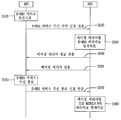
- FIG. 9 is a diagram illustrating a method of setting a paging carrier by reporting E-MBS service reception status information through a location update procedure according to one embodiment of the present specification.
- FIG. 9 shows a method of setting a paging carrier when the carrier to which the E-MBS service is transmitted is a fully configured carrier.
- the UE when the UE enters the idle mode in the connected mode, when receiving the E-MBS service (S910), the UE transmits the E-MBS to the base station through an AAI-DREG-REQ message. Notify that the service is received (S920).
- the paging carrier of the terminal is set to the E-MBS carrier (ie, carrier 3).
- the base station may transmit to the terminal including information indicating that the paging carrier is carrier 3 in the AAI-DREG-RSP message (S930).
- carrier 3 which is an E-MBS carrier, is a fully configured carrier. Therefore, when the terminal terminates the reception of the E-MBS service (S940), the terminal notifies the end of the E-MBS service reception by transmitting a ranging request (AAI-RNG-REQ) message to the base station via the E-MBS carrier ( S950).
- a ranging request AAA-RNG-REQ
- the paging carrier of the terminal is set to a carrier (carrier 2) corresponding to DID modulo N.
- the base station may include information indicating that the paging carrier is carrier 2 in the AAI-RNG-RSP and transmit to the terminal (S960).
- the UE When the UE starts receiving the E-MBS service again through the Carrier 2 (S970), the UE informs the base station of the reception of the E-MBS service by the carrier AAI-RNG-REQ to notify the start of receiving the E-MBS service through the carrier 2 The message is transmitted to the base station (S980).
- the paging carrier is set to 'carrier 3' as described above.
- the base station may include information indicating that the paging carrier is carrier 3 in the AAI-RNG-RSP message and transmit to the terminal (S990).
- FIG. 10 illustrates a paging carrier setup method according to another embodiment of the present disclosure, in particular, when the E-MBS carrier is a partially configured carrier.
- the E-MBS carrier (carrier 3) is a partially configured carrier
- the UE when the UE stops receiving the E-MBS service, the UE corresponds to carrier 2 (DID modulo N carrier).
- the AAI-RNG-REQ message is transmitted to the base station through the E-MBS service reception end.
- the paging carrier is set to carrier 2 (carrier corresponding to DID modulo N).
- the base station may include information indicating that the paging carrier is carrier 2 in the AAI-RNG-RSP message and transmit to the terminal (S1060).
- FIG. 11 is a diagram illustrating a method for setting a paging carrier by reporting an E-MBS service reception status information through a location update procedure by an idle mode terminal according to another embodiment of the present disclosure.
- FIG. 11 illustrates a method for setting a paging carrier when the carrier to which the E-MBS service is transmitted is a fully configured carrier.
- the UE when the UE enters the idle mode in the connected state, the UE transmits an AAI-DREG-REQ message including information indicating that the E-MBS service is not received to the base station, thereby receiving the E-MBS service reception state. Report (S1110, S1120).
- the paging carrier of the idle mode terminal is set to carrier 2 (ie, carrier corresponding to DID modulo N).
- the base station may include information indicating that the paging carrier is carrier 2 in the AAI-DREG-RSP message and transmit it to the terminal (S1130).
- the E-MBS carrier is a fully configured carrier.
- the UE when the UE starts receiving the E-MBS service (S1140), the UE transmits an AAI-RNG-REQ message to the base station through carrier 2 (carrier corresponding to DID modulo N) to start receiving the E-MBS service. Notify (S1150).
- the paging carrier is set to carrier 3 (E-MBS carrier).
- the base station may include information indicating that the paging carrier is carrier 3 in the AAI-RNG-RSP message and transmit it to the terminal (S1160).
- the terminal transmits an AAI-RNG-REQ message to the base station through the carrier 3 to inform the end of the E-MBS service reception (S1180).
- carrier 2 is set as a paging carrier.
- the base station may include information indicating that the paging carrier is carrier 2 in the AAI-RNG-RSP message and transmit it to the terminal (S1190).
- an E-MBS carrier is a partially configured carrier.
- the E-MBS carrier is a partially configured carrier.
- the UE When the UE starts receiving the E-MBS service, the UE notifies the E-MBS service reception by transmitting an AAI-RNG-REQ message to the base station through carrier 2 (carrier corresponding to DID modulo N) (S1250).
- the paging carrier is set to carrier 3 (E-MBS carrier).
- the base station may include information indicating that the paging carrier is carrier 3 in the AAI-RNG-RSP message and transmit it to the terminal (S1260).
- the UE if the UE stops receiving the E-MBS service through Carrier 3 (S1270), the UE transmits through the carrier 2 (ie, a carrier corresponding to DID modulo N) to inform the base station of the end of receiving the E-MBS service.
- the AAI-RNG-REQ including the information indicating the termination of the E-MBS service reception is transmitted to the base station (S1280).
- carrier 2 is set as a paging carrier.
- the base station may include information indicating that the paging carrier is carrier 2 in the AAI-RNG-RSP message and transmit it to the terminal (S1290).
Abstract
본 명세서는 멀티 캐리어 시스템에서, 아이들 모드 단말의 페이징 메시지(paging message) 수신 방법에 있어서, 페이징 리스닝 구간에서 소정의 조건에 해당하는 제 1 캐리어를 통해 페이징 메시지를 네트워크로부터 수신하는 단계; E-MBS 서비스 수신 시작을 알리기 위한 위치 갱신 절차를 나타내는 제어정보를 포함하는 제 1 레인징 요청 메시지를 상기 네트워크로 전송하는 단계; E-MBS 서비스가 전송되는 제 2 캐리어를 페이징 캐리어로 결정하는 단계; 및 상기 결정된 제 2 캐리어를 통해 상기 네트워크로부터 페이징 메시지를 수신하는 단계를 포함하여 이루어진다.
Description
본 명세서는 멀티 캐리어 시스템에 관한 것으로 특히, E-MBS 단말에 관한 페이징 방법 및 장치에 관한 것이다.
16m E-MBS(Enhanced Multicast and Broadcast Service)
진보된 멀티캐스트 및 브로드캐스트 서비스(E-MBS)는 공통의 멀티캐스트 STID(MSTID) 및 FID를 사용하는 사용자들의 그룹에 공통의 하향링크 데이터의 동시 전송을 위한 효율적인 방법을 제공한다. E-MBS 서비스는 단지 하향링크에서만 제공되며, 매크로 다이버시티(macro diversity)를 허용하기 위해 하나의 그룹에 속하는 기지국들 간에 coordination되거나 동기가 맞춰질 수 있다.
각 E-MBS 연결은 서비스 플로우를 위해 QoS 및 트래픽 파라미터들과 함께 제공되는 상기 서비스 플로우와 관련 있다. E-MBS 데이터를 전송하는 서비스 플로우들은 단말이 일반적인 동작을 수행하고 있는 동안 서비스에 참여하는 개별 단말들에게 예로 들어 설명될 수 있다. 그런 설명 동안, 단말은 서비스를 확인하고 서비스 플로우와 관련된 파라미터들을 배운다.
E-MBS 서비스를 제공할 수 있는 각 기지국은 특정 E-MBS 존에 속하며, 하나의 기지국은 다수의 E-MBS 존들에 속할 수 있다. E-MBS 존은 특정 서비스 플로우의 컨텐츠를 전송하기 위해 동일한 MSTID 및 FID가 사용되는 기지국들의 하나의 셋으로서 정의된다. 각각의 E-MBS 존은 고유의 E-MBS 존 ID에 의해 구별된다.
E-MBS 서비스를 지원하는 기지국의 네트워크 상에서 적절한 멀티캐스트 동작을 보장하기 위해, 공통의 E-MBS 컨텐츠 및 서비스를 위해 사용되는 MSTID 및 FID들은 동일한 E-MBS 존 내의 모든 기지국들에게 동일해야 한다.
이것은 특정 서비스에 이미 등록한 단말이 E-MBS 존 내의 다른 기지국과 재등록하거나 상향링크 통신을 수행하지 않고도 E-MBS 존 내에서 끊김없이 E-MBS 전송을 수신하도록 허용한다.
이하에서, 캐리어(Carrier)에 대해 간략히 살펴보기로 한다.
사용자는 정현파 또는 주기적인 펄스파의 진폭, 주파수 및/또는 위상 등에 변조 조작을 하여 전송하고자 하는 정보를 포함할 수 있다. 이때, 정보를 운반하는 역할을 하는 정현파 또는 펄스파를 캐리어라 부른다.
캐리어를 변조하는 방식에는 싱글 캐리어 변조 방식(SCM: Single-Carrier Modulartion scheme) 또는 멀티 캐리어(MCM: Multi-Carrier Modulation scheme) 변조 방식이 있다. 이 중에서 싱글 캐리어 변조방식은 하나의 캐리어에 모든 정보를 실어 변조하는 변조 방식이다.
멀티 캐리어 변조방식은 하나의 캐리어의 전체 대역폭 채널(Channel)을 여러 개의 작은 대역폭을 갖는 부채널(Sub-channel)로 분할하고, 다수의 협대역 부캐리어(Sub-Carrier)를 각 부채널을 통해 다중으로 전송하는 기술을 말한다.
이때, 멀티 캐리어 변조 방식(MCM)을 이용시, 각 부채널은 작은 대역폭으로 인해 평탄한 특성(Flat Channel)로 근사화될 수 있다. 또한, 사용자는 간단한 등화기를 사용하여 채널의 왜곡을 보상할 수 있다. 또한, 멀티 캐리어 변조 방식은 고속 푸리에 변환(FFT)을 이용하여 고속 구현이 가능하다. 즉, 싱글 캐리어 변조방식(SCM)에 비해 고속의 데이터 전송에 유리하다.
기지국 및/또는 단말기의 성능이 발전함에 따라, 기지국 및/또는 단말기에서 제공하거나 사용할 수 있는 주파수 대역폭은 확대되고 있다. 따라서, 본 발명의 실시예들에서는, 하나 이상의 캐리어를 묶어서 사용함(Carrier aggregation)으로써 광대역을 지원하는 멀티 캐리어 시스템을 개시하고 있다.
즉, 이하에서 설명하는 멀티 캐리어 시스템은 앞서 설명한 하나의 캐리어를 나눠 사용하는 멀티 캐리어 변조방식과는 달리, 하나 이상의 캐리어를 묶어서 사용하는 경우를 나타낸다.
다중 대역(Multi-Band; 또는, 멀티 캐리어(Multi-Carrier))을 효율적으로 사용하기 위해 여러 개의 캐리어(예를 들어, 여러 개의 주파수 캐리어(FC: Frequency Carrier))를 하나의 매체 접속 제어(MAC) 엔터티가 관리하는 기술이 제안되어 왔다.
도 1의 (a) 및 (b)는 다중 대역 무선 주파수(RF: Radio Frequency) 기반 신호 송수신 방법을 설명하기 위한 도면이다.
도 1에서, 송신단 및 수신단에서 하나의 매체 접속 제어 계층은 멀티 캐리어를 효율적으로 사용하기 위해 여러 개의 캐리어를 관리할 수 있다. 이때, 멀티 캐리어를 효과적으로 송수신하기 위해, 송신단 및 수신단은 모두 멀티 캐리어를 송수신할 수 있음을 가정한다. 이때, 하나의 매체 접속 제어 계층에서 관리되는 주파수 캐리어(FC: Frequency Carrier)들은 서로 인접할 필요가 없기 때문에 자원 관리 측면에서 유연하다. 즉, 인접 캐리어 집합(Contiguous Aggregation) 또는 불인접 캐리어 집합(Non-contiguous Aggregation) 모두 가능하다.
도 1의 (a) 및 (b)에 있어서 물리계층(PHY)0, 물리계층1, .. 물리계층 n-2, 물리계층 n-1은 본 기술에 따른 다중 대역을 나타내며, 각각의 대역은 미리 정해진 주파수 정책에 따라 특정 서비스를 위해 할당하는 주파수 캐리어(FC) 크기를 가질 수 있다. 예를 들어, 물리계층0 (RF carrier 0)은 일반 FM 라디오 방송을 위해 할당하는 주파수 대역의 크기를 가질 수 있고, 물리계층1 (RF carrier 1)은 휴대 전화 통신을 위해 할당하는 주파수 대역 크기를 가질 수 있다.
이와 같이 각각의 주파수 대역은 각각의 주파수 대역 특성에 따라 서로 다른 주파수 대역 크기를 가질 수 있으나, 이하의 설명에서는 설명의 편의상 각 주파수 캐리어(FC)는 A [MHz] 크기를 가지는 것을 가정한다. 또한, 각각의 주파수 할당 대역은 기저 대역 신호를 각 주파수 대역에서 이용하기 위한 캐리어 주파수로 대표될 수 있는바, 이하에서 각 주파수 할당 대역을 "캐리어 주파수 대역" 또는 혼동이 없는 경우 각 캐리어 주파수 대역을 대표하는 단순히 "캐리어"로 지칭하기로 한다.
또한, 최근 쓰리지피피 엘티이 에이(3GPP LTE-A)에서와 같이 상술한 캐리어를 멀티 캐리어 방식에서 이용되는 서브캐리어(subcarrier)와 구분하기 위해 "성분 캐리어(component carrier)"로 지칭할 수 있다.
이러한 측면에서 상술한 "다중 대역" 방식은 "다중 캐리어(Multi Carrier)" 방식 또는 "캐리어 집합(carrier aggregation)" 방식으로 지칭될 수도 있다.
도 2 (a) 및 (b)는 일반적인 무선통신 시스템에서 다중 반송파가 이용되는 형태의 일례를 나타낸다.
도 2의 (a)를 참조하면, 일반적 기술에서의 다중 반송파는 연속되는 반송파들의 묶음(contiguous carrier aggregation)일 수 있고, 도 2의 (b)와 같이 불연속적인 반송파들의 묶음(non-contiguous carrier aggregation)일 수도 있다. 이러한 반송파들을 결합하는 단위는 일반적 기술인 레거시 시스템(e.g., LTE(Long Term Evolution)-advanced 시스템의 경우 LTE, IEEE 802.16m 시스템의 경우 IEEE 802.16e)의 기본 대역폭 단위이다.
일반적 기술의 다중 반송파 환경에서는 다음과 같은 두 가지 타입의 반송파를 정의한다.
먼저, 제 1반송파(또는 프라이머리 캐리어, primary carrier)는 단말과 기지국의 트래픽, 완전한 물리계층 및 매체접속제어계층 제어정보(full PHY/MAC control information)의 교환이 수행되는 반송파를 말한다. 또한, 주 반송파는 망진입과 같은 단말의 일반적 동작에도 사용될 수 있다. 각 단말은 하나의 셀에서 하나의 주반송파를 갖는다.
그리고, 제 2반송파(또는 세컨더리 캐리어, secondary carrieer) 는 보통 제 1반송파로부터 수신되는 기지국 특정의 할당 명령과 법칙에 따른 트래픽의 교환에 사용될 수 있는 부가적인 반송파를 말한다. 제 2반송파는 멀티 캐리어 동작을 지원하기 위한 제어 시그널링을 포함할 수 있다.
일반적 기술은 위에서 기술한 프라이머리 및 세컨더리 캐리어를 기반으로 다중 반송파(multi-carrier) 시스템의 반송파를 다음과 같이 Fully configured carrier와 Partially configured carrier로 구분할 수 있다.
완전 구성된 캐리어(Fully configured carrier)는 제어 시그널링이 설정되는 반송파를 말한다. 또한, 다중 반송파 운용과 다른 반송파들에 대한 정보 및 파라미터들이 상기 제어채널들에 포함될 수 있다.
부분 구성된 캐리어(Partially configured carrier)는 시분할이중화 하향링크 전송(TDD DL transmission) 또는 주파수분할이중화(FDD) 모드에서 쌍을 이루는 상향링크 캐리어가 없는 하향링크 캐리어에서 하향링크 전송을 지원하기 위한 모든 제어채널이 설정되는 캐리어를 말한다.
일반적으로 단말은 프라이머리 캐리어를 통해서 망 초기 진입(initial network entry)을 수행하며, 기지국과의 등록 요청/응답(AAI_REG-REQ/RSP) 메시지 교환을 통한 등록과정에서 서로의 멀티 캐리어 능력에 대한 정보를 교환할 수 있다.
본 명세서는 아이들 모드 단말의 E-MBS 서비스 수신 여부에 따라, 페이징 메시지가 전송되는 페이징 캐리어가 불분명한 문제점을 해결하기 위한 것으로, 아이들 모드 단말이 E-MBS 서비스 수신 시작 또는 종료를 네트워크로 보고함으로써, E-MBS 서비스 수신 여부에 따라 적절하게 페이징 캐리어를 설정하기 위한 방법을 제공함에 목적이 있다.
또한, 본 명세서는 단말이 아이들 모드로 천이 시, 단말의 E-MBS 서비스 수신 상태 정보를 기지국으로 전송하기 위한 방법을 제공함에 목적이 있다.
또한, 본 명세서는 페이징 캐리어로 네트워크 재진입이 불가능한 경우, 기지국이 네트워크 재진입이 가능한 캐리어를 알려주기 위한 방법을 제공함에 목적이 있다.
본 명세서는 멀티 캐리어 시스템에서, 아이들 모드 단말의 페이징 메시지(paging message) 수신 방법에 있어서, 페이징 리스닝 구간에서 소정의 조건에 해당하는 제 1 캐리어를 통해 페이징 메시지를 네트워크로부터 수신하는 단계; E-MBS 서비스 수신 시작을 알리기 위한 위치 갱신 절차를 나타내는 제어정보를 포함하는 제 1 레인징 요청 메시지를 상기 네트워크로 전송하는 단계; E-MBS 서비스가 전송되는 제 2 캐리어를 페이징 캐리어로 결정하는 단계; 및 상기 결정된 제 2 캐리어를 통해 상기 네트워크로부터 페이징 메시지를 수신하는 단계를 포함하여 이루어진다.
또한, 상기 제 2 캐리어를 페이징 캐리어로 결정하는 단계는 상기 네트워크로부터 E-MBS 서비스가 전송되는 제 2 캐리어를 통해 상기 페이징 메시지가 전송됨을 나타내는 페이징 캐리어 결정 정보를 수신하는 단계를 더 포함하는 것을 특징으로 한다.
또한, 상기 페이징 캐리어 결정 정보는 레인징 응답(RNG-RSP) 메시지를 통해 상기 네트워크로부터 수신되는 것을 특징으로 한다.
또한, E-MBS 서비스 수신 종료를 알리기 위한 위치 갱신 절차를 나타내는 제어정보를 포함하는 제 2 레인징 요청 메시지를 상기 네트워크로 전송하는 단계; 상기 제 1 캐리어를 페이징 캐리어로 결정하는 단계; 및 상기 결정된 제 1 캐리어를 통해 상기 페이징 메시지를 상기 네트워크로부터 수신하는 단계를 포함하여 이루어지는 것을 특징으로 한다.
또한, 상기 제 1 캐리어를 페이징 캐리어로 결정하는 단계는 상기 제 1 캐리어를 통해 상기 페이징 메시지가 전송됨을 나타내는 페이징 캐리어 결정 정보를 포함하는 제 2 레인징 응답 메시지를 상기 네트워크로부터 수신하는 단계를 더 포함하는 것을 특징을 한다.
또한, 상기 소정의 조건은 아이들 모드 단말을 구별하기 위해 사용되는 등록해제 식별자(De-registration Identifier:DID)와 상기 네트워크가 속한 페이징 그룹에서의 캐리어 개수(N)와의 모듈로 연산(DID modulo N)인 것을 특징으로 한다.
또한, 상기 네트워크는 기지국 또는 페이징 제어기(paging controller)인 것을 특징으로 한다.
또한, 상기 제 1 캐리어는 완전 구성된 캐리어(fully configured carrier)이며, 상기 제 2 캐리어는 완전 구성된 캐리어(fully configured carrier) 또는 부분 구성된 캐리어(partially configured carrier)인 것을 특징으로 한다.
또한, 상기 제 2 캐리어가 완전 구성된 캐리어(fully configured carrier)인 경우, 상기 제 1 레인징 요청 메시지는 상기 제 1 캐리어를 통해 전송되고, 상기 제 2 레인징 요청 메시지는 상기 제 2 캐리어를 통해 전송되는 것을 특징으로 한다.
또한, 상기 제 2 캐리어가 부분 구성된 캐리어(partially configured carrier)인 경우, 상기 제 1 및 제 2 레인징 요청 메시지는 상기 제 1 캐리어를 통해 전송되는 것을 특징으로 한다.
또한, E-MBS 서비스 수신 상태 정보를 포함하는 등록해제요청 메시지를 기지국으로 전송하는 단계; 및 상기 등록해제요청 메시지에 대한 응답으로 등록해제응답 메시지를 상기 기지국으로부터 수신하는 단계를 더 포함하여 이루어지는 것을 특징으로 한다.
또한, 상기 E-MBS 서비스 수신 상태 정보는 E-MBS 서비스 수신 시작 또는 종료를 나타내는 정보인 것을 특징으로 한다.
또한, 상기 등록해제요청 메시지는 상기 제 1 캐리어 또는 제 2 캐리어 중 어느 하나의 캐리어를 통해 페이징 메시지의 전송 요청을 지시하는 페이징 캐리어 선택 모드(paging carrier selection mode) 정보를 더 포함하는 것을 특징으로 한다.
또한, 상기 등록해제응답 메시지는 상기 제 1 캐리어 또는 제 2 캐리어 중 어느 하나의 캐리어를 통해 페이징 메시지가 전송됨을 지시하는 페이징 캐리어 선택 모드 정보(paging carrier selection mode)를 더 포함하는 것을 특징으로 한다.
또한, 본 명세서는 멀티 캐리어 시스템에서, 페이징 메시지(paging message)를 수신하기 위한 단말에 있어서, 외부와 무선신호를 송수신하기 위한 무선통신부; 및 상기 무선통신부와 연결되는 제어부를 포함하되, 상기 제어부는 소정의 조건에 해당하는 제 1 캐리어를 통해 페이징 메시지를 네트워크로부터 수신하도록 상기 무선통신부를 제어하며, E-MBS 서비스 수신 시작을 알리기 위한 위치 갱신 절차를 나타내는 제어정보를 포함하는 제 1 레인징 요청 메시지를 상기 네트워크로 전송하도록 상기 무선통신부를 제어하며, E-MBS 서비스가 전송되는 제 2 캐리어를 페이징 캐리어로 결정하며, 상기 결정된 제 2 캐리어를 통해 상기 네트워크로부터 페이징 메시지를 수신하도록 제어하는 것을 특징으로 한다.
또한, 상기 제어부는 E-MBS 서비스 수신 종료를 알리기 위한 위치 갱신 절차를 나타내는 제어정보를 포함하는 제 2 레인징 요청 메시지를 상기 네트워크로 전송하도록 상기 무선통신부를 제어하며, 상기 제 1 캐리어를 페이징 캐리어로 결정하며, 상기 결정된 제 1 캐리어를 통해 상기 페이징 메시지를 상기 네트워크로부터 수신하도록 상기 무선통신부를 제어하는 것을 특징으로 한다.
또한, 상기 소정의 조건은 아이들 모드 단말을 구별하기 위해 사용되는 등록해제 식별자(De-registration Identifier:DID)와 상기 네트워크가 속한 페이징 그룹에서의 캐리어 개수(N)와의 모듈로 연산(DID modulo N)인 것을 특징으로 한다.
또한, 본 명세서는 멀티 캐리어 시스템에서, 아이들 모드 단말의 네트워크 재진입(network re-entry) 방법에 있어서, 페이징 캐리어를 통해 네트워크 재진입 가능 캐리어를 나타내는 캐리어 정보를 포함하는 페이징 메시지를 기지국으로부터 수신하는 단계; 및 상기 캐리어 정보에 기초하여, 상기 기지국으로 네트워크 재진입을 수행하는 단계를 포함하되, 상기 페이징 캐리어는 부분 구성된 캐리어(partially configured carrier)인 것을 특징으로 한다.
또한, 상기 캐리어 정보는 물리 캐리어 인덱스(physical carrier index)인 것을 특징으로 한다.
또한, 상기 네트워크 재진입 가능 캐리어가 다수인 경우, 상기 캐리어 정보 중 어느 하나의 캐리어를 결정하는 단계를 더 포함하는 것을 특징으로 한다.
또한, 상기 어느 하나의 캐리어를 결정하는 단계는 랜덤하게(randomly) 또는 아이들 모드 단말 식별자(DID)와 네트워크 재진입 가능 캐리어 개수와의 모듈로 연산을 수행하는 것을 특징으로 한다.
또한, 상기 페이징 캐리어는 E-MBS가 전송되는 캐리어이거나 아이들 모드 단말 식별자와 페이징 그룹에서의 캐리어 개수와의 모듈로 연산 결과 값에 해당하는 캐리어인 것을 특징으로 한다.
본 명세서는 멀티 캐리어를 지원하는 시스템에서 아이들 모드 단말이 E-MBS서비스 수신 시작 또는 종료를 네트워크(기지국 또는 페이징 제어기(paging controller))에게 알림으로써, 단말의 페이징 캐리어를 바르게 설정할 수 있는 효과가 있다.
또한, 본 명세서는 기지국이 단말로 네트워크 재진입이 가능한(network reentry) 캐리어를 알려줌으로써, 불필요하게 단말이 cell reselection하는 과정을 줄일 수 있는 효과가 있다.
도 1의 (a) 및 (b)는 다중 대역 무선 주파수(RF: Radio Frequency) 기반 신호 송수신 방법을 설명하기 위한 도면이다.
도 2 (a) 및 (b)는 일반적인 무선통신 시스템에서 다중 반송파가 이용되는 형태의 일례를 나타낸다.
도 3은 무선통신 시스템을 나타낸 블록도이다.
도 4는 무선 접속 시스템에서의 단말과 기지국의 내부 블록도를 나타낸다.
도 5는 본 명세서의 제 1 실시 예에 따른 E-MBS 서비스 수신 상태(시작 또는 종료) 보고에 따라 단말의 페이징 메시지 수신 방법을 나타낸 흐름도이다.
도 6은 본 명세서의 제 1 실시 예에 따른 E-MBS 서비스 수신 상태 보고를 위해 위치 갱신 절차(location update process)를 수행함으로써, 페이징 캐리어를 업데이트하는 방법을 나타낸 흐름도이다.
도 7 (a) 및 (b)는 본 명세서의 제 1 실시 예의 또 다른 일 예로서, E-MBS 서비스 수신 상태 보고를 위해 위치 갱신 절차(location update process)를 수행함으로써, 페이징 캐리어 업데이트 방법을 나타낸 흐름도이다.
도 8은 본 명세서의 제 2 실시 예에 따른 단말이 기지국과 등록해제하는 과정에서 E-MBS 서비스 수신 상태 정보를 기지국으로 전송하는 방법을 나타낸 일 예이다.
도 9 내지 도 12는 각각 본 명세서의 실시 예들에 따른 E-MBS 단말의 페이징 캐리어를 설정하기 위한 전체적인 흐름도를 나타낸다.
이하의 기술은 CDMA(Code Division Multiple Access), FDMA(Frequency Division Multiple Access), TDMA(Time Division Multiple Access), OFDMA(Orthogonal Frequency Division Multiple Access), SC-FDMA(Single Carrier Frequency Division Multiple Access) 등과 같은 다양한 무선 통신 시스템에 사용될 수 있다. CDMA는 UTRA(Universal Terrestrial Radio Access)나 CDMA2000과 같은 무선 기술(radio technology)로 구현될 수 있다. TDMA는 GSM(Global System for Mobile communications)/GPRS(General Packet Radio Service)/EDGE(Enhanced Data Rates for GSM Evolution)와 같은 무선 기술로 구현될 수 있다. OFDMA는 IEEE 802.11(Wi-Fi), IEEE 802.16(WiMAX), IEEE 802-20, E-UTRA(Evolved UTRA) 등과 같은 무선 기술로 구현될 수 있다. IEEE 802.16m은 IEEE 802.16e의 진화로, IEEE 802.16e에 기반한 시스템과의 하위 호환성(backward compatibility)를 제공한다.
UTRA는 UMTS(Universal Mobile Telecommunications System)의 일부이다. 3GPP(3rd Generation Partnership Project) LTE(Long Term Evolution)은 E-UTRA(Evolved-UMTS Terrestrial Radio Access)를 사용하는 E-UMTS(Evolved UMTS)의 일부로써, 하향링크에서 OFDMA를 채용하고 상향링크에서 SC-FDMA를 채용한다. LTE-A(Advanced)는 3GPP LTE의 진화이다.
설명을 명확하게 하기 위해, IEEE 802.16m을 위주로 기술하지만 본 발명의 기술적 사상이 이에 제한되는 것은 아니다.
도 3은 무선통신 시스템을 나타낸 블록도이다.
무선통신 시스템은 음성, 패킷 데이터 등과 같은 다양한 통신 서비스를 제공하기 위해 널리 배치된다.
도 3을 참조하면, 무선통신 시스템은 단말(10; Mobile station, MS) 및 기지국(20; Base Station, BS)을 포함한다. 단말(10)은 고정되거나 이동성을 가질 수 있으며, UE(User Equipment), UT(User Terminal), SS(Subscriber Station), 무선기기(Wireless Device),AMS(Advanced Mobile Station) 등 다른 용어로 불릴 수 있다.
기지국(20)은 일반적으로 단말(10)과 통신하는 고정된 지점(fixed station)을 말하며, 노드B(NodeB), BTS(Base Transceiver System), 액세스 포인트(Access Point) 등 다른 용어로 불릴 수 있다. 하나의 기지국(20)에는 하나 이상의 셀이 존재할 수 있다.
무선통신 시스템은 OFDM(Orthogonal Frequency Division Multiplexing) /OFDMA(Orthogonal Frequency Division Multiple Access) 기반 시스템일 수 있다.
OFDM은 다수의 직교 부반송파를 이용한다. OFDM은 IFFT(inverse fast Fourier Transform)과 FFT(fast Fourier Transform) 사이의 직교성 특성을 이용한다. 전송기에서 데이터는 IFFT를 수행하여 전송한다. 수신기에서 수신신호에 대해 FFT를 수행하여 원래 데이터를 복원한다. 전송기는 다중 부반송파들을 결합하기 위해 IFFT를 사용하고, 다중 부반송파들을 분리하기 위해 수신기는 대응하는 FFT를 사용한다.
또한, 슬롯(slot)은 최소한의 가능한 데이터 할당 유닛으로, 시간과 서브채널(subchannel)로 정의된다. 상향링크에서 서브채널은 다수의 타일(tile)로 구성될 수 있다(construct). 서브 채널은 6 타일로 구성되고, 상향링크에서 하나의 버스트는 3 OFDM 심벌과 1 서브채널로 구성될 수 있다.
PUSC(Partial Usage of Subchannels) 순열(permutation)에 있어서, 각 타일은 3 OFDM 심벌 상에서 4 인접하는 부반송파를 포함할 수 있다. 선택적으로, 각 타일은 3 OFDM 심벌 상에서 3 인접하는 부반송파를 포함할 수 있다. 빈(bin)은 OFDM 심벌 상에서 9 인접하는(contiguous) 부반송파를 포함한다. 밴드(band)는 빈의 4 행(row)의 그룹을 말하고, AMC(Adaptive modulation and Coding) 서브채널은 동일한 밴드에서 6 인접하는 빈들로 구성된다.
도 4는 무선 접속 시스템에서의 단말과 기지국의 내부 블록도를 나타낸다.
단말(10)은 제어부(11), 메모리(12) 및 무선통신(RF)부(13)을 포함한다.
또한, 단말은 디스플레이부(display unit), 사용자 인터페이스부(user interface unit)등도 포함한다.
제어부(11)는 제안된 기능, 과정 및/또는 방법을 구현한다. 무선 인터페이스 프로토콜의 계층들은 제어부(11)에 의해 구현될 수 있다.
메모리(12)는 제어부(11)와 연결되어, 무선 통신 수행을 위한 프로토콜이나 파라미터를 저장한다. 즉, 단말 구동 시스템, 애플리케이션 및 일반적인 파일을 저장한다.
RF부(13)는 제어부(11)와 연결되어, 무선 신호를 송신 및/또는 수신한다.
추가적으로, 디스플레이부는 단말의 여러 정보를 디스플레이하며, LCD(Liquid Crystal Display), OLED(Organic Light Emitting Diodes) 등 잘 알려진 요소를 사용할 수 있다. 사용자 인터페이스부는 키패드나 터치 스크린 등 잘 알려진 사용자 인터페이스의 조합으로 이루어질 수 있다.
기지국(20)은 제어부(21), 메모리(22) 및 무선통신(RF)부(radio frequency unit)(23)을 포함한다.
제어부(21)는 제안된 기능, 과정 및/또는 방법을 구현한다. 무선 인터페이스 프로토콜의 계층들은 제어부(21)에 의해 구현될 수 있다.
메모리(22)는 제어부(21)와 연결되어, 무선 통신 수행을 위한 프로토콜이나 파라미터를 저장한다.
RF부(23)는 제어부(21)와 연결되어, 무선 신호를 송신 및/또는 수신한다.
제어부(11, 21)는 ASIC(application-specific integrated circuit), 다른 칩셋, 논리 회로 및/또는 데이터 처리 장치를 포함할 수 있다. 메모리(12,22)는 ROM(read-only memory), RAM(random access memory), 플래쉬 메모리, 메모리 카드, 저장 매체 및/또는 다른 저장 장치를 포함할 수 있다. RF부(13,23)은 무선 신호를 처리하기 위한 베이스밴드 회로를 포함할 수 있다. 실시 예가 소프트웨어로 구현될 때, 상술한 기법은 상술한 기능을 수행하는 모듈(과정, 기능 등)로 구현될 수 있다. 모듈은 메모리(12,22)에 저장되고, 제어부(11, 21)에 의해 실행될 수 있다.
메모리(12,22)는 제어부(11, 21) 내부 또는 외부에 있을 수 있고, 잘 알려진 다양한 수단으로 제어부(11, 21)와 연결될 수 있다.
이하에서, E-MBS 동작과 관련된 내용에 대해 간략히 살펴보기로 한다.
E-MBS 전송 모드
E-MBS 트래픽을 전송하는 모드에는 Non-macro diversity transmission mode와 Macro diversity transmission mode 두 가지가 있다.
1. 비 매크로 다이버시티 모드(Non-macro diversity mode)
Non-macro diversity mode는 같은 존에 있는 기지국들이 같은 frame에서 전송을 coordination하는 것으로서, macro diversity mode를 이용하지 못할 때 사용된다. 같은 E-MBS Zone에 속한 모든 기지국들은 같은 frame에서 같은 contents를 나르는 SDU를 전송한다. 이러한 SDU는 같은 frame에서 MPDU들에 맵핑된다. 이는 같은 SDU fragments, 같은 fragment sequence number, 같은 fragment size를 의미한다. 이는 같은 AMS들이 같은 Zone안의 ABS들로부터 E-MBS 전송을 받는 것을 가능하게 해준다.
2. 매크로 다이버시티 모드(Macro diversity mode)
Macro diversity mode는 한 존의 모든 ABS들이 E-MBS 전송을 동기화하는 것을 의미하며, 이는 한 존에서 모든 ABS들이 같은 데이터를 같은 시점에 같은 자원을 사용하여 전송한다는 것을 의미한다. 이는 E-MBS 전송에서 macro diversity gain을 얻는 효과를 가져온다. 자세하게, 같은 존 안의 모든 ABS들은 다음과 같은 정보들을 공유한다.
1) E-MBS Zone ID, MSTID & FID, MSI, and Packet Classification Rule parameter(s)
2) Transmission PHY parameters, MCS associated with each E-MBS Burst including FEC Type, Modulation Type, and Repetition Coding
3) Mapping of SDUs to PDU (order of the SDUs and fragments) including Extended Headers )
4) Mapping of PDUs to bursts
5) Order of bursts in the zone/region
6) E-MBS MAP construction
E-MBS 프로토콜 특징과 기능
1. E-MBS 설정 지시자(E-MBS Configuration Indicator)
E-MBS 설정에 관한 정보는 AAI_E-MBS-CFG 메시지라고 불리는 MAC control 메시지를 사용하는 E-MBS에 관심이 있는 단말들에게 주기적으로 전송된다.
E-MBS 설정 지시자는 하향링크 물리 자원에서 E-MBS 트래픽과 E-MBS 동작을 위해 필요한 추가적인 정보들을 위해 확보된 자원들을 명시한다.
2. E-MBS 존 설정(E-MBS Zone Configuration)
다른 E-MBS ID들과 FID들은 동일한 E-MBS 서비스 플로우에 대한 다른 E-MBS 존에서 사용될 수 있다. E-MBS_ZONE_ID는 E-MBS 서비스 플로우에 대한 E-MBS ID 및 FID가 유효한 서비스 지역을 나타내기 위해 사용된다. E-MBS를 지원하는 기지국은 기지국이 속하는 E-MBS 존 ID가 E-MBS CFG 메시지에 포함된다. E-MBS 존 ID는 '0'이 될 수 없다.
기지국이 E-MBS 존 ID에 대한 연결 수립을 위해 AAI_DSA 메시지를 전송할 때, E-MBS 존 ID는 DSA 메시지 내에 부호화될 것이다. 하나의 기지국은 다른 E-MBS 서비스들을 위해 다수의 E-MBS 존 ID를 가질 수 있다.
3. E-MBS 스케쥴링 구간(E-MBS Scheduling Interval:MSI)
각각의 E-MBS 존에 대해 하나의 MSI가 있다. 여기서 MSI는 접속 네트워크가 MSI 구간의 시작에 앞서 MBS 존과 관련된 스트림들에 대한 트래픽을 스케쥴할 수 있는 연속적인 슈퍼-프레임들의 개수를 말한다.
MSI는 몇 개의 슈퍼프레임들의 간격과 NMSI로 표시되는 MSI 구간의 길이를 가질 수 있으며, E-MBS의 특별한 사용에 의존한다.MSI는 NMSI=4, 8, 16 및 32 슈퍼프레임 길이가 될 수 있다. E-MBS 맵 메시지는 하나의 전체 MSI 동안 E-MBS 존과 관련된 E-MBS 데이터의 매핑 주소를 가진다. E-MBS 맵 메시지는 하나의 MSI 내에 주어진 스트림에 대한 하나의 전송 상황을 충분히 정의하도록 사용되기 위해 구성된다. MSI 길이의 표시는 SCD 메시지를 통해 전송된다. 슈퍼프레임 번호, SFH로부터의 NSuperframe 및 SCD 메시지로부터의 NMSI를 사용함으로써, 단말은 하기와 같이 MSI의 시작을 계산한다.
MSI는 MSI의 NSuperframe이 하기 조건을 만족하는 슈퍼프레임에서 시작된다.
NSuperframe Modulo NMSI==0
단말은 단지 사용자가 선택한 컨텐츠와 관련된 E-MBS 데이터 버스트들을 복조할 수 있다. 단말은 복조될 E-MBS 데이터 버스트가 있는지 여부를 확인하기 위해 각 MSI 구간에서 깨어난다.
아이들 모드(Idle Mode)
멀티 캐리어 시스템에서 페이징 그룹 정보 메시지(PGID_Info message)는 모든 완전 구성된 캐리어들에서 전송된다. 단말에 대한 페이징 광고 메시지(AAI_PAG-ADV message)는 완전 구성된 캐리어들 중 단지 하나의 캐리어를 통해 전송된다. 아이들 모드 단말은 단말의 페이징 리스닝 구간에 페이징 메시지를 모니터링하기 위한 캐리어 인덱스를 결정한다. 페이징 리스닝 구간에 전송되는 페이징 메시지는 다음과 같은 규칙을 사용하여 전송된다.
Paging carrier index = DID modulo N
N의 값은 아이들 모드 단말에 대한 페이징 메시지를 전송하기 위해 사용되는 기지국에서의 페이징 그룹에서의 캐리어 개수이다. 또한, DID(De-registration Identifier)는 아이들 모드 단말을 구별하기 위한 식별자를 의미한다.
페이징 캐리어 인덱스는 기지국에서 페이징 메시지를 전송하기 위해 사용되는 캐리어들의 물리적인 캐리어 인덱스의 오름차순에 해당한다.
페이징 캐리어 지시 비트는 해당 캐리어가 페이징 캐리어인지 아닌지를 명시하기 위해 사용된다. 페이징 캐리어 지시가 '1'인 경우, 해당 캐리어는 페이징 캐리어를 나타낸다. 다른 캐리어들의 페이징 캐리어 지시들은 페이징 그룹 정보 메시지에 포함되고 이웃 광고 메시지(AAI_NBR-ADV) 또는 멀티 캐리어 광고 메시지(AAI_MC-ADV)에 포함될 수 있다.
아이들 모드 단말이 새로운 기지국으로 이동할 때, 새로운 기지국의 SFH 변경 카운트(change count)가 이웃 광고 메시지를 통해 수신된 정보와 동일하다고 결정할 때, 단말은 페이징 캐리어 지시가 이웃 광고 메시지 내에 포함되어 있으면 이웃 광고 메시지를 통해 수신된 페이징 캐리어 지시를 사용할 수 있다.
페이징 광고 메시지는 슈퍼 프레임 내에서의 두 번째 서브 프레임으로부터 시작하는 하나 이상의 프레임을 통해 전송된다.
E-MBS 단말에 대해 페이징 광고 메시지는 E-MBS를 위한 전용 캐리어와 동일한 캐리어를 통해 전송될 수 있다.
상기에서 살핀 것처럼, E-MBS 서비스 수신 없이 멀티 캐리어 모드로 동작하는 단말들이 아이들 모드로 천이 시, 네트워크로부터 페이징 메시지(paging message)를 수신하기 위한 페이징 캐리어(paging carrier)는 상기의 DID를 N으로 modulo 취해서 나온 값으로 결정되고, paging carrier index에 해당되는 carrier를 통해서 paging message를 네트워크로부터 수신하기를 기다릴 것이다. 즉, 아이들 모드 단말이 E-MBS service를 받고자 할 때, E-MBS 구성 정보를 이미 가지고 있다면, 단말은 이전에 받았던 E-MBS 구성 정보를 이용하여 E-MBS 서비스를 수신한다.
하지만, 단말이 아이들 모드에서 기지국과 아무런 신호 전송 없이 이전 E-MBS 정보를 가지고 E-MBS 서비스를 받는다면, 기지국은 E-MBS 서비스를 받기 전의 paging carrier로 단말에게 페이징을 수행할 것이고, 단말은 E-MBS 캐리어로 페이징 메시지가 전송된다고 판단할 것이다.
따라서, 네트워크는 E-MBS 서비스를 가입한 모든 단말들의 paging 정보들을 E-MBS carrier로 전송하는 방법이 있을 수 있다. 이 경우, E-MBS 서비스를 가입한 모든 단말들이 실제로 E-MBS 서비스를 받고 있는지 상관없이 하나의 paging group 안에서 E-MBS를 가입한 모든 단말들의 paging 정보를 하나의 E-MBS carrier로 전송해야 되기 때문에, 이는 E-MBS carrier의 paging overhead를 증가시킬 수 있다.
이하, 본 명세서에서 제안하는 E-MBS 캐리어에 불필요하게 paging overhead가 몰리는 것을 방지하기 위해, 단말이 E-MBS 서비스 수신 상태(시작 또는 종료)를 네트워크에 보고함으로써, 단말의 페이징 캐리어를 적절하게 설정하는 방법에 대해 실시 예들을 통해 구체적으로 살펴보기로 한다.
제 1 실시 예
제 1 실시 예는 아이들 모드 단말의 E-MBS 서비스 수신 상태(시작 또는 종료)보고를 통해 기지국의 페이징 메시지 전송 방법을 제공한다.
즉, 제 1 실시 예는 E-MBS 서비스에 가입한 아이들 모드 단말이더라도 E-MBS 서비스를 수신하지 않는 경우, 페이징 메시지가 E-MBS 서비스가 전송되는 캐리어('E-MBS 캐리어' 또는 '제 2 캐리어')가 아닌 DID modulo N에 해당하는 캐리어('제 1 캐리어')를 통해 전송되도록 단말의 페이징 캐리어를 설정하는 방법을 제공한다.
도 5는 본 명세서의 제 1 실시 예에 따른 E-MBS 서비스 수신 상태(시작 또는 종료) 보고에 따라 단말의 페이징 메시지 수신 방법을 나타낸 흐름도이다.
도 5를 참조하면, 아이들 모드(Idle mode) 단말은 기지국으로부터 E-MBS 서비스를 수신하기 시작하는 경우(S510), E-MBS 서비스 수신 시작을 알리는 신호를 네트워크로 전송한다(S520). 여기서, 네트워크는 기지국 또는 페이징 제어기(paging controller)일 수 있다.
또한, 상기 E-MBS 서비스 수신 시작을 알리는 신호는 단말의 위치 갱신 절차(location update process)를 통해 전송될 수 있다. 위치 갱신 절차를 통해 E-MBS 서비스 수신 시작을 알리는 방법에 대해서는 이하에서 구체적으로 살펴보기로 한다.
네트워크가 상기 단말로부터 E-MBS 서비스 수신 시작을 알리는 신호를 받은 경우, 네트워크는 상기 아이들 모드 단말의 페이징 캐리어 인덱스(paging carrier index)를 E-MBS 서비스가 제공되는 캐리어로 업데이트 해 준다(S530).
여기서, 네트워크는 업데이트된 페이징 캐리어 인덱스 즉, E-MBS 캐리어 인덱스를 아이들 모드 단말에게 전송할 수 있다(S540). 이 경우, 아이들 모드 단말은 E-MBS 캐리어를 통해 네트워크로부터 페이징 메시지를 수신하게 된다(S550).
이후, E-MBS 서비스를 수신하고 있는 아이들 모드 단말이 E-MBS 서비스 수신을 종료하는 경우(S560), 상기 아이들 모드 단말은 E-MBS 서비스 수신 종료를 알리는 신호를 네트워크로 전송한다(S570).
여기서, 네트워크가 상기 아이들 모드 단말로부터 E-MBS 서비스 수신 종료를 알리는 신호를 수신하는 경우, 상기 네트워크는 상기 단말의 페이징 캐리어 인덱스(paging carrier index)를 상기 아이들 모드 단말의 등록해제식별자(DID)와 N(기지국이 속하는 페이징 그룹당 캐리어 개수) 값의 모듈로 연산을 통해(DID modulo N)나온 값의 캐리어 인덱스로 설정해준다(S580).
도 6은 본 명세서의 제 1 실시 예에 따른 E-MBS 서비스 수신 상태 보고를 위해 위치 갱신 절차(location update process)를 수행함으로써, 페이징 캐리어를 업데이트하는 방법을 나타낸 흐름도이다.
도 6을 참조하면, 아이들 모드 단말은 E-MBS 서비스를 수신하는 경우(S610,S620), E-MBS 서비스 수신 시작을 알리기 위한 위치 갱신 절차임을 나타내는 제어정보를 포함하는 레인징 요청 메시지를 기지국으로 전송한다(S630).
여기서, 상기 제어정보는 레인징 목적을 지시하는 레인징 목적 지시 정보(Ranging purpose indication)이다.
일 예로, E-MBS 서비스 수신을 시작하는 경우, 상기 레인징 목적 지시 정보는 '0x1110'로 설정될 수 있다.
즉, 네트워크는 아이들 모드 단말로부터 레인징 목적 지시 정보가 '0x1110'로 설정된 레인징 요청 메시지를 수신하는 경우, 상기 단말의 페이징 캐리어를 E-MBS 서비스가 전송되는 캐리어로 설정한다(S640). 여기서, 상기 E-MBS 서비스가 전송되는 캐리어는 E-MBS 서비스 전송을 위한 전용 캐리어(Dedicated carrier)일 수 있다.
여기서, 네트워크는(기지국 또는 페이징 제어기) 상기 단말의 위치 갱신(location update)에 대한 응답을 할 때, 레인징 응답 메시지에 상기 설정된 페이징 캐리어 인덱스(paging carrier index)를 포함하여 단말에게 페이징 캐리어를 알려줄 수 있다(S650).
여기서, 아이들 모드 단말로 전송되는 레인징 응답 메시지(AAI_RNG-RSP)에 상기 paging carrier index가 포함되지 않으면, 단말은 자동으로 E-MBS 캐리어를 paging carrier로 설정한다.
이후, 아이들 모드 단말이 E-MBS 서비스 수신을 종료하는 경우(S660), 네트워크(기지국 또는 페이징 제어기)로 E-MBS 서비스 수신 종료를 알리기 위한 위치 갱신 절차임을 나타내는 제어정보를 포함하는 레인징 요청 메시지를 전송한다(S670).
여기서, 상기 제어정보는 레인징 목적 지시 정보이며, E-MBS 서비스 수신 종료를 알리기 위한 위치 갱신일 경우, 상기 레인징 목적 지시 정보는 일 예로, '0x1111'로 설정될 수 있다.
즉, 기지국이 아이들 모드 단말로부터 E-MBS 서비스 수신 종료를 알리는 위치 갱신 신호(일 예로, Ranging purpose indication = '0x1111')를 수신하는 경우, 기지국은 상기 아이들 모드 단말의 페이징 캐리어를 아이들 모드 단말의 DID를 N(기지국에서의 페이징 그룹마다 캐리어 개수)으로 모듈로(modulo) 연산한 값으로 설정한다(S680).
여기서, 기지국은 상기 단말의 위치 갱신(location update)에 대한 응답을 할 때, 레인징 응답 메시지(AAI_RNG-RSP message)에 상기 DID modulo N에 해당하는 페이징 캐리어 인덱스(paging carrier index)를 상기 아이들 모드 단말로 알려줄 수 있다(S690).
또한, 단말은 E-MBS 서비스를 수신하는 경우, 네트워크로 E-MBS 서비스 수신 시작을 알리기 위해, 기존에 E-MBS 서비스 플로우 관리 인코딩 갱신(service flow management encoding update)을 위해서 정의된 레인징 목적 지시(ranging purpose indication) 정보 값 (일 예로, '0x0110')을 사용할 수도 있다.
도 7 (a) 및 (b)는 본 명세서의 제 1 실시 예의 또 다른 일 예로서, E-MBS 서비스 수신 상태 보고를 위해 위치 갱신 절차(location update process)를 수행함으로써, 페이징 캐리어 업데이트 방법을 나타낸 흐름도이다.
도 7 (a)를 참조하면, 아이들 모드 단말이 E-MBS service 수신 시작을 원하는 경우, 현재 서비스를 하고 있는 E-MBS Zone에 대한 E-MBS service flow management encoding 정보(일 예로, E-MBS Zone ID, E-MBS IDs and FIDs, physical carrier index, ...)를 가지고 있지 않으면, 단말은 기지국으로부터 E-MBS service flow management encoding 정보를 획득하기 위해서 레인징 목적 지시 정보가 일 예로, '0b0110'로 설정된 레인징 요청 메시지를 기지국으로 전송한다(S710~S730).
기지국은 레인징 요청 메시지에 대한 응답으로 E-MBS service flow management encoding 정보를 포함한 레인징 응답 메시지(AAI_RNG-RSP message)를 상기 단말로 전송한다(S750).
여기서, 기지국은 페이징 캐리어를 E-MBS 캐리어로 설정한다(S740). 또한, 상기 설정된 페이징 캐리어를 상기 레인징 응답 메시지에 포함하여 아이들 모드 단말로 전송할 수 있다.
도 7 (b)는 S730 단계에서, 레인징 목적 지시 정보가 '0x1111'인 경우를 나타낸다.
하기 표 1은 본 명세서의 제 1 실시 예에 따른 레인징 요청 메시지(RNG-REQ message) 포맷의 일 예를 나타낸다.
표 1
| M/O | Attributes / Array of attributes | Size (bits) | Value / Note | Conditions |
| O | Ranging purpose Indication | 8 | 0b0000 = Initial network entry. …0b1110= Location update process to notify the Paging controller/ABS of the start of receiving E-MBS service. In this case the paging carrier is updated to the carrier which provides E-MBS. 0b1111= Location update process to notify the Paging controller/ABS of the end of receiving E-MBS service. In this case the paging carrier of this AMS is updated to the paging carrier index calculated by the following equation. Paging carrier index = DID modulo N | |
상기 표 1을 참조하면, 레인징 목적 지시 필드 값이 '0b1110'으로 설정된 경우, E-MBS 서비스 수신 시작을 알리기 위한 위치 갱신 절차임을, '0b1111'로 설정된 경우, E-MBS 서비스 수신 종료를 알리기 위한 위치 갱신 절차임을 나타내는 것을 볼 수 있다.
하기 표 2는 본 명세서의 제 1 실시 예에 따른 레인징 요청 메시지(RNG-REQ message) 포맷의 또 다른 일 예를 나타낸다.
표 2
| M/O | Attributes / Array of attributes | Size (bits) | Value / Note | Conditions |
| O | Ranging purpose Indication | 8 | 0b0000 = Initial network entry. … 0b0110= Either location update for updating service flow management encordings for E-MBS flows or location update to notify the Paging controller/ABS of the start of receiving E-MBS service. In case of the latter the paging carrier is updated to the carrier for E-MBS. 0b1111 (or 0b1110) = Location update process to notify the Paging controller/ABS of the end of receiving E-MBS service. In this case the paging carrier of this AMS is updated to the paging carrier index calculated by the following equation. Paging carrier index = DID modulo N | |
상기 표 2를 참조하면, 레인징 목적 지시 필드 값이 '0b0110'으로 설정된 경우, E-MBS 서비스 수신 시작을 알리기 위한 위치 갱신 수행임을 나타내는 것을 볼 수 있다. 또한, 레인징 목적 지시 필드 값이 '0b1111'로 설정된 경우, E-MBS 서비스 수신 종료를 알리기 위한 위치 갱신 수행임을 나타낸다.
하기 표 3은 본 명세서의 제 1 실시 예에 따른 레인징 응답 메시지(RNG-RSP message) 포맷의 일 예를 나타낸다.
표 3
| M/O | Attributes / Array of attributes | Size (bits) | Value / Note | Conditions |
| O | Ranging response | 8 | 0x00= Success of Location Update 0x01= Failure of Location Update 0x02 = Reserved 0x03=Success of location update and DL traffic pending 0x04 = Allow AMS's DCR mode initiation request or DCR mode extension request 0x05 = Reject AMS's DCR mode initiation request or DCR mode extension request 0x06~0xF: Reserved | |
| Paging carrier index | 8 | Indicates the physical carrier index where the AAI_PAG-ADV for the AMS is transmitted. | ||
상기 표 3을 참조하면, 레인징 응답 메시지는 아이들 모드 단말에 대한 페이징 광고 메시지가 전송되는 물리 캐리어 인덱스를 지시하는 페이징 캐리어 인덱스 필드를 포함하는 것을 볼 수 있다.
또한, 본 명세서의 또 다른 일 실시 예에 따르면, 아이들 모드 단말은 레인징 목적 지시 정보(Ranging purpose Indication) 중 어느 하나가 페이징 캐리어를 요청하기 위한 위치 갱신 수행임을 나타내도록 하는 레인징 요청 메시지(AAI-RNG-REQ message)를 기지국으로 전송할 수 있다.
기지국은 상기 아이들 모드 단말로부터 페이징 캐리어 요청을 위한 레인징 목적 지시 정보를 포함하는 레인징 요청 메시지를 수신하면, 상기 아이들 모드 단말로 페이징 캐리어 인덱스를 포함하는 레인징 응답 메시지를 전송한다.
하기 표 4는 본 명세서의 일 실시 예에 따른 페이징 캐리어 요청을 위한 위치 갱신 수행임을 나타내는 레인징 목적 지시 정보를 포함하는 레인징 요청 메시지 포맷의 일 예를 나타낸다.
표 4
| Attributes / Array of attributes | Size (bits) | Value / Note | Conditions |
| Ranging purpose Indication | 8 | 0b0000 = Initial network entry. …0b1111 (or 0b1110) = Location update process for requesting the change of paging carrier | |
| If (Ranging purpose Indication == 0b1111) { | |||
| Preferred Paging carrier type | 1 | 0: The carrier where the E-MBS service is provided. It implicitly indicates the start of receiving E-MBS service 1: The carrier with the carrier index = DID modulo N It implicitly indicates the end of receiving E-MBS service | |
| } | |||
상기 표 4를 참조하면, 선호 페이징 캐리어 타입(Preferred Paging carrier type) 필드는 단말이 기지국으로 요청하는 페이징 캐리어가 E-MBS 캐리어인지 DID modulo N에 해당하는 캐리어인지를 지시한다.
일 예로, 선호 페이징 캐리어 타입 필드 값이 '0'인 경우, 페이징 캐리어를 E-MBS 캐리어로 요청하며, 이는 아이들 모드 단말이 E-MBS 서비스를 수신하기 시작했다는 것을 나타낸다.
또한, 선호 페이징 캐리어 타입 필드 값이 '1'인 경우, 페이징 캐리어를 DID modulo N에 해당하는 캐리어로 요청하며, 이는 아이들 모드 단말이 E-MBS 서비스 수신을 종료하였음을 나타낸다.
하기 표 5는 본 명세서의 일 실시 예에 따른 페이징 캐리어 요청을 위한 위치 갱신 수행임을 나타내는 레인징 목적 지시 정보를 포함하는 레인징 요청(RNG-REQ) 메시지 포맷의 또 다른 일 예를 나타낸다.
표 5
| Attributes / Array of attributes | Size (bits) | Value / Note | Conditions |
| Ranging purpose Indication | 8 | 0b0000 = Initial network entry. …0b1111 (or 0b1110) = Location update process for reporting the status of E-MBS data reception | |
| If (Ranging purpose Indication == 0b1111) { | |||
| E- MBS status | 1 | 0: The start of receiving E-MBS service. The paging carrier shall be set to the carrier which E-MBS data is sent. 1: The end of receiving E-MBS service. The paging carrier is the carrier with the carrier index = DID modulo N. | |
| } | |||
상기 표 5를 참조하면, E-MBS 상태 필드 값이 '0'인 경우, 단말이 E-MBS 서비스를 받기 시작했다는 것을 가리키고, paging carrier는 E-MBS carrier로 설정된다.
또한, E-MBS 상태 필드 값이 '1'인 경우, E-MBS 서비스 수신이 종료되었다는 것을 가리키고, paging carrier는 DID modulo N의 캐리어로 설정된다.
상기 표 5에서 E-MBS 상태 필드 값은 ranging purpose indication 이 0b1111로 설정될 경우에 포함되는 것으로 예를 들었다. 하지만, E-MBS 서비스의 시작이나 종료를 나타내기 위한 E-MBS 상태 정보 필드는 ranging purpose가 0b1111 이외의 다른 값으로 설정된 경우에도 AAI-RNG-REQ에 포함되어 기지국에게 관련 정보를 알려줄 수 있다. 예를 들어, ranging purpose indication이 normal location update(0b0011)를 가리킬 때, optional 필드로서 E-MBS status 필드가 AAI-RNG-REQ메시지에 포함되어 기지국에 전달될 수 있다.
이하에서, 본 명세서의 또 다른 실시 예에 따른 네트워크(기지국 또는 페이징 제어기)가 아이들 모드 단말에게 페이징 메시지(paging message)를 전송하고, 단말이 상황에 따라서 페이징 캐리어(paging carrier)를 선택하는 방법에 대해 간략히 살펴보기로 한다.
네트워크(기지국 또는 페이징 제어기)는 E-MBS가 전송되는 캐리어('E-MBS carrier')에서는 E-MBS 서비스를 수신하는 아이들 모드 단말들에 대한 paging message(AAI_PAG-ADV) 뿐만 아니라 E-MBS 서비스를 수신하지 않는 단말들에 대한 paging message를 전송한다. 여기서, E-MBS 서비스를 받지 않는 단말들은 단말의 DID를 N으로 modulo 하여 구한 paging carrier index에 해당하는 paging carrier를 결정한 Idle mode 단말들을 말한다.
즉, E-MBS carrier를 통해 기지국이 속한 모든 paging group에 속한 모든 Idle mode 단말들에 대한 paging message를 전송하며, Idle mode 단말에 대한 paging message를 DID modulo N을 한 값에 의해 결정된 paging carrier로 전송한다.
아이들 모드 단말이 E-MBS 서비스를 받고 있을 경우, 단말은 paging carrier를 E-MBS 서비스가 전송되는 캐리어로 선택하고, E-MBS carrier를 통해 네트워크로부터 paging message를 수신한다.
이후, E-MBS 서비스를 수신하고 있던 아이들 모드 단말이 E-MBS 서비스 수신을 종료하였을 경우, 단말은 paging carrier를 E-MBS carrier에서 DID modulo N을 한 값에 의해 결정된 carrier로 설정한다. 상기 DID modulo N에 해당하는 carrier를 통해 네트워크로부터 paging message를 수신한다.
또한, 본 명세서의 또 다른 실시 예로서, E-MBS dedicated carrier로 E-MBS 서비스를 수신하고 있는 아이들 모드 단말에 대해서 Paging message를 전송하는 또 다른 방법으로, 기지국은 E-MBS 서비스를 수신하는 단말들에 대해서는 E-MBS carrier 및 DID modulo N을 하여 나온 paging carrier index 에 해당하는 carrier모두를 통해서 페이징 광고(AAI_PAG-ADV) 메시지를 전송한다.
이하에서, 단말이 연결 모드에서 아이들 모드로 천이 시, E-MBS 서비스 수신 상태(시작 또는 종료) 보고를 통해 네트워크로부터 페이징 메시지를 수신하는 방법에 대해 구체적으로 살펴보기로 한다.
제 2 실시 예
제 2 실시 예는 단말이 연결 상태(Connected state)에서 아이들 모드(Idle mode)로 천이하는 과정에서, 단말의 E-MBS 서비스 수신 상태 보고를 통한 네트워크로부터 페이징 메시지를 수신하는 방법을 제공한다.
즉, 제 2 실시 예는 단말이 등록해제(De-registration)하는 과정에서, 단말은 기지국에게 현재 자신이 E-MBS 서비스를 수신하고 있는지에 대한 정보를 알릴 수 있다.
여기서, 단말이 아이들 모드로 천이할 때, 현재 E-MBS 서비스를 수신하고 있다면 기지국과 단말은 단말의 paging carrier를 E-MBS 가 전송되는 carrier로 설정하고, 단말이 E-MBS 서비스를 받고 있지 않다면, 기지국과 단말은 단말의 paging carrier를 DID modulo N 에 해당하는 캐리어로 설정한다.
도 8은 본 명세서의 제 2 실시 예에 따른 단말이 기지국과 등록해제하는 과정에서 E-MBS 서비스 수신 상태 정보를 기지국으로 전송하는 방법을 나타낸 일 예이다.
도 8을 참조하면, 단말은 E-MBS 서비스를 수신하거나 수신하지 않을 수 있다(S810).
단말은 아이들 모드로 천이 시, E-MBS 서비스 수신 상태 정보를 포함하는 등록해제요청(DREG-REQ) 메시지를 기지국으로 전송한다(S820). 여기서, E-MBS 서비스 수신 상태 정보는 현재 단말이 E-MBS 서비스를 받고 있는지에 대한 여부 즉, E-MBS 서비스 수신 시작 또는 종료를 기지국에게 알리는 정보를 말한다.
하기 표 6은 본 명세서의 제 2 실시 예에 따른 E-MBS 서비스 수신 상태 정보를 포함하는 등록해제요청 메시지(AAI_DREG-REQ message) 포맷의 일 예를 나타낸다.
표 6
| M/O | Attributes/Array of attributes | Size(bits) | Value/Notes | Conditions |
| M | E-MBS reception status | 1 | 단말이 현재 E-MBS를 수신하고 있는지에 대한 여부를 나타냄 0b0: 단말이 E-MBS 수신 하지 않음 0b1: 단말은 현재 E-MBS를 수신하고 있음 |
또한, 상기 등록해제요청 메시지는 단말이 아이들 모드(idle mode)로 들어갈 때, paging carrier를 선택하기 위해서 기지국에게 단말이 사용하기를 원하는 페이징 캐리어를 나타내는 페이징 캐리어 선택 모드(paging carrier selection mode)에 대한 정보를 더 포함할 수 있다.
하기 표 7은 본 명세서의 일 실시 예에 따른 paging carrier selection mode정보를 포함하는 등록해제요청 메시지(AAI_DREG-REQ message) 포맷의 일 예를 나타낸다.
표 7
| M/O | Attributes/Array of atteributes | Size(bits) | Value/Notes |
| M | Paging carrier selection mode | 1 | Indicates whether the paging carrier index for the AMS which currently receives the E-MBS service is configured based on the equation "DID modulo N" or to the carrier where the E-MBS service is provided. 0b0: The paging carrier index is set to the equation "DID modulo N". 0b1: The paging carrier index for AMS is set to the carrier where the E-MBS service is provided. |
상기 표 7을 참조하면, 단말이 E-MBS 서비스를 받고 있을 때 아이들 모드로 천이 시, 어떤 paging carrier mode로 받을 지에 대한 정보를 기지국에게 올려준다.
일 예로, paging carrier selection mode 값이 '0b0'로 설정된 경우, E-MBS 서비스를 받고 있을 때 단말이 DID modulo N에 대한 paging carrier index로 paging 메시지를 받기를 원하는 것을 나타낸다.
또한, paging carrier selection mode 값이 '0b1'로 설정된 경우, E-MBS 서비스를 받고 있을 때 단말이 E-MBS 서비스가 전송되는 carrier로 paging message를 받기를 원한다는 것을 나타낸다.
다음, 기지국은 단말로부터 E-MBS 서비스 수신 상태 정보 및 paging carrier selection mode 정보 중 적어도 하나를 포함하는 등록해제요청 메시지를 수신한 경우, 상기 등록해제요청 메시지에 대한 응답으로 등록해제응답(AAI_DREG-RSP) 메시지를 단말로 전송한다(S830).
여기서, 상기 등록해제응답 메시지는 페이징 캐리어 선택 모드 정보를 포함한다. 상기 페이징 캐리어 선택 모드 정보는 기지국이 단말로부터 AAI_DREG-REQ를 받았을 때, paging carrier selection mode 필드의 설정 값을 고려하여 단말이 사용할 paging carrier selection mode를 알려주는 정보를 나타낸다.
하기 표 8은 본 명세서의 일 실시 예에 따른 paging carrier selection mode정보를 포함하는 등록해제응답 메시지(AAI_DREG-REQ message) 포맷의 일 예를 나타낸다.
표 8
| M/O | Attributes/Array of attributes | Size(bits) | Value/Notes |
| M | Paging carrier selection mode | 1 | Indicates whether the paging carrier index for AMS is the index based on the equation "DID modulo N" or the carrier where the E-MBS service is provided. 0b0: The paging carrier index is set to the equation "DID modulo N". 0b1: The paging carrier index for AMS is set to the carrier where the E-MBS service is provided. |
상기 표 8을 참조하면, 기지국이 '0b0'으로 설정된 paging carrier selection mode를 포함하는 등록해제응답(AAI_DREG-RSP) 메시지를 단말로 전송한 경우, 단말은 E-MBS 서비스를 받을 때의 paging carrier index가 DID modulo N으로 설정된다고 판단하고, Idle mode 상태에서 E-MBS 수신의 시작과 종료를 기지국에게 보고하지 않아도 된다.
또한, 단말은 아이들 모드 천이 시, 상기에서 살핀 E-MBS 서비스 수신 상태정보 및 E-MBS 수신 시 paging carrier 선택 모드 정보 모두를 등록해제요청 메시지에 포함하여 기지국으로 전송할 수 있다.
하기 표 9는 E-MBS 서비스 수신 상태(시작 또는 종료) 정보 및 paging carrier 선택 모드 정보를 포함하는 등록해제요청 메시지 포맷의 일 예를 나타낸 표이다.
표 9
| M/O | Attributes/Array of attributes | Size(bits) | Value/Notes | Conditions |
| M | Paging carrier selection mode | 1 | Indicates whether the paging carrier index for the AMS which currently receives the E-MBS service is configured based on the equation "DID modulo N" or to the carrier where the E-MBS service is provided. 0b0: The paging carrier index is set to the equation "DID modulo N". 0b1: The paging carrier index for AMS is set to the carrier where the E-MBS service is provided. | |
| M | E-MBS reception status | 1 | 단말이 현재 E-MBS를 수신하고 있는지에 대한 여부를 나타냄 0b0: 단말이 E-MBS 수신 하지 않음 0b1: 단말은 현재 E-MBS를 수신하고 있음 | It will be present when Paging carrier selection mode is 0b1 |
상기 표 9를 참조하면, E-MBS 단말을 위한 paging carrier index가 E-MBS가 전송되는 carrier 일 경우에만 단말은 E-MBS 서비스 수신 상태를 보고 한다. 만약 기지국이 paging carrier index를 E-MBS가 전송되는 carrier로 설정할 경우, 단말은 E-MBS 서비스 수신의 시작과 종료 시에 기지국에게 이를 알리는 과정을 수행한다.
상기 실시 예 1에서 살핀 것처럼, 위치 갱신 절차(Location update procedure)를 통해서 단말은 기지국에게 E-MBS 서비스 수신의 시작과 종료를 알릴 수 있다.
하기 표 10은 본 명세서의 일 실시 예에 따른 E-MBS 서비스 수신 상태 정보를 암묵적으로 함축하는 페이징 캐리어 선택 모드 정보를 포함하는 등록해제요청 메시지 포맷의 일 예를 나타낸다.
표 10
| M/O | Attributes/Array of attributes | Size(bits) | Value/Notes |
| M | Paging carrier selection mode | 1 | Indicates whether the paging carrier index for the AMS which currently receives the E-MBS service is configured based on the equation "DID modulo N" or to the carrier where the E-MBS service is provided. 0b0: The paging carrier index is set to the equation "DID modulo N". This value shall be generally chosen by when the AMS does not receive E-MBS service currently. 0b1: The paging carrier index for AMS is set to the carrier where the E-MBS service is provided. This value shall be generally chosen by AMS when the ABS receives E-MBS service currently. This implicitly indicates that the AMS receives E-MBS service currently. |
상기 표 10을 참조하면, 상기 Paging carrier selection mode 필드는 E-MBS 수신 상태 정보를 암묵적으로 함축할 수 있다. 일 예로, Paging carrier selection mode 필드 값이 '0b0'인 경우, 단말이 E-MBS 서비스를 현재 받고 있지 않은 상태에서 Idle mode로 들어간다는 것을, '0b1'은 현재 단말이 E-MBS 서비스를 받고 있다는 것을 나타낸다.
이하에서는 본 명세서의 또 다른 일 실시 예로서, 아이들 모드 단말이 페이징 캐리어를 통해 네트워크로부터 페이징 메시지를 수신한 경우, 기지국으로 네트워크 재진입(network re-entry)을 수행하는 방법에 대해 하기 실시 예 3을 통해 구체적으로 살펴보기로 한다.
제 3 실시 예
제 3 실시 예는 페이징 캐리어를 통해 네트워크 재진입 과정을 수행할 수 없는 경우(일 예로, 페이징 캐리어가 partially configured carrier 또는 cell bar가 '1'로 설정된 경우), 단말이 기지국으로 네트워크 재진입 과정을 수행하는 방법을 제공한다.
먼저, 기지국은 E-MBS 단말들(즉, DSA(Dynamic Service Addition)를 수행한 후, DSD(Dynamic Service Deletion)를 하지 않은 단말들)에게 paging 메시지를 전송할 때, 우선 E-MBS 가 전송되는 carrier로 paging message를 전송한 후 해당 단말이 일정 시간(paging cycle)내에 network re-entry를 하지 못하면, 기지국은 DID modulo N 로 설정한 값으로 단말의 paging 메시지를 전송한다.
DID modulo N의 값으로 단말의 paging carrier를 설정한 후, 해당 carrier 를 통해서 단말을 깨우는 paging message를 보낸 후 단말이 일정 시간 내에 단말이 network re-entry를 하지 못하면 기지국은 E-MBS carrier를 통해서 paging message를 전송한다.
아이들 모드 단말이 paging carrier를 통해서 자신을 깨우는 페이징 메시지를 수신한 경우, 상기 paging carrier로 네트워크 재진입을 할 수 없을 때(예를 들어, Cell bar=1 또는 paging이 전송되는 carrier가 부분 구성된(partially configured) carrier일 경우), 단말은 paging carrier가 아닌 다른 carrier로 네트워크 진입하는 과정을 수행해야 한다.
이하에서, 단말이 네트워크 진입을 빠르게 수행하기 위해 기지국이 단말에게 네트워크 진입이 가능한 캐리어를 알려주는 방법들(방법 1 ~ 5)에 대해 살펴보기로 한다.
1. 방법 1
방법 1은 셀 재탐색(cell reselection) 과정이다.
단말이 기지국으로부터 페이징 메시지(paging message)를 수신한 캐리어가 부분 구성된 캐리어(partially configured carrier) 인 경우, 단말은 셀 재탐색(cell reselection) 과정을 수행한다. 즉, 단말은 셀 재탐색 과정을 통해 네트워크 재진입을 위한 캐리어를 결정한 후, 결정된 캐리어를 통해 네트워크 재진입 과정을 수행하게 된다.
2. 방법 2
방법 2는 DID modulo N에 해당하는 캐리어로 네트워크 재진입(network re-entry)을 수행하는 과정이다.
단말이 페이징 메시지(paging message)가 전송되는 페이징 캐리어로 네트워크 진입을 할 수 없는 경우, 단말은 DID modulo N에 해당하는 캐리어로 네트워크 재진입 과정(network re-entry procedure)를 수행한다.
여기서, 상기 페이징 캐리어로 네트워크 진입을 할 수 없는 경우는 페이징 캐리어가 partially configured carrier이거나 또는 cell bar == 1인 경우일 수 있다.
일 예로, 단말이 E-MBS 서비스에 가입하여 partially configured carrier인 E-MBS dedicated carrier로 paging message를 네트워크로부터 수신하고 있을 때, 단말은 DID(De-registeration Identifier) modulo N(number of carrier per PGID in an ABS)에 해당하는 carrier를 네트워크 재진입을 위한 carrier로 설정한다.
E-MBS carrier를 통해서 paging된 단말은 DID modulo N에 해당하는 carrier로 network re-entry를 수행한다.
Partially configured carrier를 통해서 E-MBS를 받고 있는 단말은 idle mode로 들어갈 때(등록해제과정을 통해) 또는 페이징 그룹 정보(PGID), 멀티 캐리어 광고(MC-ADV), 이웃 광고(NBR-ADV) 메시지를 통해서 상기 N 값을 수신한다. 따라서, 단말은 DID modulo N을 통해서 network re-entry carrier를 계산할 수 있다.
3. 방법 3
방법 3은 기지국이 단말로 네트워크 진입 가능한 캐리어 정보를 전송하는 방법이다.
기지국이 paging 하는 단말에게 네트워크 진입을 다른 캐리어로 수행하도록 명령하기 위해서 해당 단말이 네트워크 진입을 할 수 있는 physical carrier index 정보를 paging message에 포함시켜 단말로 전송한다. 이때, 상기 페이징 메시지에 포함된 paging carrier index 정보는 상기 paging message에 포함된 모든 단말들에게 동일하게 적용되거나 각각 다르게 적용될 수 있다.
하기 표 11은 본 명세서의 일 실시 예에 따른 페이징 광고 메시지(PAG-ADV message) 포맷의 일 예를 나타낸다.
표 11
| Field | Size | Description | Condition |
| Paging_Group_IDs bitmap | L | L equals theNum_PGIDs in PGIDInfomessage | |
| For (i=0; i<M; i++) { | M equals the number ofbits inPaging_Group_IDs bitmapwhose bit is set to1. | ||
| For (j=0; j<Num_AMSs;j++) { | Num_AMSs indicates the number ofpaged AMSs in a corresponding paginggroup1..32 | ||
| Deregistration Identifier | 18 | Used to indicate Deregistration ID forthe AMS to be paged (DeregistrationIdentifier and Paging Cycle are used toidentify each paged AMS)0..218-1 | |
| MAC Address Hash | 24 | used to identify the AMS to be paged | |
| Paging Cycle | |||
| Action code | |||
| Physical carrier index | 6 | 단말이 network reentry를 수행할 carrier index를 가리킨다. 단말은 이 carrier index가 가리키는 carrier로 network reentry를 수행한다. | 기지국이 multiple carrier를 지원하고, paging message가 partially configured carrier로 전송될 때 또는 paging message가 전송되는 carrier의 cell bar가 1로 설정되었을 때, physical carrier index가 포함 |
| } | |||
| } |
여기서, 기지국은 단말에게 네트워크 진입이 가능한 하나 이상의 carrier index 정보를 paging message에 포함시켜 보낼 수 있다.
즉, 기지국이 지원하는 multi-carrier 정보들 중 network re-entry가 가능한 carrier 정보들을 모두 포함시켜서 단말로 전송한다.
하기 표 12는 네트워크 재진입이 가능한 캐리어 정보들을 모두 포함하는 페이징 광고 메시지 포맷의 일 예를 나타낸다.
표 12
| Field | Size | Description | Condition |
| Paging_Group_IDs bitmap | L | L equals theNum_PGIDs in PGIDInfomessage | |
| For (i=0; i<M; i++) { | M equals the number ofbits inPaging_Group_IDs bitmapwhose bit is set to1. | ||
| For (j=0; j<Num_AMSs;j++) { | Num_AMSs indicates the number ofpaged AMSs in a corresponding paginggroup1..32 | ||
| Deregistration Identifier | 18 | Used to indicate Deregistration ID forthe AMS to be paged (DeregistrationIdentifier and Paging Cycle are used toidentify each paged AMS)0..218-1 | |
| MAC Address Hash | 24 | used to identify the AMS to be paged | |
| Paging Cycle | |||
| Action code | |||
| } | |||
| } | |||
| For (j=0; j<Num_CarrierIndexes; j++) { | N um_CarrierIndexes 은 network reentry가 가능한 carrier들의 수를 가리킨다. | ||
| Physical carrier index | 6 | 이 페이징 메시지를 받은 모든 단말들이 network reentry를 수행할 carrier index를 가리킨다. 단말은 이 carrier index가 가리키는 carrier로 network reentry를 수행한다. | 기지국이 multiple carrier를지원하고, paging message가 partially configured carrier로 전송될 때 또는 paging message가 전송되는 carrier의 cell bar가 1로 설정되었을 때, physical carrier index가 포함 |
| } | |||
기지국으로부터 하나 이상의 physical carrier index를 포함하는 페이징 메시지를 수신한 단말은 상기 수신된 physical carrier index들 중 자신이 network re-entry가 가능한 carrier를 선택한 후, 상기 선택된 carrier로 network reentry를 수행한다.
여기서, 상기 선택된(즉, 네트워크 재진입이 가능한) 캐리어가 하나인 경우에는 해당 carrier로 network re-entry를 수행한다.
만약, 상기 선택된(즉, 네트워크 재진입이 가능한) carrier가 두 개 이상일 경우, 단말은 하기와 같은 방법들 중 어느 하나를 이용하여 하나의 network re-entry carrier를 선택한 후, 기지국으로 상기 선택된 캐리어를 통해 기지국과 network re-entry를 수행한다.
(1) 단말은 네트워크 엔트리가 가능한 캐리어들 중에서 임의로(randomly) 하나를 선택하여 기지국과 network reentry를 수행한다.
(2) 네트워크 엔트리가 가능한 캐리어 개수를 M이라고 할 때, 단말은 DID modulo M 연산 결과 값에 해당하는 인덱스의 캐리어로 network reentry를 수행한다.
또한, 기지국이 전송하는 상기 네트워크 재진입이 가능한 physical carrier index 정보는 페이징 되는 각각의 단말에 다르게 적용될 수 있다. 이 경우, 페이징 광고(PAG-ADV) 메시지 포맷의 일 예는 하기 표 13과 같이 구성될 수 있다.
표 13
| Field | Size | Description | Condition |
| Paging_Group_IDs bitmap | L | L equals theNum_PGIDs in PGIDInfomessage | |
| For (i=0; i<M; i++) { | M equals the number ofbits inPaging_Group_IDs bitmapwhose bit is set to1. | ||
| For (j=0; j<Num_AMSs;j++) { | Num_AMSs indicates the number ofpaged AMSs in a corresponding paginggroup1..32 | ||
| Deregistration Identifier | 18 | Used to indicate Deregistration ID forthe AMS to be paged (DeregistrationIdentifier and Paging Cycle are used toidentify each paged AMS)0..218-1 | |
| MAC Address Hash | 24 | used to identify the AMS to be paged | |
| Paging Cycle | |||
| Action code | |||
| Physical carrier index | 6 | 단말이 network reentry를 수행할 carrier index를 가리킨다. 단말은 이 carrier index가 가리키는 carrier로 network reentry를 수행한다. | 기지국이 multiple carrier를 지원하고, paging message가 partially configured carrier로 전송될 때 또는 paging message가 전송되는 carrier의 cell bar가 1로 설정되었을 때, physical carrier index가 포함 |
| } | |||
| } |
상기 표 13을 참조하면, 각각의 단말 별로 network re-entry를 위한 carrier index를 알려줌에 의해서 특정 carrier의 오버헤드를 줄일 수 있다.
4. 방법 4
기지국이 단말로 paging carrier를 통해 페이징 메시지(paging message)를 전송할 때, 상기 페이징 캐리어로의 네트워크 엔트리(network entry)를 금지할 때에, 기지국은 페이징 메시지(paging message)에 셀 바(cell bar) 정보를 포함시켜 단말로 전송한다.
여기서, 일 예로, 상기 Cell bar가 '1'로 설정되어 있으면, 해당 carrier로 network reentry가 불가능하다는 것을 나타내고, 단말은 DID modulo N에 해당하는 carrier로 network re-entry를 수행한다.
하기 표 14는 cell bar 정보를 포함하는 페이징 광고(AAI_PAG-ADV) 메시지 포맷의 일 예를 나타낸다.
표 14
| Syntax | Size | Description |
| AAI_PAG-ADV message () { | ||
| Cell bar | 1 | AAI_PAG-ADV가 Physical carrier index를 포함하는지에 대한 여부를 나타냄. 페이징 되는 단말들이 현재 carrier에 네트워크 진입이 가능하면 0으로 설정될 것이다. 즉, 현재 캐리어로 페이징 되는 단말이 네트워크 진입을 할 수 없을 때, 1로 설정된다. 1: Physical carrier index가 포함됨. |
| } |
5. 방법 5
방법 5는 위치 갱신 절차(location update procedure)를 통해 네트워크 진입이 가능한 캐리어를 단말로 알려주는 방법이다.
페이징 되는 carrier가 완전 구성된(fully configured) carrier이지만 해당 carrier로 네트워크 진입이 불가능하다고 판단될 때(일 예로, Cell bar = 1), 단말은 location update 메시지(AAI_RNG-REQ)를 통해서 기지국으로 네트워크 진입이 가능한 physical carrier index를 요청한다.
이 경우, 단말은 AAI-RNG-REQ 메시지에 네트워크 재진입(network reentry)을 위한 선호 캐리어 인덱스(Preferred carrier index) 정보를 같이 포함시켜 기지국으로 전송할 수 있다.
Physical carrier index를 요청하는 AAI_RNG-REQ 메시지를 단말로부터 수신한 기지국은 레인징 응답(AAI_RNG-RSP) 메시지에 단말이 네트워크 진입을 가능하게 할 physical carrier index를 포함시켜 단말로 전송한다.
이 경우, 상기 레인징 요청 메시지(AAI-RNG-REQ)에 선호 캐리어 인덱스 정보(Preferred carrier index)가 포함되어 있으면, 기지국이 단말로 전송하는 physical carrier index는 상기 단말이 요청한 선호 캐리어 인덱스(preferred carrier index)로 설정될 수 있다.
기지국으로부터 상기 레인징 응답(AAI_RNG-RSP) 메시지를 수신한 단말은 상기 레인징 응답 메시지에 포함된 physical carrier index로 네트워크 진입을 수행한다.
만약, AAI-RNG-REQ 메시지에 preferred carrier 정보를 포함시키고, AAI-RNG-RSP에 physical carrier index가 포함되어 있지 않으면, 단말은 레인징 요청 메시지에 포함된 선호 캐리어 인덱스(preferred carrier index)에 해당하는 carrier로 network re-entry를 수행한다.
하기 표 15는 선호 캐리어 인덱스 정보를 포함하는 레인징 요청 메시지 포맷의 일 예를 나타낸다.
표 15
| Attributes / Array of attributes | Size (bits) | Value / Note | Conditions |
| Ranging purpose Indication | 8 | 0b0000 = Initial network entry. …0b1110 (or 0b01111) = Location update process to request the physical carrier index where the AMS performs the network entry. | |
| For (j=0; j<Num_CarrierIndexes; j++) { | Num_CarrierIndexes 은 단말이 network reentry가 가능한 carrier들의 수를 가리킨다. | ||
| Preferred carrier index | 6 | 단말이 network reentry를 하기 위해 선호하는 carrier index | |
| } | |||
하기 표 16은 네트워크 엔트리가 가능한 캐리어 인덱스 정보를 포함하는 레인징 응답(REG-RSP) 메시지 포맷의 일 예를 나타낸다.
표 16
| Attributes / Array of attributes | Size (bits) | Value / Note | Conditions |
| Physical carrier index | 8 | Indicates the physical carrier index where the AMS performs the network entry. | |
이하에서, 상기 실시 예 1 내지 3에서 살펴본 내용들을 바탕으로 단말이 위치 갱신 절차를 통해서 E-MBS 서비스 수신 상태를 기지국으로 보고함으로써, 단말과 기지국(또는 paging controller) 간 단말의 paging carrier를 설정하는 방법에 대해 도 9 내지 도 12를 참조하여 살펴본다.
도 9 및 도 10은 단말이 E-MBS 서비스를 수신하고 있는 중 아이들 모드로 천이할 때, 페이징 캐리어 설정 방법을, 도 11 및 도 12는 단말이 E-MBS 서비스 수신하지 않고 아이들 모드로 천이 후, E-MBS 서비스 수신 여부에 따라 페이징 캐리어를 설정하는 방법을 나타낸다.
또한, 도 9 내지 도 12는 단말이 연결 모드에서 아이들 모드로 천이 시 즉, 단말은 기지국과 등록해제과정을 통해 단말의 E-MBS 서비스 수신 상태를 기지국으로 알릴 수 있다.
먼저, 도 9는 본 명세서의 일 실시 예에 따른 위치 갱신(location update) 절차를 통해 E-MBS 서비스 수신 상태 정보를 보고함으로써 페이징 캐리어를 설정하는 방법을 나타낸 도이다.
도 9는 E-MBS 서비스가 전송되는 캐리어가 완전 구성된 캐리어인 경우의 페이징 캐리어 설정 방법을 나타낸다.
도 9를 참조하면, 단말이 연결 모드에서 아이들 모드로 들어갈 때, E-MBS 서비스를 수신하고 있는 경우(S910), 단말은 등록해제요청(AAI-DREG-REQ) 메시지를 통해서 기지국으로 E-MBS 서비스를 수신하고 있음을 알린다(S920).
여기서, 단말은 E-MBS 서비스를 수신하고 있기 때문에, 단말의 paging carrier는 E-MBS carrier(즉, carrier 3)로 설정된다. 이때, 기지국은 등록해제응답(AAI-DREG-RSP) 메시지에 paging carrier가 carrier 3임을 나타내는 정보를 포함하여 단말에게 전송할 수 있다(S930).
도 9에 도시된 바와 같이, E-MBS carrier인 carrier 3은 완전 구성된 캐리어(fully configured carrier)이다. 따라서, 단말이 E-MBS 서비스 수신을 종료할 때(S940), 단말은 E-MBS carrier를 통해서 기지국에게 레인징 요청(AAI-RNG-REQ) 메시지를 전송하여 E-MBS 서비스 수신 종료를 알린다(S950).
여기서, E-MBS 서비스 수신이 종료되었기 때문에, 단말의 페이징 캐리어(paging carrier)는 DID modulo N에 해당하는 carrier(carrier 2)로 설정된다.
이때, 기지국은 AAI-RNG-RSP에 paging carrier가 carrier 2임을 나타내는 정보를 포함시켜 단말에게 전송할 수 있다(S960).
단말은 상기 Carrier 2를 통해 다시 E-MBS 서비스 수신을 시작하는 경우(S970), 단말은 E-MBS 서비스 수신을 기지국으로 알리기 위해서 carrier 2를 통해 E-MBS 서비스 수신 시작을 알리는 AAI-RNG-REQ 메시지를 기지국에게 전송한다(S980).
여기서, paging carrier는 상기에서와 같이, 'carrier 3'으로 설정된다. 이때, 기지국은 AAI-RNG-RSP 메시지에 paging carrier가 carrier 3임을 나타내는 정보를 포함시켜 단말에게 전송할 수 있다(S990).
도 10은 본 명세서의 또 다른 실시 예에 따른 페이징 캐리어 설정 방법으로서 특히, E-MBS 캐리어가 부분 구성된 캐리어인 경우를 나타낸다.
S1010 내지 S1040 및 S1070 내지 1090은 도 9의 S910 내지 S940 및 S970 내지 990 단계와 동일하므로, 동일한 부분에 대한 설명은 생략하고 차이가 나는 부분에 대해서만 설명하기로 한다.
도 10을 참조하면, E-MBS carrier(carrier 3)는 부분 구성된 캐리어(partially configured carrier)이기 때문에, 단말은 E-MBS 서비스 수신을 중단할 때, 단말은 carrier 2(DID modulo N에 해당하는 carrier)를 통해서 기지국으로 AAI-RNG-REQ 메시지를 전송하여 E-MBS 서비스 수신 종료를 알린다(S1050).
여기서, 페이징 캐리어(paging carrier)는 carrier 2(DID modulo N에 해당하는 carrier)로 설정된다. 이때, 기지국은 AAI-RNG-RSP 메시지에 paging carrier가 carrier 2임을 나타내는 정보를 포함시켜 단말에게 전송할 수도 있다(S1060).
도 11은 본 명세서의 또 다른 실시 예에 따른 아이들 모드 단말이 위치 갱신 절차를 통해 E-MBS 서비스 수신 상태 정보를 보고함으로써 페이징 캐리어를 설정하는 방법을 나타낸 도이다.
도 11은 E-MBS 서비스가 전송되는 캐리어가 완전 구성된 캐리어인 경우의 페이징 캐리어 설정 방법을 나타낸다.
도 11을 참조하면, 단말은 연결 상태에서 아이들 모드로 들어갈 때, E-MBS 서비스를 수신하지 않음을 나타내는 정보를 포함하는 AAI-DREG-REQ 메시지를 기지국으로 전송함으로써, E-MBS 서비스 수신 상태를 보고한다(S1110, S1120).
아이들 모드 단말은 E-MBS 서비스를 수신하지 않기 때문에, 아이들 모드 단말의 paging carrier는 carrier 2(즉, DID modulo N에 해당하는 carrier)로 설정된다. 이때, 기지국은 AAI-DREG-RSP 메시지에 paging carrier가 carrier 2임을 나타내는 정보를 포함시켜 단말에게 전송할 수도 있다(S1130).
도 11에 도시된 바와 같이, E-MBS carrier는 fully configured carrier이다.
이후, 단말이 E-MBS 서비스 수신을 시작하는 경우(S1140), 단말은 carrier 2 (DID modulo N에 해당하는 carrier)를 통해서 기지국으로 AAI-RNG-REQ 메시지를 전송하여 E-MBS 서비스 수신 시작을 알린다(S1150). 이 경우, paging carrier는 carrier 3(E-MBS carrier)으로 설정된다. 이때, 기지국은 AAI-RNG-RSP 메시지에 paging carrier가 carrier 3임을 나타내는 정보를 포함시켜 단말에게 전송할 수도 있다(S1160).
이후, 단말이 E-MBS 서비스 수신을 종료하는 경우(S1170), 단말은 E-MBS 서비스 수신 종료를 알리기 위해 상기 carrier 3을 통해 AAI-RNG-REQ 메시지를 기지국으로 전송한다(S1180). 이 경우, carrier 2가 paging carrier로 설정된다. 이때, 기지국은 AAI-RNG-RSP 메시지에 paging carrier가 carrier 2임을 나타내는 정보를 포함시켜 단말에게 전송할 수도 있다(S1190).
도 12는 본 명세서의 또 다른 실시 예에 따른 페이징 캐리어 설정 방법으로서 특히, E-MBS 캐리어가 부분 구성된 캐리어인 경우를 나타낸다.
S1210 내지 S1270은 도 11의 S1110 내지 S1170 단계와 동일하므로, 동일한 부분에 대한 설명은 생략하고 차이가 나는 부분에 대해서만 설명하기로 한다.
도 12에 도시된 바와 같이, E-MBS carrier는 partially configured carrier이다.
단말이 E-MBS 서비스 수신을 시작하는 경우, 단말은 carrier 2(DID modulo N에 해당하는 carrier)를 통해서 기지국으로 AAI-RNG-REQ 메시지를 전송하여 E-MBS 서비스 수신을 알린다(S1250). 여기서, paging carrier 는 carrier 3(E-MBS carrier)으로 설정된다. 이때, 기지국은 AAI-RNG-RSP 메시지에 paging carrier가 carrier 3임을 나타내는 정보를 포함시켜 단말에게 전송할 수도 있다(S1260).
이후, 단말이 Carrier 3을 통해 수신하고 있는 E-MBS 서비스를 중지하면(S1270), 단말은 기지국으로 E-MBS 서비스 수신 종료를 알리기 위해서 carrier 2(즉, DID modulo N에 해당하는 carrier)를 통해 E-MBS 서비스 수신 종료를 나타내는 정보를 포함한 AAI-RNG-REQ를 기지국에게 전송한다(S1280).
이 경우, carrier 2가 paging carrier로 설정된다. 이때, 기지국은 AAI-RNG-RSP 메시지에 paging carrier가 carrier 2임을 나타내는 정보를 포함시켜 단말에게 전송할 수도 있다(S1290).
Claims (26)
- 멀티 캐리어 시스템에서, 아이들 모드 단말의 페이징 메시지(paging message) 수신 방법에 있어서,페이징 리스닝 구간에서 소정의 조건에 해당하는 제 1 캐리어를 통해 페이징 메시지를 네트워크로부터 수신하는 단계;E-MBS 서비스 수신 시작을 알리기 위한 위치 갱신 절차를 나타내는 제어정보를 포함하는 제 1 레인징 요청 메시지를 상기 네트워크로 전송하는 단계;E-MBS 서비스가 전송되는 제 2 캐리어를 페이징 캐리어로 결정하는 단계; 및상기 결정된 제 2 캐리어를 통해 상기 네트워크로부터 페이징 메시지를 수신하는 단계를 포함하여 이루어지는 것을 특징으로 하는 방법.
- 제 1항에 있어서,상기 제 2 캐리어를 페이징 캐리어로 결정하는 단계는,상기 네트워크로부터 E-MBS 서비스가 전송되는 제 2 캐리어를 통해 상기 페이징 메시지가 전송됨을 나타내는 페이징 캐리어 결정 정보를 수신하는 단계를 더 포함하는 것을 특징으로 하는 방법.
- 제 2항에 있어서,상기 페이징 캐리어 결정 정보는 레인징 응답(RNG-RSP) 메시지를 통해 상기 네트워크로부터 수신되는 것을 특징으로 하는 방법.
- 제 1항에 있어서,E-MBS 서비스 수신 종료를 알리기 위한 위치 갱신 절차를 나타내는 제어정보를 포함하는 제 2 레인징 요청 메시지를 상기 네트워크로 전송하는 단계;상기 제 1 캐리어를 페이징 캐리어로 결정하는 단계; 및상기 결정된 제 1 캐리어를 통해 상기 페이징 메시지를 상기 네트워크로부터 수신하는 단계를 포함하여 이루어지는 것을 특징으로 하는 방법.
- 제 4항에 있어서,상기 제 1 캐리어를 페이징 캐리어로 결정하는 단계는,상기 제 1 캐리어를 통해 상기 페이징 메시지가 전송됨을 나타내는 페이징 캐리어 결정 정보를 포함하는 제 2 레인징 응답 메시지를 상기 네트워크로부터 수신하는 단계를 더 포함하는 것을 특징을 하는 방법.
- 제 1항에 있어서, 상기 소정의 조건은,아이들 모드 단말을 구별하기 위해 사용되는 등록해제 식별자(De-registration Identifier:DID)와 상기 네트워크가 속한 페이징 그룹에서의 캐리어 개수(N)와의 모듈로 연산(DID modulo N)인 것을 특징으로 하는 방법.
- 제 1항에 있어서,상기 네트워크는 기지국 또는 페이징 제어기(paging controller)인 것을 특징으로 하는 방법.
- 제 1항 또는 제 4항에 있어서,상기 제 1 캐리어는 완전 구성된 캐리어(fully configured carrier)이며, 상기 제 2 캐리어는 완전 구성된 캐리어(fully configured carrier) 또는 부분 구성된 캐리어(partially configured carrier)인 것을 특징으로 하는 방법.
- 제 8항에 있어서,상기 제 2 캐리어가 완전 구성된 캐리어(fully configured carrier)인 경우,상기 제 1 레인징 요청 메시지는 상기 제 1 캐리어를 통해 전송되고, 상기 제 2 레인징 요청 메시지는 상기 제 2 캐리어를 통해 전송되는 것을 특징으로 하는 방법.
- 제 8항에 있어서,상기 제 2 캐리어가 부분 구성된 캐리어(partially configured carrier)인 경우, 상기 제 1 및 제 2 레인징 요청 메시지는 상기 제 1 캐리어를 통해 전송되는 것을 특징으로 하는 방법.
- 제 1항에 있어서,E-MBS 서비스 수신 상태 정보를 포함하는 등록해제요청 메시지를 기지국으로 전송하는 단계; 및상기 등록해제요청 메시지에 대한 응답으로 등록해제응답 메시지를 상기 기지국으로부터 수신하는 단계를 더 포함하여 이루어지는 것을 특징으로 하는 방법.
- 제 11항에 있어서,상기 E-MBS 서비스 수신 상태 정보는 E-MBS 서비스 수신 시작 또는 종료를 나타내는 정보인 것을 특징으로 하는 방법.
- 제 11항에 있어서, 상기 등록해제요청 메시지는,상기 제 1 캐리어 또는 제 2 캐리어 중 어느 하나의 캐리어를 통해 페이징 메시지의 전송 요청을 지시하는 페이징 캐리어 선택 모드(paging carrier selection mode) 정보를 더 포함하는 것을 특징으로 하는 방법.
- 제 11항에 있어서, 상기 등록해제응답 메시지는,상기 제 1 캐리어 또는 제 2 캐리어 중 어느 하나의 캐리어를 통해 페이징 메시지가 전송됨을 지시하는 페이징 캐리어 선택 모드 정보(paging carrier selection mode)를 더 포함하는 것을 특징으로 하는 방법.
- 멀티 캐리어 시스템에서, 페이징 메시지(paging message)를 수신하기 위한 단말에 있어서,외부와 무선신호를 송수신하기 위한 무선통신부; 및상기 무선통신부와 연결되는 제어부를 포함하되, 상기 제어부는,소정의 조건에 해당하는 제 1 캐리어를 통해 페이징 메시지를 네트워크로부터 수신하도록 상기 무선통신부를 제어하며, E-MBS 서비스 수신 시작을 알리기 위한 위치 갱신 절차를 나타내는 제어정보를 포함하는 제 1 레인징 요청 메시지를 상기 네트워크로 전송하도록 상기 무선통신부를 제어하며, E-MBS 서비스가 전송되는 제 2 캐리어를 페이징 캐리어로 결정하며, 상기 결정된 제 2 캐리어를 통해 상기 네트워크로부터 페이징 메시지를 수신하도록 제어하는 것을 특징으로 하는 단말.
- 제 15항에 있어서, 상기 제어부는,E-MBS 서비스 수신 종료를 알리기 위한 위치 갱신 절차를 나타내는 제어정보를 포함하는 제 2 레인징 요청 메시지를 상기 네트워크로 전송하도록 상기 무선통신부를 제어하며, 상기 제 1 캐리어를 페이징 캐리어로 결정하며, 상기 결정된 제 1 캐리어를 통해 상기 페이징 메시지를 상기 네트워크로부터 수신하도록 상기 무선통신부를 제어하는 것을 특징으로 하는 단말.
- 제 15항에 있어서, 상기 소정의 조건은,아이들 모드 단말을 구별하기 위해 사용되는 등록해제 식별자(De-registration Identifier:DID)와 상기 네트워크가 속한 페이징 그룹에서의 캐리어 개수(N)와의 모듈로 연산(DID modulo N)인 것을 특징으로 하는 단말.
- 제 1항에 있어서,상기 네트워크는 기지국 또는 페이징 제어기(paging controller)인 것을 특징으로 하는 단말.
- 제 15항 또는 제 16항에 있어서,상기 제 1 캐리어는 완전 구성된 캐리어(fully configured carrier)이며, 상기 제 2 캐리어는 완전 구성된 캐리어(fully configured carrier) 또는 부분 구성된 캐리어(partially configured carrier)인 것을 특징으로 하는 단말.
- 제 19항에 있어서,상기 제 2 캐리어가 완전 구성된 캐리어(fully configured carrier)인 경우,상기 제 1 레인징 요청 메시지는 상기 제 1 캐리어를 통해 전송되고, 상기 제 2 레인징 요청 메시지는 상기 제 2 캐리어를 통해 전송되는 것을 특징으로 하는 단말.
- 제 19항에 있어서,상기 제 2 캐리어가 부분 구성된 캐리어(partially configured carrier)인 경우, 상기 제 1 및 제 2 레인징 요청 메시지는 상기 제 1 캐리어를 통해 전송되는 것을 특징으로 하는 단말.
- 멀티 캐리어 시스템에서, 아이들 모드 단말의 네트워크 재진입(network re-entry) 방법에 있어서,페이징 캐리어를 통해 네트워크 재진입 가능 캐리어를 나타내는 캐리어 정보를 포함하는 페이징 메시지를 기지국으로부터 수신하는 단계; 및상기 캐리어 정보에 기초하여, 상기 기지국으로 네트워크 재진입을 수행하는 단계를 포함하되,상기 페이징 캐리어는 부분 구성된 캐리어(partially configured carrier)인 것을 특징으로 하는 방법.
- 제 22항에 있어서,상기 캐리어 정보는 물리 캐리어 인덱스(physical carrier index)인 것을 특징으로 하는 방법.
- 제 22항에 있어서,상기 네트워크 재진입 가능 캐리어가 다수인 경우, 상기 캐리어 정보 중 어느 하나의 캐리어를 결정하는 단계를 더 포함하는 것을 특징으로 하는 방법.
- 제 24항에 있어서,상기 어느 하나의 캐리어를 결정하는 단계는 랜덤하게(randomly) 또는 아이들 모드 단말 식별자(DID)와 네트워크 재진입 가능 캐리어 개수와의 모듈로 연산을 수행하는 것을 특징으로 하는 방법.
- 제 22항에 있어서,상기 페이징 캐리어는 E-MBS가 전송되는 캐리어이거나 아이들 모드 단말 식별자와 페이징 그룹에서의 캐리어 개수와의 모듈로 연산 결과 값에 해당하는 캐리어인 것을 특징으로 하는 방법.
Priority Applications (1)
| Application Number | Priority Date | Filing Date | Title |
|---|---|---|---|
| US13/643,869 US9237552B2 (en) | 2010-04-29 | 2011-04-29 | Paging method and device for E-MBS terminal in multi-carrier system |
Applications Claiming Priority (8)
| Application Number | Priority Date | Filing Date | Title |
|---|---|---|---|
| US32953510P | 2010-04-29 | 2010-04-29 | |
| US61/329,535 | 2010-04-29 | ||
| US35709910P | 2010-06-22 | 2010-06-22 | |
| US61/357,099 | 2010-06-22 | ||
| US36229010P | 2010-07-07 | 2010-07-07 | |
| US61/362,290 | 2010-07-07 | ||
| KR1020110040519A KR20110120835A (ko) | 2010-04-29 | 2011-04-29 | 멀티 캐리어 시스템에서 e-mbs 단말을 위한 페이징 방법 및 장치 |
| KR10-2011-0040519 | 2011-04-29 |
Publications (2)
| Publication Number | Publication Date |
|---|---|
| WO2011136618A2 true WO2011136618A2 (ko) | 2011-11-03 |
| WO2011136618A3 WO2011136618A3 (ko) | 2012-03-01 |
Family
ID=44862089
Family Applications (1)
| Application Number | Title | Priority Date | Filing Date |
|---|---|---|---|
| PCT/KR2011/003227 WO2011136618A2 (ko) | 2010-04-29 | 2011-04-29 | 멀티 캐리어 시스템에서 e-mbs 단말을 위한 페이징 방법 및 장치 |
Country Status (3)
| Country | Link |
|---|---|
| US (1) | US9237552B2 (ko) |
| KR (1) | KR20110120835A (ko) |
| WO (1) | WO2011136618A2 (ko) |
Families Citing this family (9)
| Publication number | Priority date | Publication date | Assignee | Title |
|---|---|---|---|---|
| KR101670746B1 (ko) * | 2009-12-15 | 2016-11-09 | 엘지전자 주식회사 | 무선 통신 시스템에서의 멀티캐스트 및 브로드캐스트 서비스 데이터를 위한 자원 할당 방법 및 이를 위한 장치 |
| KR20110121559A (ko) * | 2010-04-30 | 2011-11-07 | 한국전자통신연구원 | 기지국, 이동국, 페이징 메시지 전송 방법, 및 페이징 메시지 수신 방법 |
| GB2491858C (en) * | 2011-06-14 | 2020-07-29 | Sca Ipla Holdings Inc | Telecommunications method and system |
| KR20140022387A (ko) * | 2011-06-15 | 2014-02-24 | 엘지전자 주식회사 | 아이들 모드에서의 동작 방법 및 m2m기기 |
| US9420396B2 (en) * | 2011-07-29 | 2016-08-16 | Blackberry Limited | System and method for determining a location for a device in a communication network |
| US20130294233A1 (en) * | 2012-05-04 | 2013-11-07 | Industry-Academic Cooperation Foundation, Chosun University | Base station control method for connection of terminal with higher priority and base station supporting the same |
| CN106877944B (zh) | 2015-12-10 | 2019-07-19 | 电信科学技术研究院 | 一种有源天线设备及其测试方法 |
| CN107734640B (zh) * | 2016-08-12 | 2019-09-17 | 电信科学技术研究院 | 一种寻呼消息发送、接收方法及相关设备 |
| KR20240004923A (ko) * | 2021-05-10 | 2024-01-11 | 베이징 시아오미 모바일 소프트웨어 컴퍼니 리미티드 | 페이징 방법 및 장치 |
Citations (4)
| Publication number | Priority date | Publication date | Assignee | Title |
|---|---|---|---|---|
| KR20060049401A (ko) * | 2004-06-18 | 2006-05-18 | 삼성전자주식회사 | 광대역 무선 접속 통신 시스템에서 인접 기지국의 정보구성과 송/수신 방법 및 시스템 |
| KR100754733B1 (ko) * | 2005-07-19 | 2007-09-03 | 삼성전자주식회사 | 통신 시스템에서 데이터 스케줄링 장치 및 방법 |
| US20070233795A1 (en) * | 2006-04-04 | 2007-10-04 | Wireless Services Corp. | Managing messages between multiple wireless carriers using a relatively limited number of identifiers |
| KR20090065665A (ko) * | 2007-12-18 | 2009-06-23 | 삼성전자주식회사 | 광대역 무선통신 시스템에서 위치 갱신 수행 여부 판단장치 및 방법 |
Family Cites Families (4)
| Publication number | Priority date | Publication date | Assignee | Title |
|---|---|---|---|---|
| CA2597553C (en) * | 2005-02-14 | 2014-02-11 | Lg Electronics Inc. | Method of controlling data transmission for mbs in broadband wireless access system |
| KR20090127031A (ko) * | 2008-06-04 | 2009-12-09 | 삼성전자주식회사 | 무선통신 시스템에서 단말의 유휴 모드를 지원하기 위한 방법 및 장치 |
| US9839001B2 (en) * | 2009-03-23 | 2017-12-05 | Apple Inc. | Methods and apparatus for optimizing paging mechanisms and publication of dynamic paging mechanisms |
| EP2341719B1 (en) * | 2009-12-29 | 2015-10-28 | Acer Incorporated | Paging carrier assignment method, multi-carrier base station and wireless communication device using the same |
-
2011
- 2011-04-29 US US13/643,869 patent/US9237552B2/en not_active Expired - Fee Related
- 2011-04-29 KR KR1020110040519A patent/KR20110120835A/ko not_active Application Discontinuation
- 2011-04-29 WO PCT/KR2011/003227 patent/WO2011136618A2/ko active Application Filing
Patent Citations (4)
| Publication number | Priority date | Publication date | Assignee | Title |
|---|---|---|---|---|
| KR20060049401A (ko) * | 2004-06-18 | 2006-05-18 | 삼성전자주식회사 | 광대역 무선 접속 통신 시스템에서 인접 기지국의 정보구성과 송/수신 방법 및 시스템 |
| KR100754733B1 (ko) * | 2005-07-19 | 2007-09-03 | 삼성전자주식회사 | 통신 시스템에서 데이터 스케줄링 장치 및 방법 |
| US20070233795A1 (en) * | 2006-04-04 | 2007-10-04 | Wireless Services Corp. | Managing messages between multiple wireless carriers using a relatively limited number of identifiers |
| KR20090065665A (ko) * | 2007-12-18 | 2009-06-23 | 삼성전자주식회사 | 광대역 무선통신 시스템에서 위치 갱신 수행 여부 판단장치 및 방법 |
Also Published As
| Publication number | Publication date |
|---|---|
| KR20110120835A (ko) | 2011-11-04 |
| WO2011136618A3 (ko) | 2012-03-01 |
| US9237552B2 (en) | 2016-01-12 |
| US20130058280A1 (en) | 2013-03-07 |
Similar Documents
| Publication | Publication Date | Title |
|---|---|---|
| WO2011136618A2 (ko) | 멀티 캐리어 시스템에서 e-mbs 단말을 위한 페이징 방법 및 장치 | |
| WO2022086109A1 (ko) | Mbs 데이터 처리 방법 및 장치 | |
| WO2021054674A1 (ko) | Mbs 데이터 스위칭 방법 및 장치 | |
| WO2014062035A1 (en) | System and method for ad-hoc/network assisted device discovery protocol for device to device communications | |
| WO2019190180A1 (en) | Method and device for csi reporting in drx mode in next generation wireless communication system | |
| WO2016175639A1 (ko) | 무선 통신 시스템에서 단말에 의해 수행되는 d2d 동작 방법 및 상기 방법을 이용하는 단말 | |
| WO2011122852A2 (ko) | 무선통신 시스템에서 제어채널을 모니터링하기 위한 방법 및 장치 | |
| WO2019216617A1 (en) | Method and apparatus for triggering transmission carrier selection in wireless communication system | |
| WO2019147061A1 (ko) | 무선 통신 시스템에서 신호를 송수신하기 위한 방법 및 이를 위한 장치 | |
| WO2010068069A2 (ko) | 다중 반송파 시스템에서 제어채널 검출방법 | |
| EP3482594A1 (en) | Method and apparatus for transmitting and receiving downlink control information in a wireless communication system | |
| WO2022154613A1 (ko) | 무선 통신 시스템에서 무선 신호 송수신 방법 및 장치 | |
| WO2011105840A2 (en) | Apparatus and method for transmitting ul feedback information for carrier over a ul feedback channel in a multicarrier system | |
| WO2010143925A2 (ko) | 광대역 무선 접속시스템에서 효율적인 캐리어 관리 방법 | |
| WO2011149318A2 (ko) | 무선 접속 시스템에서 데이터 송수신 방법 및 장치 | |
| WO2021230726A1 (ko) | 무선 통신을 위한 신호 송수신 방법 및 이를 위한 장치 | |
| WO2018226010A1 (ko) | 차세대 이동통신 시스템에서 프리엠블을 이용하여 시스템 정보를 요청하는 방법 및 장치 | |
| WO2021206340A1 (ko) | 사이드링크 통신을 제어하는 방법 및 그 장치 | |
| WO2021066374A1 (ko) | Nr v2x에서 s-ssb를 전송하는 방법 및 장치 | |
| WO2018030803A1 (en) | Method and apparatus for transmitting and receiving downlink control information in a wireless communication system | |
| WO2020096436A1 (ko) | 무선통신 시스템에서 단말의 비연속적 수신 동작 방법 및 상기 방법을 이용하는 장치 | |
| WO2020060355A1 (ko) | 무선 통신 시스템에서 측정 시 전력 소모를 감소시키는 방법 및 장치 | |
| WO2020166953A1 (en) | Method and apparatus for reducing power consumption of terminal in wireless communication system | |
| WO2020032544A1 (ko) | 무선통신 시스템에서의 무선 노드 통신 방법 및 장치 | |
| WO2011132960A2 (ko) | 무선통신 시스템에서 제어채널을 모니터링하기 위한 방법 및 장치 |
Legal Events
| Date | Code | Title | Description |
|---|---|---|---|
| 121 | Ep: the epo has been informed by wipo that ep was designated in this application |
Ref document number: 11775323 Country of ref document: EP Kind code of ref document: A2 |
|
| WWE | Wipo information: entry into national phase |
Ref document number: 13643869 Country of ref document: US |
|
| NENP | Non-entry into the national phase |
Ref country code: DE |
|
| 122 | Ep: pct application non-entry in european phase |
Ref document number: 11775323 Country of ref document: EP Kind code of ref document: A2 |