WO2011135965A1 - Method and device for measuring scattering-absorption body - Google Patents
Method and device for measuring scattering-absorption body Download PDFInfo
- Publication number
- WO2011135965A1 WO2011135965A1 PCT/JP2011/057871 JP2011057871W WO2011135965A1 WO 2011135965 A1 WO2011135965 A1 WO 2011135965A1 JP 2011057871 W JP2011057871 W JP 2011057871W WO 2011135965 A1 WO2011135965 A1 WO 2011135965A1
- Authority
- WO
- WIPO (PCT)
- Prior art keywords
- optical path
- path length
- intervening tissue
- scattering medium
- light
- Prior art date
Links
- 238000000034 method Methods 0.000 title claims abstract description 53
- 238000010521 absorption reaction Methods 0.000 title abstract description 13
- 239000000126 substance Substances 0.000 claims abstract description 85
- 238000001514 detection method Methods 0.000 claims abstract description 60
- 230000003287 optical effect Effects 0.000 claims description 207
- 238000005259 measurement Methods 0.000 claims description 186
- 210000001519 tissue Anatomy 0.000 claims description 161
- 238000004364 calculation method Methods 0.000 claims description 74
- 230000035945 sensitivity Effects 0.000 claims description 67
- 238000012937 correction Methods 0.000 claims description 35
- 210000003205 muscle Anatomy 0.000 claims description 19
- 238000012545 processing Methods 0.000 claims description 19
- 239000006096 absorbing agent Substances 0.000 claims description 17
- 238000000691 measurement method Methods 0.000 claims description 10
- 230000000644 propagated effect Effects 0.000 claims description 7
- 230000001902 propagating effect Effects 0.000 abstract description 3
- 230000000694 effects Effects 0.000 abstract description 2
- 230000008859 change Effects 0.000 description 48
- 230000017531 blood circulation Effects 0.000 description 22
- 239000008280 blood Substances 0.000 description 21
- 210000004369 blood Anatomy 0.000 description 21
- INGWEZCOABYORO-UHFFFAOYSA-N 2-(furan-2-yl)-7-methyl-1h-1,8-naphthyridin-4-one Chemical compound N=1C2=NC(C)=CC=C2C(O)=CC=1C1=CC=CO1 INGWEZCOABYORO-UHFFFAOYSA-N 0.000 description 19
- 108010002255 deoxyhemoglobin Proteins 0.000 description 19
- 108010054147 Hemoglobins Proteins 0.000 description 14
- 102000001554 Hemoglobins Human genes 0.000 description 14
- 230000014509 gene expression Effects 0.000 description 11
- 210000000245 forearm Anatomy 0.000 description 9
- 238000010586 diagram Methods 0.000 description 8
- 210000000689 upper leg Anatomy 0.000 description 8
- 108010064719 Oxyhemoglobins Proteins 0.000 description 7
- 238000004497 NIR spectroscopy Methods 0.000 description 6
- 230000007423 decrease Effects 0.000 description 6
- 230000036284 oxygen consumption Effects 0.000 description 6
- 239000013307 optical fiber Substances 0.000 description 3
- 230000000284 resting effect Effects 0.000 description 3
- 238000006243 chemical reaction Methods 0.000 description 2
- 238000009792 diffusion process Methods 0.000 description 2
- 230000031700 light absorption Effects 0.000 description 2
- 238000006213 oxygenation reaction Methods 0.000 description 2
- 238000005086 pumping Methods 0.000 description 2
- 238000004611 spectroscopical analysis Methods 0.000 description 2
- QHCCDDQKNUYGNC-UHFFFAOYSA-N CCCCNCC Chemical compound CCCCNCC QHCCDDQKNUYGNC-UHFFFAOYSA-N 0.000 description 1
- 206010015719 Exsanguination Diseases 0.000 description 1
- 206010020565 Hyperaemia Diseases 0.000 description 1
- 238000004458 analytical method Methods 0.000 description 1
- 238000013459 approach Methods 0.000 description 1
- 230000008321 arterial blood flow Effects 0.000 description 1
- QVGXLLKOCUKJST-UHFFFAOYSA-N atomic oxygen Chemical compound [O] QVGXLLKOCUKJST-UHFFFAOYSA-N 0.000 description 1
- 230000002238 attenuated effect Effects 0.000 description 1
- 210000005013 brain tissue Anatomy 0.000 description 1
- 238000007796 conventional method Methods 0.000 description 1
- 210000002615 epidermis Anatomy 0.000 description 1
- 238000011156 evaluation Methods 0.000 description 1
- 230000006870 function Effects 0.000 description 1
- 230000005484 gravity Effects 0.000 description 1
- 230000000004 hemodynamic effect Effects 0.000 description 1
- 239000000463 material Substances 0.000 description 1
- 230000004060 metabolic process Effects 0.000 description 1
- 238000012986 modification Methods 0.000 description 1
- 230000004048 modification Effects 0.000 description 1
- 238000012544 monitoring process Methods 0.000 description 1
- 238000003333 near-infrared imaging Methods 0.000 description 1
- 230000004783 oxidative metabolism Effects 0.000 description 1
- 229910052760 oxygen Inorganic materials 0.000 description 1
- 239000001301 oxygen Substances 0.000 description 1
- 230000008569 process Effects 0.000 description 1
- 208000022064 reactive hyperemia Diseases 0.000 description 1
- 238000012552 review Methods 0.000 description 1
- 238000004088 simulation Methods 0.000 description 1
- 210000003625 skull Anatomy 0.000 description 1
- 230000003595 spectral effect Effects 0.000 description 1
- 210000004003 subcutaneous fat Anatomy 0.000 description 1
- 239000013076 target substance Substances 0.000 description 1
Images


Classifications
-
- G—PHYSICS
- G01—MEASURING; TESTING
- G01N—INVESTIGATING OR ANALYSING MATERIALS BY DETERMINING THEIR CHEMICAL OR PHYSICAL PROPERTIES
- G01N21/00—Investigating or analysing materials by the use of optical means, i.e. using sub-millimetre waves, infrared, visible or ultraviolet light
- G01N21/17—Systems in which incident light is modified in accordance with the properties of the material investigated
-
- A—HUMAN NECESSITIES
- A61—MEDICAL OR VETERINARY SCIENCE; HYGIENE
- A61B—DIAGNOSIS; SURGERY; IDENTIFICATION
- A61B5/00—Measuring for diagnostic purposes; Identification of persons
- A61B5/145—Measuring characteristics of blood in vivo, e.g. gas concentration, pH value; Measuring characteristics of body fluids or tissues, e.g. interstitial fluid, cerebral tissue
- A61B5/1455—Measuring characteristics of blood in vivo, e.g. gas concentration, pH value; Measuring characteristics of body fluids or tissues, e.g. interstitial fluid, cerebral tissue using optical sensors, e.g. spectral photometrical oximeters
-
- G—PHYSICS
- G01—MEASURING; TESTING
- G01N—INVESTIGATING OR ANALYSING MATERIALS BY DETERMINING THEIR CHEMICAL OR PHYSICAL PROPERTIES
- G01N21/00—Investigating or analysing materials by the use of optical means, i.e. using sub-millimetre waves, infrared, visible or ultraviolet light
- G01N21/17—Systems in which incident light is modified in accordance with the properties of the material investigated
- G01N21/25—Colour; Spectral properties, i.e. comparison of effect of material on the light at two or more different wavelengths or wavelength bands
- G01N21/31—Investigating relative effect of material at wavelengths characteristic of specific elements or molecules, e.g. atomic absorption spectrometry
- G01N21/35—Investigating relative effect of material at wavelengths characteristic of specific elements or molecules, e.g. atomic absorption spectrometry using infrared light
- G01N21/359—Investigating relative effect of material at wavelengths characteristic of specific elements or molecules, e.g. atomic absorption spectrometry using infrared light using near infrared light
-
- G—PHYSICS
- G01—MEASURING; TESTING
- G01N—INVESTIGATING OR ANALYSING MATERIALS BY DETERMINING THEIR CHEMICAL OR PHYSICAL PROPERTIES
- G01N21/00—Investigating or analysing materials by the use of optical means, i.e. using sub-millimetre waves, infrared, visible or ultraviolet light
- G01N21/17—Systems in which incident light is modified in accordance with the properties of the material investigated
- G01N21/47—Scattering, i.e. diffuse reflection
- G01N21/49—Scattering, i.e. diffuse reflection within a body or fluid
-
- A—HUMAN NECESSITIES
- A61—MEDICAL OR VETERINARY SCIENCE; HYGIENE
- A61B—DIAGNOSIS; SURGERY; IDENTIFICATION
- A61B2562/00—Details of sensors; Constructional details of sensor housings or probes; Accessories for sensors
- A61B2562/02—Details of sensors specially adapted for in-vivo measurements
- A61B2562/0233—Special features of optical sensors or probes classified in A61B5/00
- A61B2562/0242—Special features of optical sensors or probes classified in A61B5/00 for varying or adjusting the optical path length in the tissue
-
- A—HUMAN NECESSITIES
- A61—MEDICAL OR VETERINARY SCIENCE; HYGIENE
- A61B—DIAGNOSIS; SURGERY; IDENTIFICATION
- A61B5/00—Measuring for diagnostic purposes; Identification of persons
- A61B5/145—Measuring characteristics of blood in vivo, e.g. gas concentration, pH value; Measuring characteristics of body fluids or tissues, e.g. interstitial fluid, cerebral tissue
- A61B5/14546—Measuring characteristics of blood in vivo, e.g. gas concentration, pH value; Measuring characteristics of body fluids or tissues, e.g. interstitial fluid, cerebral tissue for measuring analytes not otherwise provided for, e.g. ions, cytochromes
Definitions
- the present invention relates to a method and an apparatus for measuring information related to the amount (concentration) of a substance in a scattering medium such as hemoglobin in blood.
- Patent Document 1 describes a method of non-invasively measuring the inside of a scattering medium.
- the pulsed light incident from the light incident position by the light incident means reaches the light detection position in each optical path while being scattered with respect to the scattering medium including the measurement target region and the non-measurement target region. It is detected by the detection means.
- the detection means At least one of the light incident position and the light detection position is plural.
- the amount of change in the absorption coefficient of only the measurement target region is calculated on the assumption that the partial optical path length propagating in the non-measurement target region is constant regardless of the optical path.
- Non-Patent Document 1 discloses the average optical path length of light propagating through the body depending on the tissue configuration such as muscle and fat, blood volume, and muscle shape in near-infrared spectroscopy (NIRS) measurement. It is described to change.
- tissue configuration such as muscle and fat, blood volume, and muscle shape in near-infrared spectroscopy (NIRS) measurement. It is described to change.
- NIRS near-infrared spectroscopy
- Non-Patent Document 2 describes that fat thickness is measured in advance by another method, and the measurement result of the amount of hemoglobin by near infrared spectroscopy is corrected according to the fat thickness. .
- the scattering medium may include a non-measurement target region (intervening tissue) interposed between the measurement target region and the epidermis in addition to the measurement target region.
- a non-measurement target region intervening tissue
- the fat covering the muscles is significantly less blood than the muscles, so the muscles are treated as the measurement area and the fat is non- Treated as an intervening tissue to be measured.
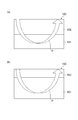
- FIG. 15A and FIG. 15B are diagrams schematically illustrating the internal configuration of the scattering medium 100.
- the scattering medium 100 includes a measurement target region 101 and an intervening tissue 102.
- FIG. 15A shows a case where the intervening tissue 102 is thicker than that in FIG.
- the thickness t of the intervening tissue 102 when the thickness t of the intervening tissue 102 is thin, most of the optical path length of the light P incident on the scattering medium 100 is included in the measurement target region 101. Therefore, a measured value close to the original value can be obtained.
- the thickness t of the intervening tissue 102 when the thickness t of the intervening tissue 102 is thick, the proportion of the portion of the optical path length of the light P incident on the scattering medium 100 that passes through the intervening tissue 102 increases. Resulting in.
- the intervening tissue 102 becomes thicker, the partial optical path length passing through the measurement target region 101 becomes shorter, so that the measured value is calculated smaller than the original value.
- Non-Patent Document 1 described above does not describe what kind of relationship there is between fat thickness and average optical path length. Moreover, in the method described in Non-Patent Document 2, it is necessary to measure the fat thickness of the measurement site in advance for each person to be measured, and there is a problem that the measurement becomes complicated.
- An object of the present invention is to provide a scattering absorber measurement method and apparatus capable of obtaining measurement results excluding the influence of intervening tissues by a simple method.
- a scattering absorber measurement method includes a measurement target region and a measurement target of the scattering absorber including an intervening tissue existing between the measurement target region and the surface.
- a method for non-invasively measuring information related to the amount of a substance to be measured in a region wherein (a) light incident at a predetermined wavelength from one light incident position set on the surface of the scattering medium (B) a light detection step of detecting light of a predetermined wavelength propagated inside the scattering medium at one light detection position set on the surface of the scattering medium and obtaining a light detection signal; A signal processing step for obtaining a time waveform about the light intensity of the detection light based on the light detection signal, (d) an average optical path length of light of a predetermined wavelength inside the scattering medium based on the time waveform, and a measurement object Amount of substance to be measured in the area
- the scattering medium measuring apparatus includes a measurement target region and an amount of a substance to be measured in the measurement target region of the scattering medium including an intervening tissue existing between the measurement target region and the surface.
- a light incident means for injecting light of a predetermined wavelength from one light incident position set on the surface of the scattering medium; and
- scattering Light detection means for detecting light at a predetermined wavelength propagated inside the absorber at one light detection position set on the surface of the scattering medium and generating a light detection signal; and (c) based on the light detection signal.
- a signal processing means for acquiring a time waveform about the light intensity of the detection light; (d) based on the time waveform, an average optical path length of light of a predetermined wavelength inside the scattering medium, and a substance to be measured in the measurement target region Calculation means for calculating information related to quantity Equipped with a.
- the calculation means corrects information related to the amount of the substance to be measured based on the average optical path length so that the amount of the substance to be measured increases as the average optical path length increases.
- the inventors of the present invention have found that there is a significant correlation between the average optical path length and the intervening tissue thickness after intensive studies. Therefore, by correcting the measurement result (information related to the amount of the substance to be measured) based on the average optical path length, the influence of the intervening tissue can be easily removed. That is, according to this scattering absorber measuring method and apparatus, the measurement result excluding the influence of the intervening tissue can be obtained by a simple method.
- the information related to the amount of the substance to be measured refers to information related to the number, concentration, time variation, and other amounts of the substance to be measured.
- information related to the amount of the substance to be measured may be corrected based on the correlation between the average optical path length and the thickness of the intervening tissue acquired in advance.
- the calculation means of the scattering medium measuring apparatus may correct information related to the amount of the substance to be measured based on the correlation between the average optical path length and the thickness of the intervening tissue, which has been acquired in advance. Thereby, information related to the amount of the substance to be measured can be suitably corrected.
- the correlation between the average optical path length and the thickness of the intervening tissue may be a relationship in which the intervening tissue becomes thicker as the average optical path length becomes longer.
- information related to the amount of the substance to be measured may be corrected based on the optical path length per unit thickness of the intervening tissue, which is acquired in advance.
- the calculation means of the scattering medium measuring apparatus may correct the information related to the amount of the substance to be measured based on the optical path length per unit thickness of the intervening tissue that has been acquired in advance.
- the optical path length per unit thickness of the intervening tissue is obtained from the relationship between the amount of change in the substance to be measured when only the substance to be measured is changed and the thickness of the intervening tissue.
- information related to the amount of the substance to be measured may be corrected based on the correlation between the average optical path length and the measurement sensitivity acquired in advance.
- the calculation means of the scattering medium measuring apparatus may correct information related to the amount of the substance to be measured based on the correlation between the average optical path length and the measurement sensitivity that has been acquired in advance.
- the correlation between the average optical path length and the measurement sensitivity is calculated by comparing the average optical path length inside the scattering medium with the optical path length of the portion that passes through the intervening tissue or the measurement target region, and the average. You may obtain
- the calculation means of the scattering medium measuring apparatus calculates the correlation between the average optical path length and the measurement sensitivity, the average optical path length inside the scattering medium, the optical path length of the portion that passes through the intervening tissue or measurement target region, and the average You may obtain
- the optical path length of the portion that passes through the intervening tissue in the average optical path length inside the scattering medium is obtained in advance as the optical path length per unit thickness of the intervening tissue.
- Estimate based on the thickness of the intervening tissue obtained from the correlation between the average optical path length and the thickness of the intervening tissue obtain the measurement sensitivity from the estimated optical path length, and measure the information related to the amount of the substance to be measured You may correct
- the calculation means of the scattering medium measuring apparatus obtains in advance the optical path length of the portion of the average optical path length inside the scattering medium that passes through the intervening tissue, as the optical path length per unit thickness of the intervening tissue.
- the measurement target region may be muscle and the intervening tissue may be fat.
- the measurement result excluding the influence of the intervening tissue can be obtained by a simple method.
- FIG. 1 is a block diagram schematically showing a configuration of an embodiment of a scattering medium measuring apparatus that is preferably used for implementing the scattering medium measuring method according to the present invention.
- FIG. 2 is a block diagram illustrating an example of the internal configuration of the arithmetic processing unit.
- FIG. 3 is a diagram for explaining a method of calculating an average optical path length in the average optical path length calculation unit.
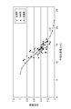
- FIG. 4 is a graph plotting the relationship between the average optical path length actually measured using the scattering medium measuring method and the thickness of the intervening tissue (fat) measured using the ultrasonic device.
- FIG. 1 is a block diagram schematically showing a configuration of an embodiment of a scattering medium measuring apparatus that is preferably used for implementing the scattering medium measuring method according to the present invention.
- FIG. 2 is a block diagram illustrating an example of the internal configuration of the arithmetic processing unit.
- FIG. 3 is a diagram for explaining a method of calculating an average optical path length in the average optical path length
- FIG. 5 is a graph plotting the relationship between the measurement result of the amount of substance to be measured (deoxyhemoglobin amount) per minute and the intervening tissue thickness when the forearm is arterial driven at 250 mmHg. .
- FIG. 6 is a graph plotting the relationship between the measurement result of the amount of substance to be measured (deoxyhemoglobin amount) per minute and the intervening tissue thickness when the thigh is arterial driven at 250 mmHg. is there.
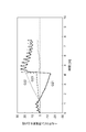
- FIG. 7 is a graph plotting the relationship between the actually measured average optical path length and the measurement sensitivity obtained from Equation (1).
- FIG. 8 is a graph showing the correlation between the average optical path length and the measurement sensitivity.
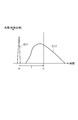
- FIG. 9 is a graph showing a typical example of the TRS measurement result (blood flow change amount).
- FIG. 10 is a chart showing the average optical path length of 14 persons, the intervening tissue thickness estimated from the average optical path length, and the measurement sensitivity estimated from the partial optical path length.
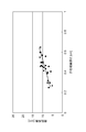
- FIG. 11 is a graph plotting the correlation between the blood flow measurement value before correction by TRS and the blood flow measurement value by plethysmography.
- FIG. 12 is a graph plotting the correlation between the blood flow measurement value by TRS corrected by the measurement sensitivity S and the blood flow measurement value by plethysmography.
- FIG. 13 is a flowchart showing a process flow of the scattering medium measuring method.
- FIG. 14 is a graph showing the correlation between the scattering coefficient and the intervening tissue thickness.
- FIGS. 15A and 15B are diagrams schematically showing the internal configuration of the scattering medium.
- FIG. 1 is a block diagram schematically showing a configuration of an embodiment of a scattering medium measuring apparatus suitably used for carrying out a scattering medium measuring method.
- the scattering medium measuring apparatus 1 calculates information (amount, change amount, concentration, etc.) relating to the amount of the substance to be measured (oxyhemoglobin and deoxyhemoglobin) contained in the tissue of the scattering medium (biological tissue) B. It is a device.
- the scattering medium B includes a measurement target region B1 (for example, muscle) and an intervening tissue B2 (for example, fat) that exists between the measurement target region B1 and the surface Ba of the scattering medium B. Since there is little blood in the intervening tissue B2, most of the substance to be measured exists in the measurement target region B1.
- the scattering medium measuring apparatus 1 calculates information regarding the amount of the substance to be measured present in the measurement target region B1.
- the scattering medium measuring apparatus 1 includes a main body 60 and a display unit 70.
- the main body 60 includes a light incident means 10, a light detection means 20, a signal processing means 30, a calculation means 40, and a control portion 50 that performs these controls.
- the light incident means 10 is a means for entering the pulsed light P having a predetermined wavelength from the light incident position I of the scattering medium B.
- one light incident position I is set on the surface Ba of the scattering medium B.
- the light incident means 10 includes a pulse light source 11 that generates pulsed light P and a light incident light guide 12.
- the input end of the light incident light guide 12 is optically connected to the pulse light source 11.
- the output end of the light incident light guide 12 is disposed at the light incident position I of the scattering medium B.
- the pulse light source 11 various devices such as a light emitting diode, a laser diode, and various pulse laser devices are used.
- the pulsed light P generated in the pulsed light source 11 has a wavelength that has a short pulse width to the extent that the amount of change in the absorption coefficient of the scattering medium B can be measured, and has a high light absorption rate in the light absorption characteristics of the substance to be measured Pulse light having a central wavelength of (for example, near infrared pulse light) is used.
- the light incident light guide 12 for example, an optical fiber is used.
- the light detection means 20 is means for detecting the pulsed light P propagated inside the scattering medium B as detection light.
- one light detection position D is set on the surface Ba of the scattering medium B.
- the light detection means 20 includes a light guide 21 for light detection and a light detector 22 that detects light and converts it into an electrical detection signal.
- the input end of the light detection light guide 21 is disposed at the light detection position D of the scattering medium B.
- the output end of the light detection light guide 21 is optically connected to the light detector 22.
- an optical fiber is used as the light guide 21 for light detection.
- the photodetector 22 various types such as a photomultiplier tube, a photodiode, an avalanche photodiode, and a PIN photodiode are used.
- the photodetector 22 may have spectral sensitivity characteristics that can sufficiently detect the light intensity in the wavelength range of the pulsed light P emitted from the pulsed light source 11. When the detection light is weak, a high sensitivity or high gain photodetector may be used.
- the signal processing means 30 is means for performing predetermined signal processing on the light detection signal provided from the light detection means 20.
- the signal processing means 30 of this embodiment includes a time waveform measurement unit 31.
- the time waveform measurement unit 31 is electrically connected to the light detector 22 and acquires a time waveform regarding the light intensity of the detection light based on the light detection signal from the light detector 22.
- a trigger signal indicating the emission timing of the pulsed light P is provided from the pulse light source 11 to the time waveform measuring unit 31.
- the computing means 40 is a means for computing information related to the amount of the substance to be measured in the measurement target region B1 of the scattering medium B based on the time waveform obtained by the time waveform measuring unit 31.
- the arithmetic means 40 includes an arithmetic processing unit 41.
- the arithmetic processing unit 41 calculates a concentration change amount of the substance to be measured excluding the influence of the intervening tissue B2 by performing a predetermined calculation.
- the arithmetic processing unit 41 is electrically connected to the time waveform measurement unit 31 and receives information related to the time waveform of the detection light from the time waveform measurement unit 31.
- FIG. 2 is a block diagram illustrating an example of the internal configuration of the arithmetic processing unit 41.
- the calculation processing unit 41 of the present embodiment includes an uncorrected change amount calculation unit 411, an average optical path length calculation unit 412, an intervening tissue thickness calculation unit 413, a unit optical path length calculation unit 414, and a partial optical path length.
- a calculation unit 415, a measurement sensitivity calculation unit 416, and a correction calculation unit 417 are included.
- the pre-correction change amount calculation unit 411 obtains the absorption coefficient change amount ⁇ a from the previous measurement time in the scattering medium B based on the time waveform of the detection light provided from the time waveform measurement unit 31.
- the absorption coefficient change amount ⁇ a may be calculated from a change in the light intensity of the detection light, or may be calculated as a difference between a quantitative value ⁇ a obtained by a diffusion equation.
- the amount of change in concentration of the substance to be measured can be derived from ⁇ a calculated by the change amount calculation unit 411 before correction.
- the average optical path length calculation unit 412 calculates the average optical path length L based on the time waveform of the detection light provided from the time waveform measurement unit 31.
- the average optical path length L may be provided to the pre-correction change amount calculation unit 411 for analysis.
- the intervening tissue thickness calculation unit 413 receives information related to the average optical path length L from the average optical path length calculation unit 412, and based on the correlation between the average optical path length L and the thickness of the intervening tissue B2 (dimension A shown in FIG. 1). The thickness of the intervening tissue B2 is estimated.
- the correlation between the average optical path length L and the thickness A of the intervening tissue B2 is stored in advance in storage means such as a nonvolatile memory, and the intervening tissue thickness calculator 413 relates to the thickness A corresponding to the average optical path length L.
- the numerical value is read from the storage means.
- the unit optical path length calculation unit 414 calculates the optical path length LA per unit thickness of the intervening tissue B2.
- information related to the correlation between the thickness A of the intervening tissue B2 and the amount of change ⁇ X before correction when only the concentration of the substance to be measured is changed is stored in advance in storage means such as a nonvolatile memory.
- the thickness A of the intervening tissue B2 may be estimated from the storage means of the intervening tissue thickness calculation unit 413, or may be measured by other devices such as an ultrasonic device.
- the unit optical path length calculator 414 calculates the optical path length LA per unit thickness of the intervening tissue B2 based on these correlations.
- the unit optical path length calculation unit 414 calculates the optical path length per unit thickness of the intervening tissue B2 from the correlation between the thickness A of the intervening tissue B2 and the amount of change ⁇ X before correction when only the concentration of the substance to be measured is changed.
- LA is estimated as follows.
- the numerical value obtained by the following equation (1) can be regarded as the measurement sensitivity (correction coefficient S).
- LM is the optical path length of the portion that passes through the measurement target region B1 out of the average optical path length L that passes through the entire scattering medium B.
- LF is the optical path length of the portion that passes through the intervening tissue B2.
- the partial optical path length LF passing through the intervening tissue B2 is expressed by, for example, the following formula (2).
- A is the thickness of the intervening tissue B2 provided from the intervening tissue thickness calculating unit 413
- LA is the optical path length per unit thickness of the intervening tissue B2.
- the relationship with the change amount ⁇ X before correction is expressed by the following equation (3).
- the following processing is performed under the assumption that there is almost no individual difference in oxygen consumption at the same site in the measurement target region B1.
- the intervening tissue thickness A estimated from this average optical path length L, and only the substance to be measured are changed
- the above equation (3) for a plurality of persons is prepared using the change amount ⁇ X before correction of the substance to be measured.
- the common LA the optical path length per unit thickness of the intervening tissue B2
- ⁇ X B1 the amount of material to be measured in the measurement target region B1 that minimizes the following formula (4) derived from the above formula (3) ) Is calculated by the unit optical path length calculation unit 414.
- Information on the correlation between the thickness A of the intervening tissue B2 and the amount of change ⁇ X before correction when only the concentration of the substance to be measured is changed is stored in the storage means, and the optical path length LA per unit thickness of the intervening tissue B2 is accumulated. If it is determined, it is not necessary to perform another measurement for changing only the concentration of the substance to be measured for each subject.
- the partial optical path length calculation unit 415 calculates the optical path length (partial optical path length LF) of the portion that passes through the intervening tissue B2 out of the average optical path length L that passes through the entire scattering medium B.
- the partial optical path length calculation unit 415 uses the formula (2), for example, the thickness A of the intervening tissue B2 provided from the intervening tissue thickness calculation unit 413 and the unit of the intervening tissue B2 provided from the unit optical path length calculation unit 414.
- the partial optical path length LF is obtained from the optical path length LA per thickness.
- the measurement sensitivity calculation unit 416 calculates the measurement sensitivity (correction coefficient) S estimated by Expression (1) based on the partial optical path length LF.
- the correction calculation unit 417 uses the measurement sensitivity S calculated by the measurement sensitivity calculation unit 416 for the change amount of the substance to be measured (oxyhemoglobin, deoxyhemoglobin, total hemoglobin) calculated by the pre-correction change amount calculation unit 411. to correct.
- the display unit 70 is connected to the main body unit 60.
- the display unit 70 displays the change amount of the measured substance (oxyhemoglobin, deoxyhemoglobin, total hemoglobin) after the thickness A of the intervening tissue B2 and the correction as necessary.
- FIG. 3 is a diagram for explaining a method of calculating the average optical path length L in the average optical path length calculation unit 412.
- the vertical axis indicates the amount of light (logarithmic scale), and the horizontal axis indicates time.
- Graph G11 is the time waveform of the pulsed light intensity incident from the light projecting means 10 to the scattering medium B at time t 0 (the incident wave).
- Graph G12 is the time waveform of the detected light intensity corresponding to the incident pulsed light at time t 0 (detection waveform).
- the time that the light propagated inside the scattering medium B reaches the light detection position D is not uniform depending on the propagation state, and is attenuated by scattering and absorption in the scattering medium B. Therefore, as shown in the graph G12 of FIG. 3, the detected waveform is a certain distribution curve.
- FIG. 4 is a graph plotting the relationship between the average optical path length L actually measured using such a method and the thickness A of the intervening tissue (fat) B2 measured using the ultrasonic device. is there.
- the vertical axis represents the intervening tissue thickness A (cm)
- the horizontal axis represents the average optical path length L (cm).
- the average optical path length L becomes long, so that the intervening tissue thickness A is thick.
- the correlation between the intervening tissue thickness A and the average optical path length L is suitably represented by, for example, the approximate straight line L1 shown in FIG.
- the approximate straight line L1 is represented by the following equation (5), and its R 2 value was 0.7391. Note that this relational expression is not limited to Expression (5), and the approximate expression may change as the number of data increases.
- the thickness A of the intervening tissue B2 can be estimated from the average optical path length L.
- the interstitial tissue thickness calculator 413 estimates the thickness A of the intervening tissue B2 using the average optical path length L obtained by the average optical path length calculator 412 and the above equation (5).
- DPF DifferentifPathlength Factor
- FIG. 5 and 6 the vertical axis represents the amount of change in the amount of deoxyhemoglobin, and the horizontal axis represents the interstitial tissue thickness A.
- the measurement sensitivity S is obtained by the measurement sensitivity calculation unit 416, if the partial optical path length LM in the measurement target region B1 in the average optical path length L can be estimated, the measurement sensitivity S is obtained by Expression (1). Can do. However, although the partial optical path length LM can be estimated using simulation, it is necessary to assume the optical coefficient and thickness of each component (measurement target region B1, intervening tissue B2, etc.), which is not realistic. .
- the unit optical path length calculation unit 414 performs measurement data by light incidence at one place and light detection at one place
- the optical path length LA per unit thickness of the intervening tissue B2 can be obtained from the relationship between the average optical path length L and the amount of change in the substance to be measured.
- the measurement sensitivity calculation unit 416 uses the optical path length LA, the average optical path length L, and the intervening tissue thickness A per unit thickness of the intervening tissue B2 obtained, in the measurement sensitivity calculation unit 416, from Equations (1) and (2), The partial optical path lengths LM and LF can be obtained, and further the measurement sensitivity S can be obtained.
- the measurement target region B1 is muscle and the intervening tissue B2 is fat
- the blood volume and oxygen consumption of fat are extremely small compared to the muscle. It is thought that it is not.
- the oxygen consumption is large in the measurement target region B1. Therefore, the relationship between the deoxyhemoglobin change amount ⁇ Hbm in the measurement target region B1 that is increased by the blood pumping and the deoxyhemoglobin change amount ⁇ Hb obtained by the measurement is expressed by the following equation (6).
- the measurement sensitivity calculation unit 416 uses the equations (1) and (2) to The measurement sensitivity S can be obtained for each subject.
- the relational expression may be used. It is not necessary to give a load such as driving.
- the LF and ⁇ Hbm of the forearm and thigh were obtained from the measurement data shown in FIGS. ⁇ Hbm was estimated to be 23.11 ⁇ M for the forearm and 13.47 ⁇ M for the thigh.
- the partial optical path length LF for the intervening tissue thickness (fat thickness) of 1 cm was estimated to be 9.14 cm for the forearm and 9.57 cm for the thigh.
- FIG. 7 is a graph plotting the relationship between the actually measured average optical path length L and the measurement sensitivity S obtained from the above equation (1).
- the vertical axis represents the measurement sensitivity S
- the horizontal axis represents the intervening tissue thickness A.
- the square plot indicates the forearm
- the triangle plot indicates the thigh
- the asterisk-shaped plot indicates the theoretical value.
- the mathematical formula of the theoretical value is as follows.
- the measurement sensitivity S decreases as the intervening tissue thickness A increases. Further, by replacing the horizontal axis of FIG. 7 with the average optical path length L from the intervening tissue thickness A using the above equation (5), the average optical path length L can be calculated without measuring the intervening tissue thickness A.
- the measurement sensitivity S can also be derived. Note that the measurement sensitivity calculation unit 416 shown in FIG. 2 calculates the measurement sensitivity S applied during the actual measurement from the relational expression between the measurement sensitivity S and the intervening tissue thickness A.
- the correction calculation unit 417 divides the measurement value (for example, deoxyhemoglobin change amount ⁇ Hb) related to the amount of the substance to be measured by the measurement sensitivity S, thereby removing the measurement target region B1 from the influence of the intervening tissue B2. (For example, deoxyhemoglobin change amount ⁇ Hbm of the measurement target region B1) can be estimated.
- the measurement value for example, deoxyhemoglobin change amount ⁇ Hb
- the partial optical path length LA per unit length (1 cm) in the intervening tissue B2 was, for example, an average of about 9.4 cm. Therefore, by measuring the average optical path length L, estimating the intervening tissue thickness A from the average optical path length L, and applying these to the above formula (2) together with the numerical value of the estimated partial optical path length LA, the intervening tissue B2 The partial optical path length LF can be calculated. Then, using this partial optical path length LF, the contribution rate inside the measurement target region B1 can be estimated from the above equation (1), and the measurement sensitivity S can be obtained.
- FIG. 8 shows the correlation between the average optical path length L and the measurement sensitivity S, and it can be seen that the measurement sensitivity S decreases as the average optical path length L increases. That is, if the average optical path length L at rest is measured, the measurement sensitivity S can be derived, and therefore there is no need to measure the intervening tissue thickness A using a method such as ultrasonic measurement.
- FIG. 8 also shows a theoretical curve L2 in which the measurement sensitivity S is 1 when the intervening tissue thickness A is zero. The function of this theoretical curve L2 is shown in the following equation (9).
- the relational expression used for estimating the measurement sensitivity S is not limited to the theoretical curve L2, and an optimal approximate expression may be used.
- TRS time-resolved spectroscopy system
- the interstitial tissue (fat) thickness A and measurement sensitivity S are estimated using the above-described method, and the TRS measurement value (blood flow value) is calculated using this measurement sensitivity S. ) was corrected, and the corrected value was compared with the measured value by plethysmography.
- FIG. 9 is a graph showing a typical example of the TRS measurement result (blood flow change amount) when this protocol is actually performed.
- the vertical axis represents the amount of change ( ⁇ M) in hemoglobin concentration
- the horizontal axis represents time (minutes).
- Graph G21 indicates the amount of oxyhemoglobin (HbO 2 )
- graph G22 indicates the amount of deoxyhemoglobin (Hb)
- graph G23 indicates the amount of total hemoglobin (tHb).
- FIG. 10 is a chart showing the average optical path length L of 14 persons, the interstitial tissue thickness A estimated from the average optical path length L, and the measurement sensitivity S estimated from the partial optical path length LF.
- the blood flow rate measurement value after correction was obtained by dividing the blood flow rate measurement value by TRS before correction with the measurement sensitivity S shown in FIG.
- FIG. 11 and FIG. 12 are graphs plotting the correlation between the blood flow measurement value by TRS and the blood flow measurement value by plethysmography.
- FIG. 11 shows these correlations before correction
- FIG. 12 shows these correlations when corrected by the measurement sensitivity S. 11 and 12
- the vertical axis represents the blood flow measurement value by TRS
- the horizontal axis represents the blood flow measurement value by plethysmography.
- the unit of blood flow is converted to (ml / min / 100 g) according to the plethysmography.
- measurement of blood flow is taken as an example.
- the measurement in the resting state is first performed, the interstitial tissue thickness A and the measurement sensitivity S are calculated from the average optical path length L, and the amount of blood change when exercise continues It is good to display the value which correct
- the measurement subject can confirm the amount of blood change in the muscle (excluding the influence of fat) in real time. The subject can also know the fat thickness.
- FIG. 13 is a flowchart showing a processing flow of the scattering medium measuring method described above. That is, in the scattering medium measuring method of this embodiment, as shown in FIG. 1, first, pulsed light P having a predetermined wavelength is incident from one light incident position I set on the surface Ba of the scattering medium B. (Light incident step S1). Next, the pulsed light P propagated inside the scattering medium B is detected at one light detection position D set on the surface Ba of the scattering medium B to obtain a light detection signal (light detection step S2).
- a time waveform about the light intensity of the detection light is acquired based on the light detection signal (signal processing step S3).
- the average optical path length L inside the scattering medium B and the information (change amount etc.) related to the amount of the substance to be measured in the measurement target region B1 are calculated (calculation step S4).
- information related to the amount of the substance to be measured is corrected based on the average optical path length L so that the amount of the substance to be measured increases as the average optical path length L increases. For example, since the interstitial tissue thickness A increases as the average optical path length L increases (see FIG. 4), information related to the amount of the substance to be measured is corrected based on such correlation acquired in advance. Good.
- the measurement sensitivity S decreases as the average optical path length L increases (see FIG. 8)
- information related to the amount of the substance to be measured is corrected based on such a correlation acquired in advance. Also good. Or you may correct
- the optical path length LA per unit thickness of the intervening tissue B2 is obtained from the relationship between the amount of change in the substance to be measured when only the substance to be measured is changed and the thickness of the intervening tissue B2.
- the correlation between the average optical path length L and the measurement sensitivity S is the optical path length (partial optical path length LM or partial optical path length LM or part of the average optical path length L inside the scattering medium B that passes through the intervening tissue B2 or the measurement target region B1. LF) and the average optical path length L.
- the partial optical path length LF of the intervening tissue B2 is calculated by using the optical path length LA per unit thickness of the intervening tissue B2 and the previously acquired average optical path length L and Based on the intervening tissue thickness A obtained from the correlation of the intervening tissue thickness A, the measurement sensitivity S is obtained from the estimated partial optical path length LF, and information related to the amount of the substance to be measured is obtained. You may correct using.
- the scattering absorber measurement method described above can be obtained by the scattering absorber measurement method described above. That is, according to this method, since the intervening tissue thickness A can be estimated from the average optical path length L, the substance to be measured in the measurement target region B1 can be obtained without actually measuring the intervening tissue thickness A using an ultrasonic device or the like. It is possible to accurately obtain information on the quantity of Therefore, it becomes possible to compare information on the amount of the substance to be measured regardless of the intervening tissue thickness A which varies depending on the person to be measured and the measurement site.
- the scattering medium measuring method and apparatus according to the present invention are not limited to the above-described embodiments, and various other modifications are possible.
- the above embodiment can also be applied to other methods that can measure the average optical path length, for example, the phase difference method. Even if the average optical path length cannot be measured as in the CW method, if the average optical path length L is measured in advance by time-resolved spectroscopy or the like, the measurement result by such a technique is also corrected. It can be performed.
- the case where the measurement value is corrected in real time has been described.
- the correction may be performed after the measurement is completed.
- the correlation between the intervening tissue thickness and the average optical path length shown in the above embodiment is merely an example.
- the mathematical formula used for correction can be applied to various correction relational expressions.
- the average optical path length measured at the time of rest is used in the said embodiment, it is not restricted at the time of rest, What is necessary is just to have measurement conditions.
- as a method of changing only the substance to be measured in order to measure the amount of change before correction when only the concentration of the substance to be measured is used which is used in the unit optical path length calculation unit 414, blood excision is used. Used.
- the method of changing only the substance to be measured is not limited to this, and it is sufficient if the above conditions are satisfied.
- hemoglobin oxygen-globin, deoxyhemoglobin, total hemoglobin
- hemoglobin is exemplified as the substance to be measured, but other substances may be used as long as they absorb light of a predetermined wavelength.
- correction is performed by dividing the already calculated blood change amount by the measurement sensitivity.
- the absorption coefficient change amount before hemoglobin conversion may be corrected.
- the corrected hemoglobin can be handled.
- the correction in the above embodiment is for the absorption change amount, but may be handled as a quantitative value by adding a relative change amount to the quantitative value obtained from the diffusion equation.
- SO 2 oxygen saturation
- muscle is exemplified as the measurement target region and fat is exemplified as the intervening tissue.
- the measurement target region and the intervening tissue are not limited to these.
- the above-described embodiment can be applied to various multilayer structures such as a brain tissue as a measurement target region and a skull as an intervening tissue.
- the relationship between the average optical path length and the intervening tissue thickness is used.
- the measurement value is corrected using the relationship between the scattering coefficient and the intervening tissue thickness as shown in FIG. good.
- the scattering coefficient increases as the intervening tissue thickness increases. Based on this correlation (or based on the correlation in which the intervening tissue thickness is replaced with the average optical path length), the measurement is performed. The value can be corrected appropriately.
- the thickness of the intervening tissue can be estimated from the average optical path length. Therefore, in addition to correcting the information regarding the amount of the measurement target substance in the measurement target region, for example, instead of the conventional method (such as an ultrasonic device) for measuring the thickness of the intervening tissue, the thickness of the intervening tissue can also be measured. .
- the present invention can be used as a scattering absorber measurement method and apparatus capable of obtaining measurement results excluding the influence of intervening tissues by a simple method.
- SYMBOLS 1 DESCRIPTION OF SYMBOLS 1 ... Scattering absorber measuring apparatus, 10 ... Light incident means, 11 ... Pulse light source, 12 ... Light guide for light incidence, 20 ... Light detection means, 21 ... Light guide for light detection, 22 ... Light detector, 30 ... Signal Processing means 31 ... Time waveform measuring section 40 ... Calculating means 41 ... Calculation processing section 50 ... Control section 60 ... Main body section 70 ... Display device 411 ... Change amount calculator before correction 412 ... Average optical path length Calculation unit, 413 ... Intervening tissue thickness calculation unit, 414 ... Unit optical path length calculation unit, 415 ... Partial optical path length calculation unit, 416 ... Measurement sensitivity calculation unit, 417 ... Correction calculation unit, B ... Scattering absorber, B1 ... Measurement object Area, B2 ... intervening tissue, Ba ... surface, D ... light detection position, P ... pulse light, I ... light incident position.
Abstract
Light (P) of a given wavelength is incident onto one light incident position (I) located on the surface (Ba) of a scattering-absorption body (B) and the light (P) propagating through the inside of the scattering-absorption body (B) is detected at one light detection position (D) located on the surface (Ba) of a scattering-absorption body (B) to produce a light detection signal. A time waveform in association with the light intensity of the detected light is obtained on the basis of the light detection signal, and the average length of the light path (L) of the light (P) within the inside of the scattering-absorption body (B) and the information associated with the amount of substance to be measured in a measuring region (B1) are calculated on the basis of the time waveform. On this occasion, the information associated with the amount of substance to be measured is corrected based on the average length of the light path (L) such that the longer the average length of the light path (L), the greater the amount of substance to be measured becomes. According to this method, measuring results free from the effects of interposing tissues can be obtained using a simple method.
Description
本発明は、例えば血液中のヘモグロビンといった、散乱吸収体内物質の量(濃度)に関する情報を測定する方法及び装置に関する。
The present invention relates to a method and an apparatus for measuring information related to the amount (concentration) of a substance in a scattering medium such as hemoglobin in blood.
特許文献1には、散乱吸収体の内部を非侵襲的に測定する方法が記載されている。この測定方法では、測定対象領域と非測定対象領域とを含む散乱吸収体に対し、光入射手段によって光入射位置から入射したパルス光が、散乱しながらそれぞれの光路で光検出位置に達し、光検出手段にて検出される。なお、光入射位置及び光検出位置のうち少なくとも一方が複数である。この検出光の時間波形を用い、非測定対象領域を伝搬する部分光路長が光路によらず一定であるとして、測定対象領域のみの吸収係数変化量を算出している。
Patent Document 1 describes a method of non-invasively measuring the inside of a scattering medium. In this measurement method, the pulsed light incident from the light incident position by the light incident means reaches the light detection position in each optical path while being scattered with respect to the scattering medium including the measurement target region and the non-measurement target region. It is detected by the detection means. Note that at least one of the light incident position and the light detection position is plural. Using the time waveform of the detection light, the amount of change in the absorption coefficient of only the measurement target region is calculated on the assumption that the partial optical path length propagating in the non-measurement target region is constant regardless of the optical path.
また、非特許文献1には、近赤外線分光法(NIRS:near-infrared spectroscopy)による計測において、筋肉や脂肪といった組織構成、血液量、及び筋肉形状によって、体内を伝搬する光の平均光路長が変化することが記載されている。
Non-Patent Document 1 discloses the average optical path length of light propagating through the body depending on the tissue configuration such as muscle and fat, blood volume, and muscle shape in near-infrared spectroscopy (NIRS) measurement. It is described to change.
また、非特許文献2には、脂肪厚さを別の方法によって予め測定しておき、近赤外線分光法によるヘモグロビン量の測定結果を、その脂肪厚さに応じて補正することが記載されている。
Non-Patent Document 2 describes that fat thickness is measured in advance by another method, and the measurement result of the amount of hemoglobin by near infrared spectroscopy is corrected according to the fat thickness. .
光を用いた散乱吸収体の非侵襲測定において、散乱吸収体が、測定対象領域の他に、該測定対象領域と表皮との間に介在する非測定対象領域(介在組織)を含む場合がある。例えば、近赤外分光法を用いた筋肉の血行動態評価を行う場合、筋肉を覆っている脂肪は、筋肉に比べ血液量が顕著に少ないため、筋肉は測定対象領域として扱われ、脂肪は非測定対象である介在組織として扱われる。
In non-invasive measurement of a scattering medium using light, the scattering medium may include a non-measurement target region (intervening tissue) interposed between the measurement target region and the epidermis in addition to the measurement target region. . For example, when performing hemodynamic evaluation of muscles using near infrared spectroscopy, the fat covering the muscles is significantly less blood than the muscles, so the muscles are treated as the measurement area and the fat is non- Treated as an intervening tissue to be measured.
しかしながら、散乱吸収体を非侵襲的に測定するためには、測定対象領域に対し、介在組織を介して光を入射・検出する必要がある。このため、介在組織の厚さによって測定結果にばらつきが生じ、測定精度を低下させる一因となる。ここで、図15(a)及び図15(b)は、散乱吸収体100の内部構成を模式的に示す図である。これらの図において、散乱吸収体100は、測定対象領域101及び介在組織102からなる。図15(a)は、図15(b)と比べて介在組織102が厚い場合を示している。
However, in order to measure the scattering medium in a non-invasive manner, it is necessary to make light incident and detected on the measurement target region via the intervening tissue. For this reason, the measurement results vary depending on the thickness of the intervening tissue, which contributes to a decrease in measurement accuracy. Here, FIG. 15A and FIG. 15B are diagrams schematically illustrating the internal configuration of the scattering medium 100. In these drawings, the scattering medium 100 includes a measurement target region 101 and an intervening tissue 102. FIG. 15A shows a case where the intervening tissue 102 is thicker than that in FIG.
図15(b)に示されるように、介在組織102の厚さtが薄い場合、散乱吸収体100に入射された光Pの光路長のうち大部分は、測定対象領域101に含まれる。従って、本来の値に近い測定値が得られる。しかし、図15(a)に示されるように、介在組織102の厚さtが厚い場合、散乱吸収体100に入射された光Pの光路長のうち介在組織102を通過する部分の割合が増加してしまう。このように、介在組織102が厚くなるほど、測定対象領域101を通過する部分光路長が短くなるので、本来の値に対して測定値が小さく算出されてしまう。
As shown in FIG. 15B, when the thickness t of the intervening tissue 102 is thin, most of the optical path length of the light P incident on the scattering medium 100 is included in the measurement target region 101. Therefore, a measured value close to the original value can be obtained. However, as shown in FIG. 15A, when the thickness t of the intervening tissue 102 is thick, the proportion of the portion of the optical path length of the light P incident on the scattering medium 100 that passes through the intervening tissue 102 increases. Resulting in. Thus, as the intervening tissue 102 becomes thicker, the partial optical path length passing through the measurement target region 101 becomes shorter, so that the measured value is calculated smaller than the original value.
なお、上述した非特許文献1には、脂肪厚さと平均光路長との間にどのような関係があるのかに関しては記載されていない。また、非特許文献2に記載された方法では、測定部位の脂肪厚さを予め被測定者毎に計測しておく必要があり、測定が煩雑になるという問題がある。
It should be noted that Non-Patent Document 1 described above does not describe what kind of relationship there is between fat thickness and average optical path length. Moreover, in the method described in Non-Patent Document 2, it is necessary to measure the fat thickness of the measurement site in advance for each person to be measured, and there is a problem that the measurement becomes complicated.
本発明は、介在組織の影響を除いた測定結果を簡易な方法によって得ることができる、散乱吸収体測定方法及び装置を提供することを目的とする。
An object of the present invention is to provide a scattering absorber measurement method and apparatus capable of obtaining measurement results excluding the influence of intervening tissues by a simple method.
上述した課題を解決するために、本発明の一実施形態に係る散乱吸収体測定方法は、測定対象領域、及び測定対象領域と表面との間に存在する介在組織を含む散乱吸収体の測定対象領域における被測定物質の量に関連する情報を非侵襲的に測定する方法であって、(a)散乱吸収体の表面に設定された一つの光入射位置から所定波長の光を入射する光入射ステップと、(b)散乱吸収体内部を伝搬した所定波長の光を、散乱吸収体の表面に設定された一つの光検出位置で検出して光検出信号を得る光検出ステップと、(c)光検出信号に基づいて、検出光の光強度についての時間波形を取得する信号処理ステップと、(d)時間波形に基づいて、散乱吸収体内部における所定波長の光の平均光路長と、測定対象領域における被測定物質の量に関連する情報とを演算する演算ステップとを備え、演算ステップにおいて、平均光路長が長いほど被測定物質の量が多くなるように、平均光路長に基づいて被測定物質の量に関連する情報を補正する。また、本発明の一実施形態に係る散乱吸収体測定装置は、測定対象領域、及び測定対象領域と表面との間に存在する介在組織を含む散乱吸収体の測定対象領域における被測定物質の量に関連する情報を非侵襲的に測定する装置であって、(a)散乱吸収体の表面に設定された一つの光入射位置から所定波長の光を入射する光入射手段と、(b)散乱吸収体内部を伝搬した所定波長の光を、散乱吸収体の表面に設定された一つの光検出位置で検出して光検出信号を生成する光検出手段と、(c)光検出信号に基づいて、検出光の光強度についての時間波形を取得する信号処理手段と、(d)時間波形に基づいて、散乱吸収体内部における所定波長の光の平均光路長と、測定対象領域における被測定物質の量に関連する情報とを演算する演算手段とを備える。演算手段は、平均光路長が長いほど被測定物質の量が多くなるように、平均光路長に基づいて被測定物質の量に関連する情報を補正する。
In order to solve the above-described problem, a scattering absorber measurement method according to an embodiment of the present invention includes a measurement target region and a measurement target of the scattering absorber including an intervening tissue existing between the measurement target region and the surface. A method for non-invasively measuring information related to the amount of a substance to be measured in a region, wherein (a) light incident at a predetermined wavelength from one light incident position set on the surface of the scattering medium (B) a light detection step of detecting light of a predetermined wavelength propagated inside the scattering medium at one light detection position set on the surface of the scattering medium and obtaining a light detection signal; A signal processing step for obtaining a time waveform about the light intensity of the detection light based on the light detection signal, (d) an average optical path length of light of a predetermined wavelength inside the scattering medium based on the time waveform, and a measurement object Amount of substance to be measured in the area A calculation step for calculating related information, and in the calculation step, information related to the amount of the substance to be measured is calculated based on the average optical path length so that the amount of the substance to be measured increases as the average optical path length increases. to correct. Moreover, the scattering medium measuring apparatus according to one embodiment of the present invention includes a measurement target region and an amount of a substance to be measured in the measurement target region of the scattering medium including an intervening tissue existing between the measurement target region and the surface. (A) a light incident means for injecting light of a predetermined wavelength from one light incident position set on the surface of the scattering medium; and (b) scattering. Light detection means for detecting light at a predetermined wavelength propagated inside the absorber at one light detection position set on the surface of the scattering medium and generating a light detection signal; and (c) based on the light detection signal. A signal processing means for acquiring a time waveform about the light intensity of the detection light; (d) based on the time waveform, an average optical path length of light of a predetermined wavelength inside the scattering medium, and a substance to be measured in the measurement target region Calculation means for calculating information related to quantity Equipped with a. The calculation means corrects information related to the amount of the substance to be measured based on the average optical path length so that the amount of the substance to be measured increases as the average optical path length increases.
本発明者らは、鋭意研究の末、平均光路長と介在組織厚さとの間に顕著な相関があることを見出した。従って、平均光路長に基づいて測定結果(被測定物質の量に関連する情報)を補正することにより、介在組織による影響を容易に取り除くことができる。すなわち、この散乱吸収体測定方法及び装置によれば、介在組織の影響を除いた測定結果を簡易な方法によって得ることができる。なお、被測定物質の量に関連する情報とは、被測定物質の数、濃度、時間変化量、その他の量に関する情報をいう。
The inventors of the present invention have found that there is a significant correlation between the average optical path length and the intervening tissue thickness after intensive studies. Therefore, by correcting the measurement result (information related to the amount of the substance to be measured) based on the average optical path length, the influence of the intervening tissue can be easily removed. That is, according to this scattering absorber measuring method and apparatus, the measurement result excluding the influence of the intervening tissue can be obtained by a simple method. Note that the information related to the amount of the substance to be measured refers to information related to the number, concentration, time variation, and other amounts of the substance to be measured.
また、散乱吸収体測定方法では、演算ステップにおいて、予め取得しておいた、平均光路長と介在組織の厚さとの相関に基づいて、被測定物質の量に関連する情報を補正してもよい。また、散乱吸収体測定装置の演算手段は、予め取得しておいた、平均光路長と介在組織の厚さとの相関に基づいて、被測定物質の量に関連する情報を補正してもよい。これによって、被測定物質の量に関連する情報を好適に補正することができる。この場合、平均光路長と介在組織の厚さとの相関は、平均光路長が長くなるほど介在組織が厚くなる関係であってもよい。
In the scattering medium measuring method, in the calculation step, information related to the amount of the substance to be measured may be corrected based on the correlation between the average optical path length and the thickness of the intervening tissue acquired in advance. . Further, the calculation means of the scattering medium measuring apparatus may correct information related to the amount of the substance to be measured based on the correlation between the average optical path length and the thickness of the intervening tissue, which has been acquired in advance. Thereby, information related to the amount of the substance to be measured can be suitably corrected. In this case, the correlation between the average optical path length and the thickness of the intervening tissue may be a relationship in which the intervening tissue becomes thicker as the average optical path length becomes longer.
また、散乱吸収体測定方法では、演算ステップにおいて、予め取得しておいた、介在組織の単位厚当たりの光路長に基づいて、被測定物質の量に関連する情報を補正してもよい。同様に、散乱吸収体測定装置の演算手段は、予め取得しておいた、介在組織の単位厚当たりの光路長に基づいて、被測定物質の量に関連する情報を補正してもよい。介在組織の単位厚当たりの光路長は、被測定物質のみ変化させたときの被測定物質変化量と介在組織の厚さとの関係より得られる。或いは、散乱吸収体測定方法では、演算ステップにおいて、予め取得しておいた、平均光路長と測定感度との相関に基づいて、被測定物質の量に関連する情報を補正してもよい。同様に、散乱吸収体測定装置の演算手段は、予め取得しておいた、平均光路長と測定感度との相関に基づいて、被測定物質の量に関連する情報を補正してもよい。また、散乱吸収体測定方法では、演算ステップにおいて、平均光路長と測定感度との相関を、散乱吸収体内部における平均光路長のうち介在組織又は測定対象領域を通過する部分の光路長と、平均光路長とから求めてもよい。同様に、散乱吸収体測定装置の演算手段は、平均光路長と測定感度との相関を、散乱吸収体内部における平均光路長のうち介在組織又は測定対象領域を通過する部分の光路長と、平均光路長とから求めてもよい。これらのうち何れかによって、被測定物質の量に関連する情報を好適に補正することができる。
In the scattering medium measuring method, in the calculation step, information related to the amount of the substance to be measured may be corrected based on the optical path length per unit thickness of the intervening tissue, which is acquired in advance. Similarly, the calculation means of the scattering medium measuring apparatus may correct the information related to the amount of the substance to be measured based on the optical path length per unit thickness of the intervening tissue that has been acquired in advance. The optical path length per unit thickness of the intervening tissue is obtained from the relationship between the amount of change in the substance to be measured when only the substance to be measured is changed and the thickness of the intervening tissue. Alternatively, in the scattering medium measuring method, in the calculation step, information related to the amount of the substance to be measured may be corrected based on the correlation between the average optical path length and the measurement sensitivity acquired in advance. Similarly, the calculation means of the scattering medium measuring apparatus may correct information related to the amount of the substance to be measured based on the correlation between the average optical path length and the measurement sensitivity that has been acquired in advance. Further, in the scattering medium measurement method, in the calculation step, the correlation between the average optical path length and the measurement sensitivity is calculated by comparing the average optical path length inside the scattering medium with the optical path length of the portion that passes through the intervening tissue or the measurement target region, and the average. You may obtain | require from optical path length. Similarly, the calculation means of the scattering medium measuring apparatus calculates the correlation between the average optical path length and the measurement sensitivity, the average optical path length inside the scattering medium, the optical path length of the portion that passes through the intervening tissue or measurement target region, and the average You may obtain | require from optical path length. Any of these can suitably correct information relating to the amount of the substance to be measured.
また、散乱吸収体測定方法では、演算ステップにおいて、散乱吸収体内部における平均光路長のうち介在組織を通過する部分の光路長を、介在組織の単位厚さ当たりの光路長と、予め取得しておいた平均光路長と介在組織の厚さとの相関から得られる介在組織の厚さとに基づいて推定し、推定した該光路長から測定感度を求め、被測定物質の量に関連する情報を該測定感度を用いて補正してもよい。同様に、散乱吸収体測定装置の演算手段は、散乱吸収体内部における平均光路長のうち介在組織を通過する部分の光路長を、介在組織の単位厚さ当たりの光路長と、予め取得しておいた平均光路長と介在組織の厚さとの相関から得られる介在組織の厚さとに基づいて推定し、推定した該光路長から測定感度を求め、被測定物質の量に関連する情報を該測定感度を用いて補正してもよい。
In the scattering medium measuring method, in the calculation step, the optical path length of the portion that passes through the intervening tissue in the average optical path length inside the scattering medium is obtained in advance as the optical path length per unit thickness of the intervening tissue. Estimate based on the thickness of the intervening tissue obtained from the correlation between the average optical path length and the thickness of the intervening tissue, obtain the measurement sensitivity from the estimated optical path length, and measure the information related to the amount of the substance to be measured You may correct | amend using a sensitivity. Similarly, the calculation means of the scattering medium measuring apparatus obtains in advance the optical path length of the portion of the average optical path length inside the scattering medium that passes through the intervening tissue, as the optical path length per unit thickness of the intervening tissue. Estimate based on the thickness of the intervening tissue obtained from the correlation between the average optical path length and the thickness of the intervening tissue, obtain the measurement sensitivity from the estimated optical path length, and measure the information related to the amount of the substance to be measured You may correct | amend using a sensitivity.
また、散乱吸収体測定方法及び散乱吸収体測定装置では、測定対象領域が筋肉であり、介在組織が脂肪であってもよい。
In the scattering medium measuring method and the scattering medium measuring apparatus, the measurement target region may be muscle and the intervening tissue may be fat.
本発明による散乱吸収体測定方法及び装置によれば、介在組織の影響を除いた測定結果を簡易な方法によって得ることができる。
According to the scattering medium measuring method and apparatus of the present invention, the measurement result excluding the influence of the intervening tissue can be obtained by a simple method.
以下、添付図面を参照しながら散乱吸収体測定方法及び装置の実施の形態を詳細に説明する。なお、図面の説明において同一の要素には同一の符号を付し、重複する説明を省略する。
Hereinafter, embodiments of the scattering absorber measuring method and apparatus will be described in detail with reference to the accompanying drawings. In the description of the drawings, the same elements are denoted by the same reference numerals, and redundant description is omitted.
図1は、散乱吸収体測定方法の実施に好適に用いられる、散乱吸収体測定装置の一実施形態の構成を概略的に示すブロック図である。この散乱吸収体測定装置1は、散乱吸収体(生体組織)Bの組織中に含まれる被測定物質(オキシヘモグロビン及びデオキシヘモグロビン)の量に関する情報(量、変化量、濃度など)を算出するための装置である。なお、散乱吸収体Bは、測定対象領域B1(例えば筋肉)と、該測定対象領域B1と散乱吸収体Bの表面Baとの間に存在する介在組織B2(例えば脂肪)とを含む。介在組織B2には血液が少ないので、被測定物質の殆どは測定対象領域B1に存在する。散乱吸収体測定装置1は、測定対象領域B1に存在する被測定物質の量に関する情報を算出する。
FIG. 1 is a block diagram schematically showing a configuration of an embodiment of a scattering medium measuring apparatus suitably used for carrying out a scattering medium measuring method. The scattering medium measuring apparatus 1 calculates information (amount, change amount, concentration, etc.) relating to the amount of the substance to be measured (oxyhemoglobin and deoxyhemoglobin) contained in the tissue of the scattering medium (biological tissue) B. It is a device. The scattering medium B includes a measurement target region B1 (for example, muscle) and an intervening tissue B2 (for example, fat) that exists between the measurement target region B1 and the surface Ba of the scattering medium B. Since there is little blood in the intervening tissue B2, most of the substance to be measured exists in the measurement target region B1. The scattering medium measuring apparatus 1 calculates information regarding the amount of the substance to be measured present in the measurement target region B1.
図1に示される散乱吸収体測定装置1は、本体部60及び表示部70を備えている。本体部60は、光入射手段10と、光検出手段20と、信号処理手段30と、演算手段40と、これらの制御を行う制御部分50とを備えている。
1 includes a main body 60 and a display unit 70. The scattering medium measuring apparatus 1 shown in FIG. The main body 60 includes a light incident means 10, a light detection means 20, a signal processing means 30, a calculation means 40, and a control portion 50 that performs these controls.
光入射手段10は、散乱吸収体Bの光入射位置Iから所定波長のパルス光Pを入射する手段である。本実施形態では、散乱吸収体Bの表面Ba上に一箇所の光入射位置Iが設定されている。光入射手段10は、パルス光Pを発生させるパルス光源11と、光入射用光ガイド12とを含む。光入射用光ガイド12の入力端はパルス光源11に光学的に接続されている。光入射用光ガイド12の出力端は散乱吸収体Bの光入射位置Iに配置されている。
The light incident means 10 is a means for entering the pulsed light P having a predetermined wavelength from the light incident position I of the scattering medium B. In the present embodiment, one light incident position I is set on the surface Ba of the scattering medium B. The light incident means 10 includes a pulse light source 11 that generates pulsed light P and a light incident light guide 12. The input end of the light incident light guide 12 is optically connected to the pulse light source 11. The output end of the light incident light guide 12 is disposed at the light incident position I of the scattering medium B.
パルス光源11としては、発光ダイオード、レーザーダイオード、各種パルスレーザ装置など、様々なものが用いられる。パルス光源11において発生するパルス光Pとしては、散乱吸収体Bの吸収係数の変化量を測定できる程度にパルスの時間幅が短く、且つ、被測定物質の光吸収特性において光吸収率が高い波長を中心波長とするパルス光(例えば近赤外パルス光)が用いられる。光入射用光ガイド12としては、例えば光ファイバが用いられる。
As the pulse light source 11, various devices such as a light emitting diode, a laser diode, and various pulse laser devices are used. The pulsed light P generated in the pulsed light source 11 has a wavelength that has a short pulse width to the extent that the amount of change in the absorption coefficient of the scattering medium B can be measured, and has a high light absorption rate in the light absorption characteristics of the substance to be measured Pulse light having a central wavelength of (for example, near infrared pulse light) is used. As the light incident light guide 12, for example, an optical fiber is used.
光検出手段20は、散乱吸収体Bの内部を伝搬したパルス光Pを検出光として検出する手段である。本実施形態では、散乱吸収体Bの表面Ba上に一箇所の光検出位置Dが設定されている。光検出手段20は、光検出用光ガイド21と、光を検出して電気的な検出信号に変換する光検出器22とを含む。光検出用光ガイド21の入力端は散乱吸収体Bの光検出位置Dに配置されている。光検出用光ガイド21の出力端は光検出器22に光学的に接続されている。
The light detection means 20 is means for detecting the pulsed light P propagated inside the scattering medium B as detection light. In the present embodiment, one light detection position D is set on the surface Ba of the scattering medium B. The light detection means 20 includes a light guide 21 for light detection and a light detector 22 that detects light and converts it into an electrical detection signal. The input end of the light detection light guide 21 is disposed at the light detection position D of the scattering medium B. The output end of the light detection light guide 21 is optically connected to the light detector 22.
光検出用光ガイド21としては、例えば光ファイバが用いられる。光検出器22としては、光電子増倍管、フォトダイオード、アバランシェフォトダイオード、PINフォトダイオードなど、様々なものが用いられる。光検出器22は、パルス光源11から出射されるパルス光Pの波長域において光強度を充分に検出できる分光感度特性を有してもよい。また、検出光が微弱であるときは、高感度あるいは高利得の光検出器が用いられてもよい。
For example, an optical fiber is used as the light guide 21 for light detection. As the photodetector 22, various types such as a photomultiplier tube, a photodiode, an avalanche photodiode, and a PIN photodiode are used. The photodetector 22 may have spectral sensitivity characteristics that can sufficiently detect the light intensity in the wavelength range of the pulsed light P emitted from the pulsed light source 11. When the detection light is weak, a high sensitivity or high gain photodetector may be used.
信号処理手段30は、光検出手段20から提供される光検出信号に所定の信号処理を行う手段である。本実施形態の信号処理手段30は、時間波形計測部31を含む。時間波形計測部31は、光検出器22と電気的に接続されており、光検出器22からの光検出信号に基づいて検出光の光強度についての時間波形を取得する。この時間波形を取得するために、時間波形計測部31には、パルス光Pの発光タイミングを示すトリガ信号がパルス光源11から提供される。パルス光Pの入射及び検出が複数の測定時刻において行なわれることにより、その各々の測定時刻での時間波形が得られる。
The signal processing means 30 is means for performing predetermined signal processing on the light detection signal provided from the light detection means 20. The signal processing means 30 of this embodiment includes a time waveform measurement unit 31. The time waveform measurement unit 31 is electrically connected to the light detector 22 and acquires a time waveform regarding the light intensity of the detection light based on the light detection signal from the light detector 22. In order to acquire this time waveform, a trigger signal indicating the emission timing of the pulsed light P is provided from the pulse light source 11 to the time waveform measuring unit 31. When the pulsed light P is incident and detected at a plurality of measurement times, a time waveform at each measurement time is obtained.
演算手段40は、時間波形計測部31によって得られた時間波形に基づいて、散乱吸収体Bの測定対象領域B1における被測定物質の量に関連する情報を演算する手段である。演算手段40は、演算処理部41を含む。演算処理部41は、所定の演算を行うことによって、介在組織B2による影響が除外された被測定物質の濃度変化量を算出する。演算処理部41は、時間波形計測部31と電気的に接続されており、検出光の時間波形に関する情報を時間波形計測部31から受ける。
The computing means 40 is a means for computing information related to the amount of the substance to be measured in the measurement target region B1 of the scattering medium B based on the time waveform obtained by the time waveform measuring unit 31. The arithmetic means 40 includes an arithmetic processing unit 41. The arithmetic processing unit 41 calculates a concentration change amount of the substance to be measured excluding the influence of the intervening tissue B2 by performing a predetermined calculation. The arithmetic processing unit 41 is electrically connected to the time waveform measurement unit 31 and receives information related to the time waveform of the detection light from the time waveform measurement unit 31.
図2は、演算処理部41の内部構成の一例を示すブロック図である。図2に示されるように、本実施形態の演算処理部41は、補正前変化量算出部411、平均光路長演算部412、介在組織厚演算部413、単位光路長演算部414、部分光路長演算部415、測定感度演算部416、及び補正演算部417を含む。
FIG. 2 is a block diagram illustrating an example of the internal configuration of the arithmetic processing unit 41. As shown in FIG. 2, the calculation processing unit 41 of the present embodiment includes an uncorrected change amount calculation unit 411, an average optical path length calculation unit 412, an intervening tissue thickness calculation unit 413, a unit optical path length calculation unit 414, and a partial optical path length. A calculation unit 415, a measurement sensitivity calculation unit 416, and a correction calculation unit 417 are included.
補正前変化量算出部411は、時間波形計測部31から提供される検出光の時間波形に基づいて、散乱吸収体Bにおける前回の測定時刻からの吸収係数変化量Δμaを求める。吸収係数変化量Δμaは、検出光の光強度の変化から算出しても良いし、拡散方程式により得られる定量値μaの差分として算出しても良い。補正前変化量算出部411において算出されたΔμaから、被測定物質(オキシヘモグロビン、デオキシヘモグロビン、トータルヘモグロビン)の濃度変化量を導くことができる。
The pre-correction change amount calculation unit 411 obtains the absorption coefficient change amount Δμa from the previous measurement time in the scattering medium B based on the time waveform of the detection light provided from the time waveform measurement unit 31. The absorption coefficient change amount Δμa may be calculated from a change in the light intensity of the detection light, or may be calculated as a difference between a quantitative value μa obtained by a diffusion equation. The amount of change in concentration of the substance to be measured (oxyhemoglobin, deoxyhemoglobin, total hemoglobin) can be derived from Δμa calculated by the change amount calculation unit 411 before correction.
平均光路長演算部412は、時間波形計測部31から提供される検出光の時間波形に基づいて、平均光路長Lを算出する。なお、この平均光路長Lは、解析のために補正前変化量算出部411へ提供されてもよい。
The average optical path length calculation unit 412 calculates the average optical path length L based on the time waveform of the detection light provided from the time waveform measurement unit 31. The average optical path length L may be provided to the pre-correction change amount calculation unit 411 for analysis.
介在組織厚演算部413は、平均光路長演算部412から平均光路長Lに関する情報を受け、平均光路長Lと介在組織B2の厚さ(図1に示される寸法A)との相関に基づいて、介在組織B2の厚さを推定する。平均光路長Lと介在組織B2の厚さAとの相関は、例えば不揮発性メモリといった記憶手段に予め格納されており、介在組織厚演算部413は、平均光路長Lに対応する厚さAに関する数値を、記憶手段から読み出す。
The intervening tissue thickness calculation unit 413 receives information related to the average optical path length L from the average optical path length calculation unit 412, and based on the correlation between the average optical path length L and the thickness of the intervening tissue B2 (dimension A shown in FIG. 1). The thickness of the intervening tissue B2 is estimated. The correlation between the average optical path length L and the thickness A of the intervening tissue B2 is stored in advance in storage means such as a nonvolatile memory, and the intervening tissue thickness calculator 413 relates to the thickness A corresponding to the average optical path length L. The numerical value is read from the storage means.
単位光路長演算部414は、介在組織B2の単位厚さ当たりの光路長LAを演算する。単位光路長演算部414では、介在組織B2の厚さAと、被測定物質の濃度のみ変化させた場合の補正前変化量ΔXとの相関に関する情報が、例えば不揮発性メモリといった記憶手段に予め格納されている。介在組織B2の厚さAは、介在組織厚演算部413の記憶手段から推定されてもよいし、超音波装置など本装置以外で計測されてもよい。単位光路長演算部414は、これらの相関に基づいて、介在組織B2の単位厚さ当たりの光路長LAを算出する。
The unit optical path length calculation unit 414 calculates the optical path length LA per unit thickness of the intervening tissue B2. In the unit optical path length calculation unit 414, information related to the correlation between the thickness A of the intervening tissue B2 and the amount of change ΔX before correction when only the concentration of the substance to be measured is changed is stored in advance in storage means such as a nonvolatile memory. Has been. The thickness A of the intervening tissue B2 may be estimated from the storage means of the intervening tissue thickness calculation unit 413, or may be measured by other devices such as an ultrasonic device. The unit optical path length calculator 414 calculates the optical path length LA per unit thickness of the intervening tissue B2 based on these correlations.
例えば、単位光路長演算部414は、介在組織B2の厚さAと被測定物質の濃度のみ変化させた場合の補正前変化量ΔXとの相関から、介在組織B2の単位厚さ当たりの光路長LAを以下のように推定する。
For example, the unit optical path length calculation unit 414 calculates the optical path length per unit thickness of the intervening tissue B2 from the correlation between the thickness A of the intervening tissue B2 and the amount of change ΔX before correction when only the concentration of the substance to be measured is changed. LA is estimated as follows.
まず、次式(1)により求められる数値は、測定感度(補正係数S)とみなすことができる。なお、次式(1)において、LMは、散乱吸収体B全体を通過する平均光路長Lのうち、測定対象領域B1を通過する部分の光路長である。LFは、介在組織B2を通過する部分の光路長である。

First, the numerical value obtained by the following equation (1) can be regarded as the measurement sensitivity (correction coefficient S). In the following equation (1), LM is the optical path length of the portion that passes through the measurement target region B1 out of the average optical path length L that passes through the entire scattering medium B. LF is the optical path length of the portion that passes through the intervening tissue B2.
さらに、介在組織B2を通過する部分光路長LFは、例えば次式(2)で表される。

但し、Aは介在組織厚演算部413から提供された介在組織B2の厚さであり、LAは介在組織B2の単位厚さ当たりの光路長である。
Furthermore, the partial optical path length LF passing through the intervening tissue B2 is expressed by, for example, the following formula (2).
However, A is the thickness of the intervening tissue B2 provided from the intervening tissue thickness calculating unit 413, and LA is the optical path length per unit thickness of the intervening tissue B2.
介在組織B2の単位厚さ当たりの光路長LAと、被測定物質の濃度のみ変化させた場合の測定対象領域での被測定物質変化量ΔXB1と、測定により得られる被測定物質のみ変化させた場合の補正前変化量ΔXとの関係は、次の式(3)で表される。
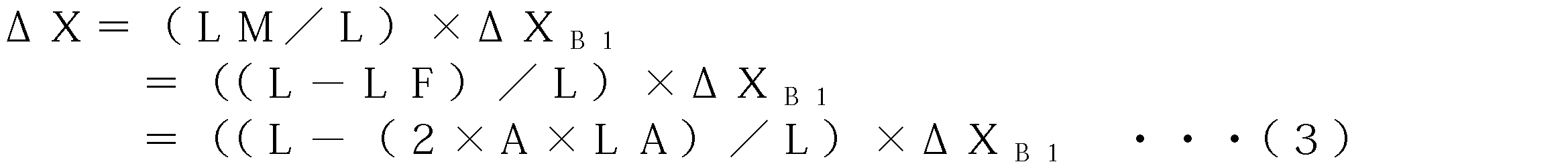
The optical path length LA per unit thickness of the intervening tissue B2, the measured substance change amount ΔX B1 in the measurement target region when only the concentration of the measured substance was changed, and only the measured substance obtained by measurement were changed. In this case, the relationship with the change amount ΔX before correction is expressed by the following equation (3).
更に、測定対象領域B1の同一部位における酸素消費量の個体差は殆ど無いという仮定のもと、次の処理を行う。一箇所での光入射及び一箇所での光検出によって取得された安静時の平均光路長Lと、この平均光路長Lから推定された介在組織厚さAと、被測定物質のみ変化させた際の被測定物質の補正前変化量ΔXとを使用して、複数人に関する上式(3)を用意する。更に上式(3)から導かれる次式(4)が最小となるような共通のLA(介在組織B2の単位厚さ当たりの光路長)及びΔXB1(測定対象領域B1の被測定物質化量)を単位光路長演算部414が算出する。

Further, the following processing is performed under the assumption that there is almost no individual difference in oxygen consumption at the same site in the measurement target region B1. When the average optical path length L at rest obtained by light incidence at one place and light detection at one place, the intervening tissue thickness A estimated from this average optical path length L, and only the substance to be measured are changed The above equation (3) for a plurality of persons is prepared using the change amount ΔX before correction of the substance to be measured. Furthermore, the common LA (the optical path length per unit thickness of the intervening tissue B2) and ΔX B1 (the amount of material to be measured in the measurement target region B1) that minimizes the following formula (4) derived from the above formula (3) ) Is calculated by the unit optical path length calculation unit 414.
記憶手段に、介在組織B2の厚さAと、被測定物質の濃度のみ変化させた場合の補正前変化量ΔXとの相関に関する情報が蓄積され、介在組織B2の単位厚さ当たりの光路長LAか決定されていれば、被験者毎に被測定物質の濃度のみを変化させる別計測を行う必要はなくなる。
Information on the correlation between the thickness A of the intervening tissue B2 and the amount of change ΔX before correction when only the concentration of the substance to be measured is changed is stored in the storage means, and the optical path length LA per unit thickness of the intervening tissue B2 is accumulated. If it is determined, it is not necessary to perform another measurement for changing only the concentration of the substance to be measured for each subject.
部分光路長演算部415は、散乱吸収体B全体を通過する平均光路長Lのうち、介在組織B2を通過する部分の光路長(部分光路長LF)を算出する。部分光路長演算部415は、例えば数式(2)を用いて、介在組織厚演算部413から提供された介在組織B2の厚さAと単位光路長演算部414から提供された介在組織B2の単位厚さ当たりの光路長LAから、部分光路長LFを求める。
The partial optical path length calculation unit 415 calculates the optical path length (partial optical path length LF) of the portion that passes through the intervening tissue B2 out of the average optical path length L that passes through the entire scattering medium B. The partial optical path length calculation unit 415 uses the formula (2), for example, the thickness A of the intervening tissue B2 provided from the intervening tissue thickness calculation unit 413 and the unit of the intervening tissue B2 provided from the unit optical path length calculation unit 414. The partial optical path length LF is obtained from the optical path length LA per thickness.
測定感度演算部416は、部分光路長LFに基づいて、式(1)で推定される測定感度(補正係数)Sを算出する。
The measurement sensitivity calculation unit 416 calculates the measurement sensitivity (correction coefficient) S estimated by Expression (1) based on the partial optical path length LF.
補正演算部417は、補正前変化量算出部411により算出された被測定物質(オキシヘモグロビン、デオキシヘモグロビン、トータルヘモグロビン)の変化量を、測定感度演算部416により算出された測定感度Sを用いて補正する。
The correction calculation unit 417 uses the measurement sensitivity S calculated by the measurement sensitivity calculation unit 416 for the change amount of the substance to be measured (oxyhemoglobin, deoxyhemoglobin, total hemoglobin) calculated by the pre-correction change amount calculation unit 411. to correct.
再び図1を参照する。表示部70は、本体部60に接続されている。表示部70は、必要に応じて介在組織B2の厚さAや補正後の被測定物質(オキシヘモグロビン、デオキシヘモグロビン、トータルヘモグロビン)の変化量を表示する。
Refer to FIG. 1 again. The display unit 70 is connected to the main body unit 60. The display unit 70 displays the change amount of the measured substance (oxyhemoglobin, deoxyhemoglobin, total hemoglobin) after the thickness A of the intervening tissue B2 and the correction as necessary.
上述した散乱吸収体測定装置1を用いた散乱吸収体測定方法について、詳細に説明する。図3は、平均光路長演算部412における平均光路長Lの算出方法を説明するための図である。図3において、縦軸は光量(対数目盛)を示し、横軸は時間を示している。グラフG11は、時刻t0に光入射手段10から散乱吸収体Bへ入射されるパルス光強度の時間波形(入射波形)である。グラフG12は、時刻t0に入射されたパルス光に対応する検出光強度の時間波形(検出波形)である。散乱吸収体Bの内部を伝搬した光が光検出位置Dに達する時間は、その伝搬状況によって一様ではなく、また、散乱吸収体Bでの散乱や吸収によって減衰を受ける。従って、図3のグラフG12に示されるように、検出波形は或る一定の分布曲線となる。時刻t0から検出波形の波形重心として算出される時刻t1までの平均伝播時間Tと光速cとの積によって、平均光路長L(=T×c)が算出される。なお、この計算において、時刻t0として入射波形の波形重心となる時刻が用いられてもよい。
A scattering absorber measuring method using the scattering absorber measuring apparatus 1 described above will be described in detail. FIG. 3 is a diagram for explaining a method of calculating the average optical path length L in the average optical path length calculation unit 412. In FIG. 3, the vertical axis indicates the amount of light (logarithmic scale), and the horizontal axis indicates time. Graph G11 is the time waveform of the pulsed light intensity incident from the light projecting means 10 to the scattering medium B at time t 0 (the incident wave). Graph G12 is the time waveform of the detected light intensity corresponding to the incident pulsed light at time t 0 (detection waveform). The time that the light propagated inside the scattering medium B reaches the light detection position D is not uniform depending on the propagation state, and is attenuated by scattering and absorption in the scattering medium B. Therefore, as shown in the graph G12 of FIG. 3, the detected waveform is a certain distribution curve. The average optical path length L (= T × c) is calculated by the product of the average propagation time T and the speed of light c from time t 0 to time t 1 calculated as the waveform centroid of the detected waveform. Incidentally, in this calculation, the time at which the waveform center of gravity of the incident wave as the time t 0 may be used.
図4は、このような方法を使用して実際に測定された平均光路長Lと、超音波装置を用いて計測された介在組織(脂肪)B2の厚さAとの関係をプロットしたグラフである。図4において、縦軸は介在組織厚さA(cm)を示し、横軸は平均光路長L(cm)を示している。また、図4において、黒丸のプロットは散乱吸収体Bが前腕部(N=36、但しNは被験者数である。)である場合を示しており、正方形のプロットは散乱吸収体Bが大腿部(N=11、大腿部を複数箇所計測)である場合を示している。
FIG. 4 is a graph plotting the relationship between the average optical path length L actually measured using such a method and the thickness A of the intervening tissue (fat) B2 measured using the ultrasonic device. is there. In FIG. 4, the vertical axis represents the intervening tissue thickness A (cm), and the horizontal axis represents the average optical path length L (cm). In FIG. 4, the black circle plot shows the case where the scatter absorber B is the forearm (N = 36, where N is the number of subjects), and the square plot shows the scatter absorber B is the thigh. Part (N = 11, thighs are measured at a plurality of locations).
図4に示されるように、介在組織厚さAが厚いほど、平均光路長Lが長くなることがわかる。介在組織厚さAと平均光路長Lとの相関は、例えば図4に示された近似直線L1によって好適に表される。なお、この近似直線L1は次の式(5)によって表され、そのR2値は0.7391であった。なお、この関係式は式(5)に限定されるものではなく、データ数が増えることによって、近似式が変わってもよい。

As FIG. 4 shows, it turns out that the average optical path length L becomes long, so that the intervening tissue thickness A is thick. The correlation between the intervening tissue thickness A and the average optical path length L is suitably represented by, for example, the approximate straight line L1 shown in FIG. The approximate straight line L1 is represented by the following equation (5), and its R 2 value was 0.7391. Note that this relational expression is not limited to Expression (5), and the approximate expression may change as the number of data increases.
上記関係式(5)に基づいて、平均光路長Lから介在組織B2の厚さAを推定することができる。本実施形態では、平均光路長演算部412によって得られた平均光路長Lと上記式(5)とを用いて、介在組織厚演算部413において介在組織B2の厚さAが推定される。なお、従来のCW計測では、平均光路長を測定できず、光ファイバー間距離に対する定数(Differential Pathlength Factor;DPF)値を用いる。したがって、平均光路長に個体差はなく、規格化された値でしか平均光路長を取り扱うことができない。
Based on the relational expression (5), the thickness A of the intervening tissue B2 can be estimated from the average optical path length L. In the present embodiment, the interstitial tissue thickness calculator 413 estimates the thickness A of the intervening tissue B2 using the average optical path length L obtained by the average optical path length calculator 412 and the above equation (5). In the conventional CW measurement, the average optical path length cannot be measured, and a constant (DifferentialifPathlength Factor; DPF) value with respect to the distance between the optical fibers is used. Therefore, there is no individual difference in the average optical path length, and the average optical path length can be handled only with a standardized value.
図5及び図6それぞれは、前腕部(N=36)及び大腿部(N=7)それぞれを250mmHgで動脈駆血した場合における、被測定物質量(デオキシヘモグロビン量)の1分間あたりの変化量を測定した結果と、介在組織厚さAとの関係をプロットしたグラフである。図5及び図6において、縦軸はデオキシヘモグロビン量の変化量を示し、横軸は介在組織厚さAを示している。
FIG. 5 and FIG. 6 show changes per minute in the amount of substance to be measured (deoxyhemoglobin amount) when the forearm (N = 36) and thigh (N = 7) are arterial driven at 250 mmHg, respectively. It is the graph which plotted the relationship between the result of having measured quantity, and intervening tissue thickness A. FIG. 5 and 6, the vertical axis represents the amount of change in the amount of deoxyhemoglobin, and the horizontal axis represents the interstitial tissue thickness A.
駆血状態、すなわち血液の流出や流入がない状態では、筋肉の酸素消費によってオキシヘモグロビンが減少し、デオキシヘモグロビンが増加する。図5及び図6に示されるように、介在組織厚さAが厚くなるほど、デオキシヘモグロビン量の変化量の測定値は減少する。散乱吸収体Bの同じ部位での筋肉酸素消費量は個体差が小さいことから、介在組織厚さAが厚いほどデオキシヘモグロビン量の測定値が過少評価されていることがわかる。上述した散乱吸収体測定装置1では、補正演算部417において、この過小評価分を数式(1)に示した測定感度Sを用いて補正する。
In a state of blood pumping, that is, in a state where there is no outflow or inflow of blood, oxyhemoglobin decreases due to muscle oxygen consumption, and deoxyhemoglobin increases. As shown in FIGS. 5 and 6, as the intervening tissue thickness A increases, the measured value of the amount of change in the deoxyhemoglobin amount decreases. Since the muscle oxygen consumption at the same site of the scattering medium B has a small individual difference, it is understood that the measured value of deoxyhemoglobin is underestimated as the intervening tissue thickness A is thicker. In the scattering medium measuring apparatus 1 described above, the correction calculation unit 417 corrects the underestimated portion using the measurement sensitivity S shown in Equation (1).
ここで、測定感度演算部416において測定感度Sを求める際に、平均光路長Lのうち測定対象領域B1における部分光路長LMを推定することができれば、数式(1)によって測定感度Sを求めることができる。しかしながら、シミュレーションを用いると、部分光路長LMの推定は可能であるが、各構成要素(測定対象領域B1、介在組織B2等)の光学係数や厚さを仮定する必要があり、現実的ではない。これに対し、本実施形態では、平均光路長Lから介在組織厚さAを推定できるので、単位光路長演算部414にて、一箇所での光入射及び一箇所での光検出による計測データ、並びに平均光路長Lと被測定物質の変化量との関係から、介在組織B2の単位厚さ当たりの光路長LAを求めることができる。さらに、得られた介在組織B2の単位厚さ当たりの光路長LAと平均光路長Lと介在組織厚さAとを用いて、数式(1)及び(2)より、測定感度演算部416において、部分光路長LM及びLFを求め、更に測定感度Sを求めることができる。
Here, when the measurement sensitivity S is obtained by the measurement sensitivity calculation unit 416, if the partial optical path length LM in the measurement target region B1 in the average optical path length L can be estimated, the measurement sensitivity S is obtained by Expression (1). Can do. However, although the partial optical path length LM can be estimated using simulation, it is necessary to assume the optical coefficient and thickness of each component (measurement target region B1, intervening tissue B2, etc.), which is not realistic. . On the other hand, in this embodiment, since the intervening tissue thickness A can be estimated from the average optical path length L, the unit optical path length calculation unit 414 performs measurement data by light incidence at one place and light detection at one place, In addition, the optical path length LA per unit thickness of the intervening tissue B2 can be obtained from the relationship between the average optical path length L and the amount of change in the substance to be measured. Further, using the optical path length LA, the average optical path length L, and the intervening tissue thickness A per unit thickness of the intervening tissue B2 obtained, in the measurement sensitivity calculation unit 416, from Equations (1) and (2), The partial optical path lengths LM and LF can be obtained, and further the measurement sensitivity S can be obtained.
例えば測定対象領域B1が筋肉であり、介在組織B2が脂肪である場合、筋肉と比べて脂肪の血液量や酸素消費量は極めて小さいので、駆血時に、介在組織B2の血液量変化はほとんど生じていないと考えられる。一方、測定対象領域B1では酸素消費量が大きい。従って、駆血により増加する測定対象領域B1のデオキシヘモグロビン変化量ΔHbmと、測定により得られるデオキシヘモグロビン変化量ΔHbとの関係は、次の式(6)で表される。

For example, when the measurement target region B1 is muscle and the intervening tissue B2 is fat, the blood volume and oxygen consumption of fat are extremely small compared to the muscle. It is thought that it is not. On the other hand, the oxygen consumption is large in the measurement target region B1. Therefore, the relationship between the deoxyhemoglobin change amount ΔHbm in the measurement target region B1 that is increased by the blood pumping and the deoxyhemoglobin change amount ΔHb obtained by the measurement is expressed by the following equation (6).
更に、測定対象領域B1の同一部位における酸素消費量の個体差は殆ど無いという仮定のもと、一箇所での光入射及び一箇所での光検出によって取得した安静時の平均光路長Lと、この平均光路長Lから推定された介在組織厚さAと、駆血時のデオキシヘモグロビン変化量ΔHbとを使用して、複数人に関する上式(6)を用意する。そして、上式(6)から導かれる次式(7)が最小となるような共通のLA(介在組織B2の単位厚さ当たりの光路長)及びΔHbm(測定対象領域B1のデオキシヘモグロビン変化量)を単位光路長演算部414が算出する。これにより、得られた介在組織B2の単位厚さ当たりの光路長LAと平均光路長Lと介在組織厚さAとを用い、測定感度演算部416において、式(1)及び(2)から各被験者毎に測定感度Sを求めることができる。

Furthermore, under the assumption that there is almost no individual difference in oxygen consumption at the same part of the measurement target region B1, the average optical path length L at rest obtained by light incidence at one place and light detection at one place; Using the intervening tissue thickness A estimated from the average optical path length L and the deoxyhemoglobin change ΔHb at the time of blood transfusion, the above equation (6) for a plurality of persons is prepared. Then, the common LA (the optical path length per unit thickness of the intervening tissue B2) and ΔHbm (the amount of change in deoxyhemoglobin in the measurement target region B1) such that the following formula (7) derived from the above formula (6) is minimized. Is calculated by the unit optical path length calculation unit 414. As a result, using the obtained optical path length LA, average optical path length L, and intervening tissue thickness A per unit thickness of the intervening tissue B2, the measurement sensitivity calculation unit 416 uses the equations (1) and (2) to The measurement sensitivity S can be obtained for each subject.
なお、本実施形態による方法では、予め蓄積されたデータから介在組織厚さAまたは平均光路長Lと測定感度Sとの関係が導かれていれば、その関係式を用いればよいので、被験者毎に駆血などの負荷を与えずに済む。
In the method according to the present embodiment, if the relationship between the intervening tissue thickness A or the average optical path length L and the measurement sensitivity S is derived from the data accumulated in advance, the relational expression may be used. It is not necessary to give a load such as driving.
実際に、図5及び図6の測定データから前腕部及び大腿部のLF及びΔHbmを求めた。ΔHbmは、前腕部が23.11μM、大腿部が13.47μMと推定された。また、介在組織厚さ(脂肪厚さ)1cmに対する部分光路長LFは、前腕部が9.14cm、大腿部が9.57cmと推定された。
Actually, the LF and ΔHbm of the forearm and thigh were obtained from the measurement data shown in FIGS. ΔHbm was estimated to be 23.11 μM for the forearm and 13.47 μM for the thigh. The partial optical path length LF for the intervening tissue thickness (fat thickness) of 1 cm was estimated to be 9.14 cm for the forearm and 9.57 cm for the thigh.
ここで、図7は、実測された平均光路長Lと、上式(1)から得られた測定感度Sとの関係をプロットしたグラフである。図7において、縦軸は測定感度Sを示し、横軸は介在組織厚さAを示している。また、図7において、正方形のプロットは前腕部を示しており、三角形のプロットは大腿部を示しており、アスタリスク状のプロットは理論値を示している。なお、理論値の数式は、次のとおりである。

Here, FIG. 7 is a graph plotting the relationship between the actually measured average optical path length L and the measurement sensitivity S obtained from the above equation (1). In FIG. 7, the vertical axis represents the measurement sensitivity S, and the horizontal axis represents the intervening tissue thickness A. In FIG. 7, the square plot indicates the forearm, the triangle plot indicates the thigh, and the asterisk-shaped plot indicates the theoretical value. The mathematical formula of the theoretical value is as follows.
図7に示されるように、介在組織厚さAが厚くなるほど、測定感度Sは小さくなる。また、この図7の横軸を、上式(5)を使用して介在組織厚さAから平均光路長Lに置き換えることで、介在組織厚さAを計測しなくとも、平均光路長Lから測定感度Sを導くこともできる。なお、図2に示した測定感度演算部416では、測定感度Sと介在組織厚さAとの関係式から、本測定時に適用される測定感度Sを算出する。
As shown in FIG. 7, the measurement sensitivity S decreases as the intervening tissue thickness A increases. Further, by replacing the horizontal axis of FIG. 7 with the average optical path length L from the intervening tissue thickness A using the above equation (5), the average optical path length L can be calculated without measuring the intervening tissue thickness A. The measurement sensitivity S can also be derived. Note that the measurement sensitivity calculation unit 416 shown in FIG. 2 calculates the measurement sensitivity S applied during the actual measurement from the relational expression between the measurement sensitivity S and the intervening tissue thickness A.
そして、最終的に、補正演算部417において、被測定物質の量に関する測定値(例えばデオキシヘモグロビン変化量ΔHb)を測定感度Sで除することにより、介在組織B2の影響を除いた測定対象領域B1の値(例えば測定対象領域B1のデオキシヘモグロビン変化量ΔHbm)を推定することができる。
Finally, the correction calculation unit 417 divides the measurement value (for example, deoxyhemoglobin change amount ΔHb) related to the amount of the substance to be measured by the measurement sensitivity S, thereby removing the measurement target region B1 from the influence of the intervening tissue B2. (For example, deoxyhemoglobin change amount ΔHbm of the measurement target region B1) can be estimated.
上記方法によって、介在組織B2における単位長さ(1cm)当たりの部分光路長LAは例えば平均約9.4cmであることが推定された。従って、平均光路長Lを測定し、この平均光路長Lから介在組織厚さAを推測し、推定された部分光路長LAの数値と共に上式(2)にこれらを当てはめることで、介在組織B2の部分光路長LFを算出できる。そして、この部分光路長LFを用いて、上式(1)から測定対象領域B1内部の寄与率を推定し、測定感度Sを求めることができる。
By the above method, it was estimated that the partial optical path length LA per unit length (1 cm) in the intervening tissue B2 was, for example, an average of about 9.4 cm. Therefore, by measuring the average optical path length L, estimating the intervening tissue thickness A from the average optical path length L, and applying these to the above formula (2) together with the numerical value of the estimated partial optical path length LA, the intervening tissue B2 The partial optical path length LF can be calculated. Then, using this partial optical path length LF, the contribution rate inside the measurement target region B1 can be estimated from the above equation (1), and the measurement sensitivity S can be obtained.
また、図7の横軸を平均光路長Lに換算すると、図8に示すようなグラフとなる。図8は、平均光路長Lと測定感度Sとの相関を表しており、平均光路長Lが長くなるほど測定感度Sが小さくなっていることがわかる。つまり、安静時の平均光路長Lを測定すれば、測定感度Sを導くことができるので、超音波測定などの方法を用いて介在組織厚さAを測定する必要がない。また、図8には、介在組織厚さAがゼロのときに測定感度Sが1となるような理論曲線L2が併せて示されている。この理論曲線L2の関数を次の式(9)に示す。なお、測定感度Sの推定に用いる関係式はこの理論曲線L2に限定されるものではなく、最適な近似式を使用してもよい。

Further, when the horizontal axis in FIG. 7 is converted into the average optical path length L, a graph as shown in FIG. 8 is obtained. FIG. 8 shows the correlation between the average optical path length L and the measurement sensitivity S, and it can be seen that the measurement sensitivity S decreases as the average optical path length L increases. That is, if the average optical path length L at rest is measured, the measurement sensitivity S can be derived, and therefore there is no need to measure the intervening tissue thickness A using a method such as ultrasonic measurement. FIG. 8 also shows a theoretical curve L2 in which the measurement sensitivity S is 1 when the intervening tissue thickness A is zero. The function of this theoretical curve L2 is shown in the following equation (9). The relational expression used for estimating the measurement sensitivity S is not limited to the theoretical curve L2, and an optimal approximate expression may be used.
ここで、上述した平均光路長Lによる測定値の補正が適切か否かを検証する為に、時間分解分光システム(TRS)による測定と、プレチスモグラフィによる測定とを同時に実施した結果(但し、N=14)について説明する。プレチスモグラフィとは、測定部位(例えば前腕部)に対して静脈駆血を行い、流入し続ける動脈血流によって増加する当該部位の容積を種々の方法で測定するものである。一方、TRSでは、測定部位を静脈駆血した際の単位時間当たりの被測定物質(例えばヘモグロビン)の変化量を血流量とみなすことができる。従って、TRSにより計測した平均光路長Lに基づき、上述した方法を使用して介在組織(脂肪)厚さA及び測定感度Sを推定し、この測定感度Sを用いてTRS測定値(血流値)を補正し、この補正値と、プレチスモグラフィによる測定値との比較を行なった。
Here, in order to verify whether or not the correction of the measurement value based on the average optical path length L described above is appropriate, the result of performing the measurement by the time-resolved spectroscopy system (TRS) and the measurement by the plethysmography at the same time (however, N = 14) will be described. In plethysmography, venous blood is fed to a measurement site (for example, the forearm), and the volume of the site that increases due to arterial blood flow that continues to flow is measured by various methods. On the other hand, in TRS, the amount of change in the substance to be measured (for example, hemoglobin) per unit time when the measurement site is venous driven can be regarded as the blood flow rate. Therefore, based on the average optical path length L measured by TRS, the interstitial tissue (fat) thickness A and measurement sensitivity S are estimated using the above-described method, and the TRS measurement value (blood flow value) is calculated using this measurement sensitivity S. ) Was corrected, and the corrected value was compared with the measured value by plethysmography.
まず、プロトコールとして、10秒間の前腕部静脈駆血(40mmHg)、及び10秒間の駆血解除を3セット行った。このときの血流量を、安静時血流量(すなわち初期値)とした。続けて、3分間の動静脈駆血(250mmHg)を行った。そして3分間の駆血解除後、引き続き、10秒間の静脈駆血(40mmHg)及び10秒間の駆血解除を数回繰り返した。なお、3分間の動静脈駆血後の反応は反応性充血と呼ばれ、血流再開後の血流量が駆血前の安静時血流量から何倍も増加する。従って、一個体内で様々な血流量データの取得が可能となる。
First, as a protocol, 3 sets of forearm venous blood transfusion (40 mmHg) for 10 seconds and blood transfusion release for 10 seconds were performed. The blood flow at this time was defined as a resting blood flow (that is, an initial value). Subsequently, arteriovenous blood was fed for 3 minutes (250 mmHg). Then, after 3 minutes of releasing the blood transfusion, 10 seconds of venous blood transportation (40 mmHg) and 10 seconds of blood release were repeated several times. The reaction after 3 minutes of arteriovenous exsanguination is called reactive hyperemia, and the blood flow after resumption of blood flow increases many times from the resting blood flow before the blood transfusion. Accordingly, various blood flow data can be acquired within one individual.
図9は、実際にこのプロトコールを行なったときの、TRS測定結果(血流変化量)の典型例を示すグラフである。図9において、縦軸はヘモグロビン濃度の変化量(μM)を示しており、横軸は時間(分)を示している。また、グラフG21はオキシヘモグロビン(HbO2)量を示しており、グラフG22はデオキシヘモグロビン(Hb)量を示しており、グラフG23は総ヘモグロビン(tHb)量を示している。
FIG. 9 is a graph showing a typical example of the TRS measurement result (blood flow change amount) when this protocol is actually performed. In FIG. 9, the vertical axis represents the amount of change (μM) in hemoglobin concentration, and the horizontal axis represents time (minutes). Graph G21 indicates the amount of oxyhemoglobin (HbO 2 ), graph G22 indicates the amount of deoxyhemoglobin (Hb), and graph G23 indicates the amount of total hemoglobin (tHb).
また、図10は、14名の平均光路長L、平均光路長Lより推定された介在組織厚さA、部分光路長LFより推定された測定感度Sを示す図表である。図10に示される測定感度Sで、補正前のTRSによる血流量測定値を除することにより、補正後の血流量測定値を求めた。
FIG. 10 is a chart showing the average optical path length L of 14 persons, the interstitial tissue thickness A estimated from the average optical path length L, and the measurement sensitivity S estimated from the partial optical path length LF. The blood flow rate measurement value after correction was obtained by dividing the blood flow rate measurement value by TRS before correction with the measurement sensitivity S shown in FIG.
図11及び図12は、TRSによる血流量測定値と、プレチスモグラフィによる血流量測定値との相関をプロットしたグラフである。図11は、補正前におけるこれらの相関を示しており、図12は測定感度Sにより補正した場合のこれらの相関を示している。なお、図11及び図12において、縦軸はTRSによる血流量測定値を示しており、横軸はプレチスモグラフィによる血流量測定値を示している。血流量の単位は、プレチスモグラフィに合わせて(ml/min/100g)に換算している。
FIG. 11 and FIG. 12 are graphs plotting the correlation between the blood flow measurement value by TRS and the blood flow measurement value by plethysmography. FIG. 11 shows these correlations before correction, and FIG. 12 shows these correlations when corrected by the measurement sensitivity S. 11 and 12, the vertical axis represents the blood flow measurement value by TRS, and the horizontal axis represents the blood flow measurement value by plethysmography. The unit of blood flow is converted to (ml / min / 100 g) according to the plethysmography.
図11に示されるように、補正前においては、近似直線L3のプレチスモグラフィ値に対するTRS値の傾きは0.4であった。これに対し、図12に示されるように、測定感度Sによる補正後は近似直線L4の傾きがほぼ1となり、TRS値がプレチスモグラフィ値に近づいた。
As shown in FIG. 11, before the correction, the slope of the TRS value with respect to the plethysmographic value of the approximate straight line L3 was 0.4. On the other hand, as shown in FIG. 12, after the correction by the measurement sensitivity S, the slope of the approximate straight line L4 is almost 1, and the TRS value approaches the plethysmography value.
以上のことから、介在組織厚さA又は平均光路長Lと測定感度Sとの相関が得られた状況において、平均光路長Lさえ測定すれば、被測定物質の量に関するデータの感度補正が可能となる。
From the above, in the situation where the correlation between the interstitial tissue thickness A or the average optical path length L and the measurement sensitivity S is obtained, if only the average optical path length L is measured, the sensitivity correction of the data relating to the amount of the substance to be measured is possible. It becomes.
なお、上述した方法では血流量の測定を例に挙げた。運動時の筋肉代謝に関する測定を行う際には、安静状態での測定をまず行って平均光路長Lから介在組織厚さAや測定感度Sを算出し、引き続き運動を行った際の血液変化量を測定感度Sにより補正した値を表示部70に表示させるとよい。これによって、被測定者はリアルタイムで(脂肪の影響を除外した)筋肉の血液変化量を確認することができる。また、被測定者は脂肪厚も知ることができる。
In the above method, measurement of blood flow is taken as an example. When measuring the muscle metabolism during exercise, the measurement in the resting state is first performed, the interstitial tissue thickness A and the measurement sensitivity S are calculated from the average optical path length L, and the amount of blood change when exercise continues It is good to display the value which correct | amended by measurement sensitivity S on the display part 70. FIG. As a result, the measurement subject can confirm the amount of blood change in the muscle (excluding the influence of fat) in real time. The subject can also know the fat thickness.
図13は、以上に述べた散乱吸収体測定方法の処理の流れを示すフローチャートである。すなわち、本実施形態の散乱吸収体測定方法においては、図1に示したように、まず散乱吸収体Bの表面Baに設定された一つの光入射位置Iから所定波長のパルス光Pを入射する(光入射ステップS1)。次に、散乱吸収体Bの内部を伝搬したパルス光Pを、散乱吸収体Bの表面Baに設定された一つの光検出位置Dで検出して光検出信号を得る(光検出ステップS2)。
FIG. 13 is a flowchart showing a processing flow of the scattering medium measuring method described above. That is, in the scattering medium measuring method of this embodiment, as shown in FIG. 1, first, pulsed light P having a predetermined wavelength is incident from one light incident position I set on the surface Ba of the scattering medium B. (Light incident step S1). Next, the pulsed light P propagated inside the scattering medium B is detected at one light detection position D set on the surface Ba of the scattering medium B to obtain a light detection signal (light detection step S2).
続いて、この光検出信号に基づいて、検出光の光強度についての時間波形を取得する(信号処理ステップS3)。そして、この時間波形に基づいて、散乱吸収体Bの内部における平均光路長Lと、測定対象領域B1における被測定物質の量に関連する情報(変化量など)とを演算する(演算ステップS4)。この演算ステップS4においては、平均光路長Lが長いほど被測定物質の量が多くなるように、平均光路長Lに基づいて、被測定物質の量に関連する情報を補正する。例えば、平均光路長Lが長くなるほど介在組織厚さAが厚くなるので(図4を参照)、予め取得しておいたこのような相関に基づいて、被測定物質の量に関連する情報を補正するとよい。或いは、平均光路長Lが長くなるほど測定感度Sが小さくなるので(図8を参照)、予め取得しておいたこのような相関に基づいて、被測定物質の量に関連する情報を補正してもよい。或いは、予め取得しておいた、介在組織B2の単位厚さ当たりの光路長LAに基づいて、被測定物質の量に関連する情報を補正してもよい。なお、介在組織B2の単位厚さ当たりの光路長LAは、被測定物質のみ変化させたときの被測定物質変化量と介在組織B2の厚さとの関係より得られる。
Subsequently, a time waveform about the light intensity of the detection light is acquired based on the light detection signal (signal processing step S3). Based on this time waveform, the average optical path length L inside the scattering medium B and the information (change amount etc.) related to the amount of the substance to be measured in the measurement target region B1 are calculated (calculation step S4). . In this calculation step S4, information related to the amount of the substance to be measured is corrected based on the average optical path length L so that the amount of the substance to be measured increases as the average optical path length L increases. For example, since the interstitial tissue thickness A increases as the average optical path length L increases (see FIG. 4), information related to the amount of the substance to be measured is corrected based on such correlation acquired in advance. Good. Alternatively, since the measurement sensitivity S decreases as the average optical path length L increases (see FIG. 8), information related to the amount of the substance to be measured is corrected based on such a correlation acquired in advance. Also good. Or you may correct | amend the information relevant to the quantity of a to-be-measured substance based on the optical path length LA per unit thickness of intervening tissue B2 which was acquired previously. The optical path length LA per unit thickness of the intervening tissue B2 is obtained from the relationship between the amount of change in the substance to be measured when only the substance to be measured is changed and the thickness of the intervening tissue B2.
或いは、予め取得しておいた、平均光路長Lと測定感度Sとの相関に基づいて、被測定物質の量に関連する情報を補正してもよい。この場合、平均光路長Lと測定感度Sとの相関は、散乱吸収体Bの内部における平均光路長Lのうち介在組織B2又は測定対象領域B1を通過する部分の光路長(部分光路長LM又はLF)と、平均光路長Lとから求められる。
Alternatively, based on the correlation between the average optical path length L and the measurement sensitivity S acquired in advance, information related to the amount of the substance to be measured may be corrected. In this case, the correlation between the average optical path length L and the measurement sensitivity S is the optical path length (partial optical path length LM or partial optical path length LM or part of the average optical path length L inside the scattering medium B that passes through the intervening tissue B2 or the measurement target region B1. LF) and the average optical path length L.
或いは、散乱吸収体Bの内部における平均光路長Lのうち介在組織B2の部分光路長LFを、介在組織B2の単位厚さ当たりの光路長LAと、予め取得しておいた平均光路長L及び介在組織厚さAの相関から得られる介在組織厚さAとに基づいて推定し、推定した該部分光路長LFから測定感度Sを求め、被測定物質の量に関連する情報を該測定感度Sを用いて補正してもよい。
Alternatively, among the average optical path length L inside the scattering medium B, the partial optical path length LF of the intervening tissue B2 is calculated by using the optical path length LA per unit thickness of the intervening tissue B2 and the previously acquired average optical path length L and Based on the intervening tissue thickness A obtained from the correlation of the intervening tissue thickness A, the measurement sensitivity S is obtained from the estimated partial optical path length LF, and information related to the amount of the substance to be measured is obtained. You may correct using.
以上に説明した散乱吸収体測定方法によって、次の効果が得られる。すなわち、この方法によれば、平均光路長Lから介在組織厚さAを推定できるので、超音波装置等を用いて介在組織厚さAを実測しなくても、測定対象領域B1の被測定物質の量に関する情報を正確に求めることができる。従って、被測定者や測定部位によって異なる介在組織厚さAに関係なく、被測定物質の量に関する情報の比較が可能となる。
The following effects can be obtained by the scattering absorber measurement method described above. That is, according to this method, since the intervening tissue thickness A can be estimated from the average optical path length L, the substance to be measured in the measurement target region B1 can be obtained without actually measuring the intervening tissue thickness A using an ultrasonic device or the like. It is possible to accurately obtain information on the quantity of Therefore, it becomes possible to compare information on the amount of the substance to be measured regardless of the intervening tissue thickness A which varies depending on the person to be measured and the measurement site.
本発明による散乱吸収体測定方法及び装置は、上述した実施形態に限られるものではなく、他に様々な変形が可能である。例えば、上記実施形態では本発明を時間分解計測法に適用した場合について説明したが、上記実施形態は、平均光路長を測定できる他の手法、例えば位相差法にも適用可能である。また、CW法のような平均光路長を計測できない手法であっても、事前に時間分解分光法などによって平均光路長Lを計測してあれば、そのような手法による計測結果に対しても補正を行うことができる。
The scattering medium measuring method and apparatus according to the present invention are not limited to the above-described embodiments, and various other modifications are possible. For example, although the case where the present invention is applied to the time-resolved measurement method has been described in the above embodiment, the above embodiment can also be applied to other methods that can measure the average optical path length, for example, the phase difference method. Even if the average optical path length cannot be measured as in the CW method, if the average optical path length L is measured in advance by time-resolved spectroscopy or the like, the measurement result by such a technique is also corrected. It can be performed.
また、上記実施形態では、測定値の補正をリアルタイムで行う場合について説明したが、測定終了後に補正を行ってもよい。また、上記実施形態において示された介在組織厚さと平均光路長との相関はあくまで一例である。また、補正に用いられる数式は、多様な補正関係式に適用できる。また、上記実施形態では安静時に測定した平均光路長を用いているが、安静時に限られるものではなく、測定条件が揃っていればよい。また、上記実施形態では、単位光路長演算部414において用いられる、被測定物質の濃度のみ変化させた場合の補正前変化量を計測するために被測定物質のみを変化させる方法として、駆血を用いている。しかしながら、被測定物質のみを変化させる方法はこれに限られず、上記条件を満たせばよく、薬剤によるものでもよいし、シミュレーションでもよい。
In the above embodiment, the case where the measurement value is corrected in real time has been described. However, the correction may be performed after the measurement is completed. The correlation between the intervening tissue thickness and the average optical path length shown in the above embodiment is merely an example. Further, the mathematical formula used for correction can be applied to various correction relational expressions. Moreover, although the average optical path length measured at the time of rest is used in the said embodiment, it is not restricted at the time of rest, What is necessary is just to have measurement conditions. Further, in the above embodiment, as a method of changing only the substance to be measured in order to measure the amount of change before correction when only the concentration of the substance to be measured is used, which is used in the unit optical path length calculation unit 414, blood excision is used. Used. However, the method of changing only the substance to be measured is not limited to this, and it is sufficient if the above conditions are satisfied.
また、上記実施形態では、被測定物質としてヘモグロビン(オキシヘモグロビン、デオキシヘモグロビン、総ヘモグロビン)を例示したが、所定波長の光を吸収する物質であれば、他の物質であってもよい。また、上記実施形態では、既に算出された血液変化量に対して測定感度で除する補正を行なったが、ヘモグロビン換算前の吸収係数変化量を補正してもよい。補正後の吸収係数変化量からヘモグロビンへ換算することで、補正後のヘモグロビンとして取り扱うことができる。
In the above embodiment, hemoglobin (oxyhemoglobin, deoxyhemoglobin, total hemoglobin) is exemplified as the substance to be measured, but other substances may be used as long as they absorb light of a predetermined wavelength. In the above-described embodiment, correction is performed by dividing the already calculated blood change amount by the measurement sensitivity. However, the absorption coefficient change amount before hemoglobin conversion may be corrected. By converting the corrected absorption coefficient change amount into hemoglobin, the corrected hemoglobin can be handled.
また、上記実施形態における補正は吸収変化量に対するものであるが、拡散方程式から得られた定量値に相対変化量を加えることにより、定量的な値として取り扱ってもよい。これにより、酸素飽和度(SO2)の算出も可能となる。
The correction in the above embodiment is for the absorption change amount, but may be handled as a quantitative value by adding a relative change amount to the quantitative value obtained from the diffusion equation. Thus, it becomes possible to calculate the oxygen saturation (SO 2).
また、上記実施形態では測定対象領域として筋肉を例示し、介在組織として脂肪を例示したが、測定対象領域及び介在組織はこれらに限定されるものではない。例えば、頭を測定する際には、測定対象領域を脳組織とし、介在組織を頭蓋等とする等、様々な多層構造組織に上記実施形態を適用できる。
In the above embodiment, muscle is exemplified as the measurement target region and fat is exemplified as the intervening tissue. However, the measurement target region and the intervening tissue are not limited to these. For example, when measuring the head, the above-described embodiment can be applied to various multilayer structures such as a brain tissue as a measurement target region and a skull as an intervening tissue.
また、上記実施形態では平均光路長と介在組織厚さとの関係を利用したが、例えば図14に示されるような、散乱係数と介在組織厚さとの関係を利用して測定値を補正しても良い。図14に示されるように、介在組織厚さが厚くなるほど散乱係数が大きくなっており、この相関に基づいて(或いは、この介在組織厚さを平均光路長に置き換えた相関に基づいて)、測定値を好適に補正することができる。
In the above embodiment, the relationship between the average optical path length and the intervening tissue thickness is used. However, even if the measurement value is corrected using the relationship between the scattering coefficient and the intervening tissue thickness as shown in FIG. good. As shown in FIG. 14, the scattering coefficient increases as the intervening tissue thickness increases. Based on this correlation (or based on the correlation in which the intervening tissue thickness is replaced with the average optical path length), the measurement is performed. The value can be corrected appropriately.
また、上記実施形態による測定方法によれば、平均光路長から介在組織厚さを推定できる。従って、測定対象領域における測定対象物質の量に関する情報を補正する以外にも、例えば、介在組織厚さを計測する従来法(超音波装置など)にかわり、介在組織厚さを計測することもできる。
In addition, according to the measurement method according to the above embodiment, the thickness of the intervening tissue can be estimated from the average optical path length. Therefore, in addition to correcting the information regarding the amount of the measurement target substance in the measurement target region, for example, instead of the conventional method (such as an ultrasonic device) for measuring the thickness of the intervening tissue, the thickness of the intervening tissue can also be measured. .
本発明は、介在組織の影響を除いた測定結果を簡易な方法によって得ることが可能な散乱吸収体測定方法及び装置として利用可能である。
The present invention can be used as a scattering absorber measurement method and apparatus capable of obtaining measurement results excluding the influence of intervening tissues by a simple method.
1…散乱吸収体測定装置、10…光入射手段、11…パルス光源、12…光入射用光ガイド、20…光検出手段、21…光検出用光ガイド、22…光検出器、30…信号処理手段、31…時間波形計測部、40…演算手段、41…演算処理部、50…制御部分、60…本体部、70…表示装置、411…補正前変化量算出部、412…平均光路長演算部、413…介在組織厚演算部、414…単位光路長演算部、415…部分光路長演算部、416…測定感度演算部、417…補正演算部、B…散乱吸収体、B1…測定対象領域、B2…介在組織、Ba…表面、D…光検出位置、P…パルス光、I…光入射位置。
DESCRIPTION OF SYMBOLS 1 ... Scattering absorber measuring apparatus, 10 ... Light incident means, 11 ... Pulse light source, 12 ... Light guide for light incidence, 20 ... Light detection means, 21 ... Light guide for light detection, 22 ... Light detector, 30 ... Signal Processing means 31 ... Time waveform measuring section 40 ... Calculating means 41 ... Calculation processing section 50 ... Control section 60 ... Main body section 70 ... Display device 411 ... Change amount calculator before correction 412 ... Average optical path length Calculation unit, 413 ... Intervening tissue thickness calculation unit, 414 ... Unit optical path length calculation unit, 415 ... Partial optical path length calculation unit, 416 ... Measurement sensitivity calculation unit, 417 ... Correction calculation unit, B ... Scattering absorber, B1 ... Measurement object Area, B2 ... intervening tissue, Ba ... surface, D ... light detection position, P ... pulse light, I ... light incident position.
Claims (16)
- 測定対象領域、及び前記測定対象領域と表面との間に存在する介在組織を含む散乱吸収体の前記測定対象領域における被測定物質の量に関連する情報を非侵襲的に測定する方法であって、
前記散乱吸収体の前記表面に設定された一つの光入射位置から所定波長の光を入射する光入射ステップと、
前記散乱吸収体内部を伝搬した前記所定波長の光を、前記散乱吸収体の前記表面に設定された一つの光検出位置で検出して光検出信号を得る光検出ステップと、
前記光検出信号に基づいて、検出光の光強度についての時間波形を取得する信号処理ステップと、
前記時間波形に基づいて、前記散乱吸収体内部における前記所定波長の光の平均光路長と、前記測定対象領域における前記被測定物質の量に関連する情報とを演算する演算ステップと
を備え、
前記演算ステップにおいて、前記平均光路長が長いほど前記被測定物質の量が多くなるように、前記平均光路長に基づいて前記被測定物質の量に関連する情報を補正する、散乱吸収体測定方法。 A method for non-invasively measuring information related to the amount of a substance to be measured in a measurement target region of a scattering medium including a measurement target region and an intervening tissue existing between the measurement target region and a surface. ,
A light incident step of entering light of a predetermined wavelength from one light incident position set on the surface of the scattering medium;
A light detection step of detecting the light of the predetermined wavelength propagated inside the scattering medium at one light detection position set on the surface of the scattering medium to obtain a light detection signal;
Based on the light detection signal, a signal processing step for obtaining a time waveform about the light intensity of the detection light;
Based on the time waveform, comprising calculating the average optical path length of the light of the predetermined wavelength inside the scattering medium and information related to the amount of the substance to be measured in the measurement target region,
In the calculation step, the scattering absorber measurement method corrects information related to the amount of the substance to be measured based on the average optical path length so that the amount of the substance to be measured increases as the average optical path length increases. . - 前記演算ステップにおいて、予め取得しておいた、前記平均光路長と前記介在組織の厚さとの相関に基づいて、前記被測定物質の量に関連する情報を補正する、請求項1に記載の散乱吸収体測定方法。 2. The scattering according to claim 1, wherein in the calculation step, information related to the amount of the substance to be measured is corrected based on a correlation between the average optical path length and the thickness of the intervening tissue acquired in advance. Absorber measurement method.
- 前記平均光路長と前記介在組織の厚さとの相関は、前記平均光路長が長くなるほど前記介在組織が厚くなる関係である、請求項2に記載の散乱吸収体測定方法。 3. The scattering medium measuring method according to claim 2, wherein the correlation between the average optical path length and the thickness of the intervening tissue is a relationship in which the intervening tissue becomes thicker as the average optical path length becomes longer.
- 前記演算ステップにおいて、予め取得しておいた、前記介在組織の単位厚さ当たりの光路長に基づいて、前記被測定物質の量に関連する情報を補正する、請求項1に記載の散乱吸収体測定方法。 The scattering medium according to claim 1, wherein in the calculation step, information related to the amount of the substance to be measured is corrected based on an optical path length per unit thickness of the intervening tissue acquired in advance. Measuring method.
- 前記演算ステップにおいて、予め取得しておいた、前記平均光路長と測定感度との相関に基づいて、前記被測定物質の量に関連する情報を補正する、請求項1に記載の散乱吸収体測定方法。 2. The scattering medium measurement according to claim 1, wherein in the calculation step, information related to the amount of the substance to be measured is corrected based on a correlation between the average optical path length and measurement sensitivity acquired in advance. Method.
- 前記演算ステップにおいて、前記平均光路長と前記測定感度との相関を、前記散乱吸収体内部における前記平均光路長のうち前記介在組織又は前記測定対象領域を通過する部分の光路長と、前記平均光路長とから求める、請求項5に記載の散乱吸収体測定方法。 In the calculation step, the correlation between the average optical path length and the measurement sensitivity is calculated by calculating the correlation between the average optical path length in the scattering medium and the average optical path length of the portion that passes through the intervening tissue or the measurement target region. The method for measuring a scattering medium according to claim 5, wherein the method is determined from the length.
- 前記演算ステップにおいて、前記散乱吸収体内部における前記平均光路長のうち前記介在組織を通過する部分の光路長を、前記介在組織の単位厚さ当たりの光路長と、予め取得しておいた前記平均光路長と前記介在組織の厚さとの相関から得られる前記介在組織の厚さとに基づいて推定し、推定した該光路長から測定感度を求め、前記被測定物質の量に関連する情報を該測定感度を用いて補正する、請求項1に記載の散乱吸収体測定方法。 In the calculating step, the optical path length of the portion passing through the intervening tissue among the average optical path length inside the scattering medium, the optical path length per unit thickness of the intervening tissue, and the average obtained in advance. Estimating based on the thickness of the intervening tissue obtained from the correlation between the optical path length and the thickness of the intervening tissue, obtaining measurement sensitivity from the estimated optical path length, and measuring information related to the amount of the substance to be measured The method of measuring a scattering medium according to claim 1, wherein correction is performed using sensitivity.
- 前記測定対象領域は筋肉であり、前記介在組織は脂肪である、請求項1~4のいずれか一項に記載の散乱吸収体測定方法。 The method of measuring a scattering medium according to any one of claims 1 to 4, wherein the measurement target region is muscle and the intervening tissue is fat.
- 測定対象領域、及び前記測定対象領域と表面との間に存在する介在組織を含む散乱吸収体の前記測定対象領域における被測定物質の量に関連する情報を非侵襲的に測定する装置であって、
前記散乱吸収体の前記表面に設定された一つの光入射位置から所定波長の光を入射する光入射手段と、
前記散乱吸収体内部を伝搬した前記所定波長の光を、前記散乱吸収体の前記表面に設定された一つの光検出位置で検出して光検出信号を生成する光検出手段と、
前記光検出信号に基づいて、検出光の光強度についての時間波形を取得する信号処理手段と、
前記時間波形に基づいて、前記散乱吸収体内部における前記所定波長の光の平均光路長と、前記測定対象領域における前記被測定物質の量に関連する情報とを演算する演算手段と
を備え、
前記演算手段は、前記平均光路長が長いほど前記被測定物質の量が多くなるように、前記平均光路長に基づいて前記被測定物質の量に関連する情報を補正する、散乱吸収体測定装置。 An apparatus for non-invasively measuring information related to the amount of a substance to be measured in a measurement target region of a scattering medium including a measurement target region and an intervening tissue existing between the measurement target region and a surface. ,
A light incident means for entering light of a predetermined wavelength from one light incident position set on the surface of the scattering medium;
A light detection means for generating a light detection signal by detecting the light having the predetermined wavelength propagated inside the scattering medium at one light detection position set on the surface of the scattering medium;
Based on the light detection signal, signal processing means for acquiring a time waveform about the light intensity of the detection light;
Based on the time waveform, comprising an arithmetic means for calculating an average optical path length of the light of the predetermined wavelength inside the scattering medium and information related to the amount of the substance to be measured in the measurement target region,
The calculation means corrects information related to the amount of the substance to be measured based on the average optical path length so that the amount of the substance to be measured increases as the average optical path length increases. . - 前記演算手段は、予め取得しておいた、前記平均光路長と前記介在組織の厚さとの相関に基づいて、前記被測定物質の量に関連する情報を補正する、請求項9に記載の散乱吸収体測定装置。 The scattering according to claim 9, wherein the calculation means corrects information related to the amount of the substance to be measured based on a correlation between the average optical path length and the thickness of the intervening tissue that has been acquired in advance. Absorber measuring device.
- 前記平均光路長と前記介在組織の厚さとの相関は、前記平均光路長が長くなるほど前記介在組織が厚くなる関係である、請求項10に記載の散乱吸収体測定装置。 The scattering medium measuring apparatus according to claim 10, wherein the correlation between the average optical path length and the thickness of the intervening tissue is a relationship in which the intervening tissue becomes thicker as the average optical path length becomes longer.
- 前記演算手段は、予め取得しておいた、前記介在組織の単位厚さ当たりの光路長に基づいて、前記被測定物質の量に関連する情報を補正する、請求項9に記載の散乱吸収体測定装置。 The scattering medium according to claim 9, wherein the calculation unit corrects information related to the amount of the substance to be measured based on an optical path length per unit thickness of the intervening tissue that has been acquired in advance. measuring device.
- 前記演算手段は、予め取得しておいた、前記平均光路長と測定感度との相関に基づいて、前記被測定物質の量に関連する情報を補正する、請求項9に記載の散乱吸収体測定装置。 The scattering medium measurement according to claim 9, wherein the calculation unit corrects information related to the amount of the substance to be measured based on a correlation between the average optical path length and measurement sensitivity, which is acquired in advance. apparatus.
- 前記演算手段は、前記平均光路長と前記測定感度との相関を、前記散乱吸収体内部における前記平均光路長のうち前記介在組織又は前記測定対象領域を通過する部分の光路長と、前記平均光路長とから求める、請求項13に記載の散乱吸収体測定装置。 The arithmetic means calculates the correlation between the average optical path length and the measurement sensitivity, the optical path length of the portion of the average optical path length inside the scattering medium that passes through the intervening tissue or the measurement target region, and the average optical path. The scattering medium measuring apparatus according to claim 13, which is obtained from the length.
- 前記演算手段は、前記散乱吸収体内部における前記平均光路長のうち前記介在組織を通過する部分の光路長を、前記介在組織の単位厚さ当たりの光路長と、予め取得しておいた前記平均光路長と前記介在組織の厚さとの相関から得られる前記介在組織の厚さとに基づいて推定し、推定した該光路長から測定感度を求め、前記被測定物質の量に関連する情報を該測定感度を用いて補正する、請求項9に記載の散乱吸収体測定装置。 The calculation means, the optical path length of the portion that passes through the intervening tissue of the average optical path length inside the scattering medium, the optical path length per unit thickness of the intervening tissue, and the average obtained in advance Estimating based on the thickness of the intervening tissue obtained from the correlation between the optical path length and the thickness of the intervening tissue, obtaining measurement sensitivity from the estimated optical path length, and measuring information related to the amount of the substance to be measured The scattering medium measuring apparatus according to claim 9, wherein correction is performed using sensitivity.
- 前記測定対象領域は筋肉であり、前記介在組織は脂肪である、請求項9~15のいずれか一項に記載の散乱吸収体測定装置。 The scattering medium measuring apparatus according to any one of claims 9 to 15, wherein the measurement target region is muscle, and the intervening tissue is fat.
Priority Applications (3)
| Application Number | Priority Date | Filing Date | Title |
|---|---|---|---|
| CN201180021484.2A CN102869978B (en) | 2010-04-30 | 2011-03-29 | Scattering absorber measuring method and device |
| US13/695,362 US9506854B2 (en) | 2010-04-30 | 2011-03-29 | Method and device for measuring scattering-absorption body |
| EP11774749.3A EP2565622B1 (en) | 2010-04-30 | 2011-03-29 | Method and device for measuring a scattering-absorption body |
Applications Claiming Priority (2)
| Application Number | Priority Date | Filing Date | Title |
|---|---|---|---|
| JP2010-105526 | 2010-04-30 | ||
| JP2010105526A JP5527658B2 (en) | 2010-04-30 | 2010-04-30 | Scattering absorber measurement method and apparatus |
Publications (1)
| Publication Number | Publication Date |
|---|---|
| WO2011135965A1 true WO2011135965A1 (en) | 2011-11-03 |
Family
ID=44861284
Family Applications (1)
| Application Number | Title | Priority Date | Filing Date |
|---|---|---|---|
| PCT/JP2011/057871 WO2011135965A1 (en) | 2010-04-30 | 2011-03-29 | Method and device for measuring scattering-absorption body |
Country Status (5)
| Country | Link |
|---|---|
| US (1) | US9506854B2 (en) |
| EP (1) | EP2565622B1 (en) |
| JP (1) | JP5527658B2 (en) |
| CN (1) | CN102869978B (en) |
| WO (1) | WO2011135965A1 (en) |
Cited By (2)
| Publication number | Priority date | Publication date | Assignee | Title |
|---|---|---|---|---|
| EP2844983A2 (en) * | 2012-04-30 | 2015-03-11 | Mayo Foundation For Medical Education And Research | Spectrometric systems and methods for improved focus localization of time-and space-varying measurements |
| CN104605863A (en) * | 2013-11-05 | 2015-05-13 | 中国科学院深圳先进技术研究院 | Blood oxygen saturation measurement |
Families Citing this family (6)
| Publication number | Priority date | Publication date | Assignee | Title |
|---|---|---|---|---|
| JP6245863B2 (en) * | 2013-07-01 | 2017-12-13 | キヤノン株式会社 | SUBJECT INFORMATION ACQUISITION DEVICE AND METHOD FOR CONTROLLING SUBJECT INFORMATION ACQUISITION DEVICE |
| JP6551723B2 (en) * | 2014-11-13 | 2019-07-31 | 株式会社リコー | Optical sensor, optical inspection apparatus, and optical property detection method |
| US20180070830A1 (en) * | 2015-04-09 | 2018-03-15 | The General Hospital Corporation | Systems and methods for time-resolved diffuse correlation spectroscopy |
| JP2017023455A (en) * | 2015-07-23 | 2017-02-02 | 株式会社アドバンテスト | Near-infrared bioinstrumentation apparatus and probe thereof |
| JP6029128B1 (en) * | 2016-05-18 | 2016-11-24 | メディカルフォトニクス株式会社 | Blood lipid concentration measuring device and operating method thereof |
| US11412930B2 (en) | 2018-08-23 | 2022-08-16 | Hi Llc | Time-of-flight optical measurement and decoding of fast-optical signals |
Citations (5)
| Publication number | Priority date | Publication date | Assignee | Title |
|---|---|---|---|---|
| JP2001133396A (en) * | 1999-11-08 | 2001-05-18 | Natl Inst Of Advanced Industrial Science & Technology Meti | Light measuring device |
| JP2003202287A (en) | 2002-01-08 | 2003-07-18 | Hamamatsu Photonics Kk | Scattering absorption member measuring method and device |
| JP2004073559A (en) * | 2002-08-20 | 2004-03-11 | Hitachi Medical Corp | Diagnostic imaging apparatus |
| JP2005114678A (en) * | 2003-10-10 | 2005-04-28 | Hamamatsu Photonics Kk | Apparatus and method for measuring scattering absorber |
| JP2005111165A (en) * | 2003-10-10 | 2005-04-28 | Hamamatsu Photonics Kk | Instrument and method for measuring scattering absorbing medium |
Family Cites Families (6)
| Publication number | Priority date | Publication date | Assignee | Title |
|---|---|---|---|---|
| US5706821A (en) * | 1994-12-30 | 1998-01-13 | Hamamatsu Photonics K.K. | Spectroscopic method for quantitatively determining the change of concentration of a light or other radiation absorbing compound in a medium which is interrogated through an intervening medium |
| JP3590047B1 (en) | 2003-09-24 | 2004-11-17 | 株式会社日立製作所 | Optical measuring device and blood glucose measuring device using the same |
| CN1223844C (en) | 2003-11-07 | 2005-10-19 | 清华大学 | Tissue blood-oxygen parameter detection method capable of amending outer layer tissue influence |
| CN1258084C (en) * | 2004-05-19 | 2006-05-31 | 北京交通大学 | Biological tissue refractivity space distribution function detecting method |
| CN101454654B (en) * | 2006-05-31 | 2011-04-06 | 国立大学法人静冈大学 | Optical measuring device, optical measuring method |
| US20100016732A1 (en) * | 2008-07-17 | 2010-01-21 | Lockheed Martin Corporation | Apparatus and method for neural-signal capture to drive neuroprostheses or control bodily function |
-
2010
- 2010-04-30 JP JP2010105526A patent/JP5527658B2/en active Active
-
2011
- 2011-03-29 US US13/695,362 patent/US9506854B2/en active Active
- 2011-03-29 CN CN201180021484.2A patent/CN102869978B/en active Active
- 2011-03-29 WO PCT/JP2011/057871 patent/WO2011135965A1/en active Application Filing
- 2011-03-29 EP EP11774749.3A patent/EP2565622B1/en active Active
Patent Citations (5)
| Publication number | Priority date | Publication date | Assignee | Title |
|---|---|---|---|---|
| JP2001133396A (en) * | 1999-11-08 | 2001-05-18 | Natl Inst Of Advanced Industrial Science & Technology Meti | Light measuring device |
| JP2003202287A (en) | 2002-01-08 | 2003-07-18 | Hamamatsu Photonics Kk | Scattering absorption member measuring method and device |
| JP2004073559A (en) * | 2002-08-20 | 2004-03-11 | Hitachi Medical Corp | Diagnostic imaging apparatus |
| JP2005114678A (en) * | 2003-10-10 | 2005-04-28 | Hamamatsu Photonics Kk | Apparatus and method for measuring scattering absorber |
| JP2005111165A (en) * | 2003-10-10 | 2005-04-28 | Hamamatsu Photonics Kk | Instrument and method for measuring scattering absorbing medium |
Non-Patent Citations (3)
| Title |
|---|
| NIWAYAMA, MASATSUGU ET AL.: "Quantitative measurement of muscle hemoglobin oxygenation using near-infrared spectroscopy with correction for the influence of a subcutaneous fat layer", REVIEW OF SCIENTIFIC INSTRUMENTS, vol. 71, no. 12, 2000, pages 4571 - 4575 |
| See also references of EP2565622A4 |
| TAKAFUMI HAMAOKA ET AL.: "Near-infrared spectroscopy/imaging for monitoring muscle oxygenation and oxidative metabolism in healthy and diseased humans", JOURNAL OF BIOMEDICAL OPTICS, vol. 12, no. 6, November 2007 (2007-11-01), pages 062105 |
Cited By (3)
| Publication number | Priority date | Publication date | Assignee | Title |
|---|---|---|---|---|
| EP2844983A2 (en) * | 2012-04-30 | 2015-03-11 | Mayo Foundation For Medical Education And Research | Spectrometric systems and methods for improved focus localization of time-and space-varying measurements |
| CN104605863A (en) * | 2013-11-05 | 2015-05-13 | 中国科学院深圳先进技术研究院 | Blood oxygen saturation measurement |
| CN104605863B (en) * | 2013-11-05 | 2019-06-25 | 中国科学院深圳先进技术研究院 | The measurement of blood oxygen saturation |
Also Published As
| Publication number | Publication date |
|---|---|
| CN102869978B (en) | 2015-07-29 |
| US20130100449A1 (en) | 2013-04-25 |
| US9506854B2 (en) | 2016-11-29 |
| EP2565622A1 (en) | 2013-03-06 |
| JP2011232301A (en) | 2011-11-17 |
| CN102869978A (en) | 2013-01-09 |
| JP5527658B2 (en) | 2014-06-18 |
| EP2565622B1 (en) | 2018-10-31 |
| EP2565622A4 (en) | 2017-10-25 |
Similar Documents
| Publication | Publication Date | Title |
|---|---|---|
| JP5527658B2 (en) | Scattering absorber measurement method and apparatus | |
| US10912504B2 (en) | Near-infrared spectroscopy and diffuse correlation spectroscopy device and methods | |
| JP4465271B2 (en) | Apparatus for noninvasively determining blood oxygen saturation in a target tissue | |
| US6985763B2 (en) | Method for measuring venous oxygen saturation | |
| JP6878312B2 (en) | Photoelectric volumetric pulse wave recording device | |
| US10925525B2 (en) | Combined pulse oximetry and diffusing wave spectroscopy system and control method therefor | |
| US9700248B2 (en) | Concentration measurement device and concentration measurement method | |
| US20140073900A1 (en) | System and method for measuring cardiac output | |
| US20150238091A1 (en) | Photoacoustic monitoring technique with noise reduction | |
| EP3756545B1 (en) | Method of measuring blood oxygen saturation | |
| US20140275941A1 (en) | Photoacoustic monitoring technique with noise reduction | |
| WO2014097965A1 (en) | Oxygen saturation-measuring device and oxygen saturation-calculating method | |
| EP3315943B1 (en) | Scattering absorber measurement device and scattering absorber measurement method | |
| JP6043276B2 (en) | Scattering absorber measuring apparatus and scattering absorber measuring method | |
| JP6224464B2 (en) | Method and apparatus for measuring brown adipose tissue | |
| JP6412956B2 (en) | Biological light measurement device, analysis device, and method | |
| JP4272024B2 (en) | Optical biological measurement device | |
| RU2793540C1 (en) | Portable device and method for non-invasive measurement of blood elements | |
| JP6949329B2 (en) | How to operate the cerebral blood flow measuring device and the measuring device |
Legal Events
| Date | Code | Title | Description |
|---|---|---|---|
| WWE | Wipo information: entry into national phase |
Ref document number: 201180021484.2 Country of ref document: CN |
|
| 121 | Ep: the epo has been informed by wipo that ep was designated in this application |
Ref document number: 11774749 Country of ref document: EP Kind code of ref document: A1 |
|
| NENP | Non-entry into the national phase |
Ref country code: DE |
|
| WWE | Wipo information: entry into national phase |
Ref document number: 2011774749 Country of ref document: EP |
|
| WWE | Wipo information: entry into national phase |
Ref document number: 13695362 Country of ref document: US |