WO2011135842A1 - Wireless communication system parameter adjusting method and wireless communication system - Google Patents
Wireless communication system parameter adjusting method and wireless communication system Download PDFInfo
- Publication number
- WO2011135842A1 WO2011135842A1 PCT/JP2011/002428 JP2011002428W WO2011135842A1 WO 2011135842 A1 WO2011135842 A1 WO 2011135842A1 JP 2011002428 W JP2011002428 W JP 2011002428W WO 2011135842 A1 WO2011135842 A1 WO 2011135842A1
- Authority
- WO
- WIPO (PCT)
- Prior art keywords
- base station
- transmission output
- radio signal
- relay
- transmission
- Prior art date
Links
Images


Classifications
-
- H—ELECTRICITY
- H04—ELECTRIC COMMUNICATION TECHNIQUE
- H04W—WIRELESS COMMUNICATION NETWORKS
- H04W24/00—Supervisory, monitoring or testing arrangements
- H04W24/02—Arrangements for optimising operational condition
-
- H—ELECTRICITY
- H04—ELECTRIC COMMUNICATION TECHNIQUE
- H04W—WIRELESS COMMUNICATION NETWORKS
- H04W52/00—Power management, e.g. TPC [Transmission Power Control], power saving or power classes
- H04W52/04—TPC
- H04W52/30—TPC using constraints in the total amount of available transmission power
- H04W52/36—TPC using constraints in the total amount of available transmission power with a discrete range or set of values, e.g. step size, ramping or offsets
- H04W52/367—Power values between minimum and maximum limits, e.g. dynamic range
-
- H—ELECTRICITY
- H04—ELECTRIC COMMUNICATION TECHNIQUE
- H04W—WIRELESS COMMUNICATION NETWORKS
- H04W52/00—Power management, e.g. TPC [Transmission Power Control], power saving or power classes
- H04W52/04—TPC
- H04W52/06—TPC algorithms
- H04W52/14—Separate analysis of uplink or downlink
- H04W52/143—Downlink power control
-
- H—ELECTRICITY
- H04—ELECTRIC COMMUNICATION TECHNIQUE
- H04W—WIRELESS COMMUNICATION NETWORKS
- H04W52/00—Power management, e.g. TPC [Transmission Power Control], power saving or power classes
- H04W52/04—TPC
- H04W52/38—TPC being performed in particular situations
- H04W52/46—TPC being performed in particular situations in multi hop networks, e.g. wireless relay networks
-
- H—ELECTRICITY
- H04—ELECTRIC COMMUNICATION TECHNIQUE
- H04W—WIRELESS COMMUNICATION NETWORKS
- H04W84/00—Network topologies
- H04W84/02—Hierarchically pre-organised networks, e.g. paging networks, cellular networks, WLAN [Wireless Local Area Network] or WLL [Wireless Local Loop]
- H04W84/04—Large scale networks; Deep hierarchical networks
- H04W84/042—Public Land Mobile systems, e.g. cellular systems
- H04W84/047—Public Land Mobile systems, e.g. cellular systems using dedicated repeater stations
Definitions
- the present invention relates to a radio communication system, and more specifically, to a radio communication system including a relay device and a radio base station and a parameter adjustment method thereof.
- the communication environment deteriorates in an area where the distance from the base station is far away or an area where the radio wave condition is bad.
- a relay device such as a repeater
- the communication environment is expanded.
- the communication environment deteriorates due to changes in the surrounding environment, and the mobile station may not be able to maintain communication with the base station or the relay device. Therefore, the existing communication environment may be enhanced and expanded by newly installing a base station in the communication system configured by the relay apparatus and the base station that has already been constructed.
- the parameters of the newly installed base station are manually adjusted, and the parameters of the existing base station are adjusted via EMS (Element Management System) that controls the base station.
- the parameters of the base station are information relating to area formation such as transmission output and the number of accommodated users, information relating to handover such as identification information (ID) of handover candidate base stations and non-handover base station IDs, and communication scheduling. This is setting information that reflects operational policies such as algorithms.
- CAPEX / OPEX CapitalendExpenditure / OperationendExpenditure
- CAPEX / OPEX is a term that refers to the installation and operation costs of equipment that constitutes a system such as a base station.
- LTE Long Term Evolution
- SON Self Organizing Network
- a communication system is generally configured by FDD (Frequent Division Duplex). Therefore, in order to measure interference with an existing base station when a base station is newly established, information on downlink signals such as presence / absence and signal strength of downlink signals received from other base stations at the base station Need to get. For this reason, it is conceivable that the base station itself is provided with a function of receiving downlink signals of other base stations, but this naturally costs. In addition, it is also conceivable to acquire information related to downlink signals of other base stations from a mobile station communicating with the base station. However, as the mobile station moves, the content and accuracy of the acquired information also change, so that it is impossible to stably measure interference with the existing base station.
- FDD Frequent Division Duplex
- the repeater has an uplink signal transmission function in addition to a downlink signal reception function and is fixedly installed, it can measure whether or not the downlink signal is received and the signal strength at a fixed point. For this reason, using a repeater makes it possible to provide more stable information than measuring a downlink signal using a mobile station.
- An object of the present invention made in view of such a point is that in a communication system configured by a relay device and a base station, autonomously maintain the communication of the relay device at the start of operation of a newly installed base station. It is an object of the present invention to provide a wireless communication system and method capable of performing parameter adjustments automatically.
- a parameter adjustment method for a wireless communication system comprising: a plurality of base stations connected via a network; and one or a plurality of relay apparatuses that relay communication between any one of the plurality of base stations and a mobile station.
- a newly installed base station Transmitting a radio signal while increasing transmission power;
- the relay device is When a radio signal from the new base station is detected, transmitting a signal indicating the detection of the radio signal to the existing base station being connected;
- the existing base station is When receiving a signal indicating the detection, reducing the transmission output of the radio signal of the existing base station to a minimum transmission output capable of maintaining communication with one or more relay devices connected to the existing base station; Adjusting the parameter of the transmission power of the existing base station so that the minimum transmission power is the transmission power of the existing base station;
- the new base station is Obtain information about the time of detection of a radio signal from the new base station in the relay device via the network, and based on the transmission output of the new base station at the time point, the parameter of the transmission output of the new base station Steps to set, It is characterized by having.
- the invention according to the second aspect is a parameter adjustment method according to the first aspect,
- the one or more relay apparatuses further include a step of selecting a connection destination base station based on transmission outputs from each of the plurality of base stations.
- the invention according to a third aspect is a parameter adjustment method according to the second aspect,
- the one or more relay apparatuses have an antenna direction control unit that controls the direction of the antenna, and the relay apparatus further includes a step of controlling the direction of the antenna according to the base station of the connection destination. It is a feature.
- a wireless communication system including a plurality of base stations connected via a network, and one or a plurality of relay devices that relay communication between any one of the plurality of base stations and a mobile station,
- the base station A first transmission / reception unit for transmitting / receiving a radio signal;
- a management unit for managing parameters of transmission output when transmitting a radio signal;
- a first control unit for controlling the transmission output,
- the relay device is A second transceiver for transmitting and receiving radio signals to and from the base station;
- a second control unit configured to transmit a signal indicating detection of the predetermined radio signal to the connected base station when a predetermined radio signal is received by the second transmission / reception unit;
- the base station In the case of a newly installed new base station, the predetermined radio signal is transmitted while increasing the transmission output from the first transmission / reception unit under the control of the first control unit, and the management unit To obtain information on the detection time of the predetermined radio signal in the relay device, based on the transmission output
- the newly installed base station when a base station is newly installed and starts operation, the newly installed base station can be maintained so that the communication of the existing relay device having the existing base station as a parent station can be maintained. It is possible to adjust the parameters.
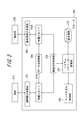
- FIG. 1 is a functional block diagram showing a schematic configuration of a base station constituting a radio communication system according to an embodiment of the present invention.
- Each base station communicates with a mobile station (terminal) by FDD.
- the base station 100 communicates with other base stations 108 and the EMS 109 in the wireless communication system via the network interface (IF) unit 105.
- the EMS 109 is installed, for example, in a management center that manages the wireless communication system, and includes a system parameter determination unit 113 described later, and monitors and operates the entire system.
- the base station 100 includes a wireless reception unit 101 and a wireless transmission unit 102 that communicate with a terminal or a relay device such as a repeater.
- the radio unit 103 converts the radio signal having the reception frequency received by the radio reception unit 101 into data. Further, the wireless unit 103 converts data transmitted by the wireless transmission unit 102 into a wireless signal having a transmission frequency.
- the wireless characteristic control unit 104 controls the transmission output of the wireless unit 103. This control is performed based on parameters that the system parameter management unit 107 incorporating the storage unit 110 acquires and manages from the EMS 109 via the network IF unit 105.
- the wireless signal transmission output is the minimum transmission output capable of maintaining communication with the repeater connected to itself.
- the data transmission / reception unit 106 transmits data acquired by communicating with another base station 108 or EMS 109 via the network IF unit 105 to the wireless unit 103.
- the base station 100 further includes a setting information holding unit 111 that stores setting information necessary for communication such as an IP address, and a GPS position measuring unit 112 that acquires position information of the own station.
- Other base stations 108 have the same configuration as base station 100.
- FIG. 2 is a functional block diagram showing a schematic configuration of a repeater that is a relay device constituting the wireless communication system according to the embodiment of the present invention.
- the repeater 200 includes a terminal-side transmission / reception unit 201 that transmits / receives data to / from the terminal 211, and a configuration similar to that of the base station 100 and the base station 108 described above.
- the base station side transmission / reception unit 202 performs transmission / reception.
- the repeater 200 relays the data received from the terminal 211 to the base station 208, the repeater 200 processes the data received by the terminal side transmitting / receiving unit 201 by the wireless unit 203A, and via the data transmitting / receiving unit 206, Send to the wireless unit 203B.
- the wireless unit 203B processes the received data into, for example, an uplink frequency signal. Then, the base station side transmitting / receiving unit 202 transmits the data processed by the wireless unit 203B to the base station 208. When the repeater 200 relays the data received from the base station 208 to the terminal 211, the data received by the base station side transmitting / receiving unit 202 is transmitted via the wireless unit 203B, the data transmitting / receiving unit 206, and the wireless unit 203A. The data is transmitted from the terminal side transceiver 201 to the terminal 211.
- the system parameter management unit 207 causes the radio characteristic control unit 204 (second control unit) to control the radio units 203A and 203B and controls the antenna direction control unit 205 based on the managed system parameters.
- the antenna direction control unit 205 controls the antenna by, for example, tilting and beam forming.
- the storage unit 210 stores system parameters received via the base station side transmitting / receiving unit 202 and the wireless unit 203B. This system parameter is set in the EMS 109 and transmitted from the base station 208 which is a master station.
- the wireless characteristic control unit 204 controls the transmission output of the wireless units 203A and 203B according to the system parameters managed by the system parameter management unit 207.
- the system parameter relating to the transmission output corresponds to the value determined by the system parameter determination unit 113 of the EMS 109. Further, when the base station side transmitting / receiving unit 202 receives a predetermined radio signal, the radio characteristic control unit 204 transmits a signal indicating the detection to the connected base station.
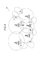
- the wireless communication system is configured with a communication area 300 as shown in FIG. 3 to 6 have the same configuration as the base stations 100, 108, and 208 described above, and the repeaters 1 to 7 have the same configuration as the repeater 200 described above.
- circles centered on base stations A to D each represent a cell of each base station. Repeaters 1 to 7 having the base stations A to D as parent stations are arranged, and the communication area 300 is expanded.
- repeater 4 is arranged for base station A, repeaters 2 and 5 for base station B, repeaters 1 and 6 for base station C, and repeaters 3 and 7 for base station D. It shall be.
- an area 301 that does not belong to any of the cells of the base stations B, C, and D is an area where communication can be performed by the repeaters 1 to 3.
- each base station A to D holds information about handover candidate base stations, and holds IP address information of those base stations.
- the base station C holds the IP address information of adjacent base stations A, B and D as handover candidate information.
- each of the base stations A to D is communicating with, for example, terminals exceeding 80% of the maximum terminal capacity of the own station. Under such circumstances, if a transport body with a large number of communication terminals such as buses and trains in passenger transportation enters the communication area 300 shown in FIG. 3, there is a risk of congestion in communication in the communication area 300. There is. Therefore, in the present embodiment, it is assumed that one base station E is newly installed in the area 301 in which communication is possible by the repeaters 1 to 3.
- the base station E uses a control channel (Control Channel: CCH) under the control of the radio characteristic control unit 104 to start with a low transmission output and gradually increase the transmission output.
- a radio signal predetermined radio signal
- the repeaters 1 to 3 installed around the base station E can supplement the control channel signals of the base station E, respectively.
- the existing base stations B to D around the base station E gradually decrease the transmission output. As a result, as shown in FIG. 4, the cells of the base stations B and D become smaller than the time of FIG. 3, and the possibility of interference with the base station E is reduced.
- the dashed arrow in FIG. 5 indicates wireless communication
- the solid arrow indicates, in principle, wired communication.
- an IP address is automatically assigned from the network by, for example, DHCP (Dynamic Host Configuration Protocol).
- the base station E automatically acquires the position information of the base station by the GPS position measurement unit 112 at the same time as being installed. Then, the base station E reports to the EMS 109 the assigned IP address and the acquired location information. Accordingly, the system parameter determination unit 113 of the EMS 109 grasps the positional relationship between the base station E and the existing base stations and repeaters installed around the base station E, and configures the area configuration around the base station E. To grasp.
- the base station E After notifying the EMS 109 of the location information and IP address of the own station, the base station E transmits a radio signal by CCH by the radio transmission unit 102 while gradually increasing the transmission output.
- the base station E increases the transmission power stepwise or continuously.
- the repeater 2 having the shortest distance to the base station E has received the signal transmitted from the base station E at the earliest time among the repeaters around the base station E.
- the repeater 2 receives the radio signal transmitted from the base station E by the base station side transmitting / receiving unit 202, the repeater 2 notifies the base station B, which is the master station, of the fact.
- the repeater 2 notifies the base station B not only of the reception of the radio signal from the base station E but also the information of the reception time.
- the reception time information is then notified to the base station E, and the base station E grasps the reception time information in association with the transmission output at that time.
- the base station B Upon receiving the notification, the base station B notifies the EMS 109 via the network IF unit 105 that the repeater 2 has received the signal from the base station E, and gradually starts to lower its own transmission output. While the base station B communicates with the repeater 5 having the base station B as a parent station, the wireless characteristic control unit 104 controls the wireless unit 103 to a minimum transmission output capable of maintaining communication with the repeater 5. Decrease transmission output gradually. When the minimum value of the transmission output is determined, the base station B notifies the EMS 109 of the determined minimum value of the transmission output. In addition, although not shown in FIG.
- the base station D also outputs a transmission output up to a minimum value that can maintain communication with the repeater 7 that has its own station as a parent station and does not receive a signal from the base station E. Decrease and notify EMS 109 of the minimum value.
- the EMS 109 notifies the base station E to determine the transmission output value, and notifies the signal reception time information from the base station E in the repeater 2.
- the base station E sets its own transmission output based on the transmission output at this signal reception time so that the repeater 2 can stably communicate with the base station E. For example, when the transmission output increases stepwise, the base station E sets the signal output value one to several steps after the signal reception time, and when the increase in transmission output is linear, the base station E The station E sets the transmission output value after a predetermined time from the signal reception time.
- the base station E sets an output that is slightly larger than the transmission output at the signal reception time, for example, an output value that is 10 to 20% larger than the reference transmission output value as the transmission output of its own station. Then, the base station E notifies the EMS 109 of the set transmission output value.
- the repeater 2 notifies each of the base stations B and E of the reception level of the signal from each base station.
- Each of the base stations B and E reports the reception level at the repeater 2 to the EMS 109.
- the system parameter determination unit 113 of the EMS 109 compares the reception levels and determines that the base station with the higher reception level is newly set as the parent station of the repeater 2. In the communication area 400 shown in FIG. 4, if the signal reception level at the repeater 2 is higher in the signal from the base station E than the signal from the base station B, the EMS 109 moves the parent station of the repeater 2 from the base station B. Decide to change to base station E.
- the EMS 109 compares the reception levels of the signals transmitted from the base station D and the base station E received by the repeater 3, and determines the parent station of the repeater 3 from the base station D to the base station E. Decide to change to. Then, the EMS 109 notifies the base station B of a system parameter including information indicating that the parent station of the repeater 2 is changed, and notifies the base station D of a system parameter including information indicating that the parent station of the repeater 3 is changed. . Receiving the notification from the EMS 109, the base stations B and D store the information in the setting information holding unit 111 by the system parameter management unit 107.
- the EMS 109 determines the positional relationship with the existing base stations A to D based on the positional information and IP address acquired from the base station E. Then, the base stations B to D, which are peripheral stations of the newly established base station E, are notified to additionally register the ID of the base station E in the handover destination candidate station. Upon receiving the notification, the base stations B to D additionally register the ID of the base station E as a handover destination candidate station in the setting information holding unit 111. Also, the EMS 109 notifies the base station E to register the IDs of the base stations B to D as handover destination candidate stations.
- the system parameter determination unit 113 of the EMS 109 confirms that the base stations A and E are geographically close but the cells do not overlap with each other based on the grasped positional relationship between the base stations A and E and the cell size.
- the base station E is notified to register the ID of the base station A as a non-handover destination. Receiving the notification, the base station E registers that in the setting information holding unit 111.
- the EMS 109 receives the beams of the repeaters 1 to 7 arranged in the area in order to further optimize the area configuration based on the position information of each base station and each repeater, the transmission output of each base station, and the like. Forming and tilting parameters, that is, parameters for adjusting the antenna direction are generated. Then, the EMS 109 transmits the generated parameter via the base station E to the system parameter management unit 207 in each of the repeaters 2 and 3 that newly set the base station E as the parent station.
- the antenna direction control unit 205 of the repeaters 2 and 3 controls the antenna direction according to the parameters received by the system parameter management unit 207, and adjusts beam forming and tilting as shown in FIG. Thereby, stable system operation is possible. In addition, as shown in FIG.
- the repeater 1 having the base station C as a parent station also has, for example, an antenna direction so as not to interfere with the base station E based on parameters sent from the EMS 109 via the base station C. To control the transmission output. Thereby, power consumption can be reduced.
- the repeater receives a signal transmitted from the newly installed base station and notifies the existing base station to that effect.
- the information of the signal transmitted from the newly installed base station to the existing base station can be obtained stably without increasing the cost for the base station itself.
- the system parameter is determined in the EMS, but such determination may be implemented in the base station apparatus itself.
- the transmission output value of the base station E is determined based on the signal output value at the time when the repeater 2 closest to the newly established base station E receives the signal from the base station E.
- the EMS can determine the transmission output value of the base station E using reception times at a plurality of repeaters. At this time, the EMS may calculate the transmission output based on weighting or statistical processing.
Abstract
Description
ネットワークを介して接続する複数の基地局と、該複数の基地局のいずれか一つと移動局との通信を中継する1又は複数の中継装置と、を含む無線通信システムのパラメータ調整方法であって、
新規に設置された新規基地局が、
送信出力を増加させながら、無線信号を送信するステップと、
前記中継装置が、
前記新規基地局からの無線信号を検出した場合に、接続中の既存基地局に、該無線信号の検出を示す信号を送信するステップと、
前記既存基地局が、
前記検出を示す信号を受信すると、当該既存基地局の無線信号の送信出力を、当該既存基地局に接続する一又は複数の中継装置との通信が維持可能な最小送信出力まで低下させるステップと、
前記最小送信出力を当該既存基地局の送信出力とする様に、当該既存基地局の送信出力のパラメータを調整するステップと、
前記新規基地局が、
前記ネットワークを介して前記中継装置における当該新規基地局からの無線信号の検出時に関する情報を取得し、当該時点における当該新規基地局の送信出力に基づいて、当該新規基地局の送信出力のパラメータを設定するステップと、
を有することを特徴とするものである。 The invention of the parameter adjustment method according to the first aspect of achieving the above object,
A parameter adjustment method for a wireless communication system, comprising: a plurality of base stations connected via a network; and one or a plurality of relay apparatuses that relay communication between any one of the plurality of base stations and a mobile station. ,
A newly installed base station
Transmitting a radio signal while increasing transmission power;
The relay device is
When a radio signal from the new base station is detected, transmitting a signal indicating the detection of the radio signal to the existing base station being connected;
The existing base station is
When receiving a signal indicating the detection, reducing the transmission output of the radio signal of the existing base station to a minimum transmission output capable of maintaining communication with one or more relay devices connected to the existing base station;
Adjusting the parameter of the transmission power of the existing base station so that the minimum transmission power is the transmission power of the existing base station;
The new base station is
Obtain information about the time of detection of a radio signal from the new base station in the relay device via the network, and based on the transmission output of the new base station at the time point, the parameter of the transmission output of the new base station Steps to set,
It is characterized by having.
前記一又は複数の中継装置が、前記複数の基地局のそれぞれからの送信出力に基づいて、接続先の基地局を選択するステップをさらに有することを特徴とするものである。 The invention according to the second aspect is a parameter adjustment method according to the first aspect,
The one or more relay apparatuses further include a step of selecting a connection destination base station based on transmission outputs from each of the plurality of base stations.
前記一又は複数の中継装置がアンテナの方向を制御するアンテナ方向制御部を有しており、当該中継装置が前記接続先の基地局に応じて前記アンテナの方向を制御するステップをさらに有することを特徴とするものである。 The invention according to a third aspect is a parameter adjustment method according to the second aspect,
The one or more relay apparatuses have an antenna direction control unit that controls the direction of the antenna, and the relay apparatus further includes a step of controlling the direction of the antenna according to the base station of the connection destination. It is a feature.
ネットワークを介して接続する複数の基地局と、該複数の基地局のいずれか一つと移動局との通信を中継する1又は複数の中継装置と、を含む無線通信システムであって、
前記基地局は、
無線信号を送受信する第1送受信部と、
無線信号を送信する際の送信出力のパラメータを管理する管理部と、
前記送信出力を制御する第1制御部と、を備え、
前記中継装置は、
前記基地局との無線信号を送受信する第2送受信部と、
所定の無線信号が前記第2送受信部で受信されると、接続中の前記基地局に、当該所定の無線信号の検出を示す信号を送信する第2制御部と、を備え、
前記基地局は、
新規に設置された新規基地局である場合には、前記第1制御部の制御により前記第1送受信部から送信出力を増加させながら前記所定の無線信号を送信し、前記管理部は、前記ネットワークを介して前記中継装置における前記所定の無線信号の検出時に関する情報を取得し、当該時点における送信出力に基づいて、送信出力のパラメータを設定し、
既に設置されている既存基地局である場合には、前記検出を示す信号を受信すると、前記第1制御部は、無線信号の送信出力を、当該既存基地局に接続する一又は複数の中継装置との通信が維持可能な最小送信出力まで低下させ、前記管理部は、当該最小送信出力を送信出力とする様に、送信出力のパラメータを調整する、
ことを特徴とするものである。 The invention of the wireless communication system according to the fourth aspect of achieving the above object is as follows:
A wireless communication system including a plurality of base stations connected via a network, and one or a plurality of relay devices that relay communication between any one of the plurality of base stations and a mobile station,
The base station
A first transmission / reception unit for transmitting / receiving a radio signal;
A management unit for managing parameters of transmission output when transmitting a radio signal;
A first control unit for controlling the transmission output,
The relay device is
A second transceiver for transmitting and receiving radio signals to and from the base station;
A second control unit configured to transmit a signal indicating detection of the predetermined radio signal to the connected base station when a predetermined radio signal is received by the second transmission / reception unit;
The base station
In the case of a newly installed new base station, the predetermined radio signal is transmitted while increasing the transmission output from the first transmission / reception unit under the control of the first control unit, and the management unit To obtain information on the detection time of the predetermined radio signal in the relay device, based on the transmission output at the time, set the parameter of the transmission output,
In the case of an existing base station that is already installed, upon receiving the signal indicating the detection, the first control unit connects one or more relay devices that connect the transmission output of the radio signal to the existing base station And the management unit adjusts the parameter of the transmission output so that the minimum transmission output is the transmission output.
It is characterized by this.
101 無線受信部
102 無線送信部
103 無線ユニット
104 無線特性制御部
105 ネットワークIF部
106、206 データ送受信部
107、207 システムパラメータ管理部
108、208 基地局
109 EMS
110、210 記憶部
111 設定情報保持部
112 GPS位置測定部
113 システムパラメータ判定部
200 リピータ
201 端末側送受信部
202 基地局側送受信部
203A、203B 無線ユニット
204 無線特性制御部
205 アンテナ方向制御部
211 端末
300、400、500 通信エリア
301 領域 DESCRIPTION OF
DESCRIPTION OF SYMBOLS 110,210
Claims (4)
- ネットワークを介して接続する複数の基地局と、該複数の基地局のいずれか一つと移動局との通信を中継する1又は複数の中継装置と、を含む無線通信システムのパラメータ調整方法であって、
新規に設置された新規基地局が、
送信出力を増加させながら、無線信号を送信するステップと、
前記中継装置が、
前記新規基地局からの無線信号を検出した場合に、接続中の既存基地局に、該無線信号の検出を示す信号を送信するステップと、
前記既存基地局が、
前記検出を示す信号を受信すると、当該既存基地局の無線信号の送信出力を、当該既存基地局に接続する一又は複数の中継装置との通信が維持可能な最小送信出力まで低下させるステップと、
前記最小送信出力を当該既存基地局の送信出力とする様に、当該既存基地局の送信出力のパラメータを調整するステップと、
前記新規基地局が、
前記ネットワークを介して前記中継装置における当該新規基地局からの無線信号の検出時に関する情報を取得し、当該時点における当該新規基地局の送信出力に基づいて、当該新規基地局の送信出力のパラメータを設定するステップと、
を有することを特徴とするパラメータ調整方法。 A parameter adjustment method for a wireless communication system, comprising: a plurality of base stations connected via a network; and one or a plurality of relay apparatuses that relay communication between any one of the plurality of base stations and a mobile station. ,
A newly installed base station
Transmitting a radio signal while increasing transmission power;
The relay device is
When a radio signal from the new base station is detected, transmitting a signal indicating the detection of the radio signal to the existing base station being connected;
The existing base station is
When receiving a signal indicating the detection, reducing the transmission output of the radio signal of the existing base station to a minimum transmission output capable of maintaining communication with one or more relay devices connected to the existing base station;
Adjusting the parameter of the transmission power of the existing base station so that the minimum transmission power is the transmission power of the existing base station;
The new base station is
Obtain information about the time of detection of a radio signal from the new base station in the relay device via the network, and based on the transmission output of the new base station at the time point, the parameter of the transmission output of the new base station Steps to set,
A parameter adjustment method characterized by comprising: - 前記一又は複数の中継装置が、前記複数の基地局のそれぞれからの送信出力に基づいて、接続先の基地局を選択するステップをさらに有することを特徴とする請求項1に記載の方法。 The method according to claim 1, further comprising the step of the one or more relay apparatuses selecting a connection destination base station based on a transmission output from each of the plurality of base stations.
- 前記一又は複数の中継装置がアンテナの方向を制御するアンテナ方向制御部を有しており、当該中継装置が前記接続先の基地局に応じて前記アンテナの方向を制御するステップをさらに有することを特徴とする請求項2に記載の方法。 The one or more relay apparatuses have an antenna direction control unit that controls the direction of the antenna, and the relay apparatus further includes a step of controlling the direction of the antenna according to the base station of the connection destination. The method of claim 2, wherein the method is characterized in that:
- ネットワークを介して接続する複数の基地局と、該複数の基地局のいずれか一つと移動局との通信を中継する1又は複数の中継装置と、を含む無線通信システムであって、
前記基地局は、
無線信号を送受信する第1送受信部と、
無線信号を送信する際の送信出力のパラメータを管理する管理部と、
前記送信出力を制御する第1制御部と、を備え、
前記中継装置は、
前記基地局との無線信号を送受信する第2送受信部と、
所定の無線信号が前記第2送受信部で受信されると、接続中の前記基地局に、当該所定の無線信号の検出を示す信号を送信する第2制御部と、を備え、
前記基地局は、
新規に設置された新規基地局である場合には、前記第1制御部の制御により前記第1送受信部から送信出力を増加させながら前記所定の無線信号を送信し、前記管理部は、前記ネットワークを介して前記中継装置における前記所定の無線信号の検出時に関する情報を取得し、当該時点における送信出力に基づいて、送信出力のパラメータを設定し、
既に設置されている既存基地局である場合には、前記検出を示す信号を受信すると、前記第1制御部は、無線信号の送信出力を、当該既存基地局に接続する一又は複数の中継装置との通信が維持可能な最小送信出力まで低下させ、前記管理部は、当該最小送信出力を送信出力とする様に、送信出力のパラメータを調整する、
ことを特徴とする無線通信システム。 A wireless communication system including a plurality of base stations connected via a network, and one or a plurality of relay devices that relay communication between any one of the plurality of base stations and a mobile station,
The base station
A first transmission / reception unit for transmitting / receiving a radio signal;
A management unit for managing parameters of transmission output when transmitting a radio signal;
A first control unit for controlling the transmission output,
The relay device is
A second transceiver for transmitting and receiving radio signals to and from the base station;
A second control unit configured to transmit a signal indicating detection of the predetermined radio signal to the connected base station when a predetermined radio signal is received by the second transmission / reception unit;
The base station
In the case of a newly installed new base station, the predetermined radio signal is transmitted while increasing the transmission output from the first transmission / reception unit under the control of the first control unit, and the management unit To obtain information on the detection time of the predetermined radio signal in the relay device, based on the transmission output at the time, set the parameter of the transmission output,
In the case of an existing base station that is already installed, upon receiving the signal indicating the detection, the first control unit connects one or more relay devices that connect the transmission output of the radio signal to the existing base station And the management unit adjusts the parameter of the transmission output so that the minimum transmission output is the transmission output.
A wireless communication system.
Priority Applications (2)
| Application Number | Priority Date | Filing Date | Title |
|---|---|---|---|
| CN2011800212974A CN102860057A (en) | 2010-04-26 | 2011-04-25 | Wireless communication system parameter adjusting method and wireless communication system |
| US13/641,683 US8989796B2 (en) | 2010-04-26 | 2011-04-25 | Method for adjusting parameter of radio communication system and radio communication system |
Applications Claiming Priority (2)
| Application Number | Priority Date | Filing Date | Title |
|---|---|---|---|
| JP2010101434A JP5457929B2 (en) | 2010-04-26 | 2010-04-26 | Parameter adjustment method for wireless communication system and wireless communication system |
| JP2010-101434 | 2010-04-26 |
Publications (1)
| Publication Number | Publication Date |
|---|---|
| WO2011135842A1 true WO2011135842A1 (en) | 2011-11-03 |
Family
ID=44861164
Family Applications (1)
| Application Number | Title | Priority Date | Filing Date |
|---|---|---|---|
| PCT/JP2011/002428 WO2011135842A1 (en) | 2010-04-26 | 2011-04-25 | Wireless communication system parameter adjusting method and wireless communication system |
Country Status (4)
| Country | Link |
|---|---|
| US (1) | US8989796B2 (en) |
| JP (1) | JP5457929B2 (en) |
| CN (1) | CN102860057A (en) |
| WO (1) | WO2011135842A1 (en) |
Cited By (2)
| Publication number | Priority date | Publication date | Assignee | Title |
|---|---|---|---|---|
| CN103458474A (en) * | 2012-06-04 | 2013-12-18 | 中兴通讯股份有限公司 | Method and device for managing multiple self-organizing networks |
| CN103957585A (en) * | 2014-04-22 | 2014-07-30 | 福建三元达通讯股份有限公司 | Power control method and device for wireless local area network access point device |
Families Citing this family (11)
| Publication number | Priority date | Publication date | Assignee | Title |
|---|---|---|---|---|
| JP5772345B2 (en) * | 2011-07-25 | 2015-09-02 | 富士通株式会社 | Parameter setting apparatus, computer program, and parameter setting method |
| JP6208409B2 (en) | 2012-04-06 | 2017-10-04 | 株式会社Nttドコモ | User device and communication method |
| KR20140072968A (en) * | 2012-12-05 | 2014-06-16 | 한국전자통신연구원 | Method for terminal handover using multi-connection in cellular telecommunication system |
| CN107404723B (en) | 2016-05-20 | 2020-08-21 | 北京小米移动软件有限公司 | Method and device for accessing base station |
| JP6606469B2 (en) * | 2016-06-13 | 2019-11-13 | 株式会社日立製作所 | Communication system and wireless network engineering support method |
| KR101883995B1 (en) * | 2017-06-23 | 2018-07-31 | 주식회사 케이티 | System and method for PCI allocation and PCI collision detection of femto-cell method using the same |
| US11070806B2 (en) * | 2017-06-28 | 2021-07-20 | Lg Electronics Inc. | Method and apparatus for performing low complexity computation in transform kernel for video compression |
| CN113395722B (en) * | 2021-06-10 | 2022-06-07 | 中国民用航空华北地区空中交通管理局内蒙古分局 | Method and device for open field test and automatic interference detection of civil aviation radio station |
| CN113727373B (en) * | 2021-08-26 | 2024-01-23 | 深圳国人无线通信有限公司 | Parameter self-configuration method comprising repeater network system |
| WO2023087240A1 (en) * | 2021-11-19 | 2023-05-25 | Zte Corporation | Methods, devices, and systems for transmitting and receiving signal for power management |
| WO2023166711A1 (en) * | 2022-03-04 | 2023-09-07 | 三菱電機株式会社 | Parameter automatic adjusting apparatus, control circuit, storage medium, and parameter automatic adjusting method |
Citations (2)
| Publication number | Priority date | Publication date | Assignee | Title |
|---|---|---|---|---|
| JP2007532079A (en) * | 2004-04-05 | 2007-11-08 | クゥアルコム・インコーポレイテッド | A repeater that reports detected neighbors |
| JP2008172380A (en) * | 2007-01-09 | 2008-07-24 | Ntt Docomo Inc | Base station device used for mobile communication system, and user device and method |
Family Cites Families (6)
| Publication number | Priority date | Publication date | Assignee | Title |
|---|---|---|---|---|
| FI116819B (en) | 2000-01-21 | 2006-02-28 | Nokia Corp | Procedure for transferring images and an image encoder |
| WO2005125249A1 (en) | 2004-06-18 | 2005-12-29 | Mitsubishi Denki Kabushiki Kaisha | Autonomous cell formation method |
| KR100750128B1 (en) | 2005-09-06 | 2007-08-21 | 삼성전자주식회사 | Method and apparatus for intra prediction of video |
| CN101192874A (en) * | 2006-11-22 | 2008-06-04 | 北京三星通信技术研究有限公司 | Self-adapted routing information broadcast and routing method in relay system |
| JP4568750B2 (en) | 2007-11-30 | 2010-10-27 | 富士通株式会社 | Drawing apparatus, drawing program, and drawing method |
| EP2081386A1 (en) | 2008-01-18 | 2009-07-22 | Panasonic Corporation | High precision edge prediction for intracoding |
-
2010
- 2010-04-26 JP JP2010101434A patent/JP5457929B2/en not_active Expired - Fee Related
-
2011
- 2011-04-25 WO PCT/JP2011/002428 patent/WO2011135842A1/en active Application Filing
- 2011-04-25 CN CN2011800212974A patent/CN102860057A/en active Pending
- 2011-04-25 US US13/641,683 patent/US8989796B2/en not_active Expired - Fee Related
Patent Citations (2)
| Publication number | Priority date | Publication date | Assignee | Title |
|---|---|---|---|---|
| JP2007532079A (en) * | 2004-04-05 | 2007-11-08 | クゥアルコム・インコーポレイテッド | A repeater that reports detected neighbors |
| JP2008172380A (en) * | 2007-01-09 | 2008-07-24 | Ntt Docomo Inc | Base station device used for mobile communication system, and user device and method |
Cited By (4)
| Publication number | Priority date | Publication date | Assignee | Title |
|---|---|---|---|---|
| CN103458474A (en) * | 2012-06-04 | 2013-12-18 | 中兴通讯股份有限公司 | Method and device for managing multiple self-organizing networks |
| CN103458474B (en) * | 2012-06-04 | 2018-01-30 | 中兴通讯股份有限公司 | More self-organized network management method and apparatus |
| CN103957585A (en) * | 2014-04-22 | 2014-07-30 | 福建三元达通讯股份有限公司 | Power control method and device for wireless local area network access point device |
| CN103957585B (en) * | 2014-04-22 | 2017-12-08 | 福建三元达网络技术有限公司 | The Poewr control method and device of a kind of device of wireless local area network access point |
Also Published As
| Publication number | Publication date |
|---|---|
| US20130065516A1 (en) | 2013-03-14 |
| CN102860057A (en) | 2013-01-02 |
| JP2011234052A (en) | 2011-11-17 |
| US8989796B2 (en) | 2015-03-24 |
| JP5457929B2 (en) | 2014-04-02 |
Similar Documents
| Publication | Publication Date | Title |
|---|---|---|
| JP5457929B2 (en) | Parameter adjustment method for wireless communication system and wireless communication system | |
| US10028308B2 (en) | Mobile communication system, user terminal, processor, and base station | |
| EP3158692B1 (en) | Systems and methods for selecting an optimum communication route in a wireless network | |
| US11212711B2 (en) | Uplink interference-based monitoring of downlink signals by unmanned aerial vehicle | |
| JP5260251B2 (en) | Use frequency band adjustment method and radio communication apparatus in cognitive radio system | |
| KR101828876B1 (en) | Radio communication method, radio communication system, radio base station, and radio terminal | |
| US7912010B2 (en) | Wireless connection terminal and roaming method for providing stable wireless connection to access point | |
| US9161307B2 (en) | Upper-layer base station, lower-layer base station and wireless communication system | |
| WO2010024206A1 (en) | Relay station, and base station | |
| US11025329B2 (en) | Communication apparatus, communication control method, and computer program | |
| KR20220124213A (en) | Relay device for wireless communication system | |
| JP2021093761A (en) | Method for connection establishment using common random access preamble | |
| US20140219122A1 (en) | Control apparatus, representative base station and base station control method | |
| EP3169115B1 (en) | Micro cell base station and method and system for adjusting transmit power of micro cell base station | |
| WO2019023502A1 (en) | Methods and systems for channel switching in a wireless communication system | |
| EP2942986A1 (en) | Low complexity user equipment and their operation within wireless communication networks | |
| US9119177B2 (en) | Radio base station and method for selecting frequency band of radio base station | |
| JP2012023598A (en) | Wireless communication system, relay device, control device and communication method | |
| WO2017086046A1 (en) | Communication terminal | |
| JP6773968B2 (en) | Multi-site trunking system and site switching method | |
| JP5172933B2 (en) | Wireless base station system, wireless control device, wireless terminal, and radio wave state map creation method | |
| CN114175516B (en) | Electronic device and method in wireless communication system | |
| CN114631392A (en) | Method and apparatus for switching data transmission between radio access technologies for early data transmission | |
| JP2013207563A (en) | Radio communication system, base station, mobile station, and radio communication method | |
| TW202110209A (en) | Method and apparatus for setting up and/or adjusting backhaul link in maritime network |
Legal Events
| Date | Code | Title | Description |
|---|---|---|---|
| WWE | Wipo information: entry into national phase |
Ref document number: 201180021297.4 Country of ref document: CN |
|
| 121 | Ep: the epo has been informed by wipo that ep was designated in this application |
Ref document number: 11774628 Country of ref document: EP Kind code of ref document: A1 |
|
| WWE | Wipo information: entry into national phase |
Ref document number: 13641683 Country of ref document: US |
|
| NENP | Non-entry into the national phase |
Ref country code: DE |
|
| 122 | Ep: pct application non-entry in european phase |
Ref document number: 11774628 Country of ref document: EP Kind code of ref document: A1 |