WO2011133652A2 - Multi-rotor flow control valve - Google Patents
Multi-rotor flow control valve Download PDFInfo
- Publication number
- WO2011133652A2 WO2011133652A2 PCT/US2011/033222 US2011033222W WO2011133652A2 WO 2011133652 A2 WO2011133652 A2 WO 2011133652A2 US 2011033222 W US2011033222 W US 2011033222W WO 2011133652 A2 WO2011133652 A2 WO 2011133652A2
- Authority
- WO
- WIPO (PCT)
- Prior art keywords
- flow
- area
- rotor
- stator
- total
- Prior art date
- Legal status (The legal status is an assumption and is not a legal conclusion. Google has not performed a legal analysis and makes no representation as to the accuracy of the status listed.)
- Ceased
Links
Classifications
-
- F—MECHANICAL ENGINEERING; LIGHTING; HEATING; WEAPONS; BLASTING
- F16—ENGINEERING ELEMENTS AND UNITS; GENERAL MEASURES FOR PRODUCING AND MAINTAINING EFFECTIVE FUNCTIONING OF MACHINES OR INSTALLATIONS; THERMAL INSULATION IN GENERAL
- F16K—VALVES; TAPS; COCKS; ACTUATING-FLOATS; DEVICES FOR VENTING OR AERATING
- F16K3/00—Gate valves or sliding valves, i.e. cut-off apparatus with closing members having a sliding movement along the seat for opening and closing
- F16K3/02—Gate valves or sliding valves, i.e. cut-off apparatus with closing members having a sliding movement along the seat for opening and closing with flat sealing faces; Packings therefor
- F16K3/04—Gate valves or sliding valves, i.e. cut-off apparatus with closing members having a sliding movement along the seat for opening and closing with flat sealing faces; Packings therefor with pivoted closure members
- F16K3/06—Gate valves or sliding valves, i.e. cut-off apparatus with closing members having a sliding movement along the seat for opening and closing with flat sealing faces; Packings therefor with pivoted closure members in the form of closure plates arranged between supply and discharge passages
- F16K3/08—Gate valves or sliding valves, i.e. cut-off apparatus with closing members having a sliding movement along the seat for opening and closing with flat sealing faces; Packings therefor with pivoted closure members in the form of closure plates arranged between supply and discharge passages with circular plates rotatable around their centres
- F16K3/085—Gate valves or sliding valves, i.e. cut-off apparatus with closing members having a sliding movement along the seat for opening and closing with flat sealing faces; Packings therefor with pivoted closure members in the form of closure plates arranged between supply and discharge passages with circular plates rotatable around their centres the axis of supply passage and the axis of discharge passage being coaxial and parallel to the axis of rotation of the plates
-
- Y—GENERAL TAGGING OF NEW TECHNOLOGICAL DEVELOPMENTS; GENERAL TAGGING OF CROSS-SECTIONAL TECHNOLOGIES SPANNING OVER SEVERAL SECTIONS OF THE IPC; TECHNICAL SUBJECTS COVERED BY FORMER USPC CROSS-REFERENCE ART COLLECTIONS [XRACs] AND DIGESTS
- Y10—TECHNICAL SUBJECTS COVERED BY FORMER USPC
- Y10T—TECHNICAL SUBJECTS COVERED BY FORMER US CLASSIFICATION
- Y10T29/00—Metal working
- Y10T29/49—Method of mechanical manufacture
- Y10T29/49405—Valve or choke making
Definitions
- the technical field generally relates to flow control valves in engine related gaseous streams.
- Presently available flow control valves suffer from highly constrained trade-offs between flow capacity and controllability.
- Butter fly and poppet valves have very good flow capacity but they have a highly non-linear flow response making controllability difficult.
- Butter fly and poppet valves also require relatively large actuator torque to control the valve.
- Rotary valves have improved controllability with a more linear flow response, but also have drawbacks.
- Rotary valves have limited available flow area and therefore a reduced flow capacity, and further many commercially available rotary valves include a 90° turn within the valve or on exit of the valve, thereby increasing pressure drop and further reducing flow capacity. Therefore, further technological developments are desirable in this area.
- One embodiment is a unique article of manufacture including a high capacity, highly responsive rotary valve. Further embodiments, forms, objects, features, advantages, aspects, and benefiis shall become apparent from the following description and drawings.
- Fig. 1 is a schematic diagram of a system including a high capacity rotary valve.
- Fig. 2a is a schematic diagram of a high capacity rotary valve at first open position.
- Fig. 2b is a schematic diagram of the high capacity rotary valve at an intermediate position.
- Fig. 2c is a schematic diagram of the high capacity rotary valve at a second position.
- Fig. 3 is a schematic diagram of a high capacity rotary valve separated to illustrate an engagement gear and ridged arc members.
- Fig. 4 is an exploded schematic illustration of a high capacity rotary valve.
- Fig. 5a is a schematic diagram of a first rotor and a second rotor in a first position.
- Fig. 5b is a schematic diagram, of the first rotor and the second rotor in a second position.
- Fig. 5c is a schematic diagram of an isometric view of the first rotor and the second rotor in the second position.
- Fig. 1 is a schematic diagram of a system ] 00 including a high capacity rotary valve 106.
- the system 100 includes an internal combustion engine 102 having a gaseous flow stream 104 and the rotary valve 106 disposed in the gaseous flow stream 104.
- the system 100 may further include an intercooler 122, an EGR cooler 120, and/or an aftertreatment component 1 18.
- the exemplary system 100 further includes a compressor 124 and a turbine 126.
- the compressor 124 and turbine 126 are shown separately in Fig. 1 to more clearly show the operational connections of various streams, but the compressor 124 and turbine 126 are typically positioned together in a turbocharger device connected by a shaft.
- the gaseous flow stream 104 may be an exhaust gas recirculation (EGR) 104 as shown, but the gaseous flow stream 104 may be any engine-related stream known in the art.
- Non-limiting exemplary gaseous flow streams include an EGR cooler bypass 108, a turbine bypass 110, a compressor bypass 1 12, an intercooler bypass 114, and/or an aftertreatment component bypass 1 16.
- the routes and connections of the various bypass streams are exemplary and non-limiting.
- the system 100 may include multiple rotary valves 106 although only one is shown for clarity.
- Fig. 2a is a schematic diagram of a high capacity rotary valve 106.
- the rotary valve 106 includes a first rotor 204 (reference Fig. 2b) and a second rotor 202.
- the rotors 202, 204 are at at a second position, or an open position, having a maximum flow-through area 208.
- the rotary valve 106 includes a stator 206 coupled to the rotors, the stator having a flow-through area including the maximum flow- through area 208.
- the maximum flow-through area 208 represents the greatest available f!ow-through area available from the orifices, slots, or other openings in the stator 206, as limited by structural, or other considerations. For example, pins, bolts, screws, or other devices may attach to or pass through the stator 206, and a portion of the rotors 202, 204 may not rotate completely out of the path of the stator 206 openings.
- the first rotor 202 and the second rotor 204 rotate simultaneously and in opposite directions.
- a single actuator 210 moves both the first rotor 202 and the second rotor 204.
- the rotation of the rotors 202, 204 in simultaneous, opposite directions allows for rapid response of the rotary valve 206 to a position command, and further enables ease of actuating both rotors 202, 204 from a single actuator.
- the rotors 202, 204 may move in the same direction, serially, be independently operable, or actuated in any manner known in the art.
- Fig. 2c illustrates the rotors 202, 204 in a first position that closes the gaseous flow stream.
- the rotors 202, 204 in Fig. 2c co-ordinate to cover the maximum flow-through area 208 of the stator 206.
- the illustration of Fig. 2b shows the rotors 202, 204 rotated to an intermediate position.
- the maximum flow-tbnragh area 208 includes more than 50% of a total flow area of the gaseous flow stream.
- the maximum flow-through area comprises more than 66% of a total flow area of the gaseous flow stream.
- stator 206 includes a maximum flow-through area of around 2/3 of a total flow area of a gaseous flow stream in which the valve is positioned. It can be seen that the use of multiple rotors allows a maximum flow area of where n is the
- the rotary valve includes n rotors, and the rotary valve includes a maximum flow-through area 208 of less than a fraction ⁇ a fraction between 0.5 and and alternatively or additionally a fraction between and .
- the number of rotors n may be any integer
- the rotary valve includes a second stator 406, where each of the stator 206 and the second stator 406 engage a spacer 308.
- the second stator 406 includes a second flow-through area 408 that includes the maximum flow-through area 208.
- each of a flow -through area 412 through the stator 206 and the second flow-through area 408 through the second stator 408 correspond to the maximum, flow-through area 208.
- the flow through area 412 and the second flow-through area 408 are aligned and close in the first position of the rotors (e.g. as illustrated in Fig.
- An exemplary system includes a total of n rotors, where the maximum flow- through area includes a fraction of a total flow area of the gaseous fluid stream, and where the fraction has a value between and )
- n n
- the system includes a total of n rotors, where the maximum, flow-through area includes a fraction of a total flow area of the gaseous fluid stream, and where the fraction has a value between and
- the gaseous flow stream may be a high temperature and/or corrosive stream.
- the stators 206, 406 and the spacer 308 are a material capable of withstanding the temperature and composition of the gaseous flow stream, and in certain embodiments the stators 206, 406 and the spacer 308 are stainless steel, and may specifically be steel 316.
- the rotors 202, 204 are a high temperature material that may include Inconel®, tungsten, titanium, or other high temperature and/or corrosion resistant material. In certain embodiments, stainless steel and/or high temperature materials may not be required for the stators 206, 406, rotors 202, 204, and spacer 308.
- Fig. 4 is an exploded schematic illustration of a rotary valve 106.
- the rotary valve 106 includes the first rotor 202 having a first flow-through area that is more than 50% of a total first rotor flow area (e.g. the area of the first rotor 202 disposed in the gaseous fluid stream).
- the rotary valve 106 includes a second rotor 204 having a second flow-through, area that is more than 50% of a total second rotor flow area.
- the first rotor 202 includes a first ridged arc member 304 and the second rotor 204 includes a second ridged arc member 306,
- the rotary valve 106 further includes an upstream stator 206 and a downstream stator 406, each, stator having a co-extensive stator flow -through area 412, 408 and a coextensive structural area (i.e. the portions of the stators 206, 406 that are not the flow- through areas 412, 408).
- the rotary valve 106 includes an actuator 210 having an engagement gear 302, where the engagement gear 302 is disposed between the first ridged arc member 304 and the second ridged arc member 306 (reference Fig. 3).
- the ridged arc members 304, 306 include ridges or teeth that engage the engagement gear 302 such that a turn of the engagement gear moves the first ridged arc member 304 and the second ridged arc member 306 in opposing directions.
- the first rotor 202 and the second rotor 204 are phased such that, at a first position of the engagement gear 302 (e.g. reference Fig. 2c) the first rotor and. second rotor co-ordinate to cover the co-extensive stator flow-through area (i.e. the rotary valve 106 is closed or at a minimally open position), and such that at a second position of the engagement gear 302 (e.g. reference Fig. 2a) the first flow-through area and the second flow-through areas are co-extensive and include the co-extensive stator flow-through areas 408, 412.
- the exemplary rotary valve 106 further includes the spacer 308 engaging the upstream stator 206 and the downstream stator 406, the spacer 308 having an axial extent encompassing the upstream stator 206 and the downstream stator 406.
- the rotary valve 106 further a ceramic spacer 410 disposed between the actuator 210 and the spacer 308.
- the ceramic spacer 430 reduces heat transfer to the actuator 210 and is capable of withstanding the temperatures experienced from heat transfer by the gaseous stream.
- the ceramic spacer 410 may be made of other non-ceramic materials that withstand the required temperatures and that reduce heat transfer including at least glass and rock wool
- the rotary valve 106 further includes a first beveled washer 402 disposed, between the upstream stator 206 and the first rotor 202, and a second beveled washer 404 disposed between the downstream, stator 406 and the second rotor 204.
- the first flow-through area through the first rotor 202 is between. 55% to 75% of the total first rotor flow area
- the second flow-through area through the second rotor 204 is between 55% to 75% of the total second rotor flow area.
- One exemplary embodiment is a system, including an internal combustion, engine having a gaseous flow stream and a rotary valve disposed in the gaseous flow stream.
- the rotary valve includes a first, rotor and a second rotor, where the first rotor and the second rotor rotate simultaneously and in. opposite directions.
- the rotors in a first position close the gaseous flow stream and in a second position the rotors include a maximum, flow- through area.
- the system further includes a stator coupled to the rotors, the stator having a flow-through area including the maximum flow-through area.
- the maximum flow-through area includes more than 50% of a total flo w area of the gaseous flow stream.
- the maximum flow-through area comprises more than 66% of a total flow area of the gaseous flow stream.
- the gaseous flow stream may be an exhaust gas recirculation (EGR), an EGR cooler bypass, a turbine bypass, a compressor bypass, an intercooler bypass, or an aftertreatment component bypass.
- EGR exhaust gas recirculation
- a single actuator moves both the first rotor and the second rotor.
- the exemplary system further includes a second stator, where each of the stator and the second stator engage a spacer, and where the second stator includes a second flow- through area also including the maximum flow-through area, in certain embodiments, each of the flow-through area and the second flow- through, area correspond to the maximum, flow-through area.
- An exemplary system includes a total of n rotors, where the maximum flow- through area includes a fraction of a total flow area of the gaseous fluid stream.., and where the fraction has a value between and
- n the maximum flow- through area includes a fraction of a total flow area of the gaseous fluid stream.., and where the fraction has a value between and
- n the fraction has a value between and
- the system includes a total of n rotors, where the maximum flow-through area includes a fraction of a total flow of the gaseous fluid stream, and where the fraction has a value between and
- Another exemplary embodiment is an apparatus, including a rotary valve disposed in a gaseous flow stream, and a first rotor and a second rotor.
- the rotors in a first position close the gaseous flow stream and in a second position include a maximum flow-through area that is more than 50% of a total flow area of the gaseous flow stream.
- the apparatus further includes a stator coupled to the rotors, the stator having a flow-through area that includes the maximum flow-through area.
- the first rotor and second rotor rotate simultaneously and in opposite directions, and a single actuator may engage both the first rotor and the second rotor.
- the exempiaiy apparatus includes the first rotor and second rotor made of a high temperature material, and the stator made of stainless steel.
- the gaseous flow stream includes an engine related fluid conduit including an exhaust fluid conduit, an EGR fluid conduit, or an EGR cooler bypass fluid conduit.
- Yet another exemplary embodiment is an article of manufacture, including a first rotor having a first flow-through area and a first ridged arc member, where the first flow- through area includes more than 50% of a total first rotor flow area.
- the article of manufacture further includes a second rotor having a second flow-through area and a second ridged arc member, where the second flow-through area includes more than 50% of a total second rotor flow area.
- the article of manufacture further includes an upstream stator and a downstream stator, each stator having a co-extensive stator flow-through area and a co-extensive structural area.
- the article of manufacture includes an actuator having an engagement gear, where the engagement gear is disposed between the first ridged arc member and the second ridged arc member, such that a turn of the engagement gear moves the first ridged arc member and the second ridged arc member in opposing directions.
- the first rotor and the second rotor are phased such that, at a first position of the engagement gear the first flow-through area and the second flow through area are coextensive and include the co-extensive stator flow-through area, and at a second position of the engagement gear the first rotor and second rotor co-ordinate to cover the co-extensive stator flow-through area.
- the article of manufacture further include a spacer engaging the upstream stator and the downstream stator, the spacer having an axial extent encompassing the upstream stator and the downstream stator.
- the article of manufacture further includes a ceramic spacer disposed between the actuator and the spacer.
- the upstream stator and the downstream stator may be stainless steel.
- Further embodiments of the article of manufacture further include a first beveled washer disposed between the upstream stator and the first rotor, and a second beveled washer disposed between the downstream stator and the second rotor.
- the first flow-through area is between 55% to 75% of the total first rotor flow area
- the second flow-through area is between 55% to 75% of the total second rotor flow area.
Landscapes
- Engineering & Computer Science (AREA)
- General Engineering & Computer Science (AREA)
- Mechanical Engineering (AREA)
- Exhaust-Gas Circulating Devices (AREA)
- Multiple-Way Valves (AREA)
- Mechanically-Actuated Valves (AREA)
Abstract
An article of manufacture includes a first rotor having a first flow-through, area that is more than 50% of a total first rotor flow area and a first ridged arc member, and a second rotor having a second flow-through area that is more than 50% of a total second rotor flow area and a second ridged arc member. The article further includes an upstream, stator and a downstream stator, each stator having a co-extensive stator flow-through area and a co-extensive structural area. The article includes an actuator having an engagement gear between the ridged arc members, where a turn of the engagement gear moves the ridged arc members in opposing directions. The first rotor and second rotor are phased to he ai a maximum closed at a first position of the engagement gear and a maximum open at a second position of the engagement gear.
Description
MULTI-ROTOR FLOW CONTROL VALVE
BACKGROUND
The technical field generally relates to flow control valves in engine related gaseous streams. Presently available flow control valves suffer from highly constrained trade-offs between flow capacity and controllability. Butter fly and poppet valves have very good flow capacity but they have a highly non-linear flow response making controllability difficult. Butter fly and poppet valves also require relatively large actuator torque to control the valve. Rotary valves have improved controllability with a more linear flow response, but also have drawbacks. Rotary valves have limited available flow area and therefore a reduced flow capacity, and further many commercially available rotary valves include a 90° turn within the valve or on exit of the valve, thereby increasing pressure drop and further reducing flow capacity. Therefore, further technological developments are desirable in this area.
SUMMARY
One embodiment is a unique article of manufacture including a high capacity, highly responsive rotary valve. Further embodiments, forms, objects, features, advantages, aspects, and benefiis shall become apparent from the following description and drawings.
BRIEF DESCRIPTION OF THE DRAWINGS
Fig. 1 is a schematic diagram of a system including a high capacity rotary valve. Fig. 2a is a schematic diagram of a high capacity rotary valve at first open position. Fig. 2b is a schematic diagram of the high capacity rotary valve at an intermediate position.
Fig. 2c is a schematic diagram of the high capacity rotary valve at a second position.
Fig. 3 is a schematic diagram of a high capacity rotary valve separated to illustrate an engagement gear and ridged arc members.
Fig. 4 is an exploded schematic illustration of a high capacity rotary valve.
Fig. 5a is a schematic diagram of a first rotor and a second rotor in a first position.
Fig. 5b is a schematic diagram, of the first rotor and the second rotor in a second position.
Fig. 5c is a schematic diagram of an isometric view of the first rotor and the second rotor in the second position.
DESCRIPTION OF THE ILLUSTRATIVE EMBODIMENTS
For the purposes of promoting an understanding of the principles of the invention, reference will now be made to the embodiments illustrated in the drawings and specific language will be used to describe the same. It will nevertheless be understood that no limitation of the scope of the invention is thereby intended, any alterations and farther modifications in the illustrated embodiments, and any further applications of the principles of the invention as illustrated therein as would normally occur to one skilled in the art to which the invention relates are contemplated herein.
Fig. 1 is a schematic diagram of a system ] 00 including a high capacity rotary valve 106. The system 100 includes an internal combustion engine 102 having a gaseous flow stream 104 and the rotary valve 106 disposed in the gaseous flow stream 104. The system 100 may further include an intercooler 122, an EGR cooler 120, and/or an aftertreatment component 1 18. The exemplary system 100 further includes a compressor 124 and a turbine 126. The compressor 124 and turbine 126 are shown separately in Fig. 1 to more clearly show the operational connections of various streams, but the compressor 124 and turbine 126 are typically positioned together in a turbocharger device connected by a shaft. The gaseous flow stream 104 may be an exhaust gas recirculation (EGR) 104 as shown, but the gaseous flow stream 104 may be any engine-related stream known in the art. Non-limiting exemplary gaseous flow streams include an EGR cooler bypass 108, a turbine bypass 110, a compressor bypass 1 12, an intercooler bypass 114, and/or an aftertreatment component bypass 1 16. The routes and connections of the various bypass streams are exemplary and non-limiting. The system 100 may include multiple rotary valves 106 although only one is shown for clarity.
Fig. 2a is a schematic diagram of a high capacity rotary valve 106. The rotary valve 106 includes a first rotor 204 (reference Fig. 2b) and a second rotor 202. In the illustration of Fig. 2a, the rotors 202, 204 are at at a second position, or an open position, having a maximum flow-through area 208. The rotary valve 106 includes a stator 206 coupled to the rotors, the stator having a flow-through area including the maximum flow- through area 208. The maximum flow-through area 208 represents the greatest available f!ow-through area available from the orifices, slots, or other openings in the stator 206, as limited by structural, or other considerations. For example, pins, bolts, screws, or other devices may attach to or pass through the stator 206, and a portion of the rotors 202, 204 may not rotate completely out of the path of the stator 206 openings.
In certain embodiments, the first rotor 202 and the second rotor 204 rotate simultaneously and in opposite directions. In certain embodiments, a single actuator 210 moves both the first rotor 202 and the second rotor 204. The rotation of the rotors 202, 204 in simultaneous, opposite directions allows for rapid response of the rotary valve 206 to a position command, and further enables ease of actuating both rotors 202, 204 from a single actuator. In alternate embodiments, the rotors 202, 204 may move in the same direction, serially, be independently operable, or actuated in any manner known in the art. Fig. 2c illustrates the rotors 202, 204 in a first position that closes the gaseous flow stream. The rotors 202, 204 in Fig. 2c co-ordinate to cover the maximum flow-through area 208 of the stator 206. The illustration of Fig. 2b shows the rotors 202, 204 rotated to an intermediate position.
In certain embodiments, the maximum flow-tbnragh area 208 includes more than 50% of a total flow area of the gaseous flow stream. In certain further embodiments, the maximum flow-through area comprises more than 66% of a total flow area of the gaseous flow stream. Referencing Fig, 5, rotors 202, 204 and a stator 206 from a rotary valve are illustrated, where the stator 206 includes a maximum flow-through area of around 2/3 of a total flow area of a gaseous flow stream in which the valve is positioned. It can be seen that the use of multiple rotors allows a maximum flow area of where n is the

number of rotors utilized. In certain embodiments, the rotary valve includes n rotors, and the rotary valve includes a maximum flow-through area 208 of less than a fraction^ a fraction between 0.5 and and alternatively or additionally

 a fraction between and . The number of rotors n may be any integer


value, including at least a value of 2 and a value between 3 and 6, inclusive.
Referencing Fig. 4, an exploded rotary valve 106 is shown. The rotary valve includes a second stator 406, where each of the stator 206 and the second stator 406 engage a spacer 308. The second stator 406 includes a second flow-through area 408 that includes the maximum flow-through area 208. In certain embodiments, each of a flow -through area 412 through the stator 206 and the second flow-through area 408 through the second stator 408 correspond to the maximum, flow-through area 208. In certain embodiments, the flow through area 412 and the second flow-through area 408 are aligned and close in the first position of the rotors (e.g. as illustrated in Fig. 2c) and open in the second position of the rotors (e.g. as illustrated in Fig. 2a).
An exemplary system includes a total of n rotors, where the maximum flow- through area includes a fraction of a total flow area of the gaseous fluid stream, and where the fraction has a value between and ) In further embodiments, n
 )
)

may be a value between 3 and 6, inclusive. In certain embodiments, the system includes a total of n rotors, where the maximum, flow-through area includes a fraction of a total flow area of the gaseous fluid stream, and where the fraction has a value between and

0.5.
In certain, embodiments, the gaseous flow stream may be a high temperature and/or corrosive stream. The stators 206, 406 and the spacer 308 are a material capable of withstanding the temperature and composition of the gaseous flow stream, and in certain embodiments the stators 206, 406 and the spacer 308 are stainless steel, and may specifically be steel 316. In certain embodiments, the rotors 202, 204 are a high temperature material that may include Inconel®, tungsten, titanium, or other high temperature and/or corrosion resistant material. In certain embodiments, stainless steel and/or high temperature materials may not be required for the stators 206, 406, rotors 202, 204, and spacer 308.
Fig. 4 is an exploded schematic illustration of a rotary valve 106. The rotary valve 106 includes the first rotor 202 having a first flow-through area that is more than 50% of a total first rotor flow area (e.g. the area of the first rotor 202 disposed in the gaseous fluid stream). The rotary valve 106 includes a second rotor 204 having a second flow-through, area that is more than 50% of a total second rotor flow area. The first rotor 202 includes a first ridged arc member 304 and the second rotor 204 includes a second ridged arc member
306, The rotary valve 106 further includes an upstream stator 206 and a downstream stator 406, each, stator having a co-extensive stator flow -through area 412, 408 and a coextensive structural area (i.e. the portions of the stators 206, 406 that are not the flow- through areas 412, 408). The rotary valve 106 includes an actuator 210 having an engagement gear 302, where the engagement gear 302 is disposed between the first ridged arc member 304 and the second ridged arc member 306 (reference Fig. 3). The ridged arc members 304, 306 include ridges or teeth that engage the engagement gear 302 such that a turn of the engagement gear moves the first ridged arc member 304 and the second ridged arc member 306 in opposing directions. The first rotor 202 and the second rotor 204 are phased such that, at a first position of the engagement gear 302 (e.g. reference Fig. 2c) the first rotor and. second rotor co-ordinate to cover the co-extensive stator flow-through area (i.e. the rotary valve 106 is closed or at a minimally open position), and such that at a second position of the engagement gear 302 (e.g. reference Fig. 2a) the first flow-through area and the second flow-through areas are co-extensive and include the co-extensive stator flow-through areas 408, 412.
The exemplary rotary valve 106 further includes the spacer 308 engaging the upstream stator 206 and the downstream stator 406, the spacer 308 having an axial extent encompassing the upstream stator 206 and the downstream stator 406. The rotary valve 106 further a ceramic spacer 410 disposed between the actuator 210 and the spacer 308. The ceramic spacer 430 reduces heat transfer to the actuator 210 and is capable of withstanding the temperatures experienced from heat transfer by the gaseous stream. The ceramic spacer 410 may be made of other non-ceramic materials that withstand the required temperatures and that reduce heat transfer including at least glass and rock wool
The rotary valve 106 further includes a first beveled washer 402 disposed, between the upstream stator 206 and the first rotor 202, and a second beveled washer 404 disposed between the downstream, stator 406 and the second rotor 204. In certain embodiments, the first flow-through area through the first rotor 202 is between. 55% to 75% of the total first rotor flow area, and the second flow-through area through the second rotor 204 is between 55% to 75% of the total second rotor flow area.
As is evident from the figures and text presented above, a variety of embodiments according to the present invention are contemplated.
One exemplary embodiment is a system, including an internal combustion, engine having a gaseous flow stream and a rotary valve disposed in the gaseous flow stream.. The rotary valve includes a first, rotor and a second rotor, where the first rotor and the second rotor rotate simultaneously and in. opposite directions. The rotors in a first position close the gaseous flow stream and in a second position the rotors include a maximum, flow- through area. The system, further includes a stator coupled to the rotors, the stator having a flow-through area including the maximum flow-through area. In certain embodiments, the maximum flow-through area includes more than 50% of a total flo w area of the gaseous flow stream. In certain further embodiments, the maximum flow-through area comprises more than 66% of a total flow area of the gaseous flow stream. The gaseous flow stream may be an exhaust gas recirculation (EGR), an EGR cooler bypass, a turbine bypass, a compressor bypass, an intercooler bypass, or an aftertreatment component bypass. In certain embodiments, a single actuator moves both the first rotor and the second rotor.
The exemplary system further includes a second stator, where each of the stator and the second stator engage a spacer, and where the second stator includes a second flow-
through area also including the maximum flow-through area, in certain embodiments, each of the flow-through area and the second flow- through, area correspond to the maximum, flow-through area.
An exemplary system includes a total of n rotors, where the maximum flow- through area includes a fraction of a total flow area of the gaseous fluid stream.., and where the fraction has a value between and In further embodiments, n


may be a value between 3 and 6, inclusive. In certain embodiments, the system includes a total of n rotors, where the maximum flow-through area includes a fraction of a total flow of the gaseous fluid stream, and where the fraction has a value between and

Another exemplary embodiment is an apparatus, including a rotary valve disposed in a gaseous flow stream, and a first rotor and a second rotor. The rotors in a first position close the gaseous flow stream and in a second position include a maximum flow-through area that is more than 50% of a total flow area of the gaseous flow stream. The apparatus further includes a stator coupled to the rotors, the stator having a flow-through area that includes the maximum flow-through area. In certain embodiments, the first rotor and second rotor rotate simultaneously and in opposite directions, and a single actuator may engage both the first rotor and the second rotor. The exempiaiy apparatus includes the first rotor and second rotor made of a high temperature material, and the stator made of stainless steel. In further embodiments, the gaseous flow stream includes an engine related fluid conduit including an exhaust fluid conduit, an EGR fluid conduit, or an EGR cooler bypass fluid conduit.
Yet another exemplary embodiment is an article of manufacture, including a first rotor having a first flow-through area and a first ridged arc member, where the first flow- through area includes more than 50% of a total first rotor flow area. The article of manufacture further includes a second rotor having a second flow-through area and a second ridged arc member, where the second flow-through area includes more than 50% of a total second rotor flow area. The article of manufacture further includes an upstream stator and a downstream stator, each stator having a co-extensive stator flow-through area and a co-extensive structural area. The article of manufacture includes an actuator having an engagement gear, where the engagement gear is disposed between the first ridged arc member and the second ridged arc member, such that a turn of the engagement gear moves the first ridged arc member and the second ridged arc member in opposing directions. The first rotor and the second rotor are phased such that, at a first position of the engagement gear the first flow-through area and the second flow through area are coextensive and include the co-extensive stator flow-through area, and at a second position of the engagement gear the first rotor and second rotor co-ordinate to cover the co-extensive stator flow-through area.
Certain embodiments of the article of manufacture further include a spacer engaging the upstream stator and the downstream stator, the spacer having an axial extent encompassing the upstream stator and the downstream stator. The article of manufacture further includes a ceramic spacer disposed between the actuator and the spacer. The upstream stator and the downstream stator may be stainless steel. Further embodiments of the article of manufacture further include a first beveled washer disposed between the upstream stator and the first rotor, and a second beveled washer disposed between the
downstream stator and the second rotor. In certain embodiments, the first flow-through area is between 55% to 75% of the total first rotor flow area, and the second flow-through area is between 55% to 75% of the total second rotor flow area.
While the invention has been illustrated and described in detail in the drawings and foregoing description, the same is to be considered as illustrative and not restrictive in character, it being understood that only certain exemplary embodiments have been shown and described and that all changes and modifications that come within the spirit of the inventions are desired to be protected. In reading the claims, it is intended that when words such as "a," "an," "at least one," or "at least one portion" are used there is no intention to limit the claim to only one item unless specifically stated to the contrary in the claim. When the language "at least a portion" and/or "a portion" is used the item can include a portion and/or the entire item unless specifically stated to the contrary.
Claims
1 . A system, comprising:
an internal combustion engine having a gaseous flow stream;
a rotary vaive disposed in the gaseous flow stream, comprising:
a first rotor and a second rotor wherein the first rotor and the second rotor rotate simultaneously and in opposite directions;
wherein the rotors in a first position close the gaseous flow stream and in a second position comprise a maximum flow-through area; and
a stator coupled to the rotors, the stator having a flow-through area comprising the maximum flow-through area.
2. The system of claim 1, wherein the maximum flow- through area comprises more than 50% of a total flow area of the gaseous flow stream.
3. The system of claim 1, wherein the gaseous flow stream comprises a stream selected from.: an exhaust gas recirculation (EGR ), an EGR cooler bypass, a turbine bypass, a compressor bypass, an intercooier bypass, and an aftertreatment component bypass.
4. The system, of claim 1, further comprising a second stator, each of the stator and the second stator engaging a spacer, and the second stator having a second flow-through area comprising the maximum flow-through area.
5. The system of claim 4, wherein each of the flow -through area and the second, flow-through area correspond to the maximum flow-through area.
6. The system of claim I , further comprising a single actuator that moves both rotors.
7. The system of claim ί , wherein the maximum flow-through area comprises more than 66% of a total flow area of the gaseous flow stream.
8. The system of claim I . further comprising a total of n rotors, wherein the maximum flow-through area comprises a fraction of a total flow area of the gaseous fluid stream, the fraction comprising a value between and

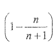
9. The system of claim 8, wherein n comprises a value between 3 and 6, inclusive.
10. The system, of claim 1 , further comprising a total of n rotors, wherein the maximum flow-through area comprises a fraction of a total flow area of the gaseous fluid stream, the fraction comprising a value between and 0.5.

1 1. An apparatus, comprising:
a rotary valve disposed in a gaseous flow stream, comprising:
a first rotor and a second rotor wherein the rotors in a first position close the gaseous flow stream and in a second position comprise a maximum flow-through area that is more than 50% of a total flow area of the gaseous flow stream; and a stator coupled to the rotors, the stator having a flow-through area comprising the maximum flow-through area.
12. The apparatus of claim 1 1 , wherein the first rotor and second rotor rotate simultaneously and in opposite directions.
13. The apparatus of claim 12, further comprising a single actuator that engages both the first rotor and the second rotor.
14. The apparatus of claim 1 1 , wherein the first rotor and second rotor comprise a high temperature material, and wherein the stator comprises stainless steel.
15. The apparatus of claim 14, wherein the gaseous flow stream comprises an engine related fluid conduit comprising a fluid conduit selected from the fluid conduits consisting of an exhaust fluid conduit, an EGR fluid conduit, and an EGR cooler bypass fluid conduit.
16. An article of manufacture, comprising:
a first rotor having a first flow-through area comprising more than 50% of a total first rotor flow area and further having a first ridged arc member;
a second rotor having a second flow-through area comprising more than 50% of a total second rotor flow area and further having a second ridged arc member;
an upstream stator and a downstream stator, each stator comprising a co-extensive stator flow-through area and a co-extensive .structural area;
an actuator comprising an engagement gear, wherein the engagement gear disposed between the first ridged arc member and the second ridged arc member, wherein a turn of the engagement gear moves the first ridged arc member and the second ridged arc member in opposing directions; and
wherein the first rotor and second rotor are phased such that:
at a first position the first rotor and second rotor co-ordinate to cover the coextensive stator flow-through area; and
at a second position, of the engagement gear the first flow -through area and the second flow through area are co-extensive and comprise the co-extensive stator flow-through area.
17. The article of manufacture of claim 16, further comprising a spacer engaging the upstream stator and the downstream stator and having an axial extent encompassing the upstream stator and the downstream stator,
18. The article of manufacture of claim 17, further comprising a ceramic spacer disposed between the actuator and the spacer.
19. The article of manufacture of eiaim 16, wherein the upstream stator and the downstream stator comprise stainless steel.
20. The article of manufacture of claim 16, further comprising a first beveled washer disposed between the upstream, stator and the first rotor, and a second beveled washer disposed between the downstream stator and the second rotor.
21. The article of manufacture of claim 16, wherein the first flow-through area comprises 55% to 75% of the total first rotor flow area, and wherein the second flow- through area comprises 55% to 75% of the total second rotor flow area.
Applications Claiming Priority (2)
| Application Number | Priority Date | Filing Date | Title |
|---|---|---|---|
| US12/764,478 | 2010-04-21 | ||
| US12/764,478 US8720423B2 (en) | 2010-04-21 | 2010-04-21 | Multi-rotor flow control valve |
Publications (2)
| Publication Number | Publication Date |
|---|---|
| WO2011133652A2 true WO2011133652A2 (en) | 2011-10-27 |
| WO2011133652A3 WO2011133652A3 (en) | 2011-12-22 |
Family
ID=44815020
Family Applications (1)
| Application Number | Title | Priority Date | Filing Date |
|---|---|---|---|
| PCT/US2011/033222 Ceased WO2011133652A2 (en) | 2010-04-21 | 2011-04-20 | Multi-rotor flow control valve |
Country Status (2)
| Country | Link |
|---|---|
| US (1) | US8720423B2 (en) |
| WO (1) | WO2011133652A2 (en) |
Families Citing this family (9)
| Publication number | Priority date | Publication date | Assignee | Title |
|---|---|---|---|---|
| WO2008154919A2 (en) * | 2007-06-19 | 2008-12-24 | Danfoss A/S | An expansion valve with a distributor |
| US20130203259A1 (en) * | 2012-02-07 | 2013-08-08 | Lam Research Corporation | Pressure control valve assembly of plasma processing chamber and rapid alternating process |
| US8974201B2 (en) * | 2012-02-23 | 2015-03-10 | Ge Oil & Gas Compression Systems, Llc | Rotating compressor valve |
| EP3303848B1 (en) | 2015-06-05 | 2022-08-24 | MTD products Inc | Blower with intake closure |
| WO2018005592A1 (en) | 2016-06-28 | 2018-01-04 | University Of Iowa Research Foundation | Medical devices including rotary valve |
| JP7119007B2 (en) | 2017-06-14 | 2022-08-16 | バット ホールディング アーゲー | Assembly having first and second chambers |
| US20210404557A1 (en) * | 2020-06-29 | 2021-12-30 | Transportation Ip Holdings, Llc | Valve assembly |
| DE102021117773A1 (en) | 2021-07-09 | 2023-01-12 | Viega Technology Gmbh & Co. Kg | Valve for regulating a flow of a medium |
| EP4491964A1 (en) * | 2023-07-11 | 2025-01-15 | Viessmann Climate Solutions SE | Device for adjusting an air volume flow |
Family Cites Families (31)
| Publication number | Priority date | Publication date | Assignee | Title |
|---|---|---|---|---|
| US1054020A (en) * | 1912-02-23 | 1913-02-25 | Emil J Mougette | Combination plug-cock. |
| US1247682A (en) * | 1915-04-22 | 1917-11-27 | Bell & Howell Co | Light-control mechanism for cinematographic and like apparatus. |
| US1969375A (en) * | 1930-05-22 | 1934-08-07 | W K M Company Inc | Rotary gate valve |
| US1986252A (en) * | 1930-12-13 | 1935-01-01 | William F Conran | Regulator device |
| US1964663A (en) * | 1933-02-25 | 1934-06-26 | Fred F Gossler | Sliding valve |
| GB573715A (en) | 1944-02-01 | 1945-12-03 | Armstrong Whitworth Co Eng | Improvements in and relating to two-stroke cycle internal combustion engines |
| GB700789A (en) | 1951-07-18 | 1953-12-09 | David F Wiseman & Sons Ltd | Improvements connected with rotary valves |
| US3063468A (en) * | 1958-07-19 | 1962-11-13 | Aero Etudes Conseils | Remotely controlled valve system |
| US3396904A (en) * | 1967-03-27 | 1968-08-13 | Jan Air Inc | Adjustable air inlet closure |
| GB1385877A (en) | 1971-07-31 | 1975-03-05 | Cav Ltd | Transducers |
| US4092963A (en) | 1977-02-24 | 1978-06-06 | Vrooman Richard A | Vaporizer-regulator, liquid fuel |
| US4134377A (en) | 1977-09-29 | 1979-01-16 | Borg-Warner Corporation | Exhaust gas recirculation control valve and heat exchanger |
| US4258687A (en) | 1979-10-09 | 1981-03-31 | Ford Motor Company | Engine with integral mounted EGR cooler |
| US4453527A (en) * | 1981-12-28 | 1984-06-12 | Ford Motor Company | Insulated diesel engine combustion chamber |
| US4532961A (en) * | 1982-11-22 | 1985-08-06 | Fisher Controls International, Inc. | Bidirectional disc throttling valve |
| US4554943A (en) | 1983-12-02 | 1985-11-26 | Fisher Controls International, Inc. | Single disc rotary valve |
| US5067319A (en) | 1989-02-15 | 1991-11-26 | Steyr-Daimler-Puch Ag | System for purifying the exhaust gases of diesel engines |
| US5322043A (en) * | 1992-08-05 | 1994-06-21 | Shriner Robert D | Spiral spin charge or sheathing system |
| US5417083A (en) * | 1993-09-24 | 1995-05-23 | American Standard Inc. | In-line incremetally adjustable electronic expansion valve |
| US6192922B1 (en) * | 1999-06-01 | 2001-02-27 | Synetics Solutions Inc. | Airflow control valve for a clean room |
| DE60034962T2 (en) | 1999-12-14 | 2008-01-24 | Cooper-Standard Automotive Inc., Findlay | INTEGRATED EXHAUST GAS RECOVERY VALVE |
| DE60205959T2 (en) | 2001-02-07 | 2006-01-12 | Calsonic Kansei Corp. | Valve arrangement for engine exhaust system |
| JP4156830B2 (en) | 2001-12-13 | 2008-09-24 | エドワーズ株式会社 | Vacuum pump |
| DE10207922A1 (en) | 2002-02-23 | 2003-09-04 | Daimler Chrysler Ag | Control valve, in particular for an internal combustion engine, for the controlled return of exhaust gas |
| EP1426603B2 (en) | 2002-12-06 | 2010-08-25 | Renault S.A.S. | Exhaust gas recirculation |
| GB0320986D0 (en) | 2003-09-08 | 2003-10-08 | Ricardo Uk Ltd | Automotive turbo charger systems |
| US7621128B2 (en) | 2005-12-02 | 2009-11-24 | Borgwarner Inc. | Combined EGR valve and cooler by-pass |
| US20070144170A1 (en) | 2005-12-22 | 2007-06-28 | Caterpillar Inc. | Compressor having integral EGR valve and mixer |
| US8210205B2 (en) * | 2006-03-09 | 2012-07-03 | Michaels Gregory A | Rotary valve assembly |
| ATE443806T1 (en) | 2006-07-06 | 2009-10-15 | Cooper Standard Automotive D | EXHAUST GAS RECIRCULATION VALVE |
| US7363919B1 (en) | 2007-01-05 | 2008-04-29 | Ford Global Technologies, Llc | Integrated exhaust gas recirculation valve and cooler system |
-
2010
- 2010-04-21 US US12/764,478 patent/US8720423B2/en active Active
-
2011
- 2011-04-20 WO PCT/US2011/033222 patent/WO2011133652A2/en not_active Ceased
Also Published As
| Publication number | Publication date |
|---|---|
| WO2011133652A3 (en) | 2011-12-22 |
| US20110260087A1 (en) | 2011-10-27 |
| US8720423B2 (en) | 2014-05-13 |
Similar Documents
| Publication | Publication Date | Title |
|---|---|---|
| US8720423B2 (en) | Multi-rotor flow control valve | |
| EP2321508B1 (en) | Butterfly valve for turbocharger systems | |
| US8863529B2 (en) | Variable pressure ratio compressor | |
| US7946806B2 (en) | Gas turbine engine systems and related methods involving heat exchange | |
| EP3081765B1 (en) | Engine bypass valve | |
| CN104246142B (en) | Rotary vane actuator operated air valve | |
| US9926840B2 (en) | Rotatable diverter valve | |
| EP2803845A1 (en) | Heat exchange arrangement | |
| CN105102801A (en) | Low pressure exhaust gas recirculation module cross-reference to related applications | |
| WO2011130015A2 (en) | Multifunction valve | |
| US20120067061A1 (en) | Bleed valve | |
| US10774732B2 (en) | Exhaust-gas turbocharger with adjustable turbine geometry | |
| CN103154468A (en) | Turbocharger egr module | |
| CA2730125C (en) | Exhaust gas recirculation butterfly valve | |
| EP2818640A2 (en) | Turbocharger with annular rotary bypass valve for the turbine, and catalyst disposed in the bypass channel of the turbine housing | |
| US8479717B2 (en) | Three-way controllable valve | |
| CN105317538A (en) | Exhaust system with remote multi-valve exhaust valves | |
| EP2964918B1 (en) | A digital waste gate valve arrangement and method of operating a digital waste gate valve arrangement in an internal combustion engine | |
| EP2815133B1 (en) | Turbocharged internal combustion piston engine comprising a waste gate valve arrangement and method of controlling gas flow by-passing a turbine section of the turbocharger unit | |
| US12540676B2 (en) | Fluid control valve | |
| JP2010013972A (en) | Variable capacity type turbocharger | |
| US11448139B2 (en) | Fueldraulic air valve | |
| EP3144508B1 (en) | Electromechanical actuator to operate a utilization device of an internal combustion engine | |
| EP3805541B1 (en) | Synchronized air modulating system | |
| CN113039353A (en) | Valve assembly and method |
Legal Events
| Date | Code | Title | Description |
|---|---|---|---|
| 121 | Ep: the epo has been informed by wipo that ep was designated in this application |
Ref document number: 11772623 Country of ref document: EP Kind code of ref document: A2 |
|
| NENP | Non-entry into the national phase |
Ref country code: DE |
|
| 122 | Ep: pct application non-entry in european phase |
Ref document number: 11772623 Country of ref document: EP Kind code of ref document: A2 |