EP2803845A1 - Heat exchange arrangement - Google Patents
Heat exchange arrangement Download PDFInfo
- Publication number
- EP2803845A1 EP2803845A1 EP14162192.0A EP14162192A EP2803845A1 EP 2803845 A1 EP2803845 A1 EP 2803845A1 EP 14162192 A EP14162192 A EP 14162192A EP 2803845 A1 EP2803845 A1 EP 2803845A1
- Authority
- EP
- European Patent Office
- Prior art keywords
- conduit
- heat exchange
- fluid
- valve
- exchange arrangement
- Prior art date
- Legal status (The legal status is an assumption and is not a legal conclusion. Google has not performed a legal analysis and makes no representation as to the accuracy of the status listed.)
- Granted
Links
- 239000012530 fluid Substances 0.000 claims abstract description 57
- 239000012809 cooling fluid Substances 0.000 claims abstract description 7
- 230000035939 shock Effects 0.000 claims abstract description 5
- 239000003570 air Substances 0.000 claims description 49
- 238000000034 method Methods 0.000 claims description 7
- 238000011144 upstream manufacturing Methods 0.000 claims description 6
- 230000004044 response Effects 0.000 claims description 4
- 230000008859 change Effects 0.000 claims description 3
- 239000000295 fuel oil Substances 0.000 claims description 2
- 239000010705 motor oil Substances 0.000 claims description 2
- 238000001816 cooling Methods 0.000 description 17
- 239000000446 fuel Substances 0.000 description 6
- 230000006835 compression Effects 0.000 description 4
- 238000007906 compression Methods 0.000 description 4
- 238000004891 communication Methods 0.000 description 3
- 230000001276 controlling effect Effects 0.000 description 3
- 239000000463 material Substances 0.000 description 3
- 230000008646 thermal stress Effects 0.000 description 3
- 238000012986 modification Methods 0.000 description 2
- 230000004048 modification Effects 0.000 description 2
- 230000001141 propulsive effect Effects 0.000 description 2
- 239000004215 Carbon black (E152) Substances 0.000 description 1
- 229910000831 Steel Inorganic materials 0.000 description 1
- RTAQQCXQSZGOHL-UHFFFAOYSA-N Titanium Chemical compound [Ti] RTAQQCXQSZGOHL-UHFFFAOYSA-N 0.000 description 1
- 239000004411 aluminium Substances 0.000 description 1
- XAGFODPZIPBFFR-UHFFFAOYSA-N aluminium Chemical compound [Al] XAGFODPZIPBFFR-UHFFFAOYSA-N 0.000 description 1
- 229910052782 aluminium Inorganic materials 0.000 description 1
- 238000013459 approach Methods 0.000 description 1
- 230000000740 bleeding effect Effects 0.000 description 1
- 238000002485 combustion reaction Methods 0.000 description 1
- 238000010276 construction Methods 0.000 description 1
- 239000002826 coolant Substances 0.000 description 1
- 230000002939 deleterious effect Effects 0.000 description 1
- 238000013461 design Methods 0.000 description 1
- 229930195733 hydrocarbon Natural products 0.000 description 1
- 150000002430 hydrocarbons Chemical class 0.000 description 1
- 229910001026 inconel Inorganic materials 0.000 description 1
- 230000004941 influx Effects 0.000 description 1
- 239000007788 liquid Substances 0.000 description 1
- 239000011159 matrix material Substances 0.000 description 1
- 238000002844 melting Methods 0.000 description 1
- 230000008018 melting Effects 0.000 description 1
- 238000002360 preparation method Methods 0.000 description 1
- 230000001105 regulatory effect Effects 0.000 description 1
- 239000010959 steel Substances 0.000 description 1
- 230000035882 stress Effects 0.000 description 1
- 239000010936 titanium Substances 0.000 description 1
- 229910052719 titanium Inorganic materials 0.000 description 1
Images
Classifications
-
- F—MECHANICAL ENGINEERING; LIGHTING; HEATING; WEAPONS; BLASTING
- F02—COMBUSTION ENGINES; HOT-GAS OR COMBUSTION-PRODUCT ENGINE PLANTS
- F02C—GAS-TURBINE PLANTS; AIR INTAKES FOR JET-PROPULSION PLANTS; CONTROLLING FUEL SUPPLY IN AIR-BREATHING JET-PROPULSION PLANTS
- F02C7/00—Features, components parts, details or accessories, not provided for in, or of interest apart form groups F02C1/00 - F02C6/00; Air intakes for jet-propulsion plants
- F02C7/12—Cooling of plants
- F02C7/14—Cooling of plants of fluids in the plant, e.g. lubricant or fuel
- F02C7/141—Cooling of plants of fluids in the plant, e.g. lubricant or fuel of working fluid
-
- F—MECHANICAL ENGINEERING; LIGHTING; HEATING; WEAPONS; BLASTING
- F02—COMBUSTION ENGINES; HOT-GAS OR COMBUSTION-PRODUCT ENGINE PLANTS
- F02K—JET-PROPULSION PLANTS
- F02K3/00—Plants including a gas turbine driving a compressor or a ducted fan
- F02K3/08—Plants including a gas turbine driving a compressor or a ducted fan with supplementary heating of the working fluid; Control thereof
- F02K3/105—Heating the by-pass flow
- F02K3/115—Heating the by-pass flow by means of indirect heat exchange
-
- F—MECHANICAL ENGINEERING; LIGHTING; HEATING; WEAPONS; BLASTING
- F05—INDEXING SCHEMES RELATING TO ENGINES OR PUMPS IN VARIOUS SUBCLASSES OF CLASSES F01-F04
- F05D—INDEXING SCHEME FOR ASPECTS RELATING TO NON-POSITIVE-DISPLACEMENT MACHINES OR ENGINES, GAS-TURBINES OR JET-PROPULSION PLANTS
- F05D2260/00—Function
- F05D2260/20—Heat transfer, e.g. cooling
- F05D2260/213—Heat transfer, e.g. cooling by the provision of a heat exchanger within the cooling circuit
-
- Y—GENERAL TAGGING OF NEW TECHNOLOGICAL DEVELOPMENTS; GENERAL TAGGING OF CROSS-SECTIONAL TECHNOLOGIES SPANNING OVER SEVERAL SECTIONS OF THE IPC; TECHNICAL SUBJECTS COVERED BY FORMER USPC CROSS-REFERENCE ART COLLECTIONS [XRACs] AND DIGESTS
- Y02—TECHNOLOGIES OR APPLICATIONS FOR MITIGATION OR ADAPTATION AGAINST CLIMATE CHANGE
- Y02T—CLIMATE CHANGE MITIGATION TECHNOLOGIES RELATED TO TRANSPORTATION
- Y02T50/00—Aeronautics or air transport
- Y02T50/60—Efficient propulsion technologies, e.g. for aircraft
Definitions
- the present invention relates to a heat exchange arrangement and a method of controlling a heat exchange arrangement, and particularly to a heat exchange arrangement for a gas turbine engine.
- Figure 1 shows a gas turbine engine 10 comprising an air intake 12 and a propulsive fan 14 that generates two airflows A and B.
- the gas turbine engine 10 comprises, in axial flow A, an intermediate pressure compressor 16, a high pressure compressor 18, a combustor 20, a high pressure turbine 22, an intermediate pressure turbine 24, a low pressure turbine 26 and an exhaust nozzle.
- Each turbine 22, 24, 26 comprises rotating turbine rotors 27 and stationary nozzle guide vanes (NGVs) 29.
- a nacelle 30 surrounds the gas turbine engine 10 and defines, in axial flow B, a bypass duct 32.
- the air exiting the combustor 20 is generally at a very high temperature, which generally approaches or exceeds the melting point of the materials used in turbine rotors 27 and NGVs 29. Consequently, relatively cool compressor air from the compressors 16, 18 is used to cool components downstream of the combustor such as the turbine rotors 27 and NGVs 29, thereby preventing damage to the components, and increasing their operating life.
- the compressor air is passed through an interior of the rotors 27 and / or NGVs 29, and out through holes to provide a cooling air film.
- Specific fuel consumption can be improved (i.e. reduced) by increasing the temperature of the combustion products exiting the combustor (known as the turbine entry temperature (TET).
- TET turbine entry temperature
- specific fuel consumption can be improved by increasing the pressure ratio provided by the compressors 14, 16, 18.
- suitable secondary heat exchange mediums may comprise air from the bypass duct 32, or fuel used to power the gas turbine engine, such as liquid hydrocarbon based fuel.
- the present invention seeks to address some or all of the above problems.
- a heat exchange arrangement for a gas turbine engine comprising: a first conduit for an engine component cooling fluid and a second conduit for a second fluid, a heat exchange portion in which fluids flowing through the first and second conduits are in a heat exchange relationship; a valve configured to moderate the mass flow rate of the fluid in the second conduit through the heat exchange portion; and a divertor valve configured to divert fluid from the first conduit into the second conduit upstream of the heat exchanger portion.
- the invention provides a heat exchange arrangement in which large thermal gradients which may otherwise damage the heat exchange arrangement are prevented by controlling diversion of warmer fluid from the first conduit into the second conduit at a position upstream of the heat exchanger portion. This ensures that the fluid in the second conduit initially reaches the heat exchanger at a warmer temperature to eliminate or reduce thermally induced stresses in the heat exchanger, which in turn increases the longevity of the heat exchange arrangement.
- the arrangement is capable of reacting as quickly as possible to cooling requirements, thereby increasing cooled component life, while preventing damage to the heat exchange arrangement from occurring.
- the divert valve may be located downstream of the heat exchange portion.
- the second fluid may comprise any of air, fuel or engine oil, and the second fluid may comprise bypass air. Where the second fluid comprises bypass air, the second fluid conduit may be located within the bypass duct of the gas turbine engine.
- a controller may be configured to control the divert valve in response to a signal to moderate the mass flow rate of fluid in the second conduit.
- the flow may be diverted as the mass flow rate in the second conduit is moderated or before the mass flow rate in the second conduit is moderated.
- the controller may be set to stop the diverted flow after a predetermined time period or once the temperature of fluid in the first conduit reaches a predetermined temperature after the divert valve has opened.
- the mass flow rate in the first conduit may be increased temporarily whilst the flow is being diverted so that the net flow to the cooled components downstream of the divertor valve is unchanged.
- a temperature sensor may be located within an outlet of the first fluid conduit. Accordingly, the temperature sensor senses the temperature of the component cooling fluid after it is cooled by the second fluid.
- the valve may comprise a butterfly valve.
- Butterfly valves have been found to be particularly suitable for the invention, since they are suitable for accurately controlling the flow rate of a fluid.
- the second fluid conduit may comprise an outlet downstream of the heat exchanger portion, the outlet being configured to accelerate fluid flowing out of the outlet.
- the second fluid comprises bypass duct air. Accordingly, the velocity of the second fluid can be accelerated at the outlet to match the velocity of air in the bypass duct.
- Figure 1 shows a gas turbine engine 10 comprising an air intake 12 and a propulsive fan 14 that generates two airflows A and B.
- the gas turbine engine 10 comprises, in axial flow A, an intermediate pressure compressor 16, a high pressure compressor 18, a combustor 20, a high pressure turbine 22, an intermediate pressure turbine 24, a low pressure turbine 26 and an exhaust nozzle.
- Each turbine 22, 24, 26 comprises rotating turbine rotors 27 and stationary nozzle guide vanes (NGVs) 29.
- a nacelle 30 surrounds the gas turbine engine 10 and defines, in axial flow B, a bypass duct 32.
- the gas turbine engine 10 includes a heat exchange arrangement 40, as shown diagrammatically in further detail in Figure 2 .
- the arrangement comprises a first conduit 46 for an engine component cooling fluid.
- the engine component cooling fluid comprises high pressure compressor air supplied by the high pressure compressor 18, though air could alternatively be supplied from the intermediate pressure compressor 16.
- the arrangement also comprises a second conduit 44 for a second fluid.
- the second fluid comprises bypass air supplied from the bypass duct 32.
- the second conduit 44 is located within the bypass duct 32 such that when the engine 10 is in operation, bypass air can flow directly into an inlet 48 of the second conduit 44.
- the temperature of bypass air entering the inlet 48 varies from around -40° C to around 80° C during operation.
- the heat exchange arrangement 40 comprises a heat exchange portion 42 through which the fluid in the first and second conduits 44, 46 pass. Fluids flowing through the first and second conduits 44, 46 in the heat exchange portion 42 are in a heat exchange relationship such the relatively hot high pressure compressor air flowing through the first conduit 46 is cooled by the relatively cool bypass air flowing through the second conduit 44.
- the heat exchange portion 42 comprises a matrix type heat exchanger formed of a material having high structural strength and suitable thermal conductivity such as steel, inconel, aluminium or titanium. Examples of suitable heat exchangers include plate-fin, plate-plate or tube type depending on pressure and temperature requirements.
- the described embodiment comprises a U-tube cross-counterflow arrangement. such an arrangement is preferred for high temperature and high pressure applications with moderate flow and heat exchange requirements.
- Other suitable heat exchanger arrangements comprise cross, counter, parallel or cross-counter flow arrangements, which may be suitable in situations having different flow, temperature and heat exchange requirements.
- the arrangement 40 further comprises a valve 48 located within the second conduit 44, and configured to moderate the flow rate of the second fluid through the second conduit 44.
- the valve 48 is located upstream of the heat exchange portion 42, though the valve 48 could alternatively be located downstream of the heat exchange portion 42, provided it is configured to moderate the flow rate of the second fluid through the second conduit 44.
- the valve 48 is actuable between open and closed positions and is thereby configured to moderate the mass flow rate of the bypass air flowing through the second conduit 44 in use.
- the valve 48 could be of any suitable type which can be operated between an open position in which fluid flow is substantially unrestricted, and a closed position in which fluid flow is substantially stopped, and preferably to positions in between open and closed positions.
- the valve 48 comprises a butterfly valve.
- the arrangement 40 includes a temperature sensor 50 which is configured to sense the temperature of the compressor air after it has passed through the heat exchange portion 42, i.e. in the first fluid flow, downstream of the heat exchange portion 42.
- the temperature sensor 50 comprises any sensor capable of producing an electrical signal in response to a temperature change, and in the described embodiment comprises a thermocouple.
- the temperature sensor 50 is in signal communication with a valve controller 52.
- the valve controller 52 is in turn in signal communication with the valve 48, and is configured to provide a signal to actuate the valve between the open and closed positions, and preferably to intermediate positions, to increase or reduce the mass flow rate through the second conduit 44.
- the valve controller 52 is also in signal communication with an engine control unit (ECU) 54, which is configured to send a signal to the valve controller 52 to command a desired heat exchanger outlet compressor air temperature.
- ECU engine control unit
- a valve 56 is provided in the heat exchanger outlet line 46 from which a portion can be diverted through conduit 58 into the cold stream 44.
- the conduit may open into the conduit downstream or upstream of the valve 48 and the volume of hot fluid diverted through valve 56 is variable depending on one or more of the volume flow through valve 48, the temperature of the fluid in conduit 44, the time elapsed after the opening of valve 48, and the temperature of the fluid sensed by sensor 50.
- air is compressed by the compressors 16, 18, and a portion of the air from the high pressure compressor 18, or possibly the intermediate compressor 16, is directed through the first conduit 46 to the heat exchange portion 42.
- the fan 14 is also operated, such that air flows through the duct 32. A portion of this fan air is directed into the second fluid conduit 44 through the inlet 48.
- the temperature of the air cooled components will vary somewhat, and varying cooling rates provided by the cooling air (i.e. flow rates or temperatures of the first fluid) may therefore be required.
- the amount and temperature of cooling air is regulated by the ECU 54.
- a signal is sent from the ECU 54 to the valve controller 52 commanding an engine component coolant fluid temperature in accordance with cooling requirements calculated by the ECU 54.
- the engine component fluid temperature may be chosen by the ECU 54 on the basis of engine operating conditions such as turbine entry temperature (TET) in order to maintain the cooled turbine components below a predetermined temperature, or to obtain a required life of the cooled component.
- TET turbine entry temperature
- the temperature sensor 50 senses the temperature of the high pressure compressor air exiting the heat exchange portion 42 of the first conduit 46 and sends a signal representative of a first sensed temperature to the valve controller 52.
- the valve controller 52 compares the first sensed temperature with the required temperature. Where the required temperature and the first sensed temperature differ by more than a predetermined minimum amount, the valve controller 52 actuates the valve 48 to either open the valve in response to the engine component fluid temperature requirement. For example, where the first sensed temperature is below the required temperature, the valve controller 52 sends a signal to close the valve 48, either completely, or to an intermediate position in which the flow rate through the first passage 46 is reduced, whereas where the first sensed temperature is above the required temperature, the valve controller 52 sends a signal to open the valve 48.
- valve 48 When the valve 48 opens the temperature difference between the air in the conduit and the heat exchanger body can cause thermal stress which can have a deleterious effect on the life of the heat exchanger.
- the ECU 54 sends a signal to a controller for the valve 56 which opens the valve to divert a small bleed of fluid from the hot, higher pressure side to the fluid 44 which increases the heat exchanger cold side temperature to reduce the temperature difference and protect the heat exchanger.
- the ECU can be programmed to open valve 56 before valve 48 is opened in preparation for the cold air 44 being supplied to the heat exchanger 42.
- the valves 56 and 48 may open simultaneously.
- Valve 56 may be closed after a predetermined period, or once temperature sensor 50 has achieved a predetermined reading following the initial adjustment caused by the influx of the cold air.
- the invention provides a heat exchange arrangement having a number of advantages over prior arrangements.
- the architecture to reduce thermal stress on the heat exchanger is simple and requires a relatively simple control arrangement, comprising in one embodiment a thermocouple, an RC circuit, a transistor and a valve actuator.
- the arrangement alleviates or minimises thermal shock of the components during use, thereby increasing the life of the heat exchange arrangement.
- the control system can be added to an existing heat exchange arrangement, such that no modifications are required to the ECU.
- different materials may be used in the construction of the heat exchange arrangement.
- Different first and second fluids could be employed.
Landscapes
- Engineering & Computer Science (AREA)
- Chemical & Material Sciences (AREA)
- Combustion & Propulsion (AREA)
- Mechanical Engineering (AREA)
- General Engineering & Computer Science (AREA)
- Control Of Turbines (AREA)
- Heat-Exchange Devices With Radiators And Conduit Assemblies (AREA)
Abstract
Description
- The present invention relates to a heat exchange arrangement and a method of controlling a heat exchange arrangement, and particularly to a heat exchange arrangement for a gas turbine engine.
-
Figure 1 shows agas turbine engine 10 comprising anair intake 12 and apropulsive fan 14 that generates two airflows A and B. Thegas turbine engine 10 comprises, in axial flow A, anintermediate pressure compressor 16, ahigh pressure compressor 18, acombustor 20, ahigh pressure turbine 22, anintermediate pressure turbine 24, alow pressure turbine 26 and an exhaust nozzle. Eachturbine turbine rotors 27 and stationary nozzle guide vanes (NGVs) 29. Anacelle 30 surrounds thegas turbine engine 10 and defines, in axial flow B, abypass duct 32. - The air exiting the
combustor 20 is generally at a very high temperature, which generally approaches or exceeds the melting point of the materials used inturbine rotors 27 andNGVs 29. Consequently, relatively cool compressor air from thecompressors turbine rotors 27 andNGVs 29, thereby preventing damage to the components, and increasing their operating life. The compressor air is passed through an interior of therotors 27 and / orNGVs 29, and out through holes to provide a cooling air film. - In gas turbine engine design, there is a continuing requirement for improved specific fuel consumption. Specific fuel consumption can be improved (i.e. reduced) by increasing the temperature of the combustion products exiting the combustor (known as the turbine entry temperature (TET). Alternatively or in addition, specific fuel consumption can be improved by increasing the pressure ratio provided by the
compressors - However, as TET increases, a larger mass flow of cooling air is required in order to maintain the components downstream of the combustor below their maximum temperature. Furthermore, as the compression ratio of the compressed air increases, so does the temperature of the compressor air. In some cases, the compressor air provided by the
high pressure compressor 18 can reach temperatures in excess of 700° C. Consequently, the cooling capacity (i.e. the amount of heat that can be removed by the air from a hot fluid at a given temperature) of a given mass of air compressed by thecompressors - One way to overcome this problem is to cool compressor air used for cooling by passing some or all of the cooling air through a heat exchanger such that the cooling air is in heat exchange relationship with a secondary heat exchange medium comprising a relatively cooler fluid. In a gas turbine engine for an aircraft, suitable secondary heat exchange mediums may comprise air from the
bypass duct 32, or fuel used to power the gas turbine engine, such as liquid hydrocarbon based fuel. - One example of such an arrangement is described in
EP 0469825 in which bypass air is used as the secondary heat exchange medium. However, repeated sudden exposure of the heat exchanger to large thermal gradients, such as will occur when either cooling air or secondary heat exchange medium is bypassed around the heat exchanger, can induce high thermal stresses in the heat exchanger. This may cause sudden or eventual failure of the heat exchanger after a limited number of cycles. Consequently, there is a requirement to increase the longevity of the heat exchanger in such arrangements. - The present invention seeks to address some or all of the above problems.
- According to a first aspect of the present invention, there is provided a heat exchange arrangement for a gas turbine engine, the heat exchange arrangement comprising: a first conduit for an engine component cooling fluid and a second conduit for a second fluid, a heat exchange portion in which fluids flowing through the first and second conduits are in a heat exchange relationship; a valve configured to moderate the mass flow rate of the fluid in the second conduit through the heat exchange portion; and a divertor valve configured to divert fluid from the first conduit into the second conduit upstream of the heat exchanger portion.
- Accordingly, the invention provides a heat exchange arrangement in which large thermal gradients which may otherwise damage the heat exchange arrangement are prevented by controlling diversion of warmer fluid from the first conduit into the second conduit at a position upstream of the heat exchanger portion. This ensures that the fluid in the second conduit initially reaches the heat exchanger at a warmer temperature to eliminate or reduce thermally induced stresses in the heat exchanger, which in turn increases the longevity of the heat exchange arrangement. On the other hand, the arrangement is capable of reacting as quickly as possible to cooling requirements, thereby increasing cooled component life, while preventing damage to the heat exchange arrangement from occurring.
- The divert valve may be located downstream of the heat exchange portion. The second fluid may comprise any of air, fuel or engine oil, and the second fluid may comprise bypass air. Where the second fluid comprises bypass air, the second fluid conduit may be located within the bypass duct of the gas turbine engine.
- A controller may be configured to control the divert valve in response to a signal to moderate the mass flow rate of fluid in the second conduit. The flow may be diverted as the mass flow rate in the second conduit is moderated or before the mass flow rate in the second conduit is moderated. The controller may be set to stop the diverted flow after a predetermined time period or once the temperature of fluid in the first conduit reaches a predetermined temperature after the divert valve has opened.
- The mass flow rate in the first conduit may be increased temporarily whilst the flow is being diverted so that the net flow to the cooled components downstream of the divertor valve is unchanged.
- In a preferred embodiment, a temperature sensor may be located within an outlet of the first fluid conduit. Accordingly, the temperature sensor senses the temperature of the component cooling fluid after it is cooled by the second fluid.
- Preferably, the valve may comprise a butterfly valve. Butterfly valves have been found to be particularly suitable for the invention, since they are suitable for accurately controlling the flow rate of a fluid.
- The second fluid conduit may comprise an outlet downstream of the heat exchanger portion, the outlet being configured to accelerate fluid flowing out of the outlet. Such an arrangement is particularly suitable where the second fluid comprises bypass duct air. Accordingly, the velocity of the second fluid can be accelerated at the outlet to match the velocity of air in the bypass duct.
-
-
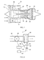
Figure 1 is a diagrammatic cross sectional view of a gas turbine engine; -
Figure 2 is a diagrammatic cross sectional view of a heat exchange arrangement; -
Figure 1 shows agas turbine engine 10 comprising anair intake 12 and apropulsive fan 14 that generates two airflows A and B. Thegas turbine engine 10 comprises, in axial flow A, anintermediate pressure compressor 16, ahigh pressure compressor 18, acombustor 20, ahigh pressure turbine 22, anintermediate pressure turbine 24, alow pressure turbine 26 and an exhaust nozzle. Eachturbine turbine rotors 27 and stationary nozzle guide vanes (NGVs) 29. Anacelle 30 surrounds thegas turbine engine 10 and defines, in axial flow B, abypass duct 32. - The
gas turbine engine 10 includes aheat exchange arrangement 40, as shown diagrammatically in further detail inFigure 2 . The arrangement comprises afirst conduit 46 for an engine component cooling fluid. The engine component cooling fluid comprises high pressure compressor air supplied by thehigh pressure compressor 18, though air could alternatively be supplied from theintermediate pressure compressor 16. The arrangement also comprises asecond conduit 44 for a second fluid. The second fluid comprises bypass air supplied from thebypass duct 32. Thesecond conduit 44 is located within thebypass duct 32 such that when theengine 10 is in operation, bypass air can flow directly into aninlet 48 of thesecond conduit 44. The temperature of bypass air entering theinlet 48 varies from around -40° C to around 80° C during operation. - The
heat exchange arrangement 40 comprises aheat exchange portion 42 through which the fluid in the first andsecond conduits second conduits heat exchange portion 42 are in a heat exchange relationship such the relatively hot high pressure compressor air flowing through thefirst conduit 46 is cooled by the relatively cool bypass air flowing through thesecond conduit 44. Theheat exchange portion 42 comprises a matrix type heat exchanger formed of a material having high structural strength and suitable thermal conductivity such as steel, inconel, aluminium or titanium. Examples of suitable heat exchangers include plate-fin, plate-plate or tube type depending on pressure and temperature requirements. The described embodiment comprises a U-tube cross-counterflow arrangement. such an arrangement is preferred for high temperature and high pressure applications with moderate flow and heat exchange requirements. Other suitable heat exchanger arrangements comprise cross, counter, parallel or cross-counter flow arrangements, which may be suitable in situations having different flow, temperature and heat exchange requirements. - The
arrangement 40 further comprises avalve 48 located within thesecond conduit 44, and configured to moderate the flow rate of the second fluid through thesecond conduit 44. In this embodiment, thevalve 48 is located upstream of theheat exchange portion 42, though thevalve 48 could alternatively be located downstream of theheat exchange portion 42, provided it is configured to moderate the flow rate of the second fluid through thesecond conduit 44. Thevalve 48 is actuable between open and closed positions and is thereby configured to moderate the mass flow rate of the bypass air flowing through thesecond conduit 44 in use. Thevalve 48 could be of any suitable type which can be operated between an open position in which fluid flow is substantially unrestricted, and a closed position in which fluid flow is substantially stopped, and preferably to positions in between open and closed positions. In the described embodiment, thevalve 48 comprises a butterfly valve. - The
arrangement 40 includes atemperature sensor 50 which is configured to sense the temperature of the compressor air after it has passed through theheat exchange portion 42, i.e. in the first fluid flow, downstream of theheat exchange portion 42. Thetemperature sensor 50 comprises any sensor capable of producing an electrical signal in response to a temperature change, and in the described embodiment comprises a thermocouple. - The
temperature sensor 50 is in signal communication with avalve controller 52. Thevalve controller 52 is in turn in signal communication with thevalve 48, and is configured to provide a signal to actuate the valve between the open and closed positions, and preferably to intermediate positions, to increase or reduce the mass flow rate through thesecond conduit 44. Thevalve controller 52 is also in signal communication with an engine control unit (ECU) 54, which is configured to send a signal to thevalve controller 52 to command a desired heat exchanger outlet compressor air temperature. - A
valve 56 is provided in the heatexchanger outlet line 46 from which a portion can be diverted throughconduit 58 into thecold stream 44. The conduit may open into the conduit downstream or upstream of thevalve 48 and the volume of hot fluid diverted throughvalve 56 is variable depending on one or more of the volume flow throughvalve 48, the temperature of the fluid inconduit 44, the time elapsed after the opening ofvalve 48, and the temperature of the fluid sensed bysensor 50. - During operation of the
engine 10, air is compressed by thecompressors high pressure compressor 18, or possibly theintermediate compressor 16, is directed through thefirst conduit 46 to theheat exchange portion 42. Thefan 14 is also operated, such that air flows through theduct 32. A portion of this fan air is directed into the secondfluid conduit 44 through theinlet 48. - During operation of the
engine 10, the temperature of the air cooled components will vary somewhat, and varying cooling rates provided by the cooling air (i.e. flow rates or temperatures of the first fluid) may therefore be required. The amount and temperature of cooling air is regulated by theECU 54. During operation, a signal is sent from theECU 54 to thevalve controller 52 commanding an engine component coolant fluid temperature in accordance with cooling requirements calculated by theECU 54. The engine component fluid temperature may be chosen by theECU 54 on the basis of engine operating conditions such as turbine entry temperature (TET) in order to maintain the cooled turbine components below a predetermined temperature, or to obtain a required life of the cooled component. - The
temperature sensor 50 senses the temperature of the high pressure compressor air exiting theheat exchange portion 42 of thefirst conduit 46 and sends a signal representative of a first sensed temperature to thevalve controller 52. Thevalve controller 52 compares the first sensed temperature with the required temperature. Where the required temperature and the first sensed temperature differ by more than a predetermined minimum amount, thevalve controller 52 actuates thevalve 48 to either open the valve in response to the engine component fluid temperature requirement. For example, where the first sensed temperature is below the required temperature, thevalve controller 52 sends a signal to close thevalve 48, either completely, or to an intermediate position in which the flow rate through thefirst passage 46 is reduced, whereas where the first sensed temperature is above the required temperature, thevalve controller 52 sends a signal to open thevalve 48. - When the
valve 48 opens the temperature difference between the air in the conduit and the heat exchanger body can cause thermal stress which can have a deleterious effect on the life of the heat exchanger. To avoid thermal shock theECU 54 sends a signal to a controller for thevalve 56 which opens the valve to divert a small bleed of fluid from the hot, higher pressure side to the fluid 44 which increases the heat exchanger cold side temperature to reduce the temperature difference and protect the heat exchanger. - The ECU can be programmed to open
valve 56 beforevalve 48 is opened in preparation for thecold air 44 being supplied to theheat exchanger 42. Alternatively, thevalves -
Valve 56 may be closed after a predetermined period, or oncetemperature sensor 50 has achieved a predetermined reading following the initial adjustment caused by the influx of the cold air. - As the flow in the
conduit 46 is used to cool components in the turbine section it may be necessary for the flow in the conduit to be temporarily increased whilst the divertvalve 56 is bleeding fluid into the flow inconduit 44 so that there is no net change in the cooling fluid available for cooling the components. - Accordingly, the invention provides a heat exchange arrangement having a number of advantages over prior arrangements. The architecture to reduce thermal stress on the heat exchanger is simple and requires a relatively simple control arrangement, comprising in one embodiment a thermocouple, an RC circuit, a transistor and a valve actuator. The arrangement alleviates or minimises thermal shock of the components during use, thereby increasing the life of the heat exchange arrangement. The control system can be added to an existing heat exchange arrangement, such that no modifications are required to the ECU.
- While the invention has been described in conjunction with the exemplary embodiments described above, many equivalent modifications and variations will be apparent to those skilled in the art when given this disclosure. Accordingly, the exemplary embodiments of the invention set forth above are considered to be illustrative and not limiting..
- For example, different materials may be used in the construction of the heat exchange arrangement. Different first and second fluids could be employed.
Claims (14)
- A heat exchange arrangement (40) for a gas turbine engine, the heat exchange arrangement comprising:a first conduit (46) for an engine component cooling fluid and a second conduit (44) for a second fluid,a heat exchange portion (42) in which fluids flowing through the first and second conduits are in a heat exchange relationship;a valve (48) configured to moderate the mass flow rate of the fluid in the second conduit through the heat exchange portion; anda divertor valve (58) configured to divert fluid from the first conduit into the second conduit upstream of the heat exchanger portion.
- A heat exchange arrangement according to claim 1, wherein the divertor valve (58) is located downstream of the heat exchange portion.
- A heat exchange arrangement according to claim 1 or claim 2, wherein the second fluid comprises any of air, fuel or engine oil.
- A heat exchange arrangement according to claim 3, wherein the second fluid comprises bypass air.
- A heat exchange arrangement according to claim 4, wherein the second fluid conduit is located within the bypass duct (32) of the gas turbine engine.
- A heat exchange arrangement further comprising a controller, wherein the controller (52) is configured to control the divertor valve (58) in response to signal to moderate the mass flow rate of fluid in the second conduit.
- A heat exchange arrangement according to claim 6, wherein the divertor valve is a butterfly valve.
- A heat exchange arrangement according to claim 1, wherein the controller is configured to actuate the valve when the rate of change of the temperature with respect to time of the fluid sensed by a temperature sensor is above a predetermined value.
- A gas turbine engine comprising a heat exchange arrangement according to any of the preceding claims.
- A method of controlling a heat exchange arrangement according to any of the preceding claims, the method comprising diverting fluid from the first conduit into the second conduit upstream of the heat exchanger portion.
- A method according to claim 10, wherein fluid is diverted from the first conduit into the second conduit whilst the flow in the second conduit is modulated.
- A method according to claim 10 or 11, wherein the flow is diverted for a predetermined period to reduce thermal shock in the heat exchanger portion.
- A method according to any of claims 10, wherein the fluid is diverted from the first conduit into the second conduit before the flow in the second conduit is modulated.
- A method according to claim 13, wherein the flow is diverted for a predetermined period to reduce thermal shock in the heat exchanger portion.
Applications Claiming Priority (1)
| Application Number | Priority Date | Filing Date | Title |
|---|---|---|---|
| GBGB1308788.7A GB201308788D0 (en) | 2013-05-16 | 2013-05-16 | Heat exchange arrangement |
Publications (2)
| Publication Number | Publication Date |
|---|---|
| EP2803845A1 true EP2803845A1 (en) | 2014-11-19 |
| EP2803845B1 EP2803845B1 (en) | 2016-06-15 |
Family
ID=48700869
Family Applications (1)
| Application Number | Title | Priority Date | Filing Date |
|---|---|---|---|
| EP14162192.0A Active EP2803845B1 (en) | 2013-05-16 | 2014-03-28 | Heat exchange arrangement |
Country Status (3)
| Country | Link |
|---|---|
| US (1) | US9624832B2 (en) |
| EP (1) | EP2803845B1 (en) |
| GB (1) | GB201308788D0 (en) |
Families Citing this family (23)
| Publication number | Priority date | Publication date | Assignee | Title |
|---|---|---|---|---|
| US11808210B2 (en) | 2015-02-12 | 2023-11-07 | Rtx Corporation | Intercooled cooling air with heat exchanger packaging |
| US10731560B2 (en) | 2015-02-12 | 2020-08-04 | Raytheon Technologies Corporation | Intercooled cooling air |
| US10371055B2 (en) | 2015-02-12 | 2019-08-06 | United Technologies Corporation | Intercooled cooling air using cooling compressor as starter |
| US10221862B2 (en) | 2015-04-24 | 2019-03-05 | United Technologies Corporation | Intercooled cooling air tapped from plural locations |
| US10480419B2 (en) | 2015-04-24 | 2019-11-19 | United Technologies Corporation | Intercooled cooling air with plural heat exchangers |
| US10830148B2 (en) | 2015-04-24 | 2020-11-10 | Raytheon Technologies Corporation | Intercooled cooling air with dual pass heat exchanger |
| US10100739B2 (en) | 2015-05-18 | 2018-10-16 | United Technologies Corporation | Cooled cooling air system for a gas turbine engine |
| US10794288B2 (en) * | 2015-07-07 | 2020-10-06 | Raytheon Technologies Corporation | Cooled cooling air system for a turbofan engine |
| US10443508B2 (en) | 2015-12-14 | 2019-10-15 | United Technologies Corporation | Intercooled cooling air with auxiliary compressor control |
| US10669940B2 (en) | 2016-09-19 | 2020-06-02 | Raytheon Technologies Corporation | Gas turbine engine with intercooled cooling air and turbine drive |
| US10550768B2 (en) | 2016-11-08 | 2020-02-04 | United Technologies Corporation | Intercooled cooled cooling integrated air cycle machine |
| US10794290B2 (en) | 2016-11-08 | 2020-10-06 | Raytheon Technologies Corporation | Intercooled cooled cooling integrated air cycle machine |
| US10961911B2 (en) | 2017-01-17 | 2021-03-30 | Raytheon Technologies Corporation | Injection cooled cooling air system for a gas turbine engine |
| US10995673B2 (en) | 2017-01-19 | 2021-05-04 | Raytheon Technologies Corporation | Gas turbine engine with intercooled cooling air and dual towershaft accessory gearbox |
| US10577964B2 (en) | 2017-03-31 | 2020-03-03 | United Technologies Corporation | Cooled cooling air for blade air seal through outer chamber |
| US10711640B2 (en) | 2017-04-11 | 2020-07-14 | Raytheon Technologies Corporation | Cooled cooling air to blade outer air seal passing through a static vane |
| US10738703B2 (en) * | 2018-03-22 | 2020-08-11 | Raytheon Technologies Corporation | Intercooled cooling air with combined features |
| US10808619B2 (en) | 2018-04-19 | 2020-10-20 | Raytheon Technologies Corporation | Intercooled cooling air with advanced cooling system |
| US10830145B2 (en) | 2018-04-19 | 2020-11-10 | Raytheon Technologies Corporation | Intercooled cooling air fleet management system |
| US10718233B2 (en) | 2018-06-19 | 2020-07-21 | Raytheon Technologies Corporation | Intercooled cooling air with low temperature bearing compartment air |
| US11255268B2 (en) | 2018-07-31 | 2022-02-22 | Raytheon Technologies Corporation | Intercooled cooling air with selective pressure dump |
| US11313276B2 (en) * | 2019-08-01 | 2022-04-26 | Rolls-Royce Deutschland Ltd & Co Kg | Supersonic gas turbine engine |
| US11492971B2 (en) | 2019-09-06 | 2022-11-08 | Raytheon Technologies Corporation | Turbine engine system with heat exchanger in bypassable secondary duct |
Citations (3)
| Publication number | Priority date | Publication date | Assignee | Title |
|---|---|---|---|---|
| EP1795708A2 (en) * | 2005-12-08 | 2007-06-13 | General Electric Company | Shrouded turbofan bleed duct |
| US20080230651A1 (en) * | 2005-09-26 | 2008-09-25 | Airbus France | Turbofan Provided With a Pre-Cooler |
| WO2014051678A1 (en) * | 2012-09-28 | 2014-04-03 | United Technologies Corporation | Gas turbine engine thermal management system for heat exchanger using bypass flow |
Family Cites Families (7)
| Publication number | Priority date | Publication date | Assignee | Title |
|---|---|---|---|---|
| US3842597A (en) * | 1973-03-16 | 1974-10-22 | Gen Electric | Gas turbine engine with means for reducing the formation and emission of nitrogen oxides |
| US5123242A (en) | 1990-07-30 | 1992-06-23 | General Electric Company | Precooling heat exchange arrangement integral with mounting structure fairing of gas turbine engine |
| US6134880A (en) * | 1997-12-31 | 2000-10-24 | Concepts Eti, Inc. | Turbine engine with intercooler in bypass air passage |
| US20010054354A1 (en) | 2000-06-21 | 2001-12-27 | Baudat Ned P. | Direct turbine air chiller/scrubber system |
| DE10355353A1 (en) | 2003-11-25 | 2005-07-21 | Alstom Technology Ltd | Method for cooling a gas stream supplied to a turbomachine, e.g. a gas turbine being used for electricity generation, includes controlling purity of cooling liquid by discharge of polluted fluid and supply of fresh fluid |
| US8397487B2 (en) * | 2011-02-28 | 2013-03-19 | General Electric Company | Environmental control system supply precooler bypass |
| GB201121428D0 (en) | 2011-12-14 | 2012-01-25 | Rolls Royce Plc | Controller |
-
2013
- 2013-05-16 GB GBGB1308788.7A patent/GB201308788D0/en not_active Ceased
-
2014
- 2014-03-28 EP EP14162192.0A patent/EP2803845B1/en active Active
- 2014-03-28 US US14/229,137 patent/US9624832B2/en active Active
Patent Citations (3)
| Publication number | Priority date | Publication date | Assignee | Title |
|---|---|---|---|---|
| US20080230651A1 (en) * | 2005-09-26 | 2008-09-25 | Airbus France | Turbofan Provided With a Pre-Cooler |
| EP1795708A2 (en) * | 2005-12-08 | 2007-06-13 | General Electric Company | Shrouded turbofan bleed duct |
| WO2014051678A1 (en) * | 2012-09-28 | 2014-04-03 | United Technologies Corporation | Gas turbine engine thermal management system for heat exchanger using bypass flow |
Also Published As
| Publication number | Publication date |
|---|---|
| GB201308788D0 (en) | 2013-06-26 |
| EP2803845B1 (en) | 2016-06-15 |
| US20140341704A1 (en) | 2014-11-20 |
| US9624832B2 (en) | 2017-04-18 |
Similar Documents
| Publication | Publication Date | Title |
|---|---|---|
| EP2803845B1 (en) | Heat exchange arrangement | |
| EP2730766B1 (en) | Heat exchange arrangement for a gas turbine | |
| US20200200085A1 (en) | Temperature-modulated recuperated gas turbine engine | |
| US7946806B2 (en) | Gas turbine engine systems and related methods involving heat exchange | |
| US8833053B2 (en) | Cooling system for an aero gas turbine engine | |
| EP2519723B1 (en) | Gas turbine engine | |
| US8601792B2 (en) | Oil cooler having adjustable heat transfer effectiveness | |
| US9739198B2 (en) | Oil and fuel circuits in a turbine engine | |
| US10208669B2 (en) | Method and device for regulating the cooling of oil in a turbomachine | |
| US20170241324A1 (en) | Thermal management system with heat recovery and method of making and using the same | |
| EP0563180A1 (en) | Heat exchange apparatus for gas turbine fluids. | |
| CN107532516A (en) | The cooling of the oil return line of turbogenerator | |
| GB2055963A (en) | Supercharging Internal Combustion Engines | |
| US20160281603A1 (en) | Gas turbine engine fluid heat management system | |
| CA2691461C (en) | Two-stage heat exchanger with interstage bypass | |
| CN208996777U (en) | The cooling air supply system of self-adjustable low-pressure turbine | |
| EP3112637B1 (en) | Air supply and conditioning system for a gas turbine | |
| EP3838762A1 (en) | Air cycle machines, air cycle machine systems, and methods of controlling air flow in air cycle machines | |
| EP3066313B1 (en) | Method for operating an internal combustion engine | |
| EP4105465A2 (en) | Oil cooling system for aircraft engine | |
| EP3460374B1 (en) | Rotating heat exchanger/bypass combo | |
| EP3037647B1 (en) | System and method for controlling bleed air temperature | |
| EP3203034A1 (en) | Thermally biased valve and anti-icing system | |
| WO2004081482A1 (en) | A bypass valve for a gas turbine engine recuperator system | |
| Cengel et al. | Mass and energy analysis of control volumes |
Legal Events
| Date | Code | Title | Description |
|---|---|---|---|
| PUAI | Public reference made under article 153(3) epc to a published international application that has entered the european phase |
Free format text: ORIGINAL CODE: 0009012 |
|
| 17P | Request for examination filed |
Effective date: 20140328 |
|
| AK | Designated contracting states |
Kind code of ref document: A1 Designated state(s): AL AT BE BG CH CY CZ DE DK EE ES FI FR GB GR HR HU IE IS IT LI LT LU LV MC MK MT NL NO PL PT RO RS SE SI SK SM TR |
|
| AX | Request for extension of the european patent |
Extension state: BA ME |
|
| R17P | Request for examination filed (corrected) |
Effective date: 20150511 |
|
| RBV | Designated contracting states (corrected) |
Designated state(s): AL AT BE BG CH CY CZ DE DK EE ES FI FR GB GR HR HU IE IS IT LI LT LU LV MC MK MT NL NO PL PT RO RS SE SI SK SM TR |
|
| RAP1 | Party data changed (applicant data changed or rights of an application transferred) |
Owner name: ROLLS-ROYCE PLC |
|
| 17Q | First examination report despatched |
Effective date: 20150716 |
|
| REG | Reference to a national code |
Ref country code: DE Ref legal event code: R079 Ref document number: 602014002293 Country of ref document: DE Free format text: PREVIOUS MAIN CLASS: F02K0003115000 Ipc: F02C0007141000 |
|
| RIC1 | Information provided on ipc code assigned before grant |
Ipc: F02C 7/141 20060101AFI20160215BHEP Ipc: F02K 3/115 20060101ALI20160215BHEP |
|
| GRAP | Despatch of communication of intention to grant a patent |
Free format text: ORIGINAL CODE: EPIDOSNIGR1 |
|
| GRAS | Grant fee paid |
Free format text: ORIGINAL CODE: EPIDOSNIGR3 |
|
| INTG | Intention to grant announced |
Effective date: 20160406 |
|
| GRAA | (expected) grant |
Free format text: ORIGINAL CODE: 0009210 |
|
| AK | Designated contracting states |
Kind code of ref document: B1 Designated state(s): AL AT BE BG CH CY CZ DE DK EE ES FI FR GB GR HR HU IE IS IT LI LT LU LV MC MK MT NL NO PL PT RO RS SE SI SK SM TR |
|
| REG | Reference to a national code |
Ref country code: CH Ref legal event code: EP Ref country code: GB Ref legal event code: FG4D |
|
| REG | Reference to a national code |
Ref country code: IE Ref legal event code: FG4D |
|
| REG | Reference to a national code |
Ref country code: AT Ref legal event code: REF Ref document number: 806634 Country of ref document: AT Kind code of ref document: T Effective date: 20160715 |
|
| REG | Reference to a national code |
Ref country code: DE Ref legal event code: R096 Ref document number: 602014002293 Country of ref document: DE |
|
| REG | Reference to a national code |
Ref country code: LT Ref legal event code: MG4D |
|
| REG | Reference to a national code |
Ref country code: NL Ref legal event code: MP Effective date: 20160615 |
|
| PG25 | Lapsed in a contracting state [announced via postgrant information from national office to epo] |
Ref country code: NO Free format text: LAPSE BECAUSE OF FAILURE TO SUBMIT A TRANSLATION OF THE DESCRIPTION OR TO PAY THE FEE WITHIN THE PRESCRIBED TIME-LIMIT Effective date: 20160915 Ref country code: FI Free format text: LAPSE BECAUSE OF FAILURE TO SUBMIT A TRANSLATION OF THE DESCRIPTION OR TO PAY THE FEE WITHIN THE PRESCRIBED TIME-LIMIT Effective date: 20160615 Ref country code: LT Free format text: LAPSE BECAUSE OF FAILURE TO SUBMIT A TRANSLATION OF THE DESCRIPTION OR TO PAY THE FEE WITHIN THE PRESCRIBED TIME-LIMIT Effective date: 20160615 |
|
| REG | Reference to a national code |
Ref country code: AT Ref legal event code: MK05 Ref document number: 806634 Country of ref document: AT Kind code of ref document: T Effective date: 20160615 |
|
| PG25 | Lapsed in a contracting state [announced via postgrant information from national office to epo] |
Ref country code: GR Free format text: LAPSE BECAUSE OF FAILURE TO SUBMIT A TRANSLATION OF THE DESCRIPTION OR TO PAY THE FEE WITHIN THE PRESCRIBED TIME-LIMIT Effective date: 20160916 Ref country code: RS Free format text: LAPSE BECAUSE OF FAILURE TO SUBMIT A TRANSLATION OF THE DESCRIPTION OR TO PAY THE FEE WITHIN THE PRESCRIBED TIME-LIMIT Effective date: 20160615 Ref country code: SE Free format text: LAPSE BECAUSE OF FAILURE TO SUBMIT A TRANSLATION OF THE DESCRIPTION OR TO PAY THE FEE WITHIN THE PRESCRIBED TIME-LIMIT Effective date: 20160615 Ref country code: NL Free format text: LAPSE BECAUSE OF FAILURE TO SUBMIT A TRANSLATION OF THE DESCRIPTION OR TO PAY THE FEE WITHIN THE PRESCRIBED TIME-LIMIT Effective date: 20160615 Ref country code: LV Free format text: LAPSE BECAUSE OF FAILURE TO SUBMIT A TRANSLATION OF THE DESCRIPTION OR TO PAY THE FEE WITHIN THE PRESCRIBED TIME-LIMIT Effective date: 20160615 Ref country code: HR Free format text: LAPSE BECAUSE OF FAILURE TO SUBMIT A TRANSLATION OF THE DESCRIPTION OR TO PAY THE FEE WITHIN THE PRESCRIBED TIME-LIMIT Effective date: 20160615 |
|
| PG25 | Lapsed in a contracting state [announced via postgrant information from national office to epo] |
Ref country code: RO Free format text: LAPSE BECAUSE OF FAILURE TO SUBMIT A TRANSLATION OF THE DESCRIPTION OR TO PAY THE FEE WITHIN THE PRESCRIBED TIME-LIMIT Effective date: 20160615 Ref country code: EE Free format text: LAPSE BECAUSE OF FAILURE TO SUBMIT A TRANSLATION OF THE DESCRIPTION OR TO PAY THE FEE WITHIN THE PRESCRIBED TIME-LIMIT Effective date: 20160615 Ref country code: IT Free format text: LAPSE BECAUSE OF FAILURE TO SUBMIT A TRANSLATION OF THE DESCRIPTION OR TO PAY THE FEE WITHIN THE PRESCRIBED TIME-LIMIT Effective date: 20160615 Ref country code: SK Free format text: LAPSE BECAUSE OF FAILURE TO SUBMIT A TRANSLATION OF THE DESCRIPTION OR TO PAY THE FEE WITHIN THE PRESCRIBED TIME-LIMIT Effective date: 20160615 Ref country code: IS Free format text: LAPSE BECAUSE OF FAILURE TO SUBMIT A TRANSLATION OF THE DESCRIPTION OR TO PAY THE FEE WITHIN THE PRESCRIBED TIME-LIMIT Effective date: 20161015 Ref country code: CZ Free format text: LAPSE BECAUSE OF FAILURE TO SUBMIT A TRANSLATION OF THE DESCRIPTION OR TO PAY THE FEE WITHIN THE PRESCRIBED TIME-LIMIT Effective date: 20160615 |
|
| PG25 | Lapsed in a contracting state [announced via postgrant information from national office to epo] |
Ref country code: PT Free format text: LAPSE BECAUSE OF FAILURE TO SUBMIT A TRANSLATION OF THE DESCRIPTION OR TO PAY THE FEE WITHIN THE PRESCRIBED TIME-LIMIT Effective date: 20161017 Ref country code: AT Free format text: LAPSE BECAUSE OF FAILURE TO SUBMIT A TRANSLATION OF THE DESCRIPTION OR TO PAY THE FEE WITHIN THE PRESCRIBED TIME-LIMIT Effective date: 20160615 Ref country code: SM Free format text: LAPSE BECAUSE OF FAILURE TO SUBMIT A TRANSLATION OF THE DESCRIPTION OR TO PAY THE FEE WITHIN THE PRESCRIBED TIME-LIMIT Effective date: 20160615 Ref country code: PL Free format text: LAPSE BECAUSE OF FAILURE TO SUBMIT A TRANSLATION OF THE DESCRIPTION OR TO PAY THE FEE WITHIN THE PRESCRIBED TIME-LIMIT Effective date: 20160615 Ref country code: BE Free format text: LAPSE BECAUSE OF FAILURE TO SUBMIT A TRANSLATION OF THE DESCRIPTION OR TO PAY THE FEE WITHIN THE PRESCRIBED TIME-LIMIT Effective date: 20160615 Ref country code: ES Free format text: LAPSE BECAUSE OF FAILURE TO SUBMIT A TRANSLATION OF THE DESCRIPTION OR TO PAY THE FEE WITHIN THE PRESCRIBED TIME-LIMIT Effective date: 20160615 |
|
| REG | Reference to a national code |
Ref country code: DE Ref legal event code: R097 Ref document number: 602014002293 Country of ref document: DE |
|
| REG | Reference to a national code |
Ref country code: FR Ref legal event code: PLFP Year of fee payment: 4 |
|
| PLBE | No opposition filed within time limit |
Free format text: ORIGINAL CODE: 0009261 |
|
| STAA | Information on the status of an ep patent application or granted ep patent |
Free format text: STATUS: NO OPPOSITION FILED WITHIN TIME LIMIT |
|
| 26N | No opposition filed |
Effective date: 20170316 |
|
| PG25 | Lapsed in a contracting state [announced via postgrant information from national office to epo] |
Ref country code: DK Free format text: LAPSE BECAUSE OF FAILURE TO SUBMIT A TRANSLATION OF THE DESCRIPTION OR TO PAY THE FEE WITHIN THE PRESCRIBED TIME-LIMIT Effective date: 20160615 |
|
| PG25 | Lapsed in a contracting state [announced via postgrant information from national office to epo] |
Ref country code: SI Free format text: LAPSE BECAUSE OF FAILURE TO SUBMIT A TRANSLATION OF THE DESCRIPTION OR TO PAY THE FEE WITHIN THE PRESCRIBED TIME-LIMIT Effective date: 20160615 |
|
| REG | Reference to a national code |
Ref country code: CH Ref legal event code: PL |
|
| PG25 | Lapsed in a contracting state [announced via postgrant information from national office to epo] |
Ref country code: MC Free format text: LAPSE BECAUSE OF FAILURE TO SUBMIT A TRANSLATION OF THE DESCRIPTION OR TO PAY THE FEE WITHIN THE PRESCRIBED TIME-LIMIT Effective date: 20160615 |
|
| REG | Reference to a national code |
Ref country code: IE Ref legal event code: MM4A |
|
| PG25 | Lapsed in a contracting state [announced via postgrant information from national office to epo] |
Ref country code: LU Free format text: LAPSE BECAUSE OF NON-PAYMENT OF DUE FEES Effective date: 20170328 |
|
| PG25 | Lapsed in a contracting state [announced via postgrant information from national office to epo] |
Ref country code: CH Free format text: LAPSE BECAUSE OF NON-PAYMENT OF DUE FEES Effective date: 20170331 Ref country code: LI Free format text: LAPSE BECAUSE OF NON-PAYMENT OF DUE FEES Effective date: 20170331 Ref country code: IE Free format text: LAPSE BECAUSE OF NON-PAYMENT OF DUE FEES Effective date: 20170328 |
|
| REG | Reference to a national code |
Ref country code: FR Ref legal event code: PLFP Year of fee payment: 5 |
|
| PG25 | Lapsed in a contracting state [announced via postgrant information from national office to epo] |
Ref country code: MT Free format text: LAPSE BECAUSE OF NON-PAYMENT OF DUE FEES Effective date: 20170328 |
|
| PG25 | Lapsed in a contracting state [announced via postgrant information from national office to epo] |
Ref country code: AL Free format text: LAPSE BECAUSE OF FAILURE TO SUBMIT A TRANSLATION OF THE DESCRIPTION OR TO PAY THE FEE WITHIN THE PRESCRIBED TIME-LIMIT Effective date: 20160615 |
|
| PG25 | Lapsed in a contracting state [announced via postgrant information from national office to epo] |
Ref country code: HU Free format text: LAPSE BECAUSE OF FAILURE TO SUBMIT A TRANSLATION OF THE DESCRIPTION OR TO PAY THE FEE WITHIN THE PRESCRIBED TIME-LIMIT; INVALID AB INITIO Effective date: 20140328 |
|
| PG25 | Lapsed in a contracting state [announced via postgrant information from national office to epo] |
Ref country code: BG Free format text: LAPSE BECAUSE OF FAILURE TO SUBMIT A TRANSLATION OF THE DESCRIPTION OR TO PAY THE FEE WITHIN THE PRESCRIBED TIME-LIMIT Effective date: 20160615 |
|
| PG25 | Lapsed in a contracting state [announced via postgrant information from national office to epo] |
Ref country code: CY Free format text: LAPSE BECAUSE OF FAILURE TO SUBMIT A TRANSLATION OF THE DESCRIPTION OR TO PAY THE FEE WITHIN THE PRESCRIBED TIME-LIMIT Effective date: 20160615 |
|
| PG25 | Lapsed in a contracting state [announced via postgrant information from national office to epo] |
Ref country code: MK Free format text: LAPSE BECAUSE OF FAILURE TO SUBMIT A TRANSLATION OF THE DESCRIPTION OR TO PAY THE FEE WITHIN THE PRESCRIBED TIME-LIMIT Effective date: 20160615 |
|
| PG25 | Lapsed in a contracting state [announced via postgrant information from national office to epo] |
Ref country code: TR Free format text: LAPSE BECAUSE OF FAILURE TO SUBMIT A TRANSLATION OF THE DESCRIPTION OR TO PAY THE FEE WITHIN THE PRESCRIBED TIME-LIMIT Effective date: 20160615 |
|
| P01 | Opt-out of the competence of the unified patent court (upc) registered |
Effective date: 20230528 |
|
| PGFP | Annual fee paid to national office [announced via postgrant information from national office to epo] |
Ref country code: DE Payment date: 20240328 Year of fee payment: 11 Ref country code: GB Payment date: 20240319 Year of fee payment: 11 |
|
| PGFP | Annual fee paid to national office [announced via postgrant information from national office to epo] |
Ref country code: FR Payment date: 20240327 Year of fee payment: 11 |