WO2011125496A1 - 通信装置、通信方法、および通信プログラム - Google Patents
通信装置、通信方法、および通信プログラム Download PDFInfo
- Publication number
- WO2011125496A1 WO2011125496A1 PCT/JP2011/056920 JP2011056920W WO2011125496A1 WO 2011125496 A1 WO2011125496 A1 WO 2011125496A1 JP 2011056920 W JP2011056920 W JP 2011056920W WO 2011125496 A1 WO2011125496 A1 WO 2011125496A1
- Authority
- WO
- WIPO (PCT)
- Prior art keywords
- search range
- transmission
- range
- bandwidth
- value
- Prior art date
- Legal status (The legal status is an assumption and is not a legal conclusion. Google has not performed a legal analysis and makes no representation as to the accuracy of the status listed.)
- Ceased
Links
Images




Classifications
-
- H—ELECTRICITY
- H04—ELECTRIC COMMUNICATION TECHNIQUE
- H04L—TRANSMISSION OF DIGITAL INFORMATION, e.g. TELEGRAPHIC COMMUNICATION
- H04L43/00—Arrangements for monitoring or testing data switching networks
- H04L43/08—Monitoring or testing based on specific metrics, e.g. QoS, energy consumption or environmental parameters
- H04L43/0876—Network utilisation, e.g. volume of load or congestion level
- H04L43/0882—Utilisation of link capacity
-
- H—ELECTRICITY
- H04—ELECTRIC COMMUNICATION TECHNIQUE
- H04L—TRANSMISSION OF DIGITAL INFORMATION, e.g. TELEGRAPHIC COMMUNICATION
- H04L43/00—Arrangements for monitoring or testing data switching networks
- H04L43/10—Active monitoring, e.g. heartbeat, ping or trace-route
Definitions
- the present invention relates to a communication device, a communication method, and a communication program for performing data communication so that a bandwidth can be measured when performing data communication via a network.
- a bandwidth which is a data capacity that can be transmitted per unit time by a communication apparatus on a network, varies depending on conditions such as a region, a provider, and a time zone. Therefore, it is desirable that the communication apparatus that transmits data controls the data capacity (unit: bps) transmitted per unit time on the network in accordance with the fluctuating band. If the data transmission speed is less than the bandwidth, the possibility of problems such as data congestion and packet loss is reduced.
- Non-Patent Document 1 discloses a measurement method for measuring a fluctuating band while transmitting and receiving media data such as audio data.
- the communication device on the transmission side sets a search range that is a measurement target range of a band. Sets transmission conditions for a plurality of packets to measure the bandwidth within the set search range.
- the transmission-side communication device continuously transmits a plurality of packets including time information for causing the reception-side communication device to calculate the packet transmission interval while changing the transmission interval.
- the communication device on the receiving side records the packet reception interval. Thereafter, a difference value between the transmission interval of the packet calculated based on the time information in the packet and the reception interval recorded by the communication device on the receiving side is calculated. The current bandwidth is measured from the change tendency of the calculated difference values.
- the search range of the next band is set based on the past measurement result, and the next measurement process is performed.
- Non-Patent Document 1 regardless of the size of the bandwidth used by the communication device (hereinafter referred to as “used bandwidth”), the bandwidth capable of communicating data on the network (hereinafter referred to as “available bandwidth”). ”) Is measured. Therefore, in the conventional measurement method, for example, even when the usable bandwidth is smaller than the usable bandwidth and there is no possibility that the usable bandwidth exceeds the usable bandwidth, the data transmission rate is increased in order to measure the usable bandwidth. As a result, there is a problem that an unnecessary load is applied to the communication device and the network.
- the present invention provides a communication apparatus, a communication method, and a communication program capable of communicating data so that a bandwidth can be efficiently measured according to data to be transmitted without applying unnecessary load to the communication apparatus and the network. For the purpose.
- the communication apparatus includes: a transmission interval that is an interval for performing transmission processing of each of a plurality of packets that are continuously transmitted; and reception of the plurality of packets that are received via a network.
- the communication device that performs packet communication so that the bandwidth can be measured based on the interval, and obtains the type of the transmission data by referring to the information about the transmission data that is the data to be packetized and transmitted
- Range setting means for setting the search range according to the above, and the plurality for measuring a band within the search range set by the range setting means
- a packet processing unit configured to generate and send a packet.
- the communication device limits the search range, which is a band measurement target range, based on the type of transmission data. Therefore, the communication apparatus can set an appropriate search range according to the type of transmission data. When the measurement of the usable bandwidth is unnecessary, the possibility that the usable bandwidth is measured wastefully decreases. As a result, the communication device can communicate data so that the bandwidth can be appropriately measured according to the transmission data without imposing unnecessary load on the communication device itself and the network.
- the range limiting unit acquires and acquires the maximum bandwidth that the communication device may use to transmit the transmission data of the type for each type acquired by the type acquisition unit for the transmission data.
- the maximum value calculating means for calculating the maximum used bandwidth which is the maximum bandwidth used for transmitting the transmission data
- the search range is limited by setting the maximum use band to the upper limit value at which the center of the search range is located, or the upper limit value at which the maximum value in the search range is located at the maximum use band.
- the first upper limit setting means for limiting the search range may be provided.
- the communication device reduces the possibility that the available bandwidth that does not need to be measured is wasted by setting the center or maximum value of the search range to be equal to or less than the maximum usable bandwidth used for transmitting transmission data. Can do. Therefore, the communication apparatus can communicate data so that the measurement of the band suitable for transmission data can be performed.
- the range limiting unit acquires an average value of a band to be used for each type acquired by the type acquisition unit, and calculates the sum of the acquired average values for each type.
- An average calculating unit that calculates an average used band that is an average value of bands used for transmitting transmission data, and a distribution of a band that is used for each type of the transmission data that is acquired by the type acquiring unit.
- the standard deviation that is a square root or the sum of the variance multiplied by N (N> 0) and the average use bandwidth calculated by the average calculation means is used as a reference value for the search range.
- a reference value calculation means to be issued, and the reference value calculated by the reference value calculation means is set to an upper limit value at which the center of the search range is located, or the search range is limited, or the reference You may provide the 2nd upper limit setting means which restrict
- the communication device can effectively reduce the possibility that the available bandwidth that does not need to be measured is wasted using a statistical method. Can do. If the use band is smaller than the available band to the extent that the possibility that the use band becomes larger than the available band is negligible, the possibility that the available band is measured wastefully becomes low. The communication device can easily grasp that the use band is within the usable band.
- the communication device includes a result acquisition unit that acquires a latest measurement result that is a bandwidth value measured by the plurality of packets transmitted last time, and the latest measurement result acquired by the result acquisition unit includes the range restriction. And result determination means for determining whether or not the upper limit value set by the means is larger.
- the range setting unit when the result determination unit determines that the latest measurement result is larger than the upper limit value, sets the upper limit value set by the range limit unit to the center of the search range.
- the search range may be set as a value. If the latest measurement result is larger than the set upper limit value, the communication device can easily measure the available bandwidth that does not need to be measured by setting the set upper limit value as the center value of the search range. Can be prevented.
- the communication device may further include a change determination unit that determines whether or not the type of the transmission data has been changed.
- the range limiting unit may set the upper limit every time the change determining unit determines that the type of the transmission data has been changed. Each time the type of transmission data is changed, the communication device can appropriately limit the search range according to the changed type of transmission data.
- the packet processing means is configured to measure the bandwidth within the search range set by the range setting means, the transmission interval of the plurality of packets, the number of packets constituting the plurality of packets, and the plurality of packets Transmission condition setting means for setting the packet size of each packet constituting the packet, and packetizing the transmission data with the packet size set by the transmission condition setting means, and time information for determining the transmission interval for each packet And generating means for generating the plurality of packets of the number of packets set by the transmission condition setting means, and setting the plurality of packets generated by the generation means by the transmission condition setting means. Transmission means for sequentially transmitting at the transmission interval.
- the communication apparatus sets the transmission interval, the number of packets, and the packet size for measuring the bandwidth within the set search range. A packet is generated according to the set condition and transmitted. As a result, the communication device can accurately measure the bandwidth within the set search range.
- the communication method includes a transmission interval that is an interval for performing transmission processing of each of a plurality of packets that are continuously transmitted, and reception of the plurality of packets received via a network.
- a communication method performed by a communication device that performs packet communication so that a bandwidth can be measured based on an interval, and the transmission data is referred to by referring to information about transmission data that is data to be packetized and transmitted
- a type acquisition step of acquiring the type of the range a range limiting step of limiting a search range that is a measurement target range of a band by the plurality of packets according to the type of the transmission data acquired by the type acquisition step, A range setting step for setting the search range in accordance with the restriction by the range restriction step, and the range setting step.
- a packet processing step of generating and transmitting a plurality of packets for measuring bandwidth within the search ranges.
- the search range that is the measurement target range of the band is limited based on the type of transmission data. Therefore, the communication apparatus can set an appropriate search range according to the type of transmission data.
- the communication device can communicate data so that the bandwidth can be appropriately measured according to the transmission data without imposing unnecessary load on the communication device itself and the network.
- the communication program includes a transmission interval that is an interval for performing transmission processing of each of a plurality of packets that are continuously transmitted, and reception of the plurality of packets received via a network.
- the type acquisition step for acquiring the type of the transmission data, and the range for limiting the search range that is the measurement target range of the band by the plurality of packets according to the type of the transmission data acquired by the type acquisition step
- a range setting step for setting the search range in accordance with the limitation by the range limitation step, and the range Characterized in that to execute the packet processing step of generating and transmitting a plurality of packets for measuring bandwidth within the search range set by the setting step.
- the search range that is the measurement target range of the band is limited based on the type of transmission data. Therefore, the communication apparatus can set an appropriate search range according to the type of transmission data.
- the communication device can communicate data so that the bandwidth can be appropriately measured according to the transmission data without imposing unnecessary load on the communication device itself and the network.
- FIG. 1 is a diagram illustrating an electrical configuration of a communication device 1 and a configuration of a band measurement system 100.
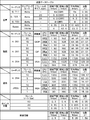
- FIG. 3 is a schematic diagram showing a data configuration of a transmission data table stored in an HDD 13;
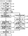
- FIG. It is a flowchart of the transmission main process performed when the communication apparatus 1 operate
- a communication device 1 that is an embodiment of a communication device according to the present invention and a band measurement system 100 including a plurality of communication devices 1 will be described with reference to the drawings.
- the drawings to be referred to are used for explaining technical features that can be adopted by the present invention.
- the configuration of the apparatus, the flowcharts of various processes, and the like described in the drawings are not intended to be limited to these, but are merely illustrative examples.
- the band measurement system 100 will be described. As shown in FIG. 1, the band measurement system 100 includes at least two communication devices 1. The communication device 1 is connected to another communication device 1 via the network 8. The communication device 1 communicates various data with other communication devices 1.
- the bandwidth measurement system 100 is a video conference system for users at a plurality of bases to hold a video conference.
- Each communication device 1 transmits and receives audio data and moving image data to each other, thereby sharing audio and video from a plurality of locations and realizing a video conference.
- each communication device 1 can also transmit and receive data of materials such as documents during a video conference. The user can proceed with the video conference while viewing the same material as other users.
- the communication device 1 may be any device that can execute data communication via the network 8.
- the communication device 1 may be a dedicated video conference terminal disposed at each site for performing a video conference, or may be a personal computer that performs various information processing.
- each communication device 1 packetizes audio data, moving image data, and the like, and transmits and receives the data while measuring the available bandwidth and determining whether the available bandwidth is secured (hereinafter collectively referred to as these).
- “Available bandwidth” refers to the maximum transmission rate at which the receiving communication device 1 can receive data at a transmission rate substantially equal to the transmission rate of data transmitted by the transmitting communication device 1.
- the “use band” is a band used by the transmission-side communication device 1 to transmit data. In order to compare the bandwidth and the transmission speed between the communication apparatuses 1, the bandwidth is represented by a transmission path capacity (bps).
- each communication device 1 controls the data transmission rate according to the measured bandwidth.
- the communication device 1 includes a CPU 10 that controls the communication device 1.
- a ROM 11, a RAM 12, a hard disk drive (hereinafter referred to as “HDD”) 13, and an input / output interface 19 are connected to the CPU 10 via a bus 18.
- the ROM 11 stores a program for operating the communication device 1, an initial value, and the like.
- the RAM 12 temporarily stores various information used in the control program.
- the HDD 13 is a non-volatile storage device that stores various information such as a transmission data table (see FIG. 2) to be described later and a control program. Instead of the HDD 13, a storage device such as an EEPROM or a memory card may be used.
- the input / output interface 19 is connected to an audio input processing unit 21, an audio output processing unit 22, a video input processing unit 23, a video output processing unit 24, an operation unit 25, and an external communication I / F 26.
- the voice input processing unit 21 processes input of voice data from the microphone 31 that inputs voice.
- the audio output processing unit 22 processes the operation of the speaker 32 that outputs audio.
- the video input processing unit 23 processes input of moving image data from the camera 33 that captures video.
- the video output processing unit 24 processes the operation of the display device 34 that displays video.
- the operation unit 25 is used for a user to input various instructions to the communication device 1.
- the operation unit 25 may be connected to the input / output interface 19 from the outside of the communication device 1.
- the external communication I / F 26 connects the communication device 1 to the network 8.
- the communication device 1 that transmits data packetizes the data to be transmitted into a plurality of packets.
- the transmission device transmits a plurality of packets continuously to another communication device 1 (hereinafter referred to as “reception device”) via the network 8. If the transmission rate (unit: bps) at the time of transmitting a packet is equal to or less than the usable bandwidth (unit: bps) between the transmission device and the reception device, the packet will not be congested (congested).
- the interval at which the receiving device receives a plurality of packets transmitted by the transmitting device is theoretically the same as the interval at which the transmitting device transmits a plurality of packets (transmission interval). Become. On the other hand, if the transmission rate is greater than the available bandwidth, the packet is congested and the reception interval is longer than the transmission interval.
- the transmission device When measuring the bandwidth, the transmission device transmits a plurality of packets while gradually increasing or decreasing the transmission interval.
- the transmission rate when a certain packet is transmitted is obtained by the following equation (1).
- Transmission rate (bps) Packet size (bit) / Time interval between previous packet transmission and current packet transmission (s) (1)
- the reception interval becomes longer than the transmission interval while the transmission rate is higher than the available bandwidth.
- the transmission interval becomes longer and the transmission rate becomes equal to or lower than the usable bandwidth, the reception interval and the transmission interval become the same. Therefore, the data transmission rate at the time when the value of “reception interval ⁇ transmission interval” changes can be measured as an available bandwidth.
- the bandwidth measurement system 100 the bandwidth is measured by the following procedure.
- the communication device 1 of the present embodiment is characterized in that the search range is limited according to the type of transmission data. As a result, the communication device 1 can prevent the available bandwidth from being measured wastefully when the available bandwidth is significantly larger than and significantly smaller than the usage bandwidth. Details of this will be described later.
- the search range is divided into one or a plurality of small sections.
- the transmitting apparatus transmits a packet group (hereinafter referred to as “stream”) composed of a plurality of packets for each divided small section.
- the stream is transmitted in order to determine whether or not there is a change point of the value of “reception interval ⁇ transmission interval” in the small section.
- the communication device 1 can obtain a measurement result that is more resistant to temporary abnormalities, and can accurately detect the time when the value of “reception interval ⁇ transmission interval” changes.
- the smaller the number of small sections to be divided the shorter the time required for the measurement process. Therefore, the communication device 1 can obtain the measurement result quickly.
- a stream corresponding to the search range is transmitted and received between the transmission device and the reception device.
- the communication device 1 determines a stream transmission condition for measuring a band in each small section.
- the transmission conditions include the number of packets constituting the stream (hereinafter referred to as “measurement packet number”), the packet size of each packet, and the transmission time from the previous packet transmission to the transmission of the next packet. Includes an interval.
- the transmission interval is determined so as to gradually increase, the band is searched in order from the upper limit value to the lower limit value of the search range.
- the transmission device generates and transmits a plurality of packets according to the determined transmission condition. Each packet includes time information for the receiving device to calculate the transmission interval.
- the bandwidth is measured from the difference between the reception interval and the transmission interval.
- the reception interval is calculated from the time when the receiving apparatus actually receives the packet.
- a transmission interval is calculated from the time information included in the received packet.
- the relationship between the transmission rate of data when a packet is transmitted and the reception rate (bps) when the packet is received is approximated by two straight lines by a linear regression method. As a result, a time point at which the value of “reception interval ⁇ transmission interval” changes is detected. If there is a change point, the data transmission rate at the change point is measured as an available bandwidth. If the change time does not exist and the value of the difference of “reception interval ⁇ transmission interval” becomes zero throughout the search range, it is determined that there is an available bandwidth in a range larger than the search range.
- the receiving apparatus notifies the transmitting apparatus of the maximum value within the search range as a provisional measurement result (the latest measurement result F shown in FIGS. 5 to 7).
- the communication device 1 can secure the use bandwidth if the use bandwidth used by the transmission device is smaller than the maximum value in the search range. Further, if there is no change time point and the value of the difference of “reception interval ⁇ transmission interval” becomes a positive value throughout the search range, it is determined that an available band exists in a range smaller than the search range.
- the receiving apparatus notifies the transmitting apparatus of the minimum value within the search range as a provisional measurement result F.
- the communication device 1 can measure the bandwidth while transmitting and receiving packets including voice data and the like. If the search range is set so that the search range includes the available bandwidth, the communication device 1 can measure the value of the available bandwidth while performing the video conference. However, the communication device 1 may only need to recognize whether or not the available bandwidth is larger than the available bandwidth (whether or not the available bandwidth is secured). For example, even when the use band and the available band fluctuate, problems such as transmission delay do not occur if the available band is larger than the maximum value of the use band (hereinafter referred to as “maximum use band”). Therefore, the communication device 1 does not need to grasp the value of the usable bandwidth.
- maximum use band the maximum value of the use band
- the communication device 1 can prevent an unnecessary load from being applied to the communication device 1 and the network 8 by setting an appropriate search range.
- the transmission data table is a table that stores information on the bandwidth used when the communication device 1 transmits transmission data for each type of transmission data.
- data that can be transmitted and received by the communication device 1 includes audio data, moving image data, material data, pointer position data, and control information.
- audio data is classified into six types according to the type of codec, the sampling rate, and the size of one frame.
- other data such as moving image data is also classified into one or more types.
- the communication device 1 transmits one or a plurality of types of data to the receiving device according to the performance of the receiving device, an instruction from the user, and the like.
- the left side from the center of FIG. 2 represents the type of data.
- Each data type is associated with information on the bandwidth used.
- the information on the bandwidth used consists of bandwidth lower limit, bandwidth upper limit, average bandwidth, and dispersion information.
- the information on the lower limit and the upper limit of the band is information indicating the lower limit and the upper limit of the use band used for transmitting data.
- Band lower limit and band upper limit information is determined in advance for each type of data.
- the communication device 1 can limit the search range by using the sum of the upper band limit values and the minimum band lower limit value for one or a plurality of data to be transmitted.
- “CBR” in FIG. 2 is an abbreviation for “Constant Bit Rate” and indicates data transmitted at a constant transmission rate.
- the average bandwidth is the average value of the bandwidth used when the communication device 1 actually transmits data.
- the communication device 1 obtains the use band value for each data, calculates the average value, and updates the average band value in the transmission data table.
- the distribution is a distribution of a use band when the communication apparatus 1 actually transmits data.
- the communication device 1 calculates the variance from the use band value acquired during data transmission and stores it in the transmission data table.
- the communication device 1 can limit the search range based on the average bandwidth and the variance.
- a transmission main process and a packet transmission process executed when the communication apparatus 1 operates as a transmission apparatus that transmits a measurement packet for measuring a band will be described with reference to FIGS.
- the transmission main process and the packet transmission process are executed by the CPU 10 of the transmission apparatus according to a program stored in the HDD 13.
- the transmission main process is executed when an instruction to transmit / receive data to / from the receiving device is input to the communication device 1.
- the packet transmission process is executed in parallel with the transmission main process on condition that the bandwidth measurement start process is performed in the transmission main process.
- an application for executing a video conference is activated (S1).
- a call is connected to the receiving device, and a packet can be transmitted to and received from the receiving device (S2).
- a negotiation process is performed (S3). In the negotiation process, after the type of data to be transmitted / received to / from the receiving apparatus is determined, a setting for limiting the search range is performed, and a process of starting the band measurement is performed. Details of this will be described later with reference to FIG.
- S9 it is determined whether an instruction to add a data type to be transmitted is input. Specifically, in the present embodiment, it is determined whether or not an instruction to share material data of the transmission device is input during a video conference using audio and moving images. If the instruction to add the data type has not been input (S9: NO), the process returns to S4, and the processes of S4 to S9 are repeated.
- an offer / answer model using a session description protocol is used when determining the type of data transmitted / received between a transmitting device and a receiving device.
- SDP session description protocol
- an offer indicating a list of data types that can be transmitted by the transmitting device and data types that can be received is transmitted to the receiving device (S31).
- An answer indicating a data type that can be transmitted by the receiving device and a list of data types that can be received is received from the receiving device (S32).
- the type of transmission data to be transmitted to the receiving device is determined, and a list of the determined types of transmission data is acquired from the transmission data table (see FIG. 2) (S33).
- the communication device 1 of the present embodiment can use two methods as methods for limiting the search range.
- One method is a method using the maximum usage band and the minimum usage band.
- Another method is to use the average and variance of the bandwidth used.
- the user sets in advance which of the two methods is to be used by operating the operation unit 25.
- S34 it is determined which method is set to be used.
- the transmission apparatus sets the search range so that the center of the search range does not exceed Omax. As a result, the search range is limited.
- the minimum value of the lower band limits for each data type is set to the lower limit value Omin where the center of the search range is located (S37).
- the values of Omin and Omax are set so that approximately 99.7% of the used bandwidth falls within the range of Omin to Omax. Can do.
- the range from Omin to Omax can be set to an appropriate range in which the use band falls within a high probability. If the available bandwidth is equal to or less than Omax, the communication device 1 can use the available bandwidth even when the measured bandwidth value is only greater than Omax (when the available bandwidth value is not measured). It can be grasped that it is secured.
- the value applied to the total variance “B” is not limited to 3.
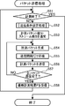
- the transmission apparatus executes the packet transmission process in parallel with the transmission main process. As shown in FIG. 5, first, it is determined whether or not processing for ending the bandwidth measurement (S21, see FIG. 3) or processing for suspending (see S11, FIG. 3) has been performed (S51). If the process for terminating or suspending is not performed (S51: NO), the transmission condition setting process is performed (S52).
- the transmission condition setting process when the transmission condition setting process is started, it is determined whether or not it is the first band measurement process performed with the receiving apparatus (S61). In other words, it is determined whether the band between the receiving apparatus and the receiver has not been measured yet. If it is the first measurement process (S61: YES), the initial search range, the packet size, the number of streams S, and the number N of measured packets are set to predetermined values (S62). In the present embodiment, a default value is used as the predetermined value. However, the method of setting these values can be changed. For example, the initial search range may be set based on a band measured by another band measuring method.
- the search range in the next band measurement process (hereinafter referred to as “next search range”) is determined according to the latest measurement result value F notified from the receiving device. ) Is set. Although details will be described later, the band between the transmission device and the reception device is measured by the reception device. The transmission device grasps the bandwidth by receiving the measurement result from the reception device. If the latest measurement result F is Omin or more and Omax or less, the transmission device uses the latest measurement result F or the previously set search range (the search range set for measuring the latest measurement result F). Set the next search range. As a result, the transmission apparatus can set an appropriate search range for measuring the available bandwidth as the next search range. This process is described in the aforementioned literature. On the other hand, if the latest measurement result F is not in the range from Omin to Omax, the center position of the next search range is limited. As a result, it is possible to prevent the usable bandwidth from being measured wastefully. Details will be described below.
- the transmission device limits the search range by limiting the center position of the search range in S63 to S66.
- the value of the latest measurement result F is greater than or equal to Omin (S65: NO)
- the search range width D is calculated from the accumulated band measurement results, and the next search range is set (S71). That is, if the value at which the center of the next search range is located is C, the minimum value of the next search range is “CD ⁇ 2” and the maximum value is “C + D / 2”.
- the width D of the next search range is calculated by the following equation (2), similarly to the method described in the above-described document.
- ⁇ is a variance of one or more accumulated measurement results
- ⁇ is a square root of the number of one or more accumulated measurement results.
- Dmin is adopted as the width of the next search range. Thereafter, the process proceeds to S72.
- the search range is expanded, and the expanded search range is set as the next search range (S69).
- the process proceeds to S72. Specifically, as described above, when the available bandwidth is larger than the upper limit value of the previous search range, the upper limit value of the previous search range is provisionally set as the latest measurement result F. If the value of the latest measurement result F is the upper limit value of the previous search range notified as a provisional measurement result, the value of the maximum value Bu ′ of the next search range is the maximum value of the previous search range.
- the next search range is expanded to a search range for measuring up to a band larger than the previous time.
- the value of Bl is used as it is for the value of the minimum value Bl ′ of the next search range.
- the value of the minimum value Bl ′ of the next search range is calculated by the following equation (4).
- the next search range is expanded to a search range for measuring up to a band smaller than the previous time. Note that the value of the previous maximum value Bu is used as it is as the value of the maximum value Bu ′ of the next search range.
- the transmission interval for searching for one search band value Ki (the elapsed time since the transmission of the previous measurement packet) is obtained by the following equation (5), where Ps is the packet size (bit) of the measurement packet. . Thereafter, the process returns to the packet transmission process.
- the transmission condition setting process (S52) ends, the number of measurement packets N and the number of streams S are notified to the receiving device (S53).
- a measurement packet having the set packet size Ps is generated (S54).
- the measurement packet includes transmission data such as voice data, packet number information, and time information for calculating a transmission interval between the previously transmitted measurement packet.
- the packet number is a number indicating the order of each measurement packet in the measurement stream, and a serial number is used.
- it waits for the set transmission interval (S55).
- the generated measurement packet is transmitted to the receiving device (S56). It is determined whether or not all N ⁇ S measurement packets have been transmitted (S57).
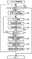
- the packet reception process is executed when the communication device 1 operates as a receiving device that receives a measurement packet and measures a bandwidth. That is, the communication device 1 can operate as both a transmission device and a reception device.
- the packet receiving process is executed by the CPU 10 of the receiving apparatus according to a program stored in the HDD 13 when an instruction to transmit / receive data to / from the transmitting apparatus is input.
- a difference value between the reception interval and the transmission interval is calculated for each packet number (S87).
- the bandwidth is measured from the time when the calculated difference value changes (S88). Specifically, first, a time point at which the difference value of “reception interval ⁇ transmission interval” starts to change is detected by the linear regression method. When the change time point is detected, the search band value Ki at the change time point is used as the available band measurement result F. When the change time point is not detected, it is determined whether or not the difference value is approximately “0” in the entire search range.
- the transmission apparatus does not necessarily need to recognize the value of an available band. This is because if the transmitting device recognizes that the available bandwidth is larger than the maximum value of the search range, it can determine that the available bandwidth can be secured without recognizing the available bandwidth value. If the difference between the “reception interval ⁇ transmission interval” is almost positive in the entire search range, it is determined that the available bandwidth is below the search range, and the minimum value of the search range is provisional. Measurement result F is assumed. When the bandwidth is measured, the latest measurement result F is transmitted to the transmission device (S89), and the process returns to the determination of S81. If there is an instruction to end the bandwidth measurement (S81: YES), the packet reception process ends.
- the communication device 1 When the communication device 1 operates as a transmission device, the communication device 1 sets the upper limit value Omax and the lower limit value Omin at which the center of the search range is located with reference to the information in the transmission data table (see FIG. 2). To do. In a time zone other than the time zone W shown in FIG. 8, the latest measurement result of the band is Omin or more and Omax or less. Therefore, the communication device 1 sets the value of the latest measurement result as the center position of the next search range without limiting the center position of the search range in a time zone other than the time zone W. As a result, the transmission device can set the search range in the vicinity of the value of the latest measurement result. Therefore, the receiving device can efficiently and accurately measure the value of the usable bandwidth.
- the communication device 1 sets the center position of the next search range as Omax set as the upper limit value.
- the communication device 1 can efficiently measure the bandwidth according to the data to be transmitted. In other words, the communication device 1 can easily grasp that the use band is secured.
- the communication device 1 when the type of data to be transmitted is changed, the communication device 1 resets the value of Omax and the value of Omin. Therefore, even when the type of data to be transmitted is changed, the communication device 1 can appropriately limit the search range according to the changed type of data.
- the communication device 1 limits the search range based on the type of transmission data. Therefore, the communication device 1 can set an appropriate search range according to the type of transmission data. Specifically, the communication device 1 sets the center of the search range to be equal to or less than the maximum usable bandwidth, so that the usable bandwidth is significantly larger than the maximum usable bandwidth (the usable bandwidth is large enough to ignore the possibility that the usable bandwidth exceeds the usable bandwidth). ) Can be efficiently prevented from being wasted. Further, the communication device 1 can also limit the search range using the average and variance of the used bandwidth. The communication device 1 can effectively prevent the available bandwidth from being measured wastefully by a statistical method using average and variance.
- the communication device 1 is usable if it is a range that is larger by D / 2 (D is the width of the search range) than the value of the maximum available bandwidth or the value of “H + 3B” calculated using the average and variance.
- the bandwidth value can be measured. Therefore, even if the usage bandwidth is temporarily increased, if the increase in the usage bandwidth is within D / 2, whether or not the increased usage bandwidth can be secured has already been measured. Can be used to quickly make decisions.
- the communication device 1 can appropriately limit the search range according to the changed type of transmission data by setting the value of Omax every time the type of data to be transmitted is changed.
- the communication device 1 sets a transmission interval, a measurement packet number N, and a packet size Ps for measuring a bandwidth within the set search range.
- a packet is generated according to the set condition and transmitted. As a result, the communication device 1 can cause the receiving device to accurately measure the band within the set search range.
- the maximum use band is set not to the upper limit value Omax where the center of the search range is located but to the upper limit value Rmax where the maximum value of the search range is located.
- the minimum value of the use band is set not to the lower limit value Omin where the center of the search range is located, but to the lower limit value Rmin where the minimum value of the search range is located.
- the value “H + 3B” is set to Rmax
- the value “H-3B” is set to Rmin.
- the next search range is reset so that the maximum value of the search range matches Rmax without changing the width of the search range ( S106). If the maximum value is less than or equal to Rmax (S105: NO), it is determined whether or not the minimum value of the temporarily set search range is smaller than Rmin (S107). When the minimum value is smaller than Rmin (S107: YES), the next search range is reset so that the minimum value of the search range matches Rmin without changing the width of the search range ( S108). If the minimum value is equal to or greater than Rmin (S107: NO), the temporarily set search range is directly adopted as the next search range, and the process proceeds to S72.
- the communication device 1 may limit the upper limit value where the maximum value of the search range is located, using the maximum available bandwidth or the variance.
- the communication device 1 can further reduce the possibility of measuring an available bandwidth that is larger than the available bandwidth by setting an upper limit value where the maximum value of the search range is located. Therefore, the communication device 1 can efficiently measure the bandwidth according to the data to be transmitted.
- the communication device 1 uses a part of the band measurement method described in the above-described literature.
- the present invention can be applied even when a method other than the bandwidth measurement method described in the above-described document is used.
- a method of measuring a band from a transmission interval and a reception interval of two packets for example, a method of measuring a band from a transmission interval and a reception interval of two packets (so-called “packet pair method”) and a method of measuring a band from a transmission interval and a reception interval of three packets (a so-called “train base method”).
- the present invention can also be applied to other systems such as “)”.
- any method other than the method described in the above-described document can be used as long as the bandwidth is measured while transmitting and receiving media data using a transmission interval and a reception interval of a plurality of packets. Applicable.
- the communication device 1 calculates “H + 3B” and “H-3B” from the average use band H and the variance B when the search range is limited using a statistical method.
- the calculated values are set to Omax and Omin values or Rmax and Rmin values.
- the communication apparatus may calculate the standard deviation of the value of the usage band and set the sum of the calculated standard deviation and the average usage band to the value of Omax or Rmax.
- the communication apparatus may set the difference between the average usage band and the standard deviation of the usage band value to the value of Omin or Rmin.
- the communication device can efficiently limit the search range by using the standard deviation. Further, as described above, when the variance B is used, the value applied to the variance B is not limited to “3”.
- Bandwidth measurement in the present invention includes not only measuring the available bandwidth, but also determining whether a bandwidth suitable for communication is secured.
- the “bandwidth suitable for communication” is a bandwidth value within which the packet transmission time delay falls within an allowable range.
- the “band suitable for communication” is preferably a value equal to or less than an available band that does not cause a delay in transmission time. However, even if the value is larger than the usable bandwidth, a certain value that can tolerate transmission time delay may be set as a “band suitable for communication”.
- the receiving device measures the band and notifies only the measurement result to the transmitting device.
- the transmission device and other servers may measure the bandwidth. For example, when the transmission device measures a band, the reception device calculates a reception interval and a transmission interval, and notifies the transmission device of the calculated reception interval and transmission interval.
- the transmitting device may detect the time point when the difference value of “reception interval ⁇ transmission interval” changes using the reception interval and transmission interval notified from the receiving device, and measure the bandwidth.
- the amount of data transmitted and received between the receiving device and the transmitting device is larger than when only the measurement result is notified from the receiving device to the transmitting device.
Landscapes
- Engineering & Computer Science (AREA)
- Computer Networks & Wireless Communication (AREA)
- Signal Processing (AREA)
- Health & Medical Sciences (AREA)
- Cardiology (AREA)
- General Health & Medical Sciences (AREA)
- Environmental & Geological Engineering (AREA)
- Data Exchanges In Wide-Area Networks (AREA)
- Maintenance And Management Of Digital Transmission (AREA)
- Telephonic Communication Services (AREA)
Abstract
通信装置およびネットワークに不要な負荷をかけることなく、送信するデータに応じて効率よく帯域を計測できるようにデータを通信することができる通信装置、通信方法、および通信プログラムを提供する。通信装置は、パケット化して送信するデータである送信データについての情報を参照することで、送信データの種別を取得する(S33)。通信装置は、取得した送信データの種別に応じて、複数のパケットによる帯域の計測対象範囲である探索範囲を制限する(S34~S41)。通信装置は、制限に従って探索範囲を設定する。通信装置は、設定した探索範囲内で帯域を計測するための複数のパケットを生成し、受信装置に送信する。
Description
本発明は、ネットワークを介してデータ通信を行う場合に、帯域を計測できるようにデータ通信を行う通信装置、通信方法、および通信プログラムに関する。
インターネット等のネットワークを介して通信装置がデータを送受信する場合、通信装置は、帯域(帯域幅:Available Bandwidth)に適した伝送速度でデータを送受信する必要がある。ネットワーク上で通信装置が単位時間当たりに伝送できるデータ容量である帯域(単位:bps)は、地域、プロバイダ、時間帯等の状況によって変動する。従って、データを送信する通信装置は、変動する帯域に合わせて、ネットワーク上に単位時間当たりに伝送するデータ容量(単位:bps)を制御することが望ましい。データの伝送速度が帯域以下であれば、データの輻輳、パケットロス等の問題が生じる可能性は低くなる。
非特許文献1は、音声データ等のメディアデータの送受信を行いながら、変動する帯域を計測するための計測方式を開示している。非特許文献1が開示している計測方式では、まず、送信側の通信装置は、帯域の計測対象範囲である探索範囲を設定する。設定した探索範囲内の帯域を計測するための、複数のパケットの送信条件を設定する。次いで、送信側の通信装置は、受信側の通信装置にパケットの送信間隔を算出させるための時間情報を含んだ複数のパケットを、送信間隔を変更しながら連続して送信する。受信側の通信装置は、パケットの受信間隔を記録する。その後、パケット内の時間情報によって算出されるパケットの送信間隔と、受信側の通信装置で記録された受信間隔との差分の値が算出される。算出された複数の差分の値の変化傾向から、現在の帯域が計測される。1回の帯域の計測が終了すると、過去の計測結果に基づいて次の帯域の探索範囲が設定され、次の計測処理が行われる。
津川知朗、CaoLe Thanh Man、長谷川剛、村田正幸、「インラインネットワーク計測手法ImTCPおよびその応用手法の実装および性能評価」、電子情報通信学会技術研究報告(IN2005-120)、p.79-84、2005年12月
非特許文献1が開示している計測方式では、通信装置が利用する帯域(以下、「利用帯域」という。)の大きさに関わらず、ネットワーク上でデータを通信できる帯域(以下、「可用帯域」という。)が計測される。従って、従来の計測方式では、例えば可用帯域に比べて利用帯域が小さく、利用帯域が可用帯域を上回る可能性がない場合でも、可用帯域を計測するために、データの伝送速度が大きくされる。その結果、通信装置およびネットワークに不要な負荷がかかるという問題点があった。
本発明は、通信装置およびネットワークに不要な負荷をかけることなく、送信するデータに応じて効率よく帯域を計測できるようにデータを通信することができる通信装置、通信方法、および通信プログラムを提供することを目的とする。
本発明の第一の態様に係る通信装置は、連続して送信される複数のパケットの各々の送信処理を行う間隔である送信間隔と、ネットワークを経由して受信された前記複数のパケットの受信間隔とに基づいて帯域を計測できるように、パケットの通信を行う通信装置であって、パケット化して送信するデータである送信データについての情報を参照することで、前記送信データの種別を取得する種別取得手段と、前記種別取得手段によって取得された前記送信データの種別に応じて、前記複数のパケットによる帯域の計測対象範囲である探索範囲を制限する範囲制限手段と、前記範囲制限手段による制限に従って前記探索範囲を設定する範囲設定手段と、前記範囲設定手段によって設定された前記探索範囲内で帯域を計測するための前記複数のパケットを生成して送信するパケット処理手段とを備えている。
第一の態様に係る通信装置は、送信データの種別に基づいて、帯域の計測対象範囲である探索範囲を制限する。従って、通信装置は、送信データの種別に応じた適切な探索範囲を設定することができる。可用帯域の計測が不要な場合には、可用帯域が無駄に計測される可能性が低下する。その結果、通信装置は、通信装置自身およびネットワークに不要な負荷をかけることなく、送信データに応じて帯域の計測を適切に実行できるように、データを通信することができる。
前記範囲制限手段は、前記送信データについて、前記種別取得手段によって取得された種別毎に、通信装置が前記種別の送信データを送信するために利用する可能性のある最大の帯域を取得し、取得した種別毎の帯域の和を算出することで、前記送信データを送信するために利用される最大の帯域である最大利用帯域を算出する最大値算出手段と、前記最大値算出手段によって算出された前記最大利用帯域を前記探索範囲の中心が位置する上限の値に設定することで、前記探索範囲を制限する、または、前記最大利用帯域を、前記探索範囲中の最大値が位置する上限の値に設定することで、前記探索範囲を制限する第一上限設定手段を備えてもよい。通信装置は、探索範囲の中心または最大値を、送信データを送信するために利用する最大利用帯域以下とすることで、計測する必要のない可用帯域が無駄に計測される可能性を低下させることができる。従って、通信装置は、送信データに適した帯域の計測を実行できるようにデータを通信することができる。
前記範囲制限手段は、前記送信データについて、前記種別取得手段によって取得された種別毎に、利用される帯域の平均値を取得し、取得した種別毎の平均値の和を算出することで、前記送信データを送信するために利用される帯域の平均値である平均利用帯域を算出する平均算出手段と、前記送信データについて、前記種別取得手段によって取得された種別毎に、利用される帯域の分散を取得し、取得した種別毎の分散の和を算出することで、前記送信データを送信するために利用される帯域の分散を算出する分散算出手段と、前記分散算出手段によって算出された分散の平方根である標準偏差、または前記分散にN(N>0)をかけた値と、前記平均算出手段によって算出された前記平均利用帯域との和を前記探索範囲の基準値として算出する基準値算出手段と、前記基準値算出手段によって算出された前記基準値を、前記探索範囲の中心が位置する上限の値に設定することで、前記探索範囲を制限する、または、前記基準値を前記探索範囲中の最大値が位置する上限の値に設定することで、前記探索範囲を制限する第二上限設定手段を備えてもよい。通信装置は、利用帯域の平均および分散を用いて探索範囲を制限することで、計測する必要のない可用帯域が無駄に計測される可能性を、統計的手法を用いて効果的に低下させることができる。利用帯域が可用帯域よりも大きくなる可能性が無視できる程度に、利用帯域が可用帯域よりも小さければ、可用帯域が無駄に計測される可能性は低くなる。通信装置は、利用帯域が可用帯域に収まっていることを容易に把握することができる。
前記通信装置は、前回送信された前記複数のパケットによって計測された帯域の値である最新計測結果を取得する結果取得手段と、前記結果取得手段によって取得された前記最新計測結果が、前記範囲制限手段によって設定されている前記上限の値よりも大きいか否かを判断する結果判断手段とをさらに備えてもよい。前記範囲設定手段は、前記結果判断手段によって前記最新計測結果が前記上限の値よりも大きいと判断された場合に、前記範囲制限手段によって設定されている前記上限の値を前記探索範囲の中心の値として前記探索範囲を設定するとよい。通信装置は、設定した上限の値よりも最新計測結果が大きければ、設定した上限の値を探索範囲の中心の値とすることで、計測する必要のない可用帯域を不要に測定することを容易に防止することができる。
前記通信装置は、前記送信データの種別が変更されたか否かを判断する変更判断手段をさらに備えてもよい。前記範囲制限手段は、前記変更判断手段によって前記送信データの種別が変更されたと判断される毎に前記上限の値を設定するとよい。通信装置は、送信データの種別が変更される毎に、変更された送信データの種別に応じて適切に探索範囲を制限することができる。
前記パケット処理手段は、前記範囲設定手段によって設定された探索範囲内で帯域を計測するための、前記複数のパケットの前記送信間隔と、前記複数のパケットを構成するパケット数と、前記複数のパケットを構成する各パケットのパケットサイズとを設定する送信条件設定手段と、前記送信条件設定手段によって設定されたパケットサイズで前記送信データをパケット化し、且つ前記送信間隔を割り出すための時間情報を各パケットに含めることで、前記送信条件設定手段によって設定されたパケット数の前記複数のパケットを生成する生成手段と、前記生成手段によって生成された前記複数のパケットを、前記送信条件設定手段によって設定された前記送信間隔で順次送信する送信手段とを備えてもよい。通信装置は、設定した探索範囲内で帯域を計測するための送信間隔、パケット数、およびパケットサイズを設定する。設定した条件に応じてパケットを生成し、送信する。その結果、通信装置は、設定した探索範囲内の帯域を的確に計測することができる。
本発明の第二の態様に係る通信方法は、連続して送信される複数のパケットの各々の送信処理を行う間隔である送信間隔と、ネットワークを経由して受信された前記複数のパケットの受信間隔とに基づいて帯域を計測できるように、パケットの通信を行う通信装置によって行われる通信方法であって、パケット化して送信するデータである送信データについての情報を参照することで、前記送信データの種別を取得する種別取得ステップと、前記種別取得ステップによって取得された前記送信データの種別に応じて、前記複数のパケットによる帯域の計測対象範囲である探索範囲を制限する範囲制限ステップと、前記範囲制限ステップによる制限に従って前記探索範囲を設定する範囲設定ステップと、前記範囲設定ステップによって設定された前記探索範囲内で帯域を計測するための前記複数のパケットを生成して送信するパケット処理ステップとを備えている。
第二の態様に係る通信方法によると、送信データの種別に基づいて、帯域の計測対象範囲である探索範囲が制限される。従って、通信装置は、送信データの種別に応じた適切な探索範囲を設定することができる。可用帯域の計測が不要な場合には、可用帯域が無駄に計測される可能性が低下する。その結果、通信装置は、通信装置自身およびネットワークに不要な負荷をかけることなく、送信データに応じて帯域の計測を適切に実行できるように、データを通信することができる。
本発明の第三の態様に係る通信プログラムは、連続して送信される複数のパケットの各々の送信処理を行う間隔である送信間隔と、ネットワークを経由して受信された前記複数のパケットの受信間隔とに基づいて帯域を計測できるように、パケットの通信を行う通信装置の動作を制御する通信プログラムであって、コンピュータに、パケット化して送信するデータである送信データについての情報を参照することで、前記送信データの種別を取得する種別取得ステップと、前記種別取得ステップによって取得された前記送信データの種別に応じて、前記複数のパケットによる帯域の計測対象範囲である探索範囲を制限する範囲制限ステップと、前記範囲制限ステップによる制限に従って前記探索範囲を設定する範囲設定ステップと、前記範囲設定ステップによって設定された前記探索範囲内で帯域を計測するための前記複数のパケットを生成して送信するパケット処理ステップとを実行させることを特徴とする。
第三の態様に係る通信プログラムによると、送信データの種別に基づいて、帯域の計測対象範囲である探索範囲が制限される。従って、通信装置は、送信データの種別に応じた適切な探索範囲を設定することができる。可用帯域の計測が不要な場合には、可用帯域が無駄に計測される可能性が低下する。その結果、通信装置は、通信装置自身およびネットワークに不要な負荷をかけることなく、送信データに応じて帯域の計測を適切に実行できるように、データを通信することができる。
以下、本発明の通信装置を具現化した一実施の形態である通信装置1、および複数の通信装置1を備えた帯域計測システム100について、図面を参照して説明する。参照する図面は、本発明が採用し得る技術的特徴を説明するために用いられるものである。図面に記載されている装置の構成、各種処理のフローチャート等は、それのみに限定する趣旨ではなく、単なる説明例である。
帯域計測システム100について説明する。図1に示すように、帯域計測システム100は、少なくとも2つの通信装置1を備える。通信装置1は、ネットワーク8を介して他の通信装置1と接続する。通信装置1は、他の通信装置1との間で各種データの通信を行う。
本実施の形態の帯域計測システム100は、複数の拠点のユーザがテレビ会議を行うためのテレビ会議システムである。各通信装置1は、音声データおよび動画データを互いに送受信することで、複数の拠点の音声および映像を共有し、テレビ会議を実現する。さらに、各通信装置1は、文書等の資料のデータをテレビ会議中に送受信することもできる。ユーザは、他のユーザと同じ資料を見ながらテレビ会議を進行させることができる。通信装置1は、ネットワーク8を介したデータ通信を実行できるものであればよい。具体的には、通信装置1は、テレビ会議を実行するために各拠点に配置される専用のテレビ会議端末であってもよいし、種々の情報処理を行うパーソナルコンピュータであってもよい。
帯域計測システム100では、各通信装置1は、音声データおよび動画データ等をパケット化して送受信しつつ、可用帯域の計測、および利用帯域が確保されているか否かの判定(以下、これらをまとめて「帯域の計測」という。)を行うことができる。「可用帯域」とは、送信側の通信装置1が送信するデータの伝送速度とほぼ等しい伝送速度で受信側の通信装置1がデータを受信できる最大の伝送速度をいう。「利用帯域」とは、送信側の通信装置1がデータを送信するために利用する帯域である。帯域と、各通信装置1間の伝送速度とを比較するため、帯域を伝送路容量(bps)で表す。可用帯域を越える伝送速度でパケットが送信されると、パケットロス、輻輳による送信遅延等が生じる。一方、通信装置1がデータの伝送速度を低くしすぎると、帯域を十分に活用することができず、効率が悪い。従って、各通信装置1は、計測された帯域に合わせてデータの伝送速度を制御する。
通信装置1の電気的構成について説明する。図1に示すように、通信装置1は、通信装置1の制御を司るCPU10を備えている。CPU10には、ROM11、RAM12、ハードディスクドライブ(以下、「HDD」という。)13、および入出力インターフェース19が、バス18を介して接続されている。
ROM11は、通信装置1を動作させるためのプログラムおよび初期値等を記憶している。RAM12は、制御プログラムで使用される各種の情報を一時的に記憶する。HDD13は、後述する送信データテーブル(図2参照)、および制御プログラム等の各種の情報を記憶する不揮発性の記憶装置である。HDD13の代わりに、EEPROMまたはメモリカード等の記憶装置を用いてもよい。
入出力インターフェース19には、音声入力処理部21、音声出力処理部22、映像入力処理部23、映像出力処理部24、操作部25、および外部通信I/F26が接続されている。音声入力処理部21は、音声を入力するマイク31からの音声データの入力を処理する。音声出力処理部22は、音声を出力するスピーカ32の動作を処理する。映像入力処理部23は、映像を撮像するカメラ33からの動画データの入力を処理する。映像出力処理部24は、映像を表示する表示装置34の動作を処理する。操作部25は、ユーザが通信装置1に各種指示を入力するために用いられる。操作部25は、通信装置1の外部から、入出力インターフェース19へ接続されるものであってもよい。外部通信I/F26は、通信装置1をネットワーク8に接続する。
次に、本実施の形態の帯域計測システム100で用いられる帯域計測方式について、概略的に説明する。帯域計測システム100では、以下の文献に記載されている帯域計測方式が利用される。「津川知朗、CaoLe Thanh Man、長谷川剛、村田正幸、「インラインネットワーク計測手法ImTCPおよびその応用手法の実装および性能評価」、電子情報通信学会技術研究報告(IN2005-120)、p.79-84、2005年12月」
計測原理について説明する。帯域計測システム100では、データを送信する通信装置1(以下、「送信装置」という。)は、送信するデータを複数のパケットにパケット化する。送信装置は、複数のパケットを連続して他の通信装置1(以下、「受信装置」という。)にネットワーク8を介して送信する。パケットを送信する際の伝送速度(単位:bps)が、送信装置と受信装置との間の可用帯域(単位:bps)以下であれば、パケットは渋滞(輻輳)しない。パケットが渋滞しなければ、送信装置によって送信された複数のパケットを受信装置が受信する間隔(受信間隔)は、理論的に、送信装置が複数のパケットを送信する間隔(送信間隔)と同一となる。一方、伝送速度が可用帯域よりも大きければ、パケットは渋滞し、受信間隔は送信間隔よりも長くなる。
帯域を計測する場合、送信装置は、送信間隔を徐々に長くしながら、または徐々に短くしながら、複数のパケットを送信する。あるパケットが送信された場合の伝送速度は、以下の式(1)で求められる。
伝送速度(bps)=パケットサイズ(bit)/前回のパケット送信時と今回のパケット送信時との時間間隔(s)・・・・・(1)
送信間隔を徐々に長くしながら複数のパケットを送信すると、伝送速度が可用帯域よりも大きい間は、受信間隔が送信間隔よりも長くなる。しかし、送信間隔が長くなり、伝送速度が可用帯域以下となれば、受信間隔と送信間隔とが同一となる。よって、「受信間隔-送信間隔」の値が変化する時点のデータの伝送速度を、可用帯域として計測することができる。
計測手順の概略について説明する。帯域計測システム100では、以下の手順で帯域が計測される。
1.帯域の探索範囲を設定する。
その時点の可用帯域を計測できると予想される探索範囲を限定することで、効率よく可用帯域を計測することができる。さらに、本実施の形態の通信装置1は、送信データの種別に応じて探索範囲を制限する点に特徴を有する。その結果、通信装置1は、可用帯域が利用帯域よりも著しく大きい場合および著しく小さい場合に、可用帯域が無駄に計測されることを防止できる。この詳細については後述する。
その時点の可用帯域を計測できると予想される探索範囲を限定することで、効率よく可用帯域を計測することができる。さらに、本実施の形態の通信装置1は、送信データの種別に応じて探索範囲を制限する点に特徴を有する。その結果、通信装置1は、可用帯域が利用帯域よりも著しく大きい場合および著しく小さい場合に、可用帯域が無駄に計測されることを防止できる。この詳細については後述する。
2.探索範囲を1または複数の小区間に分割する。
送信装置は、帯域を計測する際、分割した小区間毎に、複数のパケットからなるパケット群(以下、「ストリーム」という。)を送信する。ストリームは、小区間内に「受信間隔-送信間隔」の値の変化時点が存在するか否かを判断するために送信される。通信装置1は、分割する小区間の数を多くする程、一時的な異常に対する耐性が高い計測結果を得ることができ、「受信間隔-送信間隔」の値の変化時点を正確に検出できる。分割する小区間の数が少ない程、計測処理に要する時間が短くなるため、通信装置1は計測結果を素早く得ることができる。
送信装置は、帯域を計測する際、分割した小区間毎に、複数のパケットからなるパケット群(以下、「ストリーム」という。)を送信する。ストリームは、小区間内に「受信間隔-送信間隔」の値の変化時点が存在するか否かを判断するために送信される。通信装置1は、分割する小区間の数を多くする程、一時的な異常に対する耐性が高い計測結果を得ることができ、「受信間隔-送信間隔」の値の変化時点を正確に検出できる。分割する小区間の数が少ない程、計測処理に要する時間が短くなるため、通信装置1は計測結果を素早く得ることができる。
3.探索範囲に対応するストリームを、送信装置と受信装置との間で送受信する。
通信装置1は、それぞれの小区間内で帯域を計測するためのストリームの送信条件を決定する。送信条件には、ストリームを構成するパケットの数(以下、「計測パケット数」という。)、各パケットのパケットサイズ、および、前回のパケット送信時から次のパケットを送信するまでの時間である送信間隔が含まれる。本実施の形態では、送信間隔は徐々に長くなるように決定されるため、探索範囲の上限値から下限値へ順に帯域が探索されることになる。次いで、送信装置は、決定した送信条件に従って複数のパケットを生成し、送信する。各パケットには、受信装置が送信間隔を算出するための時間情報が含まれる。
通信装置1は、それぞれの小区間内で帯域を計測するためのストリームの送信条件を決定する。送信条件には、ストリームを構成するパケットの数(以下、「計測パケット数」という。)、各パケットのパケットサイズ、および、前回のパケット送信時から次のパケットを送信するまでの時間である送信間隔が含まれる。本実施の形態では、送信間隔は徐々に長くなるように決定されるため、探索範囲の上限値から下限値へ順に帯域が探索されることになる。次いで、送信装置は、決定した送信条件に従って複数のパケットを生成し、送信する。各パケットには、受信装置が送信間隔を算出するための時間情報が含まれる。
4.受信間隔と送信間隔との差分から帯域を計測する。
受信装置がパケットを実際に受信した時刻から、受信間隔が算出される。受信されたパケットに含まれる時間情報から、送信間隔が算出される。パケットが送信された際のデータの伝送速度と、パケットが受信された際の受信レート(bps)との関係が、線形回帰法によって2本の直線で近似される。その結果、「受信間隔-送信間隔」の値の変化時点が検出される。変化時点が存在すれば、変化時点におけるデータの伝送速度が可用帯域として計測される。変化時点が存在せず、「受信間隔-送信間隔」の差分の値が探索範囲全体を通じてゼロとなれば、探索範囲よりも大きい範囲に可用帯域が存在すると判定される。本実施の形態では、受信装置は、探索範囲内の最大値を暫定的な計測結果(図5から図7に示す最新計測結果F)として送信装置に通知する。可用帯域が探索範囲よりも大きい範囲に存在する場合、送信装置が利用する利用帯域が、探索範囲内の最大値よりも小さければ、通信装置1は利用帯域を確保できる。また、変化時点が存在せず、「受信間隔-送信間隔」の差分の値が探索範囲全体を通じてプラスの値となれば、探索範囲よりも小さい範囲に可用帯域が存在すると判定される。受信装置は、探索範囲内の最小値を暫定的な計測結果Fとして送信装置に通知する。
受信装置がパケットを実際に受信した時刻から、受信間隔が算出される。受信されたパケットに含まれる時間情報から、送信間隔が算出される。パケットが送信された際のデータの伝送速度と、パケットが受信された際の受信レート(bps)との関係が、線形回帰法によって2本の直線で近似される。その結果、「受信間隔-送信間隔」の値の変化時点が検出される。変化時点が存在すれば、変化時点におけるデータの伝送速度が可用帯域として計測される。変化時点が存在せず、「受信間隔-送信間隔」の差分の値が探索範囲全体を通じてゼロとなれば、探索範囲よりも大きい範囲に可用帯域が存在すると判定される。本実施の形態では、受信装置は、探索範囲内の最大値を暫定的な計測結果(図5から図7に示す最新計測結果F)として送信装置に通知する。可用帯域が探索範囲よりも大きい範囲に存在する場合、送信装置が利用する利用帯域が、探索範囲内の最大値よりも小さければ、通信装置1は利用帯域を確保できる。また、変化時点が存在せず、「受信間隔-送信間隔」の差分の値が探索範囲全体を通じてプラスの値となれば、探索範囲よりも小さい範囲に可用帯域が存在すると判定される。受信装置は、探索範囲内の最小値を暫定的な計測結果Fとして送信装置に通知する。
5.上記1.へ戻り、探索範囲を再設定して再び帯域を計測する。
過去の計測結果に基づいて次の探索範囲を再設定することで、効率よく帯域を計測できる。
過去の計測結果に基づいて次の探索範囲を再設定することで、効率よく帯域を計測できる。
以上説明したように、パケットの送信間隔および受信間隔を利用して帯域を計測する方式では、通信装置1は、音声データ等を含んだパケットを送受信しながら帯域を計測することができる。通信装置1は、探索範囲内に可用帯域が含まれるように探索範囲を設定すれば、テレビ会議を実行しながら可用帯域の値を計測することができる。しかし、通信装置1は、利用帯域よりも可用帯域の方が大きいか否か(利用帯域が確保されているか否か)のみを認識すればよい場合がある。例えば、利用帯域および可用帯域が変動する場合でも、利用帯域の最大値(以下、「最大利用帯域」という。)よりも可用帯域の方が大きければ、送信遅延等の問題は生じない。よって、通信装置1は、可用帯域の値まで把握する必要はない。利用帯域が可用帯域を上回る可能性が無視できる程度に可用帯域の方が大きい場合に、可用帯域を計測するために大きい伝送速度でパケットが送信されると、通信装置1およびネットワーク8に不要な負荷がかかる。本実施の形態の通信装置1は、適切な探索範囲を設定することで、通信装置1およびネットワーク8に不要な負荷がかかることを防止することができる。以下、通信装置1が記憶するデータの構成、および通信装置1が行う処理について、詳細に説明する。
図2を参照して、送信装置のHDD13に記憶されている送信データテーブルのデータ構成について説明する。送信データテーブルは、通信装置1が送信データを送信する際の利用帯域の情報を、送信データの種別毎に記憶するテーブルである。まず、通信装置1が送受信できるデータには、音声データ、動画データ、資料データ、ポインタ位置データ、および制御情報がある。例えば、音声データは、コーデックの種類、サンプリングレート、および1フレームのサイズに応じて6つの種別に分類される。同様に、動画データ等の他のデータも、1または複数の種別に分類される。通信装置1は、受信装置の性能、ユーザからの指示等に応じて、1または複数の種別のデータのいずれかを受信装置へ送信する。図2の中央より左側は、データの種別を表している。
それぞれのデータの種別には、利用帯域の情報が対応付けられている。利用帯域の情報は、帯域下限、帯域上限、平均帯域、および分散の情報からなる。帯域下限および帯域上限の情報は、データを送信するために利用される利用帯域の下限および上限を示す情報である。帯域下限および帯域上限の情報は、データの種別毎にあらかじめ定められている。通信装置1は、送信する1または複数のデータについての帯域上限の値の和、および帯域下限の値の最小値を用いて、探索範囲を制限することができる。なお、図2における「CBR」は「Constant Bit Rate」の略であり、一定の伝送速度で送信されるデータであることを示す。
平均帯域は、通信装置1がデータを実際に送信した際の利用帯域の平均値である。通信装置1は、データの送信中に、データ毎に利用帯域の値を取得して平均値を算出し、送信データテーブルの平均帯域の値を更新する。分散は、通信装置1がデータを実際に送信した際の利用帯域の分散である。通信装置1は、データの送信中に取得した利用帯域の値から分散を算出し、送信データテーブルに記憶する。通信装置1は、平均帯域および分散に基づいて探索範囲を制限することができる。
図3から図6を参照して、帯域を計測するための計測パケットを送信する送信装置として通信装置1が動作する場合に実行される送信メイン処理およびパケット送信処理について説明する。送信メイン処理およびパケット送信処理は、HDD13に記憶されているプログラムに従って、送信装置のCPU10によって実行される。送信メイン処理は、受信装置との間でデータを送受信する指示が通信装置1に入力されることを契機として実行される。パケット送信処理は、送信メイン処理の中で帯域計測開始の処理が行われることを条件に、送信メイン処理と並行して実行される。
図3に示すように、送信メイン処理が開始されると、テレビ会議を実行するためのアプリケーションが起動される(S1)。受信装置との間で呼が接続され、パケットを受信装置との間で送受信することが可能な状態とされる(S2)。ネゴシエーション処理が行われる(S3)。ネゴシエーション処理では、受信装置との間で送受信されるデータの種別が決定された後に、探索範囲を制限するための設定が行われて、帯域の計測を開始する処理が行われる。この詳細については、図4を参照して後述する。
ネゴシエーション処理(S3)が終了すると、資料データ以外のデータ(主に音声データおよび動画データ)が受信装置との間で相互に送受信されて、映像通話が行われる(S4)。送信しているデータの伝送速度が、利用帯域としてデータの種別毎に取得される(S5)。取得された利用帯域の値および過去の利用帯域の値から、利用帯域の平均値である平均利用帯域と、利用帯域の値の分散とが、データの種別毎に算出される(S6)。算出結果が、送信データテーブル(図2参照)に更新される(S7)。受信装置との間の呼を切断する指示が入力されたか否かが判断される(S8)。切断する指示が入力されていなければ(S8:NO)、送信するデータ種別を追加する指示が入力されたか否かが判断される(S9)。具体的には、本実施の形態では、音声および動画を用いたテレビ会議中に、送信装置が有する資料データを共有する指示が入力されたか否かが判断される。データ種別を追加する指示が入力されていなければ(S9:NO)、処理はS4へ戻り、S4~S9の処理が繰り返し行われる。
データ種別を追加する指示が入力されると(S9:YES)、帯域の計測を中断させる処理が行われて(S11)、S3と同様のネゴシエーション処理が再度行われる(S12)。S12のネゴシエーション処理では、探索範囲を制限する処理が再び行われた後に、帯域の計測が再開される。資料データを含むデータが、受信装置との間で送受信される(S13)。送信しているデータの種別毎に、利用帯域が取得される(S14)。データの種別毎に、平均利用帯域および分散が算出され(S15)、算出結果が更新される(S16)。送信するデータの種別を減少させる指示、具体的には、資料データの共有を終了する指示が入力されたか否かが判断される(S17)。入力されていなければ(S17:NO)、処理はS13へ戻る。データの種別を減少させる指示が入力された場合には(S17:YES)、探索範囲を制限する設定が、データの種別が追加される前の設定に戻される(S18)。処理はS4へ戻る。
受信装置との間の呼を切断する指示が入力されると(S8:YES)、帯域の計測を終了させる処理が行われる(S21)。呼が切断され(S22)、アプリケーションを終了させる処理が行われて(S23)、送信メイン処理は終了する。
図4を参照して、送信メイン処理中に実行されるネゴシエーション処理について説明する。本実施の形態では、送信装置と受信装置との間で送受信されるデータの種別を決定する際に、セッション記述プロトコル(SDP)を用いたオファー・アンサーモデルが用いられる。まず、送信装置が送信可能なデータ種別、および受信可能なデータ種別の一覧を示すオファーが、受信装置に送信される(S31)。受信装置が送信可能なデータ種別、および受信可能なデータ種別の一覧を示すアンサーが、受信装置から受信される(S32)。受信装置に送信する送信データの種別が決定され、決定された送信データの種別の一覧が、送信データテーブル(図2参照)から取得される(S33)。
利用帯域の分散を使用して探索範囲を制限する設定となっているか否かが判断される(S34)。本実施の形態の通信装置1は、探索範囲を制限する方法として2つの方法を用いることができる。1つの方法は、最大利用帯域および最小利用帯域を使用する方法である。もう1つの方法は、利用帯域の平均および分散を使用する方法である。ユーザは、操作部25を操作することで、2つの方法のうちのいずれを使用させるかをあらかじめ設定しておく。S34では、いずれの方法を使用する設定となっているかが判断される。
分散を使用する設定となっていなければ(S34:NO)、最大利用帯域および最小利用帯域によって探索範囲を制限する処理が行われる。まず、送信データテーブルから取得されたデータから、各データの種別の帯域上限の値が加算されることで、最大利用帯域が算出される(S35)。算出された最大利用帯域の値が、探索範囲の中心が位置する上限の値Omaxに設定される(S36)。詳細は後述するが、送信装置は、送信条件設定処理(図6参照)において、探索範囲の中心がOmaxを超えないように、探索範囲を設定する。その結果、探索範囲が制限される。次いで、各データ種別についての帯域下限のうちの最小値が、探索範囲の中心が位置する下限の値Ominに設定される(S37)。
分散を使用する設定となっていれば(S34:YES)、平均利用帯域および分散によって探索範囲を制限する処理が行われる。まず、送信データテーブルから取得されたデータから、各データの種別の平均利用帯域が全て加算される(S38)。各データの種別の分散が全て加算される(S39)。平均利用帯域の合計値「H」と、分散の合計値「B」を3倍した値との和が算出される。算出された「H+3B」の値が、探索範囲の中心が位置する上限の値Omaxに設定される(S40)。「H-3B」の値が算出され、算出された値が、探索範囲の中心が位置する下限の値Ominに設定される(S41)。
統計学上、分散の合計値「B」を3倍した値を用いることで、利用帯域の約99.7%がOminからOmaxの範囲内に収まるように、OminおよびOmaxの値を設定することができる。その結果、OminからOmaxの範囲を、利用帯域が高い確率で収まる適切な範囲に設定することができる。利用帯域がOmax以下となれば、可用帯域の値がOmaxよりも大きいことのみが計測結果として得られた場合(可用帯域の値が計測されなかった場合)でも、通信装置1は、利用帯域が確保されていることを把握することができる。なお、分散の合計値「B」にかける値は3に限られない。OmaxおよびOminの設定が終了すると、帯域の計測が開始されて(S42)、処理は送信メイン処理へ戻る。
図5および図6を参照して、パケット送信処理について説明する。前述したように、送信装置は、送信メイン処理において帯域の計測を開始させる処理(S42、図4参照)が行われると、送信メイン処理と並行してパケット送信処理を実行する。図5に示すように、まず、帯域の計測を終了させる処理(S21、図3参照)、または中断させる処理(S11、図3参照)が行われたか否かが判断される(S51)。終了または中断させる処理が行われていなければ(S51:NO)、送信条件設定処理が行われる(S52)。
図6に示すように、送信条件設定処理が開始されると、受信装置との間で行われる初回の帯域の計測処理であるか否かが判断される(S61)。換言すると、受信装置との間の帯域が未だ1度も計測されていないか判断される。初回の計測処理であれば(S61:YES)、初期探索範囲、パケットサイズ、ストリーム数S、および計測パケット数Nが、所定の値に設定される(S62)。本実施の形態では、所定の値としてデフォルト値が用いられる。しかし、これらの値の設定方法は変更できる。例えば、他の帯域計測方法によって計測された帯域に基づいて初期探索範囲を設定してもよい。
初回の計測処理でなければ(S61:NO)、受信装置から通知された最新の計測結果の値Fに応じて、次回の帯域の計測処理における探索範囲(以下、「次回の探索範囲」という。)が設定される。詳細は後述するが、送信装置と受信装置との間の帯域は、受信装置によって計測される。送信装置は、計測結果を受信装置から受信することで、帯域を把握する。また、送信装置は、最新計測結果FがOmin以上Omax以下であれば、最新計測結果Fまたは前回設定した探索範囲(最新計測結果Fを計測するために設定されていた探索範囲)を利用して、次回の探索範囲を設定する。その結果、送信装置は、可用帯域を計測するための適切な探索範囲を次回の探索範囲として設定することができる。この処理は、前述した文献に記載されている。一方、最新計測結果FがOmin以上Omax以下の範囲になければ、次回の探索範囲の中心位置は制限される。その結果、可用帯域が無駄に計測されることが防止される。以下、詳細について説明する。
まず、最新計測結果Fの値が、設定されているOmaxの値よりも大きいか否かが判断される(S63)。Omaxよりも大きい場合には(S63:YES)、Omaxの値が、次回の探索範囲の中心が位置する値に決定される(S64)。最新計測結果Fの値がOmaxの値以下であれば(S63:NO)、Fの値がOminよりも小さいか否かが判断される(S65)。Ominよりも小さい場合には(S65:YES)、Ominの値が、次回の探索範囲の中心が位置する値に決定される(S66)。つまり、送信装置は、探索範囲の中心位置をS63~S66で制限することで、探索範囲を制限する。
最新計測結果Fの値がOmin以上であれば(S65:NO)、前回設定された探索範囲内にFの値が存在するか否かが判断される(S67)。Fの値が前回の探索範囲内(探索範囲の上限値および下限値を除く)にあれば(S67:YES)、最新計測結果Fの値が、次回の探索範囲の中心が位置する値に決定される(S68)。
次回の探索範囲の中心が位置する値が決定されると、蓄積された帯域の計測結果から探索範囲の幅Dが算出されて、次回の探索範囲が設定される(S71)。つまり、次回の探索範囲の中心が位置する値をCとすると、次回の探索範囲の最小値は「C-D/2」、最大値は「C+D/2」とされる。次回の探索範囲の幅Dは、前述した文献に記載されている方法と同様に、以下の式(2)によって算出される。式(2)におけるαは、蓄積された1または複数の計測結果の分散、βは、蓄積された1または複数の計測結果の個数の平方根である。
D=2×1.96×α/β・・・・・(2)
なお、計測結果が安定し、算出されたDの値があらかじめ定められた最小幅Dminよりも小さくなれば、Dminが次回の探索範囲の幅として採用される。その後、処理はS72へ移行する。
一方、最新計測結果Fの値がOmin≦F≦Omaxの範囲内、且つ前回の探索範囲外にあれば(S67:NO)、前回の探索範囲の最大値および最小値のいずれか一方が変更されることで探索範囲が拡大され、拡大された探索範囲が次回の探索範囲として設定される(S69)。処理はS72へ移行する。詳細には、前述したように、可用帯域が前回の探索範囲の上限値よりも大きい場合には、暫定的に前回の探索範囲の上限値が最新計測結果Fとされる。最新計測結果Fの値が、暫定的な計測結果として通知された前回の探索範囲の上限値である場合には、次回の探索範囲の最大値Bu´の値が、前回の探索範囲の最大値Buの値および最小値Blの値を用いて、以下の式(3)によって算出される。その結果、次回の探索範囲は、前回より大きい帯域まで計測する探索範囲に拡大される。なお、次回の探索範囲の最小値Bl´の値には、Blの値がそのまま用いられる。
Bu´=Bu+(Bu-Bl)/2・・・・・(3)
最新計測結果Fが、暫定的な計測結果として通知された前回の探索範囲の下限値であれば、次回の探索範囲の最小値Bl´の値が以下の式(4)によって算出される。その結果、次回の探索範囲は、前回より小さい帯域まで計測する探索範囲に拡大される。なお、次回の探索範囲の最大値Bu´の値には、前回の最大値Buの値がそのまま用いられる。
Bl´=Bl-(Bu-Bl)/2・・・・・(4)
次回の探索範囲が設定されると、設定された探索範囲が、ストリーム数であるS個の小区間に等分される(S72)。ストリーム数Sが「1」であれば、探索範囲全体がそのまま小区間とされる。次いで、分割された小区間のそれぞれが、各ストリームを構成する計測パケットの数Nで等分される(S73)。その結果、各計測パケットが探索する帯域の値である探索帯域値Ki(i=1,...,N-1)が一意に定まる。分割された帯域値である探索帯域値Ki(bps)を探索するための、各計測パケットの送信間隔が算出される(S74)。1つの探索帯域値Kiを探索するための送信間隔(前回の計測パケットを送信してからの経過時間)は、計測パケットのパケットサイズ(bit)をPsとして、以下の式(5)で求められる。その後、処理はパケット送信処理に戻る。
Ps/Ki・・・・・(5)
図5の説明に戻る。送信条件設定処理(S52)が終了すると、計測パケット数Nおよびストリーム数Sが受信装置に通知される(S53)。設定されているパケットサイズPsの計測パケットが生成される(S54)。計測パケットには、音声データ等の送信データと、パケット番号の情報と、前回送信された計測パケットとの間の送信間隔を算出するための時間情報とが含まれる。パケット番号は、計測ストリーム中の各計測パケットの順番を示す番号であり、通し番号が用いられる。次いで、設定されている送信間隔だけ待機される(S55)。待機時間が経過すると、生成された計測パケットが受信装置に送信される(S56)。N×S個の全ての計測パケットが送信されたか否かが判断され(S57)、送信されていなければ(S57:NO)、S54~S56の処理が繰り返し行われる。全ての計測パケットが送信された場合(S57:YES)、受信装置から最新計測結果Fが受信されて(S58)、処理はS51の判断へ戻る。帯域の計測を終了または中断させる処理が行われると(S51:YES)、パケット送信処理は終了する。
次に、図7を参照して、パケット受信処理について説明する。パケット受信処理は、計測パケットを受信して帯域を計測する受信装置として通信装置1が動作する場合に実行される。つまり、通信装置1は、送信装置としても受信装置としても動作できる。パケット受信処理は、送信装置との間でデータを送受信する指示が入力されると、HDD13に記憶されているプログラムに従って、受信装置のCPU10によって実行される。
パケット受信処理が開始されると、帯域を計測するためのパケットの受信を終了させる指示があったか否かが判断される(S81)。終了指示がなければ(S81:NO)、計測パケット数Nおよびストリーム数Sを示すデータが送信装置から受信されて、NおよびSの値が認識される(S82)。計測パケットが受信される(S83)。計測パケットが受信された時点の時刻が、受信時刻として取得される(S84)。受信された計測パケットに含まれるデータから、パケット番号が抽出され、且つ送信間隔が算出される(S85)。N×S個の全てのパケットの受信が完了したか否かが判断される(S86)。完了していなければ(S86:NO)、S83~S85の処理が繰り返し行われる。
全てのパケットの受信が完了すると(S86:YES)、受信間隔と送信間隔との差分の値が、パケット番号毎に算出される(S87)。算出された差分の値の変化時点から、帯域が計測される(S88)。詳細には、まず、線形回帰法によって、「受信間隔-送信間隔」の差分の値が変化し始める時点が検出される。変化時点が検出された場合には、変化時点の探索帯域値Kiが、可用帯域の計測結果Fとされる。変化時点が検出されなかった場合、探索範囲中の全範囲で差分の値が概ね「0」であったか否かが判断される。差分の値が概ね「0」であれば、可用帯域は探索範囲の最大値よりも大きいと判定され、探索範囲の最大値が暫定的な計測結果Fとされる。なお、送信装置が利用する利用帯域が、探索範囲の最大値よりも小さければ、送信装置は、必ずしも可用帯域の値まで認識する必要はない。送信装置は、可用帯域が探索範囲の最大値よりも大きいことを認識すれば、可用帯域の値を認識しなくても、利用帯域を確保できると判定できるためである。「受信間隔-送信間隔」の差分の値が、探索範囲中の全範囲で概ねプラスの値となっていれば、可用帯域は探索範囲を下回ると判定され、探索範囲の最小値が暫定的な計測結果Fとされる。帯域が計測されると、最新計測結果Fが送信装置に送信されて(S89)、処理はS81の判断へ戻る。帯域の計測を終了させる指示があれば(S81:YES)、パケット受信処理は終了する。
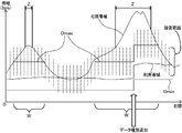
図8を参照して、本実施の形態の通信装置1が設定する探索範囲と、可用帯域および利用帯域との関係について説明する。通信装置1が送信装置として動作する場合、通信装置1は、送信データテーブル(図2参照)の情報を参照して、探索範囲の中心が位置する上限の値Omax、および下限の値Ominを設定する。図8に示す時間帯W以外の時間帯では、帯域の最新計測結果は、Omin以上、Omax以下となる。よって、通信装置1は、時間帯W以外の時間帯では、探索範囲の中心位置を制限することなく、最新計測結果の値を次回の探索範囲の中心位置とする。その結果、送信装置は、最新計測結果の値の近傍に探索範囲を設定することができる。よって、受信装置は、可用帯域の値を効率よく正確に計測することができる。
図8に示す時間帯Wでは、帯域の最新計測結果(可用帯域の値、または探索範囲の最大値)はOmaxよりも大きくなる。よって、通信装置1は、次回の探索範囲の中心位置を、上限の値として設定されているOmaxとする。その結果、図8に示す時間帯Zでは、利用帯域よりも著しく大きい可用帯域が無駄に計測されることが防止される。つまり、図8に示す時間帯Zでは、利用帯域が可用帯域を上回る可能性が無視できる程度に、可用帯域の方が大きい。従って、通信装置1は、利用帯域が確保できていることを認識できればよく、可用帯域の値まで計測する必要はない。可用帯域を無駄に計測しなければ、送信装置、受信装置、およびネットワーク8に不要な負荷がかかることはない。よって、通信装置1は、送信するデータに応じて、帯域を効率よく計測することができる。換言すると、通信装置1は、利用帯域が確保されていることを容易に把握することができる。
また、図8に示すように、送信するデータの種別が変更されると、通信装置1は、Omaxの値およびOminの値を再設定する。従って、通信装置1は、送信するデータの種別が変更された場合でも、変更されたデータの種別に応じて適切に探索範囲を制限することができる。
以上説明したように、本実施の形態に係る通信装置1は、送信データの種別に基づいて探索範囲を制限する。従って、通信装置1は、送信データの種別に応じた適切な探索範囲を設定することができる。詳細には、通信装置1は、探索範囲の中心を最大利用帯域以下とすることで、最大利用帯域よりも著しく大きい可用帯域(利用帯域が可用帯域を上回る可能性が無視できる程度に大きい可用帯域)が無駄に計測されることを、効率よく防止することができる。また、通信装置1は、利用帯域の平均および分散を用いて探索範囲を制限することもできる。通信装置1は、可用帯域が無駄に計測されることを、平均および分散を用いた統計的な手法によって効果的に防止することができる。なお、通信装置1は、最大利用帯域の値、または平均と分散とを用いて算出した「H+3B」の値よりも、D/2(Dは探索範囲の幅)だけ大きい範囲であれば、可用帯域の値を計測することができる。従って、仮に利用帯域が一時的に増加した場合であっても、利用帯域の増加量がD/2以内であれば、増加した利用帯域が確保できているか否かを、既に計測されている結果を用いて素早く判断することができる。
通信装置1は、送信するデータの種別が変更される毎にOmaxの値を設定することで、変更された送信データの種別に応じて適切に探索範囲を制限することができる。通信装置1は、設定した探索範囲内で帯域を計測するための送信間隔、計測パケット数N、およびパケットサイズPsを設定する。設定した条件に応じてパケットを生成し、送信する。その結果、通信装置1は、設定した探索範囲内の帯域を的確に受信装置に計測させることができる。
本発明は上記実施の形態に限定されることはなく、様々な変形が可能であることは言うまでもない。以下、図9を参照して、上記実施の形態の一変形例について説明する。図9に示す変形例は、探索範囲の設定方法(S101~S108)等が、図6に示した送信条件設定処理における設定方法(S63~S71)と異なるのみである。従って、上記実施の形態と同一の構成および処理については同一の番号を付し、説明を省略または簡略化する。
まず、変形例に係る通信装置1が実行するネゴシエーション処理(図4参照)について説明する。変形例に係るネゴシエーション処理のS36では、最大利用帯域は、探索範囲の中心が位置する上限の値Omaxでなく、探索範囲の最大値が位置する上限の値Rmaxに設定される。S37では、利用帯域の最小値は、探索範囲の中心が位置する下限の値Ominでなく、探索範囲の最小値が位置する下限の値Rminに設定される。同様に、S40では「H+3B」の値がRmaxに設定され、S41では「H-3B」の値がRminに設定される。
図9に示すように、変形例に係る送信条件設定処理では、初回の計測でないと判断されると(S61:NO)、最新計測結果Fの値が前回の探索範囲内にあるか否かが判断される(S101)。Fの値が前回の探索範囲内にあれば(S101:YES)、RmaxおよびRminの値に関わらず、次回の探索範囲の中心が一旦Fの値に仮決定される(S102)。探索範囲の幅が算出されて、Fの値を中心とする次回の探索範囲が仮設定される(S103)。S103において探索範囲の幅を算出する処理は、上記実施の形態におけるS71(図6参照)の処理と同じである。最新計測結果Fの値が前回の探索範囲外にあれば(S101:NO)、上記実施の形態におけるS69(図6参照)と同様に、前回の探索範囲が一方向に拡大されることで、次回の探索範囲が仮設定される(S104)。
次いで、仮設定された探索範囲の最大値がRmaxより大きいか否かが判断される(S105)。最大値がRmaxよりも大きい場合には(S105:YES)、探索範囲の幅は変更されることなく、探索範囲の最大値がRmaxと一致するように、次回の探索範囲が再設定される(S106)。最大値がRmax以下であれば(S105:NO)、仮設定された探索範囲の最小値がRminより小さいか否かが判断される(S107)。最小値がRminよりも小さい場合には(S107:YES)、探索範囲の幅は変更されることなく、探索範囲の最小値がRminと一致するように、次回の探索範囲が再設定される(S108)。最小値がRmin以上であれば(S107:NO)、仮設定されていた探索範囲がそのまま次回の探索範囲として採用されて、処理はS72へ移行する。
以上のように、通信装置1は、最大利用帯域または分散を用いて、探索範囲の最大値が位置する上限の値を制限してもよい。通信装置1は、探索範囲の最大値が位置する上限の値を設定することで、利用帯域よりも大きい可用帯域を計測する可能性をさらに低くすることができる。従って、通信装置1は、送信するデータに応じて効率よく帯域を計測することができる。
上記実施の形態は、他の変形も可能である。例えば、通信装置1は、前述した文献に記載されている帯域計測方式の一部を利用している。しかし、前述した文献に記載されている帯域計測方式以外の方式を利用する場合であっても、本発明を適用できる。例えば、2つのパケットの送信間隔と受信間隔とから帯域を計測する方式(所謂「パケットペア方式」)、および3つのパケットの送信間隔と受信間隔とから帯域を計測する方式(所謂「トレインベース方式」)等の他の方式にも、本発明は適用できる。つまり、複数のパケットの送信間隔と受信間隔とを用いて、メディアデータを送受信しながら帯域を計測する方式であれば、前述した文献に記載されている方式以外の方式であっても本発明を適用できる。
上記の通信装置1は、統計学的な手法を用いて探索範囲を制限する場合、平均利用帯域Hと分散Bとから「H+3B」および「H-3B」を算出する。算出した値を、OmaxおよびOminの値、またはRmaxおよびRminの値に設定する。しかし、通信装置は、利用帯域の値の標準偏差を算出し、算出した標準偏差と平均利用帯域との和をOmaxまたはRmaxの値に設定してもよい。通信装置は、平均利用帯域と、利用帯域の値の標準偏差との差を、OminまたはRminの値に設定してもよい。通信装置は、標準偏差を用いることで、探索範囲を効率よく制限することができる。また、前述したように、分散Bを用いる場合、分散Bにかける値は「3」に限られない。
本発明における「帯域の計測」には、可用帯域を計測することだけでなく、通信に適した帯域が確保されているか否かを判断することも含む。「通信に適した帯域」とは、パケットの送信時間の遅延が許容範囲に収まる帯域の値である。「通信に適した帯域」は、好ましくは送信時間の遅延が生じない使用可能帯域以下の値となる。しかし、使用可能帯域よりも大きい値であっても、送信時間の遅延を許容できる一定の値を「通信に適した帯域」としてもよい。
上記実施の形態では、受信装置が帯域を計測し、計測結果のみを送信装置に通知している。しかし、送信装置、および他のサーバ等が帯域を計測することも可能である。例えば、送信装置が帯域を計測する場合、受信装置は受信間隔と送信間隔とを算出し、算出した受信間隔および送信間隔を送信装置に通知する。送信装置は、受信装置から通知された受信間隔および送信間隔を用いて「受信間隔-送信間隔」の差分の値の変化時点を検出し、帯域を計測すればよい。但し、受信装置と送信装置との間で送受信されるデータの量は、受信装置から送信装置に計測結果のみを通知する場合に比べて多くなる。
1 通信装置
8 ネットワーク
10 CPU
13 HDD
100 帯域計測システム
8 ネットワーク
10 CPU
13 HDD
100 帯域計測システム
Claims (8)
- 連続して送信される複数のパケットの各々の送信処理を行う間隔である送信間隔と、ネットワークを経由して受信された前記複数のパケットの受信間隔とに基づいて帯域を計測できるように、パケットの通信を行う通信装置であって、
パケット化して送信するデータである送信データについての情報を参照することで、前記送信データの種別を取得する種別取得手段と、
前記種別取得手段によって取得された前記送信データの種別に応じて、前記複数のパケットによる帯域の計測対象範囲である探索範囲を制限する範囲制限手段と、
前記範囲制限手段による制限に従って前記探索範囲を設定する範囲設定手段と、
前記範囲設定手段によって設定された前記探索範囲内で帯域を計測するための前記複数のパケットを生成して送信するパケット処理手段と
を備えたことを特徴とする通信装置。 - 前記範囲制限手段は、
前記送信データについて、前記種別取得手段によって取得された種別毎に、通信装置が前記種別の送信データを送信するために利用する可能性のある最大の帯域を取得し、取得した種別毎の帯域の和を算出することで、前記送信データを送信するために利用される最大の帯域である最大利用帯域を算出する最大値算出手段と、
前記最大値算出手段によって算出された前記最大利用帯域を前記探索範囲の中心が位置する上限の値に設定することで、前記探索範囲を制限する、または、前記最大利用帯域を、前記探索範囲中の最大値が位置する上限の値に設定することで、前記探索範囲を制限する第一上限設定手段を備えたことを特徴とする請求項1に記載の通信装置。 - 前記範囲制限手段は、
前記送信データについて、前記種別取得手段によって取得された種別毎に、利用される帯域の平均値を取得し、取得した種別毎の平均値の和を算出することで、前記送信データを送信するために利用される帯域の平均値である平均利用帯域を算出する平均算出手段と、
前記送信データについて、前記種別取得手段によって取得された種別毎に、利用される帯域の分散を取得し、取得した種別毎の分散の和を算出することで、前記送信データを送信するために利用される帯域の分散を算出する分散算出手段と、
前記分散算出手段によって算出された分散の平方根である標準偏差、または前記分散にN(N>0)をかけた値と、前記平均算出手段によって算出された前記平均利用帯域との和を前記探索範囲の基準値として算出する基準値算出手段と、
前記基準値算出手段によって算出された前記基準値を、前記探索範囲の中心が位置する上限の値に設定することで、前記探索範囲を制限する、または、前記基準値を前記探索範囲中の最大値が位置する上限の値に設定することで、前記探索範囲を制限する第二上限設定手段を備えたことを特徴とする請求項1に記載の通信装置。 - 前回送信された前記複数のパケットによって計測された帯域の値である最新計測結果を取得する結果取得手段と、
前記結果取得手段によって取得された前記最新計測結果が、前記範囲制限手段によって設定されている前記上限の値よりも大きいか否かを判断する結果判断手段とをさらに備え、
前記範囲設定手段は、
前記結果判断手段によって前記最新計測結果が前記上限の値よりも大きいと判断された場合に、前記範囲制限手段によって設定されている前記上限の値を前記探索範囲の中心の値として前記探索範囲を設定することを特徴とする請求項2に記載の通信装置。 - 前記送信データの種別が変更されたか否かを判断する変更判断手段をさらに備え、
前記範囲制限手段は、前記変更判断手段によって前記送信データの種別が変更されたと判断される毎に前記上限の値を設定することを特徴とする請求項2に記載の通信装置。 - 前記パケット処理手段は、
前記範囲設定手段によって設定された探索範囲内で帯域を計測するための、前記複数のパケットの前記送信間隔と、前記複数のパケットを構成するパケット数と、前記複数のパケットを構成する各パケットのパケットサイズとを設定する送信条件設定手段と、
前記送信条件設定手段によって設定されたパケットサイズで前記送信データをパケット化し、且つ前記送信間隔を割り出すための時間情報を各パケットに含めることで、前記送信条件設定手段によって設定されたパケット数の前記複数のパケットを生成する生成手段と、
前記生成手段によって生成された前記複数のパケットを、前記送信条件設定手段によって設定された前記送信間隔で順次送信する送信手段と
を備えたことを特徴とする請求項1に記載の通信装置。 - 連続して送信される複数のパケットの各々の送信処理を行う間隔である送信間隔と、ネットワークを経由して受信された前記複数のパケットの受信間隔とに基づいて帯域を計測できるように、パケットの通信を行う通信装置によって行われる通信方法であって、
パケット化して送信するデータである送信データについての情報を参照することで、前記送信データの種別を取得する種別取得ステップと、
前記種別取得ステップによって取得された前記送信データの種別に応じて、前記複数のパケットによる帯域の計測対象範囲である探索範囲を制限する範囲制限ステップと、
前記範囲制限ステップによる制限に従って前記探索範囲を設定する範囲設定ステップと、
前記範囲設定ステップによって設定された前記探索範囲内で帯域を計測するための前記複数のパケットを生成して送信するパケット処理ステップと
を備えたことを特徴とする通信方法。 - 連続して送信される複数のパケットの各々の送信処理を行う間隔である送信間隔と、ネットワークを経由して受信された前記複数のパケットの受信間隔とに基づいて帯域を計測できるように、パケットの通信を行う通信装置の動作を制御する通信プログラムであって、
コンピュータに、
パケット化して送信するデータである送信データについての情報を参照することで、前記送信データの種別を取得する種別取得ステップと、
前記種別取得ステップによって取得された前記送信データの種別に応じて、前記複数のパケットによる帯域の計測対象範囲である探索範囲を制限する範囲制限ステップと、
前記範囲制限ステップによる制限に従って前記探索範囲を設定する範囲設定ステップと、
前記範囲設定ステップによって設定された前記探索範囲内で帯域を計測するための前記複数のパケットを生成して送信するパケット処理ステップと
を実行させることを特徴とする通信プログラム。
Priority Applications (1)
| Application Number | Priority Date | Filing Date | Title |
|---|---|---|---|
| US13/615,743 US9148356B2 (en) | 2010-03-31 | 2012-09-14 | Communication apparatus, method for implementing communication, and non-transitory computer-readable medium |
Applications Claiming Priority (2)
| Application Number | Priority Date | Filing Date | Title |
|---|---|---|---|
| JP2010-079980 | 2010-03-31 | ||
| JP2010079980A JP5136586B2 (ja) | 2010-03-31 | 2010-03-31 | 通信装置、通信方法、および通信プログラム |
Related Child Applications (1)
| Application Number | Title | Priority Date | Filing Date |
|---|---|---|---|
| US13/615,743 Continuation-In-Part US9148356B2 (en) | 2010-03-31 | 2012-09-14 | Communication apparatus, method for implementing communication, and non-transitory computer-readable medium |
Publications (1)
| Publication Number | Publication Date |
|---|---|
| WO2011125496A1 true WO2011125496A1 (ja) | 2011-10-13 |
Family
ID=44762450
Family Applications (1)
| Application Number | Title | Priority Date | Filing Date |
|---|---|---|---|
| PCT/JP2011/056920 Ceased WO2011125496A1 (ja) | 2010-03-31 | 2011-03-23 | 通信装置、通信方法、および通信プログラム |
Country Status (3)
| Country | Link |
|---|---|
| US (1) | US9148356B2 (ja) |
| JP (1) | JP5136586B2 (ja) |
| WO (1) | WO2011125496A1 (ja) |
Families Citing this family (8)
| Publication number | Priority date | Publication date | Assignee | Title |
|---|---|---|---|---|
| US8658676B2 (en) | 2010-10-12 | 2014-02-25 | The Medicines Company | Clevidipine emulsion formulations containing antimicrobial agents |
| US9055433B2 (en) | 2012-01-12 | 2015-06-09 | Facebook, Inc. | Distance-dependent or user-dependent data exchange between wireless communication devices |
| US9008114B2 (en) * | 2012-01-12 | 2015-04-14 | Facebook, Inc. | System and method for distance-dependent data exchange between wireless communication devices |
| US20180332339A1 (en) * | 2017-05-12 | 2018-11-15 | Enseo, Inc. | Set-Top Box with Enhanced Functionality and System and Method for Use of Same |
| WO2016063564A1 (ja) * | 2014-10-24 | 2016-04-28 | 株式会社ソニー・コンピュータエンタテインメント | 制御装置、制御方法、プログラム及び情報記憶媒体 |
| GB201504402D0 (en) * | 2015-03-16 | 2015-04-29 | Microsoft Technology Licensing Llc | Adapting encoded bandwidth |
| GB201504403D0 (en) | 2015-03-16 | 2015-04-29 | Microsoft Technology Licensing Llc | Adapting encoded bandwidth |
| US11153192B2 (en) * | 2020-02-29 | 2021-10-19 | Hewlett Packard Enterprise Development Lp | Techniques and architectures for available bandwidth estimation with packet pairs selected based on one-way delay threshold values |
Citations (1)
| Publication number | Priority date | Publication date | Assignee | Title |
|---|---|---|---|---|
| JP2010062720A (ja) * | 2008-09-02 | 2010-03-18 | Nec Corp | 通信端末、通信システム、利用可能帯域推定方法、及び、プログラム |
Family Cites Families (15)
| Publication number | Priority date | Publication date | Assignee | Title |
|---|---|---|---|---|
| US6967921B1 (en) * | 2000-11-27 | 2005-11-22 | At&T Corp. | Method and device for efficient bandwidth management |
| US20040136379A1 (en) * | 2001-03-13 | 2004-07-15 | Liao Raymond R | Method and apparatus for allocation of resources |
| US8804758B2 (en) * | 2004-03-11 | 2014-08-12 | Hipcricket, Inc. | System and method of media over an internet protocol communication |
| US7460480B2 (en) * | 2004-03-11 | 2008-12-02 | I2Telecom International, Inc. | Dynamically adapting the transmission rate of packets in real-time VoIP communications to the available bandwidth |
| US8125910B2 (en) * | 2004-06-25 | 2012-02-28 | Nec Corporation | Communication system |
| US20070094381A1 (en) * | 2005-10-24 | 2007-04-26 | Weiss Walter E | Methods and systems for developing a capacity management plan for implementing a network service in a data network |
| US8488447B2 (en) * | 2006-06-30 | 2013-07-16 | Centurylink Intellectual Property Llc | System and method for adjusting code speed in a transmission path during call set-up due to reduced transmission performance |
| US8102770B2 (en) * | 2006-08-22 | 2012-01-24 | Embarq Holdings Company, LP | System and method for monitoring and optimizing network performance with vector performance tables and engines |
| US8531954B2 (en) * | 2006-08-22 | 2013-09-10 | Centurylink Intellectual Property Llc | System and method for handling reservation requests with a connection admission control engine |
| US8125897B2 (en) * | 2006-08-22 | 2012-02-28 | Embarq Holdings Company Lp | System and method for monitoring and optimizing network performance with user datagram protocol network performance information packets |
| US8040811B2 (en) * | 2006-08-22 | 2011-10-18 | Embarq Holdings Company, Llc | System and method for collecting and managing network performance information |
| US8238253B2 (en) * | 2006-08-22 | 2012-08-07 | Embarq Holdings Company, Llc | System and method for monitoring interlayer devices and optimizing network performance |
| US20090164657A1 (en) * | 2007-12-20 | 2009-06-25 | Microsoft Corporation | Application aware rate control |
| JP5125903B2 (ja) * | 2008-09-02 | 2013-01-23 | 日本電気株式会社 | 通信端末、通信品質制御方法、及び、プログラム |
| US8208395B2 (en) * | 2008-10-31 | 2012-06-26 | Verizon Patent And Licensing Inc. | System and method for measuring interface utilization using policers |
-
2010
- 2010-03-31 JP JP2010079980A patent/JP5136586B2/ja active Active
-
2011
- 2011-03-23 WO PCT/JP2011/056920 patent/WO2011125496A1/ja not_active Ceased
-
2012
- 2012-09-14 US US13/615,743 patent/US9148356B2/en active Active
Patent Citations (1)
| Publication number | Priority date | Publication date | Assignee | Title |
|---|---|---|---|---|
| JP2010062720A (ja) * | 2008-09-02 | 2010-03-18 | Nec Corp | 通信端末、通信システム、利用可能帯域推定方法、及び、プログラム |
Non-Patent Citations (1)
| Title |
|---|
| TOMOAKI TSUGAWA ET AL.: "Implementation and evaluation of an inline network measurement algorithm and its application technique", IEICE TECHNICAL REPORT, vol. 105, no. 472, 8 December 2005 (2005-12-08), pages 61 - 66 * |
Also Published As
| Publication number | Publication date |
|---|---|
| US9148356B2 (en) | 2015-09-29 |
| JP2011211665A (ja) | 2011-10-20 |
| US20130003594A1 (en) | 2013-01-03 |
| JP5136586B2 (ja) | 2013-02-06 |
Similar Documents
| Publication | Publication Date | Title |
|---|---|---|
| JP5136586B2 (ja) | 通信装置、通信方法、および通信プログラム | |
| JP5686133B2 (ja) | 利用可能帯域計測システム、送信装置、利用可能帯域計測方法およびプログラム | |
| JP5187389B2 (ja) | 通信装置、通信方法、および通信プログラム | |
| JP5187404B2 (ja) | 符号化装置、符号化方法、および符号化プログラム | |
| CN105493456B (zh) | 基于比例积分控制的http流送客户端自适应方法、装置及计算机可读介质 | |
| US20120150936A1 (en) | Distribution system | |
| CN105306424A (zh) | 一种流媒体传输方法、流媒体发送装置及流媒体传输系统 | |
| US8559305B2 (en) | Communication device, communication method, and computer program product | |
| US20100086021A1 (en) | Information transmission apparatus, method of controlling the same, and storage medium | |
| JP5257373B2 (ja) | パケット送信装置、パケット送信方法及びパケット送信プログラム | |
| JP5168314B2 (ja) | 通信装置、通信方法、通信プログラム | |
| JP5392113B2 (ja) | 通信装置、通信方法、通信プログラム、および帯域計測システム | |
| JP5195805B2 (ja) | 通信装置、および通信プログラム | |
| US8953469B2 (en) | Communication device and computer program product | |
| JP5955535B2 (ja) | 複数の通信インターフェースを有する通信機器間の通信パスを決定する方法及び装置 | |
| WO2015019654A1 (ja) | 情報処理システム、情報処理装置及びプログラム | |
| US9450850B2 (en) | Communication devices, methods and computer readable storage media for determining a communication condition and communicating with other communication devices | |
| JP5979095B2 (ja) | 情報処理システム、情報処理装置及びプログラム | |
| CN112261625A (zh) | 比特率自适应的数据传输方法及装置、设备、存储介质 | |
| JP5445401B2 (ja) | 通信装置、通信方法、及び通信プログラム | |
| CN105323191A (zh) | 路由器及其资源分配方法 | |
| JP2013031011A (ja) | 通信装置、通信方法、および通信プログラム | |
| KR101357522B1 (ko) | 패킷 트래픽 제어를 위한 장치 및 방법 | |
| JP2010062720A (ja) | 通信端末、通信システム、利用可能帯域推定方法、及び、プログラム | |
| JP2009198790A (ja) | 音声信号の圧縮伝送システム、音声信号の圧縮伝送方法、圧縮率決定装置及び送信端末 |
Legal Events
| Date | Code | Title | Description |
|---|---|---|---|
| 121 | Ep: the epo has been informed by wipo that ep was designated in this application |
Ref document number: 11765397 Country of ref document: EP Kind code of ref document: A1 |
|
| NENP | Non-entry into the national phase |
Ref country code: DE |
|
| 122 | Ep: pct application non-entry in european phase |
Ref document number: 11765397 Country of ref document: EP Kind code of ref document: A1 |