WO2011125359A1 - Ledバックライト - Google Patents
Ledバックライト Download PDFInfo
- Publication number
- WO2011125359A1 WO2011125359A1 PCT/JP2011/051201 JP2011051201W WO2011125359A1 WO 2011125359 A1 WO2011125359 A1 WO 2011125359A1 JP 2011051201 W JP2011051201 W JP 2011051201W WO 2011125359 A1 WO2011125359 A1 WO 2011125359A1
- Authority
- WO
- WIPO (PCT)
- Prior art keywords
- light
- led
- light source
- visible
- fpc
- Prior art date
- Legal status (The legal status is an assumption and is not a legal conclusion. Google has not performed a legal analysis and makes no representation as to the accuracy of the status listed.)
- Ceased
Links
Images


Classifications
-
- G—PHYSICS
- G02—OPTICS
- G02B—OPTICAL ELEMENTS, SYSTEMS OR APPARATUS
- G02B6/00—Light guides; Structural details of arrangements comprising light guides and other optical elements, e.g. couplings
- G02B6/0001—Light guides; Structural details of arrangements comprising light guides and other optical elements, e.g. couplings specially adapted for lighting devices or systems
- G02B6/0011—Light guides; Structural details of arrangements comprising light guides and other optical elements, e.g. couplings specially adapted for lighting devices or systems the light guides being planar or of plate-like form
- G02B6/0013—Means for improving the coupling-in of light from the light source into the light guide
- G02B6/0023—Means for improving the coupling-in of light from the light source into the light guide provided by one optical element, or plurality thereof, placed between the light guide and the light source, or around the light source
- G02B6/0031—Reflecting element, sheet or layer
-
- G—PHYSICS
- G02—OPTICS
- G02B—OPTICAL ELEMENTS, SYSTEMS OR APPARATUS
- G02B6/00—Light guides; Structural details of arrangements comprising light guides and other optical elements, e.g. couplings
- G02B6/0001—Light guides; Structural details of arrangements comprising light guides and other optical elements, e.g. couplings specially adapted for lighting devices or systems
- G02B6/0011—Light guides; Structural details of arrangements comprising light guides and other optical elements, e.g. couplings specially adapted for lighting devices or systems the light guides being planar or of plate-like form
- G02B6/0066—Light guides; Structural details of arrangements comprising light guides and other optical elements, e.g. couplings specially adapted for lighting devices or systems the light guides being planar or of plate-like form characterised by the light source being coupled to the light guide
- G02B6/0068—Arrangements of plural sources, e.g. multi-colour light sources
-
- G—PHYSICS
- G02—OPTICS
- G02B—OPTICAL ELEMENTS, SYSTEMS OR APPARATUS
- G02B6/00—Light guides; Structural details of arrangements comprising light guides and other optical elements, e.g. couplings
- G02B6/0001—Light guides; Structural details of arrangements comprising light guides and other optical elements, e.g. couplings specially adapted for lighting devices or systems
- G02B6/0011—Light guides; Structural details of arrangements comprising light guides and other optical elements, e.g. couplings specially adapted for lighting devices or systems the light guides being planar or of plate-like form
- G02B6/0066—Light guides; Structural details of arrangements comprising light guides and other optical elements, e.g. couplings specially adapted for lighting devices or systems the light guides being planar or of plate-like form characterised by the light source being coupled to the light guide
- G02B6/0073—Light emitting diode [LED]
-
- G—PHYSICS
- G02—OPTICS
- G02F—OPTICAL DEVICES OR ARRANGEMENTS FOR THE CONTROL OF LIGHT BY MODIFICATION OF THE OPTICAL PROPERTIES OF THE MEDIA OF THE ELEMENTS INVOLVED THEREIN; NON-LINEAR OPTICS; FREQUENCY-CHANGING OF LIGHT; OPTICAL LOGIC ELEMENTS; OPTICAL ANALOGUE/DIGITAL CONVERTERS
- G02F1/00—Devices or arrangements for the control of the intensity, colour, phase, polarisation or direction of light arriving from an independent light source, e.g. switching, gating or modulating; Non-linear optics
- G02F1/01—Devices or arrangements for the control of the intensity, colour, phase, polarisation or direction of light arriving from an independent light source, e.g. switching, gating or modulating; Non-linear optics for the control of the intensity, phase, polarisation or colour
- G02F1/13—Devices or arrangements for the control of the intensity, colour, phase, polarisation or direction of light arriving from an independent light source, e.g. switching, gating or modulating; Non-linear optics for the control of the intensity, phase, polarisation or colour based on liquid crystals, e.g. single liquid crystal display cells
- G02F1/133—Constructional arrangements; Operation of liquid crystal cells; Circuit arrangements
- G02F1/1333—Constructional arrangements; Manufacturing methods
- G02F1/1335—Structural association of cells with optical devices, e.g. polarisers or reflectors
- G02F1/1336—Illuminating devices
- G02F1/133615—Edge-illuminating devices, i.e. illuminating from the side
Definitions
- the present invention relates to an LED backlight used for a liquid crystal display device or the like.
- LEDs light-emitting diodes
- an edge light type backlight in which a plurality of LED light sources are installed on a side surface portion of a light guide plate having a planar light emitting surface is used.
- This edge light type backlight has a configuration in which a large number of LED light sources each serving as a point light source are arranged on the side surface of the light guide plate. For this reason, if the brightness of each LED light source varies, the brightness of the light incident on the light guide plate becomes non-uniform and the emission brightness of the light-emitting surface becomes non-uniform. In order to achieve this, it is important to align the brightness of each LED light source.
- a substrate for mounting the LED light source a rigid substrate and a flexible substrate having flexibility (referred to as flexible printed circuit board: FPC) are used.
- the rigid board is arranged in parallel with the side surface of the light guide plate, and the LED light source mounted on the rigid board It is installed to face the side part of the light guide plate that becomes the incident part.
- the FPC is disposed in parallel to the light emitting surface of the light guide plate, and the LED light source mounted on the FPC is a light source. It becomes the structure installed facing the side part of the light-guide plate used as the incident part.
- a white LED light source that emits white light using an LED chip of three primary colors of blue, green, and red, or a white light source that emits white light by forming a light source with a blue LED chip and a yellow phosphor.
- An LED light source or a white LED light source that emits white light by forming a light source with a blue LED chip, a green phosphor, and a red phosphor is used.
- a backlight in which a display light source using a white LED light source and a detection light source using an infrared LED light source that emits infrared light are mixedly used is used. Yes.
- infrared light is non-visible light, it can be used as light for detecting a finger or an input pen of a person touching the display screen without affecting the image displayed on the display screen. Therefore, these touch panel backlights have a configuration in which a large number of light sources for display and light sources for detection are installed at the side ends of the light guide plate.
- the light emission luminances of the LED light sources of the display light source and the detection light source are aligned, It is desirable to improve the luminous efficiency of the LED light source.
- a point light source backlight device is provided with an upper reflection plate and a lower reflection plate on the upper surface and lower surface of the unit, respectively, and efficiently guides the light emitted from the LED light source into the light guide plate and makes the luminance distribution of the light emitting surface uniform. It has already been proposed (see, for example, Patent Document 1).
- a white LED light source in the visible light region is used, and a reflector that efficiently reflects white light emitted from the white LED light source is used.
- a backlight including a white LED light source for display and an infrared LED light source for detection it is not sufficient to efficiently reflect only visible light, and infrared light that is invisible light is also insufficient. It is preferable to reflect efficiently.
- the backlight device described in Patent Document 1 is a so-called top view type LED light source that emits light toward the front surface of the LED mounting surface, and the substrate is parallel to the side end surface of the light guide plate. It is arranged. For this reason, it is easy to provide a reflector so as to be parallel to the upper surface and the lower surface of the light guide plate, and to sandwich the rigid type LED light source substrate between the upper and lower reflectors.
- the FPC is arranged so as to be parallel to either the upper surface or the lower surface of the light guide plate. The problem is that light leaks from the
- the edge light type backlight in which the visible light LED light source for display and the invisible light LED light source for detection are mounted on the FPC, in addition to the light leaking from the LED light source mounted on the FPC.
- the present invention efficiently converts visible light and invisible light in an edge light type backlight using an FPC in which a visible light LED light source and a non-visible light LED light source are mounted in a side view type. It aims at providing the LED backlight which can be guide
- the present invention provides a light guide plate having a planar light emitting surface on an upper surface and a light incident portion on a side surface, a visible light LED light source that emits light toward the side surface, and an invisible light source.
- An FPC having a light source unit mounted in a side view type with a light LED light source, and disposed so that the FPC is disposed in parallel to the light emitting surface and the light source unit faces the side surface
- the edge light type LED backlight in which light enters the light guide plate from the side surface, it corresponds to the first surface side outside the light source unit corresponding to the mounting surface side of the FPC and the back surface side of the FPC.
- a reflection member that reflects both the visible light and the invisible light and guides the light to the incident portion is provided on both of the second surface sides.
- the present invention provides the LED backlight having the above-described configuration, in which either the first surface side or the second surface side reflection member is also used as a reflection sheet installed on the back surface facing the light emitting surface of the light guide plate. It is characterized by having. According to this configuration, the reflective surface of the light guide plate also reflects both visible light and invisible light efficiently, and an LED backlight that can emit light efficiently from the planar light emitter can be obtained.
- the present invention is characterized in that in the LED backlight having the above-described configuration, a plurality of the visible LED light sources and the invisible LED light sources are alternately arranged. According to this configuration, even in a configuration in which multiple types of LED light sources are mixedly mounted on the FPC, both of the lights are efficiently reflected, so that the light emitted from each LED light source can be effectively used, and the light emission efficiency An LED backlight with improved performance can be obtained.
- the non-visible light LED package forming the non-visible light LED light source and the visible light LED package forming the visible light LED light source are each a common package. It is characterized in that a predetermined light emitter including a light emitting element that emits a predetermined color and a phosphor is mounted. According to this configuration, since a visible light LED light source and a non-visible light LED light source are manufactured using a common package, it becomes possible to produce both LED light sources using either one of the LED packages that are mass-produced. Production costs can be reduced.
- the visible light is white light
- the invisible light is infrared light
- the visible LED light source is a white LED light source
- the invisible LED The light source is an infrared LED light source.
- the white LED light source includes a white LED package packaged with a light emitting unit that emits white light and equipment that emits the white light in a predetermined direction.
- the infrared LED light source is configured to use the white LED package, and is configured to include a light emitter that emits infrared light instead of the light emitter that emits white light.
- an infrared LED package can be manufactured using a package for white LED that is mass-produced, so that the infrared LED package can be manufactured at a low cost.
- the present invention is characterized in that, in the LED backlight having the above-described configuration, the reflecting member is a silver reflecting sheet having a high reflectance of the white light and the infrared light. According to this configuration, the visible light and the invisible light are efficiently guided into the light guide plate by using the reflecting member that efficiently reflects both the white light that is visible light and the infrared light that is invisible light. Thus, an LED backlight capable of improving luminous efficiency can be obtained.
- an edge-light type LED backlight in which an FPC in which a visible LED light source and a non-visible LED light source are mounted on a side view type is mounted, the first surface side facing the FPC and the back surface of the FPC
- the LED backlight has a configuration in which a reflecting member that reflects both visible light and invisible light and guides it to the incident portion provided on the side portion of the light guide plate is provided on both the second surface side corresponding to the Light and invisible light can be efficiently guided into the light guide plate, and an LED backlight capable of improving the light emission efficiency of each LED can be obtained.
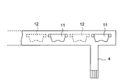
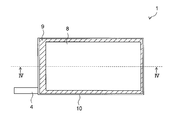
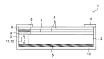
- FIG. 1 is a schematic overall plan view of an LED backlight according to the present invention. It is a schematic sectional drawing of the LED backlight which concerns on this invention. It is the schematic explaining the example with bad luminous efficiency of a conventional structure. It is the schematic explaining the example which the luminous efficiency of this invention structure improved. It is a schematic explanatory drawing which shows the 1st modification for suppressing the leakage of the light from an FPC part. It is a schematic explanatory drawing which shows the structural example which concerns on this invention for suppressing the leak of the light from a FPC part.
- the LED backlight 1 shown in FIG. 1 is an edge light type LED backlight equipped with an FPC 4 in which a visible LED light source 11 and an invisible LED light source 12 are mounted in a side view type. Moreover, it is a planar light-emitting body which makes the upper surface of the light-guide plate 2 the planar light emission surface, Comprising: In this embodiment, the upper surface 21 of the light-guide plate 2 is made into the light emission surface, and the side surface 23 is made into the incident part of light.
- the FPC 4 is disposed, for example, in parallel with the light emitting surface of the light guide plate 2, and the light source unit 3 on which the visible LED light source 11 and the invisible LED source 12 are mounted faces the side surface 23. Installed.
- the LED backlight 1 of the present embodiment is provided with the light incident part on the side surface 23 of the light guide plate 2 forming the planar light emitter, and the visible light LED light source 11 and the invisible light LED light source are provided in the incident part.
- the FPC 4 is arranged in parallel to the light emitting surface of the light guide plate 2 so that the light source unit 3 mounted in a side view type faces the side surface 23, and light is transmitted from the side surface 23 of the light guide plate to the inside of the light guide plate. This is an incident edge light type LED backlight.
- the visible LED light source 11 is, for example, a white LED light source that emits white light
- the invisible LED light source 12 is, for example, an LED light source that emits infrared light. Since infrared light is non-visible light, it can be used as light for detecting a finger or an input pen of a person who touches the display screen without affecting the image displayed on the display screen. Therefore, a backlight including a white LED light source and an infrared LED light source can be suitably applied to, for example, a touch panel display device.
- the FPC 4 has a plurality of visible LED light sources 11 and non-visible LED light sources 12 mounted alternately at a predetermined pitch. That is, the white LED light source and the infrared LED light source are mixedly mounted on the FPC 4 which is a flexible substrate having flexibility. Therefore, the LED backlight 1 according to the present embodiment can uniformly emit both visible light and invisible light over the entire surface of the light-emitting surface of the light guide plate 2.
- the FPC 4 uses a thin resin base material having flexibility, it partially transmits light. Therefore, the visible light emitted from the visible light LED light source 11 and the invisible light emitted from the invisible light LED light source 12 leak from the FPC unit, and the light incident on the light guide plate 2 is reduced. Thus, when a part of the light emitted from the LED light source leaks, the light emission intensity of the LED light source decreases.
- the reflecting member that efficiently reflects visible light does not always reflect non-visible light efficiently.
- a reflective film made of a polyester resin used for efficiently reflecting visible light (approximately 400 to 800 nm) has a low reflectance with respect to infrared light (for example, 850 to 950 nm), and this reflective film is used as a reflective member. When used, visible light is reflected efficiently, but infrared light cannot be reflected efficiently, and the luminous efficiency of infrared light is reduced.
- a reflection film 6 having a function of efficiently reflecting both visible light and invisible light is provided on the back side of the FPC 4.
- a reflection film 5 having a function of efficiently reflecting both the visible light and the invisible light is provided outside the light source unit 3 on the mounting surface side of the FPC 4.
- the LED backlight 1 according to this embodiment has the visible light and the non-light on both the first surface side corresponding to the mounting surface side of the FPC 4 and the second surface side corresponding to the back surface side of the FPC 4.
- a reflection member that reflects both visible light and guides it to the incident portion of the light guide plate 2 is provided.
- the reflection sheet is provided on the back surface of the light guide plate 2, the reflection sheet is made of a material that reflects both visible light and non-visible light, and this reflection sheet is made up to 4 parts of the FPC. It is good also as a structure extended.
- the reflection member on either the first surface side or the second surface side is configured to also serve as a reflection sheet installed on the back surface facing the light emitting surface of the light guide plate 2, the back surface of the light guide plate 2. Since both the reflective surfaces efficiently reflect both visible light and invisible light, an LED backlight capable of efficiently emitting light from the planar light emitter can be obtained.
- FIG. 3 is a schematic overall plan view of the LED backlight 1
- FIG. 4 shows a IV-IV cross section of FIG.
- the LED backlight 1 is a rectangular illumination device in plan view.
- a light guide plate 2 a diffusion sheet 7, and a lens are mounted on a chassis 10 that is a frame.
- the sheet 8 and the RIM sheet 9 are laminated in this order.
- a liquid crystal panel is mounted thereon to form a liquid crystal display device.
- the diffusion sheet 7 and the lens sheet 8 are optical members for making the light emitted from the light emitting surface of the light guide plate 2 uniform and increasing the luminance.
- the RIM sheet 9 is made of, for example, PET resin (polyethylene terephthalate). This is a frame-shaped light shielding sheet for preventing light from leaking out from the peripheral edge.
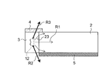
- FIG. 5A shows a state in which light leaks from the FPC 4 portion
- FIG. 5B corresponds to the outer surface of the light source portion 3 mounted on the FPC 4, that is, the front side of the FPC which is the FPC mounting surface side.
- a state in which the reflection member 5 is provided on the first surface side and the reflection member 6 is provided on the second surface side corresponding to the back surface side of the FPC to suppress leakage of light from the FPC 4 portion is shown.
- the light emitted from the invisible LED light source 12 that is an infrared LED light source corresponds to the incident light R1 that is directly incident from the side surface 23 of the light guide plate 2 and the front side of the FPC 4. It shows that there is light R2 leaking from the first surface side of the surface of the light source unit 3 and light R3 leaking from the second surface side corresponding to the back surface side of the FPC 4.
- the leaked lights R2 and R3 become lost light, and only the light emission intensity whose output is reduced can be effectively used with respect to the light emission intensity output from the invisible LED light source 12. Therefore, in order to effectively utilize the leaked lights R2 and R3, in the present embodiment, a configuration is provided in which reflecting members 5 and 6 that reflect both the visible light and the invisible light and guide them to the incident portion are provided. It was.
- the reflecting member as invisible light, for example, when infrared light having a wavelength of about 850 to 950 nm is employed, light in the visible light region having a wavelength of 400 to 800 nm and light in the infrared region having a wavelength of 850 to 950 nm are used. It is preferable to use a silver reflecting sheet that exhibits a high reflectance with respect to both. As the silver reflection sheet, a conventionally known optical silver reflection sheet can be used.
- the LED light source when the LED light source is mounted in the side view type on the FPC 4 arranged in parallel to the light emitting surface of the light guide plate 2, the first surface side corresponding to the mounting surface side of the FPC 4 and By providing the reflecting members 5 and 6 on the second surface side corresponding to the back surface side of the FPC, the light R2 leaking from the first surface side is reflected by the reflecting member 5 and enters the light guide plate 2.
- the incident light R21 that leaks from the second surface side becomes the incident light R31 that is reflected by the reflecting member 6 and enters the light guide plate 2.
- each LED light source is reflected by a reflecting member installed around the packaged LED light source and is incident on the light guide plate, predetermined light is emitted from each LED light source. Therefore, it is not necessary to have a package configuration in which the reflection characteristics are accurately defined.
- a white LED package that forms the white LED light source is used as the infrared LED light source.
- a configuration is preferable. In this way, by using a white LED package that is packaged with a light emitting unit that emits white light and equipment that emits the white light in a predetermined direction, infrared light can be used instead of the light emitter that emits white light.
- an infrared LED light source is manufactured by mounting a light emitting body that emits light
- an infrared LED package can be manufactured using a package for white LED that is mass-produced. It can be manufactured.
- the non-visible light LED package forming the non-visible light LED light source and the visible light LED package forming the visible light LED light source include a light emitting element and a fluorescent light emitting a predetermined color in a common package, respectively.
- FIG. 6A shows a first modification that is supposed to suppress light leakage from the FPC section.
- a silver reflection sheet 61 is installed as a reflection member on the mounting surface of the LED light source of the FPC 4.
- a reflecting member 6 made of a silver reflecting sheet is provided so as to cover the entire back surface side of the FPC 4.
- the reflecting member 5 made of a silver reflecting sheet is also provided on the front side facing the FPC 4, in the edge light type LED backlight, light from a light incident portion (visible light: white light and non-light) Leakage of visible light (both infrared light) can be effectively suppressed, and the LED backlight can effectively utilize the light emitted from these light sources.
- both the visible light and the invisible light are used.
- the reflecting member that reflects both of the light components on both the outer side (first surface side) of the light source unit mounted on the FPC and the rear surface side (second surface side) of the FPC, visible light can be obtained.
- Invisible light can be efficiently guided into the light guide plate, and an LED backlight capable of improving the light emission efficiency can be obtained.
- the LED backlight is a mixture of a white LED light source and an infrared LED light source
- a white LED light source and a red LED can be obtained by using a silver reflection sheet that efficiently reflects both white light and infrared light.
- An LED backlight with improved luminous efficiency can be obtained without reducing the luminous intensity of both the LED light source and the outer LED light source.
- an infrared LED light source can be produced using a package for a white LED light source, and the manufacturing cost of the LED light source Can be reduced.
- the LED backlight according to the present invention can be suitably used for an LED backlight including a plurality of LED light sources that emit light of different colors.
Landscapes
- Physics & Mathematics (AREA)
- General Physics & Mathematics (AREA)
- Optics & Photonics (AREA)
- Planar Illumination Modules (AREA)
Abstract
FPC4に可視光LED光源11と非可視光LED光源12とをサイドビュータイプに搭載して、導光板2の側面から光を入射するエッジライト型のLEDバックライトにおいて、可視光と非可視光を効率よく導光板内に導いて、発光効率を向上させることが可能なLEDバックライトを提供するために、FPC4の実装面側に相当する第一面側と、FPCの裏面側に相当する第二面側の両方に、これらの可視光と非可視光を共に反射して入射部に導光する反射部材5、6を設けた構成のLEDバックライト1とした。
Description
本発明は、液晶表示装置などに用いられるLEDバックライトに関する。
近年、発光効率の向上や発光量の増加と共に、寿命が長く消費電力が小さくて、環境にやさしいとされるLED(発光ダイオード)を用いた照明装置が実用化されつつある。また、液晶表示装置等のバックライトとして、平面状の発光面を有する導光板の側面部に複数のLED光源を設置したエッジライト型のバックライトが用いられている。
この、エッジライト型のバックライトは、それぞれが点光源となる多数のLED光源を導光板の側面部に配設した構成となる。そのために、それぞれのLED光源の輝度にばらつきが生じると、導光板に入射する光の輝度が不均一となって、発光面の発光輝度が不均一になるので、発光面の発光輝度を均一にするには、それぞれのLED光源の輝度を揃えることが肝要である。
また、LED光源の実装方式により、実装面に対して正面に向けて出射する所謂トップビュータイプのLED光源と、実装面に対して横方向に出射する所謂サイドビュータイプのLED光源が知られている。また、LED光源を実装するための基板として、リジッド基板と柔軟性を有するフレキシブル基板(フレキシブルプリント基板:FPCと称する)が用いられている。
そのために、リジッド基板にトップビュータイプにLED光源を実装したエッジライト型のバックライトにおいては、リジッド基板が導光板の側面に平行に配設され、このリジッド基板に実装されたLED光源が、光の入射部となる導光板の側面部に対向して設置される。また、FPCにサイドビュータイプにLED光源が実装されたエッジライト型のバックライトにおいては、FPCが導光板の発光面に対して平行に配設され、このFPCに実装されたLED光源が、光の入射部となる導光板の側面部に対向して設置される構成となる。
また、バックライト用の光源として、青色と緑色と赤色の三原色のLEDチップを用いて白色光を発する白色LED光源や、青色LEDチップと黄色蛍光体とで光源を構成して白色光を発する白色LED光源や、青色LEDチップと緑色蛍光体と赤色蛍光体で光源を構成して白色光を発する白色LED光源が用いられている。さらに、タッチパネル式の表示装置を構成するために、白色LED光源を用いた表示用光源と、赤外光を発光する赤外LED光源を用いた検知用光源とを混載したバックライトが用いられている。
赤外光は非可視光であるので、表示画面に表示される画像に影響を及ぼすことなく、表示画面にタッチする人の指や入力ペンを検知する光として使用ことができる。そのため、これらのタッチパネル式のバックライトには、導光板の側端部に表示用光源と検知用光源とが多数設置される構成となる。
このようなエッジライト型のバックライトでは、発光面の輝度分布を均一として高品位の表示装置を得るために、表示用光源と検知用光源とのそれぞれのLED光源の発光輝度を揃えると共に、それぞれのLED光源の発光効率を向上させることが望ましい。
エッジライト型のバックライトにおいて、LED光源の発光効率を向上させるためには、LED光源が発光する光を漏れなく導光板に入射させることが望ましいので、LED光源が設置された導光板の側端部の上面と下面にそれぞれ、上部反射板と下部反射板を設けて、LED光源から出射される光を効率よく導光板内に導き、発光面の輝度分布を均一とする点光源バックライト装置が既に提案されている(例えば、特許文献1参照)。
一般の表示装置用のバックライトとしては、可視光領域の白色LED光源を用いており、この白色LED光源から出射される白色光を効率的に反射する反射板を用いる。しかし、表示用の白色LED光源と検知用の赤外LED光源とを備えたバックライトでは、可視光のみを効率的に反射させるだけでは不十分であって、非可視光である赤外光も効率的に反射させることが好ましい。
また、特許文献1に記載されたバックライト装置は、LEDの実装面に対して正面に向けて出射する所謂トップビュータイプのLED光源であって、基板を導光板の側端面に対して平行に配置している。そのために、導光板の上面と下面に平行となるように、それぞれ反射板を設けて、この上下の反射板の間にリジッドタイプのLED光源の基板を挟持するように設置することは容易となる。
しかし、FPCを用いたサイドビュータイプのLED光源を配設したバックライトにおいては、導光板の上面もしくは下面のいずれか一方に平行となるようにFPCを配設する構成となるので、このFPC部から光が漏れ出す問題が生じる。
このように、表示用の可視光LED光源と検知用の非可視光LED光源とをFPCに装着したエッジライト型のバックライトの場合には、FPCに実装したLED光源側から漏れ出す光に加えて、FPCを透過して漏れ出す可視光や非可視光を効率よく反射して、導光板に導入することが望まれる。
そこで本発明は、上記問題点に鑑み、可視光LED光源と非可視光LED光源とをサイドビュータイプに搭載したFPCを用いたエッジライト型のバックライトにおいて、可視光と非可視光を効率よく導光板内に導いて、発光効率を向上させることが可能なLEDバックライトを提供することを目的とする。
上記目的を達成するために本発明は、上面に平面状の発光面を有し、側面に光の入射部を有する導光板と、前記側面に向けて光を出射する可視光LED光源と非可視光LED光源とがサイドビュータイプに実装された光源部を搭載したFPCと、を備え、前記FPCを前記発光面に対して平行に配設して前記光源部を前記側面に対向させるように設置し、前記側面から導光板内部に光を入射するエッジライト型のLEDバックライトにおいて、前記FPCの実装面側に相当する前記光源部の外側の第一面側と、前記FPCの裏面側に相当する第二面側の両方に、当該可視光と当該非可視光を共に反射して前記入射部に導光する反射部材を設けたことを特徴としている。
この構成によると、導光板の側部に可視光LED光源と非可視光LED光源を配設して、導光板の側部から光を入射する構成であっても、この入射部から導光板以外への光の漏れ出し、つまり、可視光と非可視光のLED光源を実装しているFPCの正面側と裏面側からの可視光と非可視光との両方の光の漏れ出しを抑制することができるので、全ての光を効率よく導光板内に導光可能となって、発光効率の向上したLEDバックライトを得ることができる。
また本発明は上記構成のLEDバックライトにおいて、前記第一面側または前記第二面側のいずれか一方の反射部材が、前記導光板の発光面と対向する背面に設置する反射シートを兼用していることを特徴としている。この構成によると、導光板の反射面も可視光と非可視光の両方の光を共に効率よく反射して、面状発光体から効率よく発光可能となるLEDバックライトを得ることができる。
また本発明は上記構成のLEDバックライトにおいて、前記可視光LED光源と前記非可視光LED光源とを交互に複数配設していることを特徴としている。この構成によると、FPCに複数種類のLED光源を混載した構成であっても、いずれの光も共に効率よく反射するので、それぞれのLED光源が発する光の有効活用が可能となって、発光効率の向上したLEDバックライトを得ることができる。
また本発明は上記構成のLEDバックライトにおいて、前記非可視光LED光源を形成する非可視光LEDパッケージと、前記可視光LED光源を形成する可視光LEDパッケージとは、共通化されたパッケージにそれぞれ所定の色を発光する発光素子および蛍光体を含む所定の発光体を搭載して構成されていることを特徴としている。この構成によると、共通化されたパッケージを用いて可視光LED光源と非可視光LED光源とを製造するので、大量生産するいずれか一方のLEDパッケージを用いて両方のLED光源を作製可能となり、生産コストを低減することができる。
また本発明は上記構成のLEDバックライトにおいて、前記可視光が白色光であり、前記非可視光が赤外光であり、前記可視光LED光源が白色LED光源であって、前記非可視光LED光源が赤外LED光源であることを特徴としている。この構成によると、白色光と赤外光との両方の光を効率よく導光可能となるLEDバックライトを得ることができる。そのために、白色LED光源と赤外LED光源の両方のLEDの発光強度が低下せず発光効率を向上することができる。
また本発明は上記構成のLEDバックライトにおいて、前記白色LED光源は、白色光を発光する発光部とこの白色光を所定方向に射出する装備品を備えてパッケージ化された白色LEDパッケージからなり、前記赤外LED光源は、前記白色LEDパッケージを利用した構成とされ、前記白色光を発光する発光体に替えて赤外光を発光する発光体を搭載して構成されていることを特徴としている。この構成によると、大量生産される白色LED用のパッケージを用いて、赤外LEDパッケージを製造可能となるので、低コストで赤外LEDパッケージを製造することができる。
また本発明は上記構成のLEDバックライトにおいて、前記反射部材が、前記白色光および前記赤外光の反射率が共に高い銀反射シートであることを特徴としている。この構成によると、可視光である白色光と、非可視光である赤外光とを両方共効率よく反射する反射部材を用いて、可視光と非可視光を効率よく導光板内に導いて、発光効率を向上させることが可能なLEDバックライトを得ることができる。
本発明によれば、サイドビュータイプに可視光LED光源と非可視光LED光源とを実装したFPCを装着したエッジライト型のLEDバックライトにおいて、FPCに対向した第一面側と、FPCの裏面に相当する第二面側の両方に、可視光と非可視光を共に反射して導光板の側部に設ける入射部に導光する反射部材を設けた構成のLEDバックライトとしたので、可視光と非可視光を効率よく導光板内に導くことができ、それぞれのLEDの発光効率を向上させることが可能なLEDバックライトを得ることができる。
以下に本発明の実施形態を図面を参照して説明する。また、同一構成部材については同一の符号を用い、詳細な説明は適宜省略する。
まず、図1を用いて本実施形態のLEDバックライトの一例について説明する。
図1に示すLEDバックライト1は、サイドビュータイプに可視光LED光源11と非可視光LED光源12とを実装したFPC4を装着したエッジライト型のLEDバックライトである。また、導光板2の上面を平面状の発光面とする面状発光体であって、本実施形態では、導光板2の上面21を発光面とし、側面23を光の入射部としている。
また、FPC4は、例えば、導光板2の発光面に対して平行に配設されていて、可視光LED光源11と非可視光LED光源12とが実装された光源部3が側面23に対向して設置されている。このように、本実施形態のLEDバックライト1は、面状発光体を形成する導光板2の側面23に光の入射部を設け、該入射部に可視光LED光源11と非可視光LED光源12とがサイドビュータイプに実装された光源部3を側面23に対向させるようにFPC4を導光板2の発光面に対して平行に配設し、導光板の側面23から導光板内部に光を入射するエッジライト型のLEDバックライトである。
可視光LED光源11は、例えば、白色光を発光する白色LED光源であり、非可視光LED光源12は、例えば、赤外光を発光するLED光源である。赤外光は非可視光であるので、表示画面に表示される画像に影響を及ぼすことなく、表示画面にタッチする人の指や入力ペンを検知する光として利用することができる。そのために、白色LED光源と赤外LED光源とを備えるバックライトは、例えば、タッチパネル式の表示装置に好適に適用可能となる。
図2に示すように、本実施形態に係るFPC4は、可視光LED光源11と非可視光LED光源12とを交互に所定のピッチで複数実装している。つまり、柔軟性を有するフレキシブル基板であるFPC4に白色LED光源と赤外LED光源を混載している。そのために、本実施形態に係るLEDバックライト1は、可視光と非可視光との両方の光を、導光板2の面状発光面に全面に亘って均一に発光させることができる。
FPC4は、柔軟性を有する樹脂製の薄い基材を用いているので、光を一部透過させてしまう。そのために、可視光LED光源11が発する可視光と非可視光LED光源12が発する非可視光がこのFPC部から漏れ出してしまい、導光板2に入射する光が減少する。このように、LED光源から出射した光の一部が漏れ出すと、当該LED光源の発光強度が低下することになる。
また、可視光と非可視光とでは、光の波長が異なるので、可視光を効率よく反射する反射部材が、非可視光をも効率よく反射するとは限らない。特に、可視光(おおよそ、400~800nm)を効率よく反射させるために用いるポリエステル系樹脂からなる反射フィルムは赤外光(例えば、850~950nm)に対する反射率が低く、この反射フィルムを反射部材として用いると、可視光は効率よく反射するが、赤外光は効率よく反射することができなくなってしまい、赤外光の発光効率が低下することになる。
そのために、本実施形態では図1に示すように、FPC4の裏面側に当該可視光と非可視光を共に効率よく反射する機能を有する反射膜6を設けた構成としている。また、FPC4の実装面側となる光源部3の外側にも当該可視光と非可視光を共に効率よく反射する機能を有する反射膜5を設けている。このように、本実施形態に係るLEDバックライト1は、FPC4の実装面側に相当する第一面側と、FPC4の裏面側に相当する第二面側の両方に、当該可視光と当該非可視光を共に反射して導光板2の入射部に導光する反射部材を設けた構成としている。
上記の構成であれば、導光板2の側部に可視光LED光源と非可視光LED光源を配設して、導光板2の側部から光を入射する構成であっても、この入射部から導光板以外への光の漏れ出し、つまり、可視光と非可視光のLED光源を実装しているFPC4の正面側と裏面側からの可視光と非可視光との両方の光の漏れ出しを抑制することができるので、全ての光を効率よく導光板内に導光可能となって、発光強度が低下せず発光効率の向上したLEDバックライト1を得ることができる。
また、導光板2の背面に反射シートを設けた構成であれば、この反射シートを可視光と非可視光との両方の光を反射する素材から作製し、この反射シ-トをFPC4部まで延設する構成としてもよい。このように、第一面側または第二面側のいずれか一方の反射部材が、導光板2の発光面と対向する背面に設置する反射シートを兼用する構成であれば、導光板2の背面の反射面も可視光と非可視光の両方の光を共に効率よく反射するので、面状発光体から効率よく発光可能となるLEDバックライトを得ることができる。
次に、図3および図4を用いてLEDバックライト1の全体構成について説明する。図3は、LEDバックライト1の概略全体平面図であり、図4は、図3のIV-IV断面を示している。
図3に示すように、本実施形態に係るLEDバックライト1は平面視四角形の照明装置であって、図4に示すように、枠体であるシャーシ10に導光板2、拡散シート7、レンズシート8、RIMシート9をこの順に積層して構成されている。また、この上に例えば液晶パネルを搭載して液晶表示装置が形成される。
拡散シート7およびレンズシート8は、導光板2の発光面から出射される光を均一にすると共に輝度を高めるための光学部材であり、RIMシート9は、例えば、PET樹脂(ポリエチレン・テレフタレート)からなる額縁状の遮光シートであって、光が周縁部から漏れ出さないようにするためのものである。
次に、図5A、図5Bを用いて光の入射部からの光の漏れ出しについて説明する。
図5AにはFPC4部から光が漏れ出している状態を示し、図5Bには、このFPC4に搭載される光源部3の外側の面、つまりFPCの実装面側であるFPCの正面側に相当する第一面側に反射部材5を設け、FPCの裏面側に相当する第二面側に反射部材6を設けて、このFPC4部からの光の漏れ出しを抑制している状態を示す。
図5Aに示す状態では、例えば、赤外LED光源である非可視光LED光源12から出射される光として、導光板2の側面23から直接入射する入射光R1と、FPC4の正面側に相当する光源部3の表面の第一面側から漏れ出している光R2と、FPC4の裏面側に相当する第二面側から漏れ出している光R3とがあることを示している。
この状態では、漏れ出す光R2とR3とが損失光となって、非可視光LED光源12が出力する発光強度に対して、出力が低下した発光強度しか有効に利用できない構成となる。そのために、この漏れ出す光R2とR3を有効に活用するために、本実施形態では、当該可視光と非可視光を共に反射して前記入射部に導光する反射部材5、6を設ける構成とした。
この反射部材としては、非可視光として、例えば波長850~950nm程度の赤外光を採用する場合には、波長400~800nmの可視光領域の光と、波長850~950nmの赤外領域の光との両方に対して高い反射率を発揮する銀反射シートを用いることが好ましい。銀反射シートは従来公知の光学銀反射シートを用いることができる。
図5Bに示すように、導光板2の発光面に対して平行に配設されるFPC4に、LED光源をサイドビュータイプに実装する際に、FPC4の実装面側に相当する第一面側とFPCの裏面側に相当する第二面側に、それぞれ反射部材5、6を設ける構成とすることで、第一面側から漏れ出す光R2が、反射部材5により反射されて導光板2に入射する入射光R21となり、第二面側から漏れ出す光R3が、反射部材6により反射されて導光板2に入射する入射光R31となる。
非可視光LED光源12と共に混載されている可視光LED光源11から発光される可視光も反射部材5、6により全て導光板2に入射することは明らかであるので、本実施形態に係るLEDバックライト1を用いることで、可視光LED光源と非可視光LED光源とが発光する光を有効に活用することが可能となり、可視光と非可視光との両方の発光強度が低下せず発光効率を向上することができる。
また、それぞれのLED光源から発光される光を、このパッケージ化されたLED光源の周囲に設置する反射部材により反射して、導光板に入射させる構成となるので、それぞれのLED光源において所定の光の反射特性を正確に規定したパッケージ構成とする必要がなくなる。
つまり、発光素子を実装する基板やリフレクタなどの装備品を共通化して使用しても、所定の発光特性を発揮することができる。そのために、一方のLED光源に用いるパッケージを利用して、それぞれの所定の色を発光する発光体を入れ替えて搭載することで、所定の発光色のLED光源を作製することが可能となる。例えば、大量生産することで安価に製造される一方のLED光源に用いるパッケージに、この当該LED光源の発光体を、他方のLED光源用の発光体に入れ替えることで、この他方のLED光源も安価に作製可能となる。
そのために、大量生産される白色LED光源と赤外LED光源とを混載して構成されるLEDバックライトの場合には、赤外LED光源を、白色LED光源を形成する白色LED用パッケージを利用した構成とすることが好ましい。このように、白色光を発光する発光部とこの白色光を所定方向に射出する装備品を備えてパッケージ化された白色LEDパッケージを利用して、白色光を発光する発光体に替えて赤外光を発光する発光体を搭載して赤外LED光源を作製すると、大量生産される白色LED用のパッケージを用いて、赤外LEDパッケージを製造可能となるので、低コストで赤外LEDパッケージを製造することが可能となる。
このように、非可視光LED光源を形成する非可視光LEDパッケージと、可視光LED光源を形成する可視光LEDパッケージとは、共通化されたパッケージにそれぞれ所定の色を発光する発光素子および蛍光体を含む所定の発光体を搭載して構成されることが、低コスト化のためには好ましい。
以上、説明したように、エッジライト型のLEDバックライトの光の入射部に可視光LED光源と非可視光LED光源を共に配設した構成であっても、これらのLED光源を実装しているFPCの正面側と裏面側からのこれらの可視光と非可視光との両方の光の漏れ出しを抑制する反射部材を用いることで、全ての光を効率よく導光板内に導光可能となり、発光効率の向上したLEDバックライトを得ることができる。
次に、図6A、図6Bを用いて、FPCからの光の漏れ出しを抑制する方法について説明する。
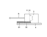
図6AにはFPC部からの光の漏れ出しを抑制するために想定される第一の変形例を示している。この例は、FPC4のLED光源の実装面に反射部材として銀反射シート61を設置するものである。
この構成でも、FPC4からの光の漏れ出しを抑制して出射光R方向に反射可能に思えるが、下記のような不具合があって好ましくない。まず、第一に、実装面に配設している銀反射シート61がLED電極部30やランド部などに接触して電気的にショートする虞がある。第二に、LED光源の裏面部からの光の漏れ出しを抑制することができない。また、第三に、LED出射面に干渉して出射光Rを遮光してしまう虞が生じる。
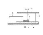
そのために、本実施形態では、図6Bに示すように、FPC4の裏面側の全体を覆うように銀反射シートからなる反射部材6を配設したものである。
この構成であれば、この銀反射シートがLED電極部30やランド部などに接触して電気的にショートする虞も生じず、LED光源の裏面部からの光の漏れ出しも抑制可能となり、LED出射面に干渉して出射光Rを遮光する虞も生じない。
また、FPC4に対向する正面側にも、銀反射シートからなる反射部材5を配設しているので、エッジライト型のLEDバックライトにおいて、光入射部からの光(可視光:白色光と非可視光:赤外光の両方の光)の漏れ出しを効果的に抑制可能となり、これらの光源から発光される光を有効に活用できるLEDバックライトとなる。
そのために、可視光を効率よく反射させるポリエステル系樹脂からなる反射フィルムを用いたものでは困難となる、赤外光などの非可視光も含めた光の有効活用を実現することができる。
上記したように、本発明によれば、可視光LED光源と非可視光LED光源とをサイドビュータイプに搭載したFPCを用いたエッジライト型のバックライトにおいて、この可視光と非可視光の両方の光を共に反射する反射部材をFPCに搭載された光源部の外側(第一面側)とFPCの裏面側(第二面側)との両面に配設する構成とすることで、可視光と非可視光を効率よく導光板内に導いて、発光効率を向上させることが可能なLEDバックライトを得ることができる。
また、白色LED光源と赤外LED光源とを混載したLEDバックライトであれば、白色光と赤外光との両方の光を効率よく反射する銀反射シートを用いることで、白色LED光源と赤外LED光源との両方のLED光源の発光強度を低下せず発光効率を向上したLEDバックライトを得ることができる。
さらに、白色光と赤外光との両方の光を効率よく反射する銀反射シートを用いることで、白色LED光源用のパッケージを利用して赤外LED光源を作製可能となり、LED光源の製造コストを低減可能となる。
そのために本発明に係るLEDバックライトは、異なる色で発光する複数のLED光源を備えるLEDバックライトに好適に利用可能となる。
1 LEDバックライト
2 導光板
3 光源部
4 FPC(フレキシブルプリント基板)
5 反射部材
6 反射部材
11 可視光LED光源(白色LED光源)
12 非可視光LED光源(赤外LED光源)
R1 入射光
R2 光(漏れ出す光)
R21 入射光
R3 光(漏れ出す光)
R31 入射光
2 導光板
3 光源部
4 FPC(フレキシブルプリント基板)
5 反射部材
6 反射部材
11 可視光LED光源(白色LED光源)
12 非可視光LED光源(赤外LED光源)
R1 入射光
R2 光(漏れ出す光)
R21 入射光
R3 光(漏れ出す光)
R31 入射光
Claims (7)
- 上面に平面状の発光面を有し、側面に光の入射部を有する導光板と、
前記側面に向けて光を出射する可視光LED光源と非可視光LED光源とがサイドビュータイプに実装された光源部を搭載したFPCと、を備え、
前記FPCを前記発光面に対して平行に配設して前記光源部を前記側面に対向させるように設置し、前記側面から導光板内部に光を入射するエッジライト型のLEDバックライトにおいて、
前記FPCの実装面側に相当する前記光源部の外側の第一面側と、前記FPCの裏面側に相当する第二面側の両方に、当該可視光と当該非可視光を共に反射して前記入射部に導光する反射部材を設けたことを特徴とするLEDバックライト。 - 前記第一面側または前記第二面側のいずれか一方の反射部材が、前記導光板の発光面と対向する背面に設置する反射シートを兼用していることを特徴とする請求項1に記載のLEDバックライト。
- 前記可視光LED光源と前記非可視光LED光源とを交互に複数配設していることを特徴とする請求項1または2に記載のLEDバックライト。
- 前記非可視光LED光源を形成する非可視光LEDパッケージと、前記可視光LED光源を形成する可視光LEDパッケージとは、共通化されたパッケージにそれぞれ所定の色で発光する発光素子および蛍光体を含む所定の発光体を搭載して構成されていることを特徴とする請求項1から3のいずれかに記載のLEDバックライト。
- 前記可視光が白色光であり、前記非可視光が赤外光であり、前記可視光LED光源が白色LED光源であって、前記非可視光LED光源が赤外LED光源であることを特徴とする請求項1から4のいずれかに記載のLEDバックライト。
- 前記白色LED光源は、白色光を発光する発光部とこの白色光を所定方向に射出する装備品を備えてパッケージ化された白色LEDパッケージからなり、前記赤外LED光源は、前記白色LEDパッケージを利用した構成とされ、前記白色光を発光する発光体に替えて赤外光を発光する発光体を搭載して構成されていることを特徴とする請求項5に記載のLEDバックライト。
- 前記反射部材が、前記白色光および前記赤外光の反射率が共に高い銀反射シートであることを特徴とする請求項5または6に記載のLEDバックライト。
Priority Applications (1)
| Application Number | Priority Date | Filing Date | Title |
|---|---|---|---|
| US13/637,114 US20130010496A1 (en) | 2010-04-07 | 2011-01-24 | Led backlight |
Applications Claiming Priority (2)
| Application Number | Priority Date | Filing Date | Title |
|---|---|---|---|
| JP2010088604 | 2010-04-07 | ||
| JP2010-088604 | 2010-04-07 |
Publications (1)
| Publication Number | Publication Date |
|---|---|
| WO2011125359A1 true WO2011125359A1 (ja) | 2011-10-13 |
Family
ID=44762326
Family Applications (1)
| Application Number | Title | Priority Date | Filing Date |
|---|---|---|---|
| PCT/JP2011/051201 Ceased WO2011125359A1 (ja) | 2010-04-07 | 2011-01-24 | Ledバックライト |
Country Status (2)
| Country | Link |
|---|---|
| US (1) | US20130010496A1 (ja) |
| WO (1) | WO2011125359A1 (ja) |
Cited By (2)
| Publication number | Priority date | Publication date | Assignee | Title |
|---|---|---|---|---|
| WO2013115303A1 (ja) * | 2012-02-02 | 2013-08-08 | シャープ株式会社 | 光源保持部材及び照明装置 |
| CN109753190A (zh) * | 2018-12-28 | 2019-05-14 | 惠科股份有限公司 | 一种触控装置、显示装置和触摸检测方法 |
Families Citing this family (7)
| Publication number | Priority date | Publication date | Assignee | Title |
|---|---|---|---|---|
| US9041692B2 (en) * | 2010-07-26 | 2015-05-26 | Sharp Kabushiki Kaisha | Display device |
| WO2012090790A1 (ja) * | 2010-12-27 | 2012-07-05 | シャープ株式会社 | タッチパネル |
| KR20150001025A (ko) | 2013-06-26 | 2015-01-06 | 삼성디스플레이 주식회사 | 광원 어셈블리, 이를 포함하는 표시 장치 및 이의 제조 방법 |
| KR102090156B1 (ko) | 2013-07-04 | 2020-03-18 | 삼성디스플레이 주식회사 | 표시장치 |
| CN103939799B (zh) * | 2014-03-31 | 2015-11-25 | 京东方科技集团股份有限公司 | 一种背光模组及液晶显示装置 |
| CN113508260B (zh) * | 2019-01-09 | 2023-11-10 | 亮锐控股有限公司 | 用于显示屏的背光照明的照明设备 |
| CN112749601B (zh) * | 2019-10-31 | 2025-07-29 | 北京小米移动软件有限公司 | 屏下指纹识别系统、背光模组、光源组件及显示屏幕 |
Citations (4)
| Publication number | Priority date | Publication date | Assignee | Title |
|---|---|---|---|---|
| JP2000286454A (ja) * | 2000-01-01 | 2000-10-13 | Sanken Electric Co Ltd | 半導体面状光源 |
| JP2006331659A (ja) * | 2005-05-23 | 2006-12-07 | Mitsubishi Electric Corp | 面状光源装置及びこれを用いた表示装置 |
| JP2008117886A (ja) * | 2006-11-02 | 2008-05-22 | Harison Toshiba Lighting Corp | Ledパッケージ及び照明装置 |
| JP2009129317A (ja) * | 2007-11-27 | 2009-06-11 | Sony Corp | 表示装置及び光学装置 |
Family Cites Families (4)
| Publication number | Priority date | Publication date | Assignee | Title |
|---|---|---|---|---|
| JP4584116B2 (ja) * | 2005-11-04 | 2010-11-17 | Nec液晶テクノロジー株式会社 | 点光源バックライト |
| CN101688657B (zh) * | 2007-06-28 | 2012-06-20 | 夏普株式会社 | 背光装置、液晶显示装置以及照明装置 |
| JP2009032005A (ja) * | 2007-07-26 | 2009-02-12 | Toshiba Corp | 入力表示装置および入力表示パネル |
| US8384097B2 (en) * | 2009-04-08 | 2013-02-26 | Ledengin, Inc. | Package for multiple light emitting diodes |
-
2011
- 2011-01-24 US US13/637,114 patent/US20130010496A1/en not_active Abandoned
- 2011-01-24 WO PCT/JP2011/051201 patent/WO2011125359A1/ja not_active Ceased
Patent Citations (4)
| Publication number | Priority date | Publication date | Assignee | Title |
|---|---|---|---|---|
| JP2000286454A (ja) * | 2000-01-01 | 2000-10-13 | Sanken Electric Co Ltd | 半導体面状光源 |
| JP2006331659A (ja) * | 2005-05-23 | 2006-12-07 | Mitsubishi Electric Corp | 面状光源装置及びこれを用いた表示装置 |
| JP2008117886A (ja) * | 2006-11-02 | 2008-05-22 | Harison Toshiba Lighting Corp | Ledパッケージ及び照明装置 |
| JP2009129317A (ja) * | 2007-11-27 | 2009-06-11 | Sony Corp | 表示装置及び光学装置 |
Cited By (3)
| Publication number | Priority date | Publication date | Assignee | Title |
|---|---|---|---|---|
| WO2013115303A1 (ja) * | 2012-02-02 | 2013-08-08 | シャープ株式会社 | 光源保持部材及び照明装置 |
| CN109753190A (zh) * | 2018-12-28 | 2019-05-14 | 惠科股份有限公司 | 一种触控装置、显示装置和触摸检测方法 |
| CN109753190B (zh) * | 2018-12-28 | 2022-01-07 | 惠科股份有限公司 | 一种触控装置、显示装置和触摸检测方法 |
Also Published As
| Publication number | Publication date |
|---|---|
| US20130010496A1 (en) | 2013-01-10 |
Similar Documents
| Publication | Publication Date | Title |
|---|---|---|
| WO2011125359A1 (ja) | Ledバックライト | |
| US8384848B2 (en) | Edge-lighting LED backlight and LCD thereof | |
| US8622600B2 (en) | Backlight module and display device using the same | |
| US9523960B2 (en) | Illumination device, display apparatus, and timepiece | |
| TWI536081B (zh) | 背光單元及使用該背光單元的顯示裝置 | |
| KR102622376B1 (ko) | 백라이트 유닛 및 그를 포함하는 표시장치 | |
| JP4813383B2 (ja) | 導光シート | |
| KR20110068110A (ko) | 양자점을 이용한 백라이트 유닛 및 이를 포함하는 액정표시장치 | |
| JP2004311353A (ja) | 面状光源装置および該装置を用いた液晶表示装置 | |
| CN112817176B (zh) | 背光单元和包括该背光单元的显示装置 | |
| JP7638341B2 (ja) | 発光装置、表示装置および照明装置 | |
| JP2019021488A (ja) | 照明装置および液晶表示装置 | |
| US20040100788A1 (en) | Light module for LCD panel | |
| US11231616B2 (en) | Color conversion sheet, backlight unit and display device | |
| US11789311B2 (en) | Illumination device including a first and a second light reduction portion and a display device including the same | |
| US6871973B2 (en) | Light module for LCD panel | |
| KR102711182B1 (ko) | 백라이트 유닛 및 그를 포함하는 표시장치 | |
| KR102633934B1 (ko) | 백라이트 유닛 및 그를 포함하는 표시장치 | |
| KR20120031581A (ko) | 도광판 및 그를 이용한 백라이트 유닛 | |
| WO2012066887A1 (ja) | 照明装置およびこれを備えた液晶表示装置 | |
| WO2013038655A1 (ja) | 照明装置及びそれを備えた表示装置 | |
| JP2017069154A (ja) | 照明装置、表示装置及びテレビ受信装置 | |
| JP2012094283A (ja) | 面状照明装置 | |
| JPWO2014046140A1 (ja) | エッジライト型面光源装置 | |
| TWI869845B (zh) | 觸控板及其背光模組 |
Legal Events
| Date | Code | Title | Description |
|---|---|---|---|
| 121 | Ep: the epo has been informed by wipo that ep was designated in this application |
Ref document number: 11765261 Country of ref document: EP Kind code of ref document: A1 |
|
| WWE | Wipo information: entry into national phase |
Ref document number: 13637114 Country of ref document: US |
|
| NENP | Non-entry into the national phase |
Ref country code: DE |
|
| 122 | Ep: pct application non-entry in european phase |
Ref document number: 11765261 Country of ref document: EP Kind code of ref document: A1 |
|
| NENP | Non-entry into the national phase |
Ref country code: JP |