WO2011122566A1 - Light intensity monitoring circuit and fiber laser system - Google Patents
Light intensity monitoring circuit and fiber laser system Download PDFInfo
- Publication number
- WO2011122566A1 WO2011122566A1 PCT/JP2011/057652 JP2011057652W WO2011122566A1 WO 2011122566 A1 WO2011122566 A1 WO 2011122566A1 JP 2011057652 W JP2011057652 W JP 2011057652W WO 2011122566 A1 WO2011122566 A1 WO 2011122566A1
- Authority
- WO
- WIPO (PCT)
- Prior art keywords
- fiber
- light
- cladding
- delivery fiber
- backward
- Prior art date
Links
- 239000000835 fiber Substances 0.000 title claims abstract description 194
- 238000012544 monitoring process Methods 0.000 title claims description 10
- 238000001514 detection method Methods 0.000 claims abstract description 39
- 230000001902 propagating effect Effects 0.000 claims abstract description 25
- 238000005253 cladding Methods 0.000 claims description 65
- 230000002441 reversible effect Effects 0.000 claims description 20
- 230000008878 coupling Effects 0.000 claims description 12
- 238000010168 coupling process Methods 0.000 claims description 12
- 238000005859 coupling reaction Methods 0.000 claims description 12
- 230000003287 optical effect Effects 0.000 claims description 9
- 230000001681 protective effect Effects 0.000 claims description 8
- 239000012530 fluid Substances 0.000 claims description 5
- 230000002123 temporal effect Effects 0.000 claims description 3
- 230000000644 propagated effect Effects 0.000 abstract 1
- 238000002310 reflectometry Methods 0.000 description 22
- 239000013307 optical fiber Substances 0.000 description 18
- 239000000463 material Substances 0.000 description 9
- 238000000034 method Methods 0.000 description 6
- 238000012545 processing Methods 0.000 description 5
- 230000008859 change Effects 0.000 description 4
- 230000004927 fusion Effects 0.000 description 4
- 238000002955 isolation Methods 0.000 description 4
- XLYOFNOQVPJJNP-UHFFFAOYSA-N water Substances O XLYOFNOQVPJJNP-UHFFFAOYSA-N 0.000 description 4
- 238000004891 communication Methods 0.000 description 3
- 238000010586 diagram Methods 0.000 description 3
- 230000008901 benefit Effects 0.000 description 2
- 239000011521 glass Substances 0.000 description 2
- 239000002184 metal Substances 0.000 description 2
- 230000008569 process Effects 0.000 description 2
- 230000005855 radiation Effects 0.000 description 2
- 230000020169 heat generation Effects 0.000 description 1
- 238000012986 modification Methods 0.000 description 1
- 230000004048 modification Effects 0.000 description 1
- 238000012806 monitoring device Methods 0.000 description 1
- 230000003014 reinforcing effect Effects 0.000 description 1
- 230000035945 sensitivity Effects 0.000 description 1
Images


Classifications
-
- G—PHYSICS
- G01—MEASURING; TESTING
- G01J—MEASUREMENT OF INTENSITY, VELOCITY, SPECTRAL CONTENT, POLARISATION, PHASE OR PULSE CHARACTERISTICS OF INFRARED, VISIBLE OR ULTRAVIOLET LIGHT; COLORIMETRY; RADIATION PYROMETRY
- G01J1/00—Photometry, e.g. photographic exposure meter
- G01J1/42—Photometry, e.g. photographic exposure meter using electric radiation detectors
- G01J1/4257—Photometry, e.g. photographic exposure meter using electric radiation detectors applied to monitoring the characteristics of a beam, e.g. laser beam, headlamp beam
-
- B—PERFORMING OPERATIONS; TRANSPORTING
- B23—MACHINE TOOLS; METAL-WORKING NOT OTHERWISE PROVIDED FOR
- B23K—SOLDERING OR UNSOLDERING; WELDING; CLADDING OR PLATING BY SOLDERING OR WELDING; CUTTING BY APPLYING HEAT LOCALLY, e.g. FLAME CUTTING; WORKING BY LASER BEAM
- B23K26/00—Working by laser beam, e.g. welding, cutting or boring
- B23K26/02—Positioning or observing the workpiece, e.g. with respect to the point of impact; Aligning, aiming or focusing the laser beam
- B23K26/04—Automatically aligning, aiming or focusing the laser beam, e.g. using the back-scattered light
-
- G—PHYSICS
- G01—MEASURING; TESTING
- G01M—TESTING STATIC OR DYNAMIC BALANCE OF MACHINES OR STRUCTURES; TESTING OF STRUCTURES OR APPARATUS, NOT OTHERWISE PROVIDED FOR
- G01M11/00—Testing of optical apparatus; Testing structures by optical methods not otherwise provided for
- G01M11/30—Testing of optical devices, constituted by fibre optics or optical waveguides
- G01M11/31—Testing of optical devices, constituted by fibre optics or optical waveguides with a light emitter and a light receiver being disposed at the same side of a fibre or waveguide end-face, e.g. reflectometers
-
- G—PHYSICS
- G02—OPTICS
- G02B—OPTICAL ELEMENTS, SYSTEMS OR APPARATUS
- G02B6/00—Light guides; Structural details of arrangements comprising light guides and other optical elements, e.g. couplings
- G02B6/02—Optical fibres with cladding with or without a coating
- G02B6/02057—Optical fibres with cladding with or without a coating comprising gratings
- G02B6/02076—Refractive index modulation gratings, e.g. Bragg gratings
- G02B6/0208—Refractive index modulation gratings, e.g. Bragg gratings characterised by their structure, wavelength response
- G02B6/02085—Refractive index modulation gratings, e.g. Bragg gratings characterised by their structure, wavelength response characterised by the grating profile, e.g. chirped, apodised, tilted, helical
-
- G—PHYSICS
- G02—OPTICS
- G02B—OPTICAL ELEMENTS, SYSTEMS OR APPARATUS
- G02B6/00—Light guides; Structural details of arrangements comprising light guides and other optical elements, e.g. couplings
- G02B6/24—Coupling light guides
- G02B6/26—Optical coupling means
- G02B6/262—Optical details of coupling light into, or out of, or between fibre ends, e.g. special fibre end shapes or associated optical elements
-
- G—PHYSICS
- G02—OPTICS
- G02B—OPTICAL ELEMENTS, SYSTEMS OR APPARATUS
- G02B6/00—Light guides; Structural details of arrangements comprising light guides and other optical elements, e.g. couplings
- G02B6/24—Coupling light guides
- G02B6/26—Optical coupling means
- G02B6/28—Optical coupling means having data bus means, i.e. plural waveguides interconnected and providing an inherently bidirectional system by mixing and splitting signals
- G02B6/2804—Optical coupling means having data bus means, i.e. plural waveguides interconnected and providing an inherently bidirectional system by mixing and splitting signals forming multipart couplers without wavelength selective elements, e.g. "T" couplers, star couplers
- G02B6/2821—Optical coupling means having data bus means, i.e. plural waveguides interconnected and providing an inherently bidirectional system by mixing and splitting signals forming multipart couplers without wavelength selective elements, e.g. "T" couplers, star couplers using lateral coupling between contiguous fibres to split or combine optical signals
- G02B6/2826—Optical coupling means having data bus means, i.e. plural waveguides interconnected and providing an inherently bidirectional system by mixing and splitting signals forming multipart couplers without wavelength selective elements, e.g. "T" couplers, star couplers using lateral coupling between contiguous fibres to split or combine optical signals using mechanical machining means for shaping of the couplers, e.g. grinding or polishing
-
- G—PHYSICS
- G01—MEASURING; TESTING
- G01J—MEASUREMENT OF INTENSITY, VELOCITY, SPECTRAL CONTENT, POLARISATION, PHASE OR PULSE CHARACTERISTICS OF INFRARED, VISIBLE OR ULTRAVIOLET LIGHT; COLORIMETRY; RADIATION PYROMETRY
- G01J1/00—Photometry, e.g. photographic exposure meter
- G01J1/02—Details
- G01J1/04—Optical or mechanical part supplementary adjustable parts
- G01J1/0407—Optical elements not provided otherwise, e.g. manifolds, windows, holograms, gratings
- G01J1/0425—Optical elements not provided otherwise, e.g. manifolds, windows, holograms, gratings using optical fibers
-
- H—ELECTRICITY
- H01—ELECTRIC ELEMENTS
- H01S—DEVICES USING THE PROCESS OF LIGHT AMPLIFICATION BY STIMULATED EMISSION OF RADIATION [LASER] TO AMPLIFY OR GENERATE LIGHT; DEVICES USING STIMULATED EMISSION OF ELECTROMAGNETIC RADIATION IN WAVE RANGES OTHER THAN OPTICAL
- H01S3/00—Lasers, i.e. devices using stimulated emission of electromagnetic radiation in the infrared, visible or ultraviolet wave range
- H01S3/0014—Monitoring arrangements not otherwise provided for
-
- H—ELECTRICITY
- H01—ELECTRIC ELEMENTS
- H01S—DEVICES USING THE PROCESS OF LIGHT AMPLIFICATION BY STIMULATED EMISSION OF RADIATION [LASER] TO AMPLIFY OR GENERATE LIGHT; DEVICES USING STIMULATED EMISSION OF ELECTROMAGNETIC RADIATION IN WAVE RANGES OTHER THAN OPTICAL
- H01S3/00—Lasers, i.e. devices using stimulated emission of electromagnetic radiation in the infrared, visible or ultraviolet wave range
- H01S3/005—Optical devices external to the laser cavity, specially adapted for lasers, e.g. for homogenisation of the beam or for manipulating laser pulses, e.g. pulse shaping
- H01S3/0064—Anti-reflection devices, e.g. optical isolaters
-
- H—ELECTRICITY
- H01—ELECTRIC ELEMENTS
- H01S—DEVICES USING THE PROCESS OF LIGHT AMPLIFICATION BY STIMULATED EMISSION OF RADIATION [LASER] TO AMPLIFY OR GENERATE LIGHT; DEVICES USING STIMULATED EMISSION OF ELECTROMAGNETIC RADIATION IN WAVE RANGES OTHER THAN OPTICAL
- H01S3/00—Lasers, i.e. devices using stimulated emission of electromagnetic radiation in the infrared, visible or ultraviolet wave range
- H01S3/05—Construction or shape of optical resonators; Accommodation of active medium therein; Shape of active medium
- H01S3/06—Construction or shape of active medium
- H01S3/063—Waveguide lasers, i.e. whereby the dimensions of the waveguide are of the order of the light wavelength
- H01S3/067—Fibre lasers
- H01S3/0675—Resonators including a grating structure, e.g. distributed Bragg reflectors [DBR] or distributed feedback [DFB] fibre lasers
-
- H—ELECTRICITY
- H01—ELECTRIC ELEMENTS
- H01S—DEVICES USING THE PROCESS OF LIGHT AMPLIFICATION BY STIMULATED EMISSION OF RADIATION [LASER] TO AMPLIFY OR GENERATE LIGHT; DEVICES USING STIMULATED EMISSION OF ELECTROMAGNETIC RADIATION IN WAVE RANGES OTHER THAN OPTICAL
- H01S3/00—Lasers, i.e. devices using stimulated emission of electromagnetic radiation in the infrared, visible or ultraviolet wave range
- H01S3/09—Processes or apparatus for excitation, e.g. pumping
- H01S3/091—Processes or apparatus for excitation, e.g. pumping using optical pumping
- H01S3/094—Processes or apparatus for excitation, e.g. pumping using optical pumping by coherent light
- H01S3/094003—Processes or apparatus for excitation, e.g. pumping using optical pumping by coherent light the pumped medium being a fibre
- H01S3/094011—Processes or apparatus for excitation, e.g. pumping using optical pumping by coherent light the pumped medium being a fibre with bidirectional pumping, i.e. with injection of the pump light from both two ends of the fibre
-
- H—ELECTRICITY
- H01—ELECTRIC ELEMENTS
- H01S—DEVICES USING THE PROCESS OF LIGHT AMPLIFICATION BY STIMULATED EMISSION OF RADIATION [LASER] TO AMPLIFY OR GENERATE LIGHT; DEVICES USING STIMULATED EMISSION OF ELECTROMAGNETIC RADIATION IN WAVE RANGES OTHER THAN OPTICAL
- H01S3/00—Lasers, i.e. devices using stimulated emission of electromagnetic radiation in the infrared, visible or ultraviolet wave range
- H01S3/09—Processes or apparatus for excitation, e.g. pumping
- H01S3/091—Processes or apparatus for excitation, e.g. pumping using optical pumping
- H01S3/094—Processes or apparatus for excitation, e.g. pumping using optical pumping by coherent light
- H01S3/09408—Pump redundancy
-
- H—ELECTRICITY
- H01—ELECTRIC ELEMENTS
- H01S—DEVICES USING THE PROCESS OF LIGHT AMPLIFICATION BY STIMULATED EMISSION OF RADIATION [LASER] TO AMPLIFY OR GENERATE LIGHT; DEVICES USING STIMULATED EMISSION OF ELECTROMAGNETIC RADIATION IN WAVE RANGES OTHER THAN OPTICAL
- H01S3/00—Lasers, i.e. devices using stimulated emission of electromagnetic radiation in the infrared, visible or ultraviolet wave range
- H01S3/09—Processes or apparatus for excitation, e.g. pumping
- H01S3/091—Processes or apparatus for excitation, e.g. pumping using optical pumping
- H01S3/094—Processes or apparatus for excitation, e.g. pumping using optical pumping by coherent light
- H01S3/0941—Processes or apparatus for excitation, e.g. pumping using optical pumping by coherent light of a laser diode
- H01S3/09415—Processes or apparatus for excitation, e.g. pumping using optical pumping by coherent light of a laser diode the pumping beam being parallel to the lasing mode of the pumped medium, e.g. end-pumping
-
- H—ELECTRICITY
- H01—ELECTRIC ELEMENTS
- H01S—DEVICES USING THE PROCESS OF LIGHT AMPLIFICATION BY STIMULATED EMISSION OF RADIATION [LASER] TO AMPLIFY OR GENERATE LIGHT; DEVICES USING STIMULATED EMISSION OF ELECTROMAGNETIC RADIATION IN WAVE RANGES OTHER THAN OPTICAL
- H01S3/00—Lasers, i.e. devices using stimulated emission of electromagnetic radiation in the infrared, visible or ultraviolet wave range
- H01S3/10—Controlling the intensity, frequency, phase, polarisation or direction of the emitted radiation, e.g. switching, gating, modulating or demodulating
- H01S3/10007—Controlling the intensity, frequency, phase, polarisation or direction of the emitted radiation, e.g. switching, gating, modulating or demodulating in optical amplifiers
- H01S3/10023—Controlling the intensity, frequency, phase, polarisation or direction of the emitted radiation, e.g. switching, gating, modulating or demodulating in optical amplifiers by functional association of additional optical elements, e.g. filters, gratings, reflectors
Definitions
- the present invention relates to a light intensity monitoring method for a fiber laser, and more particularly to a light intensity monitor capable of detecting light intensity and disconnection even when high output light propagates through a delivery fiber.
- a laser output of several watts may be sufficient depending on the material to be processed, but when processing a thick metal, a laser output of a kilowatt class is required.
- the metal processing laser include a YAG laser, a CO 2 laser, an excimer laser, and a fiber laser.
- the fiber laser has high efficiency, high gain, and good beam quality, and since most of the elements are made of optical fiber, it is attracting attention as a laser light source with good maintainability.
- all the paths through which the laser light propagates are also optical fibers.
- the length of the delivery fiber connecting the laser output end and the fiber laser main body can be freely changed.
- the material can be processed by moving only the position of the output end.
- the delivery fiber needs to be able to move freely to some extent, there is a possibility that the disconnection probability of the fiber is higher than that of the apparatus main body.
- the disconnection probability of the fiber is higher than that of the apparatus main body.
- the stability of the irradiated laser output is also important, and a light intensity monitor circuit capable of supplying a constant laser output is required.
- Patent Document 1 As a prior art, as shown in Patent Document 1, a slanted Bragg grating is provided in the core portion of the optical fiber to radiate a part of the guided light of the core to the outside of the optical fiber, and receive the emitted light. There are optical monitoring devices that detect by element. Patent Document 2 discloses a method of detecting scattered light leaking from a fiber fusion point with another fiber in the vicinity of the fusion point.
- Japanese Patent Publication Japanese Patent Laid-Open No. 11-133255 (published May 21, 1999)” Japanese Patent Publication “Japanese Patent Laid-Open No. 2006-292673 (published on October 26, 2006)”
- Patent Document 1 a slant Bragg grating provided on the output end side of an optical fiber emits part of the light guided through the core to the outside of the optical fiber, and the emitted light is detected by the light receiving element. In this way, the light intensity is monitored.
- a slant Bragg grating provided on the output end side of an optical fiber emits part of the light guided through the core to the outside of the optical fiber, and the emitted light is detected by the light receiving element. In this way, the light intensity is monitored.
- it is necessary to provide a light receiving element or the like on the output end side and there is a problem that the output end portion becomes large.
- communication with the main body side also has a complicated configuration (for example, an electric wiring for transmitting a photocurrent generated by the light receiving element is passed through the protective hose).
- Patent Document 2 scattered light from the fusion point is monitored through another optical fiber.
- the delivery fiber that requires flexibility has a fusion point or a reinforcing part.
- an optical monitor device is arranged on the output side of the delivery fiber, there is a problem that the output end becomes large as in Patent Document 1.
- the present invention has been made in view of the above problems, and does not require a complicated configuration at the output end, detects the light intensity of the laser light propagating through the delivery fiber with high accuracy, and propagates the laser light.
- An object of the present invention is to provide a light intensity monitor circuit capable of detecting disconnection of a path.
- a light intensity monitor circuit includes a delivery fiber comprising a double clad fiber in which a core is covered with a first clad and a first clad is covered with a second clad.
- Reflecting means provided on the output end side of the delivery fiber to reflect a part of the laser light propagating through the core of the delivery fiber and to couple to the backward clad mode propagating in the first clad in the opposite direction;
- detecting means for detecting the intensity of the backward clad mode light, which is provided on the input end side of the delivery fiber and is coupled to the backward clad mode by the reflecting means.
- a part of the laser light propagating through the core is returned to the input side as backward clad mode light by the reflecting means provided on the output end side of the delivery fiber, and provided on the input end side of the delivery fiber.
- the intensity of the backward clad mode light is detected by the above detection means. For this reason, it is not necessary to detect the intensity of the laser beam emitted from the output end and the detection of the disconnection of the delivery fiber on the output end side of the delivery fiber, and the output end becomes larger than necessary, Can be prevented from having a complicated configuration.
- the light intensity monitor circuit of the present invention it is not necessary to detect the intensity of the laser light emitted from the output end and the detection of the disconnection of the delivery fiber, and the output end becomes larger than necessary. In addition, it is possible to prevent the communication with the main body side from being complicated.
- FIG. 1 showing an embodiment of the present invention, is a diagram showing a schematic configuration of a fiber laser system equipped with a light intensity monitor circuit. It is a figure which shows schematic structure of the delivery fiber used with the fiber laser system shown in FIG.
- FIG. 3 shows a slanted fiber Bragg grating formed on the delivery fiber shown in FIG. 2. It is a figure which shows the example of 1 structure of the reverse clad mode light detection part used with the fiber laser system shown in FIG. It is a figure which shows the structure of the directional coupler used with the reverse clad mode light detection part shown in FIG. It is a figure which shows the other structural example of the reverse clad mode light detection part used with the fiber laser system shown in FIG.
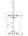
- FIG. 1 is a diagram showing a schematic configuration of a fiber laser system equipped with a light intensity monitor circuit (hereinafter, this light intensity monitor circuit) according to the present embodiment.
- the fiber laser system shown in FIG. 1 includes a fiber laser device 10 including a fiber laser 11, a laser output end 20, and a delivery fiber 30 that connects the fiber laser device 10 and the laser output end 20. Since the fiber laser 11 has a well-known configuration, detailed description of the fiber laser 11 is omitted here.
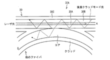
- This light intensity monitor circuit uses a delivery fiber 30 as a double clad fiber, and a slanted fiber Bragg grating (hereinafter referred to as SFBG) 31 and a backward clad mode light detector 32 are provided on the delivery fiber 30. It is configured.
- the SFBG 31 is provided on the output end side of the delivery fiber 30 and couples part of the laser light guided through the core of the delivery fiber 30 to the reverse cladding mode.
- the reverse clad mode light detector (detection means) 32 is a means for detecting the intensity of the reverse clad mode light, and is provided on the input end side of the delivery fiber 30.
- the delivery fiber 30 is covered with a protective hose 33.
- the SFBG 31 is provided on the output end side of the delivery fiber 30 when the SFBG 31 is provided near the output end of the delivery fiber 30 and when the SFBG 31 is connected to the output end of the delivery fiber 30.
- the reverse clad mode light detector 32 is provided on the input end side of the delivery fiber 30 when it is provided as a part near the input end of the delivery fiber 30 and connected to the input end of the delivery fiber 30. And the case where it is done.
- this light intensity monitoring circuit a part of the laser light is detected by returning it from the laser output end 20 side (output end side) of the delivery fiber 30 to the fiber laser device 10 side (input end side), thereby detecting the laser light intensity. And disconnection of the delivery fiber 30 are detected. For this reason, by appropriately setting the reflectance according to the light receiving sensitivity of the light receiving means, it is possible to monitor the laser light intensity even if the laser light has a high output. Further, the laser output end 20 of the delivery fiber 30 becomes larger than necessary, and the communication with the fiber laser device 10 side does not require a complicated configuration. The reason will be described in detail below.
- the delivery fiber 30 is a double clad fiber, and the delivery fiber 30 is made up of the core 30A, the first clad 30B having a lower refractive index than the core 30A, and the first clad 30B.
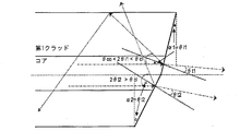
- the SFBG 31 is formed so as to be inclined (slant angle: ⁇ ) from the axis (longitudinal axis) of the optical fiber in a direction perpendicular to the surface where the refractive index rises.
- ⁇ tilt angle
- the coupling from the forward core mode propagating in the forward direction to the backward core mode propagating in the reverse direction is suppressed, and the forward core mode propagating in the forward direction is suppressed. Coupling to the reverse cladding mode propagating in the opposite direction is facilitated.
- the wavelength of the forward core mode coupled to the backward cladding mode is determined by the grating period ( ⁇ ).
- the refractive index n of the core, the wavelength ⁇ B of the laser beam, the grating period ⁇ , and the slant angle ⁇ must satisfy the Bragg condition represented by the following formula.
- L grating length
- ⁇ Core confinement ratio
- ⁇ n Refractive index increase amount
- the light coupled to the backward cladding mode (hereinafter referred to as “reverse cladding mode light”) is confined in the first cladding 30B and propagates in the first cladding 30B in the opposite direction to the laser light propagating through the core.
- the backward clad mode light can be detected by the backward clad mode light detector 32 provided on the input end side of the delivery fiber 30.
- a configuration including a directional coupler 32A and a photodetector 32B (for example, a photodiode) can be given as shown in FIG.
- Directional couplers generally use the phenomenon that light is transferred into the other core as the light propagates when light is incident on only one core of an optical fiber having two adjacent cores. To do.
- the first cladding 30B of the delivery fiber 30 is brought close to the core of another fiber.
- the laser light of the core 30A of the delivery fiber 30 is transmitted as it is, and the backward clad mode light propagating through the first clad 30B from the direction A in FIG. 5 is coupled to another fiber.
- the light coupled to another fiber propagates in the direction B in FIG. 5 and is finally detected by the photodetector 32B.
- the laser light intensity can be detected.
- the refractive index of the core of another fiber is set smaller than the refractive index of the second cladding 30C of the delivery fiber 30.
- FIG. 6 a configuration shown in FIG. 6 may be mentioned.
- the second cladding 30 ⁇ / b> C near the input end of the delivery fiber 30 is removed, and the removed portion and the end of the detection fiber 32 ⁇ / b> C have a high refractive index higher than the first cladding 30 ⁇ / b> B of the delivery fiber 30. It is surrounded by the rate medium 32D. At this time, the end of the detection fiber 32 ⁇ / b> C is made parallel to the delivery fiber 30.
- the light leaking from the vicinity of the input end of the delivery fiber 30 can be coupled to the detection fiber 32C by the high refractive index medium 32D and detected by the photodetector 32B. Even from the above configuration, the laser light intensity can be detected.
- FIG. 12 another configuration example of the backward clad mode light detection unit 32 in the present invention includes the configuration shown in FIG.
- the second cladding 30C near the input end of the double-clad delivery fiber 30 is removed, and the removed portion is surrounded by a high refractive index medium 32D having a higher refractive index than the first cladding 30B.
- a photodetector 32B is arranged inside or outside the high refractive index medium 32D.
- the backward clad mode light scattered by the high refractive index medium 32D can be directly detected on the light receiving surface of the photodetector 32B. Even from the above configuration, the laser light intensity can be detected.
- the above-described three configuration examples in the backward clad mode light detection unit 32 have the following advantages in that the laser light intensity is detected without directly passing the laser light propagating through the core. That is, in the case of using a directional coupler via the propagation light of the core, the ratio of the light coupled for monitoring the laser light may be very small because the laser light has a high output.
- the core of the directional coupler in order to produce such a directional coupler with a low coupling ratio, the core of the directional coupler must be stretched. When the core part is stretched, there is a considerable loss in the stretched part, but the absolute value of the energy that is emitted even with a slight loss due to the high output of the laser light is large and depends on the emitted energy. It is conceivable that the directional coupler is burned out due to heat generation. In the backward clad mode light detector 32 in the present embodiment, since the light of the clad rather than the core is coupled, such a concern is eliminated.
- an optical isolator having an isolation of 30 dB or more may be provided on the output side of the SFBG 31.
- the laser light emitted from the output end is absorbed by the material, but part of it is reflected (the reflectivity varies depending on the material).
- the reflected laser light recombines with the core and the first cladding at the output end and returns to the fiber laser body.
- the backward clad mode detector detects 1) backward clad mode light by SFBG, 2) light coupled to the backward clad mode by Rayleigh scattering, and 3) reflected light from the material.
- all of the lights 1) to 3) have the same wavelength as the laser light.
- the optical isolator is provided to prevent the reflected light from the material from returning to the delivery fiber and to reduce the influence of 3).
- the isolation of 1) +2) at the detector is increased by 1% at the maximum with the isolation of 20 dB.
- the isolation is 30 dB, it is only necessary to increase the maximum by 0.1%. Therefore, even when the reflectance of 1) +2) is set to about 0.5%, it is possible to correctly determine the disconnection detection. .
- the disconnection of the delivery fiber 30 can be determined by a change from the predetermined assumed value of the reflectivity (that is, the reflection amount) of the backward clad mode light. That is, in a state where no disconnection has occurred, it is determined as normal by detecting the intensity of the backward clad mode light according to the laser light intensity and the reflectance of the SFBG. On the other hand, in the state where the disconnection has occurred, Fresnel reflection occurs on the disconnection surface of the delivery fiber 30, so that the intensity of the backward cladding mode light changes, and the disconnection can be determined based on the amount of change.
- the detection means detects the light intensity within the fluctuation of R (X ⁇ x) [W].
- a range having a margin ( ⁇ y: where y> x) having a margin than this range is used as a threshold, and when the detection amount fluctuates more than this threshold, that is, R (X + y) [W] or more or R (X ⁇ y) [ W] It is determined that the wire breaks when the following is reached. Furthermore, by considering the reflected light intensity due to Rayleigh scattering and the temperature dependence of the laser output, the disconnection can be determined more accurately by setting the threshold value.
- FIGS. 8 to 10 are diagrams showing Fresnel reflection in the case where the broken surface (of the core portion) of the fiber is broken at an angle where the angle is different.
- the light propagating through the core is a light beam traveling in parallel to the optical axis of the core.
- the angle ⁇ of the broken plane is an angle formed by the broken plane and a plane perpendicular to the optical axis of the core (or an angle formed by the normal of the broken plane and the optical axis of the core).
- the angle ⁇ of the broken plane is other than that, it is coupled to the reverse core mode (see FIG. 9) or becomes the radiation mode (see FIG. 10).
- the angle ⁇ of the broken plane where the light reflected by Fresnel is coupled to the backward cladding mode is in a range satisfying the following expression (1).
- ⁇ i an incident angle at the time of Fresnel reflection and is equal to the angle of the broken surface.
- ⁇ co is a critical angle determined by the NA (opening) of the core
- ⁇ cl is a critical angle determined by the NA of the first cladding.
- the angle of the disconnected surface coupled to the backward cladding mode ⁇ is about 8.0 ° to about 18.2 °.
- the backward clad mode light detection unit 32 does not detect light due to Fresnel reflection (however, light coupled by the backward clad mode is detected by Rayleigh scattering). Therefore, by making the reflectivity of SFBG 31 larger than the maximum Fresnel reflectivity within the range of the angle of the disconnection plane that can be coupled to the reverse cladding mode by Fresnel reflection, the presence or absence of disconnection due to the change in reflectivity is confirmed. Can be determined.
- the backward cladding mode is entered.
- the angle ⁇ of the broken surface to be joined is about 8.0 ° to about 18.2 °.
- the Fresnel reflectivity at this time is approximately 4% as shown in FIG. 7 when the broken surface that causes Fresnel reflection is the interface between glass and air. That is, it can be considered that the delivery fiber 30 is disconnected when the reflectance of the SFBG 31 in the delivery fiber 30 is larger than 4% and the reflectance is 4% or less.
- FIG. 11 shows a case where the broken surface of the optical fiber is composed of a first broken surface having an angle ⁇ 1 of the broken surface and a second broken surface having an angle ⁇ 2 of the broken surface.
- the first broken surface and the second broken surface are equally divided by a boundary line passing through the center point of the fiber cross section.
- the total Fresnel reflected light in FIG. 11 is equally divided into light that is coupled from the first broken plane to the cladding mode and light that is emitted from the second broken plane to the outside of the optical fiber. To do. Therefore, it is considered that the reflectivity coupled to the cladding mode by total Fresnel reflection at the end face of the optical fiber in this case is about 2%.
- the reflectivity of light coupled to the cladding mode by Fresnel reflection can easily vary from 0 to 4%. Can understand. That is, if the reflectance of SFBG 31 is set to be larger than 4%, the disconnection of the delivery fiber 30 can be reliably detected when the reflectance is 4% or less.
- the reflectance at the broken surface when the optical fiber is broken does not always maintain a constant value. For example, when an optical fiber breaks, a small crack is first generated, and the crack grows to reach a complete break, so the end face shape changes from the initial state of the break to the final break. To do.
- the end face shape changes due to heat generated by the laser beam even after the fiber breaks. If the shape of the end face changes, the reflectivity due to Fresnel reflection fluctuates accordingly. Therefore, even if the reflectivity of SFBG is set within the fluctuation range of Fresnel reflectivity, it is actually possible to detect a fiber breakage. .
- the reflectivity that fluctuates in the fiber disconnection process is detected, and the disconnection is detected when the fluctuation range from the normal time becomes more than a certain level Good.
- the fluctuation range at this time is preferably obtained based on the output stability of the fiber laser. That is, if the ratio of the intensity of the backward clad mode light propagating through the first clad 30B to the intensity of the laser light propagating through the core 30A of the delivery fiber 30 is obtained, the change in reflectance is defined as the fluctuation range from the normal time Can be detected.
- the reflectance of SFBG needs to be larger than the coupling rate to the backward cladding mode due to Rayleigh scattering.
- the reflectivity indicates the ratio of light reflected as a backward cladding mode with respect to the original laser light
- the coupling ratio indicates the ratio of light coupled to the backward cladding mode with respect to the original laser light. It is shown. Even if the fiber is disconnected before the SFBG, if the Fresnel reflection is not coupled to the cladding mode light at all, the backward cladding mode light is only due to Rayleigh scattering.
- the disconnection of the fiber can be detected even if the reflectivity of SFBG is set within the fluctuation range of the Fresnel reflectivity, but the disconnection of the SFBG 31 is larger than the reflectivity of Fresnel reflection. Is preferable because it can be reliably detected. And even if it is a case where the reflectance of SFBG is set larger than a Fresnel reflectance, if the Fresnel reflectance can be made small, the reflectance of SFBG can also be made small. If the reflectance of the SFBG is reduced, the ratio of the laser light taken out for monitoring is reduced, so that the ratio of the output laser light can be increased, and as a result, the output efficiency of the laser is increased.
- the Fresnel reflection can be reduced by making the refractive index of the medium contacting the fiber end face close to the refractive index of the core of the optical fiber (here, glass; refractive index 1.5).
- the medium that contacts the fiber end face when disconnected is air (refractive index 1).
- this medium is water (refractive index 1.33), for example, FIG.
- the Fresnel reflectance can be reduced to 1% or less.
- the protective hose 33 may be filled with water and the periphery of the delivery fiber 30 may be surrounded by water.
- the medium brought into contact with the fiber end face when disconnected is not limited to water as described above, and may be a fluid medium having a refractive index closer to the refractive index of the core of the optical fiber than air.
- the light intensity at the time of backward clad mode light detection also changes. Therefore, if the ratio between the laser light intensity and the light intensity at the time of detecting the backward clad mode light is examined in advance, the light at the time of detection can be distinguished by reflected light by SFBG, Fresnel reflected light, and reflected light by Rayleigh scattering. .
- the light intensity monitoring circuit of the present invention includes a delivery fiber composed of a double clad fiber in which the periphery of the core is covered with the first cladding and the periphery of the first cladding is covered with the second cladding, Reflecting means provided on the output end side for reflecting a part of the laser light propagating through the core of the delivery fiber and coupling to the backward clad mode propagating through the first cladding in the reverse direction; And detecting means for detecting the intensity of the backward clad mode light coupled to the backward clad mode by the reflecting means.
- a part of the laser light propagating through the core is returned to the input side as backward clad mode light by the reflecting means provided on the output end side of the delivery fiber, and provided on the input end side of the delivery fiber.
- the intensity of the backward clad mode light is detected by the above detection means. For this reason, it is not necessary to detect the intensity of the laser beam emitted from the output end and the detection of the disconnection of the delivery fiber on the output end side of the delivery fiber, and the output end becomes larger than necessary, Can be prevented from having a complicated configuration.
- the reflecting means is preferably a slanted fiber Bragg grating. According to said structure, the said reflection means can be formed easily, without making the structure of a delivery fiber complicated.
- the detecting means receives a directional coupler that couples only the backward clad mode light propagating through the first clad, and the backward clad mode light coupled by the directional coupler. And a photodetector.
- the detection means has a refractive index higher than that of the portion where the second cladding in the vicinity of the input end of the delivery fiber is removed, the detection fiber, and the first cladding of the delivery fiber. Light for leaking from the portion of the delivery fiber from which the second cladding has been removed by surrounding the portion of the delivery fiber from which the second cladding has been removed and the end of the detection fiber.
- a high refractive index medium coupled to the fiber and a photodetector for receiving the light coupled to the detection fiber can be used.
- the detection means is a portion in which the second cladding in the vicinity of the input end of the delivery fiber is removed, and a medium having a higher refractive index than the first cladding of the delivery fiber,
- a high refractive index medium that scatters light leaking from the portion of the delivery fiber from which the second cladding has been removed by surrounding the portion of the delivery fiber from which the second cladding has been removed, and is scattered by the high refractive index medium. It can be set as the structure which consists of a photodetector which receives light.
- the laser beam intensity can be detected without directly passing the laser beam propagating through the core.
- the light intensity monitor circuit can be configured to include an optical isolator on the output end side of the reflecting means.
- the reflectivity of the reflecting means may be larger than the coupling rate to the reverse cladding mode of Fresnel reflection occurring at the disconnection interface of the delivery fiber.
- the said detection means can detect the disconnection of the said delivery fiber reliably, when the reflectance of the reverse clad mode light detected becomes smaller than the reflectance of the said reflection means.
- the delivery fiber is disposed in a protective hose, and the protective hose is a fluid medium having a refractive index closer to the refractive index of the core of the delivery fiber than air. Can be configured to be satisfied.
- the medium that comes into contact with the fiber end surface when disconnected is the fluid medium. Since the fluid medium has a refractive index that is closer to the refractive index of the core of the delivery fiber than air, the Fresnel reflection on the broken surface is smaller than when the medium that contacts the fiber end surface when broken is air. it can. If the Fresnel reflection at the disconnection surface is reduced, disconnection can be detected even if the reflectance of the reflecting means is reduced. Therefore, the ratio of laser light to be extracted for monitoring is reduced, and the ratio of output laser light is reduced. As a result, the output efficiency of the laser can be increased.
- the reflectance of the reflecting means is greater than the coupling ratio of Rayleigh scattering coupled to the backward cladding mode of the delivery fiber, and the detecting means propagates through the first cladding. It can be set as the structure which detects the time fluctuation
- the reflectance of the reflecting means is the Fresnel reflectance. Even if it is set within the fluctuation range, the disconnection can be detected when the fluctuation range from the normal time becomes equal to or larger than a certain value while detecting the temporal fluctuation. That is, by setting the reflectivity of the reflecting means within the fluctuation range of the Fresnel reflectivity, the ratio of the laser light taken out for monitoring can be reduced, and the ratio of the output laser light can be increased. Output efficiency can be increased.
- the present invention can provide a light intensity monitor capable of detecting laser light intensity and disconnection even when high output light propagates through a delivery fiber, and can be used in a fiber laser system.
- Fiber laser apparatus 11 Fiber laser 20 Laser output end 30 Delivery fiber 30A Core 30B 1st clad 30C 2nd clad 31 Slanted fiber Bragg grating (reflection means) 32 Reverse clad mode light detector (detector) 32A Directional coupler 32B Photodetector 32C Detection fiber 32D High refractive index medium 33 Protective hose
Landscapes
- Physics & Mathematics (AREA)
- Optics & Photonics (AREA)
- General Physics & Mathematics (AREA)
- Engineering & Computer Science (AREA)
- Spectroscopy & Molecular Physics (AREA)
- Mechanical Engineering (AREA)
- Plasma & Fusion (AREA)
- Chemical & Material Sciences (AREA)
- Analytical Chemistry (AREA)
- Lasers (AREA)
- Optical Couplings Of Light Guides (AREA)
- Photometry And Measurement Of Optical Pulse Characteristics (AREA)
- Testing Of Optical Devices Or Fibers (AREA)
- Optical Fibers, Optical Fiber Cores, And Optical Fiber Bundles (AREA)
Abstract
A fiber laser system is comprised of: a fiber laser apparatus (10) further comprising a fiber laser (11); a laser output-end section (20); and a delivery fiber (30) that connects the fiber laser apparatus (10) and the laser output-end section (20). The delivery fiber (30) is comprised of a double-clad fiber. An SFBG (31), which conjoins with a backward clad mode wherein a portion of laser beams propagating through the core of the delivery fiber (30) is reflected and propagated in the opposite direction through a first clad, is formed at the output-end side of the delivery fiber (30). Further, a backward-clad-mode light detection unit (32), which detects the intensity of backward-clad-mode light that is generated as a result of the conjoining of the SFBG (31) with the backward clad mode, is formed at the input-end side of the delivery fiber (30).
Description
本発明は、ファイバレーザの光強度モニタ方法に関するものであり、特にデリバリファイバに高出力光が伝播するような場合でも、光強度および断線の検出ができる光強度モニタに関する。
The present invention relates to a light intensity monitoring method for a fiber laser, and more particularly to a light intensity monitor capable of detecting light intensity and disconnection even when high output light propagates through a delivery fiber.
レーザ光を用いて材料加工する場合、加工する材料によっては数ワット程度のレーザ出力で十分な場合もあるが、厚い金属を加工するような場合はキロワット級のレーザ出力を要する。金属加工用レーザとしては、YAGレーザ、CO2レーザ、エキシマレーザ、ファイバレーザなどがある。このうちファイバレーザは高効率・高利得・良好なビーム品質であり、要素のほとんどが光ファイバで構成されていることからメンテナンス性も良いレーザ光源として注目されている。
When processing a material using laser light, a laser output of several watts may be sufficient depending on the material to be processed, but when processing a thick metal, a laser output of a kilowatt class is required. Examples of the metal processing laser include a YAG laser, a CO 2 laser, an excimer laser, and a fiber laser. Of these, the fiber laser has high efficiency, high gain, and good beam quality, and since most of the elements are made of optical fiber, it is attracting attention as a laser light source with good maintainability.
ファイバレーザでは、レーザ光が伝播する経路も全て光ファイバであり、例えばレーザの出力端部とファイバレーザ本体を結ぶデリバリファイバの長さを自由に変えることもできるため、本体を移動させること無く、出力端部の位置だけ移動させて材料加工することができるといった利点もある。
In the fiber laser, all the paths through which the laser light propagates are also optical fibers.For example, the length of the delivery fiber connecting the laser output end and the fiber laser main body can be freely changed. There is also an advantage that the material can be processed by moving only the position of the output end.
このことから、デリバリファイバはある程度自由に動かせる必要があるため、装置本体に比べるとファイバの断線確率は高くなる虞がある。デリバリファイバで断線が生じた場合、高出力の光が断線箇所から放射されてしまい、その放射された光がデリバリファイバを保護しているホース等を貫通する場合がある。この場合、周囲に光が漏れ出してしまう虞がある。
For this reason, since the delivery fiber needs to be able to move freely to some extent, there is a possibility that the disconnection probability of the fiber is higher than that of the apparatus main body. When a disconnection occurs in the delivery fiber, high output light may be emitted from the disconnection point, and the emitted light may pass through a hose or the like that protects the delivery fiber. In this case, there is a possibility that light leaks out to the surroundings.
このため、安全性の観点から、デリバリファイバの断線を検出する必要がある。また、加工を安定させるためには、照射されるレーザ出力の安定性も重要になり、一定のレーザ出力が供給できるような光強度モニタ回路が必要となる。
For this reason, it is necessary to detect disconnection of the delivery fiber from the viewpoint of safety. Further, in order to stabilize the processing, the stability of the irradiated laser output is also important, and a light intensity monitor circuit capable of supplying a constant laser output is required.
従来技術としては、特許文献1に示されたように、光ファイバのコア部にスラント型ブラッググレーティングを設けてコアの導波光の一部を光ファイバの外部に放射し、放射された光を受光素子により検出する光モニタデバイスがある。また、特許文献2では、ファイバの融着点から漏れる散乱光を融着点近傍の別のファイバで検出する方法が開示されている。
As a prior art, as shown in Patent Document 1, a slanted Bragg grating is provided in the core portion of the optical fiber to radiate a part of the guided light of the core to the outside of the optical fiber, and receive the emitted light. There are optical monitoring devices that detect by element. Patent Document 2 discloses a method of detecting scattered light leaking from a fiber fusion point with another fiber in the vicinity of the fusion point.
特許文献1では、光ファイバの出力端側に設けられたスラント型ブラッググレーティングにより、コアを導波する光の一部を光ファイバの外部へと放射し、放射された光を受光素子により検出することで光強度をモニタしている。しかしながら、このような構成を採用すると、受光素子等を出力端側に設ける必要があり、出力端部が大きくなるといった問題がある。さらに、本体側との通信も複雑な構成(例えば保護ホース内に受光素子にて生成された光電流を伝送するための電気配線を通すなど)になってしまうといった問題もある。
In Patent Document 1, a slant Bragg grating provided on the output end side of an optical fiber emits part of the light guided through the core to the outside of the optical fiber, and the emitted light is detected by the light receiving element. In this way, the light intensity is monitored. However, when such a configuration is adopted, it is necessary to provide a light receiving element or the like on the output end side, and there is a problem that the output end portion becomes large. Furthermore, there is a problem that communication with the main body side also has a complicated configuration (for example, an electric wiring for transmitting a photocurrent generated by the light receiving element is passed through the protective hose).
また、特許文献2では、融着点からの散乱光を別の光ファイバを通してモニタしているが、フレキシビリティを求められるデリバリファイバ中に融着点や補強部があることは望ましくない。また、デリバリファイバの出力側にこのような光モニタデバイスを配置する場合は、特許文献1と同様に、出力端部が大きくなるといった問題がある。
In Patent Document 2, scattered light from the fusion point is monitored through another optical fiber. However, it is not desirable that the delivery fiber that requires flexibility has a fusion point or a reinforcing part. Further, when such an optical monitor device is arranged on the output side of the delivery fiber, there is a problem that the output end becomes large as in Patent Document 1.
本願発明は、上記の課題に鑑みてなされたものであり、出力端部に複雑な構成を必要とせず、デリバリファイバを伝播するレーザ光の光強度を高精度に検出し、レーザ光が伝播する経路の断線も検出できる光強度モニタ回路を提供することを目的としている。
The present invention has been made in view of the above problems, and does not require a complicated configuration at the output end, detects the light intensity of the laser light propagating through the delivery fiber with high accuracy, and propagates the laser light. An object of the present invention is to provide a light intensity monitor circuit capable of detecting disconnection of a path.
上記の課題を解決するために、本発明の光強度モニタ回路は、コアの周囲を第1クラッドで覆い、さらに第1クラッドの周囲を第2クラッドで覆ったダブルクラッドファイバからなるデリバリファイバと、上記デリバリファイバの出力端側に設けられ、上記デリバリファイバの上記コアを伝播するレーザ光の一部を反射して、上記第1クラッドを逆方向に伝播する後進クラッドモードへ結合する反射手段と、上記デリバリファイバの入力端側に設けられ、上記反射手段によって後進クラッドモードへ結合された後進クラッドモード光の強度を検出する検出手段とを備えたことを特徴としている。
In order to solve the above problems, a light intensity monitor circuit according to the present invention includes a delivery fiber comprising a double clad fiber in which a core is covered with a first clad and a first clad is covered with a second clad. Reflecting means provided on the output end side of the delivery fiber to reflect a part of the laser light propagating through the core of the delivery fiber and to couple to the backward clad mode propagating in the first clad in the opposite direction; And detecting means for detecting the intensity of the backward clad mode light, which is provided on the input end side of the delivery fiber and is coupled to the backward clad mode by the reflecting means.
上記の構成によれば、コアを伝播するレーザ光の一部は、上記デリバリファイバの出力端側に設けられた反射手段によって後進クラッドモード光として入力側に戻し、デリバリファイバの入力端側に設けられた上記検出手段によってこの後進クラッドモード光の強度を検出される。このため、出力端部から出射されるレーザ光強度の検出やデリバリファイバの断線の検出をデリバリファイバの出力端側で行なう必要が無くなり、出力端部が必要以上に大きくなることや、本体側との通信が複雑な構成となることを防止できる。
According to the above configuration, a part of the laser light propagating through the core is returned to the input side as backward clad mode light by the reflecting means provided on the output end side of the delivery fiber, and provided on the input end side of the delivery fiber. The intensity of the backward clad mode light is detected by the above detection means. For this reason, it is not necessary to detect the intensity of the laser beam emitted from the output end and the detection of the disconnection of the delivery fiber on the output end side of the delivery fiber, and the output end becomes larger than necessary, Can be prevented from having a complicated configuration.
本発明の光強度モニタ回路では、出力端部から出射されるレーザ光強度の検出やデリバリファイバの断線の検出をデリバリファイバの出力端側で行なう必要が無くなり、出力端部が必要以上に大きくなることや、本体側との通信が複雑な構成となることを防止できる。
In the light intensity monitor circuit of the present invention, it is not necessary to detect the intensity of the laser light emitted from the output end and the detection of the disconnection of the delivery fiber, and the output end becomes larger than necessary. In addition, it is possible to prevent the communication with the main body side from being complicated.
以下、本発明の実施の形態について、詳細に説明する。図1は、本実施の形態に係る光強度モニタ回路(以下、本光強度モニタ回路)を搭載したファイバレーザシステムの概略構成を示す図である。
Hereinafter, embodiments of the present invention will be described in detail. FIG. 1 is a diagram showing a schematic configuration of a fiber laser system equipped with a light intensity monitor circuit (hereinafter, this light intensity monitor circuit) according to the present embodiment.
図1に示すファイバレーザシステムは、ファイバレーザ11を含むファイバレーザ装置10と、レーザ出力端部20と、ファイバレーザ装置10およびレーザ出力端部20を結ぶデリバリファイバ30とから構成されている。尚、ファイバレーザ11は周知の構成であるため、ここではファイバレーザ11の詳細な説明を省略する。
The fiber laser system shown in FIG. 1 includes a fiber laser device 10 including a fiber laser 11, a laser output end 20, and a delivery fiber 30 that connects the fiber laser device 10 and the laser output end 20. Since the fiber laser 11 has a well-known configuration, detailed description of the fiber laser 11 is omitted here.
本光強度モニタ回路は、デリバリファイバ30をダブルクラッドファイバとし、デリバリファイバ30に、スラントされたファイバブラッググレーティング(以下、SFBG;反射手段)31と、後進クラッドモード光検出部32とを設けることによって構成されている。SFBG31は、デリバリファイバ30の出力端側に設けられ、デリバリファイバ30のコアを導波するレーザ光の一部を後進クラッドモードへ結合させる。後進クラッドモード光検出部(検出手段)32は、後進クラッドモード光の強度を検出する手段であり、デリバリファイバ30の入力端側に設けられている。さらに、デリバリファイバ30は、保護ホース33によって覆われている。尚、SFBG31がデリバリファイバ30の出力端側に設けられるとは、SFBG31がデリバリファイバ30の出力端付近にその一部として設けられる場合と、SFBG31がデリバリファイバ30の出力端部に接続される場合とを含むものとする。同様に、後進クラッドモード光検出部32がデリバリファイバ30の入力端側に設けられるとは、デリバリファイバ30の入力端付近にその一部として設けられる場合と、デリバリファイバ30の入力端部に接続される場合とを含むものとする。
This light intensity monitor circuit uses a delivery fiber 30 as a double clad fiber, and a slanted fiber Bragg grating (hereinafter referred to as SFBG) 31 and a backward clad mode light detector 32 are provided on the delivery fiber 30. It is configured. The SFBG 31 is provided on the output end side of the delivery fiber 30 and couples part of the laser light guided through the core of the delivery fiber 30 to the reverse cladding mode. The reverse clad mode light detector (detection means) 32 is a means for detecting the intensity of the reverse clad mode light, and is provided on the input end side of the delivery fiber 30. Furthermore, the delivery fiber 30 is covered with a protective hose 33. The SFBG 31 is provided on the output end side of the delivery fiber 30 when the SFBG 31 is provided near the output end of the delivery fiber 30 and when the SFBG 31 is connected to the output end of the delivery fiber 30. And Similarly, the reverse clad mode light detector 32 is provided on the input end side of the delivery fiber 30 when it is provided as a part near the input end of the delivery fiber 30 and connected to the input end of the delivery fiber 30. And the case where it is done.
本光強度モニタ回路では、レーザ光の一部をデリバリファイバ30のレーザ出力端部20側(出力端側)からファイバレーザ装置10側(入力端側)に戻して検出することで、レーザ光強度の検出およびデリバリファイバ30の断線の検出を行っている。このため、受光手段の受光感度に応じて、反射率を適切に設定することにより、レーザ光が高出力なものであってもレーザ光強度のモニタが可能である。また、デリバリファイバ30のレーザ出力端部20が必要以上に大きくなることや、ファイバレーザ装置10側との通信も複雑な構成が不用になる。その理由を以下に詳細に説明する。
In this light intensity monitoring circuit, a part of the laser light is detected by returning it from the laser output end 20 side (output end side) of the delivery fiber 30 to the fiber laser device 10 side (input end side), thereby detecting the laser light intensity. And disconnection of the delivery fiber 30 are detected. For this reason, by appropriately setting the reflectance according to the light receiving sensitivity of the light receiving means, it is possible to monitor the laser light intensity even if the laser light has a high output. Further, the laser output end 20 of the delivery fiber 30 becomes larger than necessary, and the communication with the fiber laser device 10 side does not require a complicated configuration. The reason will be described in detail below.
本光強度モニタ回路は、図2に示すように、デリバリファイバ30をダブルクラッドファイバとしており、デリバリファイバ30は、コア30A、コア30Aよりも屈折率の低い第1クラッド30B、第1クラッド30Bよりも屈折率の低い第2クラッド30Cを有している。すなわち、デリバリファイバ30は、コア30Aの周囲を第1クラッド30Bで覆い、さらに第1クラッド30Bの周囲を第2クラッド30Cで覆っている。さらに、デリバリファイバ30は、コア30AにSFBG31を設けている。
In the present light intensity monitor circuit, as shown in FIG. 2, the delivery fiber 30 is a double clad fiber, and the delivery fiber 30 is made up of the core 30A, the first clad 30B having a lower refractive index than the core 30A, and the first clad 30B. Has a second clad 30C having a low refractive index. That is, the delivery fiber 30 covers the periphery of the core 30A with the first cladding 30B, and further covers the periphery of the first cladding 30B with the second cladding 30C. Further, the delivery fiber 30 is provided with an SFBG 31 on the core 30A.
SFBG31は、図3に示すように、屈折率上昇の生じている面に垂直な方向を光ファイバの軸(長手軸)から傾ける(スラント角:θ)ようにして形成されている。SFBG31では、屈折率上昇の生じている面を傾けることによって、順方向に伝播する前進コアモードから、逆方向に伝播する後進コアモードへの結合が抑制され、順方向に伝播する前進コアモードから逆方向に伝播する後進クラッドモードへの結合が助長される。尚、後進クラッドモードに結合する前進コアモードの波長は、グレーティング周期(Λ)で決まる。
As shown in FIG. 3, the SFBG 31 is formed so as to be inclined (slant angle: θ) from the axis (longitudinal axis) of the optical fiber in a direction perpendicular to the surface where the refractive index rises. In SFBG31, by tilting the surface where the refractive index rises, the coupling from the forward core mode propagating in the forward direction to the backward core mode propagating in the reverse direction is suppressed, and the forward core mode propagating in the forward direction is suppressed. Coupling to the reverse cladding mode propagating in the opposite direction is facilitated. Note that the wavelength of the forward core mode coupled to the backward cladding mode is determined by the grating period (Λ).
尚、SFBG31によって後進クラッドモードへ結合させるためには、コアの屈折率n,レーザ光の波長λB,グレーティング周期Λ,およびスラント角θが、下記式で示されるブラッグ条件を満たす必要がある。
In order to couple to the backward clad mode by the SFBG 31, the refractive index n of the core, the wavelength λ B of the laser beam, the grating period Λ, and the slant angle θ must satisfy the Bragg condition represented by the following formula.
N×(λB/n)=2Λcosθ(Nは整数)
また、SFBG31による反射率Rとスラント角θとの関係は下記式によって表される。 N × (λ B / n) = 2Λ cos θ (N is an integer)
Further, the relationship between the reflectance R and the slant angle θ by theSFBG 31 is expressed by the following equation.
また、SFBG31による反射率Rとスラント角θとの関係は下記式によって表される。 N × (λ B / n) = 2Λ cos θ (N is an integer)
Further, the relationship between the reflectance R and the slant angle θ by the
R=tanh2(πLΔnη/λB)
=tanh2((πLΔnη/2nΛcosθ)×N)
但し、L:グレーティング長,
η:コアの閉じ込め率
Δn:屈折率増加量
である。 R = tanh 2 (πLΔnη / λ B )
= Tanh 2 ((πLΔnη / 2nΛcosθ) × N)
Where L: grating length,
η: Core confinement ratio Δn: Refractive index increase amount.
=tanh2((πLΔnη/2nΛcosθ)×N)
但し、L:グレーティング長,
η:コアの閉じ込め率
Δn:屈折率増加量
である。 R = tanh 2 (πLΔnη / λ B )
= Tanh 2 ((πLΔnη / 2nΛcosθ) × N)
Where L: grating length,
η: Core confinement ratio Δn: Refractive index increase amount.
後進クラッドモードへ結合された光(以下「後進クラッドモード光」と呼ぶ)は、第1クラッド30B内に閉じ込められ、コアを伝播するレーザ光とは逆方向に第1クラッド30B内を伝播する。その後進クラッドモード光は、デリバリファイバ30の入力端側に設けられた後進クラッドモード光検出部32によって、そのレーザ光強度を検出できる。
The light coupled to the backward cladding mode (hereinafter referred to as “reverse cladding mode light”) is confined in the first cladding 30B and propagates in the first cladding 30B in the opposite direction to the laser light propagating through the core. The backward clad mode light can be detected by the backward clad mode light detector 32 provided on the input end side of the delivery fiber 30.
後進クラッドモード光検出部32の一構成例としては、図4に示すように、方向性結合器32Aと光検出器32B(例えば、フォトダイオード)とからなる構成が挙げられる。方向性結合器は、一般には二つの近接したコアを持つ光ファイバの片方のコアのみに光を入射した場合に、光の伝播に伴い、もう片方のコア内にも光が移行する現象を利用するものである。但し、ここで用いる方向性結合器32Aは、図5に示すように、デリバリファイバ30の第1クラッド30Bを別のファイバのコアに近接させている。このため、デリバリファイバ30のコア30Aのレーザ光はそのまま透過し、図5中のAの方向より第1クラッド30Bを伝播する後進クラッドモード光を別のファイバへ結合させている。別のファイバに結合された光は、図5中のBの方向へ伝播し、最終的に光検出器32Bによって検出される。以上の構成により、レーザ光強度の検出が可能となる。尚、方向性結合器32Aでは、別のファイバのコアの屈折率は、デリバリファイバ30の第2クラッド30Cの屈折率よりも小さく設定される。
As an example of the configuration of the backward clad mode light detection unit 32, a configuration including a directional coupler 32A and a photodetector 32B (for example, a photodiode) can be given as shown in FIG. Directional couplers generally use the phenomenon that light is transferred into the other core as the light propagates when light is incident on only one core of an optical fiber having two adjacent cores. To do. However, in the directional coupler 32A used here, as shown in FIG. 5, the first cladding 30B of the delivery fiber 30 is brought close to the core of another fiber. For this reason, the laser light of the core 30A of the delivery fiber 30 is transmitted as it is, and the backward clad mode light propagating through the first clad 30B from the direction A in FIG. 5 is coupled to another fiber. The light coupled to another fiber propagates in the direction B in FIG. 5 and is finally detected by the photodetector 32B. With the above configuration, the laser light intensity can be detected. In the directional coupler 32A, the refractive index of the core of another fiber is set smaller than the refractive index of the second cladding 30C of the delivery fiber 30.
また、本発明における後進クラッドモード光検出部32の他の構成例としては、図6に示す構成が挙げられる。図6の構成では、デリバリファイバ30の入力端付近の第2クラッド30Cを除去し、その除去部分と検出用ファイバ32Cの端部をデリバリファイバ30の第1クラッド30Bよりも屈折率の高い高屈折率媒体32Dで囲んでいる。この時、検出用ファイバ32Cの端部はデリバリファイバ30と平行にされる。これにより、デリバリファイバ30の入力端付近から漏れ出した光を、高屈折率媒体32Dによって検出用ファイバ32Cに結合させて、光検出器32Bによって検出することが可能である。以上の構成からでも、レーザ光強度の検出が可能となる。
Further, as another configuration example of the backward clad mode light detection unit 32 in the present invention, a configuration shown in FIG. 6 may be mentioned. In the configuration of FIG. 6, the second cladding 30 </ b> C near the input end of the delivery fiber 30 is removed, and the removed portion and the end of the detection fiber 32 </ b> C have a high refractive index higher than the first cladding 30 </ b> B of the delivery fiber 30. It is surrounded by the rate medium 32D. At this time, the end of the detection fiber 32 </ b> C is made parallel to the delivery fiber 30. Thereby, the light leaking from the vicinity of the input end of the delivery fiber 30 can be coupled to the detection fiber 32C by the high refractive index medium 32D and detected by the photodetector 32B. Even from the above configuration, the laser light intensity can be detected.
また、本発明における後進クラッドモード光検出部32のさらに他の構成例としては、図12に示す構成が挙げられる。図12の構成では、ダブルクラッドのデリバリファイバ30の入力端付近の第2クラッド30Cを除去し、その除去部分を第1クラッド30Bよりも屈折率の高い高屈折率媒体32Dで囲んでいる。さらに、高屈折率媒体32Dの中または外に光検出器32Bを配置している。これにより、高屈折率媒体32Dにより散乱する後進クラッドモード光を光検出器32Bの受光面に直接検出させることが可能である。以上の構成からでも、レーザ光強度の検出が可能となる。
Further, another configuration example of the backward clad mode light detection unit 32 in the present invention includes the configuration shown in FIG. In the configuration of FIG. 12, the second cladding 30C near the input end of the double-clad delivery fiber 30 is removed, and the removed portion is surrounded by a high refractive index medium 32D having a higher refractive index than the first cladding 30B. Further, a photodetector 32B is arranged inside or outside the high refractive index medium 32D. Thereby, the backward clad mode light scattered by the high refractive index medium 32D can be directly detected on the light receiving surface of the photodetector 32B. Even from the above configuration, the laser light intensity can be detected.
後進クラッドモード光検出部32における上述の3つの構成例は、コアを伝播するレーザ光を直接介さずにレーザ光強度を検出している点で以下のメリットを有する。すなわち、コアの伝播光を介した方向性結合器を用いる場合、レーザ光が高出力であることからレーザ光のモニタのために結合される光の割合は非常に小さくてよい。しかしながら、そのような結合比の小さい方向性結合器を作製するには、方向性結合器のコア部を延伸させなければならない。コア部を延伸させた場合には、少なからず延伸部での損失が生じるが、レーザ光が高出力であるが故に僅かな損失でも放出されるエネルギの絶対値は大きく、その放出されたエネルギによる発熱で方向性結合器を焼損させてしまうことが考えられる。本実施の形態における後進クラッドモード光検出部32では、コアではなくクラッドの光を結合させているため、このような心配は無くなる。
The above-described three configuration examples in the backward clad mode light detection unit 32 have the following advantages in that the laser light intensity is detected without directly passing the laser light propagating through the core. That is, in the case of using a directional coupler via the propagation light of the core, the ratio of the light coupled for monitoring the laser light may be very small because the laser light has a high output. However, in order to produce such a directional coupler with a low coupling ratio, the core of the directional coupler must be stretched. When the core part is stretched, there is a considerable loss in the stretched part, but the absolute value of the energy that is emitted even with a slight loss due to the high output of the laser light is large and depends on the emitted energy. It is conceivable that the directional coupler is burned out due to heat generation. In the backward clad mode light detector 32 in the present embodiment, since the light of the clad rather than the core is coupled, such a concern is eliminated.
また、上記ファイバレーザシステムでは、SFBG31よりも出力側にアイソレーション30dB以上の光アイソレータを設けても良い。
In the fiber laser system, an optical isolator having an isolation of 30 dB or more may be provided on the output side of the SFBG 31.
実際にファイバレーザ装置で材料加工を行う場合、出力端部から出射されたレーザ光は材料で吸収されるが、一部は反射される(反射率は材料によって異なる)。反射したレーザ光は、出力端部でコア及び第1クラッドに再結合してファイバレーザ本体へと戻る。この場合、後進クラッドモード検出器としては、1)SFBGによる後進クラッドモード光、2)レイリー散乱によって後進クラッドモードに結合した光、さらに3)材料からの反射光、が検出されることになる。しかも、上記1)~3)の光は、すべてレーザ光と同じ波長となる。
When actually processing a material with a fiber laser device, the laser light emitted from the output end is absorbed by the material, but part of it is reflected (the reflectivity varies depending on the material). The reflected laser light recombines with the core and the first cladding at the output end and returns to the fiber laser body. In this case, the backward clad mode detector detects 1) backward clad mode light by SFBG, 2) light coupled to the backward clad mode by Rayleigh scattering, and 3) reflected light from the material. In addition, all of the lights 1) to 3) have the same wavelength as the laser light.
よって、上記3)の光が検出される場合には、通常の1)+2)の反射量よりも大きな反射光量を検出してしまうため、断線していなくとも誤って断線と判断してしまう事が予想される。そのため、3)の影響を極力減らす必要がある。光アイソレータは、材料からの反射光をデリバリファイバに戻ることを阻止し、3)の影響を減らすために設けられるものである。材料からの反射光が鏡面反射(反射率が100%)で戻ってきた場合、アイソレーション20dBでは検出器における1)+2)の反射率が最大1%大きくなってしまう。アイソレーション30dBとした場合は、最大でも0.1%大きくなるだけで済むため、1)+2)の反射率を例え0.5%程度に設けた場合であっても正しく断線検知の判断ができる。
Therefore, when the light of 3) above is detected, the amount of reflected light that is larger than the normal amount of reflection of 1) + 2) is detected, so even if it is not disconnected, it may be erroneously determined to be disconnected. Is expected. Therefore, it is necessary to reduce the influence of 3) as much as possible. The optical isolator is provided to prevent the reflected light from the material from returning to the delivery fiber and to reduce the influence of 3). When the reflected light from the material returns by specular reflection (reflectance is 100%), the isolation of 1) +2) at the detector is increased by 1% at the maximum with the isolation of 20 dB. When the isolation is 30 dB, it is only necessary to increase the maximum by 0.1%. Therefore, even when the reflectance of 1) +2) is set to about 0.5%, it is possible to correctly determine the disconnection detection. .
続いて、デリバリファイバ30の断線検出方法について説明する。デリバリファイバ30の断線は、後進クラッドモード光の反射率(すなわち、反射量)の予め決められた想定値からの変化によって判断することができる。すなわち、断線が生じていない状態では、レーザ光強度とSFBGの反射率に応じた後進クラッドモード光の強度が検出されることで正常と判断される。一方、断線が生じた状態では、デリバリファイバ30の断線面でフレネル反射が生じることから、後進クラッドモード光の強度に変化が生じ、この変化量によって断線を判断することが可能である。
Subsequently, a method for detecting disconnection of the delivery fiber 30 will be described. The disconnection of the delivery fiber 30 can be determined by a change from the predetermined assumed value of the reflectivity (that is, the reflection amount) of the backward clad mode light. That is, in a state where no disconnection has occurred, it is determined as normal by detecting the intensity of the backward clad mode light according to the laser light intensity and the reflectance of the SFBG. On the other hand, in the state where the disconnection has occurred, Fresnel reflection occurs on the disconnection surface of the delivery fiber 30, so that the intensity of the backward cladding mode light changes, and the disconnection can be determined based on the amount of change.
例えば、レーザ出力がX[W]でSFBGの反射率をRとした場合、後進クラッドモード光強度としてはRX[W]となる。この光すべてが検出手段で検出されるとした場合、レーザ光がある程度変動(X±x[W])すると検出手段ではR(X±x)[W]の変動内で光強度が検出される。この範囲よりもマージンをもった範囲(±y:ただしy>x)を閾値とし、この閾値よりも検出量が変動した場合、すなわちR(X+y)[W]以上またはR(X-y)[W]以下になった場合に断線と判断する。さらに、レイリー散乱による反射光強度およびレーザ出力の温度依存性も考慮して、上記閾値を設定することにより、より的確に断線を判断することができる。
For example, when the laser output is X [W] and the reflectance of SFBG is R, the backward clad mode light intensity is RX [W]. Assuming that all of this light is detected by the detection means, when the laser light changes to some extent (X ± x [W]), the detection means detects the light intensity within the fluctuation of R (X ± x) [W]. . A range having a margin (± y: where y> x) having a margin than this range is used as a threshold, and when the detection amount fluctuates more than this threshold, that is, R (X + y) [W] or more or R (X−y) [ W] It is determined that the wire breaks when the following is reached. Furthermore, by considering the reflected light intensity due to Rayleigh scattering and the temperature dependence of the laser output, the disconnection can be determined more accurately by setting the threshold value.
後進クラッドモード光の検出結果からデリバリファイバ30が断線しているか否かを判別する方法についてより詳細に説明すると以下の通りである。
The method for determining whether or not the delivery fiber 30 is disconnected from the detection result of the backward clad mode light will be described in more detail as follows.
デリバリファイバ30が断線した時、断線したファイバの断面ではフレネル反射が生じる。フレネル反射によってクラッドモードに結合される光の割合は、断線したファイバの端面状態によって変化する。図8~10は、ファイバの(コア部の)断線面が一定となる角度で断線した場合であって、その角度がそれぞれ異なる時のフレネル反射を示す図である。尚、ここでは、説明を簡単にするため、コアを伝播される光は、コアの光軸に対して平行に進む光線として仮定している。
When the delivery fiber 30 is disconnected, Fresnel reflection occurs in the section of the disconnected fiber. The proportion of light coupled to the cladding mode by Fresnel reflection varies with the end face condition of the disconnected fiber. FIGS. 8 to 10 are diagrams showing Fresnel reflection in the case where the broken surface (of the core portion) of the fiber is broken at an angle where the angle is different. Here, in order to simplify the explanation, it is assumed that the light propagating through the core is a light beam traveling in parallel to the optical axis of the core.
図8に示すように、断線面の角度αがある範囲を有する場合は、フレネル反射された光は後進クラッドモードに結合する。ここで、断線面の角度αは、断線面と、コアの光軸に垂直な面とがなす角(あるいは、断線面の法線とコアの光軸とがなす角)である。しかしながら、断線面の角度αがそれ以外の範囲では、後進コアモードに結合される(図9参照)か、または放射モード(図10参照)となる。フレネル反射された光が後進クラッドモードに結合する断線面の角度αは下記の(1)式を満たす範囲である。
As shown in FIG. 8, when the angle α of the broken plane has a certain range, the light reflected by Fresnel is coupled to the backward cladding mode. Here, the angle α of the broken plane is an angle formed by the broken plane and a plane perpendicular to the optical axis of the core (or an angle formed by the normal of the broken plane and the optical axis of the core). However, when the angle α of the broken plane is other than that, it is coupled to the reverse core mode (see FIG. 9) or becomes the radiation mode (see FIG. 10). The angle α of the broken plane where the light reflected by Fresnel is coupled to the backward cladding mode is in a range satisfying the following expression (1).
(1/2)×θco<θi=α<(1/2)×θcl …(1)
ここで、θiはフレネル反射時の入射角で断線面の角度に等しい。θcoはコアのNA(開口)で決まる臨界角であり、θclは第1クラッドのNAで決まる臨界角である。例えば、コアにおいてはNAが0.21,屈折率が1.5であり、第1クラッドにおいてはNAが0.46,屈折率が1.45の場合、後進クラッドモードへ結合する断線面の角度αは、約8.0°から約18.2°である。2α<θcoとなる場合は、フレネル反射された光はコアに結合し、2α>θclとなる場合は光ファイバ外に放射される。このため、上記(1)式を満たさない範囲では、後進クラッドモード光検出部32では、フレネル反射による光は検出されない(但し、レイリー散乱によって後進クラッドモードによって結合する光は検出される)。したがって、フレネル反射によって後進クラッドモードに結合することができる断線面の角度の範囲内の最大のフレネル反射率よりもSFBG31の反射率を大きくしておくことで、反射率の変化により断線の有無を判別できる。 (1/2) × θco <θi = α <(1/2) × θcl (1)
Here, θi is an incident angle at the time of Fresnel reflection and is equal to the angle of the broken surface. θco is a critical angle determined by the NA (opening) of the core, and θcl is a critical angle determined by the NA of the first cladding. For example, when the NA is 0.21 and the refractive index is 1.5 in the core, and the NA is 0.46 and the refractive index is 1.45 in the first cladding, the angle of the disconnected surface coupled to the backward cladding mode α is about 8.0 ° to about 18.2 °. When 2α <θco, the light reflected by Fresnel is coupled to the core, and when 2α> θcl, the light is radiated out of the optical fiber. For this reason, in the range not satisfying the above expression (1), the backward clad modelight detection unit 32 does not detect light due to Fresnel reflection (however, light coupled by the backward clad mode is detected by Rayleigh scattering). Therefore, by making the reflectivity of SFBG 31 larger than the maximum Fresnel reflectivity within the range of the angle of the disconnection plane that can be coupled to the reverse cladding mode by Fresnel reflection, the presence or absence of disconnection due to the change in reflectivity is confirmed. Can be determined.
ここで、θiはフレネル反射時の入射角で断線面の角度に等しい。θcoはコアのNA(開口)で決まる臨界角であり、θclは第1クラッドのNAで決まる臨界角である。例えば、コアにおいてはNAが0.21,屈折率が1.5であり、第1クラッドにおいてはNAが0.46,屈折率が1.45の場合、後進クラッドモードへ結合する断線面の角度αは、約8.0°から約18.2°である。2α<θcoとなる場合は、フレネル反射された光はコアに結合し、2α>θclとなる場合は光ファイバ外に放射される。このため、上記(1)式を満たさない範囲では、後進クラッドモード光検出部32では、フレネル反射による光は検出されない(但し、レイリー散乱によって後進クラッドモードによって結合する光は検出される)。したがって、フレネル反射によって後進クラッドモードに結合することができる断線面の角度の範囲内の最大のフレネル反射率よりもSFBG31の反射率を大きくしておくことで、反射率の変化により断線の有無を判別できる。 (1/2) × θco <θi = α <(1/2) × θcl (1)
Here, θi is an incident angle at the time of Fresnel reflection and is equal to the angle of the broken surface. θco is a critical angle determined by the NA (opening) of the core, and θcl is a critical angle determined by the NA of the first cladding. For example, when the NA is 0.21 and the refractive index is 1.5 in the core, and the NA is 0.46 and the refractive index is 1.45 in the first cladding, the angle of the disconnected surface coupled to the backward cladding mode α is about 8.0 ° to about 18.2 °. When 2α <θco, the light reflected by Fresnel is coupled to the core, and when 2α> θcl, the light is radiated out of the optical fiber. For this reason, in the range not satisfying the above expression (1), the backward clad mode
上述したように、NAが0.21,屈折率が1.5のコアと、NAが0.46,屈折率が1.45の第1クラッドとを用いた光ファイバの場合、後進クラッドモードへ結合する断線面の角度αは、約8.0°から約18.2°である。そして、この時のフレネル反射率は、フレネル反射を生じさせる断線面がガラスと空気との界面であるとした場合には、図7に示されるようにほぼ4%である。つまり、デリバリファイバ30におけるSFBG31の反射率を4%より大きくしておき、反射率が4%以下になった場合にデリバリファイバ30が断線したと見なせる。
As described above, in the case of an optical fiber using a core having an NA of 0.21, a refractive index of 1.5, and a first clad having an NA of 0.46 and a refractive index of 1.45, the backward cladding mode is entered. The angle α of the broken surface to be joined is about 8.0 ° to about 18.2 °. The Fresnel reflectivity at this time is approximately 4% as shown in FIG. 7 when the broken surface that causes Fresnel reflection is the interface between glass and air. That is, it can be considered that the delivery fiber 30 is disconnected when the reflectance of the SFBG 31 in the delivery fiber 30 is larger than 4% and the reflectance is 4% or less.
図8~10を用いた上記説明では、ファイバの断線面が一様な場合を想定したが、実際の断線が生じた時の端面はより複雑な形状となる。図11は、光ファイバの断線面が、断線面の角度α1である第1の断線面と、断線面の角度α2である第2の断線面とからなる場合を示す。図11では、第1の断線面と第2の断線面とが、ファイバ断面の中心点を通る境界線で等分されているとする。また、図11での全フレネル反射光は、第1の断線面からクラッドモードに結合する光と、第2の断線面から光ファイバの外部に放射される光とにそれぞれ等分されているとする。したがって、この場合の光ファイバの端面で全フレネル反射によってクラッドモードに結合される反射率は2%程度になると考えられる。
In the above description using FIGS. 8 to 10, it is assumed that the fiber break surface is uniform, but the end face when the actual break occurs has a more complicated shape. FIG. 11 shows a case where the broken surface of the optical fiber is composed of a first broken surface having an angle α1 of the broken surface and a second broken surface having an angle α2 of the broken surface. In FIG. 11, it is assumed that the first broken surface and the second broken surface are equally divided by a boundary line passing through the center point of the fiber cross section. Further, the total Fresnel reflected light in FIG. 11 is equally divided into light that is coupled from the first broken plane to the cladding mode and light that is emitted from the second broken plane to the outside of the optical fiber. To do. Therefore, it is considered that the reflectivity coupled to the cladding mode by total Fresnel reflection at the end face of the optical fiber in this case is about 2%.
上記の考えを発展させて断線面の端面状態がより複雑な形状になる場合を考えると、フレネル反射によってクラッドモードに結合される光の反射率は0~4%の変動幅を持つことが容易に理解できる。すなわち、SFBG31の反射率を4%より大きくしておけば、反射率が4%以下になった場合にデリバリファイバ30の断線を確実に検出することができる。
By developing the above idea and considering the case where the end face state of the broken surface becomes a more complicated shape, the reflectivity of light coupled to the cladding mode by Fresnel reflection can easily vary from 0 to 4%. Can understand. That is, if the reflectance of SFBG 31 is set to be larger than 4%, the disconnection of the delivery fiber 30 can be reliably detected when the reflectance is 4% or less.
但し、光ファイバが断線する場合の断線面での反射率は一定の値を保つとは限らない。例えば、光ファイバが断線する場合は、最初に小さな亀裂が生じて、その亀裂が成長して完全な断線に至るため、断線の初期状態から最終的な断線に至るまでの間に端面形状は変化する。あるいは、本実施形態のようにレーザ光が高出力であれば、ファイバ断線後もレーザ光によって発生する熱等によって端面形状が変化する。端面形状が変化すれば、それに伴ってフレネル反射による反射率は変動するため、SFBGの反射率をフレネル反射率の変動幅内で設定しても、実際にはファイバの断線を検出することができる。
However, the reflectance at the broken surface when the optical fiber is broken does not always maintain a constant value. For example, when an optical fiber breaks, a small crack is first generated, and the crack grows to reach a complete break, so the end face shape changes from the initial state of the break to the final break. To do. Alternatively, if the laser beam has a high output as in the present embodiment, the end face shape changes due to heat generated by the laser beam even after the fiber breaks. If the shape of the end face changes, the reflectivity due to Fresnel reflection fluctuates accordingly. Therefore, even if the reflectivity of SFBG is set within the fluctuation range of Fresnel reflectivity, it is actually possible to detect a fiber breakage. .
SFBGの反射率をフレネル反射率の変動幅内で設定する場合は、ファイバの断線過程で変動する反射率を検出し、正常時との変動幅が一定以上になった場合に断線を検出すればよい。この時の変動幅は、ファイバレーザの出力安定性を元に求めるのが良い。すなわち、デリバリファイバ30のコア30Aを伝播するレーザ光の強度に対して、第1クラッド30Bを伝播する後進クラッドモード光の強度の割合を求めれば、反射率の変化を正常時との変動幅として検出することができる。注意する点としては、SFBGの反射率はレイリー散乱による後進クラッドモードへの結合率より大きくする必要がある。尚、ここで、反射率は元のレーザ光に対しての後進クラッドモードとして反射する光の割合を示し、結合率は元のレーザ光に対しての後進クラッドモードに結合される光の割合を示すものである。SFBGの手前でファイバが断線しても、さらにフレネル反射がクラッドモード光に全く結合しない場合は、後進クラッドモード光はレイリー散乱によるもののみとなる。この場合、SFBGの反射率がレイリー散乱による後進クラッドモードへの結合率に比べてあまりに小さいと、断線前まで検出されていたレイリー散乱による後進クラッドモード光との差が分かり難くなるためである。但し、レイリー散乱による後進クラッドモード光は実際にはあまり大きくなく、SFBGの反射率は1%程度あれば、SFBGによる後進クラッドモード光とレイリー散乱による後進クラッドモード光とは、十分に識別可能であると思われる。
When setting the reflectivity of SFBG within the fluctuation range of the Fresnel reflectivity, if the reflectivity that fluctuates in the fiber disconnection process is detected, and the disconnection is detected when the fluctuation range from the normal time becomes more than a certain level Good. The fluctuation range at this time is preferably obtained based on the output stability of the fiber laser. That is, if the ratio of the intensity of the backward clad mode light propagating through the first clad 30B to the intensity of the laser light propagating through the core 30A of the delivery fiber 30 is obtained, the change in reflectance is defined as the fluctuation range from the normal time Can be detected. It should be noted that the reflectance of SFBG needs to be larger than the coupling rate to the backward cladding mode due to Rayleigh scattering. Here, the reflectivity indicates the ratio of light reflected as a backward cladding mode with respect to the original laser light, and the coupling ratio indicates the ratio of light coupled to the backward cladding mode with respect to the original laser light. It is shown. Even if the fiber is disconnected before the SFBG, if the Fresnel reflection is not coupled to the cladding mode light at all, the backward cladding mode light is only due to Rayleigh scattering. In this case, if the reflectance of SFBG is too small compared to the coupling rate to the backward cladding mode due to Rayleigh scattering, the difference from the backward cladding mode light due to Rayleigh scattering that has been detected before the disconnection becomes difficult to understand. However, the backward clad mode light due to Rayleigh scattering is actually not very large, and if the reflectivity of SFBG is about 1%, the backward clad mode light due to SFBG and the backward clad mode light due to Rayleigh scattering can be sufficiently distinguished. It appears to be.
上記のように、SFBGの反射率をフレネル反射率の変動幅内で設定してもファイバの断線を検出することができるが、SFBG31の反射率をフレネル反射の反射率よりも大きくするほうが、断線を確実に検出できるため好ましい。そして、SFBGの反射率をフレネル反射率より大きく設定する場合であっても、フレネル反射率を小さくすることができれば、SFBGの反射率も小さくすることができる。SFBGの反射率を小さくすれば、モニタ用に取り出すレーザ光の割合が小さくなるため、出力されるレーザ光の割合を大きくでき、その結果、レーザの出力効率を上げることになり好ましい。
As described above, the disconnection of the fiber can be detected even if the reflectivity of SFBG is set within the fluctuation range of the Fresnel reflectivity, but the disconnection of the SFBG 31 is larger than the reflectivity of Fresnel reflection. Is preferable because it can be reliably detected. And even if it is a case where the reflectance of SFBG is set larger than a Fresnel reflectance, if the Fresnel reflectance can be made small, the reflectance of SFBG can also be made small. If the reflectance of the SFBG is reduced, the ratio of the laser light taken out for monitoring is reduced, so that the ratio of the output laser light can be increased, and as a result, the output efficiency of the laser is increased.
フレネル反射を小さくするには、断線した時のファイバ端面に接触する媒体の屈折率を、光ファイバのコア(ここではガラス;屈折率1.5)の屈折率に近くすることで実現できる。これまでの説明では、断線した時のファイバ端面に接触する媒体は空気(屈折率1)であると仮定していたが、この媒体を例えば水(屈折率1.33)とすれば、図7からも分かるようにフレネル反射率を1%以下まで小さくすることができる。これを具体的に実施するためには、図1の構成において、保護ホース33の中を水で満たし、デリバリファイバ30の周辺を水で囲うなどの構成とすればよい。尚、断線した時のファイバ端面に接触させる媒体は、上記のように水に限定されるものではなく、空気よりも光ファイバのコアの屈折率に近い屈折率を持つ流体媒体であればよい。
The Fresnel reflection can be reduced by making the refractive index of the medium contacting the fiber end face close to the refractive index of the core of the optical fiber (here, glass; refractive index 1.5). In the description so far, it is assumed that the medium that contacts the fiber end face when disconnected is air (refractive index 1). However, if this medium is water (refractive index 1.33), for example, FIG. As can be seen from the graph, the Fresnel reflectance can be reduced to 1% or less. In order to implement this specifically, in the configuration of FIG. 1, the protective hose 33 may be filled with water and the periphery of the delivery fiber 30 may be surrounded by water. Note that the medium brought into contact with the fiber end face when disconnected is not limited to water as described above, and may be a fluid medium having a refractive index closer to the refractive index of the core of the optical fiber than air.
尚、ファイバレーザのレーザ光強度が変化すると後進クラッドモード光検出時の光強度も変化する。このため、予めレーザ光強度と後進クラッドモード光検出時の光強度の比率を調べておけば、検出時の光をSFBGによる反射光、フレネル反射光、レイリー散乱による反射光で区別することができる。
In addition, when the laser beam intensity of the fiber laser changes, the light intensity at the time of backward clad mode light detection also changes. Therefore, if the ratio between the laser light intensity and the light intensity at the time of detecting the backward clad mode light is examined in advance, the light at the time of detection can be distinguished by reflected light by SFBG, Fresnel reflected light, and reflected light by Rayleigh scattering. .
以上のように、本発明の光強度モニタ回路は、コアの周囲を第1クラッドで覆い、さらに第1クラッドの周囲を第2クラッドで覆ったダブルクラッドファイバからなるデリバリファイバと、上記デリバリファイバの出力端側に設けられ、上記デリバリファイバの上記コアを伝播するレーザ光の一部を反射して、上記第1クラッドを逆方向に伝播する後進クラッドモードへ結合する反射手段と、上記デリバリファイバの入力端側に設けられ、上記反射手段によって後進クラッドモードへ結合された後進クラッドモード光の強度を検出する検出手段とを備えたことを特徴としている。
As described above, the light intensity monitoring circuit of the present invention includes a delivery fiber composed of a double clad fiber in which the periphery of the core is covered with the first cladding and the periphery of the first cladding is covered with the second cladding, Reflecting means provided on the output end side for reflecting a part of the laser light propagating through the core of the delivery fiber and coupling to the backward clad mode propagating through the first cladding in the reverse direction; And detecting means for detecting the intensity of the backward clad mode light coupled to the backward clad mode by the reflecting means.
上記の構成によれば、コアを伝播するレーザ光の一部は、上記デリバリファイバの出力端側に設けられた反射手段によって後進クラッドモード光として入力側に戻し、デリバリファイバの入力端側に設けられた上記検出手段によってこの後進クラッドモード光の強度を検出される。このため、出力端部から出射されるレーザ光強度の検出やデリバリファイバの断線の検出をデリバリファイバの出力端側で行なう必要が無くなり、出力端部が必要以上に大きくなることや、本体側との通信が複雑な構成となることを防止できる。
According to the above configuration, a part of the laser light propagating through the core is returned to the input side as backward clad mode light by the reflecting means provided on the output end side of the delivery fiber, and provided on the input end side of the delivery fiber. The intensity of the backward clad mode light is detected by the above detection means. For this reason, it is not necessary to detect the intensity of the laser beam emitted from the output end and the detection of the disconnection of the delivery fiber on the output end side of the delivery fiber, and the output end becomes larger than necessary, Can be prevented from having a complicated configuration.
また、上記光強度モニタ回路では、上記反射手段は、スラントされたファイバブラッググレーティングであることが好ましい。上記の構成によれば、デリバリファイバの構成を複雑にすることなく、上記反射手段を容易に形成することができる。
In the light intensity monitor circuit, the reflecting means is preferably a slanted fiber Bragg grating. According to said structure, the said reflection means can be formed easily, without making the structure of a delivery fiber complicated.
また、上記光強度モニタ回路では、上記検出手段は、上記第1クラッドを伝播する後進クラッドモード光のみを結合する方向性結合器と、上記方向性結合器によって結合された後進クラッドモード光を受光する光検出器とからなる構成とすることができる。あるいは、上記光強度モニタ回路では、上記検出手段は、上記デリバリファイバの入力端付近の上記第2クラッドを除去した部分と、検出用ファイバと、上記デリバリファイバの第1クラッドよりも屈折率の高い媒体であり、上記デリバリファイバの上記第2クラッドを除去した部分と上記検出用ファイバの端部とを囲むことで上記デリバリファイバの上記第2クラッドを除去した部分から漏れ出した光を上記検出用ファイバに結合させる高屈折率媒体と、上記検出用ファイバに結合された光を受光する光検出器とからなる構成とすることができる。
In the light intensity monitor circuit, the detecting means receives a directional coupler that couples only the backward clad mode light propagating through the first clad, and the backward clad mode light coupled by the directional coupler. And a photodetector. Alternatively, in the light intensity monitor circuit, the detection means has a refractive index higher than that of the portion where the second cladding in the vicinity of the input end of the delivery fiber is removed, the detection fiber, and the first cladding of the delivery fiber. Light for leaking from the portion of the delivery fiber from which the second cladding has been removed by surrounding the portion of the delivery fiber from which the second cladding has been removed and the end of the detection fiber. A high refractive index medium coupled to the fiber and a photodetector for receiving the light coupled to the detection fiber can be used.
あるいは、上記光強度モニタ回路では、上記検出手段は、上記デリバリファイバの入力端付近の上記第2クラッドを除去した部分と、上記デリバリファイバの第1クラッドよりも屈折率の高い媒体であり、上記デリバリファイバの上記第2クラッドを除去した部分を囲むことで上記デリバリファイバの上記第2クラッドを除去した部分から漏れ出した光を散乱させる高屈折率媒体と、上記高屈折率媒体によって散乱された光を受光する光検出器とからなる構成とすることができる。
Alternatively, in the light intensity monitor circuit, the detection means is a portion in which the second cladding in the vicinity of the input end of the delivery fiber is removed, and a medium having a higher refractive index than the first cladding of the delivery fiber, A high refractive index medium that scatters light leaking from the portion of the delivery fiber from which the second cladding has been removed by surrounding the portion of the delivery fiber from which the second cladding has been removed, and is scattered by the high refractive index medium. It can be set as the structure which consists of a photodetector which receives light.
上記の構成によれば、コアを伝播するレーザ光を直接介さずにレーザ光強度を検出することができる。
According to the above configuration, the laser beam intensity can be detected without directly passing the laser beam propagating through the core.
また、上記光強度モニタ回路では、上記反射手段よりも出力端側に光アイソレータを備えている構成とすることができる。
Also, the light intensity monitor circuit can be configured to include an optical isolator on the output end side of the reflecting means.
また、上記光強度モニタ回路では、上記反射手段の反射率は、上記デリバリファイバの断線境界面で生じるフレネル反射の後進クラッドモードへの結合率よりも大きい構成とすることができる。
In the light intensity monitor circuit, the reflectivity of the reflecting means may be larger than the coupling rate to the reverse cladding mode of Fresnel reflection occurring at the disconnection interface of the delivery fiber.
上記の構成によれば、上記検出手段は、検出される後進クラッドモード光の反射率が、上記反射手段の反射率よりも小さくなった時に、上記デリバリファイバの断線を確実に検出することができる。
According to said structure, the said detection means can detect the disconnection of the said delivery fiber reliably, when the reflectance of the reverse clad mode light detected becomes smaller than the reflectance of the said reflection means. .
また、上記光強度モニタ回路では、上記デリバリファイバは、保護ホース中に配置され、さらに、上記保護ホースの中は、空気よりも上記デリバリファイバのコアの屈折率に近い屈折率を持つ流体媒体にて満たされている構成とすることができる。
In the light intensity monitoring circuit, the delivery fiber is disposed in a protective hose, and the protective hose is a fluid medium having a refractive index closer to the refractive index of the core of the delivery fiber than air. Can be configured to be satisfied.
上記の構成によれば、上記デリバリファイバが断線したときに、断線した時のファイバ端面に接触する媒体は上記流体媒体となる。上記流体媒体は、空気よりも上記デリバリファイバのコアの屈折率に近い屈折率を持つため、断線した時のファイバ端面に接触する媒体が空気である場合に比べ、断線面でのフレネル反射を小さくできる。断線面でのフレネル反射が小さくなれば、上記反射手段の反射率も小さくしても断線検出が可能となるため、モニタ用に取り出すレーザ光の割合を小さくし、出力されるレーザ光の割合を大きくでき、その結果、レーザの出力効率を上げることができる。
According to the above configuration, when the delivery fiber is disconnected, the medium that comes into contact with the fiber end surface when disconnected is the fluid medium. Since the fluid medium has a refractive index that is closer to the refractive index of the core of the delivery fiber than air, the Fresnel reflection on the broken surface is smaller than when the medium that contacts the fiber end surface when broken is air. it can. If the Fresnel reflection at the disconnection surface is reduced, disconnection can be detected even if the reflectance of the reflecting means is reduced. Therefore, the ratio of laser light to be extracted for monitoring is reduced, and the ratio of output laser light is reduced. As a result, the output efficiency of the laser can be increased.
また、上記光強度モニタ回路では、上記反射手段の反射率は、上記デリバリファイバの後進クラッドモードへ結合するレイリー散乱の結合率よりも大きいものであり、上記検出手段は、第1クラッドを伝播する後進クラッドモード光の強度の時間的変動を検出する構成とすることができる。
In the light intensity monitor circuit, the reflectance of the reflecting means is greater than the coupling ratio of Rayleigh scattering coupled to the backward cladding mode of the delivery fiber, and the detecting means propagates through the first cladding. It can be set as the structure which detects the time fluctuation | variation of the intensity | strength of reverse clad mode light.
上記の構成によれば、後進クラッドモード光の強度の時間的変動を検出することで、ファイバの断線過程で変動する反射率を検出することができ、上記反射手段の反射率をフレネル反射率の変動幅内で設定しても、上記時間的変動を検出する中で正常時との変動幅が一定以上になった場合に断線を検出することができる。すなわち、上記反射手段の反射率をフレネル反射率の変動幅内で設定することで、モニタ用に取り出すレーザ光の割合を小さくし、出力されるレーザ光の割合を大きくでき、その結果、レーザの出力効率を上げることができる。
According to the above configuration, it is possible to detect the reflectance that fluctuates in the process of disconnection of the fiber by detecting the temporal variation of the intensity of the backward clad mode light, and the reflectance of the reflecting means is the Fresnel reflectance. Even if it is set within the fluctuation range, the disconnection can be detected when the fluctuation range from the normal time becomes equal to or larger than a certain value while detecting the temporal fluctuation. That is, by setting the reflectivity of the reflecting means within the fluctuation range of the Fresnel reflectivity, the ratio of the laser light taken out for monitoring can be reduced, and the ratio of the output laser light can be increased. Output efficiency can be increased.
本発明は上述した各実施形態に限定されるものではなく、請求項に示した範囲で種々の変更が可能であり、異なる実施形態にそれぞれ開示された技術的手段を適宜組み合わせて得られる実施形態についても本発明の技術的範囲に含まれる。
The present invention is not limited to the above-described embodiments, and various modifications are possible within the scope shown in the claims, and embodiments obtained by appropriately combining technical means disclosed in different embodiments. Is also included in the technical scope of the present invention.
本発明は、デリバリファイバに高出力光が伝播するような場合でも、レーザ光強度および断線の検出ができる光強度モニタを提供でき、ファイバレーザシステムに利用することができる。
The present invention can provide a light intensity monitor capable of detecting laser light intensity and disconnection even when high output light propagates through a delivery fiber, and can be used in a fiber laser system.
10 ファイバレーザ装置
11 ファイバレーザ
20 レーザ出力端部
30 デリバリファイバ
30A コア
30B 第1クラッド
30C 第2クラッド
31 スラントされたファイバブラッググレーティング(反射手段)
32 後進クラッドモード光検出部(検出手段)
32A 方向性結合器
32B 光検出器
32C 検出用ファイバ
32D 高屈折率媒体
33 保護ホース DESCRIPTION OFSYMBOLS 10 Fiber laser apparatus 11 Fiber laser 20 Laser output end 30 Delivery fiber 30A Core 30B 1st clad 30C 2nd clad 31 Slanted fiber Bragg grating (reflection means)
32 Reverse clad mode light detector (detector)
32ADirectional coupler 32B Photodetector 32C Detection fiber 32D High refractive index medium 33 Protective hose
11 ファイバレーザ
20 レーザ出力端部
30 デリバリファイバ
30A コア
30B 第1クラッド
30C 第2クラッド
31 スラントされたファイバブラッググレーティング(反射手段)
32 後進クラッドモード光検出部(検出手段)
32A 方向性結合器
32B 光検出器
32C 検出用ファイバ
32D 高屈折率媒体
33 保護ホース DESCRIPTION OF
32 Reverse clad mode light detector (detector)
32A
Claims (10)
- コアの周囲を第1クラッドで覆い、さらに第1クラッドの周囲を第2クラッドで覆ったダブルクラッドファイバからなるデリバリファイバと、
上記デリバリファイバの出力端側に設けられ、上記デリバリファイバの上記コアを伝播するレーザ光の一部を反射して、上記第1クラッドを逆方向に伝播する後進クラッドモードへ結合する反射手段と、
上記デリバリファイバの入力端側に設けられ、上記反射手段によって後進クラッドモードへ結合された後進クラッドモード光の強度を検出する検出手段とを備えたことを特徴とする光強度モニタ回路。 A delivery fiber comprising a double-clad fiber in which the periphery of the core is covered with a first cladding and the periphery of the first cladding is covered with a second cladding;
Reflecting means provided on the output end side of the delivery fiber to reflect a part of the laser light propagating through the core of the delivery fiber and to couple to the backward clad mode propagating in the first clad in the opposite direction;
A light intensity monitor circuit, comprising: detecting means provided on the input end side of the delivery fiber, for detecting the intensity of the backward clad mode light coupled to the backward clad mode by the reflecting means. - 上記反射手段は、スラントされたファイバブラッググレーティングであることを特徴とする請求項1に記載の光強度モニタ回路。 The light intensity monitoring circuit according to claim 1, wherein the reflecting means is a slanted fiber Bragg grating.
- 上記検出手段は、
上記第1クラッドを伝播する後進クラッドモード光のみを結合する方向性結合器と、
上記方向性結合器によって結合された上記後進クラッドモード光を受光する光検出器とからなることを特徴とする請求項1または2に記載の光強度モニタ回路。 The detecting means is
A directional coupler for coupling only backward clad mode light propagating through the first clad;
3. The light intensity monitor circuit according to claim 1, further comprising a photodetector for receiving the backward clad mode light coupled by the directional coupler. - 上記検出手段は、
上記デリバリファイバの入力端付近の上記第2クラッドを除去した部分と、
検出用ファイバと、
上記デリバリファイバの第1クラッドよりも屈折率の高い媒体であり、上記デリバリファイバの上記第2クラッドを除去した部分と上記検出用ファイバの端部とを囲むことで上記デリバリファイバの上記第2クラッドを除去した部分から漏れ出した光を上記検出用ファイバに結合させる高屈折率媒体と、
上記検出用ファイバに結合された光を受光する光検出器とからなることを特徴とする請求項1または2に記載の光強度モニタ回路。 The detecting means is
A portion where the second cladding in the vicinity of the input end of the delivery fiber is removed;
A detection fiber;
The medium having a higher refractive index than the first cladding of the delivery fiber, and surrounding the portion of the delivery fiber from which the second cladding is removed and the end of the detection fiber, thereby the second cladding of the delivery fiber. A high-refractive index medium that couples light leaked from the removed portion to the detection fiber;
3. The light intensity monitor circuit according to claim 1, further comprising a photodetector for receiving light coupled to the detection fiber. - 上記検出手段は、
上記デリバリファイバの入力端付近の上記第2クラッドを除去した部分と、
上記デリバリファイバの第1クラッドよりも屈折率の高い媒体であり、上記デリバリファイバの上記第2クラッドを除去した部分を囲むことで上記デリバリファイバの上記第2クラッドを除去した部分から漏れ出した光を散乱させる高屈折率媒体と、
上記高屈折率媒体によって散乱された光を受光する光検出器とからなることを特徴とする請求項1または2に記載の光強度モニタ回路。 The detecting means is
A portion where the second cladding in the vicinity of the input end of the delivery fiber is removed;
Light that has a refractive index higher than that of the first cladding of the delivery fiber, and leaks from the portion of the delivery fiber from which the second cladding is removed by surrounding the portion of the delivery fiber from which the second cladding is removed. A high refractive index medium that scatters
The light intensity monitor circuit according to claim 1, further comprising a photodetector that receives light scattered by the high refractive index medium. - 上記反射手段よりも出力端側に光アイソレータを備えていることを特徴とする請求項1から5の何れか一項に記載の光強度モニタ回路。 The light intensity monitor circuit according to any one of claims 1 to 5, further comprising an optical isolator on an output end side with respect to the reflecting means.
- 上記反射手段の反射率は、上記デリバリファイバの断線境界面で生じるフレネル反射の後進クラッドモードへの結合率よりも大きいことを特徴とする請求項1から6の何れか一項に記載の光強度モニタ回路。 The light intensity according to any one of claims 1 to 6, wherein a reflectance of the reflecting means is larger than a coupling rate to a reverse cladding mode of Fresnel reflection generated at a disconnection interface of the delivery fiber. Monitor circuit.
- 上記デリバリファイバは、保護ホース中に配置され、さらに、上記保護ホースの中は、空気よりも上記デリバリファイバのコアの屈折率に近い屈折率を持つ流体媒体にて満たされていることを特徴とする請求項7に記載の光強度モニタ回路。 The delivery fiber is disposed in a protective hose, and the protective hose is filled with a fluid medium having a refractive index closer to the refractive index of the core of the delivery fiber than air. The light intensity monitor circuit according to claim 7.
- 上記反射手段の反射率は、上記デリバリファイバの後進クラッドモードへ結合するレイリー散乱の結合率よりも大きいものであり、
上記検出手段は、上記デリバリファイバのコアを伝播するレーザ光の強度に対する第1クラッドを伝播する後進クラッドモード光の強度の時間的変動を検出することを特徴とする請求項1から6の何れか一項に記載の光強度モニタ回路。 The reflectance of the reflecting means is greater than the coupling rate of Rayleigh scattering that couples to the backward cladding mode of the delivery fiber,
7. The detection unit according to claim 1, wherein the detection unit detects a temporal variation of the intensity of the backward clad mode light propagating through the first cladding with respect to the intensity of the laser beam propagating through the core of the delivery fiber. The light intensity monitor circuit according to one item. - ファイバレーザ装置と、レーザ出力端部と、上記ファイバレーザ装置および上記レーザ出力端部を結ぶデリバリファイバとから構成されているファイバレーザシステムであって、
上記請求項1から9の何れか一項に記載の光強度モニタ回路を備えていることを特徴とするファイバレーザシステム。 A fiber laser system composed of a fiber laser device, a laser output end, and a delivery fiber connecting the fiber laser device and the laser output end,
A fiber laser system comprising the light intensity monitor circuit according to any one of claims 1 to 9.
Priority Applications (4)
| Application Number | Priority Date | Filing Date | Title |
|---|---|---|---|
| JP2012508315A JP5276749B2 (en) | 2010-03-30 | 2011-03-28 | Light intensity monitor circuit and fiber laser system |
| EP11762790.1A EP2555348A4 (en) | 2010-03-30 | 2011-03-28 | Light intensity monitoring circuit and fiber laser system |
| CN201180017668.1A CN102844942B (en) | 2010-03-30 | 2011-03-28 | Light intensity monitoring circuit and fiber laser system |
| US13/628,947 US9234792B2 (en) | 2010-03-30 | 2012-09-27 | Light intensity monitor capable of detecting light intensity and fiber breaking |
Applications Claiming Priority (2)
| Application Number | Priority Date | Filing Date | Title |
|---|---|---|---|
| JP2010-078968 | 2010-03-30 | ||
| JP2010078968 | 2010-03-30 |
Related Child Applications (1)
| Application Number | Title | Priority Date | Filing Date |
|---|---|---|---|
| US13/628,947 Continuation US9234792B2 (en) | 2010-03-30 | 2012-09-27 | Light intensity monitor capable of detecting light intensity and fiber breaking |
Publications (1)
| Publication Number | Publication Date |
|---|---|
| WO2011122566A1 true WO2011122566A1 (en) | 2011-10-06 |
Family
ID=44712261
Family Applications (1)
| Application Number | Title | Priority Date | Filing Date |
|---|---|---|---|
| PCT/JP2011/057652 WO2011122566A1 (en) | 2010-03-30 | 2011-03-28 | Light intensity monitoring circuit and fiber laser system |
Country Status (5)
| Country | Link |
|---|---|
| US (1) | US9234792B2 (en) |
| EP (1) | EP2555348A4 (en) |
| JP (1) | JP5276749B2 (en) |
| CN (1) | CN102844942B (en) |
| WO (1) | WO2011122566A1 (en) |
Cited By (3)
| Publication number | Priority date | Publication date | Assignee | Title |
|---|---|---|---|---|
| WO2013091851A1 (en) * | 2011-12-21 | 2013-06-27 | Jenoptik Laser Gmbh | Laser having a monitored optical fiber section |
| JP2015159195A (en) * | 2014-02-24 | 2015-09-03 | 株式会社フジクラ | Optical power monitor device, fiber laser, and optical power monitor method |
| WO2020184248A1 (en) * | 2019-03-11 | 2020-09-17 | 株式会社フジクラ | Optical connector and laser device provided with optical connector |
Families Citing this family (22)
| Publication number | Priority date | Publication date | Assignee | Title |
|---|---|---|---|---|
| JP2015210954A (en) * | 2014-04-25 | 2015-11-24 | オリンパス株式会社 | Light source device and endoscope device including light source device |
| US10069271B2 (en) | 2014-06-02 | 2018-09-04 | Nlight, Inc. | Scalable high power fiber laser |
| CN105720463B (en) * | 2014-08-01 | 2021-05-14 | 恩耐公司 | Protection and monitoring of back reflection in optical fiber and fiber-optic transmission lasers |
| CN104297845A (en) * | 2014-10-13 | 2015-01-21 | 武汉锐科光纤激光器技术有限责任公司 | Laser fiber transmission system capable of monitoring cladding light and feedback light |
| US9837783B2 (en) | 2015-01-26 | 2017-12-05 | Nlight, Inc. | High-power, single-mode fiber sources |
| US10050404B2 (en) | 2015-03-26 | 2018-08-14 | Nlight, Inc. | Fiber source with cascaded gain stages and/or multimode delivery fiber with low splice loss |
| CN107924023B (en) | 2015-07-08 | 2020-12-01 | 恩耐公司 | Fibers having suppressed center refractive index for increased beam parameter product |
| EP3353584B1 (en) | 2015-09-24 | 2020-06-10 | NLIGHT, Inc. | Beam parameter product (bpp) control by varying fiber-to-fiber angle |
| JP6694754B2 (en) | 2016-05-16 | 2020-05-20 | 株式会社フジクラ | Laser device and laser system |
| US10673199B2 (en) | 2016-09-29 | 2020-06-02 | Nlight, Inc. | Fiber-based saturable absorber |
| US10673197B2 (en) | 2016-09-29 | 2020-06-02 | Nlight, Inc. | Fiber-based optical modulator |
| US10730785B2 (en) | 2016-09-29 | 2020-08-04 | Nlight, Inc. | Optical fiber bending mechanisms |
| US10673198B2 (en) | 2016-09-29 | 2020-06-02 | Nlight, Inc. | Fiber-coupled laser with time varying beam characteristics |
| US10423015B2 (en) | 2016-09-29 | 2019-09-24 | Nlight, Inc. | Adjustable beam characteristics |
| EP3688890A4 (en) * | 2017-09-30 | 2021-09-01 | Telescent Inc. | Low loss optical monitors, optical monitor arrays and optical monitor patch-panels |
| JP6523511B1 (en) * | 2018-03-30 | 2019-06-05 | 株式会社フジクラ | Fiber laser device, method of manufacturing fiber laser device, and setting method |
| CN109387167A (en) * | 2018-12-04 | 2019-02-26 | 上海润京能源科技有限公司 | A kind of fiber cut face detection device and detection method |
| US11947166B2 (en) | 2019-02-21 | 2024-04-02 | Fujikura Ltd. | Optical fiber cable, optical combiner unit using optical fiber cable, and laser device |
| WO2020247673A1 (en) * | 2019-06-05 | 2020-12-10 | Nlight, Inc. | Fiber laser insensitive aiming laser |
| CN113758679B (en) * | 2020-06-05 | 2024-08-23 | 汉辰科技股份有限公司 | Light source detection device |
| CN115993691B (en) * | 2023-03-23 | 2023-07-04 | 武汉锐科光纤激光技术股份有限公司 | Optical path coupling system and control method thereof |
| CN118630563B (en) * | 2024-08-09 | 2024-11-05 | 山东科技大学 | Inclined fiber grating cladding mode laser |
Citations (7)
| Publication number | Priority date | Publication date | Assignee | Title |
|---|---|---|---|---|
| JPS5979137A (en) * | 1982-10-28 | 1984-05-08 | Agency Of Ind Science & Technol | Detection for disconnection of optical fiber |
| JPH09141476A (en) * | 1995-11-22 | 1997-06-03 | Mitsubishi Cable Ind Ltd | Laser beam machine with high energy |
| JPH11133255A (en) | 1997-10-30 | 1999-05-21 | Fujitsu Ltd | Optical monitoring device and its equipment |
| JP2003050322A (en) * | 2001-08-06 | 2003-02-21 | Fujikura Ltd | Slant type short period optical fiber grating, optical amplifier module and optical communication system |
| JP2004085310A (en) * | 2002-08-26 | 2004-03-18 | Mitsubishi Cable Ind Ltd | Laser guide, laser guide disconnection detection system equipped therewith, and laser beam machining device equipped therewith |
| JP2005125398A (en) * | 2003-10-27 | 2005-05-19 | Shibaura Mechatronics Corp | Laser beam machining device |
| JP2006292674A (en) | 2005-04-14 | 2006-10-26 | Fujikura Ltd | Method and device for monitoring optical power, and optical device |
Family Cites Families (8)
| Publication number | Priority date | Publication date | Assignee | Title |
|---|---|---|---|---|
| US6408118B1 (en) * | 2000-08-25 | 2002-06-18 | Agere Systems Guardian Corp. | Optical waveguide gratings having roughened cladding for reduced short wavelength cladding mode loss |
| FR2856482B1 (en) * | 2003-06-20 | 2005-11-11 | Cit Alcatel | OPTICAL FILTER |
| BRPI0610178A2 (en) * | 2005-05-26 | 2012-09-25 | Mitsubishi Electric Corp | fiber optic sensor |
| US7526167B1 (en) * | 2005-06-24 | 2009-04-28 | Lockheed Martin Corporation | Apparatus and method for a high-gain double-clad amplifier |
| US20070003288A1 (en) * | 2005-06-30 | 2007-01-04 | Xiaolin Tong | Bidirectional HDCP transmission module using single optical fiber |
| US7768700B1 (en) * | 2006-11-30 | 2010-08-03 | Lockheed Martin Corporation | Method and apparatus for optical gain fiber having segments of differing core sizes |
| KR100799576B1 (en) * | 2006-08-18 | 2008-01-30 | 한국전자통신연구원 | Optical fiber for out-coupling optical signal and apparatus for detecting optical signal using the same optical fiber |
| GB2458304A (en) | 2008-03-13 | 2009-09-16 | Gsi Group Ltd | Process Monitoring |
-
2011
- 2011-03-28 CN CN201180017668.1A patent/CN102844942B/en not_active Expired - Fee Related
- 2011-03-28 JP JP2012508315A patent/JP5276749B2/en active Active
- 2011-03-28 EP EP11762790.1A patent/EP2555348A4/en not_active Withdrawn
- 2011-03-28 WO PCT/JP2011/057652 patent/WO2011122566A1/en active Application Filing
-
2012
- 2012-09-27 US US13/628,947 patent/US9234792B2/en active Active
Patent Citations (7)
| Publication number | Priority date | Publication date | Assignee | Title |
|---|---|---|---|---|
| JPS5979137A (en) * | 1982-10-28 | 1984-05-08 | Agency Of Ind Science & Technol | Detection for disconnection of optical fiber |
| JPH09141476A (en) * | 1995-11-22 | 1997-06-03 | Mitsubishi Cable Ind Ltd | Laser beam machine with high energy |
| JPH11133255A (en) | 1997-10-30 | 1999-05-21 | Fujitsu Ltd | Optical monitoring device and its equipment |
| JP2003050322A (en) * | 2001-08-06 | 2003-02-21 | Fujikura Ltd | Slant type short period optical fiber grating, optical amplifier module and optical communication system |
| JP2004085310A (en) * | 2002-08-26 | 2004-03-18 | Mitsubishi Cable Ind Ltd | Laser guide, laser guide disconnection detection system equipped therewith, and laser beam machining device equipped therewith |
| JP2005125398A (en) * | 2003-10-27 | 2005-05-19 | Shibaura Mechatronics Corp | Laser beam machining device |
| JP2006292674A (en) | 2005-04-14 | 2006-10-26 | Fujikura Ltd | Method and device for monitoring optical power, and optical device |
Non-Patent Citations (1)
| Title |
|---|
| See also references of EP2555348A4 * |
Cited By (5)
| Publication number | Priority date | Publication date | Assignee | Title |
|---|---|---|---|---|
| WO2013091851A1 (en) * | 2011-12-21 | 2013-06-27 | Jenoptik Laser Gmbh | Laser having a monitored optical fiber section |
| JP2015159195A (en) * | 2014-02-24 | 2015-09-03 | 株式会社フジクラ | Optical power monitor device, fiber laser, and optical power monitor method |
| WO2020184248A1 (en) * | 2019-03-11 | 2020-09-17 | 株式会社フジクラ | Optical connector and laser device provided with optical connector |
| JPWO2020184248A1 (en) * | 2019-03-11 | 2021-12-16 | 株式会社フジクラ | Optical connector and laser device equipped with it |
| JP7138232B2 (en) | 2019-03-11 | 2022-09-15 | 株式会社フジクラ | Optical connector and laser device having the same |
Also Published As
| Publication number | Publication date |
|---|---|
| CN102844942B (en) | 2015-06-10 |
| US9234792B2 (en) | 2016-01-12 |
| JPWO2011122566A1 (en) | 2013-07-08 |
| EP2555348A4 (en) | 2017-12-20 |
| CN102844942A (en) | 2012-12-26 |
| US20130020474A1 (en) | 2013-01-24 |
| EP2555348A1 (en) | 2013-02-06 |
| JP5276749B2 (en) | 2013-08-28 |
Similar Documents
| Publication | Publication Date | Title |
|---|---|---|
| JP5276749B2 (en) | Light intensity monitor circuit and fiber laser system | |
| JP6580995B2 (en) | Low mode high power fiber coupler | |
| JP6387356B2 (en) | Ultra high power fiber laser system with multimode-multimode fiber coupler | |
| US7957438B2 (en) | Method and device for monitoring light | |
| US20080217520A1 (en) | Optical Apparatus with Light Sensing | |
| JP6534999B2 (en) | Optical fiber laser device | |
| JP6334952B2 (en) | Optical power monitoring device, fiber laser, and optical power monitoring method | |
| US8724945B2 (en) | High power fiber laser system with integrated termination block | |
| JP2015505969A (en) | Equipment for monitoring the processing performance of laser systems using high-power optical fiber cables | |
| CN110364919B (en) | Optical fiber laser device | |
| JP2023021110A (en) | laser device | |
| JP2017183622A (en) | Optical monitoring device and laser device | |
| JP4108576B2 (en) | Y-branch waveguide | |
| JPS5979137A (en) | Detection for disconnection of optical fiber | |
| WO2019189317A1 (en) | Photodetector device and laser system | |
| KR20210001420A (en) | Laser Beam Combiner | |
| JP6988019B2 (en) | Laser device | |
| JP2010141086A (en) | Optical fiber coupler, optical amplifying device, and fiber laser | |
| JP2020008618A (en) | Optical device |
Legal Events
| Date | Code | Title | Description |
|---|---|---|---|
| WWE | Wipo information: entry into national phase |
Ref document number: 201180017668.1 Country of ref document: CN |
|
| 121 | Ep: the epo has been informed by wipo that ep was designated in this application |
Ref document number: 11762790 Country of ref document: EP Kind code of ref document: A1 |
|
| WWE | Wipo information: entry into national phase |
Ref document number: 2012508315 Country of ref document: JP |
|
| NENP | Non-entry into the national phase |
Ref country code: DE |
|
| WWE | Wipo information: entry into national phase |
Ref document number: 2011762790 Country of ref document: EP |