WO2011122495A1 - Wireless communication method, mobile station device, wireless communication system, and integrated circuit - Google Patents
Wireless communication method, mobile station device, wireless communication system, and integrated circuit Download PDFInfo
- Publication number
- WO2011122495A1 WO2011122495A1 PCT/JP2011/057455 JP2011057455W WO2011122495A1 WO 2011122495 A1 WO2011122495 A1 WO 2011122495A1 JP 2011057455 W JP2011057455 W JP 2011057455W WO 2011122495 A1 WO2011122495 A1 WO 2011122495A1
- Authority
- WO
- WIPO (PCT)
- Prior art keywords
- station apparatus
- component carrier
- downlink
- mobile station
- uplink
- Prior art date
Links
Images


Classifications
-
- H—ELECTRICITY
- H04—ELECTRIC COMMUNICATION TECHNIQUE
- H04L—TRANSMISSION OF DIGITAL INFORMATION, e.g. TELEGRAPHIC COMMUNICATION
- H04L1/00—Arrangements for detecting or preventing errors in the information received
- H04L1/12—Arrangements for detecting or preventing errors in the information received by using return channel
- H04L1/16—Arrangements for detecting or preventing errors in the information received by using return channel in which the return channel carries supervisory signals, e.g. repetition request signals
- H04L1/18—Automatic repetition systems, e.g. Van Duuren systems
- H04L1/1829—Arrangements specially adapted for the receiver end
- H04L1/1835—Buffer management
-
- H—ELECTRICITY
- H04—ELECTRIC COMMUNICATION TECHNIQUE
- H04L—TRANSMISSION OF DIGITAL INFORMATION, e.g. TELEGRAPHIC COMMUNICATION
- H04L1/00—Arrangements for detecting or preventing errors in the information received
- H04L1/12—Arrangements for detecting or preventing errors in the information received by using return channel
- H04L1/16—Arrangements for detecting or preventing errors in the information received by using return channel in which the return channel carries supervisory signals, e.g. repetition request signals
- H04L1/18—Automatic repetition systems, e.g. Van Duuren systems
- H04L1/1829—Arrangements specially adapted for the receiver end
- H04L1/1848—Time-out mechanisms
-
- H—ELECTRICITY
- H04—ELECTRIC COMMUNICATION TECHNIQUE
- H04L—TRANSMISSION OF DIGITAL INFORMATION, e.g. TELEGRAPHIC COMMUNICATION
- H04L5/00—Arrangements affording multiple use of the transmission path
- H04L5/0001—Arrangements for dividing the transmission path
- H04L5/0003—Two-dimensional division
- H04L5/0005—Time-frequency
- H04L5/0007—Time-frequency the frequencies being orthogonal, e.g. OFDM(A), DMT
- H04L5/001—Time-frequency the frequencies being orthogonal, e.g. OFDM(A), DMT the frequencies being arranged in component carriers
-
- H—ELECTRICITY
- H04—ELECTRIC COMMUNICATION TECHNIQUE
- H04W—WIRELESS COMMUNICATION NETWORKS
- H04W72/00—Local resource management
- H04W72/20—Control channels or signalling for resource management
- H04W72/23—Control channels or signalling for resource management in the downlink direction of a wireless link, i.e. towards a terminal
Definitions
- the present invention relates to a wireless communication method, a mobile station device, a wireless communication system, and an integrated circuit.
- the third generation partnership project (3rd Generation Generation) is the evolution of wireless access systems and wireless networks for cellular mobile communications (hereinafter referred to as "Long Term Evolution (LTE)” or “Evolved Universal Terrestrial Radio Access (EUTRA)”).
- LTE Long Term Evolution
- EUTRA Evolved Universal Terrestrial Radio Access
- 3GPP 3rd Generation Generation
- OFDM Orthogonal frequency division multiplexing
- OFDM Orthogonal Division Multiplexing
- uplink from the mobile station device to the base station device
- SC-FDMA Single-Carrier Frequency Division Multiple Multiple Access
- a base station apparatus is a channel for transmitting uplink data (transport block, transport block) using downlink control information (Downlink control information: DCI) transmitted on PDCCH (Physical Downlink Control Channel).
- DCI Downlink control information
- PDCCH Physical Downlink Control Channel
- the mobile station apparatus is instructed to perform initial transmission or retransmission of PUSCH (Physical (Uplink Shared Channel). Further, the base station apparatus receives the PUSCH transmitted from the mobile station apparatus, and transmits a HARQ (Hybrid Automatic Repeat reQuest) indicator indicating the success or failure of decoding of the PUSCH using a PHICH (Physical HARQ Indicator Channel).
- HARQ Hybrid Automatic Repeat reQuest
- the HARQ indicator indicates ACK or NACK.
- the HARQ indicator indicates ACK (ACKnowledgement)
- the HARQ indicator indicates NACK (Negative ACKnowledgement).
- the mobile station apparatus first detects a signal using PHICH. When the mobile station apparatus detects a signal by PHICH, the mobile station apparatus sets ACK or NACK indicated by the HARQ indicator received by PHICH for HARQ feedback. When the mobile station apparatus does not detect the signal by PHICH, the mobile station apparatus sets nothing for the HARQ feedback (holds the HARQ feedback state).
- the mobile station apparatus detects downlink control information.
- the mobile station apparatus determines the uplink data to be transmitted on the PUSCH, stores the uplink data in the HARQ buffer, and determines the initial PUSCH according to the downlink control information. Transmit and set NACK as HARQ feedback.
- the mobile station apparatus receives the downlink control information instructing the PUSCH retransmission, the mobile station apparatus retransmits the uplink data stored in the HARQ buffer according to the downlink control information using the PUSCH, and sets NACK as the HARQ feedback.
- the mobile station apparatus detects downlink control information instructing initial transmission or retransmission of PUSCH, the mobile station apparatus operates based on the HARQ indicator received by PHICH (that is, ACK or NACK set as HARQ feedback). Do not do.
- the mobile station apparatus When the mobile station apparatus does not receive the downlink control information for the PUSCH, the mobile station apparatus transmits the PUSCH based on the set HARQ feedback.
- NACK is set for HARQ feedback
- the mobile station apparatus retransmits PUSCH
- ACK is set for HARQ feedback
- the mobile station apparatus does not transmit PUSCH and stores it in the HARQ buffer. Keep the data.
- the mobile station apparatus When NACK is set for HARQ feedback, the mobile station apparatus finally receives until receiving a HARQ indicator indicating ACK by PHICH or newly receiving downlink control information for PUSCH on PDCCH.
- the PUSCH is retransmitted based on the downlink control information. For example, the mobile station apparatus retransmits PUSCH when no signal is detected by PHICH in a state where NACK is set for HARQ feedback.
- LTE-A Long Term Evolution-Advanced
- A-EUTRA Universal Terrestrial Radio Access
- LTE-A has backward compatibility with LTE, that is, the LTE-A base station apparatus performs radio communication simultaneously with both LTE-A and LTE mobile station apparatuses, and LTE.
- -A mobile station apparatus is required to be able to perform radio communication with both LTE-A and LTE base station apparatuses, and LTE-A is considered to use the same channel structure as LTE. ing.
- a frequency band having the same channel structure as LTE (hereinafter referred to as “Component Carrier (CC)”) is aggregated and used as one frequency band (broadband frequency band).
- Frequency band aggregation also called Spectrum aggregation, Carrier aggregation, Frequency aggregation, etc.
- a downlink channel is transmitted for each downlink component carrier, and an uplink channel is transmitted for each uplink component carrier.
- frequency band aggregation is a technology in which a base station apparatus and a plurality of mobile station apparatuses simultaneously transmit and receive a plurality of data and a plurality of control information using a plurality of channels and a plurality of component carriers in the uplink and the downlink. It is.
- the base station apparatus sets the downlink component carrier and the uplink component carrier used for communication to the mobile station apparatus by using an RRC signal (Radio Resource Control Control signal) and the like. It has been proposed that an activation command (activation command) indicating a downlink component carrier used for downlink communication among link component carriers is notified using PDCCH or MAC (Medium Access Control) CE (Control Element). ing.
- the downlink component carrier for this PUSCH is a downlink component used for downlink communication.
- the mobile station apparatus When removed from the carrier, the mobile station apparatus repeatedly performs PUSCH retransmission regardless of the success or failure of the PUSCH decoding of the base station apparatus.
- the present invention has been made in view of the above points, and an object thereof is to control PUSCH retransmission in a wireless communication system in which a mobile station apparatus and a base station apparatus communicate using a plurality of downlink component carriers. It is an object to provide a wireless communication method, a mobile station apparatus, a wireless communication system, and an integrated circuit that can be efficiently performed.
- the radio communication method of the present invention is a radio communication method used for a mobile station apparatus that communicates with a base station apparatus using a plurality of downlink component carriers and a plurality of uplink component carriers.
- the downlink component carrier is set not to be used for downlink communication
- the content of the HARQ buffer of the uplink component carrier related to the downlink component carrier set not to be used for the downlink communication is deleted. It is characterized by including the step to perform.
- the mobile station apparatus of this invention is a mobile station apparatus which communicates with a base station apparatus using a some downlink component carrier and a some uplink component carrier, The downlink component with respect to the said uplink component carrier
- the carrier is set not to be used for downlink communication
- the content of the HARQ buffer of the uplink component carrier related to the downlink component carrier set not to be used for the downlink communication is deleted. It is a feature.
- wireless communications system of this invention is a radio
- the said mobile station apparatus is An uplink component carrier related to the downlink component carrier set not to be used for downlink communication when the downlink component carrier for the uplink component carrier is set not to be used for downlink communication.
- the base station apparatus deletes the contents of the HARQ buffer of the downlink.
- the integrated circuit of the present invention is an integrated circuit used in a mobile station apparatus that communicates with a base station apparatus using a plurality of downlink component carriers and a plurality of uplink component carriers.
- the content of the HARQ buffer of the uplink component carrier related to the downlink component carrier set not to be used for the downlink communication is It has a function of erasing.
- the radio communication method of the present invention is the radio communication method used in a mobile station apparatus that communicates with a base station apparatus using a plurality of downlink component carriers and a plurality of uplink component carriers.
- the method includes a step of erasing the content of the HARQ buffer of the uplink component carrier related to the deactivated downlink component carrier.
- the radio communication method of the present invention is characterized in that it includes a step of deactivating a downlink component carrier when notified by a command transmitted from the base station apparatus.
- the activated downlink component is notified when a predetermined time elapses after activation of a downlink component carrier, which is notified by a command transmitted from the base station apparatus. It includes the step of deactivating the carrier.
- the physical downlink control is performed when a predetermined time has elapsed since the physical downlink control channel transmitted from the base station apparatus was received by a downlink component carrier.
- the method includes a step of deactivating a downlink component carrier that has received a channel.
- the mobile station apparatus of this invention is a mobile station apparatus which communicates with a base station apparatus using a some downlink component carrier and a some uplink component carrier, The downlink component with respect to the said uplink component carrier When the carrier is deactivated, the content of the HARQ buffer of the uplink component carrier related to the deactivated downlink component carrier is erased.
- the radio communication system of the present invention is a radio communication system in which a mobile station apparatus and a base station apparatus communicate with each other using a plurality of downlink component carriers and a plurality of uplink component carriers.
- the downlink component carrier for the uplink component carrier is deactivated, the HARQ buffer content of the uplink component carrier related to the deactivated downlink component carrier is erased, and the base station apparatus
- a mobile station apparatus deactivates a downlink component carrier for the uplink component carrier, an uplink link related to the deactivated downlink component carrier It is characterized in that it is determined that erases the contents of the HARQ buffer component carrier.
- the integrated circuit of the present invention is an integrated circuit used in a mobile station apparatus that communicates with a base station apparatus using a plurality of downlink component carriers and a plurality of uplink component carriers.
- the downlink component carrier is deactivated, the HARQ buffer content of the uplink component carrier related to the deactivated downlink component carrier is erased.
- the radio communication method of the present invention is a radio communication method used in a mobile station apparatus that communicates with a base station apparatus using a plurality of downlink component carriers, and uplink data transmitted to the base station apparatus.
- the method includes a step of setting ACK without receiving the HARQ indicator.
- the mobile station apparatus of the present invention receives a HARQ indicator for uplink data transmitted to the base station apparatus in a mobile station apparatus that communicates with the base station apparatus using a plurality of downlink component carriers.
- ACK is set without receiving the HARQ indicator.
- the mobile station apparatus transmits to the base station apparatus.
- the mobile station apparatus sets ACK without receiving the HARQ indicator, and the base station apparatus The station apparatus determines that ACK is set without receiving the HARQ indicator.
- the integrated circuit of the present invention is an HARQ for uplink data transmitted to the base station apparatus in an integrated circuit used for a mobile station apparatus communicating with the base station apparatus using a plurality of downlink component carriers.
- the downlink component carrier that receives the indicator When the downlink component carrier that receives the indicator is deactivated, it has a function of setting ACK without receiving the HARQ indicator.
- the mobile station apparatus in a radio communication system in which a mobile station apparatus and a base station apparatus communicate using a plurality of downlink component carriers, the mobile station apparatus can efficiently perform PUSCH retransmission.
- FIG. 1 is a conceptual diagram of a wireless communication system according to a first embodiment of the present invention. It is a figure which shows an example of the frequency band aggregation process of this invention. It is the schematic which shows an example of a structure of the downlink radio frame of this invention. It is the schematic which shows an example of a structure of the uplink radio frame of this invention.
- FIG. 3 is a schematic diagram for explaining an uplink HARQ process according to the present invention; It is a flowchart which shows an example of operation
- FIG. 1 is a conceptual diagram of a wireless communication system according to the first embodiment of the present invention.
- the radio communication system includes mobile station apparatuses 1 A to 1 C and a base station apparatus 3.
- FIG. 1 shows a synchronization signal (Synchronization signal: SS), downlink reference signal (Downlink Reference Signal: DL RS), physical broadcast channel in wireless communication (downlink) from the base station device 3 to the mobile station devices 1A to 1C (Physical Broadcast Channel: PBCH), Physical Downlink Control Channel (Physical Downlink Control Channel: PDCCH), Physical Downlink Shared Channel (Physical Downlink Shared Channel: PDSCH), Physical Multicast Channel (Physical Multicast Channel: PMCH), Physical Control Format This indicates that an indicator channel (Physical Control Indicator Channel: PCFICH) and a physical HARQ indicator channel (Physical Hybrid ARQ Indicator Channel: PHICH) are allocated.
- PBCH Physical Broadcast Channel
- PDCCH Physical Downlink Control Channel
- FIG. 1 shows an uplink reference signal (Uplink Reference Signal: UL ⁇ ⁇ RS), physical uplink control channel (Physical Uplink Control Channel) in wireless communication (uplink) from the mobile station devices 1A to 1C to the base station device 3. : PUCCH), physical uplink shared channel (Physical Uplink Shared Channel: PUSCH), and physical random access channel (Physical Random Access Channel: PRACH).
- the mobile station apparatuses 1A to 1C are referred to as the mobile station apparatus 1.
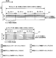
- FIG. 2 is a diagram showing an example of the frequency band aggregation processing of the present invention.
- the horizontal axis represents the frequency domain
- the vertical axis represents the time domain.
- the downlink subframe D1 includes four downlink component carriers (DL CC-1; Downlink Component Carrier-1, DL CC-2, DL CC-3, DL) having a bandwidth of 20 MHz. It is composed of DL CC-4) subframes.
- DL CC-1 Downlink Component Carrier-1, DL CC-2, DL CC-3, DL
- DL downlink component carriers
- DL CC-1 Downlink Component Carrier-1
- DL CC-2 Downlink Component Carrier-1
- DL CC-3 DL
- the region where the PHICH is arranged and the region where the PDCCH is arranged are frequency multiplexed and / or time multiplexed.
- a region where PHICH and PDCCH are frequency-multiplexed and / or time-multiplexed and a region where PDSCH is arranged are time-multiplexed.
- the uplink subframe U1 is composed of three uplink component carriers (UL-CC-1; Uplink-Component Carrier-1, UL-CC-2, UL-CC-3) having a bandwidth of 20 MHz.
- Each of the subframes of the uplink component carrier has a frequency in which a PUCCH indicated by a hatched area with a diagonally downward slanting line and a region in which a PUSCH indicated by a hatched area with a horizontal line are arranged. Is multiplexed.
- the mobile station apparatus 1 performs initial access with the base station apparatus 3 using any one set of downlink component carrier and uplink component carrier.
- the base station apparatus 3 uses the RRC signal (Radio Resource Control signal) transmitted using the PDSCH of the downlink component carrier that the mobile station device 1 has made initial access to set the downlink component carrier set for the mobile station device 1.
- RRC signal Radio Resource Control signal
- an uplink component carrier hereinafter, referred to as “configured component (carrier)”.
- the base station apparatus 3 sends an activation command (activation command) indicating a downlink component carrier to be used for downlink communication from among the set downlink component carriers, PDCCH or MAC (Medium Access Control) CE (Control Element) Notify using etc.
- the activation command is composed of a bitmap, and when the value of the bit corresponding to each downlink component carrier is “1”, this indicates that the downlink component carrier is used for downlink communication, and the bit value “0” indicates that the downlink component carrier is not used for downlink communication.
- the activation command is applied after a predetermined time after receiving the activation command (for example, after one subframe or after four subframes).
- the MAC CE is transmitted using PDSCH.
- the base station apparatus 3 When the base station apparatus 3 notifies the mobile station apparatus 1 that the downlink component carrier is used for downlink communication with an activation command, it is referred to as activating the downlink component carrier. Notifying the mobile station device 1 that the downlink component carrier is not used for downlink communication by the activation command by the base station device 3 is referred to as deactivating the downlink component carrier.
- An activated downlink component carrier is called an activated downlink component carrier (activated downlink component carrier) or configured and activated downlink component carrier (configured and activated downlink component carrier) and is deactivated
- the component carrier is referred to as a deactivated downlink component carrier (deactivated downlink component carrier) or a configured and deactivated downlink component carrier (configured and deactivated downlink component carrier).
- the mobile station device 1 may deactivate the downlink component carrier by a method different from the method of deactivating the downlink component carrier notified by the activation command that it is not used for downlink communication. For example, the mobile station device 1 may deactivate the downlink component carrier when a predetermined time has elapsed after the activation of the downlink component carrier with the activation command, or the activated downlink component carrier The downlink component carrier may be deactivated when a predetermined time has elapsed since the last reception of PDCCH or PDSCH. That is, the downlink component carrier may be deactivated based on the judgment of the mobile station device 1 itself. Note that the base station apparatus 3 may set the predetermined time and notify the mobile station apparatus 1 of information including this setting with an RRC signal.
- the mobile station device 1 does not receive the deactivated downlink component carrier signal.
- the base station apparatus 3 determines that the mobile station apparatus 1 does not receive the deactivated downlink component carrier signal. For example, the base station apparatus 3 arranges a signal (PDSCH, PDCCH, PHICH, etc.) on one or more downlink component carriers among the activated downlink component carriers in the downlink subframe, and Transmit to device 1.
- the mobile station apparatus 1 performs monitoring and reception processing only on the activated downlink component carrier signals (PDSCH, PDCCH, PHICH, etc.).
- the base station apparatus 3 moves the downlink primary component carrier (downlink primary component carrier: DL PCC) and uplink component carrier uplink primary component carrier: UL PCC) from among the configured downlink component carrier and uplink component carrier.
- Downlink primary component carrier downlink primary component carrier: DL PCC
- uplink component carrier uplink primary component carrier UL PCC
- the base station apparatus 3 cannot deactivate the downlink primary component carrier, that is, the downlink primary component carrier is always activated.
- the uplink primary component carrier is used to transmit uplink control information.
- the base station apparatus 3 allocates the PUSCH radio resource of one or more uplink component carriers among the configured uplink component carriers in the uplink subframe, and indicates the radio resource allocation to this PUSCH.
- Control information (Downlink Control Information: DCI) is transmitted on the activated PDCCH of the downlink component carrier.
- the mobile station apparatus 1 arranges a signal on the PUSCH of one or a plurality of uplink component carriers among the configured uplink component carriers in accordance with the downlink control information indicating the allocation of the radio resources of the PUSCH, and the base station apparatus 3 to send.
- the downlink control information for the PDSCH of the downlink component carrier and the PUSCH of the uplink component carrier is one of the downlink component carriers set and activated. It is transmitted to mobile station apparatus 1 using the PDCCH of the carrier.
- the PDCCH for the PDSCH of the downlink component carrier and the PDCCH for the PUSCH of the uplink component carrier may be arranged in different downlink component carriers for each subframe.
- the PDCCH for the PUU of UL CC-1 is one downlink component carrier (DL CC-1 or DL CC-1) among DL CC-1 to DL CC-4. -2, or DL CC-3 or DL CC-4).
- the downlink component carrier that can transmit the PDSCH of the downlink component carrier or the PUSCH of the uplink component carrier can be limited.
- the PDCCH for the PUSCH of UL-CC-1 may be limited to be transmitted only on one downlink component carrier among DL-CC1 and DL-CC2 for each subframe.
- the HARQ (Hybrid Automatic Repeat Repeat) reQuest (HARQ) indicator that indicates the success or failure of decoding of the PUSCH transmitted by the mobile station apparatus 1 on the uplink component carrier is transmitted on the PHICH of the downlink component carrier on which the PDCCH for this PUSCH was last transmitted.
- HARQ indicator for this PUSCH is DL CC- 1 is transmitted with PHICH.
- the base station apparatus 3 successfully decodes the PUSCH, the HARQ indicator indicates ACK (ACKnowledgement), and when the base station apparatus fails to decode the PUSCH, the HARQ indicator indicates NACK (Negative ACKnowledgement).
- FIG. 3 is a schematic diagram illustrating an example of a configuration of a downlink radio frame according to the present invention.
- FIG. 3 shows a configuration of a radio frame in the downlink component carrier.
- the horizontal axis is the time domain
- the vertical axis is the frequency domain.
- the radio frame of the downlink component carrier is composed of a plurality of downlink physical resource block (PhysicalPhysResource Block; PRB) pairs (for example, an area surrounded by a broken line in FIG. 3).
- PRB downlink physical resource block
- One downlink physical resource block pair is composed of two downlink physical resource blocks (PRB bandwidth ⁇ slot) that are continuous in the time domain.
- One downlink physical resource block (unit surrounded by a thick line in FIG. 3) is composed of 12 subcarriers (15 kHz) in the frequency domain, and 7 OFDMs (Orthogonal Frequency Frequency Division) in the time domain. Multiplexing) symbol (71 ⁇ s).
- TTI Transmit Time Interval
- a plurality of downlink physical resource blocks are arranged according to the bandwidth of the downlink component carrier.
- a unit composed of one subcarrier and one OFDM symbol is referred to as a downlink resource element.
- PDCCH Physical Downlink Control
- PHICH Physical Downlink Control
- PDSCH Physical Downlink Reference Signal
- a downlink reference signal a downlink reference signal
- PDCCH is arranged from the OFDM symbol at the head of the subframe (the area hatched with a diagonal line rising to the right in FIG. 3). Note that the number of OFDM symbols in which the PDCCH is arranged is 1 to 3, and is different for each subframe.
- the PDCCH includes downlink control information, which is information used for communication control, configured in an information format such as downlink assignment (also referred to as downlink assignment) or uplink grant (Uplink grant). A signal is placed.
- a plurality of PDCCHs are frequency-multiplexed and time-multiplexed in each downlink component carrier.
- the downlink assignment includes information regarding modulation scheme and coding for PDSCH, information indicating radio resource allocation, information regarding HARQ indicating initial transmission or retransmission, a TPC command, and the like.
- the uplink grant includes information on modulation scheme and coding for PUSCH, information indicating radio resource allocation, information on HARQ indicating initial transmission or retransmission, a TPC command, and the like.
- HARQ means that, for example, the mobile station apparatus 1 (base station apparatus 3) transmits HARQ feedback indicating success or failure of data decoding to the base station apparatus 3 (mobile station apparatus 1), and the mobile station apparatus 1 (base station apparatus).
- the base station device 3 When the device 3) cannot decode data due to an error (NACK), the base station device 3 (mobile station device 1) retransmits the signal, and the mobile station device 1 (base station device 3) has already received the signal again.
- NACK an error
- NDI New Data Indicator
- the mobile station apparatus 1 When receiving the downlink assignment or the uplink grant, the mobile station apparatus 1 stores the NDI included in the received downlink assignment or the uplink grant. At this time, if the mobile station apparatus 1 already stores the NDI, it is determined whether the NDI is toggled, and then overwritten with the new NDI.
- the mobile station apparatus 1 determines that the downlink assignment or uplink grant indicates initial transmission. When the NDI is not toggled, the mobile station apparatus 1 determines the downlink assignment or uplink. It is determined that the grant indicates retransmission.
- NDI is toggled means that the stored NDI value is different from the received NDI value. If NDI is not toggled, the stored NDI value is the same as the received NDI value. It is to be.
- the NDI included in the downlink assignment or uplink grant is toggled, and the downlink assignment or uplink grant is referred to as instructing initial transmission, and the NDI is not toggled. It is said that the downlink assignment or the uplink grant is instructing retransmission.
- the base station apparatus 3 adds, to the downlink control information, a sequence obtained by scrambling the cyclic redundancy check (Cyclic Redundancy Check: CRC) code generated based on the downlink control information with an RNTI (Radio Network Temporary Identifier). .
- CRC Cyclic Redundancy Check
- RNTI Radio Network Temporary Identifier
- the cyclic redundancy check code is scrambled by the C-RNTI (Cell-Radio Network Temporary Identity) assigned by the mobile station apparatus 1 from the base station apparatus 3, the downlink control information is addressed to the mobile station apparatus 1 It is determined that the radio resource is indicated.
- C-RNTI Cell-Radio Network Temporary Identity
- the addition of a cyclic redundancy check code scrambled with RNTI to downlink control information is simply expressed as RNTI included in downlink control information or RNTI included in PDCCH.
- the mobile station apparatus 1 decodes the PDCCH, descrambles the sequence corresponding to the cyclic redundancy check code scrambled by the RNTI with the RNTI stored by the mobile station apparatus 1, and makes an error based on the descrambled cyclic redundancy check code.
- it is detected that there is no PDCCH it is determined that acquisition of the PDCCH is successful. This process is called blind decoding.
- PHICH will be described.
- PHICH and PDCCH are frequency-multiplexed within the same OFDM symbol (the area hatched with a mesh line in FIG. 3).
- the PHICH may be arranged only in the first OFDM symbol of the subframe, or may be arranged dispersed in a plurality of OFDM symbols.
- a HARQ indicator indicating success / failure of PUSCH decoding (ACK / NACK) is arranged.
- a plurality of PHICHs are frequency-multiplexed and code-multiplexed in each downlink component carrier.
- the HARQ indicator indicating the success or failure of decoding of the PUSCH transmitted by the mobile station apparatus 1 using the uplink component carrier is transmitted using the PHICH of the downlink component carrier that is the last transmitted uplink grant for this PUSCH. Also, in which PHICH in the downlink component carrier the HARQ indicator for the PUSCH is arranged is the physical resource block with the smallest number (of the lowest frequency region) among the physical resource blocks allocated to this PUSCH. It is determined from the number and information related to the cyclic shift of the uplink reference signal time-multiplexed with the PUSCH, which is included in the uplink grant.
- the mobile station apparatus 1 receives HARQ feedback for this PUSCH in a PHICH of a downlink subframe after a predetermined time (for example, 4 ms, 4 subframes, 4 TTIs) after transmitting the PUSCH.
- a predetermined time for example, 4 ms, 4 subframes, 4 TTIs
- code multiplexing is used, and a plurality of different codes are used.
- a plurality of different codes are generated by periodically shifting (referred to as cyclic shift) a predetermined basic sequence, and different codes are generated by cyclic shifts of different shift amounts.
- the PDSCH is arranged in an OFDM symbol other than the OFDM symbol in which the PDCCH and / or PHICH of the subframe is arranged (in FIG. 3, a region not hatched).
- a signal of downlink data (or “transport block”) is arranged.
- PDSCH radio resources are allocated using downlink assignment.
- the PDSCH radio resources are arranged in the same downlink subframe as the PDCCH including the downlink assignment used for the PDSCH assignment in the time domain, and the downlink used for the PDSCH assignment in the frequency domain. It is arranged on the same downlink component carrier as the PDCCH including the link assignment or on a different downlink component carrier.
- the downlink assignment includes information (hereinafter referred to as “downlink carrier indicator”) indicating which downlink component carrier the PDSCH is for which downlink component carrier.
- downlink carrier indicator information indicating which downlink component carrier the PDSCH is for which downlink component carrier.
- the downlink assignment not including the downlink carrier indicator and the PDSCH corresponding to the downlink assignment are transmitted on the same downlink component carrier.
- a plurality of PDSCHs are frequency-multiplexed and spatially multiplexed in each downlink component carrier.
- the downlink reference signal is not shown in FIG. 3 for simplicity of explanation, but the downlink reference signal is distributed and arranged in the frequency domain and the time domain.
- FIG. 4 is a schematic diagram showing an example of the configuration of an uplink radio frame according to the present invention.
- FIG. 4 shows a configuration of a radio frame in the uplink component carrier.
- the horizontal axis is the time domain
- the vertical axis is the frequency domain.
- the uplink radio frame is composed of a plurality of uplink physical resource block pairs (for example, an area surrounded by a broken line in FIG. 4).
- One uplink physical resource block pair is composed of two uplink physical resource blocks (PRB bandwidth ⁇ slot) that are continuous in the time domain.
- One uplink physical resource block (unit surrounded by a thick line in FIG. 4) is composed of 12 subcarriers (15 kHz) in the frequency domain, and 7 SC-FDMA symbols ( 71 ⁇ s).
- a slot (0.5 ms) composed of seven SC-FDMA (Single-Carrier Frequency Division Multiple Access) symbols (71 ⁇ s), a subframe (1 ms) composed of two slots, 10
- a radio frame (10 ms) composed of subframes. 1 ms which is the same time interval as the subframe is also referred to as a transmission time interval (Transmit Time Interval: TTI).
- TTI Transmit Time Interval
- a plurality of uplink physical resource blocks are arranged according to the bandwidth of the uplink component carrier.
- a unit composed of one subcarrier and one SC-FDMA symbol is referred to as an uplink resource element.
- the channels allocated in the uplink radio frame will be described.
- a PUCCH In each uplink subframe, for example, a PUCCH, a PUSCH, and an uplink reference signal are allocated.
- PUCCH will be described.
- the PUCCH is allocated to uplink physical resource block pairs (regions hatched with diagonal lines rising to the right) at both ends of the band of the uplink component carrier.
- the PUCCH includes communication quality control such as channel quality information (Channel Quality Information) indicating downlink channel quality, a scheduling request (Scheduling Request: SR) indicating a request for allocation of uplink radio resources, and ACK / NACK for the PDSCH.
- Uplink control information Uplink Control Information (Uplink Control Information: UCI) signal, which is information used for the transmission, is arranged.
- a plurality of PUCCHs are frequency-multiplexed and code-multiplexed in each uplink component carrier.
- the PUSCH is assigned to an uplink physical resource block pair (an area that is not hatched) other than the uplink physical resource block in which the PUCCH is arranged.
- uplink control information and uplink data (transport block; Transport Block) signals that are information other than the uplink control information are arranged.
- PUSCH radio resources are allocated using an uplink grant, and after a predetermined time from a downlink subframe in which a PDCCH including the uplink grant is arranged (for example, 4 ms later, 4 subframes later, 4 TTI later) Are arranged in uplink subframes.
- the uplink grant includes information (hereinafter referred to as “uplink carrier indicator”) indicating which uplink component carrier the PUSCH is for the uplink component carrier. Further, when the uplink grant does not include an uplink carrier indicator, the uplink grant that does not include the uplink carrier indicator is a downlink component that is associated in advance with the uplink component carrier to which the uplink grant corresponds. Sent on carrier. In each subframe, a plurality of PUSCHs are frequency-multiplexed and spatially multiplexed in each uplink component carrier.
- the uplink reference signal is time-multiplexed with PUCCH and PUSCH, but detailed description is omitted for the sake of simplicity.
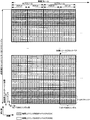
- FIG. 5 is a schematic diagram for explaining the uplink HARQ process of the present invention.
- the horizontal axis is the time domain
- a square hatched with a mesh-like line indicates PHICH
- a square hatched with an upward slanting diagonal line indicates PDCCH (uplink grant)
- a horizontal line hatches The marked squares indicate PUSCH, and the numbers given to PHICH, PDCCH, and PUSCH indicate the number of the HARQ process to which each channel corresponds.
- multiple (eight) HARQ processes operate independently and simultaneously for each uplink component carrier.
- the HARQ process number corresponding to the PUSCH is associated with the uplink subframe number. For example, the remainder of dividing the subframe number by the number of HARQ processes operating simultaneously in the uplink component carrier is set as the HARQ process number in the uplink component carrier corresponding to the subframe.
- the number of the HARQ process to which PHICH and PDCCH (uplink grant) correspond is associated with the number of the downlink subframe. In the uplink and downlink, the corresponding HARQ process number is shifted by four.
- FIG. 5 shows only the PUSCH of one uplink component carrier.
- Each HARQ process is associated with one HARQ buffer.
- the mobile station apparatus 1 stores the uplink data (transport block) transmitted on the PUSCH in the HARQ buffer of the HARQ process corresponding to the PUSCH, stores the uplink grant received last on the corresponding PDCCH, and HARQ. ACK or NACK set as feedback is stored.
- the base station apparatus 3 stores the uplink data received and decoded on the PUSCH in the HARQ buffer of the HARQ process corresponding to the PUSCH, and the uplink grant transmitted last on the corresponding PDCCH.
- each HARQ process has one It is necessary to be associated with the same number of HARQ buffers as the number of uplink data (transport blocks) transmitted on the PUSCH.
- a PDCCH (uplink grant) for a HARQ process of a certain uplink component carrier may be transmitted using a different downlink component carrier for each HARQ process timing, or a downlink component carrier corresponding to each uplink component carrier. May be sent only.
- the PHICH for the HARQ process of a certain uplink component carrier is transmitted on the downlink component carrier to which the PDCCH (uplink grant) related to the HARQ process is last transmitted.
- the mobile station apparatus 1 receives a PDCCH (uplink grant) instructing initial transmission related to the HARQ process No. 0 in the nth downlink subframe, and the n + 4th uplink subframe. Then, the PUSCH for the HARQ process number 0 is initially transmitted according to this PDCCH (uplink grant).
- the mobile station apparatus 1 receives the PHICH and the PDCCH (uplink grant) related to the HARQ process # 0 in the (n + 8) th downlink subframe, and receives this PHICH or PDCCH (uplink grant) in the (n + 12) th uplink subframe.
- initial transmission or retransmission of PUSCH related to the HARQ process of No. 0 is performed.
- the downlink subframe and the uplink subframe corresponding to the same HARQ process are shifted by 4 ms (4 subframes, 4 TTIs).
- PHICH, PDCCH (uplink grant) and PUSCH for the same HARQ process are transmitted at intervals of 8 ms (8 subframes, 8 TTI).
- the mobile station apparatus 1 first sets ACK or NACK indicated by the HARQ indicator received by PHICH as HARQ feedback.
- the mobile station apparatus 1 receives the uplink grant instructing the initial transmission of the PUSCH on the PDCCH, the mobile station apparatus 1 determines new uplink data to be transmitted on the PUSCH without depending on the ACK or NACK set as the HARQ feedback.
- the uplink data is stored in the HARQ buffer, the received uplink grant is stored, PUSCH is initially transmitted according to the stored uplink grant, and NACK is set as HARQ feedback.
- the mobile station apparatus 1 When the mobile station apparatus 1 receives the uplink grant instructing the PUSCH retransmission on the PDCCH, the mobile station apparatus 1 does not depend on the ACK or NACK set as the HARQ feedback and receives the stored uplink grant. Overwrite the link grant, retransmit the uplink data stored in the HARQ buffer according to the overwritten uplink grant on the PUSCH, and set NACK as HARQ feedback.
- the HARQ buffer is empty, the mobile station device 1 determines the uplink data to be transmitted on the PUSCH without depending on whether the uplink grant instructs initial transmission or re-transmission. Uplink data is stored in the HARQ buffer, the received uplink grant is stored, PUSCH is initially transmitted according to the stored uplink grant, and NACK is set as HARQ feedback.
- the mobile station apparatus 1 When the mobile station apparatus 1 does not receive the uplink grant for the PUSCH and NACK is set as the HARQ feedback, the mobile station apparatus 1 retransmits the uplink data stored in the HARQ buffer on the PUSCH according to the stored uplink grant. Send.
- the mobile station apparatus 1 does not receive the uplink grant for the PUSCH and ACK is set as the HARQ feedback, the mobile station apparatus 1 does not transmit the PUSCH, and is stored in the HARQ buffer managed by the HARQ process. Retain data.
- the mobile station apparatus 1 When the mobile station apparatus 1 receives an uplink grant for the PUSCH of the UL CC-1 in the n th subframe of the DL CC-1 in FIG. 5, the n + 4th subframe of the UL CC-1 according to the received uplink grant. Transmits PUSCH and sets NACK as HARQ feedback.
- DL CC-1 is deactivated before the n + 8th subframe in which the mobile station device 1 receives the PHICH for this PUSCH in DL CC-1, the mobile station device 1 performs the DL in the n + 8th subframe.
- CC-1 cannot receive PHICH.
- the mobile station apparatus 1 is an uplink subframe corresponding to the 0th HARQ process ((n + 4 + 8 ⁇ i) th subframe: i is an integer), and n
- the PUSCH retransmission is continued according to the uplink grant received in the subframe of the first DL CC-1.
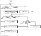
- FIG. 6 is a flowchart showing an example of the operation of the mobile station apparatus 1 of the present invention.
- the mobile station apparatus 1 performs the process of FIG. 6 for each HARQ process.
- the mobile station apparatus 1 activates the downlink component carrier that receives the PHICH for the HARQ process (that is, the downlink component carrier that lastly received the uplink grant for the HARQ process). It is determined whether or not (step S100).
- the mobile station apparatus 1 determines whether or not an uplink grant addressed to itself is detected (step S103). When determining that the uplink grant has been detected, the mobile station device 1 stores the detected uplink grant, sets NACK as HARQ feedback (step S104), and performs initial transmission of PUSCH according to the stored uplink grant or Re-transmission is performed (step S106).
- the mobile station device 1 determines whether ACK or NACK is set as HARQ feedback (step S105). When determining that NACK is set as HARQ feedback in step S105, the mobile station apparatus 1 performs PUSCH retransmission according to the stored uplink grant (step S106). If it is determined in step S105 that ACK is set as HARQ feedback, the mobile station device 1 does not transmit the PUSCH and retains the content of the HARQ buffer corresponding to the HARQ process (step S107).
- Step S106 and Step S107 the mobile station apparatus 1 returns to Step S100 in the next downlink subframe corresponding to this HARQ process (Step S108), and the downlink component carrier that receives the PHICH for the HARQ process is activated. It is determined whether or not it has been done.
- Step S100 when it is determined that the downlink component carrier that receives PHICH is not activated, that is, has been deactivated, the mobile station device 1 does not receive PHICH and sets ACK as HARQ feedback ( Step S102). If the downlink component carrier capable of transmitting the uplink grant for the HARQ process of the uplink component carrier is not among the activated downlink component carriers, the mobile station apparatus 1 performs ACK in step S102. In step S103, it is determined that no uplink grant has been detected. In step S105, it is determined that ACK has been set in HARQ feedback. In step S107, PUSCH is not transmitted, and the HARQ process is supported. The contents of the HARQ buffer to be held are held.
- the base station apparatus 3 transmits an uplink grant.
- the mobile station apparatus 1 determines that the uplink grant is detected in step S103 after setting the ACK in step S102 by transmitting the uplink grant on the activated downlink component carrier that can be activated.
- PUSCH can be initially transmitted or retransmitted according to the received and detected uplink grant.
- ACK is set as the HARQ feedback.
- the mobile station apparatus 1 may not receive the PHICH corresponding to the HARQ process in step S101. If the uplink grant instructing retransmission is received after holding the contents of the HARQ buffer in step S107, the contents of the HARQ buffer can be retransmitted on the PUSCH.
- the base station device 3 transmits an uplink grant using an activated downlink component carrier, deactivates the downlink component carrier used for transmission of the uplink grant, and uses the deactivated downlink component carrier.
- the mobile station apparatus 1 can be instructed to re-activate and retransmit the PUSCH transmitted in the previously activated state.
- FIG. 7 is a schematic block diagram showing the configuration of the mobile station apparatus 1 of the present invention.
- the mobile station apparatus 1 includes an upper layer processing unit 101, a control unit 103, a receiving unit 105, a transmitting unit 107, and a transmission / reception antenna 109.
- the upper layer processing unit 101 includes a radio resource control unit 1011, a HARQ control unit 1013, and a HARQ storage unit 1015.
- the reception unit 105 includes a decoding unit 1051, a demodulation unit 1053, a demultiplexing unit 1055, a radio reception unit 1057, and a channel measurement unit 1059.
- the transmission unit 107 includes an encoding unit 1071, a modulation unit 1073, a multiplexing unit 1075, a radio transmission unit 1077, and an uplink reference signal generation unit 1079.
- the upper layer processing unit 101 outputs the uplink data, the RRC signal, and the MAC-CE generated by the user operation or the like to the transmission unit 1007.
- the upper layer processing unit 101 includes a medium access control (MAC: Medium Access Control) layer, a packet data integration protocol (Packet Data Convergence Protocol: PDCP) layer, a radio link control (Radio Link Control: RLC) layer, and radio resource control. Process the (Radio Resource Control: RRC) layer.
- MAC Medium Access Control
- PDCP Packet Data Convergence Protocol
- RLC Radio Link Control
- RRC Radio Resource Control
- upper layer processing section 101 generates control information for controlling receiving section 105 and transmitting section 107 based on downlink control information received by PDCCH, and outputs the control information to control section 103.
- the radio resource control unit 1011 included in the higher layer processing unit 101 manages various setting information of the own device. For example, the radio resource control unit 1011 manages RNTI such as C-RNTI. Also, the radio resource control
- the radio resource control unit 1011 manages the downlink component carrier and the uplink component carrier set by the RRC signal notified from the base station apparatus 3, and the downlink component carrier activated or deactivated by an activation command or the like. Do.
- the radio resource control unit 1011 manages the downlink component carrier in which the downlink assignment for the configured downlink component carrier and the uplink grant for the configured uplink component carrier are arranged.
- the HARQ control unit 1013 included in the higher layer processing unit 101 manages an uplink HARQ process.
- the HARQ storage unit 1015 included in the higher layer processing unit 101 includes a HARQ buffer associated with each uplink HARQ process managed by the HARQ control unit 1013.
- the HARQ storage unit 1015 stores uplink grants and HARQ feedback (ACK or NACK) related to each HARQ process.
- ACK or NACK HARQ feedback
- the HARQ control unit 1013 performs the following operation for each HARQ process.
- the HARQ control unit 1013 inputs uplink data (transport block) transmitted on the PUSCH to the HARQ buffer, and receives the ACK or NACK indicated by the HARQ indicator received from the PHICH input from the reception unit 105 and the PDCCH.
- the uplink grant is stored in the HARQ storage unit 1015.
- the HARQ control unit 1013 performs HARQ control according to the flowchart of FIG. 6 based on the ACK or NACK stored in the HARQ storage unit 1015 and the uplink grant.
- the HARQ control unit 1013 associates the HARQ process with the uplink component carrier and subframe number (timing) in which the PUSCH is transmitted.
- HARQ control section 1013 assigns PUSCH physical resource blocks among a plurality of PHICHs in the downlink component carrier in which the uplink grant was last received, and cyclic shift of the uplink reference signal that is time-multiplexed with PUSCH.
- the PHICH corresponding to this HARQ process is determined from the information included in the uplink grant.
- the HARQ control unit 1013 determines the HARQ process corresponding to the received uplink grant from the uplink carrier indicator included in the uplink grant and the number (timing) of the subframe in which the uplink grant is received. When the uplink grant does not include the uplink carrier indicator, the HARQ control unit 1013 determines that the received uplink grant is based on the downlink component carrier and the subframe number (timing) from which the uplink grant is received. Determine the corresponding HARQ process.
- the control unit 103 generates a control signal for controlling the receiving unit 105 and the transmitting unit 107 based on the control information from the higher layer processing unit 101.
- Control unit 103 outputs the generated control signal to receiving unit 105 and transmitting unit 107 to control receiving unit 105 and transmitting unit 107.
- the receiving unit 105 separates, demodulates, and decodes the received signal received from the base station apparatus 3 via the transmission / reception antenna 109 according to the control signal input from the control unit 103, and sends the decoded information to the upper layer processing unit 101. Output.
- the radio reception unit 1057 converts the downlink signal received via the transmission / reception antenna 109 into an intermediate frequency (down-conversion: down covert), removes unnecessary frequency components, and maintains the signal level appropriately. Then, the amplification level is controlled, quadrature demodulation is performed based on the in-phase component and the quadrature component of the received signal, and the quadrature demodulated analog signal is converted into a digital signal.
- the radio reception unit 1057 removes a portion corresponding to a guard interval (Guard Interval: GI) from the converted digital signal, performs a fast Fourier transform (FFT Fourier Transform: FFT) on the signal from which the guard interval is removed, Extract the region signal.
- GI Guard Interval
- FFT fast Fourier transform
- the demultiplexing unit 1055 separates the extracted signals into PHICH, PDCCH, PDSCH, and downlink reference signals. This separation is performed based on radio resource allocation information notified by downlink assignment. Further, demultiplexing section 1055 compensates the propagation path of PHICH, PDCCH, and PDSCH from the estimated propagation path value input from channel measurement section 1059. Also, the demultiplexing unit 1055 outputs the demultiplexed downlink reference signal to the channel measurement unit 1059.
- the demodulator 1053 demodulates the PHICH using a BPSK (Binary Phase Shift Keying) modulation method and outputs the demodulated signal to the decoding unit 1051.
- Decoding section 1051 decodes the PHICH addressed to the own apparatus, and outputs the decoded HARQ indicator to higher layer processing section 101.
- Demodulation section 1053 demodulates the QPSK modulation scheme for PDCCH and outputs the result to decoding section 1051.
- Decoding section 1051 attempts blind decoding of PDCCH, and when blind decoding is successful, decodes downlink control information and outputs RNTI included in downlink control information to higher layer processing section 101.
- the demodulation unit 1053 demodulates the modulation scheme notified by downlink assignment such as QPSK (Quadrature Phase Shift Keying), 16QAM (Quadrature Amplitude Modulation), 64QAM, etc., and outputs the result to the decoding unit 1051.
- Decoding section 1051 performs decoding based on the information regarding the coding rate notified by the downlink control information, and outputs the decoded downlink data (transport block) to higher layer processing section 101.
- the channel measurement unit 1059 measures the downlink path loss and channel state from the downlink reference signal input from the demultiplexing unit 1055, and outputs the measured path loss and channel state to the upper layer processing unit 101. Also, channel measurement section 1059 calculates an estimated value of the downlink propagation path from the downlink reference signal, and outputs it to demultiplexing section 1055.
- the transmission unit 107 generates an uplink reference signal according to the control signal input from the control unit 103, encodes and modulates the uplink data (transport block) input from the higher layer processing unit 101, PUCCH, The PUSCH and the generated uplink reference signal are multiplexed and transmitted to the base station apparatus 3 via the transmission / reception antenna 109.
- the coding unit 1071 performs coding such as convolution coding and block coding on the uplink control information input from the higher layer processing unit 101, and relates to the coding rate in which the uplink data is notified by the uplink grant. Turbo coding is performed based on the information.
- the modulation unit 1073 modulates the coded bits input from the coding unit 1071 using a modulation method notified by downlink control information such as BPSK, QPSK, 16QAM, 64QAM, or a modulation method predetermined for each channel. .
- the uplink reference signal generation unit 1079 is a physical cell identifier for identifying the base station device 3 (referred to as physical cell ⁇ ⁇ identity: ⁇ ⁇ ⁇ PCI, Cell ⁇ ID, etc.), a bandwidth for arranging the uplink reference signal, and an uplink grant. Based on the notified cyclic shift or the like, the base station apparatus 3 obtains a known sequence that is obtained by a predetermined rule.
- the multiplexing unit 1075 rearranges the PUSCH modulation symbols in parallel in accordance with the control signal input from the control unit 103, and then performs discrete Fourier transform (Discrete Fourier Transform: DFT) to generate the PUCCH and PUSCH signals and the generated uplink reference Multiplex the signal.
- DFT discrete Fourier Transform
- Radio transmitter 1077 performs inverse fast Fourier transform (IFFT) on the multiplexed signal, performs SC-FDMA modulation, and adds a guard interval to the SC-FDMA-modulated SC-FDMA symbol.
- IFFT inverse fast Fourier transform
- Generating a baseband digital signal converting the baseband digital signal to an analog signal, generating an in-phase component and a quadrature component of an intermediate frequency from the analog signal, removing an extra frequency component for the intermediate frequency band,
- the intermediate frequency signal is converted to a high frequency signal (up-conversion: up convert), an extra frequency component is removed, the power is amplified, and output to the transmission / reception antenna 109 for transmission.
- FIG. 8 is a schematic block diagram showing the configuration of the base station apparatus 3 of the present invention.
- the base station apparatus 3 includes an upper layer processing unit 301, a control unit 303, a reception unit 305, a transmission unit 307, and a transmission / reception antenna 309.
- the upper layer processing unit 301 includes a radio resource control unit 3011, a HARQ control unit 3013, and a HARQ storage unit 3015.
- the reception unit 305 includes a decoding unit 3051, a demodulation unit 3053, a demultiplexing unit 3055, a wireless reception unit 3057, and a channel measurement unit 3059.
- the transmission unit 307 includes an encoding unit 3071, a modulation unit 3073, a multiplexing unit 3075, a radio transmission unit 3077, and a downlink reference signal generation unit 3079.
- the upper layer processing unit 301 includes a medium access control (MAC: Medium Access Control) layer, a packet data integration protocol (Packet Data Convergence Protocol: PDCP) layer, a radio link control (Radio Link Control: RLC) layer, a radio resource control (Radio). Resource (Control: RRC) layer processing. Further, upper layer processing section 301 generates control information for controlling receiving section 305 and transmitting section 307 and outputs the control information to control section 303.
- the radio resource control unit 3011 included in the upper layer processing unit 301 generates downlink data (transport block), RRC signal, MAC CE arranged in the downlink PDSCH, or acquires from the upper node, and transmits the transmission unit 307. Output to. Further, the radio resource control unit 3011 manages various setting information of each mobile station apparatus 1. For example, the radio resource control unit 3011 performs RNTI management such as assigning C-RNTI to the mobile station apparatus 1.
- RNTI management such as assigning C-RNTI to the mobile station apparatus 1.
- the radio resource control unit 3011 manages the downlink component carrier and the uplink component carrier set for each mobile station apparatus 1 and the activated or deactivated downlink component carrier.
- the radio resource control unit 3011 sets a downlink component carrier and an uplink component carrier to be used for communication to each mobile station apparatus 1 and transmits via the control unit 303 so as to notify information related to this setting with an RRC signal.
- the unit 307 is controlled.
- the radio resource control unit 3011 sets the downlink component carrier used for communication and the downlink component carrier on which the PDCCH for the uplink component carrier is arranged for each mobile station apparatus 1, and notifies information related to this setting using an RRC signal.
- the transmission unit 307 is controlled via the control unit 303.
- the radio resource control unit 3011 controls the transmission unit 307 via the control unit 303 so that each mobile station apparatus 1 is notified of the activation command by PDCCH or MAC / CE.
- the HARQ control unit 3013 provided in the higher layer processing unit 301 manages the uplink HARQ process of each mobile station apparatus 1.
- the HARQ storage unit 3015 provided in the higher layer processing unit 301 includes a plurality of HARQ buffers corresponding to each uplink HARQ process managed by the HARQ control unit 3013.
- the downlink HARQ process is not related to the present invention, and thus the description thereof is omitted.
- the uplink data (transport block) received by the PUSCH input from the HARQ control unit 3013 and the reception unit 305 is input to the HARQ buffer, and an error detection code (cyclic redundancy check code) added to the uplink data is used. Then, it is determined whether or not the uplink data has been successfully decoded.
- the HARQ control unit 3013 generates a HARQ indicator indicating ACK when determining that the decoding of uplink data is successful, and generates a HARQ indicator indicating NACK when determining that the decoding of the uplink data has failed. And output to the transmission unit 307.
- the HARQ control unit 3013 determines that the decoding of the uplink data has failed, the HARQ control unit 3013 changes the information on the radio resource allocation, the modulation scheme, and the coding rate, and sets the uplink grant that instructs retransmission including the changed information.
- the transmission unit 307 may be controlled via the control unit 303 so as to transmit.
- the HARQ control unit 3013 When the uplink data retransmitted in the mobile station apparatus 1 is input from the reception unit 305, the HARQ control unit 3013 combines the uplink data already stored in the HARQ buffer and the retransmitted uplink data. Then, it is determined whether or not the uplink data has been successfully decoded. The HARQ control unit 3013 associates the uplink component carrier and subframe number (timing) with which the mobile station apparatus 1 transmits the PUSCH with the HARQ process number.
- the HARQ control unit 3013 allocates PUSCH physical resource blocks among a plurality of PHICHs in a downlink component carrier in which an uplink grant is last transmitted for a certain HARQ process, and an uplink that is time-multiplexed with the PUSCH.
- a PHICH used to transmit ACK / NACK corresponding to this HARQ process is determined from information included in the uplink grant related to the cyclic shift of the reference signal.
- the control unit 303 generates a control signal for controlling the reception unit 305 and the transmission unit 307 based on the control information from the higher layer processing unit 301.
- the control unit 303 outputs the generated control signal to the reception unit 305 and the transmission unit 307 and controls the reception unit 305 and the transmission unit 307.
- the receiving unit 305 separates, demodulates and decodes the received signal received from the mobile station apparatus 1 via the transmission / reception antenna 309 according to the control signal input from the control unit 303, and outputs the decoded information to the higher layer processing unit 301.
- the radio reception unit 3057 converts the uplink signal received via the transmission / reception antenna 309 to an intermediate frequency (down-conversion: down covert), removes unnecessary frequency components, and maintains the signal level appropriately. Then, the amplification level is controlled, quadrature demodulation is performed based on the in-phase component and the quadrature component of the received signal, and the quadrature demodulated analog signal is converted into a digital signal.
- the wireless reception unit 3057 removes a portion corresponding to a guard interval (Guard Interval: GI) from the converted digital signal.
- the radio reception unit 3057 performs fast Fourier transform (FFT Fourier Transform: ⁇ FFT) on the signal from which the guard interval is removed, extracts a frequency domain signal, and outputs the signal to the demultiplexing unit 3055.
- FFT Fourier Transform FFT Fourier Transform: ⁇ FFT
- the demultiplexing unit 3055 demultiplexes the signal input from the radio receiving unit 3057 into signals such as PUCCH, PUSCH, and uplink reference signal. This separation is performed based on radio resource allocation information included in the uplink grant that is determined in advance by the radio resource control unit 3011 by the base station device 3 and notified to each mobile station device 1. In addition, demultiplexing section 3055 compensates for the propagation paths of PUCCH and PUSCH from the propagation path estimation value input from channel measurement section 3059. Further, the demultiplexing unit 3055 outputs the separated uplink reference signal to the channel measurement unit 3059.
- the demodulator 3053 performs inverse discrete Fourier transform (Inverse Discrete Fourier Transform: IDFT) on the PUSCH, acquires modulation symbols, and performs BPSK (Binary Shift Keying), QPSK, 16QAM, and PUCCH and PUSCH modulation symbols, respectively.
- IDFT inverse discrete Fourier transform
- BPSK Binary Shift Keying
- QPSK Quadrature Discrete Fourier Transform
- 16QAM 16QAM
- PUCCH and PUSCH modulation symbols respectively.
- the received signal is demodulated using a predetermined modulation scheme such as 64QAM, or a modulation scheme that the own device has previously notified to each mobile station device 1 using an uplink grant.
- Decoding section 3051 encodes the demodulated PUCCH and PUSCH encoded bits in a predetermined encoding scheme, or a coding rate at which the device itself has previously notified mobile station device 1 with an uplink grant. And the decoded uplink data and the uplink control information are output to the higher layer processing unit 301.
- decoding section 3051 performs decoding using the encoded bits held in the HARQ buffer input from higher layer processing section 301 and the received encoded bits.
- Channel measurement section 3059 measures an estimated value of the propagation path, channel quality, and the like from the uplink reference signal input from demultiplexing section 3055 and outputs the result to demultiplexing section 3055 and higher layer processing section 301.
- the transmission unit 307 generates a downlink reference signal according to the control signal input from the control unit 303, encodes and modulates the HARQ indicator, downlink control information, and downlink data input from the higher layer processing unit 301. Then, the PHICH, PDCCH, PDSCH, and downlink reference signal are multiplexed, and the signal is transmitted to the mobile station device 1 via the transmission / reception antenna 309.
- the encoding unit 3071 is a predetermined encoding method such as block encoding, convolutional encoding, turbo encoding, and the like for the HARQ indicator, downlink control information, and downlink data input from the higher layer processing unit 301 Or is encoded using the encoding method determined by the radio resource control unit 3011.
- the modulation unit 3073 modulates the coded bits input from the coding unit 3071 with a modulation scheme determined in advance by the radio resource control unit 3011 such as BPSK, QPSK, 16QAM, and 64QAM.
- the downlink reference signal generation unit 3079 is obtained according to a predetermined rule based on a physical cell identifier (PCI) for identifying the base station device 3, and the mobile station device 1 converts the known sequence into the downlink reference signal.
- PCI physical cell identifier
- Generate as The multiplexing unit 3075 multiplexes each modulated channel and the generated downlink reference signal.
- the wireless transmission unit 3077 performs inverse fast Fourier transform (Inverse Fast Fourier Transform: IFFT) on the multiplexed modulation symbols, modulates the OFDM scheme, adds a guard interval to the OFDM symbol that has been OFDM-modulated, and Generate digital signal, convert baseband digital signal to analog signal, generate in-phase and quadrature components of intermediate frequency from analog signal, remove excess frequency components for intermediate frequency band, convert intermediate frequency signal The signal is converted into a high-frequency signal (up-conversion: up convert), the excess frequency component is removed, the power is amplified, and output to the transmission / reception antenna 309 for transmission.
- IFFT inverse fast Fourier transform
- the uplink transmitted from the mobile station apparatus 1 to the base station apparatus 3 When the downlink component carrier that receives the PHICH in which the HARQ indicator for the link data (transport block) is arranged is deactivated, the mobile station apparatus 1 does not receive the HARQ indicator in the PHICH and does not receive the corresponding HARQ.
- ACK is set as HARQ feedback in the process, and base station apparatus 3 determines that mobile station apparatus 1 has not received the HARQ indicator arranged in PHICH and sets ACK as HARQ feedback in the corresponding HARQ process.
- the present invention can obtain the same effect even when the downlink component carrier that receives PHICH is excluded from the setting of the downlink component carrier used for communication using the RRC signal. That is, when the downlink component carrier from which PHICH is received is excluded from the downlink component carriers used for communication, the mobile station apparatus 1 sets ACK to the corresponding HARQ process.
- the mobile station apparatus 1 when the downlink component carrier is deactivated at the timing when the mobile station apparatus 1 receives PHICH in steps S100 and S102 of FIG. 6, the mobile station apparatus 1 sets ACK.
- the mobile station apparatus 1 transmits the PUSCH in S106, if it is known that the downlink component carrier that receives the PHICH is deactivated before receiving the PHICH for the PUSCH, the mobile station apparatus 1 moves after the step S106.
- the station apparatus 1 may set ACK.
- the mobile station apparatus 1 leaves the control of the base station apparatus 3 and avoids unnecessary retransmission of the PUSCH. Can be efficiently controlled.
- the RRC signal is used to set the downlink component carrier in which the PHICH for a certain uplink component carrier is not the downlink component carrier in which the uplink grant for the uplink component carrier is arranged. It may be applied to That is, when the downlink component carrier from which the PHICH is received is excluded from the downlink component carriers in which the uplink grant is arranged, the mobile station apparatus 1 sets ACK to the corresponding HARQ process.
- the mobile station apparatus 1 uses the uplink grant for UL CC-1 and The PHICH is received by DL CC-1.
- the base station apparatus 3 resets the downlink component carrier for transmitting the uplink grant for UL CC-1 to DL CC-2, and the mobile station device
- the mobile station apparatus 1 receives the PHICH for the UL-CC-1 in the DL-CC-1 and monitors the uplink grant for the UL-CC-1 in the DL-CC-2.
- the load of the reception process of the mobile station device 1 increases.
- the base station device 3 transmits the downlink component carrier that transmits the uplink grant for the UL CC-1 to the DL CC.
- -2 is reset, and when the mobile station apparatus 1 applies this setting, the mobile station apparatus 1 sets ACK in the HARQ process of UL CC-1 and performs the reception processing of the PHICH of DL CC-1. Therefore, since only the uplink grant of DL CC-2 is monitored, the load of the reception process of the mobile station apparatus 1 can be reduced.
- the mobile station device 1 when all downlink component carriers in which PHICH (HARQ indicator) and PDCCH (uplink grant) for the uplink component carrier are arranged are deactivated, the mobile station device 1
- the base station apparatus 3 erases (flashes) the contents of all HARQ buffers related to the uplink component carrier, and the base station apparatus 3 causes the mobile station apparatus 1 to perform PHICH (HARQ indicator) and PDCCH (uplink grant) for the uplink component carrier.
- the mobile station apparatus 1 Is deactivated, erases (flashes) the contents of all HARQ buffers related to the uplink component carrier. It is determined that that.
- the downlink component carrier with which the uplink grant with respect to a certain uplink component carrier is limited to one the downlink component carrier with which the HARQ indicator with respect to an uplink component carrier is arrange
- positioned was deactivated
- the contents of all HARQ buffers related to the uplink component carrier can be expressed as being erased (flushed).
- the mobile station apparatus 1 when the uplink grant for UL CC-1 is set only in DL CC-1, the mobile station apparatus 1 is UL CC when DL CC-1 is deactivated. -Erase the contents of all HARQ buffers associated with -1.
- the uplink grant for UL CC-1 when it is set that the uplink grant for UL CC-1 is arranged in DL CC-1, DL CC-2, and DL CC-3 for mobile station apparatus 1, The device 1 erases the contents of all the HARQ buffers related to the UL CC-1 when the DL CC-1, DL CC-2, and DL CC-3 are all deactivated.
- the mobile station apparatus 1 deletes the content of the HARQ buffer related to the HARQ process that cannot receive the corresponding PHICH (HARQ indicator) and PDCCH (uplink grant), thereby enabling HARQ feedback of the HARQ process. Even if NACK is set, PUSCH is not retransmitted.
- PHICH HARQ indicator
- PDCCH uplink grant
- the PUSCH transmission is determined in the HARQ process, but the PUSCH transmission is still performed. If not (when there is a pending PUSCH transmission), the content of the HARQ buffer may be erased after transmitting this PUSCH.
- the mobile station apparatus 1 receives the uplink grant from the time when the uplink grant is received until the PUSCH is transmitted based on the received uplink grant (4 ms, 4 subframes, 4 TTIs).
- the link component carrier is deactivated, the content of the HARQ buffer may be deleted after transmitting the PUSCH once.
- the PUSCH before being actually transmitted after 4 subframes after receiving PHICH (HARQ indicator) or PDCCH (uplink grant) is referred to as pending PUSCH.
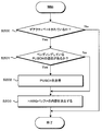
- FIG. 9 is a flowchart showing an example of the operation of the mobile station apparatus 1 according to the second embodiment of the present invention.
- the mobile station apparatus 1 performs the process of FIG. 9 for each HARQ process.
- the mobile station apparatus 1 determines whether the downlink component carrier in which the PHICH (HARQ indicator) and the PDCCH (uplink grant) are arranged for the HARQ process related to a certain uplink component carrier is deactivated. Determination is made (step S200).
- step S200 the mobile station apparatus 1 determines that all downlink component carriers in which PHICH (HARQ indicator) and PDCCH (uplink grant) for the HARQ process related to a certain uplink component carrier are arranged are deactivated. If so, it is determined whether there is a pending PUSCH transmission (step S201).
- PHICH HARQ indicator
- PDCCH uplink grant
- step S201 If the mobile station apparatus 1 determines that there is a pending PUSCH transmission in step S201, after transmitting the pending PUSCH (step S202), the HARQ buffer related to this uplink component carrier Is deleted (step S203). If the mobile station apparatus 1 determines in step S201 that there is no pending PUSCH transmission, the mobile station apparatus 1 proceeds to step S203 and deletes the contents of the HARQ buffer related to this uplink component carrier.
- step S200 If the mobile station apparatus 1 determines in step S200 that all downlink component carriers in which PHICH (HARQ indicator) and PDCCH (uplink grant) for the HARQ process related to a certain uplink component carrier are arranged have been deactivated. Without performing steps S201 and S202, the transmission of the PUSCH of the uplink component carrier may be canceled in the subsequent subframe, and the content of the HARQ buffer may be erased (step S203). After step S203, the mobile station apparatus 1 ends the process. The mobile station apparatus 1 has at least one downlink component carrier in which PHICH (HARQ indicator) and PDCCH (uplink grant) for the HARQ process related to the uplink component carrier are not deactivated in step S200. If it is determined that there is one, the process is terminated.
- PHICH HARQ indicator
- PDCCH uplink grant
- the upper layer processing unit 101 of the mobile station apparatus 1 is different. However, since the configuration and functions of other components are the same as those in the first embodiment, description of the same functions as those in the first embodiment is omitted.
- the HARQ control unit 1013 of the higher layer processing unit 101 of the mobile station apparatus 1 performs HARQ when the downlink component carrier in which the PHICH (HARQ indicator) for the uplink component carrier is arranged is deactivated. Do not set ACK as HARQ feedback for process. Then, the HARQ control unit 1013 includes the HARQ storage unit 1015 when all downlink component carriers in which PHICH (HARQ indicator) and PDCCH (uplink grant) are arranged for the uplink component carrier are deactivated. The contents of the HARQ buffer related to the uplink component carrier are deleted.
- the mobile station apparatus 1 may change the timing of erasing the contents of the HARQ buffer according to how the downlink component carrier is deactivated.
- the mobile station apparatus 1 receives a downlink component carrier notified not to be used for downlink communication by an activation command for a predetermined time after receiving the activation command (for example, 4 ms, 4 subframes, 4 TTI).
- a predetermined time eg, 100 ms, 100 subframes, 100 TTI
- a predetermined time eg, 100 ms, 100 subframes, 100 TTI
- a method of deactivating a component carrier when a predetermined time (for example, 10 ms, 10 subframes, 10 TTI) has elapsed since the last reception of PDCCH or PDSCH on an activated downlink component carrier, A method of deactivating a downlink component carrier (hereinafter, a method other than a method of performing deactivation after a predetermined time after receiving an activation command is referred to as Implicit deactivation) is used.
- a predetermined time for example, 10 ms, 10 subframes, 10 TTI
- the base station device 3 notifies the mobile station device 1 of an activation command or maintains the activated state when it wants to keep the downlink component carrier that is deactivated after a predetermined time by the inactivity deactivation in the activated state.
- the PDCCH or PDSCH is transmitted to the mobile station apparatus 1 on the downlink component carrier to be continued.
- the mobile station device 1 has a timer that measures the passage of time since activation of the downlink component carrier by the activation command, and the passage of time since the last reception of PDCCH or PDSCH on the activated downlink component carrier.
- the mobile station apparatus 1 erases the content of the HARQ buffer when the downlink component carrier is deactivated.
- the mobile station apparatus 1 deactivates the downlink component carrier and then performs a predetermined operation.
- the contents of the HARQ buffer may be erased after a lapse of time.
- the base station apparatus 3 wants to continue uplink communication (retransmission of PUSCH), the activation command cannot be notified to the mobile station apparatus 1 without error, or PDCCH and PDSCH are transmitted. Even when the mobile station apparatus 1 cannot properly transmit to the mobile station apparatus 1 and the mobile station apparatus 1 deactivates the downlink component carrier due to the Initiate Deactivation, the mobile station apparatus 1 remains in the HARQ buffer for a predetermined time. Therefore, the base station apparatus 3 activates the downlink component carrier that has been deactivated by using the activation command, and transmits the downlink component carrier that activates the uplink grant that instructs retransmission. by doing, It can be performed immediately retransmission of PUSCH in Dokyoku device 1.
- the mobile station apparatus 1 leaves control of the base station apparatus 3 unnecessary when all downlink component carriers that receive PHICH (HARQ indicator) and PDCCH (uplink grant) have been deactivated. Therefore, it is possible to efficiently perform PUSCH retransmission control by avoiding re-transmission of PUSCH.
- PHICH HARQ indicator
- PDCCH uplink grant
- the present invention is also applicable to the case where all downlink component carriers that receive PHICH (HARQ indicator) and PDCCH (uplink grant) are excluded from the setting of downlink component carriers used for communication using RRC signals.
- the same effect can be obtained by applying. That is, when all downlink component carriers receiving PHICH (HARQ indicator) and PDCCH (uplink grant) are excluded from the setting, the mobile station apparatus 1 includes the contents of the HARQ buffer related to the uplink component carrier. Erase.
- the present invention is set using the RRC signal if the downlink component carrier from which the PHICH for a certain uplink component carrier is received is not the downlink component carrier in which the uplink grant for the uplink component carrier is arranged. It may be applied to That is, when the downlink component carrier on which PHICH is received is excluded from the downlink component carriers on which the uplink grant is arranged, the mobile station apparatus 1 sets ACK to the corresponding HARQ process.
- the mobile station apparatus 1 uses the uplink grant for UL CC-1 and The PHICH is received by DL CC-1.
- the base station apparatus 3 resets the downlink component carrier for transmitting the uplink grant for UL CC-1 to DL CC-2, and the mobile station device
- the mobile station apparatus 1 receives the PHICH for the UL-CC-1 in the DL-CC-1 and monitors the uplink grant for the UL-CC-1 in the DL-CC-2.
- the load of the reception process of the mobile station device 1 increases.
- the base station device 3 transmits the downlink component carrier that transmits the uplink grant for the UL CC-1 to the DL CC.
- -2 is reset, and when the mobile station apparatus 1 applies this setting, the mobile station apparatus 1 deletes the contents of the HARQ buffer related to the HARQ process of UL ⁇ CC-1 and the PHICH of DL ⁇ CC-1 Therefore, only the uplink grant of DL CC-2 is monitored without performing the receiving process, so the load of the receiving process of the mobile station apparatus 1 can be reduced.
- the radio communication system of the present invention is a radio communication system in which a mobile station apparatus and a base station apparatus communicate with each other using a plurality of downlink component carriers, and an uplink transmitted from the mobile station apparatus to the base station apparatus
- the mobile station apparatus sets ACK without receiving the HARQ indicator, and the base station apparatus , It is determined that ACK is set without receiving the HARQ indicator.
- wireless communications system of this invention is a radio
- the mobile station apparatus of the present invention is a mobile station apparatus that communicates with a base station apparatus using a plurality of downlink component carriers, and receives a HARQ indicator for uplink data transmitted to the base station apparatus.
- a downlink component carrier to be activated is deactivated, ACK is set without receiving the HARQ indicator.
- the mobile station apparatus of this invention is a mobile station apparatus which communicates with a base station apparatus using a some downlink component carrier, and receives the HARQ indicator with respect to the uplink data transmitted to the said base station apparatus
- a downlink component carrier to be deactivated When a downlink component carrier to be deactivated is deactivated, the buffer content for the uplink data is erased without receiving the HARQ indicator.
- the base station apparatus of this invention is a base station apparatus which communicates with a mobile station apparatus using a some downlink component carrier, The uplink data which the said mobile station apparatus transmitted to the said base station apparatus When the downlink component carrier that receives the HARQ indicator is deactivated, the mobile station apparatus does not receive the HARQ indicator and determines that ACK is set.
- the base station apparatus of this invention is a base station apparatus which communicates with a mobile station apparatus using a some downlink component carrier, The uplink data which the said mobile station apparatus transmitted to the said base station apparatus
- the mobile station apparatus determines that the content of the buffer for the uplink data has been deleted without receiving the HARQ indicator. It is said.
- the radio communication method of the present invention is a radio communication method used for a mobile station apparatus that communicates with a base station apparatus using a plurality of downlink component carriers, and the uplink transmitted to the base station apparatus
- the downlink component carrier that receives the HARQ indicator for data has means for setting an ACK without receiving the HARQ indicator.
- the radio communication method of the present invention is a radio communication method used for a mobile station apparatus that communicates with a base station apparatus using a plurality of downlink component carriers, and the uplink transmitted to the base station apparatus
- the downlink component carrier that receives the HARQ indicator for the data When the downlink component carrier that receives the HARQ indicator for the data is deactivated, it has means for erasing the contents of the buffer for the uplink data without receiving the HARQ indicator.
- the radio communication method of the present invention is a radio communication method used for a base station apparatus that communicates with a mobile station apparatus using a plurality of downlink component carriers, and the mobile station apparatus is the base station apparatus.
- the mobile station apparatus has means for determining that the ACK is set without receiving the HARQ indicator. It is characterized by.
- the radio communication method of the present invention is a radio communication method used for a base station apparatus that communicates with a mobile station apparatus using a plurality of downlink component carriers, and the mobile station apparatus is the base station apparatus.
- the downlink component carrier that receives the HARQ indicator for the uplink data transmitted to is deactivated, the mobile station apparatus has erased the contents of the buffer for the uplink data without receiving the HARQ indicator It has the means to judge that.
- the integrated circuit of the present invention is an integrated circuit used in a mobile station apparatus that communicates with a base station apparatus using a plurality of downlink component carriers, and for the uplink data transmitted to the base station apparatus When the downlink component carrier that receives the HARQ indicator is deactivated, it has means for setting ACK without receiving the HARQ indicator.
- An integrated circuit according to the present invention is an integrated circuit used in a mobile station apparatus that communicates with a base station apparatus using a plurality of downlink component carriers, and for the uplink data transmitted to the base station apparatus.
- the downlink component carrier that receives the HARQ indicator has been deactivated, it has means for erasing the contents of the buffer for the uplink data without receiving the HARQ indicator.
- An integrated circuit of the present invention is an integrated circuit used in a base station apparatus that communicates with a mobile station apparatus using a plurality of downlink component carriers, and the mobile station apparatus transmits to the base station apparatus.
- the mobile station apparatus When the downlink component carrier that receives the HARQ indicator for the uplink data is deactivated, the mobile station apparatus has means for determining that the ACK is set without receiving the HARQ indicator. It is said.
- the integrated circuit of the present invention is an integrated circuit used in a base station apparatus that communicates with a mobile station apparatus using a plurality of downlink component carriers, and the mobile station apparatus transmits to the base station apparatus.
- the downlink component carrier that receives the HARQ indicator for the uplink data is deactivated, it is determined that the mobile station apparatus has erased the contents of the buffer for the uplink data without receiving the HARQ indicator It has the means to do.
- a program that operates in the base station apparatus 3 and the mobile station apparatus 1 related to the present invention is a program (computer functions as a computer) that controls a CPU (Central Processing Unit) so as to realize the functions of the above-described embodiments related to the present invention.
- Program Information handled by these devices is temporarily accumulated in RAM (Random Access Memory) during the processing, and then stored in various ROMs such as Flash ROM (Read Only Memory) and HDD (Hard Disk Drive). Reading, correction, and writing are performed by the CPU as necessary.
- the program for realizing the control function may be recorded on a computer-readable recording medium, and the program recorded on the recording medium may be read by the computer system and executed.
- the “computer system” here is a computer system built in the mobile station apparatus 1 or the base station apparatus 3 and includes an OS and hardware such as peripheral devices.
- the “computer-readable recording medium” means a storage device such as a flexible disk, a magneto-optical disk, a portable medium such as a ROM and a CD-ROM, and a hard disk incorporated in a computer system.
- the “computer-readable recording medium” is a medium that dynamically holds a program for a short time, such as a communication line when transmitting a program via a network such as the Internet or a communication line such as a telephone line, In such a case, a volatile memory inside a computer system serving as a server or a client may be included and a program that holds a program for a certain period of time.
- the program may be a program for realizing a part of the functions described above, and may be a program capable of realizing the functions described above in combination with a program already recorded in a computer system.
- part or all of the mobile station device 1 and the base station device 3 in the above-described embodiment may be realized as an LSI that is typically an integrated circuit.
- Each functional block of the mobile station device 1 and the base station device 3 may be individually chipped, or a part or all of them may be integrated into a chip.
- the method of circuit integration is not limited to LSI, and may be realized by a dedicated circuit or a general-purpose processor.
- an integrated circuit based on the technology can also be used.
Abstract
Description
以下、図面を参照しながら本発明の第1の実施形態について詳しく説明する。 (First embodiment)
Hereinafter, a first embodiment of the present invention will be described in detail with reference to the drawings.
以下、図面を参照しながら本発明の第2の実施形態について詳しく説明する。 (Second Embodiment)
Hereinafter, a second embodiment of the present invention will be described in detail with reference to the drawings.
3 基地局装置
101 上位層処理部
103 制御部
105 受信部
107 送信部
301 上位層処理部
303 制御部
305 受信部
307 送信部
1011 無線リソース制御部
1013 HARQ制御部
1015 HARQ記憶部
3011 無線リソース制御部
3013 HARQ制御部
3015 HARQ記憶部 1 (1A, 1B, 1C)
Claims (15)
- 複数の下りリンクコンポーネントキャリアおよび複数の上りリンクコンポーネントキャリアを用いて基地局装置と通信をする移動局装置に用いられる無線通信方法において、
前記上りリンクコンポーネントキャリアに対する下りリンクコンポーネントキャリアを下りリンクの通信に用いないように設定した際に、前記下りリンクの通信に用いないように設定した下りリンクコンポーネントキャリアに関連する、上りリンクコンポーネントキャリアのHARQバッファの内容を消去するステップを含むことを特徴とする無線通信方法。 In a radio communication method used for a mobile station apparatus that communicates with a base station apparatus using a plurality of downlink component carriers and a plurality of uplink component carriers,
When the downlink component carrier for the uplink component carrier is set not to be used for downlink communication, an uplink component carrier related to the downlink component carrier set not to be used for downlink communication is set. A wireless communication method comprising: erasing the contents of a HARQ buffer. - 複数の下りリンクコンポーネントキャリアおよび複数の上りリンクコンポーネントキャリアを用いて基地局装置と通信をする移動局装置において、
前記上りリンクコンポーネントキャリアに対する下りリンクコンポーネントキャリアを下りリンクの通信に用いないように設定した際に、前記下りリンクの通信に用いないように設定した下りリンクコンポーネントキャリアに関連する、上りリンクコンポーネントキャリアのHARQバッファの内容を消去することを特徴とする移動局装置。 In a mobile station apparatus that communicates with a base station apparatus using a plurality of downlink component carriers and a plurality of uplink component carriers,
When the downlink component carrier for the uplink component carrier is set not to be used for downlink communication, an uplink component carrier related to the downlink component carrier set not to be used for downlink communication is set. A mobile station apparatus that erases the contents of a HARQ buffer. - 複数の下りリンクコンポーネントキャリアおよび複数の上りリンクコンポーネントキャリアを用いて移動局装置と基地局装置が通信をする無線通信システムにおいて、
前記移動局装置は、
前記上りリンクコンポーネントキャリアに対する下りリンクコンポーネントキャリアを下りリンクの通信に用いないように設定した際に、前記下りリンクの通信に用いないように設定した下りリンクコンポーネントキャリアに関連する、上りリンクコンポーネントキャリアのHARQバッファの内容を消去し、
前記基地局装置は、
前記移動局装置が、前記上りリンクコンポーネントキャリアに対する下りリンクコンポーネントキャリアを下りリンクの通信に用いないように設定した際に、前記下りリンクの通信に用いないように設定した下りリンクコンポーネントキャリアに関連する、上りリンクコンポーネントキャリアのHARQバッファの内容を消去したと判断することを特徴とする無線通信システム。 In a wireless communication system in which a mobile station apparatus and a base station apparatus communicate using a plurality of downlink component carriers and a plurality of uplink component carriers,
The mobile station device
When the downlink component carrier for the uplink component carrier is set not to be used for downlink communication, an uplink component carrier related to the downlink component carrier set not to be used for downlink communication is set. Erase the contents of the HARQ buffer,
The base station device
When the mobile station apparatus is set not to use the downlink component carrier for the uplink component carrier for downlink communication, the mobile station apparatus relates to the downlink component carrier set not to use for the downlink communication A radio communication system characterized by determining that the content of the HARQ buffer of the uplink component carrier has been deleted. - 複数の下りリンクコンポーネントキャリアおよび複数の上りリンクコンポーネントキャリアを用いて基地局装置と通信をする移動局装置に用いられる集積回路において、
前記上りリンクコンポーネントキャリアに対する下りリンクコンポーネントキャリアを下りリンクの通信に用いないように設定した際に、前記下りリンクの通信に用いないように設定した下りリンクコンポーネントキャリアに関連する、上りリンクコンポーネントキャリアのHARQバッファの内容を消去する機能を有することを特徴とする集積回路。 In an integrated circuit used in a mobile station apparatus that communicates with a base station apparatus using a plurality of downlink component carriers and a plurality of uplink component carriers,
When the downlink component carrier for the uplink component carrier is set not to be used for downlink communication, an uplink component carrier related to the downlink component carrier set not to be used for downlink communication is set. An integrated circuit having a function of erasing the contents of a HARQ buffer. - 複数の下りリンクコンポーネントキャリアおよび複数の上りリンクコンポーネントキャリアを用いて基地局装置と通信をする移動局装置に用いられる無線通信方法において、
前記上りリンクコンポーネントキャリアに対する下りリンクコンポーネントキャリアをデアクティベートした際に、前記デアクティベートした下りリンクコンポーネントキャリアに関連する、上りリンクコンポーネントキャリアのHARQバッファの内容を消去するステップを含むことを特徴とする無線通信方法。 In a radio communication method used for a mobile station apparatus that communicates with a base station apparatus using a plurality of downlink component carriers and a plurality of uplink component carriers,
And deleting the contents of the HARQ buffer of the uplink component carrier related to the deactivated downlink component carrier when the downlink component carrier for the uplink component carrier is deactivated. Communication method. - 前記基地局装置から送信されるコマンドによって通知された際に、下りリンクコンポーネントキャリアをデアクティベートするステップを含むことを特徴とする請求項5に記載の無線通信方法。 The wireless communication method according to claim 5, further comprising a step of deactivating a downlink component carrier when notified by a command transmitted from the base station apparatus.
- 前記基地局装置から送信されるコマンドによって通知され、下りリンクコンポーネントキャリアをアクティベートしてから所定の時間が経過した場合に、前記アクティベートした下りリンクコンポーネントキャリアをデアクティベートするステップを含むことを特徴とする請求項5に記載の無線通信方法。 Deactivating the activated downlink component carrier when a predetermined time elapses after activation of the downlink component carrier notified by a command transmitted from the base station apparatus, The wireless communication method according to claim 5.
- 前記基地局装置から送信される物理下りリンク制御チャネルを下りリンクコンポーネントキャリアで受信してから所定の時間が経過した場合に、前記物理下りリンク制御チャネルを受信した下りリンクコンポーネントキャリアをデアクティベートするステップを含むことを特徴とする請求項5に記載の無線通信方法。 Deactivating the downlink component carrier that has received the physical downlink control channel when a predetermined time has elapsed since the physical downlink control channel transmitted from the base station apparatus was received by the downlink component carrier The wireless communication method according to claim 5, further comprising:
- 複数の下りリンクコンポーネントキャリアおよび複数の上りリンクコンポーネントキャリアを用いて基地局装置と通信をする移動局装置において、
前記上りリンクコンポーネントキャリアに対する下りリンクコンポーネントキャリアをデアクティベートした際に、前記デアクティベートした下りリンクコンポーネントキャリアに関連する、上りリンクコンポーネントキャリアのHARQバッファの内容を消去することを特徴とする移動局装置。 In a mobile station apparatus that communicates with a base station apparatus using a plurality of downlink component carriers and a plurality of uplink component carriers,
A mobile station apparatus, wherein when a downlink component carrier for the uplink component carrier is deactivated, the content of the HARQ buffer of the uplink component carrier related to the deactivated downlink component carrier is erased. - 複数の下りリンクコンポーネントキャリアおよび複数の上りリンクコンポーネントキャリアを用いて移動局装置と基地局装置が通信をする無線通信システムにおいて、
前記移動局装置は、
前記上りリンクコンポーネントキャリアに対する下りリンクコンポーネントキャリアをデアクティベートした際に、前記デアクティベートした下りリンクコンポーネントキャリアに関連する、上りリンクコンポーネントキャリアのHARQバッファの内容を消去し、
前記基地局装置は、
前記移動局装置が、前記上りリンクコンポーネントキャリアに対する下りリンクコンポーネントキャリアをデアクティベートした際に、前記デアクティベートした下りリンクコンポーネントキャリアに関連する、上りリンクコンポーネントキャリアのHARQバッファの内容を消去したと判断することを特徴とする無線通信システム。 In a wireless communication system in which a mobile station apparatus and a base station apparatus communicate using a plurality of downlink component carriers and a plurality of uplink component carriers,
The mobile station device
When deactivating the downlink component carrier for the uplink component carrier, erase the HARQ buffer content of the uplink component carrier related to the deactivated downlink component carrier;
The base station device
When the mobile station apparatus deactivates the downlink component carrier for the uplink component carrier, it determines that the content of the HARQ buffer of the uplink component carrier related to the deactivated downlink component carrier has been deleted. A wireless communication system. - 複数の下りリンクコンポーネントキャリアおよび複数の上りリンクコンポーネントキャリアを用いて基地局装置と通信をする移動局装置に用いられる集積回路において、
前記上りリンクコンポーネントキャリアに対する下りリンクコンポーネントキャリアをデアクティベートした際に、前記デアクティベートした下りリンクコンポーネントキャリアに関連する、上りリンクコンポーネントキャリアのHARQバッファの内容を消去する機能を有することを特徴とする集積回路。 In an integrated circuit used in a mobile station apparatus that communicates with a base station apparatus using a plurality of downlink component carriers and a plurality of uplink component carriers,
An integration having a function of erasing the content of the HARQ buffer of the uplink component carrier related to the deactivated downlink component carrier when the downlink component carrier for the uplink component carrier is deactivated circuit. - 複数の下りリンクコンポーネントキャリアを用いて基地局装置と通信をする移動局装置に用いられる無線通信方法において、
前記基地局装置に送信した上りリンクデータに対するHARQインディケータを受信する下りリンクコンポーネントキャリアがデアクティベートされている場合は、前記HARQインディケータを受信せずに、ACKをセットするステップを含むことを特徴とする無線通信方法。 In a radio communication method used for a mobile station apparatus that communicates with a base station apparatus using a plurality of downlink component carriers,
When a downlink component carrier that receives a HARQ indicator for uplink data transmitted to the base station apparatus is deactivated, the method includes a step of setting ACK without receiving the HARQ indicator. Wireless communication method. - 複数の下りリンクコンポーネントキャリアを用いて基地局装置と通信をする移動局装置において、
前記基地局装置に送信した上りリンクデータに対するHARQインディケータを受信する下りリンクコンポーネントキャリアがデアクティベートされている場合は、前記HARQインディケータを受信せずに、ACKをセットすることを特徴とする移動局装置。 In a mobile station apparatus that communicates with a base station apparatus using a plurality of downlink component carriers,
A mobile station apparatus that sets ACK without receiving the HARQ indicator when a downlink component carrier that receives a HARQ indicator for uplink data transmitted to the base station apparatus is deactivated. . - 複数の下りリンクコンポーネントキャリアを用いて移動局装置と基地局装置が通信をする無線通信システムにおいて、
前記移動局装置が前記基地局装置に送信した上りリンクデータに対するHARQインディケータを受信する下りリンクコンポーネントキャリアがデアクティベートされている場合は、
前記移動局装置は、前記HARQインディケータを受信せずに、ACKをセットし、
前記基地局装置は、前記移動局装置が前記HARQインディケータを受信せずに、ACKをセットしたと判断することを特徴とする無線通信システム。 In a wireless communication system in which a mobile station apparatus and a base station apparatus communicate using a plurality of downlink component carriers,
When the downlink component carrier that receives the HARQ indicator for the uplink data transmitted from the mobile station device to the base station device is deactivated,
The mobile station apparatus does not receive the HARQ indicator, sets ACK,
The base station apparatus determines that the mobile station apparatus has set ACK without receiving the HARQ indicator. - 複数の下りリンクコンポーネントキャリアを用いて基地局装置と通信をする移動局装置に用いられる集積回路において、
前記基地局装置に送信した上りリンクデータに対するHARQインディケータを受信する下りリンクコンポーネントキャリアがデアクティベートされている場合は、前記HARQインディケータを受信せずに、ACKをセットする機能を有することを特徴とする集積回路。 In an integrated circuit used in a mobile station apparatus that communicates with a base station apparatus using a plurality of downlink component carriers,
When a downlink component carrier that receives a HARQ indicator for uplink data transmitted to the base station apparatus is deactivated, it has a function of setting ACK without receiving the HARQ indicator. Integrated circuit.
Priority Applications (4)
| Application Number | Priority Date | Filing Date | Title |
|---|---|---|---|
| KR1020127028005A KR101421863B1 (en) | 2010-03-30 | 2011-03-25 | Wireless communication method, mobile station device, wireless communication system, and integrated circuit |
| US13/635,752 US9686047B2 (en) | 2010-03-30 | 2011-03-25 | Wireless communication method, mobile station apparatus, wireless communication system and integrated circuit |
| CN201180016732.4A CN102823290B (en) | 2010-03-30 | 2011-03-25 | Wireless communications method, mobile station apparatus, wireless communication system and integrated circuit |
| EP11762726.5A EP2555557B1 (en) | 2010-03-30 | 2011-03-25 | Wireless communication method, mobile station device, wireless communication system, and integrated circuit |
Applications Claiming Priority (2)
| Application Number | Priority Date | Filing Date | Title |
|---|---|---|---|
| JP2010-077447 | 2010-03-30 | ||
| JP2010077447A JP4823371B2 (en) | 2010-03-30 | 2010-03-30 | Wireless communication system, mobile station apparatus, base station apparatus, wireless communication method, and integrated circuit |
Publications (1)
| Publication Number | Publication Date |
|---|---|
| WO2011122495A1 true WO2011122495A1 (en) | 2011-10-06 |
Family
ID=44712201
Family Applications (1)
| Application Number | Title | Priority Date | Filing Date |
|---|---|---|---|
| PCT/JP2011/057455 WO2011122495A1 (en) | 2010-03-30 | 2011-03-25 | Wireless communication method, mobile station device, wireless communication system, and integrated circuit |
Country Status (7)
| Country | Link |
|---|---|
| US (1) | US9686047B2 (en) |
| EP (1) | EP2555557B1 (en) |
| JP (1) | JP4823371B2 (en) |
| KR (1) | KR101421863B1 (en) |
| CN (1) | CN102823290B (en) |
| TW (1) | TWI466485B (en) |
| WO (1) | WO2011122495A1 (en) |
Cited By (1)
| Publication number | Priority date | Publication date | Assignee | Title |
|---|---|---|---|---|
| CN103906113A (en) * | 2012-12-28 | 2014-07-02 | 联芯科技有限公司 | Method for judging user terminal falsely detected uplink dispatching control information |
Families Citing this family (15)
| Publication number | Priority date | Publication date | Assignee | Title |
|---|---|---|---|---|
| CN102291770B (en) * | 2010-06-21 | 2014-07-30 | 上海贝尔股份有限公司 | Method and device for optimizing user plane operation in communication system based on carrier aggregation |
| CN102447550B (en) * | 2010-09-30 | 2014-07-16 | 上海贝尔股份有限公司 | Method and device for processing mixed automatic retransmitting request |
| JP5009410B2 (en) | 2010-10-29 | 2012-08-22 | シャープ株式会社 | Mobile station apparatus, radio communication method, and integrated circuit |
| CN103918211A (en) | 2011-11-01 | 2014-07-09 | Lg电子株式会社 | Method and apparatus for receiving ACK/NACK in wireless communication system |
| JP5883403B2 (en) * | 2013-01-31 | 2016-03-15 | 株式会社Nttドコモ | User terminal, radio base station, and radio communication method |
| US10903943B2 (en) * | 2014-06-13 | 2021-01-26 | Apple Inc. | Enhanced LTE UL HARQ feedback indication for power saving and range improvement |
| JP6370930B2 (en) * | 2015-01-29 | 2018-08-08 | 株式会社Nttドコモ | Terminal |
| EP3292647B1 (en) * | 2015-05-06 | 2021-07-07 | Telefonaktiebolaget LM Ericsson (publ) | Inserting and extracting control data using frequency components |
| US10630410B2 (en) | 2016-05-13 | 2020-04-21 | Telefonaktiebolaget Lm Ericsson (Publ) | Network architecture, methods, and devices for a wireless communications network |
| US10367677B2 (en) | 2016-05-13 | 2019-07-30 | Telefonaktiebolaget Lm Ericsson (Publ) | Network architecture, methods, and devices for a wireless communications network |
| US10708938B2 (en) | 2016-10-31 | 2020-07-07 | Samsung Electronics Co., Ltd. | Transmission of UL control channels with dynamic structures |
| JP6793749B2 (en) * | 2016-11-18 | 2020-12-02 | シャープ株式会社 | Terminal equipment, base station equipment, communication methods, and integrated circuits |
| US10958407B2 (en) * | 2017-06-09 | 2021-03-23 | Qualcomm Incorporated | Frequency division duplexing hybrid automatic repeat request with mini-slots |
| US11817947B2 (en) * | 2017-09-15 | 2023-11-14 | Telefonaktiebolaget Lm Ericsson (Publ) | Code-rate-dependent modulation techniques |
| CN116996981A (en) | 2017-09-28 | 2023-11-03 | 联想(新加坡)私人有限公司 | Transmit power control commands for transmit power adjustment |
Citations (1)
| Publication number | Priority date | Publication date | Assignee | Title |
|---|---|---|---|---|
| JP2009232132A (en) * | 2008-03-21 | 2009-10-08 | Ntt Docomo Inc | Mobile station and base station device |
Family Cites Families (32)
| Publication number | Priority date | Publication date | Assignee | Title |
|---|---|---|---|---|
| US7768962B2 (en) * | 2005-11-01 | 2010-08-03 | Nokia Corporation | HSUPA HARQ process flushing |
| US20090086657A1 (en) * | 2007-10-01 | 2009-04-02 | Comsys Communication & Signal Processing Ltd. | Hybrid automatic repeat request buffer flushing mechanism |
| KR20140044404A (en) * | 2008-03-21 | 2014-04-14 | 인터디지탈 패튼 홀딩스, 인크 | Method and apparatus for performing a serving hs-dsch cell change |
| US8711785B2 (en) * | 2008-03-25 | 2014-04-29 | Qualcomm Incorporated | Fast carrier allocation in multi-carrier systems |
| WO2009132290A2 (en) * | 2008-04-25 | 2009-10-29 | Interdigital Patent Holdings, Inc. | Method and apparatus for simultaneously receiving on two carriers and performing discontinuous transmission and reception in dual cell high speed downlink packet access |
| WO2009132203A1 (en) | 2008-04-25 | 2009-10-29 | Interdigital Patent Holdings, Inc. | Harq process utilization in multiple carrier wireless communications |
| KR101468742B1 (en) * | 2008-05-06 | 2014-12-04 | 엘지전자 주식회사 | A method for transmitting data in a wireless communication system |
| EP2131517A3 (en) * | 2008-06-03 | 2010-01-20 | Innovative Sonic Limited | Method and apparatus for improving HARQ uplink transmission |
| US8295217B2 (en) * | 2008-07-11 | 2012-10-23 | Acer Incorporated | Method and apparatus for a device power savings class |
| JP5154523B2 (en) * | 2008-08-27 | 2013-02-27 | 創新音▲速▼股▲ふん▼有限公司 | Method and apparatus for processing HARQ process of SPS function |
| US8274969B2 (en) * | 2008-10-31 | 2012-09-25 | Htc Corporation | Method for improving random access procedure in wireless communications system and related communication device |
| TWM385878U (en) * | 2008-11-10 | 2010-08-01 | Interdigital Patent Holdings | Apparatus for enabling and disabling a supplementary downlink carrier |
| US20100130137A1 (en) * | 2008-11-21 | 2010-05-27 | Interdigital Patent Holdings, Inc. | Method and apparatus for multiple carrier utilization in wireless communications |
| KR20120048044A (en) * | 2008-11-25 | 2012-05-14 | 인터디지탈 패튼 홀딩스, 인크 | Method and apparatus for utilizing a plurality of uplink carriers and a plurality of downlink carriers |
| US20110002281A1 (en) * | 2008-12-30 | 2011-01-06 | Interdigital Patent Holdings, Inc. | Discontinuous reception for carrier aggregation |
| US8867666B2 (en) * | 2009-02-06 | 2014-10-21 | Lg Electronics Inc. | Device and method supporting multi-carrier waves |
| KR20130088174A (en) * | 2009-03-12 | 2013-08-07 | 인터디지탈 패튼 홀딩스, 인크 | Method and apparatus for monitoring for a radio link failure |
| US20100254329A1 (en) * | 2009-03-13 | 2010-10-07 | Interdigital Patent Holdings, Inc. | Uplink grant, downlink assignment and search space method and apparatus in carrier aggregation |
| US20100302951A1 (en) * | 2009-05-26 | 2010-12-02 | Ou Meng-Hui | Method and Apparatus for Handling Radio Link Failure |
| US20110003555A1 (en) * | 2009-07-06 | 2011-01-06 | Yu-Hsuan Guo | Method and Apparatus for PDCCH Monitoring |
| US8386875B2 (en) * | 2009-08-07 | 2013-02-26 | Research In Motion Limited | Method and system for handling HARQ operations during transmission mode changes |
| CA2775305C (en) * | 2009-09-25 | 2017-07-11 | Research In Motion Limited | System and method for multi-carrier network operation |
| CN102640547A (en) * | 2009-10-02 | 2012-08-15 | 诺基亚西门子通信公司 | Timing control |
| CN102577222B (en) * | 2009-10-13 | 2015-01-28 | 瑞典爱立信有限公司 | Method and arrangement in a communication system |
| WO2011063244A2 (en) * | 2009-11-19 | 2011-05-26 | Interdigital Patent Holdings, Inc. | Component carrier activation/deactivation in multi-carrier systems |
| MY163403A (en) * | 2010-01-08 | 2017-09-15 | Interdigital Patent Holdings Inc | Maintaining time alignment with multiple uplink carriers |
| EP2360864A1 (en) * | 2010-02-12 | 2011-08-24 | Panasonic Corporation | Component carrier (de)activation in communication systems using carrier aggregation |
| EP2360866A1 (en) * | 2010-02-12 | 2011-08-24 | Panasonic Corporation | Component carrier activation and deactivation using resource assignments |
| EP2388944A1 (en) * | 2010-03-25 | 2011-11-23 | Innovative Sonic Corporation | Method and apparatus for component carrier deactivation in a wireless communication system |
| US9363059B2 (en) * | 2010-04-02 | 2016-06-07 | Acer Incorporated | Method of handling component carrier activation and deactivation and communication device thereof |
| CN102291770B (en) * | 2010-06-21 | 2014-07-30 | 上海贝尔股份有限公司 | Method and device for optimizing user plane operation in communication system based on carrier aggregation |
| US8946697B1 (en) * | 2012-11-09 | 2015-02-03 | Universal Display Corporation | Iridium complexes with aza-benzo fused ligands |
-
2010
- 2010-03-30 JP JP2010077447A patent/JP4823371B2/en active Active
-
2011
- 2011-03-25 KR KR1020127028005A patent/KR101421863B1/en active IP Right Grant
- 2011-03-25 US US13/635,752 patent/US9686047B2/en active Active
- 2011-03-25 CN CN201180016732.4A patent/CN102823290B/en active Active
- 2011-03-25 EP EP11762726.5A patent/EP2555557B1/en active Active
- 2011-03-25 WO PCT/JP2011/057455 patent/WO2011122495A1/en active Application Filing
- 2011-03-30 TW TW100111102A patent/TWI466485B/en active
Patent Citations (1)
| Publication number | Priority date | Publication date | Assignee | Title |
|---|---|---|---|---|
| JP2009232132A (en) * | 2008-03-21 | 2009-10-08 | Ntt Docomo Inc | Mobile station and base station device |
Non-Patent Citations (3)
| Title |
|---|
| "Open issues on component carrier activation and deactivation", 3GPP TSG RAN WG2 MEETING, 22 February 2010 (2010-02-22) |
| SAMSUNG: "Component carrier activation and deactivation, Rl-101144", 3GPP, 26 February 2010 (2010-02-26), XP050418688 * |
| See also references of EP2555557A4 |
Cited By (2)
| Publication number | Priority date | Publication date | Assignee | Title |
|---|---|---|---|---|
| CN103906113A (en) * | 2012-12-28 | 2014-07-02 | 联芯科技有限公司 | Method for judging user terminal falsely detected uplink dispatching control information |
| CN103906113B (en) * | 2012-12-28 | 2017-11-10 | 联芯科技有限公司 | Judge the method for the empty inspection uplink scheduling control information of user terminal |
Also Published As
| Publication number | Publication date |
|---|---|
| KR20120131234A (en) | 2012-12-04 |
| TWI466485B (en) | 2014-12-21 |
| CN102823290A (en) | 2012-12-12 |
| EP2555557A1 (en) | 2013-02-06 |
| US9686047B2 (en) | 2017-06-20 |
| JP2011211494A (en) | 2011-10-20 |
| CN102823290B (en) | 2015-12-02 |
| JP4823371B2 (en) | 2011-11-24 |
| EP2555557B1 (en) | 2017-03-22 |
| TW201215029A (en) | 2012-04-01 |
| US20130051341A1 (en) | 2013-02-28 |
| EP2555557A4 (en) | 2013-10-23 |
| KR101421863B1 (en) | 2014-07-22 |
Similar Documents
| Publication | Publication Date | Title |
|---|---|---|
| JP4823371B2 (en) | Wireless communication system, mobile station apparatus, base station apparatus, wireless communication method, and integrated circuit | |
| JP6499976B2 (en) | Terminal apparatus, base station apparatus, and communication method | |
| WO2011125483A1 (en) | Mobile station apparatus, wireless communication method and integrated circuit | |
| JP6380956B2 (en) | Terminal apparatus, base station apparatus, integrated circuit, and communication method | |
| JP6131458B2 (en) | Mobile station apparatus, base station apparatus, and radio communication method | |
| JP6240976B2 (en) | Terminal apparatus, base station apparatus, integrated circuit, and communication method | |
| WO2011148876A1 (en) | Mobile station apparatus, base station apparatus, wireless communication system, wireless communication method and integrated circuit | |
| JP6452048B2 (en) | TERMINAL DEVICE, BASE STATION DEVICE, COMMUNICATION METHOD, AND INTEGRATED CIRCUIT | |
| WO2011108673A1 (en) | Wireless communication system, base station apparatus, mobile station apparatus, wireless communication method and integrated circuit | |
| JP6417599B2 (en) | Terminal device, wireless communication method, and integrated circuit | |
| JP6041295B2 (en) | Terminal device, base station device, and wireless communication method | |
| JPWO2015115465A1 (en) | Terminal apparatus, base station apparatus, and communication method | |
| JP5044047B2 (en) | Mobile station apparatus, base station apparatus, radio communication system, radio communication method, and integrated circuit | |
| WO2015129797A1 (en) | Terminal device, integrated circuit, and wireless communication method | |
| JP6507454B2 (en) | Base station apparatus, terminal apparatus, and communication method | |
| JP2012065126A (en) | Radio communication system, base station device, mobile station device, radio communication method and integrated circuit | |
| WO2011122191A1 (en) | Wireless communication system, mobile station device, base station device, wireless communication method, and integrated circuit | |
| JP2019514271A (en) | Handling of Different Subframe Sets for Uplink 256 QAM | |
| JP2010178130A (en) | Wireless communication system, base station apparatus, mobile station apparatus and wireless communication method | |
| JP5568066B2 (en) | Wireless communication method, mobile station apparatus, wireless communication system, and integrated circuit | |
| JP6332643B2 (en) | Terminal device, integrated circuit, and communication method |
Legal Events
| Date | Code | Title | Description |
|---|---|---|---|
| WWE | Wipo information: entry into national phase |
Ref document number: 201180016732.4 Country of ref document: CN |
|
| 121 | Ep: the epo has been informed by wipo that ep was designated in this application |
Ref document number: 11762726 Country of ref document: EP Kind code of ref document: A1 |
|
| REEP | Request for entry into the european phase |
Ref document number: 2011762726 Country of ref document: EP |
|
| WWE | Wipo information: entry into national phase |
Ref document number: 2011762726 Country of ref document: EP |
|
| NENP | Non-entry into the national phase |
Ref country code: DE |
|
| WWE | Wipo information: entry into national phase |
Ref document number: 8995/CHENP/2012 Country of ref document: IN |
|
| ENP | Entry into the national phase |
Ref document number: 20127028005 Country of ref document: KR Kind code of ref document: A |
|
| WWE | Wipo information: entry into national phase |
Ref document number: 13635752 Country of ref document: US |