WO2011122335A1 - Image-processing apparatus and method, and program - Google Patents
Image-processing apparatus and method, and program Download PDFInfo
- Publication number
- WO2011122335A1 WO2011122335A1 PCT/JP2011/056107 JP2011056107W WO2011122335A1 WO 2011122335 A1 WO2011122335 A1 WO 2011122335A1 JP 2011056107 W JP2011056107 W JP 2011056107W WO 2011122335 A1 WO2011122335 A1 WO 2011122335A1
- Authority
- WO
- WIPO (PCT)
- Prior art keywords
- subject
- unit
- region
- size
- zoom
- Prior art date
Links
Images


Classifications
-
- H—ELECTRICITY
- H04—ELECTRIC COMMUNICATION TECHNIQUE
- H04N—PICTORIAL COMMUNICATION, e.g. TELEVISION
- H04N23/00—Cameras or camera modules comprising electronic image sensors; Control thereof
- H04N23/60—Control of cameras or camera modules
- H04N23/69—Control of means for changing angle of the field of view, e.g. optical zoom objectives or electronic zooming
-
- G—PHYSICS
- G03—PHOTOGRAPHY; CINEMATOGRAPHY; ANALOGOUS TECHNIQUES USING WAVES OTHER THAN OPTICAL WAVES; ELECTROGRAPHY; HOLOGRAPHY
- G03B—APPARATUS OR ARRANGEMENTS FOR TAKING PHOTOGRAPHS OR FOR PROJECTING OR VIEWING THEM; APPARATUS OR ARRANGEMENTS EMPLOYING ANALOGOUS TECHNIQUES USING WAVES OTHER THAN OPTICAL WAVES; ACCESSORIES THEREFOR
- G03B5/00—Adjustment of optical system relative to image or object surface other than for focusing
-
- H—ELECTRICITY
- H04—ELECTRIC COMMUNICATION TECHNIQUE
- H04N—PICTORIAL COMMUNICATION, e.g. TELEVISION
- H04N23/00—Cameras or camera modules comprising electronic image sensors; Control thereof
- H04N23/60—Control of cameras or camera modules
- H04N23/61—Control of cameras or camera modules based on recognised objects
- H04N23/611—Control of cameras or camera modules based on recognised objects where the recognised objects include parts of the human body
-
- G—PHYSICS
- G03—PHOTOGRAPHY; CINEMATOGRAPHY; ANALOGOUS TECHNIQUES USING WAVES OTHER THAN OPTICAL WAVES; ELECTROGRAPHY; HOLOGRAPHY
- G03B—APPARATUS OR ARRANGEMENTS FOR TAKING PHOTOGRAPHS OR FOR PROJECTING OR VIEWING THEM; APPARATUS OR ARRANGEMENTS EMPLOYING ANALOGOUS TECHNIQUES USING WAVES OTHER THAN OPTICAL WAVES; ACCESSORIES THEREFOR
- G03B2205/00—Adjustment of optical system relative to image or object surface other than for focusing
- G03B2205/0046—Movement of one or more optical elements for zooming
Definitions
- the present invention relates to an image processing apparatus, method, and program, and more particularly, to an image processing apparatus, method, and program for imaging a subject in a desired imaging range.
- a subject such as a person or a face is detected by a detector, and then the subject is more suitably imaged using a function such as autofocus (AF) or automatic exposure (AE).
- AF autofocus
- AE automatic exposure
- an imaging device that adjusts an imaging range (view angle) by zooming operation
- a subject is tracked, and when the subject enters an area at the end of the imaging range, it zooms out and enters an area at the center of the imaging range. And zoom in (see Patent Document 1).
- the distance to the subject changes during imaging, it is necessary to perform a delicate zoom operation according to the distance in order to keep the size of the subject in the imaging range constant. Even if the distance to the subject is constant, it is necessary to perform a delicate zoom operation in order to make the subject in the imaging range have a desired size.
- buttons and levers for performing the zoom operation have also been miniaturized, which makes it difficult to adjust the imaging range by the zoom operation.
- the present invention has been made in view of such a situation, and in particular, makes it easier to image a subject within a desired imaging range.
- An image processing apparatus is included in an imaging unit that captures an image of a subject, an attention area that is an area of the subject of interest in the captured image captured by the imaging unit, and the attention area Calculating means for calculating a ratio of the subject area to a partial area, and the ratio calculated by the calculating means in accordance with a zoom operation by a user so that the ratio is equal to or substantially the same as a predetermined value.
- a magnification control means for controlling the zoom magnification of the captured image.
- the zoom control unit sets the zoom magnification until the ratio is determined to be the same or substantially the same as the predetermined value by the determination unit. Can be controlled.
- the calculation means can calculate the ratio of the height of the attention area and the partial area as a rectangular area.
- the calculation means includes, in the captured image captured by the imaging means, a person area that is a person area as the subject of interest, and a face area that is included in the person area and is the face area of the person.
- the ratio can be calculated.
- the magnification control unit can control the driving of the zoom lens so that the ratio calculated by the calculation unit is the same as or substantially the same as the predetermined value according to a zoom operation by the user.
- the magnification control unit controls electronic enlargement of the captured image so that the ratio calculated by the calculation unit is the same as or substantially the same as the predetermined value in response to a zoom operation by the user. be able to.
- the image processing apparatus further includes a comparison unit that compares the size of the region of interest with a preset target size in the captured image, and the magnification control unit is zoomed by the user. If not, the zoom magnification of the captured image can be controlled so that the difference between the size of the region of interest compared by the comparison unit and the target size is smaller than a predetermined threshold.
- the magnification control means allows the user to perform a zoom operation while controlling the zoom magnification of the captured image so that the difference between the size of the region of interest and the target size is smaller than the predetermined threshold.
- the zoom magnification of the captured image is controlled according to the zoom operation, and the image processing apparatus sets the size of the attention area after the zoom operation by the user as the target size.
- Setting means can be further provided.
- the image processing apparatus further includes detection means for detecting the position of the attention area in the captured image, and the magnification control means has the position of the attention area determined by the detection means so that the position of the attention area is outside the captured image.
- the zoom magnification of the captured image can be controlled to the wide angle side.
- the image processing apparatus may further include a presenting unit for presenting that the subject is out of the captured image when the zoom magnification of the captured image reaches the wide-angle end under the control of the magnification control unit. .
- An image processing method includes an imaging unit that captures an image of a subject, an attention area that is an area of the subject of interest in the captured image captured by the imaging unit, and the attention area Calculating means for calculating a ratio of the subject area to a partial area, and the ratio calculated by the calculating means in accordance with a zoom operation by a user so that the ratio is equal to or substantially the same as a predetermined value.
- An image processing method of an image processing apparatus comprising: a magnification control unit that controls a zoom magnification of the captured image, wherein the calculation unit is a region of the subject of interest in the captured image captured by the imaging unit.
- a program is a program that causes a computer to execute image processing of an image processing apparatus including an imaging unit that captures an image of a subject, and the subject of interest in a captured image captured by the imaging unit
- the computer is caused to execute a process including a magnification control step for controlling a zoom magnification of the captured image so that the ratio thus obtained is the same or substantially the same as a predetermined value.
- a subject is imaged, and in the captured image, a region of interest that is a region of the subject of interest and a partial region that is a region of the portion of the subject that is included in the region of interest.
- the ratio is calculated, and the zoom magnification of the captured image is controlled so that the calculated ratio is the same as or substantially the same as the predetermined value according to the zoom operation by the user.
- An image processing apparatus detects, by predetermined image processing, an imaging unit that images a subject, and a region of interest that is a region of the subject of interest in a captured image captured by the imaging unit. Detecting means, comparing means for comparing the size of the attention area detected by the detection means with a preset target size, and the size of the attention area and the target size compared by the comparison means And a magnification control means for controlling the zoom magnification of the captured image so that the difference between them is smaller than a predetermined threshold.
- an imaging unit that images a subject, and a region of interest that is a region of the subject of interest is detected by predetermined image processing in the captured image captured by the imaging unit.
- Detecting means comparing means for comparing the size of the attention area detected by the detection means with a preset target size, and the size of the attention area and the target size compared by the comparison means
- An image processing method of an image processing apparatus including a magnification control unit that controls a zoom magnification of the captured image so that a difference between the two is smaller than a predetermined threshold, and in the captured image captured by the imaging unit,
- the difference between the size of the attention area and the target size compared by the comparison step for comparing the size of the attention area and the target size set in advance and the processing of the comparison step is a predetermined threshold value.
- a subject is imaged, and in the captured image, a region of interest that is a region of the subject of interest is detected by predetermined image processing, and the size of the detected region of interest is detected.
- the zoom magnification of the captured image is controlled so that the difference between the compared target area size and the target size is smaller than a predetermined threshold value.
- the subject can be imaged more easily within a desired imaging range.
- FIG. 22 is a block diagram illustrating still another configuration example of the image processing apparatus.
- FIG. 22 is a block diagram illustrating still another configuration example of the image processing apparatus. It is a block diagram which shows the structural example of the hardware of a computer.
- FIG. 1 is a diagram showing a configuration example of an embodiment of an image processing apparatus to which the present invention is applied.
- the image processing device 11 is provided in an imaging device such as a digital video camera or a digital still camera that images a moving subject.
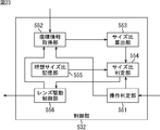
- the image processing apparatus 11 includes an optical system 31, an imager 32, a digital signal processing unit 33, a display unit 34, a control unit 35, a lens driving unit 36, an interface control unit 37, and a user interface 38.
- the optical system 31 is configured as an optical system including a zoom lens and a focus lens (not shown).
- the light incident on the optical system 31 is photoelectrically converted by an imager 32 configured by an image sensor such as a CCD (Charge Coupled Device).
- the electrical signal (analog signal) photoelectrically converted by the imager 32 is converted into image data of a digital signal by an A / D (Analog-to-Digital) converter (not shown) and supplied to the digital signal processor 33.
- the digital signal processing unit 33 performs predetermined signal processing on the digital signal (image data) from the imager 32.
- the digital signal processing unit 33 includes a preprocessing unit 51, a demosaic processing unit 52, a YC generation unit 53, a resolution conversion unit 54, a subject tracking unit 55, and a CODEC 56.
- the preprocessing unit 51 clamps R, G, and B black levels to a predetermined level for image data from the imager 32, and correction processing between R, G, and B color channels.
- the demosaic processing unit 52 performs demosaic processing for complementing the color components of the pixels so that each pixel of the image data has all the R, G, and B color components for the image data preprocessed by the preprocessing unit 51. Apply.
- the YC generation unit 53 generates (separates) a luminance (Y) signal and a color (C) signal from the R, G, and B image data demosaiced by the demosaic processing unit 52.
- the resolution conversion unit 54 performs resolution conversion processing on the image data processed by the YC generation unit 53.
- the subject tracking unit 55 detects a subject in the input image (captured image) corresponding to the image data based on the image data including the luminance signal and the color signal generated by the YC generation unit 53, and performs subject tracking processing for tracking. Execute.
- the detection of the subject is performed assuming that when the user glances at the input image, an object on the input image that is estimated to be noticed by the user, that is, an object that is estimated to be looked at by the user is the subject. Therefore, the subject is not necessarily limited to a person.
- the subject tracking unit 55 supplies the control unit 35 with data about a subject frame representing a region including the subject in the input image obtained as a result of the subject tracking process. Details of the subject tracking unit 55 will be described later with reference to FIG.
- the CODEC 56 encodes the image data generated by the YC generation unit 53 or the resolution conversion unit 54 as necessary, and records the data in a memory (not shown) or decodes the encoded image data.
- the image data decoded by the CODEC 56 or the image data obtained by the resolution conversion unit 54 is supplied to the display unit 34 and displayed.
- the display unit 34 includes, for example, a liquid crystal display, and displays an input image (hereinafter also referred to as a captured image as appropriate) corresponding to the image data supplied from the digital signal processing unit 33 under the control of the control unit 35.
- the control unit 35 controls each unit of the image processing apparatus 11 according to a control signal supplied from the interface control unit 37.
- control unit 35 supplies parameters and the like used for various types of signal processing to the digital signal processing unit 33, acquires data obtained as a result of various types of signal processing from the digital signal processing unit 33, This is supplied to the interface control unit 37.
- control unit 35 supplies a control signal for driving the zoom lens and the focus lens constituting the optical system 31 and adjusting the diaphragm and the like to the lens driving unit 36. Further, the control unit 35 also controls imaging of an input image by the imager 32.
- the user interface 38 is input from an input device such as a button, lever, switch, or microphone that is operated when the user inputs an instruction to the image processing apparatus 11, or an output device such as a lamp or speaker that presents information to the user. Composed.
- an input device such as a button, lever, switch, or microphone that is operated when the user inputs an instruction to the image processing apparatus 11, or an output device such as a lamp or speaker that presents information to the user. Composed.
- the user interface 38 supplies a control signal corresponding to the operation to the control unit 35 via the interface control unit 37.
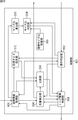
- 2 includes a subject map generation unit 71, a subject candidate region rectangularization unit 72, a subject region selection unit 73, and a weight coefficient calculation unit 74.
- the subject map generation unit 71 generates a feature amount map indicating a feature amount in a predetermined region of a predetermined frame of the input image for each feature such as luminance and color of the input image, and supplies the feature amount map to the weight coefficient calculation unit 74. In addition, the subject map generation unit 71 generates a subject map indicating the likelihood of the subject area in the input image based on the generated feature amount map and the weighting factor for each feature amount supplied from the weighting factor calculation unit 74. .
- the subject map generation unit 71 generates a subject map by weighting and adding information (feature amount) of each region of the feature amount map for each feature for each region at the same position.
- the subject map generation unit 71 supplies the generated subject map to the subject candidate area rectangularization unit 72.
- a region having a larger amount of information that is, a region on the input image corresponding to a region having a larger feature amount is a region having a higher possibility of including a subject.
- a region including a subject in the input image can be specified.
- the subject candidate area rectangularizing unit 72 obtains a candidate area in the subject map from the subject map generating unit 71, that is, a rectangular area including a large amount of information in the subject map, and obtains the coordinates of the rectangular area.
- the coordinate information to be expressed is supplied to the subject area selection unit 73.
- the subject candidate area rectangularization unit 72 calculates information related to the rectangular area represented by the coordinate information on the subject map (hereinafter referred to as area information) and supplies the information to the subject area selection unit 73 in association with the coordinate information.
- the subject area selection unit 73 selects a subject area, which is a rectangular area including a subject to be noticed, as a tracking target from the rectangular areas based on the area information from the subject candidate area rectangularization unit 72, and The coordinate information of the subject area is supplied to the control unit 35 (FIG. 1) and the weight coefficient calculation unit 74.
- the weighting coefficient calculation unit 74 is the feature amount of the next frame corresponding to a relatively large feature amount among the feature amounts in the region corresponding to the subject region on each feature amount map of the predetermined frame from the subject map generation unit 71.
- a weighting factor for weighting the map is calculated and supplied to the subject map generation unit 71.
- the subject tracking unit 55 can obtain a subject frame representing a subject region for each frame of the input image.
- 3 includes a feature amount map generation unit 111, a band feature amount map generation unit 112, a band feature amount map synthesis unit 113, and a synthesis feature amount map synthesis unit 114.
- the feature amount map generation unit 111 generates a feature amount map indicating information (feature amount) related to features such as luminance and color from a predetermined frame of the input image for each feature amount, and supplies the feature amount map to the band feature amount map generation unit 112.
- the band feature amount map generation unit 112 extracts a feature amount of a predetermined band component from the feature amount in each feature amount map from the feature amount map generation unit 111 a predetermined number of times, and indicates the extracted feature amount A feature amount map is generated and supplied to the weighting factor calculation unit 74 and the band feature amount map synthesis unit 113.
- the band feature quantity map synthesis unit 113 synthesizes the band feature quantity map from the band feature quantity map generation unit 112 for each feature quantity based on the weighting coefficient from the weighting coefficient calculation unit 74, thereby generating a synthesized feature quantity map. Generated and supplied to the weighting factor calculation unit 74 and the combined feature amount map combining unit 114.
- the composite feature amount map combining unit 114 generates a subject map by combining the combined feature amount map from the band feature amount map combining unit 113 based on the weighting factor from the weighting factor calculating unit 74, and generates a subject candidate area. It supplies to the rectangularization part 72 (FIG. 2).
- band feature amount map and composite feature amount map are also simply referred to as a feature amount map.
- a binarization processing unit 131 includes a binarization processing unit 131, a labeling processing unit 132, a rectangular region coordinate calculation unit 133, and a region information calculation unit 134.
- the binarization processing unit 131 binarizes information corresponding to each pixel of the input image in the subject map supplied from the subject map generation unit 71 to either 0 or 1 based on a predetermined threshold. To the labeling processing unit 132.
- information corresponding to each pixel of the input image is also simply referred to as a pixel.
- the labeling processing unit 132 performs labeling on a region adjacent to a pixel having a value of 1 (hereinafter referred to as a connected region), and rectangular region coordinates. It supplies to the calculation part 133.
- the rectangular area coordinate calculation unit 133 calculates the coordinates of the rectangular area including (surrounding) the connected area in the object map labeled with the connected area from the labeling processing unit 132, and uses the coordinate information representing the coordinates as the object map. At the same time, it is supplied to the area information calculation unit 134.
- the area information calculation unit 134 calculates area information that is information related to the rectangular area represented by the coordinate information on the object map from the rectangular area coordinate calculation unit 133, and associates with the coordinate information to the object area selection unit 73 (FIG. To 1).
- 5 includes a region information comparison unit 151 and a subject region determination unit 152.
- the region information comparison unit 151 compares the region information of each rectangular region from the subject candidate region rectangularization unit 72 with the region information of the subject region of the previous frame stored in the region information storage unit 153, and the comparison result Is supplied to the subject region determination unit 252.
- the subject region determination unit 152 Based on the comparison result from the region information comparison unit 151, the subject region determination unit 152 sets the rectangular region represented by the coordinate information associated with the region information closest to the region information of the subject region one frame before the subject. This is an area.
- the subject area determination unit 152 supplies the coordinate information of the determined subject area to the control unit 35 (FIG. 1) and the weighting factor calculation unit 74 (FIG. 2), and the area information of the subject area is stored in the area information storage unit 153. Supply.
- the region information storage unit 153 stores the region information of the subject region from the subject region determination unit 152.
- the area information of the subject area stored in the area information storage unit 153 is read by the area information comparison unit 151 one frame later.
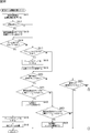
- FIG. 6 is a flowchart for explaining subject tracking processing of the image processing apparatus 11.
- the operation mode of the image processing apparatus 11 is changed to the subject tracking process mode in which the subject tracking process is executed, and is displayed on the display unit 34. This is started when a predetermined area of the subject as a tracking target is selected by the user in the input image.
- step S11 the subject map generation unit 71 of the subject tracking unit 55 performs a subject map generation process, generates a subject map, and supplies the subject map to the subject candidate area rectangularization unit 72.
- FIG. 7 is a flowchart for describing subject map generation processing
- FIG. 8 is a diagram illustrating a specific example of subject map generation processing.
- step S31 of the flowchart of FIG. 7 the feature amount map generation unit 111 of the subject map generation unit 71 generates a feature amount map for features (for each feature amount) such as luminance and color from a predetermined frame of the input image, and the bandwidth This is supplied to the feature amount map generation unit 112.
- a luminance information map F 1 indicating information regarding luminance
- color information maps F 2 to F K indicating information regarding color
- edge information indicating information regarding edges.
- M types of feature amount maps of maps F (K + 1) to F M are generated.
- the luminance information map F 1 the luminance component (luminance signal) Y obtained from each pixel of the input image becomes the information corresponding to each pixel of the input image
- the color information map F 2 to F K the input image Color components (color signals) R, G, and B obtained from each pixel become information corresponding to each pixel of the input image.
- the edge information map F (K + 1) to F M for example, 0 degrees of each pixel of the input image, 45 degrees, 90 degrees, and 135 degrees in the direction of the edge strength corresponding to each pixel of the input image Information.
- the feature amount map as described above may be a luminance information map F 1 information an average value of each component of R, G, B pixel (features), the color difference components Cr, and Cb, Lab color
- the a * coordinate component and b * coordinate component in the space may be used as the information of the color information maps F 2 to F K.
- step S32 the band feature quantity map generation unit 112 extracts a feature quantity of a predetermined band component from the feature quantities in each feature quantity map N times, and generates a band feature quantity map indicating each extracted feature quantity. And supplied to the weight coefficient calculation unit 74 and the band feature amount map synthesis unit 113.
- the luminance information of a predetermined band 1 to N is extracted from the luminance information in the luminance information map F 1 , and the band luminance information map R indicating the luminance information of each band. 11 to R 1N are generated. Further, color information of predetermined bands 1 to N is extracted from the color information in the color information maps F 2 to F K , and band color information maps R 21 to R 2N ,..., R indicating the color information of each band. K1 to R KN are generated.
- the edge information in the edge information map F (K + 1) to F M, the edge information in a predetermined band 1 to band N are extracted, the map band edge information indicating the bandwidth respective edge information R (K + 1) 1 to R (K + 1) N 1 ,..., R M1 to R MN are generated.
- the band feature amount map generation unit 112 generates (M ⁇ N) types of band feature amount maps.
- the band feature quantity map generation unit 112 uses each feature quantity map to generate a plurality of feature quantity maps having different resolutions, and sets these feature quantity maps as pyramid images of the feature quantities. For example, it is assumed that pyramid images of eight resolution layers from level L1 to level L8 are generated, the pyramid image of level L1 has the highest resolution, and the resolution of the pyramid image sequentially decreases from level L1 to level L8. .
- the feature map generated by the feature map generation unit 111 is a pyramid image of level L1.
- the pyramid image of level Li (where 1 ⁇ i ⁇ 7)
- the pyramid image at the level L (i + 1) is an image of half the length and breadth (discarded if not divisible) with respect to the pyramid image at the level Li.
- the band feature amount map generation unit 112 selects two pyramid images having different hierarchies from among a plurality of pyramid images, obtains a difference between the selected pyramid images, and generates N difference images of each feature amount. . Since the pyramid images in each layer have different sizes (number of pixels), the smaller pyramid image is up-converted according to the larger pyramid image when the difference image is generated.
- the band feature map generation unit 112 includes the level L6 and level L3, the level L7 and level L3, the level L7 and level L4, the level L8 and level L4, and the level L8 and
- the difference of the pyramid image of the combination of each hierarchy of level L5 is calculated
- difference images of a total of five feature amounts are obtained.
- the pyramid image of level L6 is up-converted according to the size of the pyramid image of level L3.
- the pixel value of one pixel of the pyramid image at level L6 before up-conversion is the pixel value of several pixels adjacent to each other in the pyramid image at level L6 after up-conversion corresponding to that pixel.
- the difference between the pixel value of the pixel of the level L6 pyramid image and the pixel value of the pixel of the level L3 pyramid image at the same position as the pixel is obtained, and the difference is set as the pixel value of the pixel of the difference image.
- the width of the band extracted from the feature map is determined by the combination of each layer of the pyramid image when obtaining the difference image, but this combination is arbitrarily determined.
- the extraction of the feature amount of the predetermined band component is not limited to the above-described method using the difference image, and other methods may be used.
- step S33 the band feature amount map synthesis unit 113, a band feature quantity map from the band feature amount map generating unit 112, based on the weight coefficient group W R from the weight coefficient calculation unit 74 Combining for each feature.
- the band feature amount map combining unit 113 supplies the combined band feature amount map (combined feature amount map) to the weighting coefficient calculating unit 74 and the combined feature amount map combining unit 114.
- the band luminance information maps R 11 to R 1N are weighted by weighting factors w 11 to w 1N that are weights for each band luminance information map from the weighting factor calculating unit 74. It is added, the synthetic characteristic amount map C 1 is obtained. Further, the map-band color information R 21 to R 2N, ..., R K1 to R KN is the weighting factor w 21 through w 2N is the weight of the band color information for each map from the weight coefficient calculation unit 74, ..., w K1 to summed weighted by w KN, synthetic feature amount maps C 2 to C K is determined.
- the band edge information maps R (K + 1) 1 to R (K + 1) N ,..., R M1 to R MN are weight coefficients w (K + 1) 1 that are weights for each band edge information map from the weight coefficient calculation unit 74.
- w (K + 1) N 1 ,..., W M1 to w MN are weighted and added to obtain composite feature amount maps C K + 1 to C M.
- the band feature quantity map synthesis unit 113 generates M types of synthesized feature quantity maps.
- weight coefficient group W R the weight coefficients of the weight coefficient group W R has a value of 0 to 1.
- each weighting factor of the weighting coefficient group W R is all 1, band feature amount maps are added without weighting.
- step S34 the synthetic characteristic amount map synthesis unit 114, the synthetic characteristic quantity map from the band feature amount map synthesis unit 113, by synthesizing based on the weight coefficient group W C from the weight coefficient calculation unit 74, the subject map Is generated and supplied to the subject candidate area rectangularization unit 72.
- the combined feature amount maps C 1 to C M use weighting factors w 1 to w M that are weights for each band luminance information map from the weighting factor calculation unit 74.
- the subject map 201 is obtained by multiplying the pixel value of the map obtained as a result of the linear combination by the subject weight, which is a weight obtained in advance, and normalizing it.
- weight coefficient group W C the weight coefficients of the weight coefficient group W C has a value of 0 to 1.
- each weighting factor of the weighting coefficient group W C is all 1, synthesized characteristic quantity map is a linear combination without weights.
- the weight coefficient for each composite feature map is set to the pixel value at the same position (pixel) as the target position of each composite feature map. And the sum of the pixel values multiplied by the weighting coefficient is used as the pixel value at the target position. Further, the pixel value at each position of the subject map obtained in this way is multiplied by a subject weight obtained in advance with respect to the subject map and normalized to obtain a final subject map. For example, the normalization is performed so that the pixel value of each pixel of the subject map becomes a value between 0 and 255.
- the subject map generation unit 71 generates the subject map by generating the band feature amount map and the combined feature amount map from the feature amount map.
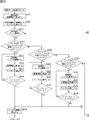
- step S ⁇ b> 12 the subject candidate region rectangularization unit 72 performs subject candidate region rectangularization processing, and in the subject map from the subject map generation unit 71, a rectangular region that includes regions that are subject candidates. Ask for.
- FIG. 9 is a flowchart for describing the subject candidate area rectangularization process
- FIG. 10 is a diagram illustrating a specific example of the subject candidate area rectangularization process.
- step S51 of the flowchart of FIG. 9 the binarization processing unit 131 of the subject candidate area rectangularization unit 72 sets the information in the subject map supplied from the subject map generation unit 71 to 0 or 1 based on a predetermined threshold. It binarizes to either value and supplies it to the labeling processing unit 132.
- the binarization processing unit 131 performs, for example, a pixel value of each pixel of the subject map 201 that is a value between 0 and 255 shown first from the top in FIG. A pixel value having a value smaller than the threshold 127 is set to 0, and a pixel value having a value greater than 127 is set to 1. As a result, a binarized map 202 as shown second from the top in FIG. 10 is obtained. In the binarization map 202 shown in FIG. 10, a portion (pixel) indicated by white has a pixel value of 1, and a portion (pixel) indicated by black has a pixel value of 0. Although the threshold value is 127 here, other values may be used.
- step S52 the labeling processing unit 132 obtains a pixel having a pixel value of 1 obtained from the binarization processing unit 131 by a morphological operation or the like in the binarization map 202 (binarized subject map).
- the adjacent connected areas are labeled and supplied to the rectangular area coordinate calculation unit 133.
- the connected area 211 is labeled with the label “1”, and the connected area 212 is labeled “2”. ".
- step S ⁇ b> 53 the rectangular area coordinate calculation unit 133 calculates the coordinates of the rectangular area including (enclosed) the connected area in the binarized map 202 from the labeling processing unit 132, and converts the coordinate information representing the coordinates into binary. It is supplied to the region information calculation unit 134 together with the conversion map 202.
- a rectangular frame (circumscribed frame) 221 that surrounds the connected region 211 labeled with the label “1” from the outside is detected. Then, for example, the coordinates of the vertices of the upper left corner and the lower right corner of the rectangular frame are obtained. Further, a rectangular frame 222 surrounding the connection area 212 labeled with the label “2” is detected from the outside, and the coordinates of the vertexes of the rectangular frame, for example, the upper left and lower right in the figure are obtained.
- the region information calculation unit 134 is a region for a rectangular region surrounded by a rectangular frame on the subject map based on the coordinate information from the rectangular region coordinate calculation unit 133 and the subject map from the subject map generation unit 71. Calculate information.
- the area information calculation unit 134 represents the rectangular frame size and center position coordinates based on the coordinate information from the rectangular area coordinate calculation unit 133 representing the rectangular frames 221 and 222 in the binarization map 202. Is calculated as region information for the rectangular region.
- the area information calculation unit 134 supplies the calculated area information to the subject area selection unit 73 in association with the coordinate information from the rectangular area coordinate calculation unit 133.
- the subject candidate region rectangularization unit 72 determines the characteristics of the rectangular frame surrounding each region that is a candidate for the subject to be noted in the subject map and the region surrounded by the rectangular frame on the subject map. Find the region information to represent.
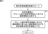
- the subject region selection unit 73 performs subject region selection processing, and uses the subject region, which is a rectangular region including the subject to be noted, as region information from the subject region selection unit 73. Based on this, select from the rectangular area.
- step S ⁇ b> 71 the region information comparison unit 151 compares the region information of each rectangular region from the subject candidate region rectangularization unit 72 with the region information of the subject region of the previous frame stored in the region information storage unit 153. Then, the comparison result is supplied to the subject region determination unit 152.
- the region information comparison unit 151 stores the size of the rectangular frame surrounding each rectangular region on the subject map from the subject candidate region rectangularization unit 72 and the region information storage unit 153. The size of the rectangular frame (subject frame) surrounding the subject area one frame before is compared. Further, for example, the region information comparison unit 151 is stored in the region information storage unit 153 and the coordinates of the center position of a rectangular frame surrounding each rectangular region on the subject map from the subject candidate region rectangularization unit 72. The coordinates of the center position of a rectangular frame (subject frame) surrounding the subject area one frame before are compared.
- the subject area determination unit 152 based on the comparison result from the area information comparison unit 151, has the rectangular frame closest to the coordinates of the size or center position of the rectangular frame (subject frame) surrounding the subject area one frame before.
- a rectangular area having a size or a center position is defined as a subject area.
- the subject area determination unit 152 supplies the coordinate information of the determined subject area to the control unit 35 and the weighting coefficient calculation unit 74, and the area information storage unit 153 stores the area information of the subject area (the size or center position of the subject frame). To supply.
- the region information storage unit 153 does not store the region information of the subject region one frame before, so the predetermined region of the subject selected by the user at the start of the subject tracking process
- a rectangular area including (hereinafter referred to as an initial selection area) is a subject area.
- the subject region selection unit 73 selects a subject region of a subject to be noted from rectangular regions that are candidate subjects.
- the weight coefficient calculation unit 74 includes a band feature amount map and a combined feature amount map from the subject map generation unit 71, and coordinate information representing the subject region from the subject region selection unit 73. Based on the above, the weight coefficient groups W R and W C shown in FIG. 8 are calculated.
- weight coefficient group W R as shown on the upper side of FIG. 13 is calculated.
- Each coefficient in the weight coefficient group W R of FIG. 13 corresponds to each of the weight coefficients w 11 to w MN shown in FIG.
- Max [a,..., Z] represents the maximum value among the values a to z.
- each coefficient of the first row from the top in the weight coefficient group W R of FIG. 13, shown in FIG. 8, "band 1" is the feature quantity for each of the band feature amount maps R 11 to R M1 of It shows the weighting factor w 11 to w M1.
- the weighting factors w 11 to w M1 are the maximum values of the subject area feature amount sums r 11 to r M1 for the band feature amount maps R 11 to R M1, respectively.
- the weighting factors w 1N to w MN are shown.
- the weight coefficients w 1N to w MN are denominators that are the maximum values of the subject area feature amount sums r 1N to r MN for the band feature amount maps R 1N to R MN, respectively.
- the other band feature amount maps are weighted according to the subject region feature amount sum.
- the sum of the feature amounts (information amounts) in the rectangular area corresponding to the rectangular frame 221 representing the subject area on the predetermined composite feature quantity map C m (1 ⁇ m ⁇ M) is the subject area feature amount sum cm.
- a weight coefficient group W C as shown in the lower side of FIG. 13 is calculated.
- Each coefficient in the weight coefficient group W C of FIG. 13 corresponds to each of the weighting coefficients w 1 to w M shown in FIG.
- each coefficient in the weight coefficient group W C in FIG. 13 indicates the weight coefficients w 1 to w M for the combined feature amount maps C 1 to C M for each feature amount shown in FIG.
- the weighting factors w 1 to w M are the maximum values of the subject area feature amount sums c 1 to c M for the combined feature amount maps C 1 to C M as the denominators.
- are coefficients that are subject area feature amount sums c 1 to c M for each of the combined feature amount maps C 1 to C M and take values of 0 to 1.
- the maximum value 1 in the synthesis feature amount map feature quantity subject region feature sum is maximum
- the other band feature quantity maps are weighted according to the subject area feature quantity sum.
- Weight coefficient calculation unit 74 the weight coefficient group W R calculated, and supplies the band feature amount map synthesis section 113 of the subject map generation unit 71, the weight coefficient group W C, synthesized characteristic quantity of the subject map generation unit 71 This is supplied to the map composition unit 114.
- the subject tracking process for the next frame is executed after step S14, and this process is repeated for each frame.
- the following is performed according to the relative size of the feature amount of the region corresponding to the subject region selected in the frame.
- a weighting factor for the feature amount map for each feature amount of the frame is determined. Therefore, even when the feature amount varies between frames, a feature map of the feature amount that best represents the subject among the plurality of feature amounts is generated with the most weighted subject map. Even in an environment where the state of the subject fluctuates, the subject can be tracked more stably.
- the subject area is determined so as to include the entire subject, the subject can be tracked more stably even in an environment where the state of a part of the subject area fluctuates.
- the subject region including the entire subject can be identified, so that the detection accuracy can be improved, and consequently the tracking result can be applied to various applications.
- conventional subject tracking methods include, for example, a method for detecting and tracking a human by registering an entire image of a human in a dictionary by learning, but a non-human subject that is not registered in the dictionary can be detected. It cannot be tracked. Furthermore, since the amount of information (images) registered in the dictionary is enormous, the apparatus scale becomes large.
- the luminance component, the color component, and the edge direction are used as the feature amount.
- the present invention is not limited to this, and for example, motion information or the like may be added.
- the feature amount used is preferably a complementary relationship such as a luminance component and a color component, and may be appropriately selected.
- M ⁇ (N + 1) types of weighting coefficients are calculated corresponding to M ⁇ (N + 1) types of feature amount maps.
- weighting factors corresponding to some feature amount maps are calculated. Is appropriately calculated, the amount of calculation in the image processing apparatus 11 can be suppressed. For example, only the weighting factors w 1 to w M corresponding to the M types of feature amount maps of the combined feature amount maps C 1 to C M may be calculated.
- the area information calculation unit 134 calculates the size of the rectangular frame and the coordinates of the center position as the area information of the rectangular area.
- the integrated value or peak value (Maximum value) may be calculated.
- a rectangular region having an integral value or peak value of the pixel value in the region closest to the integrated value or peak value of the pixel value in the subject region one frame before is the subject. It is considered as an area.
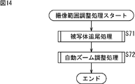
- the image processing apparatus 11 performs an imaging range adjustment process for capturing an image of the tracked subject while keeping the size of the subject in the imaging range constant. Can be executed.
- Imaging range adjustment processing For example, when the user operates the user interface 38 as a button, the operation mode of the image processing apparatus 11 is changed to the imaging mode for imaging the subject, and the input displayed on the display unit 34. This is started when a predetermined area of a subject as an imaging target is selected by the user in the image (captured image).
- step S71 the subject tracking unit 55 executes the subject tracking process described in the flowchart of FIG. 6 and supplies the coordinate information of the subject region to the control unit 35.
- step S ⁇ b> 72 the control unit 35 drives the zoom lens included in the optical system 31 to the lens driving unit 36 by controlling the lens driving unit 36 based on the coordinate information of the subject area from the subject tracking unit 55.
- the automatic zoom adjustment process is executed.
- the size of the subject in the imaging range can be kept constant even if the distance to the subject changes.
- control unit 35 executes the automatic zoom adjustment processing in step S72 of the flowchart of FIG. 14 will be described with reference to FIG.
- the 15 includes a coordinate information acquisition unit 311, a target size setting unit 312, an operation determination unit 313, a position detection unit 314, a comparison unit 315, and a lens drive control unit 316.
- the coordinate information acquisition unit 311 acquires the coordinate information of the subject area supplied for each frame of the input image from the subject tracking unit 55 and supplies the coordinate information to the target size setting unit 312, the position detection unit 314, and the comparison unit 315. To do.
- the coordinate information acquisition unit 311 acquires coordinate information from the subject tracking unit 55
- the coordinate information acquisition unit 311 supplies information indicating that the coordinate information has been acquired to the operation determination unit 313.
- the target size setting unit 312 Based on the coordinate information of the subject area from the coordinate information acquisition unit 311, the target size setting unit 312 keeps the size of the subject area represented by the coordinate information for a predetermined frame and the size of the subject in the imaging range constant. Set as the target size that is the target to keep. That is, the control unit 35 causes the lens driving unit 36 to drive the zoom lens so that the size of the subject area always approaches the target size.
- the target size setting unit 312 supplies the set target size to the comparison unit 315.
- the operation determination unit 313 serves as the user interface 38 based on the control signal from the user interface control unit 37. It is determined whether or not the zoom button (or zoom lever) is operated.
- the operation determination unit 313 supplies information indicating the determination result to the target size setting unit 312, the position detection unit 314, and the lens drive control unit 316.
- the position detection unit 314 detects the position of the subject in the imaging range based on the coordinate information of the subject area from the coordinate information acquisition unit 311, and uses information corresponding to the position as a comparison unit 315, a lens drive control unit 316, And it supplies to the display part 34 (FIG. 1).
- the comparison unit 315 receives the size of the subject area represented by the coordinate information from the coordinate information acquisition unit 311 and the target size setting unit 312. Compare with target size.
- the comparison unit 315 supplies information representing the comparison result to the lens drive control unit 316.
- the lens drive control unit 316 controls the lens drive unit 36 based on the information indicating the determination result from the operation determination unit 313 and the information indicating the comparison result from the comparison unit 315, and the optical system 31 (FIG. 1). ) To drive the zoom lens.
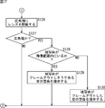
- step S111 the coordinate information acquisition unit 311 acquires the coordinate information of the subject area from the subject tracking unit 55 and supplies the coordinate information to the target size setting unit 312.
- step S112 the coordinate information acquisition unit 311 determines whether or not the operation is an initial operation, that is, the coordinate information acquired in step S111 is the coordinates of the subject area for the first frame after the imaging range adjustment process (FIG. 14) is started. It is determined whether it is information.
- step S112 If it is determined in step S112 that the operation is an initial operation, the coordinate information acquisition unit 311 obtains information indicating that the coordinate information for the first frame has been acquired after the imaging range adjustment processing has been started, as the target size setting unit 312. And it supplies to the operation determination part 313, and a process progresses to step S113.
- step S ⁇ b> 113 when the coordinate information of the subject area for the first frame is supplied from the coordinate information acquisition unit 311, the target size setting unit 312 is the size of the subject area that is a rectangular area represented by the coordinate information. Is set as the target size. Specifically, the target size setting unit 312 sets the subject area width Hw (or height Hh) for the first frame as the target width Hw_target (or target height Hh_target). The target size setting unit 312 supplies the set target size to the comparison unit 315, and the process proceeds to step S114.
- step S112 determines whether the operation is not an initial operation, that is, the coordinate information acquired in step S111 is the second and subsequent coordinates information after the coordinate information acquisition unit 311 starts the imaging range adjustment process (FIG. 14). If it is coordinate information of the subject area for the frame, the coordinate information acquisition unit 311 supplies information indicating that the coordinate information has been acquired to the operation determination unit 313, and the process proceeds to step S114.
- step S ⁇ b> 114 when the information indicating that the coordinate information is acquired from the subject tracking unit 55 is supplied from the coordinate information acquisition unit 311, the operation determination unit 313 is based on a control signal from the user interface control unit 37. It is determined whether or not the zoom operation is performed.
- step S ⁇ b> 114 when it is determined that the zoom operation by the user is performed, the operation determination unit 313 supplies a control signal representing the zoom operation content from the user interface control unit 37 to the lens drive control unit 316. The process proceeds to step S115.
- step S115 the operation determination unit 313 turns on the manual flag held inside.
- the manual flag is a flag that indicates whether or not the user has performed a zoom operation in the automatic zoom adjustment process of the imaging range adjustment process for the previous frame while the imaging range adjustment process is performed for each frame. It is. That is, in the automatic zoom adjustment process for the previous frame, the manual flag is ON if the zoom operation is performed by the user, and the manual flag is OFF if the zoom operation is not performed. Note that the manual flag is OFF immediately after the imaging range adjustment process (automatic zoom adjustment process) is started.
- step S ⁇ b> 116 the lens drive control unit 316 controls the lens drive unit 36 according to the zoom operation (wide angle instruction or telephoto instruction) by the user, which is represented by the control signal from the operation determination unit 313, and the optical system 31. Is driven by a distance d1.
- the distance d1 is a distance that allows the lens driving unit 36 to move the zoom lens while subject tracking processing for one frame is executed.
- the user can adjust the imaging range (view angle) according to his / her preference regardless of whether or not the subject is being tracked in the imaging range.
- step S117 the operation determination unit 313 determines whether or not the manual flag held inside is ON.
- step S117 If it is determined in step S117 that the manual flag is ON, that is, if the user has performed a zoom operation in the automatic zoom adjustment process for the previous frame, the process proceeds to step S118.
- step S118 the operation determination unit 313 turns off the manual flag held therein, and supplies information indicating that the manual flag is turned off to the target size setting unit 312 and the position detection unit 314.
- step S119 based on the information from the operation determination unit 313, the target size setting unit 312 sets the size of the subject area represented by the coordinate information of the subject area for the current frame from the coordinate information acquisition unit 311. Based on this, the target size is updated and supplied to the comparison unit 315.
- the size of the subject in the imaging range (view angle) adjusted by the user that is, the size of the subject region is newly set as the target size.
- step S117 determines whether the manual flag is ON, that is, if the zoom operation by the user is not performed in the automatic zoom adjustment process for the previous frame.
- the operation determination unit 313 performs manual operation. Information indicating that the flag is OFF is supplied to the position detection unit 314.
- step S120 when information indicating that the manual flag is OFF (or turned OFF) is supplied from the operation determination unit 313, the position detection unit 314 receives the coordinates of the subject area from the coordinate information acquisition unit 311. Based on the information, the position of the subject in the imaging range is detected. Then, based on the detected position, the position detection unit 314 determines whether or not the subject is in the area A in the imaging range shown in FIG.
- FIG. 18 is a diagram illustrating an imaging range in which a subject is imaged in a captured image displayed on the display unit 34.
- the subject is surrounded by a subject frame H representing the subject region.
- region B are shown with the broken line.
- Area A is an area that is set so as to include the central portion of the imaging range, and it is desirable that the subject be inside of the area at the time of imaging.
- Area B is an area that is set as an outer end area of the imaging range, and may be out of the imaging range (out of frame) if the subject is outside of the imaging range during imaging.
- step S120 the position detection unit 314 determines whether or not the subject is in a region desired for imaging within the imaging range. Specifically, the position detection unit 314 determines whether or not the center coordinates (or any one of the coordinates of the four vertices) of the subject frame H representing the subject region exist in the region A.
- step S120 If it is determined in step S120 that the subject is in the region A, the position detection unit 314 supplies information indicating that the subject is in the region A to the comparison unit 315, and the process proceeds to step S121.
- step S ⁇ b> 121 when the information indicating that the subject is in the region A is supplied from the position detection unit 314, the comparison unit 315 receives the size of the subject region represented by the coordinate information from the coordinate information acquisition unit 311, and The target size from the target size setting unit 312 is compared.
- the comparison unit 315 sets the target width Hw_target (or target height Hh_target) of the subject frame H in FIG.
- the width Hw (or height Hh) of the subject area is compared as the size of the subject area for the current frame.
- the comparison unit 315 determines whether or not the size of the subject area is larger than the target size, specifically, the width Hw (or height Hh) of the subject area is set to the target width Hw_target (or target height Hh_target). It is determined whether or not it is larger than the value obtained by adding the values.
- step S121 as shown in FIG. 19, when it is determined that the size of the subject region is larger than the target size, the comparison unit 315 gives information that the size of the subject region is larger than the target size to the lens drive control unit 316. The process proceeds to step S122.
- step S122 the lens drive control unit 316 controls the lens drive unit 36 based on the information from the comparison unit 315 to drive the zoom lens of the optical system 31 by the distance d1 to the wide angle side.
- zooming out is performed so that the size of the subject approaches the target size.
- step S121 determines whether the size of the subject area is larger than the target size. If it is determined in step S121 that the size of the subject area is not larger than the target size, the process proceeds to step S123.
- step S123 the comparison unit 315 determines whether or not the size of the subject area is smaller than the target size, specifically, the width Hw (or height Hh) of the subject area is the target width Hw_target (or target height Hh_target). It is determined whether or not it is smaller than a value obtained by subtracting a predetermined value from.
- step S123 as shown in FIG. 20, when it is determined that the size of the subject area is smaller than the target size, the comparison unit 315 gives information that the size of the subject area is smaller than the target size to the lens drive control unit 316. The process proceeds to step S124.
- step S124 the lens drive control unit 316 controls the lens drive unit 36 based on the information from the comparison unit 315, and drives the zoom lens of the optical system 31 to the telephoto side by the distance d1.
- the zoom-in is performed so that the size of the subject approaches the target size.
- step S123 if it is determined in step S123 that the size of the subject area is not smaller than the target size, that is, if the size of the subject area is the same as or substantially the same as the target size, the comparison unit 315 does nothing, and accordingly No information is supplied to the lens drive control unit 316.
- step S120 when it is determined in step S120 that the subject is not in the region A, the process proceeds to step S125, and the position detection unit 314 determines whether or not the subject is in the region B. Specifically, the position detection unit 314 determines whether or not the center coordinates (or all coordinates of the four vertices) of the subject frame H representing the subject region exist inside the region B.
- step S125 When it is determined in step S125 that the subject is in the area B, the position detection unit 314 does nothing, and therefore no information is supplied to the lens drive control unit 316.
- step S125 if it is determined in step S125 that the subject is not in the region B, the position detection unit 314 supplies information indicating that the subject is not in the region B to the lens drive control unit 316, and the process proceeds to step S126. move on.
- the lens drive control unit 316 controls the lens drive unit 36 based on the information from the position detection unit 314, and drives the zoom lens of the optical system 31 by the distance d2 to the wide angle side.
- the distance d2 is a distance greater than the distance d1, and is a distance that the lens driving unit 36 can move the zoom lens while subject tracking processing for one frame is executed.
- step S127 the lens drive control unit 316 determines whether or not the lens position of the zoom lens is at the wide angle end as a result of the lens drive unit 36 driving the zoom lens to the wide angle side by the distance d2.
- step S127 When it is determined in step S127 that the lens position of the zoom lens is not at the wide angle end, the lens drive control unit 316 does nothing.
- step S127 if it is determined in step S127 that the lens position of the zoom lens is at the wide angle end, the lens drive control unit 316 supplies information indicating that the lens position of the zoom lens is at the wide angle end to the position detection unit 314. The process proceeds to step S128.
- step S1208 when information is supplied from the lens drive control unit 316, the position detection unit 314 determines whether or not the subject is within the imaging range. Specifically, the position detection unit 314 determines whether or not the center coordinate (or any one of the coordinates of the four vertices) of the subject frame H representing the subject region is within the imaging range and outside the region B. Determine whether.
- step S128 When it is determined in step S128 that the subject is within the imaging range, the position detection unit 314 supplies information for presenting a warning that the subject is about to be out of frame to the display unit 34, and the processing is performed. The process proceeds to step S129.
- step S129 the display unit 34 presents (displays) a warning that the subject is about to be out of frame based on the information from the position detection unit 314.
- the unit 34 displays an arrow P that urges the user to move the imaging range to the right as shown in the upper right of FIG.
- the user can confirm the warning that the subject is about to be out of frame and pan the image processing apparatus 11 itself so that the subject is not out of frame.
- step S128 if it is determined in step S128 that the subject is not within the imaging range, that is, if the subject is out of frame, the position detection unit 314 provides information for presenting a warning that the subject is out of frame, The data is supplied to the display unit 34, and the process proceeds to step S130.
- step S130 the display unit 34 presents (displays) a warning that the subject is out of frame based on the information from the position detection unit 314.
- the display unit 34 For example, when the center coordinates of the subject frame H representing the subject area completely frame out to the right side of the area B in the captured image (imaging range) displayed on the display unit 34, the display unit 34 The arrow P shown in the upper right is displayed with more emphasis.
- the user can confirm the warning that the subject is out of frame and pan the image processing apparatus 11 itself so that the subject is framed in.
- the zoom lens when the size of the subject area is larger than the target size, the zoom lens is driven to the wide angle side so as to zoom out, and when the size of the subject area is smaller than the target size, the zoom-in is performed.
- the zoom lens can be driven to the telephoto side. Therefore, even when the distance to the subject changes during imaging, the size of the subject in the imaging range can be kept substantially constant without performing a delicate zoom operation.
- the zoom operation is performed by the user, the user's operation is given priority, so that the user can adjust the imaging range to the user's preference. Then, after the zoom operation by the user is completed, the size of the subject area at that time is updated as the target size, so that the target size can be set to the user's favorite size.
- the size of the subject area at the time of the initial operation is set as the target size.
- the target size may be determined in advance by a user operation or the like.
- a warning that the subject is about to be out of frame (or out of frame) is displayed on the display unit 34.
- the speaker serving as the user interface 38 outputs sound or is eccentric.
- a vibration part constituted by a motor with a weight added thereto may be provided so that the vibration part is vibrated.
- a person as a subject is tracked and the size of the person is kept substantially constant in the imaging range, but the subject is not limited to a person. Further, when the subject is a person, a face detector that detects the face of the person can be provided so that the size of the face in the imaging range can be kept substantially constant.
- the automatic zoom adjustment process for keeping the size of the subject in the imaging range substantially constant even when the distance to the subject changes during imaging has been described.
- the size of the subject in the imaging range cannot be set to a desired size. That is, when the subject is a person, the size of the person in the imaging range (so-called shot) includes a full shot that captures the whole body image, a bust shot that captures the upper body, an upshot that captures the face, etc.
- the imaging range cannot be adjusted so as to obtain a shot like this.
- FIG. 22 shows a configuration example of an image processing apparatus that adjusts the imaging range so that the size of the subject in the imaging range becomes a desired size.
- the image processing apparatus 511 in FIG. 22 differs from the image processing apparatus 11 in FIG. 1 in that a digital signal processing unit 33 is newly provided with a face detection unit 531, and a control unit 532 is provided instead of the control unit 35. It is a point.
- the face detection unit 531 is based on the image data including the luminance signal and the color signal generated by the YC generation unit 53, and in the input image displayed by the image data, the face detection unit 551 detects the person as the subject detected by the subject tracking unit 55.
- a face is detected from the subject area, and coordinate information representing the face area (hereinafter referred to as a face area) is supplied to the control unit 532.
- the control unit 532 controls the lens driving unit 36 based on the coordinate information of the subject area and the face area from the subject tracking unit 55, thereby causing the lens driving unit 36 to drive the zoom lens included in the optical system 31. .
- control unit 532 in FIG. 22 a functional configuration example of the control unit 532 in FIG. 22 will be described with reference to FIG.
- the 23 includes an operation determination unit 551, a coordinate information acquisition unit 552, a size ratio calculation unit 553, a size ratio determination unit 554, an ideal size ratio storage unit 555, and a lens drive control unit 556.
- the operation determination unit 551 determines whether the zoom button (or zoom lever) as the user interface 38 has been operated based on the control signal from the user interface control unit 37.
- the operation determination unit 551 supplies information indicating the determination result to the coordinate information acquisition unit 552 and the size ratio determination unit 554.
- the coordinate information acquisition unit 552 receives the coordinate information of the subject area and the face area supplied from the subject tracking unit 55 and the face detection unit 531 for each frame in accordance with information from the operation determination unit 551 or the lens drive control unit 556. Is supplied to the size ratio calculation unit 553.
- the size ratio calculation unit 553 calculates the ratio between the size of the subject region and the size of the face region (hereinafter referred to as the size ratio) based on the coordinate information of the subject region and the face region from the coordinate information acquisition unit 552, and the size It supplies to the ratio determination part 554.
- the size ratio determination unit 554 compares the size ratio from the size ratio calculation unit 553 with the ideal size ratio stored in the ideal size ratio storage unit 555, and sends information indicating the comparison result to the lens drive control unit 556. Supply.
- the ideal size ratio storage unit 555 stores an ideal size ratio that is a ratio of an ideal subject area size and a face area size.
- the ideal size ratio is the ratio of the size of the subject area to the size of the face area so that the person as the subject to be imaged becomes an appropriate shot such as full shot, bust shot, and up shot, and is arbitrarily set by the user Is set.
- the ideal size ratio stored in the ideal size ratio storage unit 555 is read by the size ratio determination unit 554 as appropriate.
- the lens drive control unit 556 controls the lens drive unit 36 based on information representing the comparison result from the size ratio determination unit 554, and drives the zoom lens of the optical system 31 (FIG. 22). In addition, the lens drive control unit 556 supplies information indicating that the zoom lens has been driven to the coordinate information acquisition unit 552.
- the face detection unit 531 is a subject detected by subject tracking processing by the subject tracking unit 55 in the input image displayed by the image data based on the image data composed of the luminance signal and the color signal generated by the YC generation unit 53.
- a face is detected from the subject area of the person, and coordinate information representing the face area is supplied to the control unit 532.
- the face of the person being tracked as the subject of interest can be detected in the imaging range.
- step S ⁇ b> 311 the operation determination unit 551 determines whether a zoom operation by the user has been performed based on a control signal from the user interface control unit 37.
- step S311 the process is repeated until the zoom operation is performed by the user.
- the operation determination unit 551 supplies information indicating that the zoom operation has been performed to the coordinate information acquisition unit 552.
- a control signal representing the contents of the zoom operation from the user interface control unit 37 is supplied to the size ratio determination unit 554, and the process proceeds to step S312.
- step S312 when the information indicating that the user has performed a zoom operation is supplied from the operation determination unit 551, the coordinate information acquisition unit 552 receives the coordinate information of the subject area from the subject tracking unit 55 for a predetermined frame. And the coordinate information of the face area from the face detection unit 531 is acquired and supplied to the size ratio calculation unit 553.
- the size ratio calculation unit 553 calculates the size ratio between the size of the subject region and the size of the face region based on the coordinate information of the subject region and the face region from the coordinate information acquisition unit 552. Specifically, the size ratio calculation unit 553 calculates the ratio Fh / Hh (or Fw / Hw) between the height Hh (or width Hw) of the subject area and the height Fh (or width Fw) of the face area, Calculate as size ratio. The size ratio calculation unit 553 supplies the calculated size ratio to the size ratio determination unit 554, and the process proceeds to step S314.
- step S ⁇ b> 3144 when the size ratio is supplied from the size ratio calculation unit 553, the size ratio determination unit 554 receives the size ratio determination unit 554 based on the control signal from the user interface control unit 37 supplied from the operation determination unit 551. It is determined whether the zoom operation is a telephoto zoom operation.
- step S314 If it is determined in step S314 that the zoom operation by the user is a telescopic zoom operation, the process proceeds to step S315.
- step S315 the size ratio determination unit 554 determines whether or not the size ratio is smaller than the ideal size ratio for a full shot from the size ratio calculation unit 553.
- FIG. 27 conceptually shows the relationship between the driving range of the zoom lens and the size of the subject in the input image.
- the zoom lens driving range is shown on the upper side, and in the drawing, the wide-angle end is shown on the left end and the telephoto end is shown on the right end. Also, lens positions LP1 to LP6 are shown between the wide-angle end and the telephoto end.
- images a to c in which a person as a subject is captured are shown on the lower side of FIG.
- the subject is imaged so as to be a full shot, a bust shot, and an up shot.
- the ideal size ratio for a full shot is expressed as Fah / Hah. Is done.
- FIG. 27 shows that this ideal size ratio Fah / Hah is obtained when the lens position of the zoom lens is between positions LP1 and LP2 in the drive range of the zoom lens.
- the ideal size ratio for a bust shot is expressed as Fbh / Hbh.
- FIG. 27 shows that the ideal size ratio Fbh / Hbh is obtained when the lens position of the zoom lens is between positions LP3 to LP4 in the zoom lens drive range.
- the ideal size ratio for an up shot is expressed as Fch / Hch. Is done.
- FIG. 27 shows that this ideal size ratio Fch / Hch is obtained when the lens position of the zoom lens is between positions LP5 to LP6 in the zoom lens drive range.
- step S315 of the flowchart of FIG. 25 it is determined whether or not the size ratio Fh / Hh from the size ratio calculation unit 553 is smaller than the ideal size ratio Fah / Hah for a full shot.
- the size ratio hardly changes even if the subject is captured at a distance or is captured at a distance. That is, in the image a of FIG. 27, the size ratio is substantially the same as Fah / Hah even when the subject is imaged at a greater distance.
- step S315 the size ratio Fh / Hh from the size ratio calculation unit 553 is smaller than the ideal size ratio Fah / Hah for a full shot, and the subject area height Hh is greater than a predetermined threshold value.
- the predetermined threshold is not only a value smaller than the height of the captured image (imaging range), but also a value such that about one face area is placed above and below the subject area in the imaging range. .
- step S315 If it is determined in step S315 that the size ratio is smaller than the ideal size ratio for a full shot, the zoom lens is positioned between the wide-angle end and the lens position LP1 in the zoom lens drive range of FIG.
- the size ratio determination unit 554 supplies information indicating that the zoom lens is to be driven to the telephoto side to the lens drive control unit 556, and the process proceeds to step S316.
- step S316 the lens drive control unit 556 controls the lens drive unit 36 based on the information from the size ratio determination unit 554, and drives the zoom lens of the optical system 31 to the telephoto side by the distance d1.
- the distance d1 is a distance at which the lens driving unit 36 can move the zoom lens while subject tracking processing for one frame is executed.
- the lens drive control unit 556 supplies information indicating that the zoom lens has been driven to the coordinate information acquisition unit 552.
- step S317 when the information indicating that the zoom lens is driven is supplied from the lens drive control unit 556, the coordinate information acquisition unit 552 receives the coordinate information of the subject area from the subject tracking unit 55 for the next frame. And the coordinate information of the face area from the face detection unit 531 is acquired and supplied to the size ratio calculation unit 553.
- step S318 the size ratio calculation unit 553 calculates the size ratio Fh / Hh between the size of the subject region and the size of the face region based on the coordinate information of the subject region and the face region from the coordinate information acquisition unit 552.
- the size ratio calculation unit 553 supplies the calculated size ratio to the size ratio determination unit 554, and the process proceeds to step S319.
- step S319 the size ratio determination unit 554 determines whether the subject has become a full shot, that is, the size ratio Fh / Hh from the size ratio calculation unit 553 is the same as or substantially the same as the ideal size ratio Fah / Hah for a full shot. In addition, it is determined whether or not the height Hh of the subject area is larger than a predetermined threshold value.
- step S319 If it is determined in step S319 that the subject is not a full shot, the size ratio determination is made because the zoom lens position is still between the wide-angle end and the lens position LP1 in the zoom lens drive range of FIG.
- the unit 554 supplies information for instructing driving of the zoom lens to the telephoto side to the lens drive control unit 556, and the process returns to step S316. Thereafter, the processes in steps S316 to S319 are repeated for each frame.
- step S319 If it is determined in step S319 that the subject has become a full shot, since the lens position of the zoom lens has become the lens positions LP1 to LP2 in the drive range of the zoom lens in FIG. 27, the size ratio determination unit 554 Then, information for instructing stop of driving of the zoom lens is supplied to the lens drive control unit 556, and the process proceeds to step S320.
- step S320 the lens drive control unit 556 controls the lens drive unit 36 based on the information from the size ratio determination unit 554, and stops the driving of the zoom lens of the optical system 31.
- step S315 if it is determined in step S315 that the size ratio is not smaller than the ideal size ratio for a full shot, the process proceeds to step S321, and the size ratio determination unit 554 determines that the size ratio is greater than the ideal size ratio for a bust shot. It is determined whether or not it is small. Specifically, it is determined whether or not the size ratio Fh / Hh from the size ratio calculation unit 553 is smaller than the ideal size ratio Fbh / Hbh for a bust shot.
- step S321 If it is determined in step S321 that the size ratio is smaller than the ideal size ratio for a bust shot, the zoom lens position is between lens positions LP1 to LP3 in the zoom lens driving range of FIG.
- the ratio determination unit 554 supplies information indicating that the drive of the zoom lens to the telephoto side is supplied to the lens drive control unit 556, and the process proceeds to step S322.
- steps S322 to S324 Since the processing of steps S322 to S324 is performed in the same manner as the processing of steps S316 to S318 described above, the description thereof is omitted.
- step S325 the size ratio determination unit 554 determines whether the subject has become a bust shot, that is, the size ratio Fh / Hh from the size ratio calculation unit 553 is the same as the ideal size ratio Fbh / Hbh to be a bust shot or It is determined whether or not they are substantially identical.
- step S325 If it is determined in step S325 that the subject is not a bust shot, the size ratio determining unit is in the zoom lens driving range of FIG. 27 because the zoom lens position is still between the lens positions LP1 to LP3. 554 supplies information indicating that the zoom lens is to be driven to the telephoto side to the lens drive control unit 556, and the process returns to step S322. Thereafter, the processes in steps S322 to S325 are repeated for each frame.
- step S325 If it is determined in step S325 that the subject has become a bust shot, the size ratio determining unit 554 determines that the lens position of the zoom lens is in the lens positions LP3 to LP4 in the driving range of the zoom lens in FIG. Then, information for instructing stop of driving of the zoom lens is supplied to the lens drive control unit 556, and the process proceeds to step S320. In step S320, as described above, the driving of the zoom lens is stopped.
- step S321 if it is determined in step S321 that the size ratio is not smaller than the ideal size ratio for the bust shot, the process proceeds to step S326, and the size ratio determination unit 554 determines that the size ratio is greater than the ideal size ratio for the up shot. It is determined whether or not it is small. Specifically, it is determined whether or not the size ratio Fh / Hh from the size ratio calculation unit 553 is smaller than the ideal size ratio Fch / Hch to be an up shot.
- step S326 If it is determined in step S326 that the size ratio is smaller than the ideal size ratio for an up-shot, the zoom lens position is between lens positions LP3 to LP5 in the zoom lens driving range of FIG.
- the ratio determination unit 554 supplies information indicating that the zoom lens is to be driven to the telephoto side to the lens drive control unit 556, and the process proceeds to step S327.
- steps S327 to S329 are performed in the same manner as the processes of steps S316 to S318 and steps S322 to S324 described above, the description thereof is omitted.
- step S330 the size ratio determination unit 554 determines whether the subject has become an up shot, that is, the size ratio Fh / Hh from the size ratio calculation unit 553 is the same as the ideal size ratio Fch / Hch to be an up shot or It is determined whether or not they are substantially the same.
- step S330 If it is determined in step S330 that the subject is not an up-shot, the lens position of the zoom lens is still between the lens positions LP3 to LP5 in the zoom lens drive range of FIG.
- step 554 information indicating that the zoom lens is to be driven toward the telephoto side is supplied to the lens drive control unit 556, and the process returns to step S327. Thereafter, the processes in steps S327 to S329 are repeated for each frame.
- step S330 If it is determined in step S330 that the subject is an up shot, the size ratio determining unit 554 determines that the lens position of the zoom lens is in the lens positions LP5 to LP6 in the driving range of the zoom lens in FIG. Then, information for instructing stop of driving of the zoom lens is supplied to the lens drive control unit 556, and the process proceeds to step S320. In step S320, as described above, the driving of the zoom lens is stopped.
- step S326 if it is determined in step S326 that the size ratio is not smaller than the ideal size ratio for an up shot, that is, in the zoom lens driving range of FIG. 27, the lens position of the zoom lens is on the telephoto side from the lens position LP6. In some cases, nothing is processed. In this case, since the subject is picked up by an up shot or a shot closer (closer) than that, even if the zoom operation on the telephoto side is performed, it is not necessary to zoom in further.
- step S314 if it is determined in step S314 that the zoom operation by the user is not a telescopic zoom operation, that is, if it is determined that the zoom operation by the user is a wide-angle zoom operation, the process proceeds to step S331. move on.
- step S331 the size ratio determination unit 554 determines whether the size ratio is larger than the ideal size ratio for an up shot from the size ratio calculation unit 553. Specifically, it is determined whether or not the size ratio Fh / Hh from the size ratio calculation unit 553 is larger than the ideal size ratio Fch / Hch for an up shot.
- step S331 If it is determined in step S331 that the size ratio is larger than the ideal size ratio for an up shot, the zoom lens is located between the telephoto end and the lens position LP6 in the zoom lens driving range of FIG.
- the size ratio determination unit 554 supplies information indicating that the zoom lens is to be driven to the wide angle side to the lens drive control unit 556, and the process proceeds to step S332.
- step S332 the lens drive control unit 556 controls the lens drive unit 36 based on the information from the size ratio determination unit 554, and drives the zoom lens of the optical system 31 to the wide angle side by the distance d1.
- the lens drive control unit 556 supplies information indicating that the zoom lens has been driven to the coordinate information acquisition unit 552.
- step S333 when the information indicating that the zoom lens is driven is supplied from the lens drive control unit 556, the coordinate information acquisition unit 552 receives the coordinate information of the subject area from the subject tracking unit 55 for the next frame. And the coordinate information of the face area from the face detection unit 531 is acquired and supplied to the size ratio calculation unit 553.
- step S334 the size ratio calculation unit 553 calculates the size ratio Fh / Hh between the size of the subject region and the size of the face region based on the coordinate information of the subject region and the face region from the coordinate information acquisition unit 552.
- the size ratio calculation unit 553 supplies the calculated size ratio to the size ratio determination unit 554, and the process proceeds to step S335.
- step S335 the size ratio determining unit 554 determines whether the subject has become an upshot, that is, the size ratio Fh / Hh from the size ratio calculating unit 553 is the same as or substantially the same as the ideal size ratio Fch / Hch to be an upshot. It is determined whether or not.
- step S335 If it is determined in step S335 that the subject is not an up-shot, the size ratio determination is performed because the zoom lens position is still between the telephoto end and the lens position LP6 in the zoom lens driving range of FIG.
- the unit 554 supplies information indicating that the zoom lens is to be driven to the wide angle side to the lens drive control unit 556, and the process returns to step S332. Thereafter, the processes in steps S332 to S334 are repeated for each frame.
- step S335 If it is determined in step S335 that the subject is an up shot, the size ratio determining unit 554 determines that the lens position of the zoom lens is the lens positions LP6 to LP5 in the zoom lens driving range of FIG. Then, information for instructing stop of driving of the zoom lens is supplied to the lens drive control unit 556, and the process proceeds to step S320. In step S320, as described above, the driving of the zoom lens is stopped.
- the user can capture an image with an appropriate up-shot only by performing a zoom operation on the wide angle side.
- step S331 determines that the size ratio is greater than the ideal size ratio for an up shot. Determine whether it is larger. Specifically, it is determined whether or not the size ratio Fh / Hh from the size ratio calculation unit 553 is larger than the ideal size ratio Fbh / Hbh for a bust shot.
- step S336 If it is determined in step S336 that the size ratio is larger than the ideal size ratio for a bust shot, the zoom lens position is between lens positions LP6 to LP4 in the zoom lens driving range of FIG.
- the ratio determination unit 554 supplies information indicating that the drive of the zoom lens to the wide angle side is instructed to the lens drive control unit 556, and the process proceeds to step S337.
- steps S337 to S340 Since the processing of steps S337 to S340 is performed in the same manner as the processing of steps S332 to S334 described above, the description thereof is omitted.
- step S340 the size ratio determination unit 554 determines whether the subject has become a bust shot, that is, the size ratio Fh / Hh from the size ratio calculation unit 553 is the same as the ideal size ratio Fbh / Hbh to be a bust shot or It is determined whether or not they are substantially the same.
- step S340 If it is determined in step S340 that the subject is not a bust shot, the lens position of the zoom lens is still between the lens positions LP6 to LP4 in the zoom lens driving range of FIG.
- step S ⁇ b> 554 information indicating that the zoom lens is to be driven toward the wide angle side is supplied to the lens drive control unit 556, and the process returns to step S ⁇ b> 337. Thereafter, the processes in steps S337 to S340 are repeated for each frame.
- step S340 If it is determined in step S340 that the subject has become a bust shot, the lens position of the zoom lens has become the lens positions LP4 to LP3 in the driving range of the zoom lens in FIG. Then, information for instructing stop of driving of the zoom lens is supplied to the lens drive control unit 556, and the process proceeds to step S320. In step S320, as described above, the driving of the zoom lens is stopped.
- step S336 determines that the size ratio is greater than the ideal size ratio for the full shot. Determine whether it is larger. Specifically, it is determined whether or not the size ratio Fh / Hh from the size ratio calculation unit 553 is larger than the ideal size ratio Fah / Hah for a full shot.
- step S341 If it is determined in step S341 that the size ratio is larger than the ideal size ratio for a full shot, the zoom lens position is between lens positions LP4 to LP2 in the zoom lens driving range of FIG.
- the ratio determination unit 554 supplies information indicating that the zoom lens is to be driven to the wide angle side to the lens drive control unit 556, and the process proceeds to step S342.
- steps S342 to S344 Since the processing of steps S342 to S344 is performed in the same manner as the processing of steps S332 to S334 and steps S337 to S339 described above, description thereof is omitted.
- step S345 the size ratio determination unit 554 determines whether the subject has become a full shot, that is, the size ratio Fh / Hh from the size ratio calculation unit 553 is the same as the ideal size ratio Fah / Hah for a full shot or It is determined whether or not they are substantially the same.
- step S345 If it is determined in step S345 that the subject is not a full shot, since the lens position of the zoom lens is still between the lens positions LP4 to LP2 in the zoom lens driving range of FIG. 554 supplies information indicating that the zoom lens is to be driven to the wide angle side to the lens drive control unit 556, and the process returns to step S342. Thereafter, the processes in steps S342 to S344 are repeated for each frame.
- step S345 If it is determined in step S345 that the subject has become a full shot, since the lens position of the zoom lens has become the lens positions LP2 to LP1 in the drive range of the zoom lens in FIG. 27, the size ratio determination unit 554 Then, information for instructing stop of driving of the zoom lens is supplied to the lens drive control unit 556, and the process proceeds to step S320. In step S320, as described above, the driving of the zoom lens is stopped.
- the user can capture an image with an appropriate full shot only by performing a zoom operation on the wide angle side.
- step S341 when it is determined in step S341 that the size ratio is not larger than the ideal size ratio for full shot, that is, in the zoom lens driving range of FIG. 27, the lens position of the zoom lens is on the wide-angle side from the lens position LP1. In some cases, nothing is processed. In this case, since the subject is captured with a full shot or a shot farther (pulled) than that, even if the zoom operation on the wide angle side is performed, it is not necessary to zoom out any further.
- the zoom lens when the zoom operation is performed, the zoom lens is driven so that the size ratio between the subject area and the face area approaches a predetermined ideal size ratio according to the contents of the zoom operation. Is controlled.
- the imaging range can be adjusted so that the subject becomes an appropriate shot such as a full shot, a bust shot, or an up shot, according to the contents of the zoom operation, regardless of the shot of the subject (person). That is, the subject size in the imaging range can be set to a desired size without performing a delicate zoom operation.
- the size ratio is calculated based on the height or width of the subject area and the face area. As shown in images a to c of FIG. 27, the height of each area is calculated. When the subject is a person, it is more effective in comparison / determination with the ideal size ratio.
- the imaging range is adjusted based on the ratio of the person as the subject and the size of the face that is a part of the subject. However, the entire subject and a part thereof are detected.
- the present invention can be applied to any subject that can be used. For example, by providing a face detector that detects a face and a face part detector that detects facial parts such as eyes and nose, the imaging range is set so that the face size in the imaging range is a desired size. Can be adjusted.
- the designated zoom process described above may be executed when a zoom operation is performed by the user in the automatic zoom adjustment process described with reference to FIGS.
- the image processing device 611 in FIG. 28 is different from the image processing device 511 in FIG. 22 in that a control unit 631 is provided instead of the control unit 532.
- control unit 631 in FIG. 28 a functional configuration example of the control unit 631 in FIG. 28 will be described with reference to FIG.
- control unit 631 of FIG. 29 differs from the control unit 35 of FIG. 15 in that a size ratio calculation unit 553, a size ratio determination unit 554, and an ideal size ratio storage unit 555 are newly provided, and the coordinate information acquisition unit 311 is provided.
- a coordinate information acquisition unit 651, an operation determination unit 652 and a lens drive control unit 653 are provided.
- the size ratio calculation unit 553, the size ratio determination unit 554, and the ideal size ratio storage unit 555 are the same as those provided in the control unit 532 in FIG. Shall be omitted.
- the coordinate information acquisition unit 651 has the same function as the coordinate information acquisition unit 311 of FIG. 15 and further has the same function as the coordinate information acquisition unit 552 of FIG.
- the operation determination unit 652 has the same function as the operation determination unit 313 in FIG. 15 and further includes the same function as the operation determination unit 551 in FIG.
- the lens drive control unit 653 has the same function as the lens drive control unit 316 of FIG. 15 and further has the same function as the lens drive control unit 556 of FIG.
- step S416 the control unit 631 executes designated zoom processing.
- step S511 when the information indicating that the zoom operation is performed by the user is supplied from the operation determination unit 652, the coordinate information acquisition unit 651 obtains the coordinate information of the face area from the face detection unit 531 for a predetermined frame. Acquired and supplied to the size ratio calculation unit 553. That is, since the coordinate information of the subject area from the subject tracking unit 55 has been acquired in step S411 of the flowchart of FIG. 30, the coordinate information acquisition unit 651 acquires only the coordinate information of the face area.
- processing after step S512 in the flowchart is basically the same as the processing after step S313 in the flowchart of FIGS.
- the designated zoom process is performed over a plurality of frames until the size ratio becomes substantially the same as the ideal size ratio.
- the automatic zoom adjustment process shown in FIGS. 30 and 31 is basically executed for each frame, but in step S416, the designated zoom process is executed over a plurality of frames, and the process returns to the automatic zoom adjustment process. become.
- the zoom lens when the size of the subject area is larger than the target size, the zoom lens is driven to the wide angle side so as to zoom out, and when the size of the subject area is smaller than the target size, the zoom-in is performed.
- the zoom lens can be driven to the telephoto side. Therefore, even when the distance to the subject changes during imaging, the size of the subject in the imaging range can be kept substantially constant without performing a delicate zoom operation.
- the driving of the zoom lens is controlled so that the size ratio between the subject area and the face area approaches a predetermined ideal size ratio according to the contents of the zoom operation.
- the imaging range can be adjusted so that the subject becomes an appropriate shot such as a full shot, a bust shot, or an up shot, according to the contents of the zoom operation, regardless of the shot of the person as the subject. That is, the subject size in the imaging range can be set to a desired size without performing a delicate zoom operation.
- the size of the subject area having the desired size is updated as the target size, so even when the distance to the subject changes, the size of the subject in the imaging range is changed. It can be kept substantially constant at a desired size (shot).
- the subject can be imaged more easily within the desired imaging range.
- the image processing apparatus includes the subject tracking unit 55 that detects and tracks the subject area. However, if the subject can be detected for each frame, the image processing apparatus includes another subject detection unit. Also good.
- the so-called optical zoom is adjusted by controlling the driving of the zoom lens, but the so-called electronic zoom is adjusted by enlarging the image by the image process. May be.
- control unit 631 in FIG. 34 components having the same functions as those provided in the control unit 631 in FIG. 29 are given the same names and the same reference numerals, and descriptions thereof will be omitted as appropriate.
- control unit 631 in FIG. 34 differs from the control unit 631 in FIG. 29 in that a magnification control unit 731 is provided instead of the lens drive control unit 653.
- the magnification control unit 731 includes a lens drive control unit 653 and an electronic zoom control unit 751.
- the lens drive control unit 653 has the same function as that provided in the control unit 631 in FIG.
- the electronic zoom control unit 751 controls the resolution conversion unit 54 based on the information indicating the determination result from the operation determination unit 313 and the information indicating the comparison result from the comparison unit 315, and the display unit 34 uses the image data.
- the magnification of the input image (captured image) displayed on is changed.
- the electronic zoom control unit 751 controls the resolution conversion unit 54 based on the information representing the comparison result from the size ratio determination unit 554, and sets the magnification of the input image displayed on the display unit 34 by the image data. Change.
- the automatic zoom adjustment process by the control unit 631 in FIG. 34 is basically the same as the process by the control unit 631 in FIG. 29 described with reference to the flowcharts in FIGS. To do.
- the image can be further enlarged to the telephoto side by the control of the electronic zoom control unit 751.
- the range of adjustment can be widened.
- the image processing apparatus to which the present invention is applied has been described as being provided in an imaging apparatus such as a digital video camera or a digital still camera that captures a moving subject.
- the present invention can be applied to an image processing device that outputs a moving image input from a predetermined information processing device to an output device such as a display device.
- the series of processes described above can be executed by hardware or software.
- a program constituting the software may execute various functions by installing a computer incorporated in dedicated hardware or various programs. For example, it is installed from a program recording medium in a general-purpose personal computer or the like.
- FIG. 35 is a block diagram showing an example of the hardware configuration of a computer that executes the series of processes described above by a program.
- a CPU Central Processing Unit
- ROM Read Only Memory
- RAM Random Access Memory
- An input / output interface 905 is further connected to the bus 904.
- the input / output interface 905 includes an input unit 906 made up of a keyboard, mouse, microphone, etc., an output unit 907 made up of a display, a speaker, etc., a storage unit 908 made up of a hard disk, nonvolatile memory, etc., and a communication unit 909 made up of a network interface, etc.
- a drive 910 for driving a removable medium 911 such as a magnetic disk, an optical disk, a magneto-optical disk, or a semiconductor memory is connected.
- the CPU 901 loads the program stored in the storage unit 908 to the RAM 903 via the input / output interface 905 and the bus 904 and executes the program, for example. Is performed.
- the program executed by the computer (CPU 901) is, for example, a magnetic disk (including a flexible disk), an optical disk (CD-ROM (Compact Disc-Read Only Memory), DVD (Digital Versatile Disc), etc.), a magneto-optical disc, or a semiconductor
- the program is recorded on a removable medium 911 which is a package medium including a memory or the like, or is provided via a wired or wireless transmission medium such as a local area network, the Internet, or digital satellite broadcasting.
- the program can be installed in the storage unit 908 via the input / output interface 905 by attaching the removable medium 911 to the drive 910.
- the program can be received by the communication unit 909 via a wired or wireless transmission medium and installed in the storage unit 908.
- the program can be installed in the ROM 902 or the storage unit 908 in advance.
- the program executed by the computer may be a program that is processed in time series in the order described in this specification, or in parallel or at a necessary timing such as when a call is made. It may be a program for processing.
- Image processing device 34 display unit, 35 control unit, 55 subject tracking unit, 71 subject map generation unit, 72 subject candidate region rectangularization unit, 73 subject region selection unit, 74 weight coefficient calculation unit, 111 feature amount map generation unit 112, band feature map generation unit, 113 band feature map synthesis unit, 114 synthesis feature map synthesis unit, 131 binarization processing unit, 132 labeling processing unit, 133 rectangular area coordinate calculation unit, 134 area information calculation unit, 151 region information comparison unit, 152 subject region determination unit, 200 input image, 201 subject map, 221, 222 rectangular region, 231 subject frame, 311 coordinate information acquisition unit, 312 target size setting unit, 313 operation determination unit, 314 position detection , 315 comparison unit, 316 lens drive control unit, 511 image processing device, 531 face detection unit, 532 control unit, 551 operation determination unit, 552 coordinate information acquisition unit, 553 size ratio calculation unit, 554 size ratio determination unit, 555 ideal Size ratio storage unit, 556 lens drive control unit, 631 control unit, 651 coordinate information acquisition unit,
Abstract
Description
図1は、本発明を適用した画像処理装置の一実施の形態の構成例を示す図である。 [Configuration example of image processing apparatus]
FIG. 1 is a diagram showing a configuration example of an embodiment of an image processing apparatus to which the present invention is applied.
次に、図2を参照して、図1の被写体追尾部55の構成例について説明する。 [Configuration example of subject tracking unit]
Next, a configuration example of the
次に、図3を参照して、図2の被写体マップ生成部71の構成例について説明する。 [Configuration example of subject map generator]
Next, a configuration example of the subject
次に、図4を参照して、図2の被写体候補領域矩形化部72の構成例について説明する。 [Configuration Example of Subject Candidate Area Rectification Unit]
Next, a configuration example of the subject candidate
次に、図5を参照して、被写体領域選択部73の構成例について説明する。 [Configuration example of subject area selection unit]
Next, a configuration example of the subject
以下においては、画像処理装置11の被写体追尾処理について説明する。 [Subject tracking processing]
In the following, the subject tracking process of the
ここで、図7および図8を参照して、被写体マップ生成処理の詳細について説明する。図7は、被写体マップ生成処理について説明するフローチャートであり、図8は、被写体マップ生成処理の具体例を示す図である。 [Subject map generation processing]
Here, the details of the subject map generation process will be described with reference to FIGS. FIG. 7 is a flowchart for describing subject map generation processing, and FIG. 8 is a diagram illustrating a specific example of subject map generation processing.
ここで、図9および図10を参照して、被写体候補領域矩形化処理の詳細について説明する。図9は、被写体候補領域矩形化処理について説明するフローチャートであり、図10は、被写体候補領域矩形化処理の具体例を示す図である。 [Subject candidate area rectangle processing]
Here, with reference to FIG. 9 and FIG. 10, details of the subject candidate area rectangularization process will be described. FIG. 9 is a flowchart for describing the subject candidate area rectangularization process, and FIG. 10 is a diagram illustrating a specific example of the subject candidate area rectangularization process.
ここで、図11のフローチャートを参照して、被写体領域選択処理の詳細について説明する。 [Subject area selection processing]
Here, the details of the subject area selection processing will be described with reference to the flowchart of FIG.
図6のフローチャートに戻り、ステップS14において、重み係数算出部74は、被写体マップ生成部71からの帯域特徴量マップおよび合成特徴量マップと、被写体領域選択部73からの被写体領域を表す座標情報とに基づいて、図8で示された重み係数群WR,WCを算出する。 [Calculation of weighting factor]
Returning to the flowchart of FIG. 6, in step S <b> 14, the weight
ここで、図14のフローチャートを参照して、画像処理装置11の撮像範囲調整処理について説明する。撮像範囲調整処理は、例えば、ボタンとしてのユーザインタフェース38がユーザに操作されることで、画像処理装置11の動作モードが被写体を撮像する撮像モードに遷移し、表示部34に表示されている入力画像(撮像画像)において、撮像対象としての被写体の所定領域がユーザにより選択されたときに開始される。 [Imaging range adjustment processing]
Here, the imaging range adjustment process of the
ここで、図15を参照して、図14のフローチャートのステップS72における自動ズーム調整処理を実行する制御部35の機能構成例について説明する。 [Functional configuration example of control unit]
Here, a functional configuration example of the
次に、図16および図17のフローチャートを参照して、図14のフローチャートのステップS72に対応する、図15の制御部35による自動ズーム調整処理について説明する。 [Auto zoom adjustment processing]
Next, an automatic zoom adjustment process by the
図22は、撮像範囲における被写体の大きさが所望の大きさになるように、撮像範囲を調整する画像処理装置の構成例を示している。 [Another configuration example of the image processing apparatus]
FIG. 22 shows a configuration example of an image processing apparatus that adjusts the imaging range so that the size of the subject in the imaging range becomes a desired size.
ここで、図23を参照して、図22の制御部532の機能構成例について説明する。 [Functional configuration example of control unit]
Here, a functional configuration example of the
ここで、図24のフローチャートを参照して、図22の画像処理装置511による顔検出処理について説明する。顔検出処理は、1フレーム毎に実行される被写体追尾部55による被写体追尾処理の後に実行される。 [Face detection processing]
Here, the face detection processing by the
次に、図25および図26のフローチャートを参照して、図23の制御部532による指定ズーム処理について説明する。 [Specified zoom processing]
Next, the designated zoom process by the
ここで、図28を参照して、自動ズーム調整処理において、ユーザによるズーム操作がされたときに指定ズーム処理を実行する画像処理装置の構成例について説明する。 [Another configuration example of the image processing apparatus]
Here, with reference to FIG. 28, a configuration example of an image processing apparatus that executes the designated zoom process when the user performs a zoom operation in the automatic zoom adjustment process will be described.
ここで、図29を参照して、図28の制御部631の機能構成例について説明する。 [Functional configuration example of control unit]
Here, a functional configuration example of the
次に、図30および図31のフローチャートを参照して、図29の制御部631による自動ズーム調整処理について説明する。 [Auto zoom adjustment processing]
Next, automatic zoom adjustment processing by the
次に、図32および図33のフローチャートを参照して、図29の制御部631による指定ズーム処理について説明する。 [Specified zoom processing]
Next, the designated zoom process by the
ここで、図34を参照して、電子ズームを調整するようにした画像処理装置の制御部の機能構成例について説明する。 [Another functional configuration example of the control unit]
Here, a functional configuration example of the control unit of the image processing apparatus configured to adjust the electronic zoom will be described with reference to FIG.
Claims (14)
- 被写体を撮像する撮像手段と、
前記撮像手段によって撮像された撮像画像において、注目する前記被写体の領域である注目領域と、前記注目領域に含まれる、前記被写体の部分の領域である部分領域との比を算出する算出手段と、
ユーザによるズーム操作に応じて、前記算出手段によって算出された前記比が所定値と同一または略同一になるように、前記撮像画像のズーム倍率を制御する倍率制御手段と
を備える画像処理装置。 Imaging means for imaging a subject;
A calculation unit that calculates a ratio between a region of interest that is a region of the subject of interest in a captured image captured by the imaging unit and a partial region that is a region of the portion of the subject that is included in the region of interest;
An image processing apparatus comprising: a magnification control unit that controls a zoom magnification of the captured image so that the ratio calculated by the calculation unit is the same as or substantially the same as a predetermined value in response to a zoom operation by a user. - 前記所定値を予め記憶する記憶手段と、
前記算出手段によって算出された前記比が、前記記憶手段によって記憶されている前記所定値と同一または略同一であるか否かを、フレーム毎に判定する判定手段とをさらに備え、
前記倍率制御手段は、前記判定手段によって、前記比が、前記所定値と同一または略同一であると判定されるまで、前記ズーム倍率を制御する
請求項1に記載の画像処理装置。 Storage means for storing the predetermined value in advance;
Determination means for determining for each frame whether or not the ratio calculated by the calculation means is the same or substantially the same as the predetermined value stored by the storage means;
The image processing apparatus according to claim 1, wherein the magnification control unit controls the zoom magnification until the determination unit determines that the ratio is the same as or substantially the same as the predetermined value. - 前記算出手段は、矩形領域としての前記注目領域および前記部分領域の高さの比を算出する
請求項1に記載の画像処理装置。 The image processing apparatus according to claim 1, wherein the calculation unit calculates a ratio of heights of the attention area and the partial area as a rectangular area. - 前記算出手段は、前記撮像手段によって撮像された撮像画像において、注目する前記被写体としての人物の領域である人物領域と、前記人物領域に含まれる、前記人物の顔の領域である顔領域との比を算出する
請求項1に記載の画像処理装置。 In the captured image captured by the imaging unit, the calculation unit includes a person region that is a region of a person as the subject of interest, and a face region that is a region of the person's face included in the person region. The image processing apparatus according to claim 1, wherein the ratio is calculated. - 前記倍率制御手段は、前記ユーザによるズーム操作に応じて、前記算出手段によって算出された前記比が前記所定値と同一または略同一になるように、ズームレンズの駆動を制御する
請求項1に記載の画像処理装置。 The zoom control unit controls driving of the zoom lens so that the ratio calculated by the calculation unit is the same as or substantially the same as the predetermined value according to a zoom operation by the user. Image processing apparatus. - 前記倍率制御手段は、前記ユーザによるズーム操作に応じて、前記算出手段によって算出された前記比が前記所定値と同一または略同一になるように、前記撮像画像の電子的な拡大を制御する
請求項1に記載の画像処理装置。 The magnification control unit controls electronic enlargement of the captured image so that the ratio calculated by the calculation unit is the same as or substantially the same as the predetermined value in response to a zoom operation by the user. Item 8. The image processing apparatus according to Item 1. - 前記撮像画像において、前記注目領域のサイズと、予め設定された目標サイズとを比較する比較手段をさらに備え、
前記倍率制御手段は、前記ユーザによってズーム操作がされていない場合、前記比較手段によって比較された前記注目領域のサイズと前記目標サイズとの差が、所定の閾値より小さくなるように、前記撮像画像のズーム倍率を制御する
請求項1に記載の画像処理装置。 The captured image further includes a comparison unit that compares the size of the region of interest with a preset target size,
The magnification control means, when the zoom operation is not performed by the user, the captured image so that a difference between the size of the attention area and the target size compared by the comparison means is smaller than a predetermined threshold value. The image processing apparatus according to claim 1, wherein the zoom magnification is controlled. - 前記倍率制御手段は、前記注目領域のサイズと前記目標サイズとの差が、前記所定の閾値より小さくなるように前記撮像画像のズーム倍率を制御している間に、前記ユーザによってズーム操作がされたとき、前記ズーム操作に応じて前記撮像画像のズーム倍率を制御し、
前記ユーザによってズーム操作がされた後の前記注目領域のサイズを、前記目標サイズに設定する設定手段をさらに備える
請求項7に記載の画像処理装置。 The magnification control means performs a zoom operation by the user while controlling a zoom magnification of the captured image so that a difference between the size of the region of interest and the target size is smaller than the predetermined threshold. The zoom magnification of the captured image is controlled according to the zoom operation,
The image processing apparatus according to claim 7, further comprising a setting unit that sets a size of the attention area after the zoom operation by the user to the target size. - 前記撮像画像における前記注目領域の位置を検出する検出手段をさらに備え、
前記倍率制御手段は、前記検出手段によって、前記注目領域の位置が、前記撮像画像の外端領域にあることが検出された場合、広角側へ前記撮像画像のズーム倍率を制御する
請求項7に記載の画像処理装置。 It further comprises detection means for detecting the position of the region of interest in the captured image,
The magnification control unit controls the zoom magnification of the captured image to the wide-angle side when the detection unit detects that the position of the region of interest is in the outer end region of the captured image. The image processing apparatus described. - 前記倍率制御手段の制御によって、前記撮像画像のズーム倍率が広角端になった場合、前記被写体が、前記撮像画像から外れる旨を提示する提示手段をさらに備える
請求項9に記載の画像処理装置。 The image processing apparatus according to claim 9, further comprising a presentation unit that presents that the subject is out of the captured image when the zoom magnification of the captured image reaches a wide-angle end under the control of the magnification control unit. - 被写体を撮像する撮像手段と、
前記撮像手段によって撮像された撮像画像において、注目する前記被写体の領域である注目領域と、前記注目領域に含まれる、前記被写体の部分の領域である部分領域との比を算出する算出手段と、
ユーザによるズーム操作に応じて、前記算出手段によって算出された前記比が所定値と同一または略同一になるように、前記撮像画像のズーム倍率を制御する倍率制御手段と
を備える画像処理装置の画像処理方法において、
前記算出手段が、前記撮像手段によって撮像された撮像画像において、注目する前記被写体の領域である注目領域と、前記注目領域に含まれる、前記被写体の部分の領域である部分領域との比を算出する算出ステップと、
前記倍率制御手段が、ユーザによるズーム操作に応じて、前記算出ステップの処理によって算出された前記比が所定値と同一または略同一になるように、前記撮像画像のズーム倍率を制御する倍率制御ステップと
を含む画像処理方法。 Imaging means for imaging a subject;
A calculation unit that calculates a ratio between a region of interest that is a region of the subject of interest in a captured image captured by the imaging unit and a partial region that is a region of the portion of the subject that is included in the region of interest;
An image of an image processing apparatus comprising: a magnification control unit that controls a zoom magnification of the captured image so that the ratio calculated by the calculation unit is equal to or substantially the same as a predetermined value in response to a zoom operation by a user In the processing method,
The calculation unit calculates a ratio between a region of interest that is a region of the subject of interest and a partial region that is a region of the portion of the subject that is included in the region of interest in the captured image captured by the imaging unit. A calculating step to
A magnification control step in which the magnification control means controls the zoom magnification of the captured image so that the ratio calculated by the processing of the calculation step is the same or substantially the same as a predetermined value in accordance with a zoom operation by a user. An image processing method including and. - 被写体を撮像する撮像手段を備える画像処理装置の画像処理をコンピュータに実行させるプログラムにおいて、
前記撮像手段によって撮像された撮像画像において、注目する前記被写体の領域である注目領域と、前記注目領域に含まれる、前記被写体の部分の領域である部分領域との比を算出する算出ステップと、
ユーザによるズーム操作に応じて、前記算出ステップの処理によって算出された前記比が所定値と同一または略同一になるように、前記撮像画像のズーム倍率を制御する倍率制御ステップと
を含む処理をコンピュータに実行させるプログラム。 In a program for causing a computer to execute image processing of an image processing apparatus including an imaging unit that images a subject,
A calculation step of calculating a ratio between a region of interest that is a region of the subject of interest and a partial region that is a region of the portion of the subject included in the region of interest in the captured image captured by the imaging unit;
A processing including a magnification control step of controlling a zoom magnification of the captured image so that the ratio calculated by the calculation step processing is the same as or substantially the same as a predetermined value in accordance with a zoom operation by a user A program to be executed. - 被写体を撮像する撮像手段と、
前記撮像手段によって撮像された撮像画像において、注目する前記被写体の領域である注目領域を、所定の画像処理によって検出する検出手段と、
前記検出手段によって検出された前記注目領域のサイズと、予め設定された目標サイズとを比較する比較手段と、
前記比較手段によって比較された前記注目領域のサイズと前記目標サイズとの差が、所定の閾値より小さくなるように、前記撮像画像のズーム倍率を制御する倍率制御手段と
を備える画像処理装置。 Imaging means for imaging a subject;
Detecting means for detecting a region of interest, which is a region of the subject of interest, in a captured image captured by the imaging unit, by predetermined image processing;
Comparison means for comparing the size of the region of interest detected by the detection means with a preset target size;
An image processing apparatus comprising: a magnification control unit configured to control a zoom magnification of the captured image so that a difference between the size of the attention area compared with the comparison unit and the target size is smaller than a predetermined threshold. - 被写体を撮像する撮像手段と、
前記撮像手段によって撮像された撮像画像において、注目する前記被写体の領域である注目領域を、所定の画像処理によって検出する検出手段と、
前記検出手段によって検出された前記注目領域のサイズと、予め設定された目標サイズとを比較する比較手段と、
前記比較手段によって比較された前記注目領域のサイズと前記目標サイズとの差が、所定の閾値より小さくなるように、前記撮像画像のズーム倍率を制御する倍率制御手段とを備える画像処理装置の画像処理方法において、
前記撮像手段によって撮像された撮像画像において、注目する前記被写体の領域である注目領域を、所定の画像処理によって検出する検出ステップと、
前記検出ステップの処理によって検出された前記注目領域のサイズと、予め設定された目標サイズとを比較する比較ステップと、
前記比較ステップの処理によって比較された前記注目領域のサイズと前記目標サイズとの差が、所定の閾値より小さくなるように、前記撮像画像のズーム倍率を制御する倍率制御ステップと
を含む画像処理方法。 Imaging means for imaging a subject;
Detecting means for detecting a region of interest, which is a region of the subject of interest, in a captured image captured by the imaging unit, by predetermined image processing;
Comparison means for comparing the size of the region of interest detected by the detection means with a preset target size;
An image of an image processing apparatus comprising: a magnification control unit that controls a zoom magnification of the captured image so that a difference between the size of the attention area compared with the comparison unit and the target size is smaller than a predetermined threshold value. In the processing method,
A detection step of detecting a region of interest, which is a region of the subject of interest, in a captured image captured by the imaging unit by predetermined image processing;
A comparison step for comparing the size of the region of interest detected by the processing of the detection step with a preset target size;
An image processing method comprising: a magnification control step for controlling a zoom magnification of the captured image so that a difference between the size of the region of interest and the target size compared by the processing of the comparison step is smaller than a predetermined threshold value. .
Priority Applications (5)
| Application Number | Priority Date | Filing Date | Title |
|---|---|---|---|
| US13/321,395 US9253388B2 (en) | 2010-03-30 | 2011-03-15 | Image processing device and method, and program |
| EP18212598.9A EP3481053B1 (en) | 2010-03-30 | 2011-03-15 | Image processing device and method, and program |
| CN201180002162.3A CN102439966B (en) | 2010-03-30 | 2011-03-15 | Image-processing apparatus and method |
| KR1020117027798A KR101609018B1 (en) | 2010-03-30 | 2011-03-15 | Image-processing apparatus and method, and recording medium |
| EP11762575.6A EP2424226B1 (en) | 2010-03-30 | 2011-03-15 | Image-processing apparatus and method, and program |
Applications Claiming Priority (2)
| Application Number | Priority Date | Filing Date | Title |
|---|---|---|---|
| JP2010-079185 | 2010-03-30 | ||
| JP2010079185A JP5565041B2 (en) | 2010-03-30 | 2010-03-30 | Image processing apparatus and method, and program |
Publications (1)
| Publication Number | Publication Date |
|---|---|
| WO2011122335A1 true WO2011122335A1 (en) | 2011-10-06 |
Family
ID=44712056
Family Applications (1)
| Application Number | Title | Priority Date | Filing Date |
|---|---|---|---|
| PCT/JP2011/056107 WO2011122335A1 (en) | 2010-03-30 | 2011-03-15 | Image-processing apparatus and method, and program |
Country Status (7)
| Country | Link |
|---|---|
| US (1) | US9253388B2 (en) |
| EP (2) | EP2424226B1 (en) |
| JP (1) | JP5565041B2 (en) |
| KR (1) | KR101609018B1 (en) |
| CN (1) | CN102439966B (en) |
| TW (1) | TW201202828A (en) |
| WO (1) | WO2011122335A1 (en) |
Cited By (2)
| Publication number | Priority date | Publication date | Assignee | Title |
|---|---|---|---|---|
| JP2015102853A (en) * | 2013-11-28 | 2015-06-04 | キヤノン株式会社 | Imaging device, control method for imaging device, control program for imaging device, and storage medium |
| JP2018019410A (en) * | 2017-09-08 | 2018-02-01 | キヤノン株式会社 | Imaging device, control method for imaging device, and control program for imaging device |
Families Citing this family (18)
| Publication number | Priority date | Publication date | Assignee | Title |
|---|---|---|---|---|
| JP5237721B2 (en) * | 2008-08-13 | 2013-07-17 | ペンタックスリコーイメージング株式会社 | Imaging device |
| JP5620142B2 (en) * | 2010-04-28 | 2014-11-05 | オリンパスイメージング株式会社 | Imaging apparatus and imaging method |
| US20130155305A1 (en) * | 2011-12-19 | 2013-06-20 | Sony Corporation | Orientation of illustration in electronic display device according to image of actual object being illustrated |
| IL221863A (en) | 2012-09-10 | 2014-01-30 | Elbit Systems Ltd | Digital system for surgical video capturing and display |
| JP6084026B2 (en) | 2012-12-17 | 2017-02-22 | オリンパス株式会社 | Imaging apparatus, notification method, notification program, and recording medium |
| US9253410B2 (en) * | 2013-04-25 | 2016-02-02 | Canon Kabushiki Kaisha | Object detection apparatus, control method therefor, image capturing apparatus, and storage medium |
| JP6335520B2 (en) * | 2013-07-24 | 2018-05-30 | キヤノン株式会社 | IMAGING DEVICE, IMAGING DEVICE CONTROL METHOD, AND IMAGING DEVICE CONTROL PROGRAM |
| JP6296801B2 (en) * | 2013-07-24 | 2018-03-20 | キヤノン株式会社 | IMAGING DEVICE, IMAGING DEVICE CONTROL METHOD, AND IMAGING DEVICE CONTROL PROGRAM |
| JP6370140B2 (en) * | 2014-07-16 | 2018-08-08 | キヤノン株式会社 | Zoom control device, imaging device, control method for zoom control device, control program for zoom control device, and storage medium |
| JP6277981B2 (en) * | 2015-03-13 | 2018-02-14 | 株式会社デンソー | Information code image display system, information code image display terminal, information code image display program |
| CN106296578B (en) * | 2015-05-29 | 2020-04-28 | 阿里巴巴集团控股有限公司 | Image processing method and device |
| JP6574645B2 (en) | 2015-08-28 | 2019-09-11 | キヤノン株式会社 | Control device for controlling imaging apparatus, control method for imaging apparatus, and program |
| CN109310293A (en) * | 2016-05-17 | 2019-02-05 | 凯罗斯股份有限公司 | Endoscope apparatus |
| CN108024056B (en) * | 2017-11-30 | 2019-10-29 | Oppo广东移动通信有限公司 | Imaging method and device based on dual camera |
| CN110874547B (en) * | 2018-08-30 | 2023-09-12 | 富士通株式会社 | Method and apparatus for identifying objects from video |
| CN109034136B (en) * | 2018-09-06 | 2021-07-20 | 湖北亿咖通科技有限公司 | Image processing method, image processing apparatus, image capturing device, and storage medium |
| WO2020107372A1 (en) * | 2018-11-30 | 2020-06-04 | 深圳市大疆创新科技有限公司 | Control method and apparatus for photographing device, and device and storage medium |
| JP7145440B2 (en) * | 2020-03-26 | 2022-10-03 | パナソニックIpマネジメント株式会社 | LEARNING DATA GENERATION METHOD, LEARNING DATA GENERATION DEVICE, AND PROGRAM |
Citations (4)
| Publication number | Priority date | Publication date | Assignee | Title |
|---|---|---|---|---|
| JP2000292852A (en) * | 1999-04-02 | 2000-10-20 | Toshiba Corp | Face picture photographing device |
| JP2009033450A (en) | 2007-07-26 | 2009-02-12 | Casio Comput Co Ltd | Camera apparatus, object tracking zooming method and object tracking zooming program |
| JP2009181130A (en) * | 1999-11-26 | 2009-08-13 | Toshiba Corp | Face image photographing apparatus and face image photographing method |
| JP2009232151A (en) * | 2008-03-24 | 2009-10-08 | Sony Corp | Imaging apparatus, control method therefor and program |
Family Cites Families (17)
| Publication number | Priority date | Publication date | Assignee | Title |
|---|---|---|---|---|
| EP1085366B1 (en) | 1999-09-14 | 2004-09-15 | Kabushiki Kaisha Toshiba | Face image photographing apparatus and face image photographing method |
| US20040207743A1 (en) * | 2003-04-15 | 2004-10-21 | Nikon Corporation | Digital camera system |
| JP4489608B2 (en) * | 2004-03-31 | 2010-06-23 | 富士フイルム株式会社 | DIGITAL STILL CAMERA, IMAGE REPRODUCTION DEVICE, FACE IMAGE DISPLAY DEVICE, AND CONTROL METHOD THEREOF |
| KR20060035198A (en) * | 2004-10-21 | 2006-04-26 | 주식회사 팬택앤큐리텔 | Auto zooming system used face recognition technology and mobile phone installed it and auto zooming method used face recognition technology |
| JP2007272685A (en) | 2006-03-31 | 2007-10-18 | Fujifilm Corp | Automatic trimming method, device and program |
| JP4655054B2 (en) | 2007-02-26 | 2011-03-23 | 富士フイルム株式会社 | Imaging device |
| JP4804398B2 (en) * | 2007-03-30 | 2011-11-02 | 三洋電機株式会社 | Imaging apparatus and imaging method |
| JP5159189B2 (en) * | 2007-06-29 | 2013-03-06 | キヤノン株式会社 | Image processing apparatus, imaging apparatus, image processing method, and program |
| CN101453568A (en) * | 2007-12-03 | 2009-06-10 | 佛山普立华科技有限公司 | Image forming system and image forming method thereof |
| JP5237721B2 (en) | 2008-08-13 | 2013-07-17 | ペンタックスリコーイメージング株式会社 | Imaging device |
| JP5054635B2 (en) * | 2008-08-21 | 2012-10-24 | ペンタックスリコーイメージング株式会社 | Imaging device |
| JP2010147715A (en) * | 2008-12-17 | 2010-07-01 | Hoya Corp | Imager |
| JP5219847B2 (en) * | 2009-01-09 | 2013-06-26 | キヤノン株式会社 | Image processing apparatus and image processing method |
| JP5397059B2 (en) | 2009-07-17 | 2014-01-22 | ソニー株式会社 | Image processing apparatus and method, program, and recording medium |
| JP2011160379A (en) | 2010-02-04 | 2011-08-18 | Sony Corp | Image processing device and method, and program therefor |
| JP2011176748A (en) | 2010-02-25 | 2011-09-08 | Sony Corp | Image processing apparatus and method, and program |
| JP5803058B2 (en) | 2010-03-30 | 2015-11-04 | ソニー株式会社 | Image processing apparatus and method, and program |
-
2010
- 2010-03-30 JP JP2010079185A patent/JP5565041B2/en active Active
-
2011
- 2011-03-08 TW TW100107796A patent/TW201202828A/en unknown
- 2011-03-15 CN CN201180002162.3A patent/CN102439966B/en active Active
- 2011-03-15 EP EP11762575.6A patent/EP2424226B1/en active Active
- 2011-03-15 WO PCT/JP2011/056107 patent/WO2011122335A1/en active Application Filing
- 2011-03-15 US US13/321,395 patent/US9253388B2/en active Active
- 2011-03-15 KR KR1020117027798A patent/KR101609018B1/en active IP Right Grant
- 2011-03-15 EP EP18212598.9A patent/EP3481053B1/en active Active
Patent Citations (4)
| Publication number | Priority date | Publication date | Assignee | Title |
|---|---|---|---|---|
| JP2000292852A (en) * | 1999-04-02 | 2000-10-20 | Toshiba Corp | Face picture photographing device |
| JP2009181130A (en) * | 1999-11-26 | 2009-08-13 | Toshiba Corp | Face image photographing apparatus and face image photographing method |
| JP2009033450A (en) | 2007-07-26 | 2009-02-12 | Casio Comput Co Ltd | Camera apparatus, object tracking zooming method and object tracking zooming program |
| JP2009232151A (en) * | 2008-03-24 | 2009-10-08 | Sony Corp | Imaging apparatus, control method therefor and program |
Non-Patent Citations (1)
| Title |
|---|
| See also references of EP2424226A4 |
Cited By (3)
| Publication number | Priority date | Publication date | Assignee | Title |
|---|---|---|---|---|
| JP2015102853A (en) * | 2013-11-28 | 2015-06-04 | キヤノン株式会社 | Imaging device, control method for imaging device, control program for imaging device, and storage medium |
| US9992421B2 (en) | 2013-11-28 | 2018-06-05 | Canon Kabushiki Kaisha | Image pickup apparatus having FA zoom function, method for controlling the apparatus, and recording medium |
| JP2018019410A (en) * | 2017-09-08 | 2018-02-01 | キヤノン株式会社 | Imaging device, control method for imaging device, and control program for imaging device |
Also Published As
| Publication number | Publication date |
|---|---|
| US9253388B2 (en) | 2016-02-02 |
| EP3481053A1 (en) | 2019-05-08 |
| TW201202828A (en) | 2012-01-16 |
| KR20130008441A (en) | 2013-01-22 |
| EP2424226A4 (en) | 2013-04-17 |
| EP3481053B1 (en) | 2020-05-27 |
| JP2011209620A (en) | 2011-10-20 |
| JP5565041B2 (en) | 2014-08-06 |
| KR101609018B1 (en) | 2016-04-04 |
| CN102439966B (en) | 2015-04-01 |
| EP2424226A1 (en) | 2012-02-29 |
| US20120062769A1 (en) | 2012-03-15 |
| CN102439966A (en) | 2012-05-02 |
| EP2424226B1 (en) | 2019-02-20 |
Similar Documents
| Publication | Publication Date | Title |
|---|---|---|
| JP5565041B2 (en) | Image processing apparatus and method, and program | |
| JP5577793B2 (en) | Image processing apparatus and method, and program | |
| US9456135B2 (en) | Image synthesizing apparatus, image synthesizing method, and image synthesizing program | |
| EP2330812A1 (en) | Apparatus for generating a panoramic image, method for generating a panoramic image, and computer-readable medium | |
| JP5331128B2 (en) | Imaging device | |
| JP2007072606A (en) | Image processor and processing method | |
| US9332196B2 (en) | Image processing device, method and program | |
| US20130129221A1 (en) | Image processing device, image processing method, and recording medium | |
| JP2011146826A (en) | Unit and method for processing image, and program | |
| JP2011146827A (en) | Unit and method for processing image, and program | |
| KR101566666B1 (en) | Imaging device, imaging method and imaging program | |
| JP2002277730A (en) | Method, device and program for automatic focusing control of electronic camera | |
| US11627245B2 (en) | Focus adjustment device and focus adjustment method | |
| JP2005203880A (en) | Image processor and method thereof, recording medium and program |
Legal Events
| Date | Code | Title | Description |
|---|---|---|---|
| WWE | Wipo information: entry into national phase |
Ref document number: 201180002162.3 Country of ref document: CN |
|
| WWE | Wipo information: entry into national phase |
Ref document number: 13321395 Country of ref document: US |
|
| ENP | Entry into the national phase |
Ref document number: 20117027798 Country of ref document: KR Kind code of ref document: A |
|
| 121 | Ep: the epo has been informed by wipo that ep was designated in this application |
Ref document number: 11762575 Country of ref document: EP Kind code of ref document: A1 |
|
| WWE | Wipo information: entry into national phase |
Ref document number: 9164/DELNP/2011 Country of ref document: IN Ref document number: 2011762575 Country of ref document: EP |
|
| NENP | Non-entry into the national phase |
Ref country code: DE |