WO2011121898A1 - 体液成分測定システム - Google Patents
体液成分測定システム Download PDFInfo
- Publication number
- WO2011121898A1 WO2011121898A1 PCT/JP2011/001351 JP2011001351W WO2011121898A1 WO 2011121898 A1 WO2011121898 A1 WO 2011121898A1 JP 2011001351 W JP2011001351 W JP 2011001351W WO 2011121898 A1 WO2011121898 A1 WO 2011121898A1
- Authority
- WO
- WIPO (PCT)
- Prior art keywords
- body fluid
- unit
- fluid component
- sensor unit
- tag
- Prior art date
- Legal status (The legal status is an assumption and is not a legal conclusion. Google has not performed a legal analysis and makes no representation as to the accuracy of the status listed.)
- Ceased
Links
- XDTMQSROBMDMFD-UHFFFAOYSA-N C1CCCCC1 Chemical compound C1CCCCC1 XDTMQSROBMDMFD-UHFFFAOYSA-N 0.000 description 1
Images










Classifications
-
- A—HUMAN NECESSITIES
- A61—MEDICAL OR VETERINARY SCIENCE; HYGIENE
- A61B—DIAGNOSIS; SURGERY; IDENTIFICATION
- A61B5/00—Measuring for diagnostic purposes; Identification of persons
- A61B5/145—Measuring characteristics of blood in vivo, e.g. gas concentration or pH-value ; Measuring characteristics of body fluids or tissues, e.g. interstitial fluid or cerebral tissue
- A61B5/1455—Measuring characteristics of blood in vivo, e.g. gas concentration or pH-value ; Measuring characteristics of body fluids or tissues, e.g. interstitial fluid or cerebral tissue using optical sensors, e.g. spectral photometrical oximeters
- A61B5/1459—Measuring characteristics of blood in vivo, e.g. gas concentration or pH-value ; Measuring characteristics of body fluids or tissues, e.g. interstitial fluid or cerebral tissue using optical sensors, e.g. spectral photometrical oximeters invasive, e.g. introduced into the body by a catheter
-
- A—HUMAN NECESSITIES
- A61—MEDICAL OR VETERINARY SCIENCE; HYGIENE
- A61B—DIAGNOSIS; SURGERY; IDENTIFICATION
- A61B5/00—Measuring for diagnostic purposes; Identification of persons
- A61B5/145—Measuring characteristics of blood in vivo, e.g. gas concentration or pH-value ; Measuring characteristics of body fluids or tissues, e.g. interstitial fluid or cerebral tissue
- A61B5/1468—Measuring characteristics of blood in vivo, e.g. gas concentration or pH-value ; Measuring characteristics of body fluids or tissues, e.g. interstitial fluid or cerebral tissue using chemical or electrochemical methods, e.g. by polarographic means
-
- A—HUMAN NECESSITIES
- A61—MEDICAL OR VETERINARY SCIENCE; HYGIENE
- A61B—DIAGNOSIS; SURGERY; IDENTIFICATION
- A61B5/00—Measuring for diagnostic purposes; Identification of persons
- A61B5/68—Arrangements of detecting, measuring or recording means, e.g. sensors, in relation to patient
- A61B5/6846—Arrangements of detecting, measuring or recording means, e.g. sensors, in relation to patient specially adapted to be brought in contact with an internal body part, i.e. invasive
- A61B5/6847—Arrangements of detecting, measuring or recording means, e.g. sensors, in relation to patient specially adapted to be brought in contact with an internal body part, i.e. invasive mounted on an invasive device
-
- A—HUMAN NECESSITIES
- A61—MEDICAL OR VETERINARY SCIENCE; HYGIENE
- A61B—DIAGNOSIS; SURGERY; IDENTIFICATION
- A61B5/00—Measuring for diagnostic purposes; Identification of persons
- A61B5/68—Arrangements of detecting, measuring or recording means, e.g. sensors, in relation to patient
- A61B5/6846—Arrangements of detecting, measuring or recording means, e.g. sensors, in relation to patient specially adapted to be brought in contact with an internal body part, i.e. invasive
- A61B5/6847—Arrangements of detecting, measuring or recording means, e.g. sensors, in relation to patient specially adapted to be brought in contact with an internal body part, i.e. invasive mounted on an invasive device
- A61B5/6848—Needles
- A61B5/6849—Needles in combination with a needle set
-
- A—HUMAN NECESSITIES
- A61—MEDICAL OR VETERINARY SCIENCE; HYGIENE
- A61B—DIAGNOSIS; SURGERY; IDENTIFICATION
- A61B5/00—Measuring for diagnostic purposes; Identification of persons
- A61B5/0002—Remote monitoring of patients using telemetry, e.g. transmission of vital signals via a communication network
-
- A—HUMAN NECESSITIES
- A61—MEDICAL OR VETERINARY SCIENCE; HYGIENE
- A61B—DIAGNOSIS; SURGERY; IDENTIFICATION
- A61B5/00—Measuring for diagnostic purposes; Identification of persons
- A61B5/68—Arrangements of detecting, measuring or recording means, e.g. sensors, in relation to patient
- A61B5/6801—Arrangements of detecting, measuring or recording means, e.g. sensors, in relation to patient specially adapted to be attached to or worn on the body surface
- A61B5/683—Means for maintaining contact with the body
- A61B5/6831—Straps, bands or harnesses
Definitions
- the present invention relates to a body fluid component measurement system that continuously measures body fluid of a subject and displays the concentration of a predetermined component contained in the body fluid. More specifically, the present invention relates to a body fluid component measurement system that intermittently and continuously measures interstitial fluid of a subject and displays a blood glucose level.
- SMBG Self Monitoring of Blood Glucose
- the body fluid component measurement system used for CGM includes a sensor unit that is always attached to a patient, a transmission unit that is attached to the sensor unit and transmits a measurement signal from the sensor unit to the outside, and a measurement signal transmitted from the transmission unit And a display device for calculating and displaying the blood glucose level based on the above. For this reason, a patient will live a daily life in the state which always equipped the sensor apparatus with which the transmission part was attached to the position (for example, a patient's upper arm part, abdominal part, etc.) where the sensor is detained.
- the transmission unit attached to the sensor unit at a position such as the upper arm or the abdomen where the sensor unit is indwelled using a needle has a transmission function and a sensor unit for transmitting to the display device. Since it has a power source for supplying power to the battery, it has a predetermined size and weight. For this reason, the patient spends his / her daily life constantly conscious of the presence of the transmitting unit at the position (that is, conscious not to touch the transmitting unit or feeling some discomfort in the upper arm or abdomen). Therefore, convenience is bad. For this reason, it is desirable that a device that is always mounted at a position where the sensor is placed be miniaturized and lightened as much as possible. In addition, since electrical contacts for transmitting power and measurement signals are arranged between the sensor unit and the transmitter unit, it is necessary to provide waterproof means to prevent the electrical contacts from getting wet when bathing or swimming. Therefore, usability and cost increase are inevitable.
- the present invention has been made in view of the above problems, and in the body fluid component measurement system, the convenience of the subject is improved by reducing the size and weight of a device that is always mounted at the position where the sensor is placed.
- an object is to provide a simple device by not providing the sensor unit with an electrical contact with the transmission unit.
- a body fluid component measurement system has the following configuration. That is, A sensor unit that is placed on the subject's skin and is connected to the subject's body fluid to measure a predetermined body fluid component; A sensor signal that is detachably attached to the subject at a position different from the position where the sensor unit is placed, and the measurement signal measured by the sensor unit, or the same or different type of the body fluid component of the body fluid component based on the measurement signal; A transmission unit that transmits the calculation result calculated as the concentration in the body fluid to the display device, The sensor unit is activated by receiving power supply by electromagnetic waves generated by the transmission unit, and performs measurement of the body fluid component and transmission of the measurement signal to the transmission unit.
- the convenience of the subject is improved by reducing the size and weight of the device that is always worn at the site where the sensor is placed. Further, since the sensor unit does not have an electrical contact, it is not necessary to provide a special waterproof means.
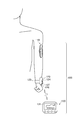
- FIG. 1A is a diagram showing an external configuration (before wearing) of a body fluid component measurement system according to an embodiment of the present invention.
- FIG. 1B is a diagram showing an external configuration (after mounting) of the body fluid component measurement system according to one embodiment of the present invention.
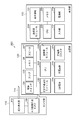
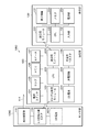
- FIG. 2 is a diagram showing a functional configuration of the body fluid component measurement system 100 according to the first embodiment of the present invention.
- FIG. 3 is a flowchart showing the flow of the monitoring process in the body fluid component measurement system 100.
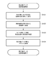
- FIG. 4 is a flowchart showing the flow of calibration value data recording processing in the body fluid component measurement system 100.
- FIG. 1A is a diagram showing an external configuration (before wearing) of a body fluid component measurement system according to an embodiment of the present invention.
- FIG. 1B is a diagram showing an external configuration (after mounting) of the body fluid component measurement system according to one embodiment of the present invention.
- FIG. 2 is a diagram showing a functional configuration of the body fluid component measurement system 100 according to the first embodiment of the present
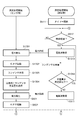
- FIG. 5 is a flowchart showing the flow of measurement processing in the sensor unit and transmission unit of the body fluid component measurement system 100.
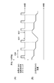
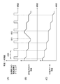
- FIG. 6 is a diagram showing the transition of the electromagnetic wave transmission timing of the transmission unit of the body fluid component measurement system 100 and the remaining amount of the secondary battery in the transmission unit.
- FIG. 7 is a diagram showing a functional configuration of a body fluid component measurement system 700 according to the second embodiment of the present invention.
- FIG. 8 is a flowchart showing the flow of measurement processing in the sensor unit and transmission unit of the body fluid component measurement system 700.
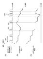
- FIG. 9 is a diagram illustrating the electromagnetic wave transmission timing of the transmission unit of the body fluid component measurement system 700, the transition of the remaining amount of the secondary battery in the transmission unit, and the transition of the remaining amount of the battery in the sensor unit.
- FIG. 10 is a diagram showing a functional configuration of a body fluid component measurement system 1000 according to the third embodiment of the present invention.
- FIG. 11A is a flowchart illustrating a flow of measurement processing in the sensor unit and the transmission unit of the body fluid component measurement system 1000.
- FIG. 11B is a flowchart illustrating a flow of measurement processing in the sensor unit and the transmission unit of the body fluid component measurement system 1000.
- FIG. 12 is a diagram illustrating the electromagnetic wave transmission timing of the transmission unit of the body fluid component measurement system 1000, the transition of the remaining amount of the secondary battery in the transmission unit, and the transition of the remaining amount of the secondary battery in the sensor unit.
- FIG. 11A is a flowchart illustrating a flow of measurement processing in the sensor unit and the transmission unit of the body fluid component measurement system 1000.
- FIG. 11B is a flowchart illustrating a flow of measurement processing in the sensor unit and the transmission unit of the body fluid component measurement system 1000.
- FIG. 12 is a diagram illustrating the electromagnetic wave transmission
- FIG. 13A is a flowchart illustrating a flow of measurement processing in the sensor unit and the transmission unit of the body fluid component measurement system 1300.
- FIG. 13B is a flowchart illustrating a flow of measurement processing in the sensor unit and the transmission unit of the body fluid component measurement system 1300.
- FIG. 14 is a diagram illustrating the electromagnetic wave transmission timing of the transmission unit of the body fluid component measurement system 1300, the transition of the remaining amount of the secondary battery in the transmission unit, and the transition of the remaining amount of the capacitor in the sensor unit.
- FIG. 15 is a diagram showing a functional configuration of a body fluid component measurement system 1500 according to the fifth embodiment of the present invention.
- FIG. 16 is a diagram illustrating an external configuration of the sensor unit 110.
- FIG. 17 is a diagram illustrating an external configuration of the sensor unit 110.
- FIG. 1A is a diagram showing an external configuration of a body fluid component measurement system 100 according to an embodiment of the present invention.
- the body fluid component measurement system 100 includes a sensor unit 110, a transmission unit 120, and a display unit 130.
- the sensor unit 110 includes a main body 111 formed in a liquid-tight structure with a flexible resin such as polyurethane.
- a waterproof skin-applying tape (not shown) is disposed on the bottom surface of the main body 111, whereby the sensor unit 110 is directly attached to the upper arm or abdomen of the subject. .
- a needle 114 that is punctured into the subject's skin and comes into contact with subcutaneous body fluid is provided on the bottom surface of the main body 111 and is connected to a component measuring unit 115 disposed in the main body 111.
- the component measuring unit 115 measures a signal corresponding to the concentration of a predetermined component such as glucose in the subcutaneous body fluid in contact with the needle 114.
- an A / D circuit built-in IC tag 116 (hereinafter simply referred to as an IC tag 116) including an antenna 112, an IC chip 113, and an A / D conversion circuit (not shown) is further provided.
- the electromagnetic wave generated in the transmission unit 120 is received and rectified into a direct current, and this is operated as a power source.
- the IC tag 116 controls the measurement by the component measurement unit 115 and stores the measurement result in the memory of the IC chip 113 or transmits it to the transmission unit 120.
- the transmission unit 120 includes a housing 121.
- the housing 121 is driven to generate an electromagnetic wave to the IC tag 116 of the sensor unit 110 by being driven, supply power, and detect the electromagnetic wave transmitted by the IC tag 116, thereby obtaining a measurement result.
- An IC tag transmission / reception module 122 for receiving a measurement signal indicating the above is disposed.
- the transmission unit 120 processes the measurement signal received from the sensor unit 110 to calculate the concentration of a predetermined component (concentration of body fluid component) contained in a body fluid such as a blood glucose level, and then transmits it via a transmission / reception module (not shown). It is assumed that the calculated concentration of the body fluid component is transmitted to the communicable display unit 130.
- a mounting tool 123 for mounting the transmitting unit 120 on the subject at a position (for example, a wrist or the like) different from the position where the sensor unit 110 is attached is provided on the side surface of the housing 121.
- the display unit 130 includes a display area 131 and displays the concentration of the body fluid component transmitted from the transmission unit 120.
- an input unit 132 is provided, which is used when performing various operations such as switching display contents displayed in the display area 131 and inputting predetermined information.
- the power supply by the transmission unit 120 and the transmission of the measurement signal by the sensor unit 110 between the sensor unit 110 and the transmission unit 120 are performed wirelessly using the IC tag 116 and the IC tag transmission / reception module 122. By doing so, it is possible to mount the transmission unit 120 at a position away from the sensor unit 110.
- the sensor unit 110 is a device that is always mounted at the position where the needle is punctured, and the device can be reduced in size and weight by the amount corresponding to the function of the transmission unit 120. .
- FIG. 1B is a diagram showing a state in which a sensor unit 110 having a needle that conducts body fluid is attached to the upper arm of the subject and the transmitter 120 is attached to the wrist of the subject.
- the transmission unit 120 is provided with a power switch 124 for turning on / off the power of the transmission unit 120.
- the power switch 124 is pressed once, the power is turned on and the lamp 125 is lit. Further, when pressed again, the power is turned off and the lamp 125 is turned off.
- the transmission unit 120 is further provided with a speaker 127. For example, when an error or the like is detected in the transmission unit 120, a sound is output to the subject. Moreover, the charging connector 126 is provided, and the secondary battery built in the transmission part 120 can be charged by connecting the charging adapter.
- the power switch 124 is pressed to turn on the power of the transmission unit 120, whereby the display unit 130 displays the concentration of a predetermined body fluid component for each predetermined period.
- the display unit 130 in FIG. 1B shows a state where the concentration of the body fluid component obtained by the current measurement is displayed in the display area 131 together with the trend graph).
- FIG. 2 is a diagram illustrating a functional configuration of the body fluid component measurement system 100.
- elements corresponding to those already described using the external configuration of FIGS. 1A and 1B are denoted by the same reference numerals.
- the sensor unit 110 includes a needle 114, a component measurement unit 115, and an IC tag 116.
- the needle 114 is a capillary that guides the body fluid to reach the component measuring unit 115, and the tip of the capillary 114 reaches the subject's skin.
- the needle 114 is connected to the component measuring unit 115 and guides body fluid into the component measuring unit 115.
- the component measuring unit 115 is a measuring means for measuring the concentration of a specific component (for example, glucose, uric acid, cholesterol, protein, mineral, blood cell, etc.) contained in a body fluid such as blood, and is a well-known measuring method. Use to measure. Examples of the body fluid conducted by the needle 114 include blood, interstitial fluid, lymph fluid, and the like.
- the measurement method is fluorescence when the fluorescent die that captures a predetermined component contained in the body fluid to be measured is irradiated with excitation light.
- a method for measuring the strength, a method for optically or electrochemically measuring a predetermined component contained in a body fluid to be measured using an oxidase, and the like are used.
- the needle 114 is inserted subcutaneously, the glucose concentration in the interstitial fluid is measured, and further converted into the glucose concentration (blood glucose level) in the blood.
- a fluorescent sensor in which a boronic acid group-introduced fluorescent dye that binds to a saccharide and exhibits a Stokes shift is fixed to a hydrogel is used. It is also possible to insert the needle 114 into the blood vessel instead of subcutaneously and measure the glucose concentration in the blood directly.
- the transmission unit 120 includes a power switch 124, a lamp 125, a memory 128, a speaker 127, an IC tag transmission / reception module 122, a CPU 222, a transmission / reception module 223, a secondary battery 224, a charging circuit 225, and a charging unit. And a connector 126.
- the power of the transmission unit 120 is turned on and the lamp 125 is lit.
- the lamp 125 may be configured to notify the user that the secondary battery 224 is low by blinking when the secondary battery 224 is low. Further, the lamp 125 may be configured to be lit in a different color depending on the internal state of the transmission unit 120 (for example, may be configured to be lit in green when normal, or red when an abnormality is detected).
- the memory 128 stores a calculation program for calculating the concentration of a predetermined component contained in body fluid based on a digital measurement signal that is a measurement result received from the sensor unit 110, and a calibration used when calculating the concentration of the body fluid component.
- a calibration program for calculating value data, a control program for controlling the entire operation of the transmission unit 120, and the like are stored.
- the memory 128 also has a function as storage means for storing the concentration of the body fluid component calculated in the past in association with the measurement time.
- Speaker 127 informs by voice of the end of measurement and the measured concentration of body fluid component. For example, when the blood glucose level obtained as a result of the measurement is normal, a short beep sound is output, and when it is abnormal, a louder warning sound is continuously output than when it is normal. .
- the IC tag transmission / reception module 122 supplies power and receives measurement signals between the transmission unit 120 and the sensor unit 110.
- the CPU 222 controls the overall operation of the transmission unit 120.
- the transmission / reception module 223 is a module that transmits the concentration of the body fluid component calculated by the transmission unit 120 to the display unit 130.
- the secondary battery 224 supplies power to each unit constituting the transmission unit 120.
- the charging circuit 225 is a circuit for charging the secondary battery 224, and charges the secondary battery 224 when power is supplied from an adapter (not shown) connected via the charging connector 126. To do.
- the display unit 130 includes a transmission / reception module 231, a CPU 232, an input unit 132, a display area 131, a memory 233, and a power supply unit 234.
- the transmission / reception module 231 receives the concentration of the body fluid component transmitted from the transmission unit 120 via the transmission / reception module 223.
- the concentration of the body fluid component received by the transmission / reception module 231 is processed by the CPU 232, displayed on the display area 131, and stored in the memory 233.
- the input unit 132 is a button or the like that receives an input instruction of the subject, and includes a power-on instruction for the display unit 130, a call instruction for the concentration of the body fluid component calculated in the past, a display switching instruction, and a body fluid component This is used to instruct information input for calculating calibration value data used in the calculation of concentration.
- the display area 131 and the input unit 132 may be configured by a single component such as a touch panel.
- the power supply unit 234 is a battery that supplies power to each unit constituting the display unit 130.
- FIG. 3 is a flowchart showing the flow of the monitoring process in the body fluid component measurement system 100.
- the measurement target body fluid interstitial fluid
- the concentration calculation target component blood glucose (that is, the case where the blood glucose level is calculated as the concentration of the body fluid component will be described). To do).
- step S301 the subject wears the sensor unit 110 on the upper arm or the abdomen. Specifically, the needle 114 is punctured into the skin of the upper arm or abdomen, and the main body 111 is brought into close contact with the skin by a waterproof skin-applying tape disposed on the bottom surface of the main body 111.
- step S302 the transmitting unit 120 is attached to a position (for example, wrist) different from the position where the sensor unit 110 is attached.
- step S303 the power switch 124 of the transmission unit 120 is pressed to turn on the power of the transmission unit 120. Thereby, the transmission part 120 starts and communication between the transmission part 120 and the display part 130 is established.
- step S304 the calculated calibration value data is recorded in the memory 128.
- the details of the calibration value data recording process (step S304) will be described later.
- step S305 measurement is performed at predetermined intervals and a blood glucose level is displayed.
- the process proceeds to step S306 to determine whether or not to continue the monitoring process. If it is determined in step S306 that the monitoring process is to be continued, the process returns to step S305, the measurement is performed after a predetermined period, and the blood glucose level is displayed. On the other hand, when it determines with not continuing monitoring processing in step S306, it progresses to step S307.
- step S307 it is determined whether or not recalibration is to be performed. If it is determined that recalibration is to be performed, the process returns to step S304 to perform calibration value data recording processing. On the other hand, if it is determined not to recalibrate, the monitoring process is terminated.
- FIG. 4 is a flowchart showing a detailed flow of the calibration value data recording process (step S304).
- step S401 the subject inputs the blood glucose level obtained by measuring using SMBG (Self Monitoring of Blood Glucose) or the like via the display unit 130.
- SMBG Self Monitoring of Blood Glucose
- the transmission / reception module 231 transmits the input blood glucose level to the transmission unit 120 in step S ⁇ b> 402.
- step S403 the IC tag transmission / reception module 122 is activated to generate electromagnetic waves to the sensor unit 110. Thereby, the sensor part 110 starts and the component measurement part 115 measures the glucose level in interstitial fluid. Since the measurement result is transmitted to the transmission unit 120 via the IC tag 116, the transmission unit 120 receives the measurement result.
- step S404 the transmission unit 120 activates the calibration program, and calculates the blood glucose level based on the blood glucose level transmitted from the display unit 130 in step S401 and the measurement result transmitted from the sensor unit 110 in step S403. Calculate the calibration value data for the formula.
- the calculated calibration value data is recorded in the memory 128.
- FIG. 5 is a flowchart showing a detailed flow of the measurement process (step S305).
- step S511 When the measurement process is started in the transmission unit 120, in step S511, a timer that defines a measurement interval for performing measurement at a predetermined period is operated. In step S512, it is determined whether the timer has counted for a predetermined time. If it is determined in step S512 that the predetermined time has been counted, the process proceeds to step S513.
- step S513 the IC tag transmission / reception module 122 is driven to generate an electromagnetic wave.
- step S501 power is generated in the IC tag 116 by receiving electromagnetic waves generated from the IC tag transmission / reception module 122 (that is, power is supplied from the transmission unit 120 to the sensor unit 110).
- step S502 the IC tag 116 is activated to supply power to the component measurement unit 115 and operate the component measurement unit 115.
- step S503 in the component measuring unit 115, the interstitial fluid sucked from the needle 114 has reached the hydrogel carrying the sugar-responsive fluorescent dye, and the hydrogel is irradiated with excitation light. Furthermore, the fluorescence intensity with respect to the irradiated excitation light is measured.
- step S504 the fluorescence intensity measured in step S503 is converted into a digital signal and recorded as a measurement result in a memory in the IC tag 116.
- step S ⁇ b> 505 the IC tag 116 transmits a measurement signal indicating the fluorescence intensity converted into the digital signal to the IC tag transmission / reception module 122.
- step S514 when the transmission unit 120 receives the measurement signal transmitted from the sensor unit 110, the calculation formula and calibration value data recorded in advance in the memory 128 are read, and the received measurement signal and the read calculation are read out.
- the blood glucose level is calculated using the formula and the calibration value data.
- step S515 the blood glucose level calculated in step S514 is transmitted to the display unit 130.
- step S516 it is determined whether or not to continue the measurement process.
- the blood glucose level is calculated by the transmission unit 120 and the blood glucose level is transmitted to the display unit 130.
- the measurement signal is transmitted from the transmission unit 120 to the display unit 130.
- the blood glucose level may be calculated by the display unit 130 based on the measurement signal transmitted.
- step S516 If it is determined in step S516 that the measurement process is to be continued, the process returns to step S512 and the measurement process is continued. On the other hand, if it is determined in step S516 that the measurement process is not continued, the measurement process ends.
- FIG. 6 is a schematic diagram illustrating the transition of the electromagnetic wave transmission timing of the transmission unit 120 and the remaining amount of the secondary battery 224 during the measurement process of the body fluid component measurement system 100.
- the transmitter 120 is temporarily removed and charged (timing 601). .
- the remaining amount of the secondary battery 224 in the transmission unit 120 increases, and charging is completed at timing 602. Thereafter, when the subject attaches the transmitter 120 to the subject again and turns on the power, the measurement process is resumed, and the IC tag transmission / reception module 122 is driven again every predetermined period 600, and the component measurement unit 115 is resumed. The measurement is performed. As a result, the remaining amount of the secondary battery 224 decreases every predetermined period 600.
- the body fluid component measurement system 100 does not include a battery in the sensor unit 110 that is always worn by the subject, and supplies power to the sensor unit 110 by transmitting electromagnetic waves from the transmission unit 120. Depending on the transmission timing of the transmission unit 120, the remaining amount of the secondary battery 224 will decrease.
- the transmission unit 120 is configured to be detachable from the subject and is configured to be rechargeable, it can be easily charged as necessary. That is, the configuration is suitable for continuously monitoring the concentration of the body fluid component.
- the IC tag 116 and the IC tag transmission / reception module perform power supply and measurement signal transmission between the sensor unit 110 and the transmission unit 120. 122.
- the senor unit does not incorporate a battery, and the transmission unit 120 supplies all the power necessary for measurement in the component measurement unit 115.
- the present invention is not limited to this, and a battery may be built in the sensor unit, and the built-in battery may supply power necessary for measurement by the component measurement unit 115.
- FIG. 7 is a diagram illustrating a functional configuration of the body fluid component measurement system 700 according to the present embodiment. In the following description, differences from the body fluid component measurement system 100 shown in FIG. 2 will be mainly described.
- reference numeral 711 denotes a button-type small primary battery (such as an alkaline battery or a lithium battery), which supplies power to the component measuring unit 115.
- the IC tag 116 receives the electromagnetic wave generated in the transmission unit 120, converts it into electric power, starts up, and controls the component measurement unit 115 to operate by the electric power of the primary battery 711.
- a digital measurement signal obtained by A / D converting the measurement result from the component measurement unit 115 is transmitted to the transmission unit 120.
- the body fluid component measurement system 700 has a configuration in which the primary battery 711 is built in the sensor unit 710 and the component measurement unit 115 is operated by the power supplied from the primary battery 711.
- the measurement by the component measuring unit 115 can be performed stably.
- the power received by the IC tag 116 or the power supplied from the primary battery 711 is used.
- FIG. 8 is a flowchart showing a detailed flow of the measurement process (step S305) in the body fluid component measurement system 700.
- step S511 to step S516 is the same as the processing from step S511 to step S516 of FIG. 5 in the first embodiment, and thus description thereof is omitted here.
- step S513 power is generated in the IC tag 116 in step S501 by driving the IC tag transmission / reception module 122 and transmitting electromagnetic waves.
- step S801 the IC tag 116 is activated and control is performed so that power is supplied from the primary battery 711 to the component measurement unit 115.
- step S802 supply of electric power from the primary battery 711 to the component measuring unit 115 is started, and the component measuring unit 115 is activated.
- step S503 to step S505 Since the processing from step S503 to step S505 is the same as the processing from step S503 to step S505 in FIG. 5, the description thereof is omitted here.
- step S803 the IC tag 116 controls to end the supply of power from the primary battery 711 to the component measuring unit 115. Thereby, the supply of power from the primary battery 711 to the component measuring unit 115 is completed.
- FIG. 9 is a schematic diagram showing the transmission timing of the transmission unit 120, the transition of the remaining amount of the secondary battery 224, and the transition of the remaining amount of the primary battery 711 of the sensor unit 710 during the measurement process of the body fluid component measurement system 700. is there.
- the IC tag transmission / reception module 122 is driven every predetermined cycle 600, and the IC tag 116 is activated.
- the remaining amount of the secondary battery 224 decreases every predetermined period 600.
- power is supplied from the primary battery 711 to the component measuring unit 115, and measurement is performed in the component measuring unit 115.
- the remaining amount of the primary battery 711 also decreases every predetermined period 600.
- the transmitter 120 is temporarily removed and charged (timing 601). .
- the remaining amount of the secondary battery 224 increases, and charging is completed at timing 602. Thereafter, when the subject attaches the transmitter 120 to the subject again and turns on the power, the measurement process is resumed, and the IC tag transmission / reception module 122 is driven every predetermined cycle 600, and the IC tag 116 is turned on. Starts. As a result, the remaining amount of the secondary battery 224 in the transmission unit 120 decreases every predetermined period 600.
- the primary battery 711 continues to decrease at every predetermined period 600 without being charged. For this reason, the primary battery 711 has a configuration corresponding to the upper limit of the measurement frequency within the replacement period of the sensor unit 710.
- the IC tag 116 supplies power for starting the IC tag and transmits the measurement signal between the sensor unit 710 and the transmission unit 120. And the IC tag transmission / reception module 122. Further, the sensor unit 110 is configured to incorporate a battery as a power source for measurement.
- FIG. 10 is a diagram illustrating a functional configuration of the body fluid component measurement system 1000 according to the present embodiment. In the following, the description will focus on differences from the body fluid component measurement system 200 shown in FIG. 2 or the body fluid component measurement system 700 shown in FIG.
- reference numeral 1011 denotes a button-type small secondary battery (such as a lithium ion battery), which supplies power to the component measuring unit 115.
- the IC tag 116 receives the electromagnetic wave generated in the transmission unit 120, converts it into electric power, starts with the electric power, and controls the component measurement unit 115 to operate by the power source of the secondary battery 1011.
- a digital measurement signal obtained by A / D converting the measurement result from the component measurement unit 115 is transmitted to the transmission unit 120.
- the secondary battery 1011 is charged with the electric power generated by the electromagnetic wave transmitted from the transmission unit 120.
- the secondary battery 1011 is built in the sensor unit 1010, and the component measurement unit 115 is operated by the power supplied from the secondary battery 1011.
- the measurement by the component measuring unit 115 can be performed stably.
- the secondary battery 1011 can be charged when the remaining amount of the secondary battery 1011 becomes a predetermined value or less, the problem of power outage in the sensor unit 1010 is also solved, and a sensor that consumes a large amount of power. Can also be used.
- the power received by the IC tag 116 or the power supplied from the secondary battery 1011 is used.
- 11A and 11B are flowcharts showing the detailed flow of the measurement process (step S305) in the body fluid component measurement system 1000.
- step S511 to step S515 is the same as the processing from step S511 to step S515 of FIG. 8 in the second embodiment, and thus description thereof is omitted here.
- step S513 power is generated in the IC tag 116 in step S501 by driving the IC tag transmission / reception module 122 and transmitting electromagnetic waves.
- step S1101 the IC tag 116 is activated to control power supply from the secondary battery 1011 to the component measurement unit 115.
- step S1102 power is supplied from the secondary battery 1011 to the component measuring unit 115, and the component measuring unit 115 is activated.
- step S503 to step S504 Since the processing from step S503 to step S504 is the same as the processing from step S503 to step S504 in FIG. 8, description thereof is omitted here.
- step S1103 the IC tag 116 transmits a measurement signal indicating the fluorescence intensity converted into a digital signal to the IC tag transmission / reception module 122. Further, the IC tag 116 detects the remaining amount of the secondary battery 1011 and transmits the detection result to the IC tag transmission / reception module 122 as secondary battery remaining amount data.
- step S1104 the IC tag 116 controls to end the supply of power from the secondary battery 1011 to the component measuring unit 115. Thereby, the supply of power from the secondary battery 1011 to the component measuring unit 115 is terminated.
- the transmitter 120 that has received the measurement signal transmitted from the sensor unit 1010 determines whether or not the secondary battery remaining amount data transmitted from the sensor unit 1010 is equal to or less than a predetermined value in step S1111. If it is determined in step S1111 that the secondary battery remaining amount data is equal to or less than the predetermined value, the process proceeds to step S1112. If it is determined that the secondary battery remaining capacity data is not equal to or less than the predetermined value, the process proceeds to step S516 (note that step S516). The process in is the same as the process in step S516 in FIG.
- step S1112 the IC tag transmission / reception module 122 is driven to transmit electromagnetic waves.
- step S1105 the IC tag 116 determines whether the secondary battery remaining amount data is equal to or less than a predetermined value. If it is determined in step S1105 that the secondary battery remaining amount data is equal to or less than the predetermined value, the process proceeds to step S1106, and received by the IC tag 116 along with the supply of power from the transmission unit 120 in step S1112. Control is performed so that power is stored in the secondary battery 1011. Thereby, in step S1106, the secondary battery 1011 is charged.
- step S1105 if it is determined in step S1105 that the secondary battery remaining amount data is not less than or equal to the predetermined value, the measurement process is terminated.
- FIG. 12 is a schematic diagram illustrating the electromagnetic wave transmission timing of the transmission unit 120, the transition of the remaining amount of the secondary battery 224, and the transition of the remaining amount of the secondary battery 1011 of the sensor unit 1010 during the measurement process of the body fluid component measurement system 1000. It is.
- the transmitter 120 is temporarily removed and charged (timing 601). .
- the remaining amount of the secondary battery 224 increases, and charging is completed at timing 602. Thereafter, when the subject wears the transmitter 120 again and turns on the power, the measurement process is resumed. Then, the IC tag transmission / reception module 122 is driven every predetermined cycle 600, and the IC tag 116 is activated. As a result, the remaining amount of the secondary battery 224 decreases every predetermined period 600.
- the secondary battery 1011 continuously decreases every predetermined period 600, but when it is determined that the remaining amount has become a predetermined value or less, the transmission unit 120 changes the transmission frequency to change the IC tag transmission / reception module. By driving 122, an electromagnetic wave for charging the secondary battery 1011 is transmitted (timing 1201). However, even in this case, the subsequent measurement frequency is not changed.
- the remaining amount of the secondary battery 224 of the transmission unit 120 decreases, but the remaining amount of the secondary battery 1011 of the sensor unit 1010 increases. That is, the secondary battery 1011 in the sensor unit 1010 can have a capacity that does not depend on the measurement frequency within the replacement period of the sensor unit 1010.
- the body fluid component measurement system 1000 according to the present embodiment, power supply for starting the IC tag between the sensor unit 1010 and the transmission unit 120 is supplied, and power supply for charging the secondary battery is supplied.
- the measurement signal is transmitted using the IC tag 116 and the IC tag transmission / reception module 122, and the sensor unit 1010 is configured to incorporate a secondary battery as a power source for measurement.
- the secondary battery is configured to charge the secondary battery after measuring the biological component and transmitting the measurement signal first, but after charging the secondary battery first, You may comprise so that a measurement of a component and transmission of a measurement signal may be performed. Thereby, since it charges immediately before a measurement etc., electric power can be reliably supplied to a measurement etc.
- a rechargeable secondary battery is built in the sensor unit.
- the present invention is not limited to this, and a capacitor (capacitor) is arranged in the sensor unit to charge the capacitor. It is good also as a structure.
- the functional configuration of the bodily fluid component measurement system in the present embodiment is the same as the functional configuration described with reference to FIG. 2 in the first embodiment, and thus the description thereof is omitted here.
- the IC tag 116 disposed in the sensor unit 110 further includes a capacitor.
- a body fluid component measurement system including the IC tag 116 with a built-in capacitor will be described as a body fluid component measurement system 1300.
- the IC tag 116 with a built-in capacitor is activated by the power generated by the electromagnetic wave transmitted from the transmission unit 120 and stores the power in the capacitor. And it controls so that the component measurement part 115 operate
- the component measurement unit 115 is configured such that the capacitor is built in the sensor unit 110 and the component measurement unit 115 is operated by the electric power stored in the capacitor. Measurement can be performed stably.
- FIG. 13A and 13B are flowcharts showing the detailed flow of the measurement process (step S305) in the body fluid component measurement system 1300.
- step S511 to step S512 is the same as the processing from step S511 to step S512 of FIG. 5 according to the first embodiment, and thus description thereof is omitted.
- step S1313 the IC tag transmission / reception module 122 is driven to transmit an electromagnetic wave, and in step S1301, power is generated in the IC tag 116.
- step S1302 the IC tag 116 is activated, and in step S1303, a part of the generated power is charged in the capacitor.
- step S1304 the amount of charge charged in the capacitor is transmitted to the transmission unit 120.
- the transmission unit 120 determines in step S1314 whether the capacitor charge amount is equal to or less than a predetermined value. If it is determined in step S1314 that the value is equal to or less than the predetermined value, the process returns to step S1313 and the above process is repeated until the capacitor charge exceeds the predetermined value. On the other hand, if it is determined in step S1314 that the value is not less than the predetermined value, the process proceeds to step S513.
- step S513 to step S516 Since the processing from step S513 to step S516 is the same as the processing from step S513 to step S516 in FIG. 5 according to the first embodiment, description thereof will be omitted.
- step S513 the IC tag transmission / reception module 122 is driven to transmit an electromagnetic wave, so that power is generated in the IC tag 116 in step S501.
- step S502 the IC tag 116 is activated.
- step S1305 supply of power from the capacitor to the component measuring unit 115 is started, and the component measuring unit 115 is activated.
- step S503 to step S505 Since the processing from step S503 to step S505 is the same as the processing from step S503 to step S505 in FIG. 5, the description thereof is omitted here.
- step 1306 the IC tag 116 controls to end the supply of power from the capacitor to the component measuring unit 115. Thereby, the supply of power from the capacitor to the component measuring unit 115 is completed.
- FIG. 14 is a schematic diagram showing the electromagnetic wave transmission timing of the transmission unit 120, the transition of the remaining amount of the secondary battery 224, and the transition of the remaining amount of the capacitor of the sensor unit 110 during the measurement process of the body fluid component measurement system 1300.
- the IC tag transmission / reception module 122 transmits an electromagnetic wave twice in a predetermined cycle 600, and the IC tag 116 is activated.
- the remaining amount of the secondary battery 224 decreases every predetermined period 600.
- the capacitor is charged as the IC tag 116 is activated for the first time, and the supply of power from the capacitor to the component measuring unit 115 is started as the IC tag 116 is driven for the second time. Done.
- the remaining amount of the capacitor decreases, and after the measurement is completed, the remaining amount gradually decreases due to spontaneous discharge.
- the transmitter 120 is temporarily removed from the sensor unit 110 and charged. (Timing 601).
- the remaining amount of the secondary battery 224 increases, and charging is completed at timing 602. Thereafter, when the subject attaches the transmitter 120 to the sensor unit 110 again and turns on the power, the measurement process is resumed, and the IC tag transmission / reception module 122 again transmits the electromagnetic wave twice every predetermined period 600. Each IC tag 116 is activated. As a result, the remaining amount of the secondary battery 224 decreases every predetermined period 600. On the other hand, the capacitor is repeatedly charged and discharged every predetermined period 600.
- the body fluid component measurement system 1300 according to the present embodiment, power supply for IC tag activation, power supply and measurement for capacitor charging between the sensor unit 110 and the transmission unit 120 are performed.
- the signal transmission is performed using the IC tag 116 and the IC tag transmission / reception module 122, and the sensor unit 110 is configured to incorporate a capacitor as a power source for measurement.
- the blood sugar level obtained by measuring in advance by SMBG is input via the display unit 130, whereby the transmission unit 120 calculates the calibration value data.
- the present invention is not limited to this.
- a blood glucose meter used for SMBG may be provided with an IC tag, and the blood glucose level for calibration may be directly input from the blood glucose meter to the transmission unit 120 via the IC tag transmission / reception module 122.
- FIG. 15 is a diagram illustrating a functional configuration of a body fluid component measurement system 1500 that directly receives a blood glucose level for calibration from an external blood glucose meter (not shown) by a transmission unit 1520.
- a body fluid component measurement system 1500 that directly receives a blood glucose level for calibration from an external blood glucose meter (not shown) by a transmission unit 1520.
- the display module 1531 is provided with a receiving module 1531 instead of the transmitting / receiving module.
- the transmission unit 1520 since it is not necessary to receive information for calculating the calibration value data from the display unit 1530, the transmission unit 1520 includes a transmission module 1523 instead of the transmission / reception module. As a result, a simpler system can be constructed.
- the first to fifth embodiments have been described above with reference to FIGS. 1 to 15, but the present invention is not limited to these embodiments.
- the case where the electromagnetic wave method is used as the power and data transmission method between the IC tag 116 and the IC tag transmission / reception module 122 has been described.
- the present invention is not limited to this.
- an electromagnetic induction method may be used.
- a passive tag was used was demonstrated as a kind of tag, you may use another kind of tag. That is, the present invention may use any communication method as long as it is a near-field or near-field communication method used as an RFID tag.
- the communication performed between the IC tag 116 and the IC tag transmission / reception module 122 is used as the communication between the IC tag 116 and the IC tag transmission / reception module 122.
- the present invention is not limited to this, and may be configured to perform communication via the human body between the IC tag 116 and the IC tag transmission / reception module (that is, configured to perform human body communication). ).
- the fluorescence sensor for measuring the fluorescence intensity is used as the blood glucose level measurement method.
- the present invention is not limited to this, and other measurement methods (for example, GOD) Sensor) may be used.
- the interstitial fluid is particularly measured, and the blood glucose level is calculated based on the amount of glucose contained in the interstitial fluid.
- Any body fluid component may be used as long as it is a body fluid component that can be measured by a known measurement method and the concentration can be calculated.
- concentration of various components such as a mineral contained in blood, protein, and a lipid, may be calculated.
- the needle 114 connected to the component measuring unit 115 is provided at the center of the bottom surface of the sensor unit 110, and the needle is punctured in a direction substantially perpendicular to the bottom surface.
- the needle may be configured to be removable while being configured to puncture obliquely.
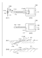
- FIG. 16 is a diagram illustrating an external configuration of a sensor unit 1600 (sensor unit capable of puncturing obliquely with respect to a subject) and a puncturing state thereof according to the present embodiment.
- (A-1) is a side view of the sensor unit 1600
- (A-2) is a plan view of the sensor unit 1600 with the introduction needle 1614 attached
- (A-3) is an introduction needle. It is a top view of sensor part 1600 of a state where 1614 was removed.
- the sensor unit 1600 is provided with a puncture portion 1619 extending substantially parallel to the bottom surface of the sensor unit 1600 from the side surface end portion of the main body portion 111, and at the tip of the puncture portion 1619.
- a component measuring unit 115 is attached.
- the main body portion 111 and the puncture portion 1619 are made of one member and have flexibility.
- an IC tag 116 including an antenna 112, an IC chip 113, and an A / D conversion circuit (not shown) is provided inside the main body 111, and power generated by electromagnetic waves transmitted from the transmission unit 120 is supplied as a power source. And the measurement by the component measuring unit 115 is controlled, and the measurement result is stored in the memory of the IC chip 113 or transmitted to the transmitting unit 120.
- an introduction needle 1614 is detachably attached to the side surface of the main body 111, the component measurement unit 115, and the puncture unit 1619.
- the introduction needle 1614 is punctured into the subject's skin, so that the component measurement unit 115 and the puncture unit 1619 disposed inside the introduction needle 1614 are guided subcutaneously to the subject. It is burned. Thereby, the component measuring unit 115 comes into contact with the body fluid.
- the introduction needle 1614 attached so as to cover the component measurement unit 115 and the puncture unit 1619 is provided with a notch 1618 over the entire length. For this reason, the introduction needle 1614 can be removed after being guided through the skin of the subject by guiding the component measurement unit 115 under the skin of the subject.
- FIG. (B-1) shows a state where the component measuring unit 115 is punctured by the introduction needle 1614 into the skin of the subject. As shown in (B-1), the component measuring unit 115 is guided subcutaneously by introducing the introduction needle 1614 into the subject's skin obliquely.
- the introduction needle 1614 is removed by pulling out the introduction needle 1614 in the direction of the arrow while being punctured into the skin of the subject. Can do.
- (B-2) is a view showing a state in which only the introduction needle 1614 is removed after the skin of the subject has been punctured.
- the main body portion 111 and the puncture portion 1619 are formed of a resin such as polyimide.
- the puncture portion 1619 is bent so as to bend around a portion not inserted into the skin after the introduction needle 1614 is removed, and the main body portion 111 is cut off by the adhesive (not shown) provided on the lower surface thereof. Will be pasted along. Since the IC chip 113 and the A / D conversion circuit (not shown) have a thickness, the IC chip 113 and the A / D conversion circuit (not shown) are arranged so as to avoid a portion through which the introduction needle 1614 passes.
- the bodily fluid component measurement system shown in the first to fifth embodiments is configured using the sensor unit (sensor unit configured to be punctured obliquely and the needle is detachable) shown in FIG. Is possible.
- FIG. 17 is a diagram showing an external configuration of a sensor unit 1700 (sensor unit capable of puncturing obliquely with respect to a subject) and its puncture state in the present embodiment.
- (A-1) is a side view of the sensor unit 1700
- (A-2) is a plan view of the sensor unit 1700 with the introduction needle 1714 attached
- (A-3) is an introduction needle. It is a top view of sensor part 1700 of a state where 1714 was removed.
- the sensor unit 1700 is provided with a puncture unit 1719 extending substantially parallel to the bottom surface of the sensor unit 1700 from the center of the side surface of the main body unit 111.
- a measurement unit 115 is attached.
- the main body part 111 and the puncture part 1719 are made of one member and have flexibility.
- an IC tag 116 including an antenna 112, an IC chip 113, and an A / D conversion circuit (not shown) is provided inside the main body 111, and power generated by electromagnetic waves transmitted from the transmission unit 120 is supplied as a power source. And the measurement by the component measuring unit 115 is controlled, and the measurement result is stored in the memory of the IC chip 113 or transmitted to the transmitting unit 120.
- an introduction needle 1714 is detachably attached to the component measurement unit 115 and the puncture unit 1719.
- the introduction needle 1714 is punctured into the subject's skin, so that the component measurement unit 115 and the puncture unit 1719 disposed inside the introduction needle 1714 are guided subcutaneously to the subject. It is burned. Thereby, the component measuring unit 115 comes into contact with the body fluid.
- the introduction needle 1714 attached so as to cover the component measurement unit 115 and the puncture unit 1719 is provided with a notch 1718 over the entire length. For this reason, the introduction needle 1714 can be removed by pulling the knob portion 1714A after guiding the component measurement unit 115 under the skin of the subject by being punctured into the skin of the subject.
- FIG. (B-1) shows a state in which the component measurement unit 115 is punctured by the introduction needle 1714 into the skin of the subject. As shown in (B-1), the component measuring unit 115 is guided subcutaneously by introducing the introduction needle 1714 into the subject's skin obliquely.
- the main body 111 and the puncture portion 1719 are formed of a resin such as polyimide. After the introduction needle 1714 is obliquely punctured into the skin of the subject, the puncture portion 1719 is centered on a portion not inserted into the skin. The main body 111 is affixed along the skin of the subject by an adhesive (not shown) provided on the lower surface thereof. Thereafter, the introduction needle 1714 is withdrawn from the skin, and the mounting of the sensor unit 1700 is completed.
- the introduction needle 1714 is provided with the notch portion 1718, the introduction needle 1714 is introduced by pulling the introduction needle 1714 in the direction of the arrow by pulling the knob portion 1714A while being punctured into the skin of the subject. Only the needle 1714 can be removed.
- (B-2) is a view showing a state in which only the introduction needle 1714 is removed after the skin of the subject has been punctured.
- the bodily fluid component measurement systems shown in the first to sixth embodiments are configured using the sensor unit (sensor unit configured to be punctured obliquely and configured to be detachable) as shown in FIG. Is possible.
Landscapes
- Health & Medical Sciences (AREA)
- Life Sciences & Earth Sciences (AREA)
- Physics & Mathematics (AREA)
- Surgery (AREA)
- General Health & Medical Sciences (AREA)
- Engineering & Computer Science (AREA)
- Biomedical Technology (AREA)
- Heart & Thoracic Surgery (AREA)
- Medical Informatics (AREA)
- Molecular Biology (AREA)
- Biophysics (AREA)
- Animal Behavior & Ethology (AREA)
- Pathology (AREA)
- Public Health (AREA)
- Veterinary Medicine (AREA)
- Optics & Photonics (AREA)
- Chemical & Material Sciences (AREA)
- Chemical Kinetics & Catalysis (AREA)
- General Chemical & Material Sciences (AREA)
- Spectroscopy & Molecular Physics (AREA)
- Measurement Of The Respiration, Hearing Ability, Form, And Blood Characteristics Of Living Organisms (AREA)
- Measuring And Recording Apparatus For Diagnosis (AREA)
Abstract
体液成分測定システムにおいて、センサが留置される位置において常時装着される機器を小型・軽量化することにより、被検者の利便性を向上させる。本発明に係る体液成分測定システムは、被検者の皮膚に留置され、該被検者の体液に導通されて所定の体液成分を測定するセンサ部110と、センサ部110が留置される位置とは異なる位置において前記被検者に着脱可能に取り付けられ、センサ部110において測定された測定信号または、該測定信号を元に前記体液成分の前記体液と同種または異種の体液中の濃度として算出された算出結果を表示部130に送信する送信部120と、を備え、センサ部110は送信部120が発生する電磁波によって電力供給を受けて起動されることで、前記体液成分の測定と、前記測定信号の送信部120への送信とを行うことを特徴とする。
Description
本発明は、被検者の体液を連続的に測定し、体液に含まれる所定の成分の濃度を表示する体液成分測定システムに関するものである。より詳細には、被検者の間質液を間歇的かつ連続的に測定し、血糖値を表示する体液成分測定システムに関するものである。
従来、糖尿病患者が自ら血糖値を測定し管理するために、指先などを専用の穿刺器具で穿刺して出た血液を、その都度、血糖測定器で測定する、所謂自己血糖測定(Self Monitoring of Blood Glucose:SMBG)が広く普及している。
また、近年、これに代わるべく、専用のセンサ部に配された針を皮下等に穿刺することで該センサ部を患者の皮下に留置し、血糖値を連続的にモニタリングする連続血糖測定(Continuous Glucose Monitoring:CGM)に用いる体液成分測定システムが開発され(例えば、特許文献1参照)、現在、欧米では実用化されている。
CGMに用いる体液成分測定システムは、患者に常時装着されるセンサ部と、該センサ部に取り付けられ、該センサ部における測定信号を外部に送信する送信部と、該送信部より送信された測定信号を基に血糖値を算出し表示する表示装置とから構成されている。このため、患者は、センサが留置される位置(例えば、患者の上腕部や腹部等)に、送信部が取り付けられたセンサ装置を常時装着した状態で日常生活を送ることとなる。
しかしながら、上記特許文献1のように、針を用いてセンサ部が留置される上腕部や腹部等の位置において、センサ部に取り付けられる送信部は、表示装置に送信するための送信機能およびセンサ部に電力を供給するための電源を備えるため、所定の大きさ及び重量を有する。このため、患者は、当該位置における送信部の存在を常に意識しながら(つまり、送信部に触れないように意識しながら、あるいは、上腕部や腹部に多少の違和感を感じながら)日常生活を送ることとなり、利便性が悪い。このようなことから、センサが留置される位置において常時装着される機器は、極力、小型化・軽量化されることが望ましい。また、センサ部と送信部との間には電力や測定信号の伝送のための電気接点が配されているため、入浴や水泳の際、電気接点が水に濡れないように防水手段を設ける必要があり、使い勝手の低下やコストの増加が不可避である。
本発明は上記課題に鑑みてなされたものであり、体液成分測定システムにおいて、センサが留置される位置において常時装着される機器を小型・軽量化することにより、被検者の利便性を向上させるとともに、センサ部に送信部との電気接点を設けないことで簡素な装置を提供することを目的とする。
上記の目的を達成するために、本発明に係る体液成分測定システムは以下のような構成を備える。即ち、
被検者の皮膚に留置され、該被検者の体液に導通されて所定の体液成分を測定するセンサ部と、
前記センサ部が留置される位置とは異なる位置において被検者に着脱可能に取り付けられ、前記センサ部において測定された測定信号または、該測定信号を元に前記体液成分の前記体液と同種または異種の体液中の濃度として算出された算出結果を表示装置に送信する送信部と、を備え、
前記センサ部は前記送信部が発生する電磁波によって電力供給を受けて起動されることで、前記体液成分の測定と、前記測定信号の前記送信部への送信とを行うことを特徴とする。
被検者の皮膚に留置され、該被検者の体液に導通されて所定の体液成分を測定するセンサ部と、
前記センサ部が留置される位置とは異なる位置において被検者に着脱可能に取り付けられ、前記センサ部において測定された測定信号または、該測定信号を元に前記体液成分の前記体液と同種または異種の体液中の濃度として算出された算出結果を表示装置に送信する送信部と、を備え、
前記センサ部は前記送信部が発生する電磁波によって電力供給を受けて起動されることで、前記体液成分の測定と、前記測定信号の前記送信部への送信とを行うことを特徴とする。
本発明によれば、体液成分測定システムにおいて、センサが留置される部位において常時装着される機器装置を小型化・軽量化することにより、被検者の利便性が向上する。また、センサ部に電気接点を有さないので特別な防水手段を設ける必要がない。
本発明のその他の特徴及び利点は、添付図面を参照とした以下の説明により明らかになるであろう。なお、添付図面においては、同じ若しくは同様の構成には、同じ参照番号を付す。
添付図面は明細書に含まれ、その一部を構成し、本発明の実施の形態を示し、その記述と共に本発明の原理を説明するために用いられる。
図1Aは、本発明の一実施形態に係る体液成分測定システムの外観構成(装着前)を示す図である。
図1Bは、本発明の一実施形態に係る体液成分測定システムの外観構成(装着後)を示す図である。
図2は、本発明の第1の実施形態に係る体液成分測定システム100の機能構成を示す図である。
図3は、体液成分測定システム100におけるモニタリング処理の流れを示すフローチャートである。
図4は、体液成分測定システム100における校正値データ記録処理の流れを示すフローチャートである。
図5は、体液成分測定システム100のセンサ部及び送信部における測定処理の流れを示すフローチャートである。
図6は、体液成分測定システム100の送信部の電磁波発信タイミング及び送信部内の2次電池の残量の推移を示す図である。
図7は、本発明の第2の実施形態に係る体液成分測定システム700の機能構成を示す図である。
図8は、体液成分測定システム700のセンサ部及び送信部における測定処理の流れを示すフローチャートである。
図9は、体液成分測定システム700の送信部の電磁波発信タイミング及び送信部内の2次電池の残量の推移、センサ部内の電池の残量の推移を示す図である。
図10は、本発明の第3の実施形態に係る体液成分測定システム1000の機能構成を示す図である。
図11Aは、体液成分測定システム1000のセンサ部及び送信部における測定処理の流れを示すフローチャートである。
図11Bは、体液成分測定システム1000のセンサ部及び送信部における測定処理の流れを示すフローチャートである。
図12は、体液成分測定システム1000の送信部の電磁波発信タイミング及び送信部内の2次電池の残量の推移、センサ部内の2次電池の残量の推移を示す図である。
図13Aは、体液成分測定システム1300のセンサ部及び送信部における測定処理の流れを示すフローチャートである。
図13Bは、体液成分測定システム1300のセンサ部及び送信部における測定処理の流れを示すフローチャートである。
図14は、体液成分測定システム1300の送信部の電磁波発信タイミング及び送信部内の2次電池の残量の推移、センサ部内のコンデンサの残量の推移を示す図である。
図15は、本発明の第5の実施形態に係る体液成分測定システム1500の機能構成を示す図である。
図16は、センサ部110の外観構成を示す図である。
図17は、センサ部110の外観構成を示す図である。
以下、必要に応じて添付図面を参照しながら本発明の各実施形態の詳細を説明する。なお、本発明は以下の実施形態に限定されるものではなく、適宜変更可能であるものとする。
[第1の実施形態]
以下、本発明の各実施形態について図面を参照しながら説明する。
以下、本発明の各実施形態について図面を参照しながら説明する。
<1.体液成分測定システムの外観構成>
図1Aは、本発明の一実施形態に係る体液成分測定システム100の外観構成を示す図である。
図1Aは、本発明の一実施形態に係る体液成分測定システム100の外観構成を示す図である。
図1Aに示すように、体液成分測定システム100はセンサ部110と、送信部120と、表示部130とを備える。
センサ部110は、ポリウレタンなどの柔軟な樹脂により液密構造に形成された本体部111を備える。本体部111の底面には防水機能付きの皮膚貼り付けテープ(不図示)が配されており、これにより、センサ部110は、被検者の上腕部または腹部などに直接貼り付けられることとなる。
また、本体部111の底面には、被検者の皮膚に穿刺され皮下の体液と接触する針114が設けられており、本体部111内に配された成分測定部115と接続されている。成分測定部115は、針114が接触する皮下の体液におけるグルコース等の所定成分の濃度に応じた信号を測定する。
本体部111の内部には、更に、アンテナ112とICチップ113と不図示のA/D変換回路とを備えるA/D回路内蔵ICタグ116(以下、単にICタグ116と称す)が設けられており、送信部120において発生した電磁波を受け取り整流して直流とし、それを電源として動作する。該ICタグ116は、成分測定部115による測定を制御するとともに、測定結果をICチップ113のメモリ内に記憶したり、送信部120に送信したりする。
送信部120は、ハウジング121を備える。ハウジング121の内部には、駆動されることによりセンサ部110のICタグ116に対して電磁波を発生し、電力を供給するとともに、ICタグ116にて発信された電磁波を検出することにより、測定結果を示す測定信号を受信するICタグ送受信モジュール122が配されている。なお、送信部120では、センサ部110より受信した測定信号を処理し血糖値等の体液に含まれる所定の成分の濃度(体液成分の濃度)を算出した後、不図示の送受信モジュールを介して通信可能な表示部130に、当該算出した体液成分の濃度を送信するよう構成されているものとする。
また、ハウジング121の側面には、送信部120を、センサ部110が貼り付けられる位置とは異なる位置(例えば、手首等)において、被検者に装着するための装着具123が設けられている。
表示部130は、表示領域131を備え、送信部120より送信された体液成分の濃度を表示する。また、入力部132を備え、表示領域131に表示される表示内容の切り替えや、所定の情報の入力等、各種操作を行う際に用いられる。
このように、センサ部110と送信部120との間における送信部120による電力の供給及びセンサ部110による測定信号の送信を、ICタグ116とICタグ送受信モジュール122とを用いて無線で行う構成とすることにより、送信部120をセンサ部110から離れた位置に装着させることが可能となる。
つまり、針が穿刺される位置において常時装着される機器がセンサ部110のみとなり、送信部120が有する機能に相当する分だけ、留置部位で当該機器を小型化・軽量化することが可能となる。
図1Bは、体液と導通する針を有するセンサ部110を被検者の上腕部に貼り付け、送信部120を被検者の手首に装着した様子を示す図である。図1Bに示すように、送信部120には、送信部120の電源をON/OFFするための電源スイッチ124が設けられている。電源スイッチ124は、1回押圧されることで電源がONとなり、ランプ125が点灯する。更に、もう1回押圧されると電源がOFFとなり、ランプ125が消灯する。
送信部120には、更に、スピーカ127が設けられており、例えば、送信部120においてエラー等が検出された場合に、被検者に対して音声を出力する。また、充電用コネクタ126が設けられており、充電用アダプタが接続されることで、送信部120に内蔵された2次電池を充電することができる。
上記構成のもと、図1Bに示す状態で、電源スイッチ124を押圧し、送信部120の電源をONにすることで、表示部130には、所定周期ごとに所定の体液成分の濃度が表示される(図1Bの表示部130には、表示領域131に、トレンドグラフとともに今回の測定により得られた体液成分の濃度が表示された様子が示されている)。
<2.体液成分測定システムの機能構成>
次に、体液成分測定システム100の機能構成について説明する。図2は、体液成分測定システム100の機能構成を示す図である。なお、図2では、図1A、図1Bの外観構成を用いて説明済みの要素に対応する要素については同一の参照番号を付してある。
次に、体液成分測定システム100の機能構成について説明する。図2は、体液成分測定システム100の機能構成を示す図である。なお、図2では、図1A、図1Bの外観構成を用いて説明済みの要素に対応する要素については同一の参照番号を付してある。
図2に示すように、センサ部110は、針114と、成分測定部115と、ICタグ116とを備える。針114は、成分測定部115に体液が届くように誘導する毛細管であり、その先端が被検者の皮下に達している。針114は成分測定部115に接続されており、体液を成分測定部115の中に導く。
成分測定部115は、血液等の体液中に含まれる特定の成分(例えば、グルコース、尿酸、コレステロール、タンパク質、ミネラル、血液細胞など)の濃度を測定するための測定手段であり、周知の測定方法を用いて測定を行う。針114によって導通される体液としては血液、間質液、リンパ液などが挙げられ、測定方法としては、測定対象の体液に含まれる所定の成分を捕捉する蛍光ダイに励起光を照射した際の蛍光強度を測定する方法や、測定対象の体液に含まれる所定の成分を酸化酵素を用いて光学的または電気化学的に測定する方法等が用いられる。本実施形態では、針114を皮下に挿入して、間質液中のグルコース濃度を測定し、さらに血液中のグルコース濃度(血糖値)へと換算する。また、測定方法としては、糖類と結合してストークスシフトを示すボロン酸基導入蛍光色素をハイドロゲルに固定した蛍光センサを用いるものとする。なお、皮下ではなく血管内に針114を挿入し、直接血液中のグルコース濃度を測定するように構成することも可能である。
送信部120は、電源スイッチ124と、ランプ125と、メモリ128と、スピーカ127と、ICタグ送受信モジュール122と、CPU222と、送受信モジュール223と、2次電池224と、充電回路225と、充電用コネクタ126とを備える。
電源スイッチ124は、押圧されることで送信部120の電源がONとなり、ランプ125が点灯する。なお、ランプ125は、2次電池224の残量が少なくなった場合に、点滅させることで、2次電池224の残量が少ないことをユーザに知らせる構成としてもよい。また、ランプ125は、送信部120の内部状態に応じて異なる色で点灯する構成としてもよい(例えば正常な場合は緑色で、異常を検出した場合には赤色で点灯する構成としてもよい)。
メモリ128には、センサ部110より受信した測定結果であるデジタルの測定信号に基づいて体液に含まれる所定の成分の濃度を算出する算出プログラムや、体液成分の濃度を算出する際に用いられる校正値データを算出するための校正プログラム、及び送信部120全体の動作を制御する制御プログラム等が格納されている。
なお、校正プログラムや算出プログラムは、測定対象となる体液ごと、及び算出対象となる成分ごとに用意されているものとする。これにより、送信部120では、様々な体液成分の濃度を算出することが可能となる。また、メモリ128は過去に算出した体液成分の濃度を測定時刻と対応付けて保存する保存手段としての機能も有している。
スピーカ127は、測定終了や測定された体液成分の濃度などを音声で知らせる。例えば、測定の結果得られた血糖値が、正常であった場合には短いビープ音を出力し、異常であった場合には、正常であった場合よりも大きな警告音を継続的に出力する。
ICタグ送受信モジュール122は、送信部120とセンサ部110との間において電力の供給及び測定信号の受信を行う。CPU222は送信部120全体の動作を制御する。送受信モジュール223は、送信部120において算出された体液成分の濃度を、表示部130に送信するモジュールである。
2次電池224は送信部120を構成する各部に電力を供給する。充電回路225は、2次電池224を充電するための回路であり、充電用コネクタ126を介して接続されたアダプタ(不図示)より、電力の供給を受けた場合に、2次電池224を充電する。
表示部130は、送受信モジュール231と、CPU232と、入力部132と、表示領域131と、メモリ233と、電源部234とを備える。
送受信モジュール231は、送受信モジュール223を介して送信部120から送信された体液成分の濃度を受信する。送受信モジュール231において受信された体液成分の濃度は、CPU232において処理され、表示領域131に表示されるとともに、メモリ233に保存される。
入力部132は、被検者の入力指示を受け付けるボタン等であり、表示部130に対する電源ONの指示、過去に算出された体液成分の濃度についての呼び出し指示、表示の切り替え指示、ならびに体液成分の濃度の算出の際に用いられる校正値データを算出するための情報入力の指示等を行うのに用いられる。なお、表示領域131と入力部132とは、タッチパネルなどの1つの部品により構成されていてもよい。電源部234は、表示部130を構成する各部に電力を供給する電池である。
<3.体液成分測定システムにおけるモニタリング処理>
次に、体液成分測定システム100におけるモニタリング処理の流れを説明する。図3は、体液成分測定システム100におけるモニタリング処理の流れを示すフローチャートである。なお、以下では、説明を簡略化するために、測定対象の体液=間質液、濃度の算出対象の成分=血糖、として説明する(つまり、体液成分の濃度として血糖値を算出する場合について説明する)。
次に、体液成分測定システム100におけるモニタリング処理の流れを説明する。図3は、体液成分測定システム100におけるモニタリング処理の流れを示すフローチャートである。なお、以下では、説明を簡略化するために、測定対象の体液=間質液、濃度の算出対象の成分=血糖、として説明する(つまり、体液成分の濃度として血糖値を算出する場合について説明する)。
ステップS301において、被検者は、センサ部110を上腕部または腹部に装着する。具体的には、針114を上腕部または腹部の皮膚に穿刺するとともに、本体部111の底面に配された防水機能付きの皮膚貼り付けテープにより本体部111を皮膚に密着させる。
ステップS302では、センサ部110が貼り付けられた位置とは異なる位置(例えば、手首)に、送信部120を装着する。
ステップS303では、送信部120の電源スイッチ124を押圧し、送信部120の電源をONにする。これにより、送信部120が起動し、送信部120と表示部130との間の通信が確立する。
ステップS304では、算出された校正値データをメモリ128に記録する。なお、校正値データの記録処理(ステップS304)の詳細は後述する。
ステップS305では、所定周期ごとに測定を行い、血糖値を表示する測定処理を行う。1回の測定処理が終了すると、ステップS306に進み、モニタリング処理を継続するか否かを判定する。ステップS306においてモニタリング処理を継続すると判定された場合には、ステップS305に戻り、所定周期後に測定を行い、血糖値を表示する。一方、ステップS306においてモニタリング処理を継続しないと判定された場合には、ステップS307に進む。
ステップS307では、再校正を行うか否かを判定し、再校正を行うと判定された場合には、ステップS304に戻り、校正値データの記録処理を行う。一方、再校正を行わないと判定された場合には、モニタリング処理を終了する。
<4.校正値データ記録処理>
次に、校正値データ記録処理(ステップS304)の詳細を説明する。図4は、校正値データ記録処理(ステップS304)の詳細な流れを示すフローチャートである。
次に、校正値データ記録処理(ステップS304)の詳細を説明する。図4は、校正値データ記録処理(ステップS304)の詳細な流れを示すフローチャートである。
ステップS401では、被検者が、SMBG(Self Monitoring of Blood Glucose)等を用いて測定することにより得られた血糖値を表示部130を介して入力する。表示部130において当該入力を受け付けると、ステップS402では、送受信モジュール231が、当該入力された血糖値を送信部120に送信する。
表示部130より送信された血糖値を送信部120が受信すると、ステップS403では、ICタグ送受信モジュール122が起動し、センサ部110に対して電磁波を発生する。これにより、センサ部110が起動し、成分測定部115が間質液中のグルコース量を測定する。測定結果は、ICタグ116を介して送信部120に送信されるため、送信部120ではこれを受信する。
ステップS404では、送信部120が、校正プログラムを起動させ、ステップS401において表示部130より送信された血糖値と、ステップS403においてセンサ部110より送信された測定結果とに基づいて、血糖値を算出する計算式の校正値データを算出する。そして、算出した校正値データをメモリ128に記録する。
<5.測定処理>
次に、測定処理(ステップS305)の詳細について説明する。図5は、測定処理(ステップS305)の詳細な流れを示すフローチャートである。
次に、測定処理(ステップS305)の詳細について説明する。図5は、測定処理(ステップS305)の詳細な流れを示すフローチャートである。
送信部120において測定処理が開始されると、ステップS511では、所定周期で測定を行うための測定間隔を規定するタイマーを動作させる。ステップS512では、タイマーが所定時間カウントしたか否かを判定する。ステップS512において、所定時間カウントしたと判定された場合には、ステップS513に進む。
ステップS513では、ICタグ送受信モジュール122を駆動することで、電磁波を発生させる。ステップS501では、ICタグ送受信モジュール122から発生した電磁波を受け取ることにより、ICタグ116において電力が発生する(つまり、送信部120からセンサ部110に対して電力が供給される)。
ステップS501における電力の供給に伴って、ステップS502では、ICタグ116が起動し、成分測定部115に対して電力を供給し、成分測定部115を動作させる。
ステップS503では、成分測定部115において、針114から吸引された間質液が糖応答性蛍光色素を担持したハイドロゲルに達しており、該ハイドロゲルに向けて、励起光を照射する。更に、照射した励起光に対する、蛍光強度を測定する。
ステップS504では、ステップS503において測定された蛍光強度をデジタル信号に変換し、測定結果としてICタグ116内のメモリに記録する。更に、ステップS505では、ICタグ116が、デジタル信号に変換された蛍光強度を示す測定信号をICタグ送受信モジュール122に送信する。
ステップS514において、送信部120が、センサ部110より送信された測定信号を受信すると、メモリ128内に予め記録されている計算式および校正値データを読み出し、当該受信した測定信号と当該読み出した計算式および校正値データとを用いて血糖値を算出する。
ステップS515では、ステップS514において算出された血糖値を表示部130に送信する。ステップS516では、測定処理を継続するか否かを判定する。なお、本実施形態のステップS514、S515では、送信部120で血糖値を算出し、その血糖値を表示部130に送信する構成となっているが、送信部120から表示部130に測定信号を送信し、その測定信号を元に表示部130で血糖値の算出を行うように構成してもよい。
ステップS516において測定処理を継続すると判定された場合には、ステップS512に戻り、測定処理を継続する。一方、ステップS516において測定処理を継続しないと判定された場合には、測定処理を終了する。
<6.送信部の電磁波発信タイミング及び2次電池の残量の推移>
次に、体液成分測定システム100の測定処理時における、送信部120の電磁波発信タイミング及び2次電池224の残量の推移について説明する。図6は、体液成分測定システム100の測定処理時における、送信部120の電磁波発信タイミング及び2次電池224の残量の推移を示す模式図である。
次に、体液成分測定システム100の測定処理時における、送信部120の電磁波発信タイミング及び2次電池224の残量の推移について説明する。図6は、体液成分測定システム100の測定処理時における、送信部120の電磁波発信タイミング及び2次電池224の残量の推移を示す模式図である。
図6に示すように、測定処理が開始されると、所定周期600ごとにICタグ送受信モジュール122から電磁波が発信され、成分測定部115により測定が行われる。この結果、2次電池224の残量は、所定周期600ごとに減少していく。
ここで、複数回の測定が実行された後、例えば、被検者がシャワーを浴びたりお風呂に入ったりするために、送信部120を一時的に取り外し、充電を行ったとする(タイミング601)。
これにより、送信部120内の2次電池224の残量は増加し、タイミング602において充電が完了することとなる。その後、被検者が再び送信部120を被検者に装着し、電源をONにすると、測定処理が再開され、再び、所定周期600ごとにICタグ送受信モジュール122が駆動され、成分測定部115により測定が行われる。この結果、2次電池224の残量は、所定周期600ごとに減少していく。
このように、体液成分測定システム100では、被検者に常時装着されるセンサ部110に電池を内蔵せず、送信部120による電磁波の発信により、センサ部110に電力を供給する構成としているため、送信部120の発信タイミングに応じて、2次電池224の残量が減少していくこととなる。しかしながら、送信部120は、被検者に対して着脱可能な構成となっており、かつ、充電可能な構成となっているため、必要に応じて、簡単に充電を行うことができる。つまり、体液成分の濃度を連続的にモニタリングするのに適した構成となっている。
以上の説明から明らかなように、本実施形態に係る体液成分測定システム100では、センサ部110と送信部120との間における電力の供給及び測定信号の送信を、ICタグ116とICタグ送受信モジュール122とを用いて行う構成とした。
これにより、送信部120をセンサ部110から離れた位置に装着させることが可能となった。つまり、針が穿刺される位置において常時留置される機器がセンサ部110のみとなり、針が穿刺される位置において常時留置される機器の小型化・軽量化を実現することが可能となった。
[第2の実施形態]
上記第1の実施形態では、センサ部が電池を内蔵せず、成分測定部115における測定に必要な電力を、すべて送信部120が供給する構成とした。しかしながら、本発明はこれに限定されず、センサ部に電池を内蔵させ、成分測定部115による測定において必要な電力については当該内蔵した電池が供給するように構成してもよい。
上記第1の実施形態では、センサ部が電池を内蔵せず、成分測定部115における測定に必要な電力を、すべて送信部120が供給する構成とした。しかしながら、本発明はこれに限定されず、センサ部に電池を内蔵させ、成分測定部115による測定において必要な電力については当該内蔵した電池が供給するように構成してもよい。
<1.体液成分測定システムの機能構成>
図7は、本実施形態における体液成分測定システム700の機能構成を示す図である。なお、以下では、図2に示す体液成分測定システム100との相違点を中心に説明する。
図7は、本実施形態における体液成分測定システム700の機能構成を示す図である。なお、以下では、図2に示す体液成分測定システム100との相違点を中心に説明する。
図7において、711はボタン型の小型の1次電池(アルカリ電池、リチウム電池等)であり、成分測定部115に電力を供給する。ICタグ116は、送信部120において発生した電磁波を受け取って電力に変換して起動し、1次電池711の電力によって成分測定部115が動作するように制御する。また、成分測定部115からの測定結果をA/D変換することで得られたデジタルの測定信号を送信部120に送信する。
このように、本実施形態における体液成分測定システム700では、センサ部710に1次電池711を内蔵させ、当該1次電池711から供給される電力により成分測定部115を動作させる構成とすることで、成分測定部115による測定を安定して行うことが可能となる。なお、成分測定部115から測定信号を送信部120に送信するには、ICタグ116で受け取った電力または1次電池711から供給される電力が使用される。
<2.測定処理>
次に、体液成分測定システム700における測定処理(第1の実施形態でのステップS305)の詳細について説明する。図8は、体液成分測定システム700における測定処理(ステップS305)の詳細な流れを示すフローチャートである。
次に、体液成分測定システム700における測定処理(第1の実施形態でのステップS305)の詳細について説明する。図8は、体液成分測定システム700における測定処理(ステップS305)の詳細な流れを示すフローチャートである。
なお、ステップS511からステップS516までの処理は、第1の実施形態における図5のステップS511からステップS516までの処理と同じであるため、ここでは説明は省略する。
ステップS513においてICタグ送受信モジュール122が駆動され電磁波が発信されることにより、ステップS501ではICタグ116において電力が発生する。これにより、ステップS801では、ICタグ116が起動し、1次電池711から成分測定部115への電力の供給を行うよう制御する。これにより、ステップS802では、1次電池711から成分測定部115への電力の供給が開始され、成分測定部115が起動する。
ステップS503からステップS505までの処理は、図5のステップS503からステップS505までの処理と同じであるため、ここでは説明は省略する。
ステップS803では、ICタグ116が、1次電池711からの成分測定部115への電力の供給を終了するよう制御する。これにより、1次電池711から成分測定部115への電力の供給が終了する。
<3.送信部の電磁波発信タイミング及び2次電池の残量の推移及びセンサ部の1次電池の残量の推移>
次に、体液成分測定システム700の測定処理時の、送信部120の電磁波の発信タイミング及び2次電池224の残量の推移及びセンサ部710の1次電池711の残量の推移について説明する。図9は、体液成分測定システム700の測定処理時の、送信部120の発信タイミング及び2次電池224の残量の推移及びセンサ部710の1次電池711の残量の推移を示す模式図である。
次に、体液成分測定システム700の測定処理時の、送信部120の電磁波の発信タイミング及び2次電池224の残量の推移及びセンサ部710の1次電池711の残量の推移について説明する。図9は、体液成分測定システム700の測定処理時の、送信部120の発信タイミング及び2次電池224の残量の推移及びセンサ部710の1次電池711の残量の推移を示す模式図である。
図9に示すように、測定処理が開始されると、所定周期600ごとにICタグ送受信モジュール122が駆動され、ICタグ116が起動する。この結果、2次電池224の残量は、所定周期600ごとに減少していく。また、ICタグ116の起動に伴って、1次電池711から成分測定部115へと電力が供給され、成分測定部115において測定が行われる。この結果、1次電池711の残量も、所定周期600ごとに減少していく。
ここで、複数回の測定が実行された後、例えば、被検者がシャワーを浴びたりお風呂に入ったりするために、送信部120を一時的に取り外し、充電を行ったとする(タイミング601)。
これにより、2次電池224の残量は増加していき、タイミング602では充電が完了することとなる。その後、被検者が再び送信部120を被検者に装着し、電源をONにすると、測定処理が再開されることとなり、所定周期600ごとにICタグ送受信モジュール122が駆動され、ICタグ116が起動する。この結果、送信部120内の2次電池224の残量は、所定周期600ごとに減少していく。
一方、1次電池711は充電されることなく、所定周期600ごとに継続して減少していく。このため、1次電池711は、センサ部710の交換周期内における測定頻度の上限に応じた容量を有する構成となっている。
以上の説明から明らかなように、本実施形態に係る体液成分測定システム700では、センサ部710と送信部120との間におけるICタグ起動用の電力の供給及び測定信号の送信を、ICタグ116とICタグ送受信モジュール122とを用いて行う構成とし、更に、センサ部110に測定用の電源として電池を内蔵させる構成とした。
これにより、上記第1の実施形態と同様の効果を得ることが可能となるとともに、成分測定部を安定して動作させることが可能となった。
[第3の実施形態]
上記第2の実施形態では、センサ部に電池を内蔵させる構成としたが、本発明はこれに限定されず、センサ部に充電可能な2次電池を内蔵させる構成としてもよい。
上記第2の実施形態では、センサ部に電池を内蔵させる構成としたが、本発明はこれに限定されず、センサ部に充電可能な2次電池を内蔵させる構成としてもよい。
<1.体液成分測定システムの機能構成>
図10は、本実施形態における体液成分測定システム1000の機能構成を示す図である。なお、以下では、図2に示す体液成分測定システム200または図7に示す体液成分測定システム700との相違点を中心に説明する。
図10は、本実施形態における体液成分測定システム1000の機能構成を示す図である。なお、以下では、図2に示す体液成分測定システム200または図7に示す体液成分測定システム700との相違点を中心に説明する。
図10において、1011はボタン型の小型の2次電池(リチウムイオン電池等)であり、成分測定部115に電力を供給する。ICタグ116は、送信部120において発生した電磁波を受け取って電力に変換し、該電力により起動し、2次電池1011の電源によって成分測定部115が動作するように制御する。また、成分測定部115からの測定結果をA/D変換することにより得られたデジタルの測定信号を送信部120に送信する。
更に、2次電池1011の残量が所定値以下になった場合には、送信部120において発信した電磁波によって発生される電力により、2次電池1011を充電する。
このように、本実施形態における体液成分測定システム1000では、センサ部1010に2次電池1011を内蔵させ、当該2次電池1011から供給される電力により成分測定部115を動作させる構成とすることで、成分測定部115による測定を安定して行うことが可能となる。更に、2次電池1011の残量が所定値以下になった場合には、当該2次電池を充電させることができるため、センサ部1010における電力切れの問題も解消され、大きな電力を消費するセンサの使用も可能となる。
なお、成分測定部115から測定信号を送信部120に送信するには、ICタグ116で受け取った電力または2次電池1011から供給される電力が使用される。
<2.測定処理>
次に、体液成分測定システム1000における測定処理(第1の実施形態でのステップS305)の詳細について説明する。図11A、図11Bは、体液成分測定システム1000における測定処理(ステップS305)の詳細な流れを示すフローチャートである。
次に、体液成分測定システム1000における測定処理(第1の実施形態でのステップS305)の詳細について説明する。図11A、図11Bは、体液成分測定システム1000における測定処理(ステップS305)の詳細な流れを示すフローチャートである。
なお、ステップS511からステップS515までの処理は、第2の実施形態での図8のステップS511からステップS515までの処理と同じであるため、ここでは説明は省略する。
ステップS513においてICタグ送受信モジュール122が駆動され電磁波が発信されることにより、ステップS501ではICタグ116において電力が発生する。ステップS1101では、ICタグ116が起動することで、2次電池1011から成分測定部115に電力を供給するように制御する。これにより、ステップS1102では、2次電池1011から成分測定部115へと電力が供給され、成分測定部115が起動する。
ステップS503からステップS504までの処理は、図8のステップS503からステップS504までの処理と同じであるため、ここでは説明は省略する。
ステップS1103では、ICタグ116が、デジタル信号に変換された蛍光強度を示す測定信号をICタグ送受信モジュール122に送信する。また、ICタグ116では、2次電池1011の残量を検出し、検出結果を2次電池残量データとして、ICタグ送受信モジュール122に送信する。
ステップS1104では、ICタグ116が、2次電池1011から成分測定部115への電力の供給を終了するよう制御する。これにより、2次電池1011から成分測定部115への電力の供給が終了される。
センサ部1010より送信された測定信号を受信した送信部120では、ステップS1111において、センサ部1010より送信された2次電池残量データが所定値以下であるか否かを判定する。ステップS1111において、2次電池残量データが所定値以下であると判定された場合には、ステップS1112に進み、所定値以下でないと判定された場合には、ステップS516に進む(なお、ステップS516における処理は、図8のステップS516における処理と同様であるため、ここでは説明は省略する)。
ステップS1112では、ICタグ送受信モジュール122を駆動して電磁波を発信する。
一方、ステップS1105では、ICタグ116が、2次電池残量データが所定値以下であるか否かを判定する。ステップS1105において、2次電池残量データが所定値以下であると判定された場合には、ステップS1106に進み、ステップS1112における送信部120からの電力の供給に伴って、ICタグ116で受け取った電力が2次電池1011に蓄電されるよう制御する。これにより、ステップS1106では、2次電池1011が充電される。
一方、ステップS1105において、2次電池残量データが所定値以下でないと判定された場合には、測定処理を終了する。
<3.送信部の電磁波発信タイミング及び2次電池の残量の推移、センサ部の2次電池の残量の推移>
次に、体液成分測定システム1000の測定処理時の、送信部120の電磁波発信タイミング及び2次電池224の残量の推移及びセンサ部1010の2次電池1011の残量の推移について説明する。図12は、体液成分測定システム1000の測定処理時の、送信部120の電磁波発信タイミング及び2次電池224の残量の推移及びセンサ部1010の2次電池1011の残量の推移を示す模式図である。
次に、体液成分測定システム1000の測定処理時の、送信部120の電磁波発信タイミング及び2次電池224の残量の推移及びセンサ部1010の2次電池1011の残量の推移について説明する。図12は、体液成分測定システム1000の測定処理時の、送信部120の電磁波発信タイミング及び2次電池224の残量の推移及びセンサ部1010の2次電池1011の残量の推移を示す模式図である。
図12に示すように、測定処理が開始されると、所定周期600ごとにICタグ送受信モジュール122から電磁波が発信され、ICタグ116が起動する。この結果、2次電池224の残量は、所定周期600ごとに減少していく。また、ICタグ116の起動に伴って、2次電池1011から成分測定部115への電力の供給が開始され、測定が行われる。この結果、2次電池1011の残量も、所定周期600ごとに減少していく。
ここで、複数回の測定が実行された後、例えば、被検者がシャワーを浴びたりお風呂に入ったりするために、送信部120を一時的に取り外し、充電を行ったとする(タイミング601)。
これにより、2次電池224の残量は増加していき、タイミング602では充電が完了することとなる。その後、被検者が再び送信部120を装着し、電源をONにすると、測定処理が再開されることとなる。そして、所定周期600ごとにICタグ送受信モジュール122が駆動され、ICタグ116が起動する。この結果、2次電池224の残量は、所定周期600ごとに減少していく。
一方、2次電池1011は所定周期600ごとに継続して減少していくが、残量が所定値以下になったと判定されると、送信部120では、発信頻度を変更してICタグ送受信モジュール122を駆動することで、2次電池1011の充電のための電磁波を発信する(タイミング1201)。ただし、この場合でも、その後の測定頻度は変更されないものとする。
これにより、送信部120の2次電池224の残量は減少するが、センサ部1010の2次電池1011の残量は増加することとなる。つまり、センサ部1010内の2次電池1011は、センサ部1010の交換周期内における測定頻度に依存しない容量とすることができる。
以上の説明から明らかなように、本実施形態に係る体液成分測定システム1000では、センサ部1010と送信部120との間におけるICタグ起動用の電力の供給、2次電池充電用の電力の供給及び測定信号の送信を、ICタグ116とICタグ送受信モジュール122とを用いて行う構成とし、更に、センサ部1010に測定用の電源として2次電池を内蔵させる構成とした。
これにより、上記第1の実施形態と同様の効果を得ることが可能となるとともに、成分測定部を安定して動作させることが可能となった。更に、センサ部における電力切れの問題を解消することが可能となった。
なお、本実施形態では、先に生体成分の測定および測定信号の送信を行った後、2次電池を充電するように構成されているが、先に2次電池の充電を行った後、生体成分の測定および測定信号の送信を行うように構成してもよい。これにより、測定等の直前に充電されるので確実に電力を測定等に供給することができる。
[第4の実施形態]
上記第3の実施形態では、センサ部に充電可能な2次電池を内蔵させる構成としたが、本発明はこれに限定されず、センサ部にコンデンサ(キャパシタ)を配し、当該コンデンサに充電する構成としてもよい。
上記第3の実施形態では、センサ部に充電可能な2次電池を内蔵させる構成としたが、本発明はこれに限定されず、センサ部にコンデンサ(キャパシタ)を配し、当該コンデンサに充電する構成としてもよい。
<1.体液成分測定システムの機能構成>
本実施形態における体液成分測定システムの機能構成は、上記第1の実施形態において図2を用いて説明した機能構成と同じであるため、ここでは説明を省略する。ただし、図2に示す体液成分測定システムのうち、センサ部110に配されたICタグ116は、更に、コンデンサが内蔵されているものとする。なお、以下、コンデンサが内蔵されたICタグ116を備える体液成分測定システムを、体液成分測定システム1300として説明する。
本実施形態における体液成分測定システムの機能構成は、上記第1の実施形態において図2を用いて説明した機能構成と同じであるため、ここでは説明を省略する。ただし、図2に示す体液成分測定システムのうち、センサ部110に配されたICタグ116は、更に、コンデンサが内蔵されているものとする。なお、以下、コンデンサが内蔵されたICタグ116を備える体液成分測定システムを、体液成分測定システム1300として説明する。
コンデンサが内蔵されたICタグ116は、送信部120において発信した電磁波により生じた電力により起動するとともに、当該電力をコンデンサに蓄える。そして、コンデンサに蓄えられた電力によって成分測定部115が動作するように制御する。
このように、本実施形態における体液成分測定システム1300では、センサ部110にコンデンサを内蔵させ、当該コンデンサに蓄えられた電力により成分測定部115を動作させる構成とすることで、成分測定部115による測定を安定して行うことが可能となる。
<2.測定処理>
次に、体液成分測定システム1300における測定処理(第1の実施形態におけるステップS305)の詳細について説明する。図13A、図13Bは、体液成分測定システム1300における測定処理(ステップS305)の詳細な流れを示すフローチャートである。
次に、体液成分測定システム1300における測定処理(第1の実施形態におけるステップS305)の詳細について説明する。図13A、図13Bは、体液成分測定システム1300における測定処理(ステップS305)の詳細な流れを示すフローチャートである。
なお、ステップS511からステップS512までの処理は、第1の実施形態に係る図5のステップS511からステップS512までの処理と同じであるため、説明は省略する。
ステップS1313においてICタグ送受信モジュール122が駆動し電磁波を発信することにより、ステップS1301ではICタグ116において電力が発生する。これにより、ステップS1302では、ICタグ116が起動し、ステップS1303では、発生した電力の一部が、コンデンサに充電される。更に、ステップS1304では、コンデンサに充電された充電量を、送信部120に送信する。
センサ部110より送信されたコンデンサ充電量に基づいて、送信部120では、ステップS1314において、当該コンデンサ充電量が所定値以下であるか否かを判定する。ステップS1314において、所定値以下であると判定された場合には、ステップS1313に戻り、コンデンサ充電量が所定値を超えるまで上記処理を繰り返す。一方、ステップS1314において、所定値以下でないと判定された場合には、ステップS513に進む。
ステップS513からステップS516までの処理は、第1の実施形態に係る図5のステップS513からステップS516までの処理と同じであるため、説明は省略する。
ステップS513においてICタグ送受信モジュール122が駆動し電磁波を発信することにより、ステップS501ではICタグ116において電力が発生する。ステップS502では、ICタグ116が起動し、ステップS1305では、コンデンサから成分測定部115への電力の供給が開始され、成分測定部115が起動する。
ステップS503からステップS505までの処理は、図5のステップS503からステップS505までの処理と同じであるため、ここでは説明は省略する。
ステップ1306では、ICタグ116が、コンデンサから成分測定部115への電力の供給を終了するよう制御する。これにより、コンデンサから成分測定部115への電力の供給が終了する。
<3.送信部の電磁波発信タイミング及び2次電池の残量の推移、センサ部のコンデンサの残量の推移>
次に、体液成分測定システム1300の測定処理時の、送信部120の電磁波発信タイミング及び2次電池224の残量の推移及びセンサ部110のコンデンサの残量の推移について説明する。図14は、体液成分測定システム1300の測定処理時の、送信部120の電磁波発信タイミング及び2次電池224の残量の推移及びセンサ部110のコンデンサの残量の推移を示す模式図である。
次に、体液成分測定システム1300の測定処理時の、送信部120の電磁波発信タイミング及び2次電池224の残量の推移及びセンサ部110のコンデンサの残量の推移について説明する。図14は、体液成分測定システム1300の測定処理時の、送信部120の電磁波発信タイミング及び2次電池224の残量の推移及びセンサ部110のコンデンサの残量の推移を示す模式図である。
図14に示すように、測定処理が開始されると、所定周期600ごとに2回続けてICタグ送受信モジュール122が電磁波を発信し、それぞれICタグ116が起動する。この結果、2次電池224の残量は、所定周期600ごとに減少していく。また、1回目のICタグ116の起動に伴って、コンデンサが充電されるとともに、2回目のICタグ116の駆動に伴って、コンデンサから成分測定部115への電力の供給が開始され、測定が行われる。これによりコンデンサの残量が減り、測定が完了した後は、自然放電によって、徐々に残量が減っていく。
ここで、複数回の測定が実行された後、例えば、被検者がシャワーを浴びたりお風呂に入ったりするために、送信部120を一時的にセンサ部110から取り外し、充電を行ったとする(タイミング601)。
これにより、2次電池224の残量は増加していき、タイミング602では充電が完了することとなる。その後、被検者が再び送信部120をセンサ部110に取り付け、電源をONにすると、測定処理が再開され、再び、所定周期600ごとに2回続けてICタグ送受信モジュール122が電磁波を発信し、それぞれICタグ116が起動する。この結果、2次電池224の残量は、所定周期600ごとに減少していく。一方、コンデンサは所定周期600ごとに充電と放電とが繰り返される。
以上の説明から明らかなように、本実施形態に係る体液成分測定システム1300では、センサ部110と送信部120との間におけるICタグ起動用の電力の供給、コンデンサ充電用の電力の供給及び測定信号の送信を、ICタグ116とICタグ送受信モジュール122とを用いて行う構成とし、更に、センサ部110に測定用の電源としてコンデンサを内蔵させる構成とした。
これにより、上記第1の実施形態と同様の効果を得ることが可能となるとともに、成分測定部を安定して動作させることが可能となった。更に、センサ部における電力切れを回避することが可能となった。
[第5の実施形態]
上記第1~第4の実施形態では、SMBGによって予め測定することにより得られた血糖値を表示部130を介して入力することで、送信部120において校正値データを算出する構成としたが、本発明はこれに限定されない。例えば、SMBGに用いる血糖計にICタグを設け、該血糖計からICタグ送受信モジュール122を介して直接送信部120に校正用の血糖値を入力する構成としてもよい。
上記第1~第4の実施形態では、SMBGによって予め測定することにより得られた血糖値を表示部130を介して入力することで、送信部120において校正値データを算出する構成としたが、本発明はこれに限定されない。例えば、SMBGに用いる血糖計にICタグを設け、該血糖計からICタグ送受信モジュール122を介して直接送信部120に校正用の血糖値を入力する構成としてもよい。
図15は、外部の血糖計(不図示)から校正用の血糖値を送信部1520で直接受け取る体液成分測定システム1500の機能構成を示す図である。図15に示すように、血糖値を算出する際に、外部の血糖計から直接IC送受信モジュール122に血糖値が送信される構成とすることで、表示部1530を介して校正値データを算出するための情報を送信する必要がなくなるため、表示部1530では送受信モジュールの代わりに受信モジュール1531が配されることとなる。
同様に、表示部1530から校正値データを算出するための情報を受信する必要がなくなるため、送信部1520では、送受信モジュールの代わりに送信モジュール1523が配されることとなる。この結果、より簡素なシステムを構築することが可能となる。
以上、図1~15に基づいて第1~第5の実施形態を説明したが、本発明はこれらの実施形態に限定されるものではない。例えば、上記第1~第4の実施形態では、ICタグ116とICタグ送受信モジュール122間の電力およびデータの伝達方式として、電磁波方式を用いる場合について説明したが、本発明はこれに限定されず、電磁誘導による方式を用いてもよい。また、タグの種類として、受動タグを用いる場合について説明したが、他の種類のタグを用いてもよい。つまり、本発明は、RFIDタグとして使用される、近接または近傍界の通信方式であれば、いずれの通信方式を用いてもよい。
また、上記第1乃至第3の実施形態では、ICタグ116とICタグ送受信モジュール122との間の通信として、ICタグ116とICタグ送受信モジュール122間の空間を介して行われる通信を用いた場合について説明したが、本発明はこれに限定されず、ICタグ116とICタグ送受信モジュール間の人体を介して通信を行う構成としてもよい(つまり、人体通信を行うように構成してもよい)。
また、上記第1~第5の実施形態では、血糖値の測定方法として蛍光強度を測定する蛍光センサを用いる場合について説明したが、本発明はこれに限定されず、他の測定方法(例えばGODセンサ)を用いるようにしてもよい。
また、上記第1~第5の実施形態では、特に、間質液を測定対象とし、当該間質液に含まれるグルコース量を基に血糖値を算出することとしたが、本発明はこれに限定されず、周知の測定方法で測定し、濃度の算出が可能である体液成分であればどのような体液成分であってもよい。
例えば、高血圧の患者の場合、塩分やコレステロールのような体液成分をモニタリングする必要があり、それらの濃度を算出するように構成してもよい。あるいは、血液に含まれるミネラル、タンパク質、脂質など、様々な成分の濃度を算出するように構成してもよい。
[第6の実施形態]
上記第1~第5の実施形態では、センサ部110の底面中央部に成分測定部115に接続された針114を設け、底面に略垂直な方向に穿刺する構成としたが、本発明はこれに限定されず、例えば、斜めに穿刺するよう構成するとともに、針は着脱可能に構成してもよい。
上記第1~第5の実施形態では、センサ部110の底面中央部に成分測定部115に接続された針114を設け、底面に略垂直な方向に穿刺する構成としたが、本発明はこれに限定されず、例えば、斜めに穿刺するよう構成するとともに、針は着脱可能に構成してもよい。
図16は、本実施形態におけるセンサ部1600(被検体に対して斜めに穿刺可能なセンサ部)の外観構成及びその穿刺状態を示す図である。このうち、(A-1)はセンサ部1600の側面図であり、(A-2)は導入針1614が取り付けられた状態のセンサ部1600の平面図であり、(A-3)は導入針1614が取り外された状態のセンサ部1600の平面図である。
(A-3)に示すように、センサ部1600には、本体部111の側面端部からセンサ部1600の底面に略平行に延びる穿刺部1619が設けられており、穿刺部1619の先端には成分測定部115が取り付けられている。なお、本体部111と穿刺部1619は一部材からなり、可撓性を有する。
また、本体部111の内部には、アンテナ112とICチップ113と不図示のA/D変換回路とを備えるICタグ116が設けられており、送信部120において発信した電磁波により生じた電力を電源として動作し、成分測定部115による測定を制御するとともに、測定結果をICチップ113のメモリ内に記憶したり、送信部120に送信したりするよう構成されている。
更に、(A-2)に示すように、本体部111の側面、成分測定部115及び穿刺部1619には、導入針1614が着脱可能に取り付けられている。本実施形態におけるセンサ部1600は、導入針1614が被検者の皮膚に穿刺されることで、導入針1614の内部に配された成分測定部115及び穿刺部1619が被検者の皮下に導かれる。これにより、成分測定部115は体液と接触することとなる。
また、(A-1)に示すように、成分測定部115及び穿刺部1619を覆うように取り付けられた導入針1614には、切り欠き部1618が全長にわたって設けられている。このため、導入針1614は、被検体の皮膚に穿刺されることで、成分測定部115を被検者の皮下に導いた後、取り外すことができる。
(B-1)は導入針1614により被検者の皮膚に、成分測定部115が穿刺された様子を示している。(B-1)に示すように、導入針1614が被検者の皮膚に斜めに穿刺されることで、成分測定部115は皮下に導かれる。
上述したように、導入針1614には切り欠き部1618が設けられているため、被検体の皮膚に穿刺された状態で、導入針1614を矢印方向に引き抜くことで、導入針1614のみを取り外すことができる。
(B-2)は、被検体の皮膚に穿刺された後に、導入針1614のみを取り外した様子を示す図である。なお、本体部111および穿刺部1619は、ポリイミド等の樹脂により形成されている。穿刺部1619は、導入針1614を取り外した後、皮膚に挿入されていない部分を中心に湾曲するように折れ曲がり、本体部111はその下面に設けられた接着剤(不図示)によって被検体の皮膚に沿って貼り付けられることとなる。なお、ICチップ113やA/D変換回路(不図示)は厚みを有するため、導入針1614が通過する部分を避けて配置されている。
このように、上記第1~第5の実施形態に示す体液成分測定システムは、図16に示すセンサ部(斜めに穿刺され、針が着脱可能に構成されたセンサ部)を用いて構成することが可能である。
[第7の実施形態]
上記第6の実施形態では、穿刺部が本体部の側面端部から延びる構成としたが、本発明はこれに限定されず、穿刺部が本体部の側面中央部から延びる構成であってもよい。
上記第6の実施形態では、穿刺部が本体部の側面端部から延びる構成としたが、本発明はこれに限定されず、穿刺部が本体部の側面中央部から延びる構成であってもよい。
図17は、本実施形態におけるセンサ部1700(被検体に対して斜めに穿刺可能なセンサ部)の外観構成及びその穿刺状態を示す図である。このうち、(A-1)はセンサ部1700の側面図であり、(A-2)は導入針1714が取り付けられた状態のセンサ部1700の平面図であり、(A-3)は導入針1714が取り外された状態のセンサ部1700の平面図である。
(A-3)に示すように、センサ部1700には、本体部111の側面中央からセンサ部1700の底面に略平行に延びる穿刺部1719が設けられており、穿刺部1719の先端には成分測定部115が取り付けられている。本体部111と穿刺部1719は一部材からなり、可撓性を有する。
また、本体部111の内部には、アンテナ112とICチップ113と不図示のA/D変換回路とを備えるICタグ116が設けられており、送信部120において発信した電磁波により生じた電力を電源として動作し、成分測定部115による測定を制御するとともに、測定結果をICチップ113のメモリ内に記憶したり、送信部120に送信したりするよう構成されている。
更に、(A-2)に示すように、成分測定部115及び穿刺部1719には、導入針1714が着脱可能に取り付けられている。本実施形態におけるセンサ部1700は、導入針1714が被検者の皮膚に穿刺されることで、導入針1714の内部に配された成分測定部115及び穿刺部1719が被検者の皮下に導かれる。これにより、成分測定部115は体液と接触することとなる。
また、(A-1)に示すように、成分測定部115及び穿刺部1719を覆うように取り付けられた導入針1714には、切り欠き部1718が全長にわたって設けられている。このため、導入針1714は、被検体の皮膚に穿刺されることで、成分測定部115を被検者の皮下に導いた後、つまみ部1714Aを引っ張ることで取り外すことができる。
(B-1)は導入針1714により被検者の皮膚に、成分測定部115が穿刺された様子を示している。(B-1)に示すように、導入針1714が被検者の皮膚に斜めに穿刺されることで、成分測定部115は皮下に導かれる。
なお、本体部111および穿刺部1719は、ポリイミド等の樹脂により形成されており、導入針1714が被検体の皮膚に斜めに穿刺された後、穿刺部1719は皮膚に挿入されていない部分を中心に湾曲するように折れ曲がり、本体部111はその下面に設けられた接着剤(不図示)によって被検体の皮膚に沿って貼り付けられる。その後、導入針1714が皮膚から引き抜かれて、センサ部1700の載置が完了する。
上述したように、導入針1714には切り欠き部1718が設けられているため、被検体の皮膚に穿刺された状態で、つまみ部1714Aを引っ張り、導入針1714を矢印方向に引き抜くことで、導入針1714のみを取り外すことができる。
(B-2)は、被検体の皮膚に穿刺された後に、導入針1714のみを取り外した様子を示す図である。
このように、上記第1~第6の実施形態に示す体液成分測定システムは、図17に示すセンサ部(斜めに穿刺され、針が着脱可能に構成されたセンサ部)を用いて構成することが可能である。
本発明は上記実施の形態に制限されるものではなく、本発明の精神及び範囲から離脱することなく、様々な変更及び変形が可能である。従って、本発明の範囲を公にするために、以下の請求項を添付する。
本願は、2010年3月31日提出の日本国特許出願特願2010-081406を基礎として優先権を主張するものであり、その記載内容の全てを、ここに援用する。
Claims (9)
- 被検者の皮膚に留置され、該被検者の体液に導通されて所定の体液成分を測定するセンサ部と、
前記センサ部が留置される位置とは異なる位置において被検者に着脱可能に取り付けられ、前記センサ部において測定された測定信号または、該測定信号を元に前記体液成分の前記体液と同種または異種の体液中の濃度として算出された算出結果を表示装置に送信する送信部と、を備え、
前記センサ部は前記送信部が発生する電磁波によって電力供給を受けて起動されることで、前記体液成分の測定と、前記測定信号の前記送信部への送信とを行うことを特徴とする体液成分測定システム。 - 前記センサ部はICタグを内蔵しており、
前記送信部が電磁波を発生させた場合、前記センサ部では、前記ICタグで受け取った前記電磁波から変換された電力を用いて、前記体液成分の測定と、前記測定信号の前記送信部への送信とを行うことを特徴とする請求項1に記載の体液成分測定システム。 - 前記センサ部はICタグと1次電池とを内蔵しており、
前記送信部が電磁波を発生させた場合、前記センサ部では、前記1次電池により供給される電力を用いて前記体液成分の測定を行い、前記ICタグで受け取った前記電磁波から変換された電力または前記1次電池により供給される電力を用いて、前記測定信号の前記送信部への送信を行うことを特徴とする請求項1に記載の体液成分測定システム。 - 前記センサ部はICタグと、2次電池またはコンデンサとを内蔵しており、
前記送信部が電磁波を発生させた場合、前記センサ部では、前記ICタグで受け取った前記電磁波から変換された電力を用いて、前記2次電池または前記コンデンサの充電を行い、該2次電池または該コンデンサに充電された電力を用いて前記体液成分の測定を行い、前記ICタグで受け取った前記電磁波から変換された電力、または、前記2次電池または前記コンデンサに充電された電力を用いて、前記測定信号の前記送信部への送信を行うことを特徴とする請求項1に記載の体液成分測定システム。 - 前記ICタグは、前記2次電池またはコンデンサの残量を検出し、当該検出結果の前記送信部への送信を行うことを特徴とする請求項4に記載の体液成分測定システム。
- 前記送信部では、前記検出結果に応じて、前記電磁波を発生させる頻度を変更することを特徴とする請求項5に記載の体液成分測定システム。
- 前記送信部または前記表示装置では、前記センサ部の測定信号を受信した場合に、該測定信号と校正値データを用いることにより前記体液成分の前記体液と同種または異種の体液中の濃度を算出することを特徴とする請求項1に記載の体液成分測定システム。
- 前記校正値データは、外部機器で測定された前記同種または異種の体液中の前記体液成分の濃度と前記センサ部において測定された測定信号を元に算出されるものであり、該外部機器で測定された前記体液成分の濃度が、該外部機器から前記表示装置に送信されるか、前記表示装置を介して前記送信部に送信されるか、または、前記送信部に直接送信されることを特徴とする請求項7に記載の体液成分測定システム。
- 前記送信部は、充電可能な2次電池により動作するよう構成されていることを特徴とする請求項1に記載の体液成分測定システム。
Priority Applications (2)
| Application Number | Priority Date | Filing Date | Title |
|---|---|---|---|
| CN2011800177311A CN102834052A (zh) | 2010-03-31 | 2011-03-08 | 体液成分测定系统 |
| US13/598,220 US20120319864A1 (en) | 2010-03-31 | 2012-08-29 | Bodily fluid component measurement system |
Applications Claiming Priority (2)
| Application Number | Priority Date | Filing Date | Title |
|---|---|---|---|
| JP2010-081406 | 2010-03-31 | ||
| JP2010081406A JP2011212118A (ja) | 2010-03-31 | 2010-03-31 | 体液成分測定システム |
Related Child Applications (1)
| Application Number | Title | Priority Date | Filing Date |
|---|---|---|---|
| US13/598,220 Continuation US20120319864A1 (en) | 2010-03-31 | 2012-08-29 | Bodily fluid component measurement system |
Publications (1)
| Publication Number | Publication Date |
|---|---|
| WO2011121898A1 true WO2011121898A1 (ja) | 2011-10-06 |
Family
ID=44711668
Family Applications (1)
| Application Number | Title | Priority Date | Filing Date |
|---|---|---|---|
| PCT/JP2011/001351 Ceased WO2011121898A1 (ja) | 2010-03-31 | 2011-03-08 | 体液成分測定システム |
Country Status (4)
| Country | Link |
|---|---|
| US (1) | US20120319864A1 (ja) |
| JP (1) | JP2011212118A (ja) |
| CN (1) | CN102834052A (ja) |
| WO (1) | WO2011121898A1 (ja) |
Families Citing this family (5)
| Publication number | Priority date | Publication date | Assignee | Title |
|---|---|---|---|---|
| EP2945528A1 (en) * | 2013-01-17 | 2015-11-25 | Koninklijke Philips N.V. | A system and method for influence an operation of a device of the system |
| CN111812083B (zh) * | 2020-07-15 | 2022-11-01 | 京东方科技集团股份有限公司 | 一种用于体液的检测装置、检测系统以及检测方法 |
| JP2026068036A (ja) * | 2023-03-01 | 2026-04-22 | アルプスアルパイン株式会社 | 読み取りシステム |
| USD1114649S1 (en) * | 2024-02-27 | 2026-02-24 | Roche Diabetes Care Gmbh | Analyte sensor assembly |
| USD1115575S1 (en) * | 2024-02-27 | 2026-03-03 | Roche Diabetes Care Gmbh | Analyte sensor assembly |
Citations (7)
| Publication number | Priority date | Publication date | Assignee | Title |
|---|---|---|---|---|
| JP2002526137A (ja) * | 1998-10-08 | 2002-08-20 | メドトロニック ミニメド インコーポレイテッド | 遠隔形質モニタシステム |
| JP2002541883A (ja) * | 1999-02-25 | 2002-12-10 | メドトロニック ミニメド インコーポレイテッド | グルコースモニタ校正方法 |
| JP2004520898A (ja) * | 2001-01-02 | 2004-07-15 | セラセンス インコーポレーテッド | 検体監視装置およびその使用方法 |
| JP2006015145A (ja) * | 2004-06-30 | 2006-01-19 | Lifescan Scotland Ltd | アラームを使用した分析物監視システム |
| JP2008508029A (ja) * | 2004-07-27 | 2008-03-21 | メドトロニック・ミニメッド・インコーポレーテッド | 補助表示装置を備えた検出システム、装置、方法 |
| JP2008200110A (ja) * | 2007-02-16 | 2008-09-04 | Fukuda Denshi Co Ltd | 医用テレメータ送信機、充電器、送信方法および充電方法 |
| JP2008538948A (ja) * | 2005-04-26 | 2008-11-13 | エフ.ホフマン−ラ ロシュ アーゲー | 医療装置用の最適なエネルギ状態のデータ送信 |
Family Cites Families (3)
| Publication number | Priority date | Publication date | Assignee | Title |
|---|---|---|---|---|
| JP2002248081A (ja) * | 2001-02-26 | 2002-09-03 | Olympus Optical Co Ltd | 医療器 |
| US8845530B2 (en) * | 2007-01-02 | 2014-09-30 | Isense Corporation | Resposable biosensor assembly and method of sensing |
| JP2008237642A (ja) * | 2007-03-28 | 2008-10-09 | Terumo Corp | 血行動態モニタシステム |
-
2010
- 2010-03-31 JP JP2010081406A patent/JP2011212118A/ja active Pending
-
2011
- 2011-03-08 CN CN2011800177311A patent/CN102834052A/zh active Pending
- 2011-03-08 WO PCT/JP2011/001351 patent/WO2011121898A1/ja not_active Ceased
-
2012
- 2012-08-29 US US13/598,220 patent/US20120319864A1/en not_active Abandoned
Patent Citations (7)
| Publication number | Priority date | Publication date | Assignee | Title |
|---|---|---|---|---|
| JP2002526137A (ja) * | 1998-10-08 | 2002-08-20 | メドトロニック ミニメド インコーポレイテッド | 遠隔形質モニタシステム |
| JP2002541883A (ja) * | 1999-02-25 | 2002-12-10 | メドトロニック ミニメド インコーポレイテッド | グルコースモニタ校正方法 |
| JP2004520898A (ja) * | 2001-01-02 | 2004-07-15 | セラセンス インコーポレーテッド | 検体監視装置およびその使用方法 |
| JP2006015145A (ja) * | 2004-06-30 | 2006-01-19 | Lifescan Scotland Ltd | アラームを使用した分析物監視システム |
| JP2008508029A (ja) * | 2004-07-27 | 2008-03-21 | メドトロニック・ミニメッド・インコーポレーテッド | 補助表示装置を備えた検出システム、装置、方法 |
| JP2008538948A (ja) * | 2005-04-26 | 2008-11-13 | エフ.ホフマン−ラ ロシュ アーゲー | 医療装置用の最適なエネルギ状態のデータ送信 |
| JP2008200110A (ja) * | 2007-02-16 | 2008-09-04 | Fukuda Denshi Co Ltd | 医用テレメータ送信機、充電器、送信方法および充電方法 |
Also Published As
| Publication number | Publication date |
|---|---|
| CN102834052A (zh) | 2012-12-19 |
| US20120319864A1 (en) | 2012-12-20 |
| JP2011212118A (ja) | 2011-10-27 |
Similar Documents
| Publication | Publication Date | Title |
|---|---|---|
| JP5837570B2 (ja) | 体液成分測定システム | |
| WO2011121897A1 (ja) | 体液成分測定システム | |
| CA2669294C (en) | Analyte sensing apparatus for hospital use | |
| EP3207871B1 (en) | Continuous glucose collecting apparatus | |
| JP5624984B2 (ja) | 連続分析装置 | |
| US20210393127A1 (en) | Analyte sensor transceiver configured to provide tactile, visual, and/or aural feedback | |
| WO2011121898A1 (ja) | 体液成分測定システム | |
| WO2014058993A2 (en) | Case with embedded electronics to provide interface between glucose sensor and smartphone | |
| EP4230132A1 (en) | Analyte sensor transceiver configured to provide tactile, visual, and/or aural feedback | |
| US9498127B2 (en) | Data transfer device and data transfer system | |
| EP3873332B1 (en) | Environmental detection and/or temperature compensation in an analyte monitoring system | |
| EP4473639B1 (en) | Charging device | |
| WO2019104267A1 (en) | Extending battery life | |
| JP2006102388A (ja) | 携帯端末装置 | |
| CN217723541U (zh) | 一种便携式膀胱容量探测器 | |
| KR20250015124A (ko) | 무선 충전식 생체 삽입형 연속 혈당 센서 | |
| JP2018130388A (ja) | 生体情報測定装置および送電装置、生体情報測定システム |
Legal Events
| Date | Code | Title | Description |
|---|---|---|---|
| WWE | Wipo information: entry into national phase |
Ref document number: 201180017731.1 Country of ref document: CN |
|
| 121 | Ep: the epo has been informed by wipo that ep was designated in this application |
Ref document number: 11762152 Country of ref document: EP Kind code of ref document: A1 |
|
| NENP | Non-entry into the national phase |
Ref country code: DE |
|
| 122 | Ep: pct application non-entry in european phase |
Ref document number: 11762152 Country of ref document: EP Kind code of ref document: A1 |